Soil working tool
Scherf , et al. Sept
U.S. patent number 10,412,872 [Application Number 15/519,455] was granted by the patent office on 2019-09-17 for soil working tool. This patent grant is currently assigned to AMAZONEN-WERKE H. DREYER GMBH & CO. KG, BETEK GMBH & CO. KG. The grantee listed for this patent is AMAZONEN-WERKE H. DREYER GMBH & CO. KG, BETEK GMBH & CO. KG. Invention is credited to Ulrich Kramer, Joachim Polster, Silvio Scherf, Fabian Seifried.


| United States Patent | 10,412,872 |
| Scherf , et al. | September 17, 2019 |
Soil working tool
Abstract
Soil working tool for an agricultural machine, in particular a cultivator, which is fixed on a tool holder and has a tine-like region to which a preferably guide plate-like element is attached. In order to achieve an improved soil flow across the soil working tool with good wear protection and thus a sufficient service life of the soil working tool, the tine-like region has two side strips which run in the longitudinal direction of the soil working tool and have notch-like recesses extending in the transverse direction, and that an at least approximately smooth center strip region is located between the two side strips in the center in the longitudinal direction of the tine-like region of the soil working tool.
| Inventors: | Scherf; Silvio (Hecklingen OT Cochstedt, DE), Polster; Joachim (Leipzig, DE), Kramer; Ulrich (Wolfach, DE), Seifried; Fabian (Herrenzimmern, DE) | ||||||||||
|---|---|---|---|---|---|---|---|---|---|---|---|
| Applicant: |
|
||||||||||
| Assignee: | AMAZONEN-WERKE H. DREYER GMBH &
CO. KG (Hasbergen-Gaste, DE) BETEK GMBH & CO. KG (Aichhalden, DE) |
||||||||||
| Family ID: | 54365201 | ||||||||||
| Appl. No.: | 15/519,455 | ||||||||||
| Filed: | October 20, 2015 | ||||||||||
| PCT Filed: | October 20, 2015 | ||||||||||
| PCT No.: | PCT/EP2015/074220 | ||||||||||
| 371(c)(1),(2),(4) Date: | April 14, 2017 | ||||||||||
| PCT Pub. No.: | WO2016/062694 | ||||||||||
| PCT Pub. Date: | April 28, 2016 |
Prior Publication Data
| Document Identifier | Publication Date | |
|---|---|---|
| US 20170223887 A1 | Aug 10, 2017 | |
Foreign Application Priority Data
| Oct 20, 2014 [DE] | 10 2014 115 209 | |||
| Current U.S. Class: | 1/1 |
| Current CPC Class: | A01B 23/02 (20130101); A01B 15/04 (20130101); A01B 35/225 (20130101); A01B 15/02 (20130101); A01B 15/06 (20130101) |
| Current International Class: | A01B 15/04 (20060101); A01B 23/02 (20060101); A01B 15/02 (20060101); A01B 35/22 (20060101); A01B 15/06 (20060101) |
| Field of Search: | ;172/713 |
References Cited [Referenced By]
U.S. Patent Documents
| 1639777 | August 1927 | Lewis |
| 3225467 | December 1965 | Troeppl |
| 4275792 | June 1981 | Jensen et al. |
| 4754816 | July 1988 | Edmission |
| 4932478 | June 1990 | Jones |
| 5111600 | May 1992 | Lukavich et al. |
| 5350022 | September 1994 | Launder et al. |
| 5502905 | April 1996 | Cornelius et al. |
| 6490816 | December 2002 | Ketting |
| 2002/0043010 | April 2002 | Ketting |
| 2006/0231275 | October 2006 | Bull et al. |
| 2013/0240225 | September 2013 | Widmaier et al. |
| 2016/0014950 | January 2016 | Smeets |
| 102984932 | Mar 2013 | CN | |||
| 103270824 | Sep 2013 | CN | |||
| 102012111138 | Jun 2014 | DE | |||
| 2 591 648 | May 2013 | EP | |||
| 2679099 | Jan 1993 | FR | |||
| 2 402 313 | Aug 2004 | GB | |||
| 2014139733 | Sep 2014 | WO | |||
Other References
|
Iin1lrnational Preliminary Report on Patentability and Written Opinion of the International Searching Authority in application PCT/EP2015/074220 dated May 4, 2017, translation as issued by WIPO provided. References cited in previous IDS. cited by applicant . International Search Report dated Apr. 28, 2016 in PCT/EP2015/074220, translation as issued by WIPO provided. cited by applicant . Written Opinion of the International Search Authority, dated Apr. 28, 2016 in PCT/EP2015/074220, translation through translate.google.com provided. cited by applicant . Office Action dated Dec. 19, 2018 by the Chinese State Intellectual Property Office in related Chinese patent application 201580056876.0, partial translation provided. cited by applicant . Office Action dated Dec. 21, 2018 by the Canadian Intellectual Property Office in related Canadian patent application 2964224. cited by applicant . Office Action dated Apr. 11, 2018 by the Canadian Intellectual Property Office in related Canadian patent application 2964224. cited by applicant . Office Action dated Oct. 30, 2018 by the Eurasian Patent Office in related Eurasian patent application 201790878, partial translation provided. cited by applicant . Office Action dated Jun. 6, 2018 by the European Patent Office in related EPO patent application EP 15787 920.60-1006, partial translation provided. cited by applicant . Response dated Sep. 25, 2018 to Office Action issued Jun. 6, 2018 by the European Patent Office in related EPO patent application EP 15787 920.60-1006, partial translation provided. cited by applicant . Office Action dated Jun. 14, 2019 by the European Patent Office in related application EP 15 787 920.6-1006, translation provided. cited by applicant. |
Primary Examiner: Will; Thomas B
Assistant Examiner: Mitchell; Joel F.
Attorney, Agent or Firm: Shakir; Hassan Abbas Shakir Law PLLC
Claims
What is claimed is:
1. A soil-working tool for an agricultural machine, the soil working tool comprising: a cultivator blade fastened on a tool holder, the cultivator blade defining a longitudinal direction and a transverse direction, the cultivator blade comprising an upper side and a lower side, the upper side comprising a first curve and the lower side comprising a second curve, the first curve and the second curve being curved in a similar direction; a guide-plate-like element, and a tine-like region adjoined by the guide-plate-like element; wherein the tine-like region comprises two side strips and a central-strip region disposed between the two side strips, each side strip extending in the longitudinal direction, each side strip comprising a plurality of notch-like depressions extending in the transverse direction, and the central-strip region being smooth, wherein the tine-like region comprises a cross section that is curved convexly upward on the upper side of the tine-like region, wherein the central-strip region is located in an upper convexly curved region of the tine-like region.
2. The soil-working tool as claimed in claim 1, wherein a notch-like depression of the plurality of notch-like depressions is located in a side region of the tine-like region, the side region sloping down laterally from the central region.
3. The soil-working tool as claimed in claim 2, wherein each side strip and the central strip comprises the substantially same width.
4. The soil-working tool as claimed in claim 1, wherein at least six notch-like depressions of plurality of notch-like depressions are arranged serially in each side strip.
5. The soil-working tool as claimed in claim 1, further comprising a through-passage disposed from the upper side to the lower side, the through-passage for receiving a fastener.
6. The soil-working tool as claimed in claim 1, wherein at least one notch-like depression of the plurality of notch-like depressions widens outward in a transverse direction.
7. A soil-working tool for an agricultural machine, the soil working tool comprising: a cultivator blade fastened on a tool holder, the cultivator blade defining a longitudinal direction and a transverse direction, the cultivator blade comprising an upper side and a lower side; a through-passage disposed from the upper side to the lower side, the through-passage for receiving a fastener; a guide-plate-like element; and a tine-like region adjoined by the guide-plate-like element; wherein the tine-like region comprises two side strips and a central-strip region disposed between the two side strips, each side strip extending in the longitudinal direction, each side strip comprising a plurality of notch-like depressions extending in the transverse direction, and the central-strip region being smooth; wherein at least one notch-like depression of the plurality of notch-like depressions widens outward in a transverse direction.
8. The soil-working tool as claimed in claim 7, wherein the tine-like region comprises a cross section that is curved convexly upward on an the upper side of the tine-like region, wherein the central-strip region is located in an upper convexly curved region of the tine-like region, and wherein a notch-like depression of the plurality of notch-like depressions is located in a side region of the tine-like region, the side region sloping down laterally from the central region.
9. The soil-working tool as claimed in claim 8, wherein at least one side strip of the two side strips comprises a notch-like depression, and wherein each side strip and the central strip comprises the substantially same width.
10. The soil-working tool as claimed in claim 7, wherein at least six notch-like depressions of plurality of notch-like depressions are arranged serially in each side strip.
11. The soil-working tool as claimed in claim 7, wherein the upper side comprising a first curve and the lower side comprising a second curve, the first curve and the second curve being curved in a similar direction.
Description
BACKGROUND OF THE INVENTION
1. Field of the Invention
The invention relates to a soil-working tool for an agricultural machine, in particular a cultivator blade, which is fastened on a tool holder and which a tine-like region, which is adjoined by a preferably guide-plate-like element.
2. Discussion of the Related Art
A soil-working tool is described in DE 10 2012 111 138 A1. This soil-working tool is designed in the form of a cultivator blade. Cladding in the form of hard-metal plates is fitted in the region of the tip of the tine in order to achieve a longer service life, for the cultivator blade, i.e. in order for the latter to be subjected to a lower level of wear.
Also known in practice are cultivator blades which have notch-like depressions at a distance from the tip of the tine and from one another. These notch-like depressions are configured in a symmetrical manner and such that they extend outward in each case from the longitudinal center line of the blade. The longitudinal center line of the notch-like depressions here run transversely in relation to the longitudinal center line of the blade and/or transversely to the direction of travel of the soil-working apparatus on which the soil-working tool is arranged. The tips of the notch-like in depressions come into direct contact with one another in the center, along the longitudinal center line of the blade.
SUMMARY OF THE INVENTION
The invention is based on the object of achieving an improved flow of soil over the soil-working tool, with a good level of wear protection and therefore a sufficient service life for the soil-working tool.
This object of the achieved according to the invention in that the tine-like region has two side strips, which run in the longitudinal direction of the soil-working tool and have notch-like depressions extending in the transverse direction, and in that, between the two side strips, an at least more or less smooth central-strip region is located in the center, a in the longitudinal direction of the tine-like region of the soil-working tool.
This measure gives rise, first of all, to an improved flow of the broken-up soil over the tine-like region, in which the notch-like depressions are arranged, with a sufficient level of wear protection. In addition, in many cases, the soil-working machines become more lightweight as a result.
It has been found to be advantageous in many cases that in its tine-like region, the cross section of the soil-working tool is curved convexly upward on its upper side, and the at least more or less smooth central-strip region is located in the upper convexly curved region, and that the notch-like depressions are located in the side region, which slopes down laterally from the central region. This gives rise, in many cases, to an improved flow of soil and to improved breaking up/mixing of the soil.
One embodiment makes provision for the two side strips, which are provided with notch-like depressions, and the at least more or less smooth central strip each to be at least more or less of the same width. This results in the notch-like depressions being assigned in optimized fashion to the more or less smooth central strip.
Tests have shown that it is advantageous for more than three notch-like depressions to be arranged one behind the other in each side strip.
BRIEF DESCRIPTION OF THE DRAWINGS
Further details of the invention can be gathered from the description of the examples and from the drawings, in which:
FIG. 1 shows a perspective illustration of the soil-working tool according to the invention,
FIG. 2 shows a side view of the soil-working tool, and
FIG. 3 shows a front view of the soil-working tool.
DETAILED DESCRIPTION OF THE INVENTION
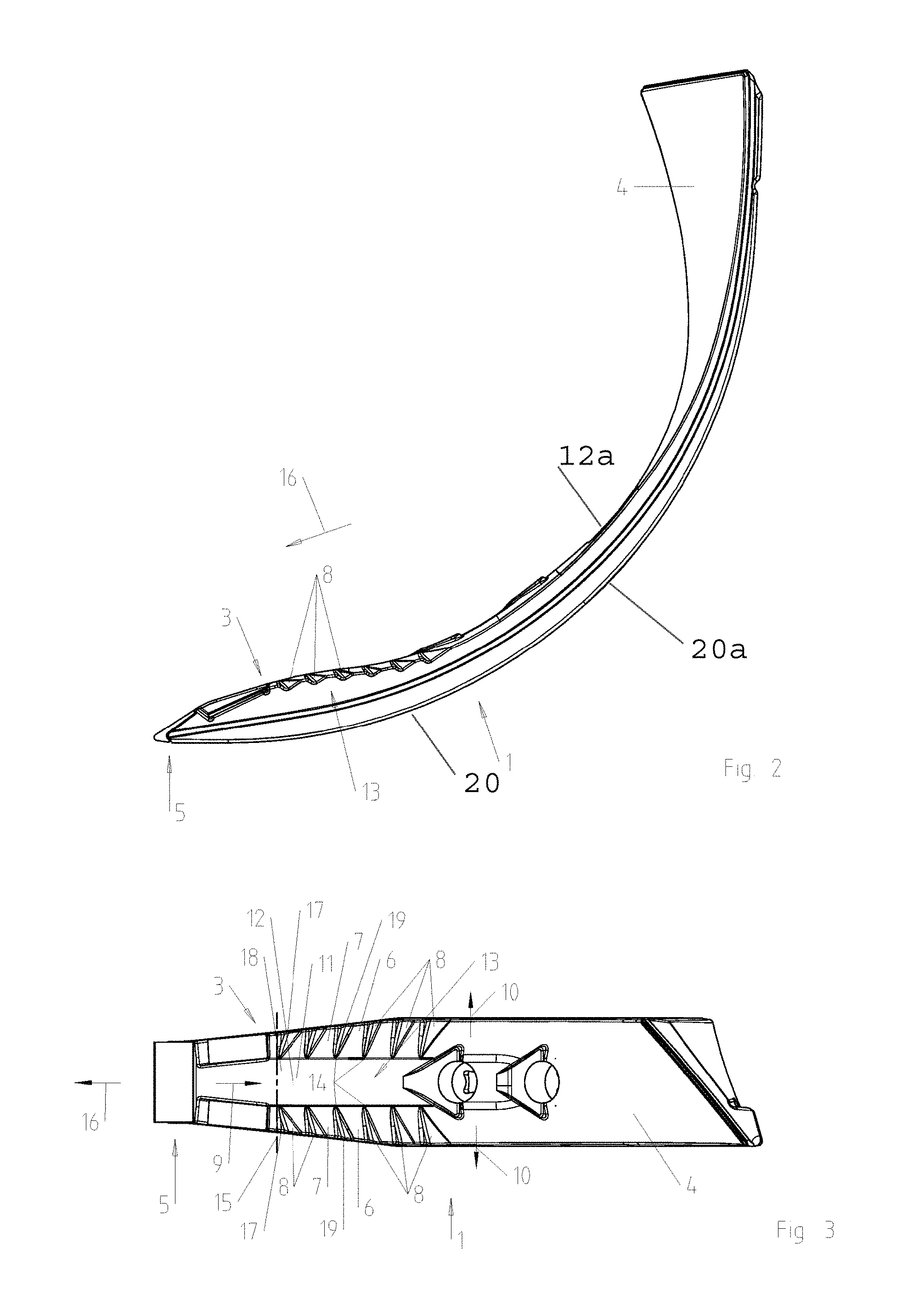
The soil-working tool for an agricultural machine, said tool being designed in the form of a cultivator blade 1, is fastened, in a manner which is not illustrated, on a tool holder, which is not illustrated either, by way of fastening means, for example screws, which can be fitted through the through-passages 2 arranged in the soil-working tool 1. The soil-working tool 1 has a front tine-like region 3, which is adjoined by a guide-plate-like element 4, which, as illustrated in the exemplary embodiment, is a self-contained unit.
Hard-metal plates 6, which may stand for example from tungsten carbide, are arranged on the tip 5 of the tine, said tip being located at the beginning of the tine-like region 3. Side strips 7, in which notch-like depressions 8 are arranged, begin on either side 6 of the cultivator blade 1, at a distance from the tip 5 of the tine. The tine-like region 3 thus has two side strips 7, which run in the longitudinal direction 9 of the cultivator blade 1 and have notch-like depressions widening outward in the transverse direction 10. Between the two side strips 7, an at least more or less smooth central-strip region 11 is located in the center of the cultivator blade 1, in the longitudinal direction 9 of the tine-like region 3 of the cultivator blade 1. More than three, in the exemplary embodiment six, notch-like depressions 8 are arranged in each side strip 7. The two side strips 7, which are provided with notch-like depressions 8, and the at least more or less smooth central strip 11 are each at least more or less of the same width.
In its tine-like region 3, the cross section of the soil-working tool 1 is curved convexly upward on its upper side 12 and lower side 20, and the at least more or less smooth central-strip region 11 is located in the upper convexly curved region 13. The notch-like depressions 8 are located in the side region 7, which slopes down laterally from the central region 11. Upper side 12 comprises a first curve 12a and lower side 20 comprises a second curve 20a, wherein the first curve and the second curve are curved in a similar direction.
The leading edge 14 of the notch-like depressions 8, as seen in each case in the direction of the tip 5 of the tine-like region 3, runs at least more or less parallel to a line 15 in the direction transverse to the direction 16 of travel of the machine and at least more or less horizontally. The trailing edge 17 of the notch-like depressions 8, as seen in the direction of the tip 5 of the tine-like region 3, runs obliquely away from the tip 5 of the tine-like region, at least at an angle of 25.degree., preferably 35.degree., in relation to the leading edge 14 of the respective notch-like depression, as it extends from the inner region 18 of the tine-like region 3 to the outer region 19 of the tine-like region 3.
The leading edges 14 of the notch-like depressions 8, which are located opposite one another in each case on the left-hand and right-hand sides, are located at least more or less on to a line 13 which runs through the leading edges 14.
* * * * *
D00000
D00001
D00002
XML
uspto.report is an independent third-party trademark research tool that is not affiliated, endorsed, or sponsored by the United States Patent and Trademark Office (USPTO) or any other governmental organization. The information provided by uspto.report is based on publicly available data at the time of writing and is intended for informational purposes only.
While we strive to provide accurate and up-to-date information, we do not guarantee the accuracy, completeness, reliability, or suitability of the information displayed on this site. The use of this site is at your own risk. Any reliance you place on such information is therefore strictly at your own risk.
All official trademark data, including owner information, should be verified by visiting the official USPTO website at www.uspto.gov. This site is not intended to replace professional legal advice and should not be used as a substitute for consulting with a legal professional who is knowledgeable about trademark law.