Side-loading quadrant deadend clamp assembly
Bundren , et al. Sept
U.S. patent number 10,411,454 [Application Number 14/721,148] was granted by the patent office on 2019-09-10 for side-loading quadrant deadend clamp assembly. This patent grant is currently assigned to Hubbell Incorporated. The grantee listed for this patent is Hubbell Incorporated. Invention is credited to Jason L. Bundren, Seydou Diop, Paul F. Zelazny.


| United States Patent | 10,411,454 |
| Bundren , et al. | September 10, 2019 |
Side-loading quadrant deadend clamp assembly
Abstract
A clamp assembly includes a body member having a cable groove formed therein to receive a cable. A keeper is connected to the body member and has a lower surface adapted to engage the cable received in the cable groove. A biasing member is disposed between the keeper and the body member.
| Inventors: | Bundren; Jason L. (Leeds, AL), Diop; Seydou (Birmingham, AL), Zelazny; Paul F. (Moody, AL) | ||||||||||
|---|---|---|---|---|---|---|---|---|---|---|---|
| Applicant: |
|
||||||||||
| Assignee: | Hubbell Incorporated (Shelton,
CT) |
||||||||||
| Family ID: | 47991674 | ||||||||||
| Appl. No.: | 14/721,148 | ||||||||||
| Filed: | May 26, 2015 |
Prior Publication Data
| Document Identifier | Publication Date | |
|---|---|---|
| US 20150255972 A1 | Sep 10, 2015 | |
Related U.S. Patent Documents
| Application Number | Filing Date | Patent Number | Issue Date | ||
|---|---|---|---|---|---|
| 13248259 | Sep 29, 2011 | 9038966 | |||
| Current U.S. Class: | 1/1 |
| Current CPC Class: | H02G 7/056 (20130101); H02G 7/02 (20130101); F16B 2/065 (20130101); Y10T 24/3958 (20150115) |
| Current International Class: | H02G 7/05 (20060101); F16B 2/06 (20060101); H02G 7/02 (20060101) |
| Field of Search: | ;248/74.4,62,63 |
References Cited [Referenced By]
U.S. Patent Documents
| 294746 | March 1884 | Straup et al. |
| 984134 | February 1911 | Gilbert |
| 1215201 | February 1917 | Sandford, Jr. |
| 1730197 | October 1929 | Elsey |
| 1809774 | June 1931 | Coates |
| 1858549 | May 1932 | Jenner |
| 1936097 | November 1933 | Noyes |
| 2026260 | December 1935 | Tarbox |
| 2059413 | November 1936 | Taylor |
| 2099465 | November 1937 | Burleson |
| 2196938 | April 1940 | Parnell |
| 2471305 | May 1949 | Card |
| 2631805 | March 1953 | Jackson |
| 2635133 | April 1953 | Badeau |
| 2640667 | June 1953 | Winn |
| 2651766 | September 1953 | Runde |
| 2669600 | February 1954 | Bergan |
| 2679032 | May 1954 | Thomas, Jr. |
| 2712167 | July 1955 | Blanchard |
| 2810116 | October 1957 | Webster |
| 2810538 | October 1957 | Anderson |
| 2942316 | June 1960 | McHorse |
| 2950936 | August 1960 | Gunthel, Jr. |
| 2968077 | January 1961 | Miller |
| 2980378 | April 1961 | Bethea |
| 2997764 | August 1961 | Lantz |
| 3141643 | July 1964 | Shrewsbury |
| 3146982 | September 1964 | Budnick |
| 3177459 | April 1965 | Toedtman |
| 3205522 | September 1965 | Then |
| 3288409 | November 1966 | Bethea, Jr. |
| 3383459 | May 1968 | Short |
| 3512565 | May 1970 | Zezza |
| 3562875 | February 1971 | Lindsey et al. |
| 3843083 | October 1974 | Angibaud |
| 3892455 | July 1975 | Sotolongo |
| 3985411 | October 1976 | Mooney |
| D243404 | February 1977 | Mooney |
| 4090762 | May 1978 | Hoffman |
| 4131257 | December 1978 | Sterling |
| 4278226 | July 1981 | Horowitz |
| 4330906 | May 1982 | Werner |
| 4383668 | May 1983 | Hall |
| 4504034 | March 1985 | Werner |
| 4707051 | November 1987 | Hall |
| 4740174 | April 1988 | Annas |
| 4817682 | April 1989 | Williams |
| 4969616 | November 1990 | Apperson |
| 4974888 | December 1990 | Childers |
| 4985003 | January 1991 | Francois |
| 5207543 | May 1993 | Kirma |
| 5243739 | September 1993 | Schmidt |
| 5435506 | July 1995 | Wiley |
| 5435507 | July 1995 | Murphy |
| 5634605 | June 1997 | Rubel |
| 5752680 | May 1998 | Mann |
| 5794897 | August 1998 | Jobin et al. |
| 5893538 | April 1999 | Onishi et al. |
| 5941483 | August 1999 | Baginski |
| 6113039 | September 2000 | Riffle |
| 6128800 | October 2000 | Vosbikian |
| 6161982 | December 2000 | Cole |
| 6220586 | April 2001 | Pavlin |
| 6327753 | December 2001 | Rushing |
| 6547481 | April 2003 | Grabenstetter |
| 6595472 | July 2003 | Pisczak |
| 6634823 | October 2003 | Sciortino |
| 6726166 | April 2004 | Goodman |
| 6877996 | April 2005 | Franks, Jr. |
| 7010822 | March 2006 | Lin |
| 7039988 | May 2006 | De France |
| 7316533 | January 2008 | Tanimura |
| 7498528 | March 2009 | De France |
| 7516582 | April 2009 | Leek |
| 7562848 | July 2009 | Tamm |
| 7666024 | February 2010 | De France |
| 7794291 | September 2010 | Goch |
| 8132767 | March 2012 | Oh |
| 9496700 | November 2016 | Bundren |
| 9520704 | December 2016 | Diop |
| 9768596 | September 2017 | Nagaki |
| 2005/0015940 | January 2005 | Stafford |
| 2012/0005863 | January 2012 | Chen |
| 2012/0210544 | August 2012 | Shibilia |
| 2013/0082152 | April 2013 | Bundren |
| 2013/0227823 | September 2013 | Diop |
| 2013/0240685 | September 2013 | Bundren |
| 2015/0232314 | August 2015 | Nagaki |
| 2015/0295393 | October 2015 | Diop |
| 2764996 | Dec 2010 | CA | |||
| 3708065 | Sep 1988 | DE | |||
| 4016050 | Nov 1991 | DE | |||
| 4015404 | Dec 1991 | DE | |||
| 102007022029 | Nov 2008 | DE | |||
| 0344862 | Dec 1989 | EP | |||
| 1795792 | Jun 2007 | EP | |||
| 2583848 | Mar 1989 | FR | |||
Other References
|
International Search Report and Written Opinion for PCT/US2012/055453 dated Dec. 10, 2012. cited by applicant. |
Primary Examiner: Ijaz; Muhammad
Attorney, Agent or Firm: Michael Best & Friedrich, LLP
Claims
What is claimed is:
1. A clamp assembly, comprising: a body member having a cable groove and a fastener opening, the fastener opening extending through the body member in a first direction along an axial length of a fastener and a second direction radially to the fastener; a keeper having a surface adapted to engage a cable received in the cable groove, and wherein the fastener extends through the fastener opening connecting the keeper to the body member, and wherein the cable can be loaded into the cable groove in a radial direction of the cable without removal of the keeper or the fastener from the body member.
2. The clamp assembly of claim 1, further comprising an internally threaded nut connected to the fastener and disposed in a chamber in the keeper.
3. The clamp assembly of claim 1, further comprising a biasing member disposed between the keeper and the body member.
4. The clamp assembly of claim 1, wherein the cable groove has a bend for supporting the cable in a first cable direction and a second cable direction.
5. The clamp assembly of claim 4, wherein the bend for supporting the cable is approximately 90 degrees.
6. The clamp assembly of claim 1, wherein a pocket is formed in the body member to receive translation of the keeper from a first position engaged with the cable to a second position disengaged with the cable.
7. The clamp assembly of claim 1, wherein the body member includes a mounting ear.
8. The clamp assembly of claim 1, wherein a width of the fastener opening expands away from a center of the fastener opening extending in the second direction.
9. The clamp assembly of claim 1, wherein the fastener opening is bound by a first angled side wall and a second angled side wall in the second direction, wherein the first angled side wall and the second angled side wall obliquely extend apart from each other.
10. The clamp assembly of claim 1, wherein the cable groove has an approximately 90 degree bend for supporting the cable in a first direction and second direction.
11. A clamp assembly, comprising: a keeper having a surface adapted to engage a cable; a body member having a cable groove, a fastener opening, a pocket for receiving the keeper, and a recessed area formed opposite the pocket; and a fastener connecting the keeper to the body member, wherein the fastener extends through the fastener opening and into the pocket, and wherein the recessed area is substantially V-shaped.
12. The clamp assembly of claim 11, wherein the pocket is a first side wall, a second side wall opposite the first side wall, and a bottom wall.
13. The clamp assembly of claim 11, wherein the pocket is a substantially U-shaped cavity.
14. The clamp assembly of claim 11, wherein the recessed area receives a head of the fastener and a nut is connected to the opposite end of the fastener, the nut received in a chamber formed in the keeper corresponding to the outer shape of the nut.
15. The clamp assembly of claim 11, wherein the recessed area expands from the fastener opening to an opposite edge of the body member.
16. The clamp assembly of claim 15, wherein the recess is bound on a first side by an angled side wall and bound on a second side by an angled side wall.
17. The clamp assembly of claim 11, further comprising a biasing member disposed between the keeper and the body member.
Description
FIELD OF THE INVENTION
The present invention relates to a clamp assembly for deadending a conductor. More particularly, the present invention relates to a clamp assembly having a biasing member disposed between a keeper and body member of the clamp assembly. Still more particularly, the present invention relates to a clamp assembly in which a conductor is secured between a keeper and body member, and a biasing member is disposed on a fastener securing the keeper to the body member.
BACKGROUND OF THE INVENTION
Deadend clamps are commonly used to secure a cable under tension, for example, an overhead electrical conductor. The deadend clamp anchors the received cable to a supporting structure, such as a tower or utility pole. The deadend clamp transmits the tension on the cable to the supporting structure.
Conventional deadend clamps typically include one or more U-bolts to clamp a keeper, which in turn applies a clamping pressure to the conductor, such as the deadend clamp disclosed in U.S. Pat. No. 5,752,680. One disadvantage associated with such deadend clamps is that the lineman must remove several nuts and washers to insert the conductor, and then the nuts and washers must be reconnected to the U-bolts. That procedure becomes even more difficult when the lineman is working with an energized conductor in the field. Accordingly, a need exists for a clamp assembly that is easily assembled.
Another disadvantage associated with conventional deadend clamps is the use of non-captive fasteners to secure the keeper to the main body. Non-captive fasteners are prone to loosening, thereby providing a less secure connection between the keeper and the main body. Accordingly, a need exists for a clamp assembly in which the keeper is securely connected to the main body to maintain clamping pressure on the conductor.
Still another disadvantage associated with conventional deadend clamps the use of external springs between the keeper and the main body. These springs can become dislodged when tightening the keeper to the main body. Additionally, these springs require the fasteners to be tightened in a specific sequence to prevent damaging the springs, thereby providing an inefficient and time consuming task for the lineman. Accordingly, a need exists for a clamp assembly having an improved biasing member between the keeper and main body.
SUMMARY OF THE INVENTION
Accordingly, it is a primary objective of the present invention to provide a clamp assembly that is easy to assemble.
A further objective of the present invention is to provide a clamp assembly in which a keeper is securely connected to a main body.
Another objective of the present invention is to provide a clamp assembly in which a biasing member is securely maintained between a keeper and a main body.
The foregoing objectives are basically attained by a clamp assembly that includes a body member having a cable groove formed therein to receive a cable. A keeper is connected to the body member and has a lower surface adapted to engage the cable received in the cable groove. A biasing member is disposed between the keeper and the body member.
The foregoing objectives are also basically attained by a clamp assembly including a body member and a keeper. A cable groove is formed in the body member to receive a cable. The keeper has a lower surface adapted to engage the cable received in the cable groove. A threaded fastener connects the keeper to the body member. An internally threaded nut disposed in a chamber in the keeper receives the fastener. A biasing member is disposed on the fastener.
Other objects, advantages and salient features of the invention will become apparent from the following detailed description, which, taken in conjunction with the annexed drawings, discloses a preferred embodiment of the invention.
As used in this application, the terms "front," "rear," "upper," "lower," "upwardly," "downwardly," and other orientational descriptors are intended to facilitate the description of the clamp assembly, and are not intended to limit the structure of the clamp assembly to any particular position or orientation.
BRIEF DESCRIPTION OF THE DRAWINGS
The above aspects and features of the present invention will be more apparent from the description for an exemplary embodiment of the present invention taken with reference to the accompanying drawings, in which:
FIG. 1 is a front perspective view of a side loading quadrant deadend clamp assembly according to an exemplary embodiment of the present invention;
FIG. 2 is a rear perspective view of the clamp assembly of FIG. 1;
FIG. 3 is a side elevational view of the clamp assembly of FIG. 1;
FIG. 4 is a top plan view of the clamp assembly of FIG. 1;
FIG. 5 is a top plan view in cross section of the clamp assembly taken along line 5-5 of FIG. 3;
FIG. 6 is a side elevational in cross section of the clamp assembly taken along line 6-6 of FIG. 4;
FIG. 7 is a front perspective view of a body member of the clamp assembly of FIG. 1;
FIG. 8 is a bottom perspective of the body member of FIG. 7;
FIG. 9 is a side elevational view of the body member of FIG. 7;
FIG. 10 is a rear elevational view of the body member of FIG. 7;
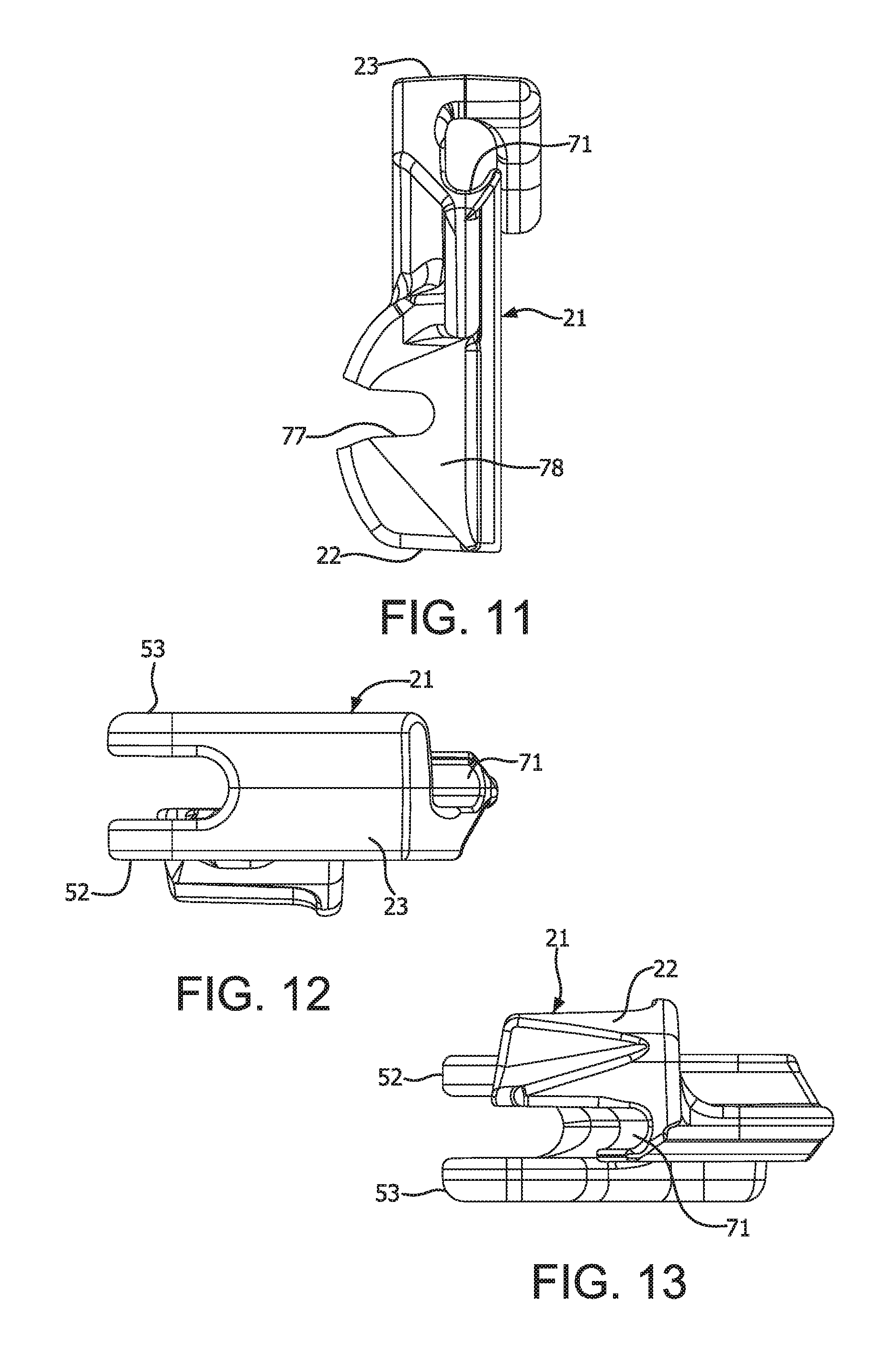
FIG. 11 is a front elevational view of the body member of FIG. 7;
FIG. 12 is a top plan view of the body member of FIG. 7;
FIG. 13 is a bottom plan view of the body member of FIG. 7;
FIG. 14 is a perspective view of a keeper of the clamp assembly of FIG. 1;
FIG. 15 is a side elevational view of the keeper of FIG. 14;
FIG. 16 is a rear elevational view of the keeper of FIG. 14;
FIG. 17 is a side elevational view of the keeper of FIG. 14;
FIG. 18 is a top plan view of the keeper of FIG. 14; and
FIG. 19 is a rear elevational view of the clamp assembly of FIG. 1.
Throughout the drawings, like reference numerals will be understood to refer to like parts, components and structures.
DETAILED DESCRIPTION OF EXEMPLARY EMBODIMENTS
As shown in FIGS. 1-19, a clamp assembly 11 includes a body member 21 and a keeper 31. The body member 21 has a cable groove 71 formed therein to receive a cable 9. The keeper 31 is connected to the body member 21 and has a lower surface 34 adapted to engage the cable 9 received in the cable groove 71. A biasing member 41 is disposed between the keeper 31 and the body member 21.
The body member 21 includes a clevis bracket 51 having first and second mounting ears 52 and 53, as shown in FIGS. 1 and 2. Openings 54 and 55 in the mounting ears 52 and 53 receive a clevis pin 56. As shown in FIG. 4, the clevis pin 56 has a first end 57 and a second end 58. A head 59 is disposed at the first end 57 of the clevis pin. An opening 60 is formed proximal the second end 58 of the clevis pin 56. The second end 58 of the clevis pin 56 is inserted through the first and second mounting ears 52 and 53. A cotter pin 61 is inserted through the opening 60 in the clevis pin 56, thereby preventing the clevis pin 56 from being removed from the mounting ears 52 and 53. The head 59 of the clevis pin 56 is larger than the openings 54 and 55 in the mounting ears 52 and 53 to limit insertion of the clevis pin through the openings 54 and 55 in the mounting ears. The cotter pin 61 has a head 62 at one end and a raised portion 63 proximal the other end to substantially prevent accidental withdrawal of the cotter pin from the clevis pin opening 60. The head 62 of the cotter pin 61 is larger than the clevis pin opening 60 to limit insertion of the cotter pin. The raised portion 62 of the cotter pin 61 flexes to allow insertion of cotter pin through the clevis pin opening 60, but prevents accidental withdrawal of the cotter pin from the clevis pin opening 60. The clevis bracket 51 allows the clamp assembly 11 to be pivotally connected to a supporting structure.
A cable groove 71 extends from a first end 22 to proximal a second end 23 of the body member 21, as shown in FIG. 2. The cable groove 71 has a 90 degree bend 72 therein, as shown in FIG. 8, to bring the conductor 9 in line with the clevis bracket 51. The cable groove 71 is preferably formed in a side of the body member 21 such that the conductor 9 can be inserted in the cable groove in a radial direction of the conductor, i.e., from the side of the clamp assembly 11. A lip 70 is formed at an outer edge of the cable groove 71, as shown in FIGS. 2 and 8, to substantially prevent the cable 9 from exiting the cable groove 71 before being clamped between the body member 21 and the keeper 31.
As shown in FIG. 6, a pocket 73 is formed in the body member 21 proximal the first end 22 thereof. The pocket 73 is preferably a substantially U-shaped cavity configured to receive the keeper 31, as shown in FIG. 3. The pocket 73 has opposite side walls 74 and 75 and a bottom wall 76 therebetween. A fastener opening 77 in the bottom wall 76 of the pocket 73 receives a fastener 13 to secure the keeper 31 to the body member 21, as shown in FIG. 6.
A recessed area 78 is formed on an outer surface 79 of the bottom wall 76 of the pocket 73, as shown in FIG. 6. The recessed area 78 is preferably substantially V-shaped, as shown in FIG. 7. The recessed area 78 receives the washer 16 disposed on the shaft 15 of the fastener, as shown in FIG. 6.
The keeper 31 is secured to a side of the body member 21 below the clevis bracket 51, as shown in FIG. 2. The keeper 31 has a fastening portion 32 and a cable engaging portion 33, as shown in FIGS. 14-18. A cable groove 34 is disposed in the cable engaging portion 33 of the keeper 31, as shown in FIGS. 5 and 16. The keeper cable groove 34 is disposed opposite the body member cable groove 71 to securely retain the cable 9 therebetween when the keeper 31 is secured to the body member 21.
The fastening portion 32 of the keeper 31 has a fastener bore 35 passing from an inner surface 36 to an outer surface 37 thereof, as shown in FIGS. 5 and 6. A chamber 38 is formed at the end of the bore proximal the outer surface 37 to receive a nut 17 disposed on the fastener 13. The chamber 38 is preferably hexagonally shaped to correspond to the outer shape of the nut 17, thereby providing a captive nut that is substantially prevented from rotational movement on the fastener 13.
An eye 65 in the body member 21 facilitates manipulation of the clamp assembly 11 by a lineman. Preferably, the eye 65 has a substantially oval shape. The cable groove preferably runs between the eye 65 and the mounting ears 52 and 53. Accordingly, the clevis pin 56 does not need to be removed to insert the conductor 9 in the cable groove 71.
The fastener 13 is inserted through a fastener opening 77 in the bottom wall 76 of the pocket 73 of the body member 21 and is received by a fastener bore 35 in the keeper 31. The fastener 13 has a head 14 and a threaded shaft 15 extending therefrom, as shown in FIGS. 5 and 6. The washer 16 and the nut 17 are disposed on the fastener shaft 13. When assembled, the washer 16 is received in the recess 78 in the body member 21 and the nut 17 is received in the chamber 38 in the fastener portion 32 of the keeper 31.
The biasing member 41 is disposed on the shaft 15 of the fastener 13, as shown in FIGS. 1-3, 5 and 6. The biasing member 41 has a first end 42 that abuts an inner surface 80 of the bottom wall 76, as shown in FIG. 3. A second end 43 of the biasing member 41 abuts the nut 17 received in the chamber 38 of the keeper 31, as shown in FIG. 6. The biasing member 41 is preferably a helical tapered spring in which a diameter at the first end 42 is larger than a diameter at the second end 43.
The body member 21 is preferably unitarily formed as a single-piece. The body member 21 is preferably made of an aluminum alloy. The keeper 31 is preferably unitarily formed as a single-piece. The keeper 31 is preferably made of an aluminum alloy.
Assembly and Operation
The deadend clamp assembly 11 is shown assembled in FIGS. 1-7. The body member 21 is connected to a support, such as a bracket, and the clevis pin 56 is passed through the mounting ear openings 54 and 55. The cotter pin 61 is then passed through the opening 60 in the clevis pin 56 to prevent the cotter pin from being removed from the mounting ears 52 and 53. The clevis pin 56 allows the clamp assembly 11 to pivot with respect to the support, thereby facilitating receiving the cable 9.
The cable 9 is inserted in the cable groove 71 from a side of the body member (i.e., in a radial direction of the cable). The lip 70, as shown in FIG. 2, prevents the cable 9 from slipping out of the cable groove 71 as the fastener 13 is tightened to draw the keeper 31 closer to the body member 21 to clamp the cable therebetween.
The washer 16 is disposed on the shaft 15 of fastener 13 such that the washer is received by the recessed area 78 in the body member 21, as shown in FIGS. 5 and 6. To clamp the cable 9 between the body member 21 and the keeper 31, a fastener 13 is inserted through the fastener opening 77 in the body member 21 and through the bore 35 in the keeper 31. The nut 17 is disposed in the chamber 38 of the fastener portion 32 of the keeper 31 and peened in the chamber 38 to substantially prevent upward (axial) movement.
The biasing member 41 is disposed on the shaft 15 of the fastener 13 such that the biasing member is prevented from being dislodged during tightening. The fastener 13 is tightened, thereby drawing the fastener portion 32 of the keeper 31 into the pocket 73 of the body member 21. The biasing member 41 is compressed as the fastener portion 32 of the keeper 31 is drawn into the pocket 73. Simultaneously, the cable portion 33 of the keeper 31 is drawn toward the retained cable 9 in the cable groove 71. Tightening of the fastener 13 is stopped when the keeper cable groove 34 engages the cable 9, thereby clamping the cable 9 between the keeper 31 and the body member 21. The chamber 38 and the peened nut 17 substantially prevent rotation and movement of the captive nut 17 on the fastener shaft 15, thereby securely retaining the keeper 31 to the body member 21. As shown in FIGS. 3 and 19, the side walls 74 and 75 substantially prevent rotation of the keeper 31 relative to the body member 21 as the keeper 31 is drawn into the pocket 73 of the body member 21.
While an advantageous embodiment has been chosen to illustrate the invention, it will be understood by those skilled in the art that various changes and modifications may be made therein without departing from the scope of the invention as defined in the appended claims.
* * * * *
D00000
D00001
D00002
D00003
D00004
D00005
D00006
D00007
D00008
D00009
XML
uspto.report is an independent third-party trademark research tool that is not affiliated, endorsed, or sponsored by the United States Patent and Trademark Office (USPTO) or any other governmental organization. The information provided by uspto.report is based on publicly available data at the time of writing and is intended for informational purposes only.
While we strive to provide accurate and up-to-date information, we do not guarantee the accuracy, completeness, reliability, or suitability of the information displayed on this site. The use of this site is at your own risk. Any reliance you place on such information is therefore strictly at your own risk.
All official trademark data, including owner information, should be verified by visiting the official USPTO website at www.uspto.gov. This site is not intended to replace professional legal advice and should not be used as a substitute for consulting with a legal professional who is knowledgeable about trademark law.