Method for displaying off-screen target indicators in motion video
Bagnall , et al. Sept
U.S. patent number 10,410,360 [Application Number 15/844,008] was granted by the patent office on 2019-09-10 for method for displaying off-screen target indicators in motion video. This patent grant is currently assigned to United States of America as Represented by Secretary of the Navy. The grantee listed for this patent is The United States of America as represented by the Secretary of the Navy, The United States of America as represented by the Secretary of the Navy. Invention is credited to Bryan D. Bagnall, Joshua Harguess, Martin T. Jaszewski, Shibin Parameswaran.


| United States Patent | 10,410,360 |
| Bagnall , et al. | September 10, 2019 |
Method for displaying off-screen target indicators in motion video
Abstract
A method for displaying off-screen target indicators in motion video comprising the steps of receiving motion video containing a series of individual video frames, selecting a target object within a selected video frame by choosing selected target object pixel space coordinates, and determining whether the selected target object pixel space coordinates are within the selected video frame. Upon determining that the selected target object pixel space coordinates are within the selected video frame, the method updates a dynamical system model with the target object geographical coordinates, longitudinal target object speed, and latitudinal target object speed. Upon determining that the selected target object pixel space coordinates are not within the selected video frame, the method calculates estimated target object geographical coordinates at time t using the dynamical system model. The method then calculates final values in the video field of view at which to draw a target indicator.
| Inventors: | Bagnall; Bryan D. (San Diego, CA), Harguess; Joshua (San Diego, CA), Parameswaran; Shibin (San Diego, CA), Jaszewski; Martin T. (San Diego, CA) | ||||||||||
|---|---|---|---|---|---|---|---|---|---|---|---|
| Applicant: |
|
||||||||||
| Assignee: | United States of America as
Represented by Secretary of the Navy (Washington, DC) |
||||||||||
| Family ID: | 66813927 | ||||||||||
| Appl. No.: | 15/844,008 | ||||||||||
| Filed: | December 15, 2017 |
Prior Publication Data
| Document Identifier | Publication Date | |
|---|---|---|
| US 20190188868 A1 | Jun 20, 2019 | |
| Current U.S. Class: | 1/1 |
| Current CPC Class: | G06T 7/251 (20170101); G06T 7/277 (20170101); G06T 7/75 (20170101); G06T 2207/10016 (20130101); G06T 2207/30241 (20130101); G06T 2207/20104 (20130101); G06T 2207/20092 (20130101) |
| Current International Class: | G06T 7/246 (20170101); G06T 7/277 (20170101); G06T 7/73 (20170101) |
References Cited [Referenced By]
U.S. Patent Documents
| 4286289 | August 1981 | Ottesen et al. |
| 6674877 | January 2004 | Jojic |
| 8512115 | August 2013 | Namba et al. |
| 8958602 | February 2015 | Lane et al. |
| 2007/0031003 | February 2007 | Cremers |
| 2011/0129119 | June 2011 | Eggert |
| 2012/0322523 | December 2012 | Woodard et al. |
| 2014/0375493 | December 2014 | Weisenburger |
| 2017/0178355 | June 2017 | Alibay |
| 2018/0239966 | August 2018 | Xiao |
| WO2008052254 | May 2008 | WO | |||
Other References
|
Baudisch et al., "Halo: a Technique for Visualizing Off-Screen Locations," Proc. Conference on Human factors in Computing Systems (CHI), vol. No. 5, Issue No. 1, pp: 481-488. (Year: 2003). cited by examiner . Gustafson et al., "Comparing visualizations for tracking off-screen moving targets," Proc. Conference on Human factors in Computing Systems (CHI) , 2007 ACM Press pp: 2399-2404. (Year: 2007). cited by examiner . Gao et al., "A Kalman Filtering Perspective for Multiatlas Segmentation," SIAM J Imaging Sci. 2015 ; 8(2): 1007-1029. doi:10.1137/130933423. (Year: 2015). cited by examiner. |
Primary Examiner: Shin; Soo
Attorney, Agent or Firm: Naval Information Warfare Center Pacific Eppele; Kyle
Government Interests
FEDERALLY SPONSORED RESEARCH AND DEVELOPMENT
The Method for Displaying Off-Screen Target Indicators in Motion Video is assigned to the United States Government and is available for licensing and commercial purposes. Licensing and technical inquiries may be directed to the Office of Research and Technical Applications, Space and Naval Systems Center Pacific (Code 72120), San Diego, Calif., 92152 via telephone at (619) 553-2778 or email at ssc_pac_t2@navy.mil. Reference Navy Case 103403.
Claims
We claim:
1. A method for displaying target indicators in motion video comprising: receiving a motion video containing a plurality of video frames; initializing a dynamical system model; selecting a target object within a selected video frame by choosing selected target object pixel space coordinates; determining whether the selected target object pixel space coordinates are within the selected video frame; upon determining the selected target object pixel space coordinates are within the selected video frame, updating the dynamical system model with a target object geographical coordinates, longitudinal target object speed, and latitudinal target object speed; upon determining the selected target object pixel space coordinates are not within the selected video frame, calculating an estimated target object geographical coordinates at time t using the dynamical system model; calculating a final value for the dynamical system model; and drawing the target indicators at the final value for the dynamical system model.
2. The method of claim 1, wherein the step of upon determining the selected target object pixel space coordinates are within the selected video frame further comprises sub steps of tracking the selected target object pixel space coordinates; bilinearly transforming the selected target object pixel space coordinates into selected target object geographical coordinates; and calculating the longitudinal target object speed and the latitudinal target object speed using the selected target object geographical coordinates.
3. The method of claim 1, wherein the longitudinal target object speed is calculated as a circle distance in a longitudinal direction between selected target object geographical coordinates in the selected video frame and the selected target object geographical coordinates in a previous video frame.
4. The method of claim 1, wherein the upon determining the selected target object pixel space coordinates are not within the selected video frame step further comprises substeps of stopping the updating of the dynamical system model; calculating an estimated target object geographical coordinates at the time t using the dynamical system model; and transforming the estimated target object geographical coordinates into estimated target object pixel space coordinates.
5. The method of claim 4, further comprising a step of calculating a field of view midpoint.
6. The method of claim 4, further comprising steps of determining whether the estimated target pixel space coordinates are behind a frame of view; upon determining the target object pixel space coordinates are behind the frame of view, updating the target object pixel space coordinates by multiplying the target object pixel space coordinates by negative one; and upon determining the target object pixel space coordinates are not behind the frame of view, leaving the target object pixel space coordinates unchanged.
7. The method of claim 4, further comprising steps of calculating adjusted values by subtracting a field of view midpoint from the estimated target object pixel space coordinates; calculating a first slope between the estimated target object pixel space coordinates and the field of view midpoint; calculating screen bounds values by multiplying the field of view midpoint by 0.9; updating the adjusted values using the screen bounds values and the first slope; and calculating the final value for the dynamical system model by adding the field of view midpoint to the adjusted values.
8. The method of claim 4, further comprising a step of calculating a first distance between a field of view midpoint and the estimated target object geographic coordinates.
9. The method of claim 5, wherein the field of view midpoint is calculated by multiplying a frame of view dimension by one-half.
10. The method of claim 8, wherein the first distance is calculated by transforming the field of view midpoint into screen center geographic coordinates, and calculating a second distance between the screen center geographic coordinates and the estimated target object geographic coordinates.
11. The method of claim 8, wherein the target indicator displays the first distance.
12. The method of claim 2, wherein the dynamical system model is a Kalman filter, and wherein the target object is tracked by a key point tracking method.
13. A method for displaying target indicators in motion video comprising: receiving a motion video containing a plurality of video frames; selecting a target object within a selected video frame by choosing selected target object pixel space coordinates; initializing a dynamical system model; determining whether the selected target object pixel space coordinates are within the selected video frame; upon determining the selected target object pixel space coordinates are within the selected video frame, tracking the selected target object pixel space coordinates; bilinearly transforming the selected target object pixel space coordinates into selected target object geographical coordinates; calculating a longitudinal target object speed and a latitudinal target object speed using the selected target object geographical coordinates; updating the dynamical system model with the selected target object geographical coordinates, the longitudinal target object speed, and the latitudinal target object speed; upon determining the selected target object pixel space coordinates are not within the selected video frame, stopping the updating of the dynamical system model; calculating an estimated target object geographical coordinates at time t using the dynamical system model; transforming the estimated target object geographical coordinates into estimated target object pixel space coordinates; calculating a field of view midpoint; determining whether the estimated target object pixel space coordinates are behind a frame of view; upon determining the target object pixel space coordinates are behind the frame of view, updating the target object pixel space coordinates by multiplying the target object pixel space coordinates by negative one; upon determining the target object pixel space coordinates are not behind the frame of view, leaving the target object pixel space coordinates unchanged; calculating adjusted values by subtracting the field of view midpoint from the estimated target object pixel space coordinates; calculating a first slope between the estimated target object pixel space coordinates and the field of view midpoint; calculating screen bounds values by multiplying the field of view midpoint by 0.9; updating the adjusted values using the screen bounds value and the first slope; calculating a final value for the dynamical system model by adding the field of view midpoint to the adjusted values; calculating a first distance between the field of view midpoint and the estimated target object geographic coordinates; and drawing the target indicators at the final value for the dynamical system model.
14. The method of claim 13, wherein the longitudinal target object speed is calculated as a circle distance in a longitudinal direction between the selected target object geographical coordinates in the selected video frame and selected target object geographical coordinates in a previous video frame.
15. The method of claim 13, wherein the field of view midpoint is calculated by multiplying a frame of view dimension by one-half.
16. The method of claim 13, wherein the first distance is calculated by transforming the field of view midpoint into screen center geographic coordinates, and calculating a second distance between the screen center geographic coordinates and the estimated target object geographical coordinates.
17. The method of claim 13, wherein the target indicator displays the first distance.
18. The method of claim 13, wherein the dynamical system model is a Kalman filter.
19. The method of claim 13, wherein the target object is tracked by a key point tracking method.
20. A method for displaying target indicators in motion video comprising: receiving a motion video containing a plurality of video frames; selecting a target object within a selected video frame by choosing selected target object pixel space coordinates; initializing a dynamical system model; determining whether the selected target object pixel space coordinates are within the selected video frame; upon determining the selected target object pixel space coordinates are within the selected video frame, tracking the selected target object pixel space coordinates; bilinearly transforming the selected target object pixel space coordinates into selected target object geographical coordinates; calculating a longitudinal target object speed and a latitudinal target object speed using the selected target object geographical coordinates; updating the dynamical system model with the selected target object geographical coordinates, longitudinal target object speed, and latitudinal target object speed; wherein the longitudinal target object speed is calculated as a great circle distance in a longitudinal direction between the selected target object geographical coordinates in the selected video frame and the selected target object geographical coordinates in a previous video frame; upon determining the selected target object pixel space coordinates are not within the selected video frame, stopping the updating of the dynamical system model; calculating an estimated target object geographical coordinates at time t using the dynamical system model; transforming the estimated target object geographical coordinates into estimated target object pixel space coordinates; calculating a field of view midpoint; determining whether the estimated target object pixel space coordinates are behind a frame of view; upon determining the target object pixel space coordinates are behind the frame of view, updating the target object pixel space coordinates by multiplying the target object pixel space coordinates by negative one; upon determining the target object pixel space coordinates are not behind the frame of view, leaving the target object pixel space coordinates unchanged; calculating adjusted values by subtracting the field of view midpoint from the estimated target object pixel space coordinates; calculating a first slope between the estimated target object pixel space coordinates and the field of view midpoint; calculating screen bounds values by multiplying the field of view midpoint by 0.9; updating the adjusted values using the screen bounds value and the first slope; calculating final value by adding the field of view midpoint to the adjusted values; calculating a first distance between the field of view midpoint and the estimated target object geographic coordinates; drawing a target indicator at the final value; wherein the field of view midpoint is calculated by multiplying a frame of view dimension by one-half; wherein the first distance is calculated by transforming the field of view midpoint into screen center geographic coordinates, and calculating the distance between the screen center geographic coordinates and the estimated target object geographical coordinates; wherein the target indicator displays the first distance; wherein the dynamical system model is a Kalman filter, and wherein the target object is tracked by a key point tracking method.
Description
BACKGROUND OF THE INVENTION
This invention provides a method that can automatically display indicators in real time showing the direction and distance to an off-screen target. It is designed as a way for an operator of any platform equipped with a motion video sensor to be able to maintain situational awareness. The operator may allow the method to detect targets automatically, or may select targets manually. The method then computes the location of the target relative to the video field of view and displays the information on screen. This allows the camera operator to easily reorient the camera toward the off-screen targets with minimal cognitive burden. The same information used to display the target locations could also be translated into a signal for motors which could automatically orient the camera to the off-screen target.
It can be especially difficult to maintain orientation with respect to a target object while operating a camera attached to a moving platform. This invention addresses lowering the cognitive burden required to point the camera at previously spotted target objects or previously known geographic coordinates. When scanning a scene with a camera, it can be difficult to determine which way the camera needs to be panned to go back towards the object once the target object leaves the camera's field of view.
Current methods employed in the field include displaying the camera platform heading on the video screen. While this can help keep the operator oriented, this method requires the operator to remember the bearings to the target objects the operator is monitoring and estimate for himself the motion of the object while outside the field of view. By contrast, the present invention addresses these shortcomings by tracking target object locations, updating them based on a predictive dynamical model, and automatically displays a target indicator showing where the camera needs to turn in order to point towards the target object.
In a different field, video games have used a similar indicator to display the location of objects within the video game environment but outside of the user's field of view that the user is trying to find. In contrast to the present invention however, the video game programmer is able to directly compute the locations of the targets relative to the field of view because all of the object locations in a video game environment are precisely known to the programmer. Unlike the method used by video games, this invention does not need to know the precise location of the target objects and uses instead a dynamical model to predict the target object location relative to the video camera field of view.
SUMMARY OF THE INVENTION
The present invention is for a method for displaying off-screen target indicators in motion video comprising the steps of receiving motion video containing a series of individual video frames, selecting a target object within a selected video frame by choosing selected target object pixel space coordinates, and determining whether the selected target object pixel space coordinates are within the selected video frame. Upon determining that the selected target object pixel space coordinates are within the selected video frame, the method updates a dynamical system model with the target object geographical coordinates, longitudinal target object speed, and latitudinal target object speed. Upon determining that the selected target object pixel space coordinates are not within the selected video frame, the method calculates estimated target object geographical coordinates at time t using the dynamical system model. The method then calculates final values in the video field of view at which to draw a target indicator.
BRIEF DESCRIPTION OF THE DRAWINGS
Throughout the several views, like elements are referenced using like elements. The elements in the figures are not drawn to scale, and some dimensions may be exaggerated for clarity.
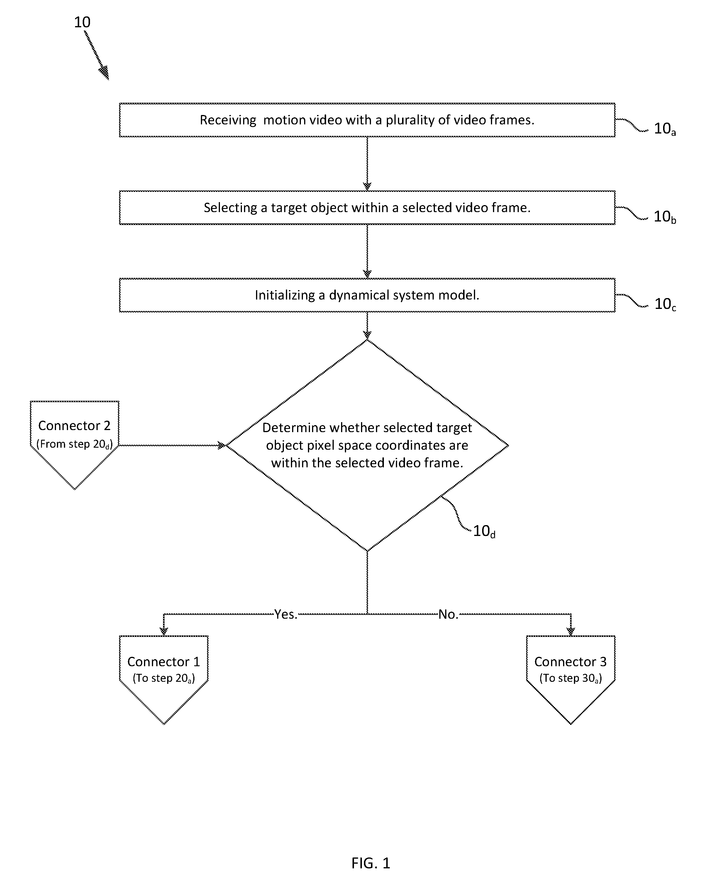
FIG. 1 is a flowchart of a method for displaying off-screen target indicators in motion video, in accordance with one embodiment of the present disclosure.
FIG. 2 is a flowchart of a method for displaying off-screen target indicators in motion video, in accordance with one embodiment of the present invention, and is a continuation of FIG. 1.
FIG. 3 is a flowchart of a method for displaying off-screen target indicators in motion video, in accordance with one embodiment of the present invention, and is a continuation of FIG. 1.
FIG. 4 is a flowchart of a method for displaying off-screen target indicators in motion video, in accordance with one embodiment of the present invention, and depicts the steps of FIGS. 1 and 3 in greater detail.
FIG. 5 depicts a display screen showing targets in a field of view in accordance with one embodiment of the present invention.
FIG. 6 depicts a display screen showing the targets of FIG. 5 after they have departed the field of view in accordance with one embodiment of the present invention.
DETAILED DESCRIPTION OF THE INVENTION
While the invention may be embodied in different forms, the drawings and this section describe in detail specific embodiments of the invention with the understanding that the present disclosure is to be considered merely a preferred embodiment of the invention, and is not intended to limit the invention in any way.
This invention may be practiced using motion video cameras, and provides a method that can automatically generate and draw target indicators which indicate the direction and distance to an off-screen target. The motion video contains metadata including the position the video was taken at each video frame. This metadata enables the longitude and latitude coordinates of the target object to be calculated.
Using the present method, the operator initially receives motion video containing a plurality of video frames and positional metadata, step 10.sub.a, depicted in FIG. 1. The operator has the choice of allowing the method to automatically detect targets, or manually selecting targets that the operator would like to track. In either case, the operator or method selects a target object within a selected video frame, step 10.sub.b. The method initializes a four-state dynamical system model such as a Kalman filter (other non-linear trackers such as particle filters may be used in the alternate), which tracks at least the target object geographical coordinates (in longitude and latitude) and the target object velocity (in longitudinal target object speed and latitudinal target object speed), step 10.sub.c. The dynamical system model is initialized in step 10.sub.c with the location of the tracked target, converted from pixel coordinates to geographical coordinates using a bilinear transform based on information contained in the metadata of the video.
The method then determines whether the target object is within the field of view by testing whether the selected target object pixel space coordinates are within the selected video frame, step 10.sub.d. The method performs step 10.sub.d by checking the pixel space coordinates of the tracked target (x,y,z) (where x is the column coordinate, y is the row coordinate, and z is 1 if the target is in front of the field of view, and -1 if the target is behind the field of view) against the width and height of the selected video frame (x.sub.limy.sub.lim). The method first checks if the conditions defined by equations 1-3 (below) are true: z.gtoreq.0; (1) 0<x<x.sub.lim; and (2) 0<y<y.sub.lim. (3) In step 10.sub.d, if the conditions define by equations 1-3 are all true, then the tracked target is still within the video frame, and the method proceeds to step 20.sub.a, depicted in FIG. 2. In step 20.sub.a, while the target object is within the field of view, the target object is tracked from frame to frame. The target object can be tracked in step 20.sub.a by tracking the target object's key points (e.g., using the Scale Invariant Feature Transform or Speeded Up Robust Features tracking), template matching, correlation filters, Tracking-Learning-Detection, or other methods. Within step 20.sub.a, the updated selected target object pixel space coordinates are extracted from the tracker for each new frame.
Next, a bilinear transform is used to convert the selected object pixel space coordinates from the pixel space to selected object geographical coordinates in longitude and latitude, step 20.sub.b. For each new frame where the target object is within the field of view, the tracker of step 20.sub.a reports the target object pixel space coordinates in row and column number. Using geo-location information from the video metadata, each pixel in the video frame may be mapped to a real-world longitude and latitude using the bilinear transform, step 20.sub.b. The target object pixel space coordinates can then be correlated with a real world longitude and latitude. Additionally, the bilinear transform of step 20.sub.b may be substituted with an alternative means for conversion from pixel coordinates to geographic coordinates such as a bicubic transform.
The longitudinal target object speed and latitudinal target object speed can now be calculated in step 20.sub.c. Where the target object geographical coordinates are known for each frame and the framerate of the video is known, the method can calculate the speed of the target object. For example, a ship may appear at 33.213.degree. N, 117.321.degree. W at a time t.sub.0. In a later frame corresponding to time t.sub.1, the ship may appear at 33.345.degree. N, 117.789.degree. W. The method can calculate or estimate the distance between the two points using known methods such as the Haversine formula (in this case, approximately 29 miles). If the time between the first video frame at t.sub.0 and second video frame at t.sub.1 is one hour, then we know the speed of the target is approximately 29 miles per hour. After the longitudinal target object speed and latitudinal target object speed is calculated in step 20.sub.c, the dynamical model can be updated with the selected target object geographic coordinates, longitudinal target object speed, and latitudinal target object speed, step 20.sub.d. The method then returns to step 10.sub.d.
Once the target object is no longer within the video frame, the target object cannot be directly tracked, and the dynamical model no longer updated. At step 10.sub.d, if any of equations 1, 2, or 3 are false, then the target object is no longer within the field of view, and the method proceeds to step 30.sub.a, depicted in FIG. 3. First, the dynamical system model updates are stopped, step 30.sub.a. Next, the current location of the target object at time t is estimated using the dynamical system model, step 30.sub.b. Because the dynamical system model (a Kalman filter in this embodiment) produces the same output dimensions as are input, the results of step 30.sub.b are estimated target object geographical coordinates output in longitude and latitude. These estimated target object geographical coordinates must be transformed into estimated target object pixel space coordinates, step 30.sub.c. The estimated target object pixel space coordinates in row and column at time t is depicted as (x,y,z) (where x is the column coordinate, y is the row coordinate, and z is 1 if the target is in front of the field of view, and -1 if the target is behind the field of view). The field of view midpoint (x.sub.0,y.sub.0,z) is next calculated in step 30.sub.d according to equation 4:
##EQU00001## After calculating the field of view midpoint in step 30.sub.d, the method determines whether the estimated target object pixel space coordinates (x,y,z) are behind the frame of view. If z<0, then the target object is behind the frame of view, and the estimated target object pixel space row and column values must be multiplied by -1 and saved as adjusted values (x.sub.adj,y.sub.adj,z), according to equation 5 below, step 30.sub.f: (x.sub.adj,y.sub.adj,z).rarw.(-x,-y,z). (5) If the estimated target object pixel space coordinates (x,y,z) are not behind the frame of view (if z.gtoreq.0), then the adjusted values (x.sub.adj,y.sub.adj,z) are simply set as the unchanged estimated target pixel space coordinates (x,y,z), step 30.sub.g, equation 6 below. (x.sub.adj,y.sub.adj,z).rarw.(x,y,z). (6)
Next, adjusted values (x.sub.adj,y.sub.adj,z) are calculated according to step 30.sub.h, equation 7: (x.sub.adj,y.sub.adj,z)=(x-x.sub.0,y-y.sub.0,z). (7) The slope of the line connecting the field of view midpoint and the target object (hereinafter "first slope") can be calculated in step 30.sub.i according to equation 8:
##EQU00002## Screen bounds values (x.sub.s,y.sub.s,z) are then calculated in step 30.sub.j according to equation 9: (x.sub.s,y.sub.s,z)=(0.9x.sub.0,0.9y.sub.0,z). (9) The adjusted values (x.sub.adj,y.sub.adj,z) are then updated in step 30.sub.k.
In step 30.sub.k, the method first checks if y.sub.adj>0. If y.sub.adj>0, then the method updates the adjusted values according to equation 10:
##EQU00003## If y.sub.adj.ltoreq.0 however, then the adjusted values are instead updated according to equation 11:
##EQU00004## After having updated the adjusted values according to equation 10 or equation 11, the method checks whether x.sub.adj>x.sub.s. If this condition is true, then the adjusted values are further updated according to equation 12: (x.sub.adj,y.sub.adj,z)=(x.sub.s,mx.sub.s,z). (12) If the condition x.sub.adj>x.sub.s is not true, then the method checks if the condition x.sub.adj<-x.sub.s is true. If x.sub.adj<-x.sub.s, then the adjusted values are further updated according to equation 13: (x.sub.adj,y.sub.adj,z)=(-x.sub.s,-mx.sub.s,z). (13)
After having updated the adjusted values (x.sub.adj,y.sub.adj,z), the method now calculates final values (x.sub.final,y.sub.final,z) according to equation 14, step 30.sub.l: (x.sub.final,y.sub.final,z)=(x.sub.adj+x.sub.0,y.sub.adj+y.sub.0,z). (14) Additionally, the distance (hereinafter "first distance") between the field of view midpoint and the tracked target can be calculated using the known longitude and latitude of the screen center from the video metadata, estimated target object geographical coordinates, and the Haversine formula, step 30.sub.m. A target indicator is finally drawn at the final values (x.sub.final,y.sub.final,z) on the video frame, step 30.sub.n. This target indicator can be annotated with the distance to the target object, calculated in step 30.sub.m. The above steps are shown in flow chart format in FIGS. 1, 2, 3, and 4.
FIG. 5 is a display screen 205 showing targets 210, 220 in the field of view, in accordance with one embodiment of the present disclosure. The first target 210 can be seen on the right side of the display screen 205. The second target 220 can be seen on the left side of the display screen 205. The user can manually select targets 210, 220 by drawing a first box 230 around target 210 and a second box 240 around target 240. Alternatively, the method may have automatically detected targets 210, 200 and assigned coordinates to the targets 210, 200 by generating and displaying boxes 230, 240 around the targets 210, 220. A center indication 250 may appear at on display screen 205 to indicate the very center of the image. As targets 210, 220 move, they may exit the field of view of display screen 205.
FIG. 6 shows the targets of FIG. 5 as they have veered off-screen in accordance with one embodiment of the present disclosure. The wider field of view shows the physical locations of targets 210, 220 after they have moved out of the frame of view of the display screen 205. In the embodiment shown in FIG. 6, the indicators 310, 320 are shown in the form of arrows in order to represent the direction of off-screen targets 210, 220. These indicators 310, 320 could further depict the distance from each of targets 210, 220 to the center of the display screen 205.
From the above description of the present invention, it is manifest that various techniques may be used for implementing its concepts without departing from the scope of the claims. The described embodiments are to be considered in all respects as illustrative and not restrictive. The method disclosed herein may be practiced in the absence of any element that is not specifically claimed and/or disclosed herein. It should also be understood that the present invention is not limited to the particular embodiments described herein, but is capable of being practiced in many embodiments without departure from the scope of the claims.
* * * * *
D00000
D00001
D00002
D00003
D00004
D00005
D00006
M00001
M00002
M00003
M00004
XML
uspto.report is an independent third-party trademark research tool that is not affiliated, endorsed, or sponsored by the United States Patent and Trademark Office (USPTO) or any other governmental organization. The information provided by uspto.report is based on publicly available data at the time of writing and is intended for informational purposes only.
While we strive to provide accurate and up-to-date information, we do not guarantee the accuracy, completeness, reliability, or suitability of the information displayed on this site. The use of this site is at your own risk. Any reliance you place on such information is therefore strictly at your own risk.
All official trademark data, including owner information, should be verified by visiting the official USPTO website at www.uspto.gov. This site is not intended to replace professional legal advice and should not be used as a substitute for consulting with a legal professional who is knowledgeable about trademark law.