Wireless sensor device with wireless remote programming
Reeder , et al. Sept
U.S. patent number 10,409,239 [Application Number 15/449,480] was granted by the patent office on 2019-09-10 for wireless sensor device with wireless remote programming. This patent grant is currently assigned to Honeywell International Inc.. The grantee listed for this patent is Honeywell International Inc.. Invention is credited to Patrick Brisbine, Jeffrey M. Reeder, Robert Thomas.

| United States Patent | 10,409,239 |
| Reeder , et al. | September 10, 2019 |
Wireless sensor device with wireless remote programming
Abstract
The disclosure relates generally to wireless sensor devices, and more particularly, to remote programming of wireless sensor devices. A wireless sensor device wirelessly may receive messages from a remotely located device to a wireless sensor device. The wireless sensor device may be programmed via the receive messages. In one example, a building controller may be programmed to wirelessly send one or more messages to a wireless sensor device in order to change the behavior of the wireless sensor device, even while the wireless sensor device and building controller are on-line and actively controlling a building control system. In some instances, a technician or installer may use a diagnostic or setup tool to send one or more messages to a wireless sensor device to change the behavior of the wireless sensor device. These are just some examples.
| Inventors: | Reeder; Jeffrey M. (Redmond, WA), Thomas; Robert (Brier, WA), Brisbine; Patrick (Sammamish, WA) | ||||||||||
|---|---|---|---|---|---|---|---|---|---|---|---|
| Applicant: |
|
||||||||||
| Assignee: | Honeywell International Inc.
(Morris Plains, NJ) |
||||||||||
| Family ID: | 49995621 | ||||||||||
| Appl. No.: | 15/449,480 | ||||||||||
| Filed: | March 3, 2017 |
Prior Publication Data
| Document Identifier | Publication Date | |
|---|---|---|
| US 20170176035 A1 | Jun 22, 2017 | |
Related U.S. Patent Documents
| Application Number | Filing Date | Patent Number | Issue Date | ||
|---|---|---|---|---|---|
| 13556971 | Jul 24, 2012 | 9621371 | |||
| Current U.S. Class: | 1/1 |
| Current CPC Class: | F24F 11/62 (20180101); H04L 12/2816 (20130101); G05B 15/02 (20130101); F24F 11/30 (20180101); F24F 11/65 (20180101); F24F 2120/10 (20180101); F24F 2140/60 (20180101); F24F 11/46 (20180101); H04L 2012/2841 (20130101); F24F 2120/12 (20180101) |
| Current International Class: | G05B 15/02 (20060101); F24F 11/62 (20180101); F24F 11/65 (20180101); F24F 11/46 (20180101); H04L 12/28 (20060101); F24F 11/30 (20180101) |
| Field of Search: | ;700/276 |
References Cited [Referenced By]
U.S. Patent Documents
| 3643183 | February 1972 | Geffe |
| 3715693 | February 1973 | Fletcher et al. |
| 3758885 | September 1973 | Voorman et al. |
| 4264873 | April 1981 | Kominami et al. |
| 4529947 | July 1985 | Biard et al. |
| 4549169 | October 1985 | Moura et al. |
| 4550312 | October 1985 | Galloway et al. |
| 4614945 | September 1986 | Brunius et al. |
| 4812785 | March 1989 | Pauker |
| 4843638 | June 1989 | Walters |
| 4918425 | April 1990 | Greenberg et al. |
| 4933668 | June 1990 | Oyer et al. |
| 4968966 | November 1990 | Jasinski et al. |
| 5003619 | March 1991 | Morris et al. |
| 5063371 | November 1991 | Oyer et al. |
| 5097671 | March 1992 | Jeong-Hun |
| 5287109 | February 1994 | Hesse |
| 5322034 | June 1994 | Willham et al. |
| 5382948 | January 1995 | Richmond |
| 5390206 | February 1995 | Rein et al. |
| 5392003 | February 1995 | Nag et al. |
| 5395042 | March 1995 | Riley et al. |
| 5428388 | June 1995 | von Bauer et al. |
| 5428602 | June 1995 | Kemppainen |
| 5428637 | June 1995 | Oliva, Jr. et al. |
| 5430409 | July 1995 | Buck et al. |
| 5438329 | August 1995 | Gastouniotis et al. |
| 5451898 | September 1995 | Johnson et al. |
| 5465399 | November 1995 | Oberholtzer et al. |
| 5481259 | January 1996 | Bane |
| 5544036 | August 1996 | Brown, Jr. et al. |
| 5594447 | January 1997 | Usui et al. |
| 5595342 | January 1997 | McNair et al. |
| 5613228 | March 1997 | Tuttle et al. |
| 5642071 | June 1997 | Sevenhans et al. |
| 5659303 | August 1997 | Adair, Jr. |
| 5663774 | September 1997 | Baik |
| 5726603 | March 1998 | Chawla et al. |
| 5745049 | April 1998 | Akiyama et al. |
| 5745849 | April 1998 | Britton |
| 5767664 | June 1998 | Price |
| 5767791 | June 1998 | Stoop et al. |
| 5782036 | July 1998 | Bertieri et al. |
| 5809013 | September 1998 | Kackman |
| 5822544 | October 1998 | Chaco et al. |
| 5825327 | October 1998 | Krasner |
| 5847623 | December 1998 | Hadjichristos |
| 5867763 | February 1999 | Dean et al. |
| 5905442 | May 1999 | Mosebrook et al. |
| 5963650 | October 1999 | Simionescu et al. |
| 5973613 | October 1999 | Reis et al. |
| 6034603 | March 2000 | Steeves |
| 6052600 | April 2000 | Fette et al. |
| 6058137 | May 2000 | Partyka |
| 6075513 | June 2000 | Reddy et al. |
| 6084530 | July 2000 | Pidwerbetsky et al. |
| 6087930 | July 2000 | Kulka et al. |
| 6091715 | July 2000 | Vucetic et al. |
| 6175860 | January 2001 | Gaucher |
| 6198394 | March 2001 | Jacobsen et al. |
| 6259399 | July 2001 | Krasner |
| 6275166 | August 2001 | del Castillo et al. |
| 6353846 | March 2002 | Fleeson |
| 6366572 | April 2002 | Esterberg et al. |
| 6366622 | April 2002 | Brown et al. |
| 6414963 | July 2002 | Gemar |
| 6624750 | September 2003 | Marman et al. |
| 6631271 | October 2003 | Logan |
| 6727816 | April 2004 | Helgeson |
| 6768901 | July 2004 | Osborn et al. |
| 6785255 | August 2004 | Sastri et al. |
| 6788271 | September 2004 | Koo et al. |
| 6823181 | November 2004 | Kohno et al. |
| 6836506 | December 2004 | Anderson |
| 6901066 | May 2005 | Helgeson |
| 6931078 | August 2005 | McCorkle et al. |
| 6987793 | January 2006 | Dhar et al. |
| 6996402 | February 2006 | Logan et al. |
| 7002910 | February 2006 | Garcia-Luna-Aceves et al. |
| 7015789 | March 2006 | Helgeson |
| 7184524 | February 2007 | Digate et al. |
| 7298716 | November 2007 | Abraham et al. |
| 7394782 | July 2008 | Davis |
| 7412265 | August 2008 | Chen et al. |
| 7446647 | November 2008 | Helgeson |
| 7450926 | November 2008 | Chang et al. |
| 7471942 | December 2008 | Subramanian et al. |
| 7620409 | November 2009 | Budampati et al. |
| 7636042 | December 2009 | Hameed |
| 7684408 | March 2010 | Wakabayashi |
| 7689843 | March 2010 | Hassan et al. |
| 8139623 | March 2012 | Nielsen et al. |
| 8710983 | April 2014 | Malkowski |
| 9621371 | April 2017 | Reeder et al. |
| 2002/0011923 | January 2002 | Cunningham et al. |
| 2002/0146985 | October 2002 | Naden |
| 2003/0086393 | May 2003 | Vasudevan et al. |
| 2003/0198280 | October 2003 | Wang et al. |
| 2006/0056322 | March 2006 | Simpson et al. |
| 2007/0037610 | February 2007 | Logan |
| 2007/0207841 | September 2007 | Amerga et al. |
| 2010/0106319 | April 2010 | Grohman et al. |
| 2010/0287559 | November 2010 | Mergen et al. |
| 2010/0291977 | November 2010 | Vuong |
| 2011/0066297 | March 2011 | Saberi et al. |
| 2011/0137614 | June 2011 | Wheeler et al. |
| 2011/0264280 | October 2011 | Grabinger et al. |
| 2012/0033584 | February 2012 | Corroy |
| 2012/0095622 | April 2012 | Lynch |
| 673184 | Feb 1990 | CH | |||
| 352917 | May 1922 | DE | |||
| 4344172 | Jun 1995 | DE | |||
| 19548650 | Jun 1997 | DE | |||
| 0565507 | Oct 1993 | EP | |||
| 0574230 | Dec 1993 | EP | |||
| 0607562 | Jul 1994 | EP | |||
| 0893931 | Jan 1999 | EP | |||
| 2592977 | Jul 1987 | FR | |||
| 2273593 | Jun 1994 | GB | |||
| 9307702 | Apr 1993 | WO | |||
| 9818225 | Apr 1998 | WO | |||
| 0070572 | Nov 2000 | WO | |||
Other References
|
"Image Rejection in Mixers," copyright AAA, 1996. cited by applicant . "Medium Access Control (MAC) and Physical (PHY) Specifications," ANSI/IEEE Std 802.11, pp. 177-179, 1999. cited by applicant . "Product Specification for Advanced Pager Receiver UAA2082", Philips, Integrated Circuits, 41 pages, Jan. 15, 1996. cited by applicant . "ZigBee Wireless Networking Software," EmberNet ZigBee, 2 pages, prior to Jun. 17, 2005. cited by applicant . Abidi, "Direct-Conversion Radio Transceivers for Digital Communications," IEEE Journal of Solid-State Circuits, vol. 30, No. 12, pp. 1399-1410, Dec. 1995. cited by applicant . Abidi, "Upconversion and Downconversion Mixers for CMOS Wireless Transceivers," copyright AAA, 42 pages, 1996. cited by applicant . Chang et al., "A CMOS Channel-Select Filter for a Direct-Conversion Wireless Receiver," IEEE Journal of Solid-State Circuits, vol. 32, No. 5, pp. 722-729, May 1997. cited by applicant . Cheng et al., "TPS: A Time-Based Positioning Scheme for Outdoor Wireless Sensor Networks," IEEE INFOCOM 2004, 12 pages, 2004. cited by applicant . Chiasserini et al., "An Analytical Model for Wireless Sensor Networks with Sleeping Nodes," IEEE Transactions on Mobile Computing, vol. 5, No. 12, pp. 1706-1718, Dec. 2006. cited by applicant . Craig, "Zigbee: Wireless Control That Simply Works," 7 pages, prior to Jun. 17, 2005. cited by applicant . Crols et al., "CMOS Wireless Transceiver Design," Kluwer Academic Publishers, 22 pages, 1997. cited by applicant . http://wiki.personaltelco.net/index.cgi/PhasedArray?action=print, "Phased Array--Personal Telco Wiki," 3 pages, May 2, 2005. cited by applicant . http://www.bambooweb.com/articles/o/s/OSI_model.html, "Bambooweb OSI model," Bambooweb Dictionary, 5 pages, printed May 23, 2005. cited by applicant . http://www.dailywireless.org/modules.php?name=News&file=article&sid=871, "Location by Triangulation--Not," Daily Wireless, 2 pages, printed May 2, 2005. cited by applicant . http://www.unstrung.com/document.asp?site=unstrung&doc_id15069&page_number- =1, 11 pages, printed May 2, 2005. cited by applicant . http://www.zigbee.org/en/about/faq.asp, "Wireless Control That Simply Works," ZigBee Alliance, 8 pages, printed Feb. 2, 2005. cited by applicant . Jung et al., "Improving IEEE 802.11 Power Saving Mechanism," 6 pages, Jul. 7, 2004. cited by applicant . Kinney, "ZigBee Technology: Wireless Control That Simply Works," 20 pages, Oct. 2, 2003. cited by applicant . Lee, "The Design of CMOS Radio-Frequency Integrated Circuits," Cambridge University Press, 42 pages, 1998. cited by applicant . Milstein, "Wideband Code Division Multiple Access," IEEE Journal on Selected Areas in Communications, vol. 18, No. 8, pp. 1344-1354, Aug. 2000. cited by applicant . Nasipuri et al., "A Directionality Based Location Discovery Scheme for Wireless Sensor Networks," pp. 105-111, prior to Jun. 17, 2005. cited by applicant . Razavi, "Design Considerations for Direct-Conversion Receivers," IEEE Transactions on Circuits and Systems--II: Analog and Digital Signal Processing, vol. 44, No. 6, pp. 428-435, Jun. 1997. cited by applicant . Rofougaran et al., "A 1 GHz CMOS RF Front-End IC for a Direct-Conversion Wireless Receiver," IEEE Journal of Solid-State Circuits, vol. 31, pp. 880-889, Jul. 1996. cited by applicant . Rofougaran et al., "A 900 MHz CMOS RF Power Amplifier with Programmable Output Power," Proceedings VLSI Circuits Symposium, Honolulu, 4 pages, Jun. 1994. cited by applicant . Savvides et al., "Dynamic Fine-Grained Localization in Ad-Hoc Networks of Sensors," pp. 166-179, prior to Jun. 17, 2005. cited by applicant . Want et al. "The Active Badge Location System," 7 pages, prior to Jun. 17, 2005. cited by applicant . Wilson et al., "A Single-Chip VHF and UHF Receiver for Radio Paging", IEEE Journal of Solid State Circuits, vol. 26, No. 12, 9 pp. 1944-1950, Dec. 1991. cited by applicant. |
Primary Examiner: Fennema; Robert E
Assistant Examiner: Patel; Jigneshkumar C
Attorney, Agent or Firm: Seager, Tufte & Wickhem LLP
Parent Case Text
This is a continuation of co-pending U.S. patent application Ser. No. 13/556,971, filed Jul. 24, 2012, entitled "WIRELESS SENSOR DEVICE WITH WIRELESS REMOTE PROGRAMMING", which is incorporated herein by reference.
Claims
What is claimed is:
1. A battery-powered wireless sensor device having a higher power awake mode and a lower power sleep mode, the battery-powered wireless sensor device for use with a remotely located HVAC controller that executes a programmable schedule that includes a scheduled unoccupied time period and a scheduled occupied time period, the battery-powered wireless sensor device, comprising: a battery for providing power to the wireless sensor device; a sensor for sensing one or more conditions in or around the wireless sensor device; a wireless transceiver for wirelessly sending and receiving messages to/from the remotely located HVAC controller, wherein in the lower power sleep mode, the wireless sensor device does not send or receive messages to/from the remotely located HVAC controller via the wireless transceiver; a controller in operative communication with the sensor and the wireless transceiver, the controller configured to operate the wireless sensor device such that: during the scheduled unoccupied time period of the programmable schedule, the controller operating the wireless sensor device in the lower power sleep mode for an unoccupied sleep interval followed by operating in the higher power awake mode, and then repeating; and during the scheduled occupied time period of the programmable schedule, the controller operating the wireless sensor device in the lower power sleep mode for an occupied sleep interval followed by operating in the higher power awake mode, and then repeating; wherein the occupied sleep interval is shorter than the unoccupied sleep interval.
2. The battery-powered wireless sensor device of claim 1, wherein at least part of the programmable schedule of the remotely located HVAC controller is communicated from the remotely located HVAC controller to the battery-powered wireless sensor device via the wireless transceiver.
3. The battery-powered wireless sensor device of claim 2, wherein at least part of the programmable schedule of the remotely located HVAC controller is communicated from the remotely located HVAC controller to the battery-powered wireless sensor device via the wireless transceiver while the remotely located HVAC controller is on-line and actively controlling a building control system.
4. The battery-powered wireless sensor device of claim 1, wherein the controller is configured to receive one or more messages from the remotely located HVAC controller during a higher power awake mode of the wireless sensor device that specifies that the HVAC controller is entering a scheduled unoccupied time period of the programmable schedule.
5. The battery-powered wireless sensor device of claim 4, wherein the controller is configured to receive one or more messages from the remotely located HVAC controller during a higher power awake mode of the wireless sensor device that specifies that the HVAC controller is entering a scheduled occupied time period of the programmable schedule.
6. The battery-powered wireless sensor device of claim 1, wherein: during the scheduled unoccupied time period of the programmable schedule, the wireless sensor device remains in the higher power awake mode until communication is established with the remotely located HVAC controller before repeating and returning to the lower power sleep mode; and during the scheduled occupied time period of the programmable schedule, the wireless sensor device remains in the higher power awake mode until communication is established with the remotely located HVAC controller before repeating and returning to the lower power sleep mode.
7. The battery-powered wireless sensor device of claim 1, wherein the controller increases the occupied sleep interval and/or the unoccupied sleep interval if a remaining charge on the battery crosses a threshold value.
8. The battery-powered wireless sensor device of claim 1, wherein the programmable schedule is a programmable temperature schedule.
9. The battery-powered wireless sensor device of claim 1, wherein the sensor comprises a temperature sensor.
10. The battery-powered wireless sensor device of claim 1, wherein in the lower power sleep mode, the controller is configured to switch the sensor into a lower power mode.
11. A battery-powered wireless sensor device having a higher power awake mode and a lower power sleep mode, the battery-powered wireless sensor device for use with a remotely located HVAC controller that executes a temperature schedule that includes a more energy efficient set point during a scheduled unoccupied time period and a less energy efficient set point during a scheduled occupied time period, the battery-powered wireless sensor device comprising: a battery for providing power to the wireless sensor device; a sensor for sensing one or more conditions in or around the wireless sensor device; a wireless transceiver for wirelessly sending and receiving messages to/from the remotely located HVAC controller, wherein in the lower power sleep mode, the wireless sensor device does not send or receive messages to/from the remotely located HVAC controller via the wireless transceiver; a controller in operative communication with the sensor and the wireless transceiver, the controller configured to: receive one or more first messages during the higher power awake mode of the wireless sensor device that specifies an unoccupied sleep interval sent by the HVAC controller in response to the HVAC controller entering an unoccupied time period of the temperature schedule, and in response, operate the wireless sensor device in the lower power sleep mode for the specified unoccupied sleep interval followed by operating in the higher power awake mode, and then repeating; and receive one or more second messages during the higher power awake mode of the wireless sensor device that specifies an occupied sleep interval sent by the HVAC controller in response to the HVAC controller entering an occupied time period of the temperature schedule, and in response, operate the wireless sensor device in the lower power sleep mode for the specified occupied sleep interval followed by the higher power awake mode, and then repeating; wherein the occupied sleep interval is shorter than the unoccupied sleep interval.
12. The battery-powered wireless sensor device of claim 11, wherein the unoccupied sleep interval and the occupied sleep interval each correspond to a sleep time between two or more successive higher power awake modes.
13. The battery-powered wireless sensor device of claim 11, wherein: during the scheduled unoccupied time period of the temperature schedule, the wireless sensor device remains in the higher power awake mode until communication is established with the remotely located HVAC controller before repeating and returning to the lower power sleep mode; and during the scheduled occupied time period of the temperature schedule, the wireless sensor device remains in the higher power awake mode until communication is established with the remotely located HVAC controller before repeating and returning to the lower power sleep mode.
14. The battery-powered wireless sensor device of claim 11, wherein the controller increases the occupied sleep interval and/or the unoccupied sleep interval if a remaining charge on the battery crosses a threshold value.
15. The battery-powered wireless sensor device of claim 11, wherein the sensor comprises a temperature sensor.
16. The battery-powered wireless sensor device of claim 11, wherein in the lower power sleep mode, the controller is configured to switch the sensor into a lower power mode.
17. A battery-powered wireless sensor device comprising: a battery for providing power to the wireless sensor device; a sensor for sensing one or more conditions in or around the wireless sensor device; a wireless transceiver for wirelessly sending and receiving messages to/from a building controller that is configured to service a building, wherein the building controller has an occupied state for when the building is expected to be occupied and an unoccupied state for when the building is expected to be unoccupied; a controller in operative communication with the sensor and the wireless transceiver, the controller is configured to operate the wireless sensor device in accordance with a first sleep schedule during the unoccupied state of the building controller and in accordance with a second sleep schedule, different from the first sleep schedule, during the occupied state of the building controller, wherein the first sleep schedule and the second sleep schedule each define a schedule of when the wireless sensor device is in a lower power sleep mode and a high power awake mode.
18. The battery-powered wireless sensor device of claim 17, wherein: the first sleep schedule is configured to operate the wireless sensor device in the lower power sleep mode for an unoccupied sleep interval followed by operating in the higher power awake mode, and then repeating; the second sleep schedule is configured to operate the wireless sensor device in the lower power sleep mode for an occupied sleep interval followed by operating in the higher power awake mode, and then repeating; and wherein the occupied sleep interval is different from the unoccupied sleep interval.
19. The battery-powered wireless sensor device of claim 18, wherein in the higher power awake mode, the controller is configured to transmit one or more conditions sensed by the sensor to the building controller.
20. The battery-powered wireless sensor device of claim 17, wherein the sensor comprises one or more of a temperature sensor, a humidity sensor, a pressure sensor, a flow sensor, a motion sensor, an acoustical sensor, a magnetic sensor, a contact sensor, and a light sensor.
Description
TECHNICAL FIELD
The disclosure relates generally to wireless sensor devices, and more particularly, to remote programming of wireless sensor devices.
BACKGROUND
Wireless sensor devices are often used in control applications such as building control applications. Such wireless sensor devices often include a sensor for sensing a condition in the building. The wireless sensor device may wirelessly transmit the sensed condition to a remotely located controller, such as a remotely located building controller. When so provided, the remotely located building controller may use the sensed condition to control a building system, such as an HVAC system, a security system, a fire detection system, or any other system.
SUMMARY
The disclosure relates generally to wireless sensor devices, and more particularly, to remote programming of wireless sensor devices. In some cases, it may be desirable to wirelessly program a wireless sensor device from a remote location. For example, in some instances, a building controller may wirelessly send one or more messages to a wireless sensor device in order to change the behavior of the wireless sensor device, even while the wireless sensor device and building controller are on-line and actively controlling a building control system. In some instances, a technician or installer may use a diagnostic or setup tool to send one or more messages to a wireless sensor device to change the behavior of the wireless sensor device. These are just some examples.
In one illustrative embodiment, a building controller may be programmed to wirelessly send one or more messages to a wireless sensor device in order to change a sleep algorithm used by the wireless sensor device. In one example, a battery-powered wireless sensor device includes a battery for providing power to the wireless sensor device, a sensor for sensing one or more conditions in or around the wireless sensor device, a wireless transceiver for wirelessly sending and receiving messages to/from a remotely located device such as a remotely located building control device, a memory for storing one or more parameter values and a controller in communication with the battery, the sensor, the wireless transceiver and the memory.
In some instances, the controller may be configured to: switch the wireless sensor device between a lower power sleep mode and a higher power awake mode, wherein in the lower power sleep mode, the wireless sensor device does not send or receive messages to/from the remotely located device via the wireless transceiver; receive one or more messages from the remotely located device via the transceiver of the wireless sensor device, wherein the one or more messages specify a sleep algorithm to be used by the controller to determine when to switch the wireless sensor device between the lower power sleep mode and the higher power awake mode; and subsequently switch between the lower power sleep mode and the higher power awake mode in accordance with the sleep algorithm specified by the one or more messages from the remotely located device.
Alternatively, or in addition, the controller of the wireless sensor device may be configured to: receive one or more parameter setting messages from the remotely located device via the transceiver in the higher power awake mode, wherein the one or more parameter setting messages provide one or more parameter values, the one or more parameter values stored into the memory; and determine when to switch between the lower power sleep mode and the higher power awake mode based on one or more sleep algorithms, wherein at least one of the one or more sleep algorithms is dependent upon one or more of the parameter values received from the remotely located device and stored in the memory.
Alternatively, or in addition, the controller of the wireless sensor device may be configured to: receive one or more messages from a remotely located device via the transceiver, wherein the one or more messages specify one or more rules for operating the wireless sensor device; and operate the wireless sensor device in accordance with the one or more rules. In some cases, the one or more rules may define, at least in part, a sleep algorithm that is used to determine when to switch the wireless sensor device between the lower power sleep mode and the higher power awake mode. Alternatively, or in addition, the one or more rules may define how long to wait for an acknowledgement during communication with the remotely located device, how often to transmit the sensed condition, sometimes depending on the condition of the battery. These are just some examples.
While wireless sensor devices are used as one example, it is contemplated that the principles disclosed herein may be applied to wireless building controllers such as wireless thermostats, wireless zone controllers, wireless equipment interface modules, wireless security system controllers, wireless building control actuators such as wireless damper and valve actuators, and any other suitable wireless building control device, as desired.
The preceding summary is provided to facilitate an understanding of some of the features of the present disclosure and is not intended to be a full description. A full appreciation of the disclosure can be gained by taking the entire specification, claims, drawings, and abstract as a whole.
BRIEF DESCRIPTION
The disclosure may be more completely understood in consideration of the following description of various embodiments in connection with the accompanying drawing, in which:
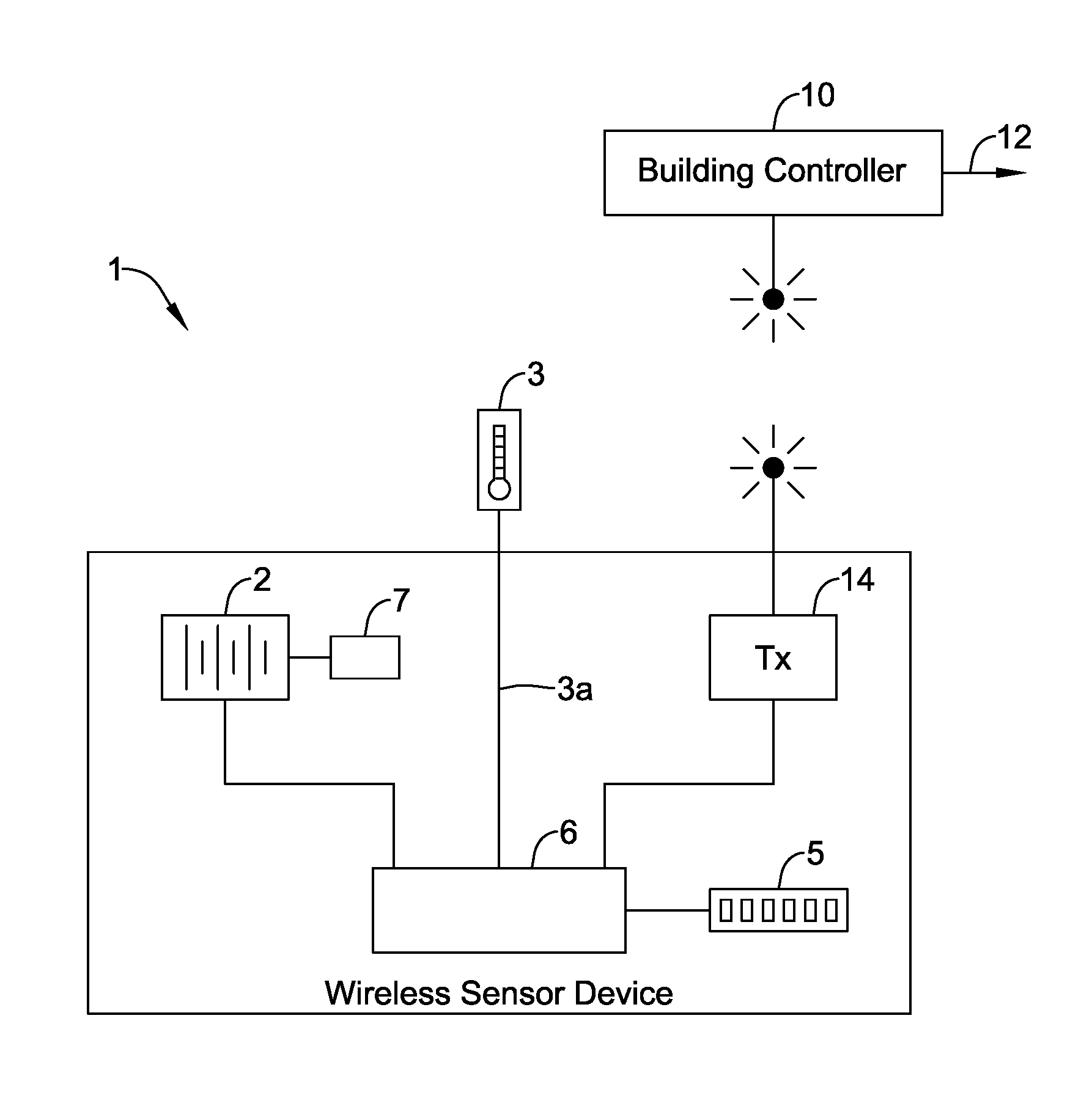
FIG. 1 is a schematic view of an illustrative but non-limiting wireless sensor device having a controller in wireless communication with a remotely located device.
While the disclosure is amenable to various modifications and alternative forms, specifics thereof have been shown by way of example in the drawing and will be described in detail. It should be understood, however, that the intention is not to limit aspects of the disclosure to the particular embodiments described. On the contrary, the intention is to cover all modifications, equivalents, and alternatives falling within the spirit and scope of the disclosure.
DESCRIPTION
The following description should be read with reference to the drawing. The description and drawing are meant to illustrative in nature. While a battery powered wireless sensor device is used as an example below, it is contemplated that the present disclosure can be applied to any suitable device, as desired. For instance, the disclosure may be applied to devices that are powered by a wall current or are plugged into other devices for power, rather than just battery powered. As another example, the disclosure may be applied to devices that control other devices, such as general purpose input/output (GPIO), rather than just sensor devices. In some cases, the disclosure may be applied to wireless building controllers such as wireless thermostats, wireless zone controllers, wireless equipment interface modules, wireless security system controllers, wireless building control actuators such as wireless damper and valve actuators, and/or any other suitable wireless building control device, as desired.
FIG. 1 is a schematic view of an illustrative but non-limiting wireless sensor device 1 in wireless communication with a remotely located device 10. In the example shown, the wireless sensor device 1 may operate on battery power and, as such, may implement various algorithms to help conserve battery power when possible. The wireless sensor device 1 may include a sensor 3, such as a temperature sensor, a humidity sensor, a pressure sensor, a flow sensor, a motion sensor, an acoustical sensor, a magnetic sensor, a contact sensor, a light sensor, and/or any other suitable sensor. The wireless sensor device 1 may sense an ambient condition (e.g. temperature, humidity, etc.) in or around the wireless sensor device 1. The wireless sensor device 1 may include a wireless transceiver 14 for wirelessly sending and receiving messages to/from a remotely located device 10, such as a remotely located building controller. In some instances, the remotely located device 10 may be a diagnostic or setup tool that may be used by a technician or installer to send one or more messages to the wireless sensor device 1.
In one example, the remotely located device 10 may be a building controller. The wireless sensor device 1 may send messages to the building controller that includes a measure related to the condition sensed by the sensor 3 of the wireless sensor device 1. The building controller may use the measure related to the sensed condition to determine and then send one or more control signals 12 to a building control system (not shown). In some instances, the building control system may be, for example, an HVAC system, a security system, a fire detection system, and/or any other suitable building control system as desired.
In the example shown in FIG. 1, the wireless sensor device 1 may include a battery 2, which may be rechargeable or replaceable. In general, it is desirable to lengthen the time between recharging or replacement of the battery 2. The wireless sensor device 1 also includes a sensor 3 that senses one or more conditions in or around the wireless sensor device 1, a wireless transceiver 14 for wirelessly sending and receiving messages to and/or from the remotely located device 10, and a memory 5 for storing one or more parameter values.
The illustrative wireless sensor device 1 of FIG. 1 also includes a controller 6. The controller 6 communicates with the battery 2, the sensor 3, the wireless transceiver 14 and the memory 5. With regard to the battery 2, the controller 6 may received power from, and in some cases, monitor the current flowing from the battery 2 and/or the voltage provided by the battery 2. In some cases, the controller 6 may determine an amount of life left in the battery 2. In some instances, the controller 6 may be programmed to operate differently depending on the amount of life left in the battery 2. For example, the controller may increase the time between when the sensed condition is transmitted to the remotely located device 10 after the amount of life left in the battery 2 falls below a threshold value. With regard to the sensor 3, the controller 6 may poll the sensor 3 at a particular time and may receive a reading from the sensor 3 in response. With regard to the wireless transceiver 14, the controller 6 may receive and interpret messages that arrive through the wireless transceiver 14, and may compose and transmit messages through the wireless transceiver 14. With regard to the memory 5, the controller 6 may store and retrieve particular parameter values, algorithms, and other data as needed.
In some cases, the controller 6 may be configured to switch the wireless sensor device 1 between a lower power sleep mode and a higher power awake mode. In the lower power sleep mode, the wireless sensor device 1 may not send or receive messages to/from the remotely located device 10 via the wireless transceiver 14. In the higher power awake mode, the controller 6 may be configured to send and/or receive one or more messages to/from the remotely located device 10 via the wireless transceiver 14. In some instances, the "lower power sleep mode" and the "higher power awake mode" discussed herein may be thought of as being a "quiet" mode and a "talking" mode, respectively, where being "quiet" can have the potential advantages of saving power, preserving wireless and/or wired channel capacity, and/or preventing unneeded processing of data.
In some instances, the one or more messages from the remotely located device 10 may specify a sleep algorithm that is to be used by the controller 6 to determine when to switch the wireless sensor device 1 between the lower power sleep mode and the higher power awake mode during subsequent operation of the wireless sensor device 1. The controller 6 may be configured to subsequently switch between the lower power sleep mode and the higher power awake mode in accordance with the sleep algorithm specified by the one or more messages from the remotely located device 10.
In some cases, the sensor 3 may provide a sensor signal 3a that encodes a measure related to the sensed condition in or around the wireless sensor device 1. In some cases, the sleep algorithm may use, at least in part, the sensor signal 3a to determine when to switch the wireless sensor device 1 between the lower power sleep mode and the higher power awake mode. Alternatively, or in addition, the sleep algorithm may use a measure related to a rate of change of the sensor signal 3a to determine when to switch the wireless sensor device 1 between the lower power sleep mode and the higher power awake mode. The one or more messages may identify a desired sleep algorithm. It is contemplated that the sleep mode may be communicated and switched even while the wireless sensor device 1 and building controller 10 are on-line and actively controlling a building control system.
In some cases, the wireless sensor device 1 may include a battery condition monitor 7 that provides a measure related to the current charge condition of the battery 2. In some cases, the sleep algorithm may use, at least in part, a measure related to the current charge condition of the battery 2 to determine when to switch the wireless sensor device between the lower power sleep mode and the higher power awake mode. In some instances, the sleep algorithm may increase the time the wireless sensor device 1 is in the lower power sleep mode relative to the higher power awake mode as the condition of the battery 2 deteriorates over time and/or crosses a threshold value.
In some cases, the controller 6, through the transceiver 4, may establish communication with the remotely located device 10 via a wireless link and/or wireless network. In some cases, the sleep algorithm may keep the wireless sensor device 1 in the higher power awake mode until the controller 6 establishes communication with the remotely located device 10 via the wireless link or wireless network.
In some instances, the controller 6 may be configured to receive one or more parameter setting messages from the remotely located device 10 via the wireless transceiver 14 in the higher power awake mode. The one or more parameter setting messages may provide one or more parameter values, which may be stored in memory 5. In some cases, the controller 6 may determine when to switch between the lower power sleep mode and the higher power awake mode based on one or more sleep algorithms that read up or otherwise are dependent upon one or more of the parameter values. For example, and in some instances, at least one of the one or more sleep algorithms uses a sleep interval that corresponds to a sleep time between each of two or more successive higher power awake modes. In some cases, at least one of the parameter values of the parameter setting messages may correspond to the sleep interval. In another example, at least one of the one or more sleep algorithms may use a sleep interval for a set number of sleep periods. The parameter values of the parameter setting messages may set one or both of the sleep interval (e.g. 10 seconds) or the number of sleep periods (28800 sleep periods, which would set the sleep interval to be 10 seconds for the next 8 hours). New parameter values may be sent via one or more subsequent parameter setting messages to set a different sleep interval and/or a different period of time, as desired.
In some cases, the remotely located device 10 may be a building controller (e.g. HVAC Controller) that stores and executes a programmable schedule such as a programmable temperature schedule. The temperature schedule may include a more energy efficient set point during a scheduled unoccupied time period and a less energy efficient set point during a scheduled occupied time period. The HVAC controller may send one or more first parameter setting messages to the wireless sensor device 1 that specify a first sleep interval in response to entering an unoccupied time period of the schedule, and may send one or more second parameter setting messages that specify a second sleep interval in response to entering a subsequent occupied time period of the schedule, even while the wireless sensor device 1 and the HVAC controller are on-line and actively controlling a building control system (e.g. HVAC system).
In some cases, the controller 6 of the wireless sensor device 1 may include a rules based engine that controls the operation of at least part of the wireless sensor device 1 according to a number of rules. When so provided, the wireless sensor device 1 may receive one or more messages from the remotely located device 10 via the wireless transceiver 14 that specify one or more rules. The rules may be stored in the memory 5. The rules based engine of the controller 6 may read up the rules from the memory 5 and control the operation of at least part of the wireless sensor device 1 according to the received rules. In some cases, the one or more rules may define, at least in part, a sleep algorithm that is used to determine when to switch the wireless sensor device 1 between the lower power sleep mode and the higher power awake mode. In some cases, the transceiver 4 communicates with the remotely located device via a wireless network that includes a communication protocol that requires an acknowledgement to acknowledge a communication across the wireless network. The one or more rules may define how long to wait for an acknowledgement. In some cases, the controller 6 is configured to transmit a measure related to the one or more sensed conditions via the wireless transceiver 14. The one or more rules may define, at least in part, how often to transmit the measure. In some cases, the wireless sensor device 1 may include a battery condition monitor 7 that provides a measure related to the current charge condition of the battery 2. The one or more rules may define, at least in part, how often to transmit the measure based on the current charge condition of the battery 2. Use of a rules based engine may simplify the definition, transmission and subsequent programming of the wireless sensor device 1.
An illustrative method for operating a wireless sensor device 1 may include wirelessly receiving one or more first messages from the remotely located device 10 via the wireless transceiver 14, wherein the one or more first messages may specify a first sleep algorithm that is used by the controller 6 to determine when to switch the wireless sensor device 1 between the lower power sleep mode and the higher power awake mode. The method may then execute the first sleep algorithm specified by the one or more first messages from the remotely located device 10 until one or more subsequent second messages are received from the remotely located device 10 that specify a second sleep algorithm, whereupon, the second sleep algorithm specified by the one or more subsequent second messages may be executed in place of the first sleep algorithm.
In some cases, after receiving the one or more second messages, the wireless sensor device 1 may wirelessly receive one or more third messages from the remotely located device 10 via the wireless transceiver 14. The one or more third messages may specify a third sleep algorithm that is used by the controller 6 to determine when to switch the wireless sensor device between the lower power sleep mode and the higher power awake mode. The controller may then execute the third sleep algorithm specified by the one or more third messages from the remotely located device 10 in place of the second sleep algorithm. In some cases, the first sleep algorithm allows more sleep time than the second sleep algorithm.
Having thus described several illustrative embodiments of the present disclosure, those of skill in the art will readily appreciate that yet other embodiments may be made and used within the scope of the claims hereto attached. It will be understood, however, that this disclosure is, in many respect, only illustrative. Changes may be made in details, particularly in matters of shape, size, arrangement of parts, and exclusion and order of steps, without exceeding the scope of the disclosure. The disclosure's scope is, of course, defined in the language in which the appended claims are expressed.
* * * * *
References
D00000
D00001
XML
uspto.report is an independent third-party trademark research tool that is not affiliated, endorsed, or sponsored by the United States Patent and Trademark Office (USPTO) or any other governmental organization. The information provided by uspto.report is based on publicly available data at the time of writing and is intended for informational purposes only.
While we strive to provide accurate and up-to-date information, we do not guarantee the accuracy, completeness, reliability, or suitability of the information displayed on this site. The use of this site is at your own risk. Any reliance you place on such information is therefore strictly at your own risk.
All official trademark data, including owner information, should be verified by visiting the official USPTO website at www.uspto.gov. This site is not intended to replace professional legal advice and should not be used as a substitute for consulting with a legal professional who is knowledgeable about trademark law.