Electric powered pump down
Oehring , et al. Sept
U.S. patent number 10,408,030 [Application Number 15/653,028] was granted by the patent office on 2019-09-10 for electric powered pump down. This patent grant is currently assigned to U.S. Well Services, LLC. The grantee listed for this patent is U.S. Well Services, LLC. Invention is credited to Brandon N. Hinderliter, Jared Oehring.


| United States Patent | 10,408,030 |
| Oehring , et al. | September 10, 2019 |
Electric powered pump down
Abstract
A method of operations in a subterranean formation, including driving a pump with an electrically powered motor to pressurize fluid, inserting a tool into a wellbore that intersects the formation, and directing the pressurized fluid into the wellbore above the tool to push the tool into the wellbore.
| Inventors: | Oehring; Jared (Houston, TX), Hinderliter; Brandon N. (Houston, TX) | ||||||||||
|---|---|---|---|---|---|---|---|---|---|---|---|
| Applicant: |
|
||||||||||
| Assignee: | U.S. Well Services, LLC
(Houston, TX) |
||||||||||
| Family ID: | 57882430 | ||||||||||
| Appl. No.: | 15/653,028 | ||||||||||
| Filed: | July 18, 2017 |
Prior Publication Data
| Document Identifier | Publication Date | |
|---|---|---|
| US 20170314380 A1 | Nov 2, 2017 | |
Related U.S. Patent Documents
| Application Number | Filing Date | Patent Number | Issue Date | ||
|---|---|---|---|---|---|
| 15291842 | Oct 12, 2016 | 9745840 | |||
| 15202085 | Jul 5, 2016 | ||||
| 13679689 | Aug 9, 2016 | 9410410 | |||
| 62242173 | Oct 15, 2015 | ||||
| Current U.S. Class: | 1/1 |
| Current CPC Class: | F04B 47/02 (20130101); F04B 17/03 (20130101); F04B 19/22 (20130101); F04B 49/065 (20130101); H02P 23/00 (20130101); F02C 3/22 (20130101); F01D 15/08 (20130101); F04B 49/20 (20130101); E21B 23/08 (20130101); F04B 23/04 (20130101); E21B 43/267 (20130101); F01D 15/10 (20130101); E21B 43/26 (20130101); F05D 2220/32 (20130101) |
| Current International Class: | E21B 23/08 (20060101); E21B 43/26 (20060101); H02P 23/00 (20160101); F01D 15/10 (20060101); E21B 43/267 (20060101); F01D 15/08 (20060101); F04B 49/06 (20060101); F04B 23/04 (20060101); F04B 47/02 (20060101); F02C 3/22 (20060101); F04B 49/20 (20060101); F04B 19/22 (20060101); F04B 17/03 (20060101) |
References Cited [Referenced By]
U.S. Patent Documents
| 1671436 | May 1928 | Melott |
| 2004077 | June 1935 | McCartney |
| 2183364 | December 1939 | Bailey |
| 2220622 | November 1940 | Aitken |
| 2248051 | July 1941 | Armstrong |
| 2753940 | July 1956 | Bonner |
| 3061039 | October 1962 | Peters |
| 3066503 | December 1962 | Fleming |
| 3334495 | August 1967 | Jensen |
| 3722595 | March 1973 | Kiel |
| 3764233 | October 1973 | Strickland |
| 3773140 | November 1973 | Mahajan |
| 3837179 | September 1974 | Barth |
| 3849662 | November 1974 | Blaskowski |
| 3881551 | May 1975 | Terry |
| 4037431 | July 1977 | Sugimoto |
| 4100822 | July 1978 | Rosman |
| 4151575 | April 1979 | Hogue |
| 4226299 | October 1980 | Hansen |
| 4265266 | May 1981 | Kierbow et al. |
| 4432064 | February 1984 | Barker |
| 4442665 | April 1984 | Fick et al. |
| 4456092 | June 1984 | Kubozuka |
| 4506982 | March 1985 | Smithers et al. |
| 4512387 | April 1985 | Rodriguez |
| 4529887 | July 1985 | Johnson |
| 4538916 | September 1985 | Zimmerman |
| 4676063 | June 1987 | Goebel et al. |
| 4793386 | December 1988 | Sloan |
| 4845981 | July 1989 | Pearson |
| 4922463 | May 1990 | Del Zotto et al. |
| 5006044 | April 1991 | Walker, Sr. |
| 5025861 | June 1991 | Huber et al. |
| 5130628 | July 1992 | Owen |
| 5131472 | July 1992 | Dees et al. |
| 5189388 | February 1993 | Mosley |
| 5422550 | June 1995 | McClanahan |
| 5548093 | August 1996 | Sato |
| 5590976 | January 1997 | Kilheffer et al. |
| 5655361 | August 1997 | Kishi |
| 5736838 | April 1998 | Dove et al. |
| 5790972 | August 1998 | Kohlenberger |
| 5865247 | February 1999 | Paterson |
| 5879137 | March 1999 | Yie |
| 5894888 | April 1999 | Wiemers |
| 5907970 | June 1999 | Havlovick et al. |
| 6138764 | October 2000 | Scarsdale et al. |
| 6142878 | November 2000 | Barin |
| 6164910 | December 2000 | Mayleben |
| 6202702 | March 2001 | Ohira |
| 6208098 | March 2001 | Kume |
| 6254462 | July 2001 | Kelton |
| 6271637 | August 2001 | Kushion |
| 6315523 | November 2001 | Mills |
| 6477852 | November 2002 | Dodo |
| 6491098 | December 2002 | Dallas |
| 6529135 | March 2003 | Bowers et al. |
| 6776227 | August 2004 | Beida |
| 6802690 | October 2004 | Han |
| 6808303 | October 2004 | Fisher |
| 6931310 | August 2005 | Shimizu et al. |
| 7104233 | September 2006 | Ryczek et al. |
| 7170262 | January 2007 | Pettigrew |
| 7173399 | February 2007 | Sihler |
| 7312593 | December 2007 | Streicher et al. |
| 7336514 | February 2008 | Amarillas |
| 7445041 | November 2008 | O'Brien |
| 7494263 | February 2009 | Dykstra et al. |
| 7500642 | March 2009 | Cunningham |
| 7525264 | April 2009 | Dodge |
| 7563076 | July 2009 | Brunet |
| 7675189 | March 2010 | Grenier |
| 7683499 | March 2010 | Saucier |
| 7717193 | May 2010 | Egilsson et al. |
| 7755310 | July 2010 | West et al. |
| 7807048 | October 2010 | Collette |
| 7845413 | December 2010 | Shampine et al. |
| 7977824 | July 2011 | Halen et al. |
| 8037936 | October 2011 | Neuroth |
| 8054084 | November 2011 | Schulz et al. |
| 8083504 | December 2011 | Williams |
| 8096891 | January 2012 | Lochtefeld |
| 8139383 | March 2012 | Efraimsson |
| 8146665 | April 2012 | Neal |
| 8154419 | April 2012 | Daussin et al. |
| 8232892 | July 2012 | Overholt et al. |
| 8261528 | September 2012 | Chillar |
| 8272439 | September 2012 | Strickland |
| 8310272 | November 2012 | Quarto |
| 8354817 | January 2013 | Yeh et al. |
| 8474521 | July 2013 | Kajaria |
| 8534235 | September 2013 | Chandler |
| 8573303 | November 2013 | Kerfoot |
| 8596056 | December 2013 | Woodmansee |
| 8616274 | December 2013 | Belcher et al. |
| 8692408 | April 2014 | Zhang et al. |
| 8727068 | May 2014 | Bruin |
| 8760657 | June 2014 | Pope |
| 8774972 | July 2014 | Rusnak et al. |
| 8789601 | July 2014 | Broussard |
| 8807960 | August 2014 | Stephenson |
| 8838341 | September 2014 | Kumano |
| 8851860 | October 2014 | |
| 8857506 | October 2014 | Stone, Jr. |
| 8899940 | December 2014 | Laugemors |
| 8905056 | December 2014 | Kendrick |
| 8905138 | December 2014 | Lundstedt et al. |
| 8997904 | April 2015 | Cryer |
| 9018881 | April 2015 | Mao et al. |
| 9051822 | June 2015 | Ayan |
| 9067182 | June 2015 | Nichols |
| 9103193 | August 2015 | Coll |
| 9121257 | September 2015 | Coli et al. |
| 9140110 | September 2015 | Coli et al. |
| 9160168 | October 2015 | Chapel |
| 9175554 | November 2015 | Watson |
| 9206684 | December 2015 | Parra |
| 9322239 | April 2016 | Angeles Boza et al. |
| 9366114 | June 2016 | Coli et al. |
| 9410410 | August 2016 | Broussard et al. |
| 9450385 | September 2016 | Kristensen |
| 9458687 | October 2016 | Hallundbaek |
| 9475020 | October 2016 | Coli et al. |
| 9475021 | October 2016 | Coli et al. |
| 9534473 | January 2017 | Morris et al. |
| 9562420 | February 2017 | Morris et al. |
| 9587649 | March 2017 | Oehring |
| 9611728 | April 2017 | Oehring |
| 9650879 | May 2017 | Broussard et al. |
| 9738461 | August 2017 | DeGaray |
| 9745840 | August 2017 | Oehring et al. |
| 9863228 | January 2018 | Shampine et al. |
| 2002/0169523 | November 2002 | Ross |
| 2003/0138327 | July 2003 | Jones et al. |
| 2004/0040746 | March 2004 | Niedermayr |
| 2004/0102109 | May 2004 | Cratty |
| 2005/0116541 | June 2005 | Seiver |
| 2005/0274508 | December 2005 | Folk |
| 2006/0052903 | March 2006 | Bassett |
| 2006/0260331 | November 2006 | Andreychuk |
| 2007/0131410 | June 2007 | Hill |
| 2007/0187163 | August 2007 | Cone |
| 2007/0201305 | August 2007 | Heilman et al. |
| 2007/0226089 | September 2007 | DeGaray et al. |
| 2007/0277982 | December 2007 | Shampine |
| 2007/0278140 | December 2007 | Mallet et al. |
| 2008/0112802 | May 2008 | Orlando |
| 2008/0137266 | June 2008 | Jensen |
| 2008/0208478 | August 2008 | Ella et al. |
| 2008/0217024 | September 2008 | Moore |
| 2008/0236818 | October 2008 | Dykstra |
| 2008/0264640 | October 2008 | Eslinger |
| 2008/0264649 | October 2008 | Crawford |
| 2009/0045782 | February 2009 | Datta |
| 2009/0065299 | March 2009 | Vito |
| 2009/0078410 | March 2009 | Krenek et al. |
| 2009/0090504 | April 2009 | Weightman |
| 2009/0093317 | April 2009 | Kajiwara et al. |
| 2009/0095482 | April 2009 | Surjaatmadja |
| 2009/0153354 | June 2009 | Daussin et al. |
| 2009/0188181 | July 2009 | Forbis |
| 2009/0200035 | August 2009 | Bjerkreim et al. |
| 2009/0260826 | October 2009 | Sherwood |
| 2009/0308602 | December 2009 | Bruins et al. |
| 2010/0000508 | January 2010 | Chandler |
| 2010/0019574 | January 2010 | Baldassarre |
| 2010/0051272 | March 2010 | Loree et al. |
| 2010/0101785 | April 2010 | Khvoshchev |
| 2010/0132949 | June 2010 | DeFosse et al. |
| 2010/0146981 | June 2010 | Motakef |
| 2010/0172202 | July 2010 | Borgstadt |
| 2010/0200224 | August 2010 | Nguete |
| 2010/0250139 | September 2010 | Hobbs et al. |
| 2010/0293973 | November 2010 | Erickson |
| 2010/0303655 | December 2010 | Scekic |
| 2010/0322802 | December 2010 | Kugelev |
| 2011/0005757 | January 2011 | Hebert |
| 2011/0017468 | January 2011 | Birch et al. |
| 2011/0061855 | March 2011 | Case et al. |
| 2011/0085924 | April 2011 | Shampine |
| 2011/0166046 | July 2011 | Weaver |
| 2011/0247878 | October 2011 | Rasheed |
| 2011/0272158 | November 2011 | Neal |
| 2012/0018016 | January 2012 | Gibson |
| 2012/0085541 | April 2012 | Love et al. |
| 2012/0127635 | May 2012 | Grindeland |
| 2012/0205301 | August 2012 | McGuire et al. |
| 2012/0205400 | August 2012 | DeGaray et al. |
| 2012/0232728 | September 2012 | Karimi |
| 2012/0255734 | October 2012 | Coli et al. |
| 2013/0009469 | January 2013 | Gillett |
| 2013/0025706 | January 2013 | DeGaray et al. |
| 2013/0175038 | July 2013 | Conrad |
| 2013/0175039 | July 2013 | Guidry |
| 2013/0199617 | August 2013 | DeGaray et al. |
| 2013/0233542 | September 2013 | Shampine |
| 2013/0306322 | November 2013 | Sanborn et al. |
| 2013/0341029 | December 2013 | Roberts et al. |
| 2013/0343858 | December 2013 | Flusche |
| 2014/0000899 | January 2014 | Nevison |
| 2014/0010671 | January 2014 | Cryer et al. |
| 2014/0054965 | February 2014 | Jain |
| 2014/0095114 | April 2014 | Thomeer |
| 2014/0096974 | April 2014 | Coli |
| 2014/0124162 | May 2014 | Leavitt |
| 2014/0138079 | May 2014 | Broussard et al. |
| 2014/0174717 | June 2014 | Broussard et al. |
| 2014/0246211 | September 2014 | Guidry |
| 2014/0251623 | September 2014 | Lestz et al. |
| 2014/0277772 | September 2014 | Lopez |
| 2014/0290768 | October 2014 | Randle |
| 2014/0379300 | December 2014 | Devine et al. |
| 2015/0068724 | March 2015 | Coli et al. |
| 2015/0068754 | March 2015 | Coli et al. |
| 2015/0075778 | March 2015 | Walters |
| 2015/0083426 | March 2015 | Lesko |
| 2015/0097504 | April 2015 | Lamascus |
| 2015/0114652 | April 2015 | Lestz |
| 2015/0144336 | May 2015 | Hardin et al. |
| 2015/0159911 | June 2015 | Holt |
| 2015/0175013 | June 2015 | Cryer et al. |
| 2015/0176386 | June 2015 | Castillo et al. |
| 2015/0211524 | July 2015 | Broussard |
| 2015/0217672 | August 2015 | Shampine |
| 2015/0225113 | August 2015 | Lungu |
| 2015/0252661 | September 2015 | Glass |
| 2015/0300145 | October 2015 | Coli et al. |
| 2015/0314225 | November 2015 | Coli et al. |
| 2015/0330172 | November 2015 | Allmaras |
| 2016/0032703 | February 2016 | Broussard et al. |
| 2016/0102537 | April 2016 | Lopez |
| 2016/0105022 | April 2016 | Oehring |
| 2016/0208592 | April 2016 | Oehring |
| 2016/0160889 | June 2016 | Hoffman et al. |
| 2016/0177675 | June 2016 | Morris et al. |
| 2016/0177678 | June 2016 | Morris |
| 2016/0186531 | June 2016 | Harkless et al. |
| 2016/0208593 | July 2016 | Coli et al. |
| 2016/0208594 | July 2016 | Coli et al. |
| 2016/0208595 | July 2016 | Tang |
| 2016/0221220 | August 2016 | Paige |
| 2016/0230524 | August 2016 | Dumoit |
| 2016/0230525 | August 2016 | Lestz et al. |
| 2016/0258267 | September 2016 | Payne et al. |
| 2016/0273328 | September 2016 | Oehring |
| 2016/0290114 | October 2016 | Oehring |
| 2016/0312108 | October 2016 | Lestz et al. |
| 2016/0319650 | November 2016 | Oehring |
| 2016/0326854 | November 2016 | Broussard |
| 2016/0326855 | November 2016 | Coli et al. |
| 2016/0341281 | November 2016 | Brunvold et al. |
| 2016/0348479 | December 2016 | Oehring |
| 2016/0349728 | December 2016 | Oehring |
| 2016/0369609 | December 2016 | Morris et al. |
| 2017/0021318 | January 2017 | McIver et al. |
| 2017/0022788 | January 2017 | Oehring et al. |
| 2017/0022807 | January 2017 | Dursun |
| 2017/0028368 | February 2017 | Oehring et al. |
| 2017/0030177 | February 2017 | Oehring et al. |
| 2017/0030178 | February 2017 | Oehring et al. |
| 2017/0036178 | February 2017 | Coli et al. |
| 2017/0037717 | February 2017 | Oehring |
| 2017/0037718 | February 2017 | Coli et al. |
| 2017/0051732 | February 2017 | Hemandez et al. |
| 2017/0096885 | April 2017 | Oehring |
| 2017/0104389 | April 2017 | Morris et al. |
| 2017/0114625 | April 2017 | Norris |
| 2017/0218843 | August 2017 | Oehring et al. |
| 2017/0222409 | August 2017 | Oehring et al. |
| 2017/0226842 | August 2017 | Omont et al. |
| 2017/0241221 | August 2017 | Seshadri |
| 2017/0259227 | September 2017 | Morris et al. |
| 2017/0292513 | October 2017 | Haddad |
| 2017/0313499 | November 2017 | Hughes et al. |
| 2017/0314380 | November 2017 | Oehring |
| 2017/0328179 | November 2017 | Dykstra |
| 2017/0369258 | December 2017 | DeGaray |
| 2018/0038216 | February 2018 | Zhang |
| 2018/0320483 | November 2018 | Zhang |
| 2019/0003329 | January 2019 | Morris |
| 2007340913 | Jul 2008 | AU | |||
| 2955706 | Oct 2012 | CA | |||
| 2966672 | Oct 2012 | CA | |||
| 2833711 | May 2014 | CA | |||
| 2964593 | Oct 2017 | CA | |||
| 201687513 | Dec 2010 | CN | |||
| 101977016 | Feb 2011 | CN | |||
| 202023547 | Nov 2011 | CN | |||
| 102602322 | Jul 2012 | CN | |||
| 2004264589 | Sep 2004 | JP | |||
| 2016/144939 | Sep 2016 | WO | |||
| 2016/160458 | Oct 2016 | WO | |||
Other References
|
Non-Final Office Action dated Oct. 6, 2017 in related U.S. Appl. No. 14/881,535. cited by applicant . Non-Final Office Action dated Nov. 29, 2017 in related U.S. Appl. No. 15/145,414. cited by applicant . Non-Final Office Action dated Nov. 13, 2017 in related U.S. Appl. No. 15/644,487. cited by applicant . Canadian Office Action dated Jun. 22, 2018 in related Canadian Patent Application No. 2,886,697. cited by applicant . Office Action dated Jul. 25, 2018 in related U.S. Appl. No. 15/644,487. cited by applicant . Office Action dated Dec. 12, 2018 in related U.S. Appl. No. 16/160,708. cited by applicant . International Search Report and Written Opinion dated Jan. 2, 2019 in related PCT Patent Application No. PCT/US18/54542. cited by applicant . International Search Report and Written Opinion dated Jan. 2, 2019 in related PCT Patent Application No. PCT/US18/54548. cited by applicant . International Search Report and Written Opinion dated Dec. 31, 2018 in related PCT Patent Application No. PCT/US18/55913. cited by applicant . International Search Report and Written Opinion dated Jan. 4, 2019 in related PCT Patent Application No. PCT/US18/57539. cited by applicant . UK Power Networks--Transformers to Supply Heat to Tate Modern--from Press Releases May 16, 2013. cited by applicant . Non-Final Office Action issued in corresponding U.S. Appl. No. 15/293,681 dated Feb. 16, 2017. cited by applicant . Non-Final Office Action issued in corresponding U.S. Appl. No. 15/294,349 dated Mar. 14, 2017. cited by applicant . Final Office Action issued in corresponding U.S. Appl. No. 15/145,491 dated Jan. 20, 2017. cited by applicant . Non-Final Office Action issued in corresponding U.S. Appl. No. 15/145,443 dated Feb. 7, 2017. cited by applicant . Notice of Allowance issued in corresponding U.S. Appl. No. 15/217,040 dated Mar. 28, 2017. cited by applicant . Notice of Allowance issued in corresponding U.S. Appl. No. 14/622,532 dated Mar. 27, 2017. cited by applicant . Non-Final Office Action issued in corresponding U.S. Appl. No. 15/291,842 dated Jan. 6, 2017. cited by applicant . Final Office Action issued in corresponding U.S. Appl. No. 14/622,532 dated Dec. 7, 2016. cited by applicant . Non-Final Office Action issued in corresponding U.S. Appl. No. 14/622,532 dated May 17, 2016. cited by applicant . Final Office Action issued in corresponding U.S. Appl. No. 14/622,532 dated Dec. 21, 2015. cited by applicant . Non-Final Office Action issued in corresponding U.S. Appl. No. 14/622,532 dated Aug. 5, 2015. cited by applicant . Non-Final Office Action issued in corresponding U.S. Appl. No. 15/145,491 dated Sep. 12, 2016. cited by applicant . Non-Final Office Action issued in corresponding U.S. Appl. No. 15/217,040 dated Nov. 29, 2016. cited by applicant . Non-Final Office Action issued in corresponding U.S. Appl. No. 15/235,788 dated Dec. 14, 2016. cited by applicant . Non-Final Office Action issued in corresponding U.S. Appl. No. 15/145,491 dated May 15, 2017. cited by applicant . Non-Final Office Action dated Oct. 4, 2018 in related U.S. Appl. No. 15/217,081. cited by applicant . International Search Report and Written Opinion dated Sep. 19, 2018 in related PCT Patent Application No. PCT/US2018/040683. cited by applicant . Canadian Office Action dated Sep. 28, 2018 in related Canadian Patent Application No. 2,945,281. cited by applicant . Non-Final Office Action dated Feb. 12, 2019 in related U.S. Appl. No. 16/170,695. cited by applicant . International Search Report and Written Opinion dated Feb. 15, 2019 in related PCT Application No. PCT/US18/63977. cited by applicant . Non-Final Office Action dated Feb. 25, 2019 in related U.S. Appl. No. 16/210,749. cited by applicant . International Search Report and Written Opinion dated Mar. 5, 2019 in related PCT Application No. PCT/US18/63970. cited by applicant . Non-Final Office Action dated Mar. 6, 2019 in related U.S. Appl. No. 15/183,387. cited by applicant . Office Action dated Mar. 1, 2019 in related Canadian Patent Application No. 2,943,275. cited by applicant . Office Action dated Jan. 30, 2019 in related Canadian Patent Application No. 2,936,997. cited by applicant . Non-Final Office Action issued in corresponding U.S. Appl. No. 15/486,970 dated Jun. 22, 2017. cited by applicant . Non-Final Office Action issued in corresponding U.S. Appl. No. 15/487,656 dated Jun. 23, 2017. cited by applicant . Non-Final Office Action issued in corresponding U.S. Appl. No. 15/487,694 dated Jun. 26, 2017. cited by applicant . Final Office Action issued in corresponding U.S. Appl. No. 15/294,349 dated Jul. 6, 2017. cited by applicant . Non-Final Office Action issued in corresponding U.S. Appl. No. 14/884,363 dated Sep. 5, 2017. cited by applicant . Final Office Action issued in corresponding U.S. Appl. No. 15/145,491 dated Sep. 6, 2017. cited by applicant . Canadian Office Action dated Mar. 2, 2018 in related Canadian Patent Application No. 2,833,711. cited by applicant . Office Action dated Apr. 10, 2018 in related U.S. Appl. No. 15/294,349. cited by applicant . Office Action dated Apr. 2, 2018 in related U.S. Appl. No. 15/183,387. cited by applicant . Office Action dated May 29, 2018 in related U.S. Appl. No. 15/235,716. cited by applicant . Canadian Office Action dated Apr. 18, 2018 in related Canadian Patent Application No. 2,928,711. cited by applicant . International Search Report and Written Opinion dated Apr. 10, 2019 in corresponding PCT Application No. PCT/US2019/016635. cited by applicant . Notice of Allowance dated May 1, 2019 in corresponding U.S. Appl. No. 15/202,085. cited by applicant . Schlumberger, "Jet Manual 23, Fracturing Pump Units, SPF/SPS-343, Version 1.0," Jan. 31, 2007, 68 pages. cited by applicant . Stewart & Stevenson, "Stimulation Systems," 2007, 20 pages. cited by applicant . Luis Gamboa, "Variable Frequency Drives in Oil and Gas Pumping Systems," Dec. 17, 2011, 5 pages. cited by applicant . "Griswold Model 811 Pumps: Installation, Operation and Maintenance Manual, ANSI Process Pump," 2010, 60 pages. cited by applicant. |
Primary Examiner: Thompson; Kenneth L
Attorney, Agent or Firm: Hogan Lovells US LLP
Parent Case Text
CROSS REFERENCE TO RELATED APPLICATIONS
This application is a continuation of U.S. patent application Ser. No. 15/291,842, filed on Oct. 12, 2016, which issued as U.S. Pat. No. 9,745,840 on Aug. 29, 2017, and claims priority to and the benefit of U.S. Provisional Application Ser. No. 62/242,173, filed Oct. 15, 2015, and is a continuation-in-part of, and claims priority to and the benefit of U.S. patent application Ser. No. 15/202,085, filed Jul. 5, 2016, and which claims priority to and the benefit of U.S. patent application Ser. No. 13/679,689, filed Nov. 16,2012, which issued as U.S. Pat. No. 9,410,410 on Aug. 9, 2016; the full disclosures of which are hereby incorporated by reference herein for all purposes.
Claims
What is claimed is:
1. A method of operations in a subterranean formation, the method comprising: driving a pump with an electrically powered motor to pressurize fluid; inserting a tool into a wellbore that intersects the formation; pressurizing fluid upstream of the pump to form a boost fluid; directing the boost fluid to the pump; and directing the pressurized fluid downstream of the pump and into the wellbore upstream of the tool to push the tool into the wellbore.
2. The method of claim 1, further comprising urging the tool into the wellbore with the pressurized fluid until the tool reaches a predetermined location in the formation.
3. The method of claim 1, wherein the tool comprises a perforating gun.
4. The method of claim 1, wherein the wellbore comprises a first wellbore, and wherein the pressurized fluid is simultaneously directed to a second wellbore that also intersects the subterranean formation.
5. The method of claim 4, wherein hydraulic fracturing is performed in the second wellbore.
6. The method of claim 5, wherein the pump comprises a first pump and a second pump, and wherein fluid pressurized by the first pump is directed into the first wellbore to push the tool into the first wellbore, and fluid pressurized by the second pump is directed into the second wellbore to use in hydraulic fracturing.
7. The method of claim 1, wherein the boost fluid is pressurized via an electric blender.
8. The method of claim 1, wherein electricity that powers the motor is generated with a generator that is proximate the electric motor.
9. The method of claim 8, wherein a wireline system is powered by the electricity.
10. A method of inserting a tool in a subterranean formation, the method comprising: positioning a trailer having a pump driven by an electric motor at a well site; positioning a second trailer having a boost pump at the well site; pressurizing fluid with the boost pump to form a boost fluid; directing the boost fluid to the pump; and driving the tool into the subterranean formation via the pump.
11. The method of claim 10, further comprising generating electricity by a turbine generator to power the electric motor.
12. The method of claim 10, further comprising positioning a sand conveyer and hydration unit at the well site.
13. The method of claim 10, further comprising using a first fluid pressurized by the pump to fracture the formation, and using a second fluid that is pressurized by the pump in a pump down operation.
14. The method of claim 13, wherein the first fluid is directed to a first wellbore that intersects the formation, and the second fluid is directed to a second wellbore that intersects the formation.
Description
BACKGROUND OF THE INVENTION
1. Field of Invention
The present disclosure relates to operations in a subterranean formations. In particular, the present disclosure relates to a system that uses fluid pressurized by electrically powered pumps for fracturing and for pump down operations.
2. Description of Prior Art
Hydraulic fracturing is a technique used to stimulate production from some hydrocarbon producing wells. The technique usually involves injecting fluid into a wellbore at a pressure sufficient to generate fissures in the formation surrounding the wellbore. Typically the pressurized fluid is injected into a portion of the wellbore that is pressure isolated from the remaining length of the wellbore so that fracturing is limited to a designated portion of the formation. The fracturing fluid slurry, whose primary component is usually water, includes proppant (such as sand or ceramic) that migrate into the fractures with the fracturing fluid slurry and remain to prop open the fractures after pressure is no longer applied to the wellbore. A primary fluid for the slurry other than water, such as nitrogen, carbon dioxide, foam (nitrogen and water), diesel, or other fluids is sometimes used as the primary component instead of water. Typically hydraulic fracturing fleets include a data van unit, blender unit, hydration unit, chemical additive unit, hydraulic fracturing pump unit, sand equipment, and other equipment.
Traditionally, the fracturing fluid slurry has been pressurized on surface by high pressure pumps powered by diesel engines. To produce the pressures required for hydraulic fracturing, the pumps and associated engines have substantial volume and mass. Heavy duty trailers, skids, or trucks are required for transporting the large and heavy pumps and engines to sites where wellbores are being fractured. Each hydraulic fracturing pump is usually composed of a power end and a fluid end. The hydraulic fracturing pump also generally contains seats, valves, a spring, and keepers internally. These parts allow the hydraulic fracturing pump to draw in low pressure fluid slurry (approximately 100 psi) and discharge the same fluid slurry at high pressures (over 10,000 psi). Recently electrical motors controlled by variable frequency drives have been introduced to replace the diesel engines and transmission, which greatly reduces the noise, emissions, and vibrations generated by the equipment during operation, as well as its size footprint.
On each separate unit, a closed circuit hydraulic fluid system is often used for operating auxiliary portions of each type of equipment. These auxiliary components may include dry or liquid chemical pumps, augers, cooling fans, fluid pumps, valves, actuators, greasers, mechanical lubrication, mechanical cooling, mixing paddles, landing gear, and other needed or desired components. This hydraulic fluid system is typically separate and independent of the main hydraulic fracturing fluid slurry that is being pumped into the wellbore.
SUMMARY OF THE INVENTION
Certain embodiments of the present technology provide a method of operations in a subterranean formation. The method includes driving a pump with an electrically powered motor to pressurize fluid, inserting a tool into a wellbore that intersects the formation, and directing the pressurized fluid into the wellbore above the tool to push the tool into the wellbore. In some embodiments, the method can further include urging the tool into the wellbore with the pressurized fluid until the tool reaches a predetermined location in the formation. In addition, the tool can be a perforating gun.
According to some embodiments, the wellbore can include a first wellbore, wherein the pressurized fluid is simultaneously directed to a second wellbore that also intersects the subterranean formation. Hydraulic fracturing can be performed in the second wellbore. Furthermore, the pump can include a first pump and a second pump, wherein fluid pressurized by the first pump is directed into the first wellbore to push the tool into the first wellbore, and fluid pressurized by the second pump is directed into the second wellbore to use in hydraulic fracturing.
Additional embodiments can include pressurizing fluid with an electric blender to form a boost fluid, directing the boost fluid to the pump. In addition, the electricity that powers the motor can be generated with a generator that is proximate the electric motor, and a wireline system can be powered by the electricity.
Alternate embodiments of the present technology can include a method of operations in a subterranean formation, including generating electricity, energizing electric motors with the electricity, driving a fracturing pump with at least one of the electric motors, and driving a pump down pump with at least one of the electric motors. In certain embodiments, the electricity can be generated by a turbine generator, and the method can include powering a sand conveyer and hydration unit with the electricity.
In some embodiments, the method can further include using a first fluid pressurized by the fracturing pump to fracture the formation, and using a second fluid that is pressurized by the pump down pump in a pump down operation. In addition, the first fluid can be directed to a first wellbore that intersects the formation, and the second fluid can be directed to a second wellbore that intersects the formation.
Yet another embodiment of the present technology includes system for use in a subterranean formation operation. The system includes a pump down pump in communication with a first wellbore that intersects the formation, and that pressurizes fluid in the first wellbore, an electric motor that drives the pump down pump, and a tool positioned in the wellbore below at least a portion of the fluid pressurized by the pump down pump, and that is pushed toward the bottom of the wellbore by the fluid. Certain embodiments of the system can also include a hydraulic fracturing pump in communication with a second wellbore that intersects the formation, and that pressurizes fluid in the second wellbore, and the electric motor that drives the hydraulic fracturing pump.
According to some embodiments, the electric motor can be a first electric motor and a second electric motor, the first electric motor driving the pump down pump, and the second electric motor driving the hydraulic fracturing pump. In addition, the system can further include gas powered turbine generators, and a wireline system that is in electrical communication with the turbine generators.
BRIEF DESCRIPTION OF DRAWINGS
Some of the features and benefits of the present invention having been stated, others will become apparent as the description proceeds when taken in conjunction with the accompanying drawings, in which:
FIGS. 1A and 1B are schematic examples of a system for use in fracturing and pump down operations.
FIG. 2 is a plan schematic view of an alternate example of the system of FIG. 1.
FIG. 3 is a plan schematic view of an example of an electrically powered pump down system.
FIG. 4 is a perspective view of an example of a pump system for use with the hydraulic fracturing system of FIGS. 1A and 1B.
FIG. 5 is a perspective view of an example of a blender unit for use with the system of FIGS. 1A and 1B.
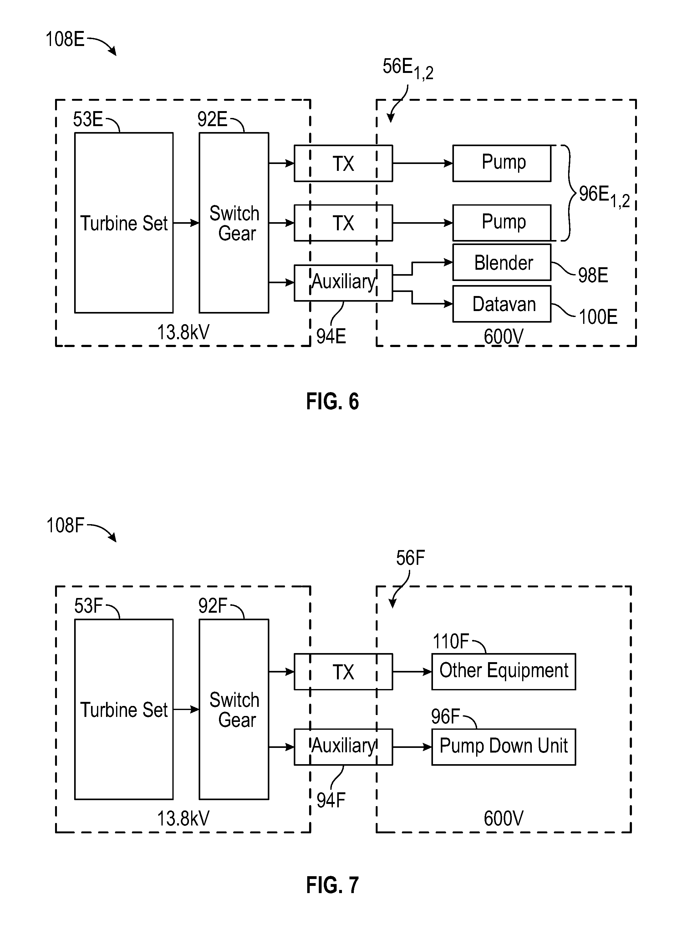
FIGS. 6 and 7 are plan schematic views of alternate examples of an electrically powered pump down system.
FIG. 8 is a perspective view of an example of an auxiliary unit for use with the system of FIGS. 1A, 1B, and 5.
While the invention will be described in connection with the preferred embodiments, it will be understood that it is not intended to limit the invention to that embodiment. On the contrary, it is intended to cover all alternatives, modifications, and equivalents, as may be included within the spirit and scope of the invention as defined by the appended claims.
DETAILED DESCRIPTION OF INVENTION
The method and system of the present disclosure will now be described more fully hereinafter with reference to the accompanying drawings in which embodiments are shown. The method and system of the present disclosure may be in many different forms and should not be construed as limited to the illustrated embodiments set forth herein; rather, these embodiments are provided so that this disclosure will be thorough and complete, and will fully convey its scope to those skilled in the art. Like numbers refer to like elements throughout. In an embodiment, usage of the term "about" includes +/-5% of the cited magnitude. In an embodiment, usage of the term "substantially" includes +/-5% of the cited magnitude.
It is to be further understood that the scope of the present disclosure is not limited to the exact details of construction, operation, exact materials, or embodiments shown and described, as modifications and equivalents will be apparent to one skilled in the art. In the drawings and specification, there have been disclosed illustrative embodiments and, although specific terms are employed, they are used in a generic and descriptive sense only and not for the purpose of limitation.
FIG. 1A is a schematic example of a system 10 that is used for providing pressurized fluid to wellbores 12.sub.1, 12.sub.2 shown intersecting a subterranean formation 16. As will be described in more detail below, the pressurized fluid can be used in fracturing and/or pump down operations in the wellbores 12.sub.1, 12.sub.2. Included with the system 10 is a hydration unit 18 that receives fluid from a fluid source 20 via line 22, and also selectively receives additives from an additive source 24 via line 26. Additive source 24 can be separate from the hydration unit 18 as a stand-alone unit, or can be included as part of the same unit as the hydration unit 18. The fluid, which in one example is water, is mixed inside of the hydration unit 18 with the additives. In an embodiment, the fluid and additives are mixed over a period of time to allow for uniform distribution of the additives within the fluid. In the example of FIG. 1A, the fluid and additive mixture is transferred to a blender unit 28 via line 30. A proppant source 32 contains proppant, which is delivered to the blender unit 28 as represented by line 34, where line 34 can be a conveyer. Inside the blender unit 28, the proppant and fluid/additive mixture are combined to form a slurry, which is then transferred to a pump assembly 36 via line 38; thus fluid in line 38 includes the discharge of blender unit 28, which is the suction (or boost) for the pump assembly 36. Blender unit 28 can have an onboard chemical additive system, such as with chemical pumps and augers. Optionally, additive source 24 can provide chemicals to blender unit 28; or a separate and standalone chemical additive system (not shown) can be provided for delivering chemicals to the blender unit 28. In an example, the pressure of the slurry in line 38 ranges from around 80 psi to around 100 psi. The pressure of the slurry can be increased up to around 15,000 psi by pump assembly 36. A motor 39, which connects to pump assembly 36 via connection 40, drives pump assembly 36 so that it can pressurize the slurry.
After being discharged from pump assembly 36, slurry is injected into a wellhead assembly 41.sub.1, 41.sub.2; discharge piping 42.sub.1, 42.sub.2 connects discharge of pump assembly 36 with wellhead assembly 41.sub.1, 41.sub.2 and provides a conduit for the slurry between the pump assembly 36 and the wellhead assembly 41.sub.1, 41.sub.2. In an alternative, hoses or other connections can be used to provide a conduit for the slurry between the pump assembly 36 and the wellhead assembly 41.sub.1, 41.sub.2. Optionally, any type of fluid can be pressurized by the pump assembly 36 to form injection fluid that is then pumped into the wellbores 12.sub.1, 12.sub.2, and is not limited to fluids having chemicals or proppant. As detailed below, fluid from pump assembly 36 can be used for fracturing the formation 16, for pump down operations in wellbores 12.sub.1, 12.sub.2. Examples exist wherein the system 10 includes multiple pump assemblies 36, and multiple motors 39 for driving the multiple fracturing pump assemblies 36. Valves 43.sub.1, 43.sub.2, are shown provided respectively on lines 42.sub.1, 42.sub.2 for selectively allowing flow into the wellhead assemblies 41.sub.1, 41.sub.2.
An example of a turbine 44 is provided in the example of FIG. 1A and which receives a combustible fuel from a fuel source 46 via a feed line 48. In one example, the combustible fuel is natural gas, and the fuel source 46 can be a container of natural gas, a pipeline, or a well (not shown) proximate the turbine 44. Combustion of the fuel in the turbine 44 in turn powers a generator 50 that produces electricity. Shaft 52 connects generator 50 to turbine 44. The combination of the turbine 44, generator 50, and shaft 52 define a turbine generator 53. In another example, gearing can also be used to connect the turbine 44 and generator 50.
An example of a micro-grid 54 is further illustrated in FIG. 1A, which distributes electricity generated by the turbine generator 53. Included with the micro-grid 54 is a transformer 56 for stepping down voltage of the electricity generated by the generator 50 to a voltage more compatible for use by electrical powered devices in the system 10. In another example, the power generated by the turbine generator and the power utilized by the electrical powered devices in the system 10 are of the same voltage, such as 4160 V so that main power transformers are not needed. In one embodiment, multiple 3500 kVA dry cast coil transformers are utilized. Electricity generated in generator 50 is conveyed to transformer 56 via line 58. In one example, transformer 56 steps the voltage down from 13.8 kV to around 600 V. Other stepped down voltages can include 4,160 V, 480 V, or other voltages. The output or low voltage side of the transformer 56 connects to a power bus 60, lines 62, 64, 66, 68, 70, and 71 connect to power bus 60 and deliver electricity to electrically powered end users in the system 10. More specifically, line 62 connects fluid source 20 to bus 60, line 64 connects additive source 24 to bus 60, line 66 connects hydration unit 18 to bus 60, line 68 connects proppant source 32 to bus 60, line 70 connects blender unit 28 to bus 60, and line 71 connects bus 60 to a variable frequency drive ("VFD") 72. Line 73 connects VFD 72 to motor 39. In one example, VFD 72 selectively provides electrical power to motor 39 via line 73, and can be used to control operation of motor 39, and thus also operation of pump 36.
In an example, additive source 24 contains ten or more chemical pumps for supplementing the existing chemical pumps on the hydration unit 18 and blender unit 28. Chemicals from the additive source 24 can be delivered via lines 26 to either the hydration unit 18 and/or the blender unit 28. In one embodiment, the elements of the system 10 are mobile and can be readily transported to a wellsite adjacent the wellbore 12, such as on trailers or other platforms equipped with wheels or tracks.
Still referring to FIG. 1A, a pump down operation is shown being performed in wellbore 12.sub.1 and wherein a perforating string 80.sub.1 is being pumped down within wellbore 12.sub.1 by pressurized fluid from the pump system 36. Thus in this example, fluid being discharged from pump system 36 is handled within discharge piping 42.sub.1 and into wellhead assembly 41.sub.1 where it is used to urge the perforating string 80.sub.1 deeper into wellbore 12.sub.1. The example of the perforating string 80.sub.1 includes perforating guns 82.sub.1 stacked in series and coaxial with one another. Each of the perforating guns 82.sub.1 include a number of shaped charges 84.sub.1 that when detonated create perforations (not shown) within formation 16. In addition, the perforating guns typically may include plugs, to isolate the guns from certain portions of the well, such as portions down hole from the guns. As will be described below, the perforations provide a starting point for fractures to be formed within formation 16 by introduction of high pressure fluid within wellbore 12.sub.1. Each of wellbores 12.sub.1, 12.sub.2 are shown having vertical, deviated and horizontal sections; however, wellbores 12.sub.1, 12.sub.2 can each be substantially vertical, or one can be vertical and the other have deviated and horizontal portions. Further illustrated in FIG. 1A is a wireline 86.sub.1 which depends downward from the wellhead assembly 41.sub.1 and to perforating string 80.sub.1. Wireline 86.sub.1 can be used to deploy and retrieve perforating string 80.sub.1 from within wellbore 12.sub.1. Moreover, signals for initiating detonation of the shaped charges 84.sub.1 can come via wireline 86.sub.1 and from surface.
FIG. 1B illustrates an example where pressurized fluid from pump system 36 has been introduced into wellbore 12.sub.1 and so that perforations 90 are formed in formation 16 and that project radially outward from wellbore 12.sub.1. As indicated above, the perforations 90 created by shaped charges 84.sub.1 (FIG. 1A) provide initiation points within formation 16 from which fluid can propagate into formation 16 to form fractures.
An advantage of the system 10 is that in situations when wellbores 12.sub.1, 12.sub.2 are proximate one another, the pump system 36 can provide pressurized fluid to each of these wellbores 12.sub.1, 12.sub.2, and for different purposes. As illustrated in FIG. 1B, the step of hydraulic fracturing is taking place in wellbore 12.sub.1, while substantially simultaneously a pump down operation is occurring in wellbore 12.sub.2. More specifically, a perforating string 80.sub.2, similar in construction to the perforating string 80.sub.1 of FIG. 1A, is being deployed within wellbore 12.sub.2. Also, perforating string 80.sub.2 includes coaxially coupled perforating guns 82.sub.2 and which each include a number of shaped charges 84.sub.2 for creating perforations (not shown) within formation 16. Deployment, retrieval, and signal communication between surface and perforating string 80.sub.2 can be accomplished via wireline 86.sub.2 shown inserted within wellbore 12.sub.2.
In one example of operation, the system 10 can be used to selectively provide the pressurized fluid to the adjacent wellbores 12.sub.1, 12.sub.2 so that what is referred to in the industry as a zipper operation can take place. A zipper operation is where adjacent wellbores are perforated and fractured along an alternating sequence. Moreover, the zipper operation is done sequentially so that the different operations can be performed on different wells on the same well site, which speeds up completion activities. As illustrated in the figures described below, separate pumping systems can provide the fluid for the fracturing and the pump down operations.
Shown in FIG. 2 is a schematic plan view of one example of system 10A where turbine generators 53A.sub.1,2 and 53A.sub.3,4 respectively generate electricity that is delivered to switch gear 92A.sub.1 and 92A.sub.2, that in turn deliver the output electricity to transformers 56A.sub.1-n and auxiliary units 94A.sub.1,2. Auxiliary unit 94A.sub.1 transmits electricity to sand equipment 32A, hydration unit 18A, frac blender 28A, and a frac data van 95A. In one example, frac data van 95A is an enclosed vehicle that provides controls and monitoring equipment for use in controlling and monitoring the fracturing system. Electricity from transformers 56A.sub.1-n, which is received from switch gear 92A.sub.1,2 is delivered at a designated voltage to fracturing pumps 36A.sub.1-n, wherein fracturing pumps 36A.sub.1-n are dedicated to pressurizing fluid for use in fracturing operations. Also from transformers 56A.sub.1-n electricity is transmitted to pump down units 96A.sub.1-n that are used for pressurizing fluid used in pump down operations as described above. It should be pointed out, that the pump down operations are not limited to disposing perforating strings within wellbores, but can include any other type of equipment that is to be positioned at a designated depth within a wellbore.
Further illustrated in FIG. 2 is that auxiliary 94A.sub.2 has an output that delivers electricity to a blender 98A for use in pump down and a data van 100A that is also used for pump down. The separate data van 100A and blender 98A can be used, for example, during zipper fracturing operations, but are not required for stack fracturing operations. This is because during stack fracturing operations, only one operation is occurring at a time, so the frac datavan 95A and frac blender 28A can be used for all operations. Further illustrated in FIG. 2 is that the power from auxiliary 94A.sub.2 transmits to an optional transformer 102A, which can be used to step down electricity for use by a crane 104A and wireline system 106A if the crane 104A and wireline system 106A require a lower voltage than the fracturing equipment. Examples exist where crane 104A and wireline system 106A provide the hoisting and signal capabilities for the wireline 86.sub.1,2 of FIGS. 1A and 1B. Moreover, wireline system 106A can include a wireline truck having a spool of wireline as well as controllers and initiation hardware for sending communication and initiation signals down the wireline 86.sub.1,2.
FIG. 3 shows, in a schematic plan view, one example of a pump down system 108B that pressurizes fluid for use in a pump down operation. In this example, a turbine set 53B is used for generating electricity, and that like the other turbine sets described herein is powered by combustion of natural gas that then drives a generator to produce electricity. The electricity is delivered to switch gear 92B and which has an output shown in communication with transformers 56B.sub.1-N and auxiliary 94B. One of transformers 56B.sub.1-N delivers electricity to other equipment 110B which can include, for example, glycol heaters, light plants, a company man trailer, water transfer pumps, a crane, wellsite tools, etc. Others of the transformers 56B.sub.1-n have outputs at designated voltages (e.g., 600V, 480V, or step up transformers) that communicate with pump down pumps 96B.sub.1-n that are schematically illustrated provided on trailers and within the pump down system 108B. Further included with the pump down system 108B is a blender 98B for blending the fluid that is then to be pressurized by the pump down pumps, and a data van 100B which provides a location for personnel to control and monitor equipment within the pump down system 108B. In this example, electricity is generated specifically for the pump down pumps and is not diverted from that being used to drive pumps used for fracturing. Additionally, the fluid being pressurized is from the pump down pumps and not from a fracturing pump.
Provided in a perspective view in FIG. 4 is one example of a pump system 36C, which can be used either for pump down operations or for fracturing operations. In the illustrated example, pumps 112C.sub.1,2 are shown mounted on a trailer 114C so that the pumps 112C.sub.1,2 can be readily transported to different locations for onsite operation. Additionally, a VFD housing 116C is also mounted on trailer 114C and in which equipment such as VFDs for pumps, isolation breakers, and a motor control center can be situated during operation of pumps 112C.sub.1,2. The motor control cabinet can be a breaker cabinet that contains breakers for smaller motors such as blower motors, lube motors, and fan motors.
Shown in FIG. 5 is an example of a blender unit 28D shown in a perspective view. Here, blender unit 28D is shown including a hopper 118D and auger assembly 119D, and wherein the hopper 118D receives sand or other proppant from a sand source, such as a conveyor (shown in FIG. 1). Auger assembly 119D, which is an elongated section having barrel and auger screws rotatably disposed within, urge the sand upward. Hopper 118D and auger assembly 119D are mounted on a trailer 120D and adjacent a mixing tub 122D, which is typically an open top tub where sand, water, and chemicals are mixed together to form a slurry that is then provided to pumps where the fluid is pressurized. The slurry that flows to pumps is directed through a manifold 124D that mounts on a lower end of trailer 120D. Also included with the blender unit 28D is a control room 126D which communicates with the datavan, houses operations personnel, and provides monitoring and controls devices for operating and monitoring of the blender unit 28D.
An alternate embodiment of a pump down system 108E is shown in a plan schematic view in FIG. 6, where turbine set 53E with a gas powered turbine generator generates electricity that is then delivered to a switch gear 92E. Output from switch gear 92E is delivered to transformers 56E.sub.1,2 that in turn provide electrical power to pump down pumps 96E.sub.1-2 shown mounted on trailers. Electricity from switch gear 92E is also directed to an auxiliary unit 94E that supplies electricity to both a blender 98E and data van 100E. Included within blender 98E is a pump (not shown) that in some embodiments pressurizes fluid to a boost pressure that is then delivered to the pump down pumps 96E.sub.1-2. In an example, the blender 98E pressurizes the fluid in a range from about 70 psi to about 120 psi. Further, within electric blender 98E chemical additives can be added to the fluid that is then delivered to the pump down pumps. Other examples exist, wherein blender for use with a pump down system is a blender that is part of the fracturing system.
Another alternate example of the pump down system 108F is illustrated in plan schematic view in FIG. 7 and where turbine set 53F, which uses gas-powered turbines to generate electricity, delivers electricity to switch gear 92F. In this example, a transformer 56F receives electricity from switch gear 92F and delivers it to other equipment 110F. Also fed by switch gear 92F is auxiliary 94F, which in turn provides electrical power to pump down unit 96F that is independent of electrical power for the hydraulic fracturing pumps. In the embodiment of FIG. 7, the pump down unit 96F can include a small boost pump (capable of, for example, up to about 20 barrels per minute (bpm) at 100 psi instead of about 130 bpm for a blender), and a water pump (capable of about 20 bpm at 10,000 psi) to replace the hydraulic fracturing pumps. Thus, the pump down system 108F of FIG. 7 is capable of operating separately from the rest of the fracking system, or from the hydraulic fracturing pumps. This flexibility allows use of the electric powered pump down system with any type of hydraulic fracturing system, whether such system is powered by electricity, diesel, or otherwise. This is also true of the embodiments shown in FIGS. 3 and 6.
FIG. 8 shows in a side perspective view an example of an auxiliary unit 94G and which includes a trailer 128G and on which a transformer 130G and a VFD house 132G are mounted. The VFD house 132G and transformer 130G can be used to power and control the desired equipment, such as, for example, the blender, the hydration unit, the conveyor, and/or the datavan. The VFD house 132G can also contain soft starters for, large non speed controlled motors, smaller blower motors and radiator fans for cooling. Power can be provided from turbines, to a switchgear, then to the auxiliary unit 94G. The transformer 130G can be used, for example, to convert power from 13.8 kV to 600V to provide power to the VFD house. The blender did not have room to contain its own VFD therefore the Auxiliary Trailer was created to serve this purpose. Each hydraulic fracturing site can benefit from the use of a single auxiliary unit 94G or multiple auxiliary units 94G depending on the individual needs and circumstances at the site.
Use of auxiliary units 94G is advantageous because each separate auxiliary unit 94G provides a separate power grid, thereby creating multiple power centers, which in turn allows for greater flexibility in the positioning of equipment at a site, and creates redundancy in the operations. The use of auxiliary units 94G also helps with power cable management, providing multiple different cable routing for the equipment.
The present invention described herein, therefore, is well adapted to carry out the objects and attain the ends and advantages mentioned, as well as others inherent therein. While a presently preferred embodiment of the invention has been given for purposes of disclosure, numerous changes exist in the details of procedures for accomplishing the desired results. These and other similar modifications will readily suggest themselves to those skilled in the art, and are intended to be encompassed within the spirit of the present invention disclosed herein and the scope of the appended claims.
* * * * *
D00000
D00001
D00002
D00003
D00004
D00005
D00006
D00007
D00008
XML
uspto.report is an independent third-party trademark research tool that is not affiliated, endorsed, or sponsored by the United States Patent and Trademark Office (USPTO) or any other governmental organization. The information provided by uspto.report is based on publicly available data at the time of writing and is intended for informational purposes only.
While we strive to provide accurate and up-to-date information, we do not guarantee the accuracy, completeness, reliability, or suitability of the information displayed on this site. The use of this site is at your own risk. Any reliance you place on such information is therefore strictly at your own risk.
All official trademark data, including owner information, should be verified by visiting the official USPTO website at www.uspto.gov. This site is not intended to replace professional legal advice and should not be used as a substitute for consulting with a legal professional who is knowledgeable about trademark law.