Cleaning device for medical instrument and method of use
Garvey , et al. Sept
U.S. patent number 10,406,316 [Application Number 15/356,982] was granted by the patent office on 2019-09-10 for cleaning device for medical instrument and method of use. This patent grant is currently assigned to Covidien LP. The grantee listed for this patent is Covidien LP. Invention is credited to Zachary Thomas Garvey, John Robert Moberg, Lance Nevala, Lucas Schneider.


View All Diagrams
| United States Patent | 10,406,316 |
| Garvey , et al. | September 10, 2019 |
Cleaning device for medical instrument and method of use
Abstract
A cleaning device for a medical instrument including a flushing chamber, the flushing chamber having a lumen sized and configured to accept a distal end portion of the medical instrument during a cleaning process. The flushing chamber has an inlet port and an outlet port. Proximal and distal sealing members of the flushing chamber seal about the medical instrument when the instrument is inserted into the lumen of the flushing chamber.
| Inventors: | Garvey; Zachary Thomas (Stillwater, MN), Moberg; John Robert (Elk River, MN), Nevala; Lance (Minneapolis, MN), Schneider; Lucas (Champlin, MN) | ||||||||||
|---|---|---|---|---|---|---|---|---|---|---|---|
| Applicant: |
|
||||||||||
| Assignee: | Covidien LP (Mansfield,
MA) |
||||||||||
| Family ID: | 50929519 | ||||||||||
| Appl. No.: | 15/356,982 | ||||||||||
| Filed: | November 21, 2016 |
Prior Publication Data
| Document Identifier | Publication Date | |
|---|---|---|
| US 20170065368 A1 | Mar 9, 2017 | |
Related U.S. Patent Documents
| Application Number | Filing Date | Patent Number | Issue Date | ||
|---|---|---|---|---|---|
| 14026001 | Sep 13, 2013 | 9532844 | |||
| 61700636 | Sep 13, 2012 | ||||
| Current U.S. Class: | 1/1 |
| Current CPC Class: | B08B 3/14 (20130101); B08B 9/0321 (20130101); B08B 9/0328 (20130101); B08B 9/023 (20130101); A61B 90/70 (20160201); A61M 25/00 (20130101); A61B 17/320783 (20130101); A61B 2090/701 (20160201); B08B 2209/032 (20130101); A61M 2025/0019 (20130101) |
| Current International Class: | A61B 90/70 (20160101); A61M 25/00 (20060101); B08B 3/14 (20060101); B08B 9/023 (20060101); B08B 9/032 (20060101); A61B 17/3207 (20060101) |
References Cited [Referenced By]
U.S. Patent Documents
| 1481078 | January 1924 | Albertson |
| 2178790 | November 1939 | Henry |
| 2701559 | February 1955 | Cooper |
| 2850007 | September 1958 | Lingley |
| 3064651 | November 1962 | Henderson |
| 3082805 | March 1963 | Royce |
| 3320957 | May 1967 | Sokolik |
| 3614953 | October 1971 | Moss |
| 3683891 | August 1972 | Eskridge et al. |
| 3705577 | December 1972 | Sierra |
| 3732858 | May 1973 | Banko |
| 3749085 | July 1973 | Willson et al. |
| 3800783 | April 1974 | Jamshidi |
| 3815604 | June 1974 | O'Malley et al. |
| 3831585 | August 1974 | Brondy et al. |
| 3837345 | September 1974 | Matar |
| 3845375 | October 1974 | Stiebel |
| 3937222 | February 1976 | Banko |
| 3945375 | March 1976 | Banko |
| 3976077 | August 1976 | Kerfoot, Jr. |
| 3995619 | December 1976 | Glatzer |
| 4007732 | February 1977 | Kvavle et al. |
| 4020847 | May 1977 | Clark, III |
| 4030503 | June 1977 | Clark, III |
| 4034744 | July 1977 | Goldberg |
| 4038985 | August 1977 | Chiulli |
| 4112708 | September 1978 | Fukuda |
| 4177797 | December 1979 | Baylis et al. |
| 4210146 | July 1980 | Banko |
| 4273128 | June 1981 | Lary |
| 4306562 | December 1981 | Osborne |
| 4306570 | December 1981 | Matthews |
| 4349032 | September 1982 | Koyata |
| 4368730 | January 1983 | Sharrock |
| 4424045 | January 1984 | Kulischenko et al. |
| 4436091 | March 1984 | Banko |
| 4445509 | May 1984 | Auth |
| 4490139 | December 1984 | Huizenga et al. |
| 4494057 | January 1985 | Hotta |
| 4512344 | April 1985 | Barber |
| 4589412 | May 1986 | Kensey |
| 4603694 | August 1986 | Wheeler |
| 4620547 | November 1986 | Boebel |
| 4631052 | December 1986 | Kensey |
| 4646719 | March 1987 | Neuman et al. |
| 4646736 | March 1987 | Auth |
| 4646738 | March 1987 | Trott |
| 4649919 | March 1987 | Thimsen et al. |
| 4653496 | March 1987 | Bundy et al. |
| 4664112 | May 1987 | Kensey et al. |
| 4669469 | June 1987 | Gifford, III et al. |
| 4679558 | July 1987 | Kensey et al. |
| 4686982 | August 1987 | Nash |
| 4692141 | September 1987 | Mahurkar |
| 4696298 | September 1987 | Higgins et al. |
| 4696667 | September 1987 | Masch |
| 4705038 | November 1987 | Sjostrom et al. |
| 4706671 | November 1987 | Weinrib |
| 4728319 | March 1988 | Masch |
| 4729763 | March 1988 | Henrie |
| 4730616 | March 1988 | Frisbie et al. |
| 4732154 | March 1988 | Shiber |
| 4733662 | March 1988 | DeSatnick et al. |
| 4745919 | May 1988 | Bundy et al. |
| 4747406 | May 1988 | Nash |
| 4747821 | May 1988 | Kensey et al. |
| 4749376 | June 1988 | Kensey et al. |
| 4754755 | July 1988 | Husted |
| 4757819 | July 1988 | Yokoi et al. |
| 4765332 | August 1988 | Fischell et al. |
| 4771774 | September 1988 | Simpson et al. |
| 4781186 | November 1988 | Simpson et al. |
| 4784636 | November 1988 | Rydell |
| 4790812 | December 1988 | Hawkins, Jr. et al. |
| 4794931 | January 1989 | Yock |
| 4817613 | April 1989 | Jaraczewski et al. |
| 4819634 | April 1989 | Shiber |
| 4819635 | April 1989 | Shapiro |
| 4838268 | June 1989 | Keith et al. |
| 4842579 | June 1989 | Shiber |
| 4844064 | July 1989 | Thimsen et al. |
| 4848343 | July 1989 | Wallsten et al. |
| 4850957 | July 1989 | Summers |
| 4857046 | August 1989 | Stevens et al. |
| 4867157 | September 1989 | McGurk-Burleson et al. |
| 4870953 | October 1989 | DonMicheal et al. |
| 4883458 | November 1989 | Shiber |
| 4886061 | December 1989 | Fischell et al. |
| 4886490 | December 1989 | Shiber |
| 4887613 | December 1989 | Farr et al. |
| 4889061 | December 1989 | McPherson et al. |
| 4894051 | January 1990 | Shiber |
| 4899757 | February 1990 | Pope, Jr. et al. |
| 4919133 | April 1990 | Chiang |
| 4923462 | May 1990 | Stevens |
| 4926858 | May 1990 | Gifford, III et al. |
| 4928693 | May 1990 | Goodin et al. |
| 4936987 | June 1990 | Persinski et al. |
| RE33258 | July 1990 | Onik et al. |
| 4950238 | August 1990 | Sullivan |
| 4954338 | September 1990 | Mattox |
| 4957482 | September 1990 | Shiber |
| 4966604 | October 1990 | Reiss |
| 4973409 | November 1990 | Cook |
| 4979939 | December 1990 | Shiber |
| 4979951 | December 1990 | Simpson |
| 4986807 | January 1991 | Farr |
| 4990134 | February 1991 | Auth |
| 4994067 | February 1991 | Summers |
| 4997435 | March 1991 | Demeter |
| 5000185 | March 1991 | Yock |
| 5002553 | March 1991 | Shiber |
| 5003918 | April 1991 | Olson et al. |
| 5007896 | April 1991 | Shiber |
| 5009659 | April 1991 | Hamlin et al. |
| 5019088 | May 1991 | Farr |
| 5024234 | June 1991 | Leary et al. |
| 5024651 | June 1991 | Shiber |
| 5026384 | June 1991 | Farr et al. |
| 5029588 | July 1991 | Yock et al. |
| 5030201 | July 1991 | Palestrant |
| 5047040 | September 1991 | Simpson et al. |
| 5049124 | September 1991 | Bales, Jr. |
| 5053044 | October 1991 | Mueller et al. |
| 5054492 | October 1991 | Scribner et al. |
| 5064435 | November 1991 | Porter |
| 5071425 | December 1991 | Gifford, III et al. |
| 5074841 | December 1991 | Ademovic et al. |
| 5077506 | December 1991 | Krause |
| 5078722 | January 1992 | Stevens |
| 5084010 | January 1992 | Plaia et al. |
| 5085662 | February 1992 | Willard |
| 5087265 | February 1992 | Summers |
| 5092839 | March 1992 | Kipperman |
| 5092873 | March 1992 | Simpson et al. |
| 5093079 | March 1992 | Bakaitis et al. |
| 5095911 | March 1992 | Pomeranz |
| 5100423 | March 1992 | Fearnot |
| 5100424 | March 1992 | Jang et al. |
| 5100426 | March 1992 | Nixon |
| 5110822 | May 1992 | Sherba et al. |
| 5112345 | May 1992 | Farr |
| 5114399 | May 1992 | Kovalcheck |
| 5115814 | May 1992 | Griffith et al. |
| 5120323 | June 1992 | Shockey et al. |
| 5127902 | July 1992 | Fischell |
| 5127917 | July 1992 | Niederhauser et al. |
| 5135531 | August 1992 | Shiber |
| 5154705 | October 1992 | Fleischhacker et al. |
| 5154724 | October 1992 | Andrews |
| 5165421 | November 1992 | Fleischhacker et al. |
| 5176693 | January 1993 | Pannek, Jr. |
| 5178625 | January 1993 | Groshong |
| 5181920 | January 1993 | Mueller et al. |
| 5183432 | February 1993 | Noguchi |
| 5190528 | March 1993 | Fonger et al. |
| 5192291 | March 1993 | Pannek, Jr. |
| 5195956 | March 1993 | Stockmeier |
| 5211651 | May 1993 | Reger et al. |
| 5217474 | June 1993 | Zacca et al. |
| 5222966 | June 1993 | Perkins et al. |
| 5224488 | July 1993 | Neuffer |
| 5224945 | July 1993 | Pannek, Jr. |
| 5224949 | July 1993 | Gomringer et al. |
| 5226909 | July 1993 | Evans et al. |
| 5226910 | July 1993 | Kajiyama et al. |
| 5234451 | August 1993 | Osypka |
| 5242460 | September 1993 | Klein et al. |
| 5242461 | September 1993 | Kortenbach et al. |
| 5250059 | October 1993 | Andreas et al. |
| 5250065 | October 1993 | Clement et al. |
| 5263928 | November 1993 | Trauthen et al. |
| 5263959 | November 1993 | Fischell |
| 5267955 | December 1993 | Hanson |
| 5267982 | December 1993 | Sylvanowicz |
| 5269793 | December 1993 | Simpson |
| 5273526 | December 1993 | Dance et al. |
| 5282484 | February 1994 | Reger |
| 5284486 | February 1994 | Kotula et al. |
| 5285795 | February 1994 | Ryan et al. |
| 5295493 | March 1994 | Radisch, Jr. |
| 5300085 | April 1994 | Yock |
| 5306294 | April 1994 | Winston et al. |
| 5308354 | May 1994 | Zacca et al. |
| 5312425 | May 1994 | Evans et al. |
| 5312427 | May 1994 | Shturman |
| 5314438 | May 1994 | Shturman |
| 5318032 | June 1994 | Lonsbury et al. |
| 5318528 | June 1994 | Heaven et al. |
| 5318576 | June 1994 | Plassche, Jr. et al. |
| 5321501 | June 1994 | Swanson et al. |
| 5322508 | June 1994 | Viera |
| 5350390 | September 1994 | Sher |
| 5356418 | October 1994 | Shturman |
| 5358472 | October 1994 | Vance et al. |
| 5358485 | October 1994 | Vance et al. |
| 5360432 | November 1994 | Shturman |
| 5366463 | November 1994 | Ryan |
| 5368035 | November 1994 | Hamm et al. |
| 5370609 | December 1994 | Drasler et al. |
| 5370651 | December 1994 | Summers |
| 5372601 | December 1994 | Lary |
| 5372602 | December 1994 | Burke |
| 5373619 | December 1994 | Fleischhacker et al. |
| 5373849 | December 1994 | Maroney et al. |
| 5377682 | January 1995 | Ueno et al. |
| 5378234 | January 1995 | Hammerslag et al. |
| 5383460 | January 1995 | Jang et al. |
| 5395311 | March 1995 | Andrews |
| 5395313 | March 1995 | Naves et al. |
| 5395335 | March 1995 | Jang |
| 5397345 | March 1995 | Lazarus |
| 5402790 | April 1995 | Jang et al. |
| 5403334 | April 1995 | Evans et al. |
| 5409454 | April 1995 | Fischell et al. |
| 5413107 | May 1995 | Oakley et al. |
| 5419774 | May 1995 | Willard et al. |
| 5423740 | June 1995 | Sullivan et al. |
| 5423799 | June 1995 | Shiu |
| 5423838 | June 1995 | Willard |
| 5423846 | June 1995 | Fischell |
| 5427107 | June 1995 | Milo et al. |
| 5429136 | July 1995 | Milo et al. |
| 5431673 | July 1995 | Summers et al. |
| 5441510 | August 1995 | Simpson et al. |
| 5443446 | August 1995 | Shturman |
| 5443497 | August 1995 | Venbrux |
| 5444078 | August 1995 | Yu et al. |
| 5445155 | August 1995 | Sieben |
| 5449369 | September 1995 | Imran |
| 5451233 | September 1995 | Yock |
| 5454809 | October 1995 | Janssen |
| 5456667 | October 1995 | Ham et al. |
| 5456689 | October 1995 | Kresch et al. |
| 5458585 | October 1995 | Salmon et al. |
| 5459570 | October 1995 | Swanson et al. |
| 5464016 | November 1995 | Nicholas et al. |
| 5470415 | November 1995 | Perkins et al. |
| 5485042 | January 1996 | Burke |
| 5485840 | January 1996 | Bauman |
| 5487729 | January 1996 | Avellanet et al. |
| 5489295 | February 1996 | Piplani et al. |
| 5491524 | February 1996 | Hellmuth et al. |
| 5496267 | March 1996 | Drasler et al. |
| 5501694 | March 1996 | Ressemann et al. |
| 5503155 | April 1996 | Salmon et al. |
| 5505210 | April 1996 | Clement |
| 5507292 | April 1996 | Jang et al. |
| 5507760 | April 1996 | Wynne et al. |
| 5507761 | April 1996 | Duer |
| 5507795 | April 1996 | Chiang et al. |
| 5511568 | April 1996 | Bowman et al. |
| 5512044 | April 1996 | Duer |
| 5514115 | May 1996 | Frantzen et al. |
| 5520189 | May 1996 | Malinowski et al. |
| 5522825 | June 1996 | Kropf et al. |
| 5522880 | June 1996 | Barone et al. |
| 5527292 | June 1996 | Adams et al. |
| 5527298 | June 1996 | Vance et al. |
| 5527325 | June 1996 | Conley et al. |
| 5531685 | July 1996 | Hemmer et al. |
| 5531690 | July 1996 | Solar |
| 5531700 | July 1996 | Moore et al. |
| 5540707 | July 1996 | Ressemann et al. |
| 5549601 | August 1996 | McIntyre et al. |
| 5554163 | September 1996 | Shturman |
| 5556408 | September 1996 | Farhat |
| 5558093 | September 1996 | Pomeranz |
| 5562726 | October 1996 | Chuter |
| 5562728 | October 1996 | Lazarus et al. |
| 5569275 | October 1996 | Kotula et al. |
| 5569276 | October 1996 | Jang et al. |
| 5569277 | October 1996 | Evans et al. |
| 5569279 | October 1996 | Rainin |
| 5570693 | November 1996 | Jang et al. |
| 5571122 | November 1996 | Kelly et al. |
| 5571130 | November 1996 | Simpson et al. |
| 5575817 | November 1996 | Martin |
| 5584842 | December 1996 | Fogarty et al. |
| 5584843 | December 1996 | Wulfman et al. |
| 5609605 | March 1997 | Marshall et al. |
| 5618293 | April 1997 | Sample et al. |
| 5620447 | April 1997 | Smith et al. |
| 5624457 | April 1997 | Farley et al. |
| 5626562 | May 1997 | Castro |
| 5626576 | May 1997 | Janssen |
| 5628761 | May 1997 | Rizik |
| 5630436 | May 1997 | Chase |
| 5632754 | May 1997 | Farley et al. |
| 5632755 | May 1997 | Nordgren et al. |
| 5634464 | June 1997 | Jang et al. |
| 5643296 | July 1997 | Hundertmark et al. |
| 5643298 | July 1997 | Nordgren et al. |
| 5649941 | July 1997 | Lary |
| 5660180 | August 1997 | Malinowski et al. |
| 5662671 | September 1997 | Barbut et al. |
| 5665098 | September 1997 | Kelly et al. |
| 5669920 | September 1997 | Conley et al. |
| 5674232 | October 1997 | Halliburton |
| 5676696 | October 1997 | Marcade |
| 5676697 | October 1997 | McDonald |
| 5681336 | October 1997 | Clement et al. |
| 5682897 | November 1997 | Pomeranz |
| 5683449 | November 1997 | Marcade |
| 5683453 | November 1997 | Palmaz |
| 5688234 | November 1997 | Frisbie |
| 5695506 | December 1997 | Pike et al. |
| 5695507 | December 1997 | Auth et al. |
| 5697944 | December 1997 | Lary |
| 5700240 | December 1997 | Barwick, Jr. et al. |
| 5700687 | December 1997 | Finn |
| 5707350 | January 1998 | Krause et al. |
| 5707376 | January 1998 | Kavteladze et al. |
| 5707383 | January 1998 | Bays et al. |
| 5709698 | January 1998 | Adams et al. |
| 5713913 | February 1998 | Lary et al. |
| 5715825 | February 1998 | Crowley |
| 5716410 | February 1998 | Wang et al. |
| 5720735 | February 1998 | Dorros |
| 5724977 | March 1998 | Yock et al. |
| 5728123 | March 1998 | Lemelson et al. |
| 5733296 | March 1998 | Rogers et al. |
| 5735816 | April 1998 | Lieber et al. |
| 5741270 | April 1998 | Hansen et al. |
| 5766192 | June 1998 | Zacca |
| 5772674 | June 1998 | Nakhjavan |
| 5775327 | July 1998 | Randolph et al. |
| 5776114 | July 1998 | Frantzen et al. |
| 5776153 | July 1998 | Rees |
| 5779643 | July 1998 | Lum et al. |
| 5779673 | July 1998 | Roth et al. |
| 5779721 | July 1998 | Nash |
| 5779722 | July 1998 | Shturman et al. |
| 5792157 | August 1998 | Mische et al. |
| 5797949 | August 1998 | Parodi |
| 5799655 | September 1998 | Jang et al. |
| 5807329 | September 1998 | Gelman |
| 5807340 | September 1998 | Pokras |
| 5810867 | September 1998 | Zarbatany et al. |
| 5816923 | October 1998 | Milo et al. |
| 5820592 | October 1998 | Hammerslag |
| 5823971 | October 1998 | Robinson et al. |
| 5824039 | October 1998 | Piplani et al. |
| 5824055 | October 1998 | Spiridigliozzi et al. |
| 5827201 | October 1998 | Samson et al. |
| 5827229 | October 1998 | Auth et al. |
| 5827304 | October 1998 | Hart |
| 5827322 | October 1998 | Williams |
| 5830224 | November 1998 | Cohn et al. |
| 5836957 | November 1998 | Schulz et al. |
| 5843022 | December 1998 | Willard et al. |
| 5843103 | December 1998 | Wulfman |
| 5843161 | December 1998 | Solovay |
| 5855563 | January 1999 | Kaplan et al. |
| 5865748 | February 1999 | Co et al. |
| 5868685 | February 1999 | Powell et al. |
| 5868767 | February 1999 | Farley et al. |
| 5871536 | February 1999 | Lazarus |
| 5873882 | February 1999 | Straub et al. |
| 5876414 | March 1999 | Straub |
| 5879397 | March 1999 | Kalberer et al. |
| 5882589 | March 1999 | Mariotti |
| 5883458 | March 1999 | Sumita et al. |
| 5888201 | March 1999 | Stinson et al. |
| 5895399 | April 1999 | Barbut et al. |
| 5895402 | April 1999 | Hundertmark et al. |
| 5902245 | May 1999 | Yock |
| 5910150 | June 1999 | Saadat |
| 5911734 | June 1999 | Tsugita et al. |
| 5916210 | June 1999 | Winston |
| 5922003 | July 1999 | Anctil et al. |
| 5935108 | August 1999 | Katoh et al. |
| 5938645 | August 1999 | Gordon |
| 5938671 | August 1999 | Katoh et al. |
| 5938672 | August 1999 | Nash |
| 5941869 | August 1999 | Patterson et al. |
| 5947985 | September 1999 | Imran |
| 5948184 | September 1999 | Frantzen et al. |
| 5951480 | September 1999 | White et al. |
| 5951482 | September 1999 | Winston et al. |
| 5954745 | September 1999 | Gertler et al. |
| 5968064 | October 1999 | Selmon et al. |
| 5972019 | October 1999 | Engelson et al. |
| 5979951 | November 1999 | Shimura |
| 5985397 | November 1999 | Witt et al. |
| 5989281 | November 1999 | Barbut et al. |
| 5997557 | December 1999 | Barbut et al. |
| 6001112 | December 1999 | Taylor |
| 6010449 | January 2000 | Selmon et al. |
| 6010522 | January 2000 | Barbut et al. |
| 6013072 | January 2000 | Winston et al. |
| 6019778 | February 2000 | Wilson et al. |
| 6022362 | February 2000 | Lee et al. |
| 6027450 | February 2000 | Brown et al. |
| 6027460 | February 2000 | Shturman |
| 6027514 | February 2000 | Stine et al. |
| 6032673 | March 2000 | Savage et al. |
| 6036646 | March 2000 | Barthe et al. |
| 6036656 | March 2000 | Slater |
| 6036707 | March 2000 | Spaulding |
| 6039693 | March 2000 | Seward et al. |
| 6016649 | April 2000 | Bock et al. |
| 6048349 | April 2000 | Winston et al. |
| 6050949 | April 2000 | White et al. |
| 6063093 | May 2000 | Winston et al. |
| 6066153 | May 2000 | Lev |
| 6068603 | May 2000 | Suzuki |
| 6068638 | May 2000 | Makower |
| 6081738 | June 2000 | Hinohara et al. |
| RE36764 | July 2000 | Zacca et al. |
| 6095990 | August 2000 | Parodi |
| 6099542 | August 2000 | Cohn et al. |
| 6106515 | August 2000 | Winston et al. |
| 6110121 | August 2000 | Lenker |
| 6120515 | September 2000 | Rogers et al. |
| 6120516 | September 2000 | Selmon et al. |
| 6126649 | October 2000 | VanTassel et al. |
| 6129734 | October 2000 | Shturman et al. |
| 6134003 | October 2000 | Tearney et al. |
| 6152909 | November 2000 | Bagaoisan et al. |
| 6152938 | November 2000 | Curry |
| 6156046 | December 2000 | Passafaro et al. |
| 6157852 | December 2000 | Selmon et al. |
| 6159195 | December 2000 | Ha et al. |
| 6159225 | December 2000 | Makower |
| 6165127 | December 2000 | Crowley |
| 6179859 | January 2001 | Bates et al. |
| 6183432 | February 2001 | Milo |
| 6187025 | February 2001 | Machek |
| 6190353 | February 2001 | Makower et al. |
| 6191862 | February 2001 | Swanson et al. |
| 6193676 | February 2001 | Winston et al. |
| 6196963 | March 2001 | Williams |
| 6206898 | March 2001 | Honeycutt et al. |
| 6217527 | April 2001 | Selmon et al. |
| 6217549 | April 2001 | Selmon et al. |
| 6217595 | April 2001 | Shturman et al. |
| 6221049 | April 2001 | Selmon et al. |
| 6221332 | April 2001 | Thumm et al. |
| 6228049 | May 2001 | Schroeder et al. |
| 6228076 | May 2001 | Winston et al. |
| 6231546 | May 2001 | Milo et al. |
| 6231549 | May 2001 | Noecker et al. |
| 6235000 | May 2001 | Milo et al. |
| 6238405 | May 2001 | Findlay, III et al. |
| 6241667 | June 2001 | Vetter et al. |
| 6241744 | June 2001 | Imran et al. |
| 6245012 | June 2001 | Kleshinski |
| 6258052 | July 2001 | Milo |
| 6263236 | July 2001 | Kasinkas et al. |
| 6264611 | July 2001 | Ishikawa et al. |
| 6266550 | July 2001 | Selmon et al. |
| 6277138 | August 2001 | Levinson et al. |
| 6283951 | September 2001 | Flaherty et al. |
| 6283983 | September 2001 | Makower et al. |
| 6299622 | October 2001 | Snow et al. |
| 6299623 | October 2001 | Wulfman |
| 6302875 | October 2001 | Makower et al. |
| 6305834 | October 2001 | Schubert et al. |
| 6312444 | November 2001 | Barbut |
| 6319242 | November 2001 | Patterson et al. |
| 6319275 | November 2001 | Lashinski et al. |
| 6330884 | December 2001 | Kim |
| 6355005 | March 2002 | Powell et al. |
| 6361545 | March 2002 | Macoviak et al. |
| 6375615 | April 2002 | Flaherty et al. |
| 6383195 | May 2002 | Richard |
| 6383205 | May 2002 | Samson et al. |
| 6394976 | May 2002 | Winston et al. |
| 6398798 | June 2002 | Selmon et al. |
| 6422736 | July 2002 | Antoniades et al. |
| 6423081 | July 2002 | Lee et al. |
| 6425870 | July 2002 | Flesch |
| 6428551 | August 2002 | Hall et al. |
| 6428552 | August 2002 | Sparks |
| 6443966 | September 2002 | Shiu |
| 6445939 | September 2002 | Swanson et al. |
| 6447525 | September 2002 | Follmer et al. |
| 6451036 | September 2002 | Heitzmann et al. |
| 6454779 | September 2002 | Taylor |
| 6475226 | November 2002 | Belef et al. |
| 6482217 | November 2002 | Pintor et al. |
| 6497711 | December 2002 | Plaia et al. |
| 6501551 | December 2002 | Tearney et al. |
| 6520975 | February 2003 | Branco |
| RE38018 | March 2003 | Anctil et al. |
| 6532380 | March 2003 | Close et al. |
| 6533749 | March 2003 | Mitusina et al. |
| 6561998 | May 2003 | Roth et al. |
| 6565588 | May 2003 | Clement et al. |
| 6569177 | May 2003 | Dillard et al. |
| 6592526 | July 2003 | Lenker |
| 6620180 | September 2003 | Bays et al. |
| 6623437 | September 2003 | Hinchliffe et al. |
| 6623495 | September 2003 | Findlay, III et al. |
| 6623496 | September 2003 | Snow et al. |
| 6629953 | October 2003 | Boyd |
| 6638233 | October 2003 | Corvi et al. |
| RE38335 | November 2003 | Aust et al. |
| 6652505 | November 2003 | Tsugita |
| 6652548 | November 2003 | Evans et al. |
| 6656195 | December 2003 | Peters et al. |
| 6666874 | December 2003 | Heitzmann et al. |
| 6682543 | January 2004 | Barbut et al. |
| 6733511 | May 2004 | Hall et al. |
| 6740103 | May 2004 | Hall et al. |
| 6746462 | June 2004 | Selmon et al. |
| 6764495 | July 2004 | Lee et al. |
| 6790204 | September 2004 | Zadno-Azizi et al. |
| 6790215 | September 2004 | Findlay, III et al. |
| 6818001 | November 2004 | Wulfman et al. |
| 6830577 | December 2004 | Nash et al. |
| 6843797 | January 2005 | Nash et al. |
| 6849068 | February 2005 | Bagaoisan et al. |
| 6863676 | March 2005 | Lee et al. |
| 6911026 | June 2005 | Hall et al. |
| 6970732 | November 2005 | Winston et al. |
| 6997934 | February 2006 | Snow et al. |
| 7153315 | December 2006 | Miller |
| 7172610 | February 2007 | Heitzmann et al. |
| 7208511 | April 2007 | Williams et al. |
| 7235088 | June 2007 | Pintor et al. |
| 7318831 | January 2008 | Alvarez et al. |
| 7388495 | June 2008 | Fallin et al. |
| 7479148 | January 2009 | Beaupre |
| 7488322 | February 2009 | Brunnett et al. |
| 7524289 | April 2009 | Lenker |
| 7603166 | October 2009 | Casscells, III et al. |
| 7708749 | May 2010 | Simpson et al. |
| 7713235 | May 2010 | Torrance et al. |
| 7713279 | May 2010 | Simpson et al. |
| 7729745 | June 2010 | Maschke |
| 7734332 | June 2010 | Sher |
| 7753852 | July 2010 | Maschke |
| 7758599 | July 2010 | Snow et al. |
| 7771444 | August 2010 | Patel et al. |
| 7887556 | February 2011 | Simpson et al. |
| 8226674 | July 2012 | Simpson et al. |
| 2001/0000041 | March 2001 | Selmon et al. |
| 2001/0031784 | October 2001 | Petersen et al. |
| 2001/0031981 | October 2001 | Evans et al. |
| 2001/0044622 | November 2001 | Vardi et al. |
| 2001/0049500 | December 2001 | VanTassel et al. |
| 2002/0019644 | February 2002 | Hastings et al. |
| 2002/0022788 | February 2002 | Corvi et al. |
| 2002/0058904 | May 2002 | Boock et al. |
| 2002/0077373 | June 2002 | Hudson et al. |
| 2002/0077642 | June 2002 | Patel et al. |
| 2002/0095141 | July 2002 | Belef et al. |
| 2002/0103459 | August 2002 | Sparks et al. |
| 2002/0177800 | November 2002 | Bagaoisan et al. |
| 2002/0188307 | December 2002 | Pintor et al. |
| 2003/0018346 | January 2003 | Follmer et al. |
| 2003/0023263 | January 2003 | Krolik et al. |
| 2003/0093098 | May 2003 | Heitzmann et al. |
| 2003/0120295 | June 2003 | Simpson et al. |
| 2003/0125757 | July 2003 | Patel et al. |
| 2003/0125758 | July 2003 | Simpson et al. |
| 2003/0163126 | August 2003 | West, Jr. |
| 2003/0199747 | October 2003 | Michlitsch et al. |
| 2003/0206484 | November 2003 | Childers et al. |
| 2003/0229369 | December 2003 | Findlay, III et al. |
| 2004/0006358 | January 2004 | Wulfman et al. |
| 2004/0049225 | March 2004 | Denison |
| 2004/0167553 | August 2004 | Simpson et al. |
| 2004/0167554 | August 2004 | Simpson et al. |
| 2004/0193034 | September 2004 | Wasicek et al. |
| 2004/0210245 | October 2004 | Erickson et al. |
| 2005/0004585 | January 2005 | Hall et al. |
| 2005/0004594 | January 2005 | Nool et al. |
| 2005/0021063 | January 2005 | Hall et al. |
| 2005/0042239 | February 2005 | Lipiecki et al. |
| 2005/0090845 | April 2005 | Boyd |
| 2005/0090849 | April 2005 | Adams |
| 2005/0177068 | August 2005 | Simpson |
| 2005/0191222 | September 2005 | Lin et al. |
| 2005/0216018 | September 2005 | Sennett |
| 2005/0222596 | October 2005 | Maschke |
| 2005/0222663 | October 2005 | Simpson et al. |
| 2006/0015126 | January 2006 | Sher |
| 2006/0235334 | October 2006 | Corvi et al. |
| 2006/0259052 | November 2006 | Pintor et al. |
| 2007/0010840 | January 2007 | Rosenthal et al. |
| 2007/0038061 | February 2007 | Huennekens et al. |
| 2007/0049958 | March 2007 | Adams |
| 2007/0135712 | June 2007 | Maschke |
| 2007/0135886 | June 2007 | Maschke |
| 2007/0167824 | July 2007 | Lee et al. |
| 2007/0225739 | September 2007 | Pintor et al. |
| 2007/0265647 | November 2007 | Bonnette et al. |
| 2007/0276419 | November 2007 | Rosenthal |
| 2008/0001643 | January 2008 | Lee |
| 2008/0004644 | January 2008 | To et al. |
| 2008/0004645 | January 2008 | To et al. |
| 2008/0004646 | January 2008 | To et al. |
| 2008/0004647 | January 2008 | To et al. |
| 2008/0045986 | February 2008 | To et al. |
| 2008/0051735 | February 2008 | Measamer |
| 2008/0051812 | February 2008 | Schmitz et al. |
| 2008/0065124 | March 2008 | Olson |
| 2008/0065125 | March 2008 | Olson |
| 2008/0097403 | April 2008 | Donaldson et al. |
| 2008/0125799 | May 2008 | Adams |
| 2008/0161840 | July 2008 | Osiroff et al. |
| 2008/0177139 | July 2008 | Courtney et al. |
| 2008/0208227 | August 2008 | Kadykowski et al. |
| 2008/0249553 | October 2008 | Gruber et al. |
| 2008/0312673 | December 2008 | Viswanathan et al. |
| 2009/0012548 | January 2009 | Thatcher et al. |
| 2009/0018565 | January 2009 | To et al. |
| 2009/0018566 | January 2009 | Escudero et al. |
| 2009/0138031 | May 2009 | Tsukernik |
| 2009/0187203 | July 2009 | Corvi et al. |
| 2009/0216125 | August 2009 | Lenker |
| 2009/0216180 | August 2009 | Lee et al. |
| 2009/0226063 | September 2009 | Rangwala et al. |
| 2009/0234378 | September 2009 | Escudero et al. |
| 2009/0270888 | October 2009 | Patel et al. |
| 2009/0275966 | November 2009 | Mitusina |
| 2009/0299394 | December 2009 | Simpson et al. |
| 2009/0306689 | December 2009 | Welty et al. |
| 2010/0030216 | February 2010 | Arcenio |
| 2010/0049225 | February 2010 | To et al. |
| 2010/0130996 | May 2010 | Doud et al. |
| 2010/0198240 | August 2010 | Simpson et al. |
| 2010/0241147 | September 2010 | Maschke |
| 2010/0280534 | November 2010 | Sher |
| 2010/0292721 | November 2010 | Moberg |
| 2010/0298850 | November 2010 | Snow et al. |
| 2010/0312263 | December 2010 | Moberg et al. |
| 2011/0004107 | January 2011 | Rosenthal et al. |
| 2011/0022069 | January 2011 | Mitusina |
| 2011/0040315 | February 2011 | To et al. |
| 2011/0130777 | June 2011 | Zhang et al. |
| 2011/0144673 | June 2011 | Zhang et al. |
| 2011/0224642 | September 2011 | Fojtik |
| 2012/0330336 | December 2012 | Simpson et al. |
| 2015/0090620 | April 2015 | Seitz, III |
| 2000621 | Oct 1989 | CA | |||
| 101795630 | Aug 2010 | CN | |||
| 3732236 | Sep 1987 | DE | |||
| 8900059 | Jan 1989 | DE | |||
| 9303531.4 | Mar 1993 | DE | |||
| 4444166 | Jun 1996 | DE | |||
| 29722136 | Apr 1999 | DE | |||
| 0 086 048 | Aug 1983 | EP | |||
| 0 107 009 | May 1984 | EP | |||
| 0 229 620 | Jul 1987 | EP | |||
| 0 291 170 | Nov 1988 | EP | |||
| 0 302 701 | Feb 1989 | EP | |||
| 0 330 843 | Sep 1989 | EP | |||
| 0 373 927 | Jun 1990 | EP | |||
| 0 421 457 | Apr 1991 | EP | |||
| 0 431 752 | Jun 1991 | EP | |||
| 0 448 859 | Oct 1991 | EP | |||
| 0 463 798 | Jan 1992 | EP | |||
| 0 490 565 | Jun 1992 | EP | |||
| 0 514 810 | Nov 1992 | EP | |||
| 0 526 042 | Feb 1993 | EP | |||
| 0 533 320 | Mar 1993 | EP | |||
| 0 608 911 | Aug 1994 | EP | |||
| 0 608 912 | Aug 1994 | EP | |||
| 0 611 522 | Aug 1994 | EP | |||
| 0 648 414 | Apr 1995 | EP | |||
| 0 657 140 | Jun 1995 | EP | |||
| 0 680 695 | Nov 1995 | EP | |||
| 0 983 749 | Mar 2000 | EP | |||
| 1 767 159 | Mar 2007 | EP | |||
| 1 875 871 | Jan 2008 | EP | |||
| 2 093 353 | Sep 1982 | GB | |||
| 2 115 829 | Sep 1983 | GB | |||
| 2 210 965 | Jun 1989 | GB | |||
| 2-206452 | Aug 1990 | JP | |||
| 2-271847 | Nov 1990 | JP | |||
| 3-186256 | Aug 1991 | JP | |||
| 04-200459 | Jul 1992 | JP | |||
| 05-042162 | Feb 1993 | JP | |||
| 05-056984 | Mar 1993 | JP | |||
| 5184679 | Jul 1993 | JP | |||
| 6-269460 | Sep 1994 | JP | |||
| 7-75611 | Aug 1995 | JP | |||
| 442795 | Sep 1974 | SU | |||
| 665908 | Jun 1979 | SU | |||
| 89/06517 | Jul 1989 | WO | |||
| 9207500 | May 1992 | WO | |||
| 93/13716 | Jul 1993 | WO | |||
| 93/13717 | Jul 1993 | WO | |||
| 93/16642 | Sep 1993 | WO | |||
| 95/21576 | Aug 1995 | WO | |||
| 96/11648 | Apr 1996 | WO | |||
| 97/46164 | Dec 1997 | WO | |||
| 98/04199 | Feb 1998 | WO | |||
| 98/24372 | Jun 1998 | WO | |||
| 99/39648 | Aug 1999 | WO | |||
| 99/52454 | Oct 1999 | WO | |||
| 00/30531 | Jun 2000 | WO | |||
| 00/54735 | Sep 2000 | WO | |||
| 00/62913 | Oct 2000 | WO | |||
| 00/68300 | Nov 2000 | WO | |||
| 00/72955 | Dec 2000 | WO | |||
| 01/15609 | Mar 2001 | WO | |||
| 01/19444 | Mar 2001 | WO | |||
| 01/30433 | May 2001 | WO | |||
| 01/43809 | Jun 2001 | WO | |||
| 01/43857 | Jun 2001 | WO | |||
| 02/16017 | Feb 2002 | WO | |||
| 02/45598 | Jun 2002 | WO | |||
| 2006/058223 | Jun 2006 | WO | |||
| 2006/066012 | Jun 2006 | WO | |||
Other References
|
Amplatz Coronary Catheters, posted: Feb. 25, 2009, [online], [retrieved on Mar. 29, 2011], retrieved from the Cardiophile MD using Internet website <URL:http://cardiophile.org/2009/02/amplatzcoronary-catheter.html> (3 pages). cited by applicant . Judkins Left Coronary Catheter, posted: Feb. 19, 2009, [online], [retrieved on Mar. 29, 2011], retrieved from the Cardiophile MD using Internet website <URL:http://cardiophile.org/2009/02/judkins-left-coronary-catheter.htm- l> (3 pages). cited by applicant . Huang et al., "Optical Coherence Tomography," Science, 254: 1178-1181 (1991). cited by applicant . Brezinski et al., "Optical Coherence Tomography for Optical Biopsy," Circulation, 93: 1206-1213 (1996). cited by applicant . Brezinski et al., "Assessing Atherosclerotic Plaque Morphology: Comparison of Optical Coherence Tomography and High Frequency Intravascular Ultrasound," Heart, 77:397-403 (1997). cited by applicant. |
Primary Examiner: Perrin; Joseph L.
Assistant Examiner: Graf; Irina
Parent Case Text
CROSS-REFERENCE TO RELATED APPLICATION
The present application is a continuation application of U.S. application Ser. No. 14/026,001, filed Sep. 13, 2013, issued as U.S. Pat. No. 9,532,844, which claims the benefit of U.S. Provisional Application Ser. No. 61/700,636, filed Sep. 13, 2012, the entirety of each of which is hereby incorporated by reference.
Claims
What is claimed is:
1. A cleaning device for cleaning a medical instrument, the medical instrument having a distal end portion defining an instrument lumen and first and second openings in fluid communication with the instrument lumen, the first and second openings being spaced apart lengthwise along the distal end portion of the instrument lumen, the cleaning device comprising: a flushing chamber comprising a main wall portion that defines a flushing lumen having a length extending between opposite proximal and distal ends, extending between the proximal and distal ends, the flushing lumen the flushing chamber further comprising a lateral wall portion connected to the main wall portion, the lateral wall portion defining a port in fluid communication with the flushing lumen, the port extending transversely to the length of the flushing lumen; a proximal sealing member coupled to the main wall portion of the flushing chamber at a location proximal of the port; and a distal sealing member coupled to the main wall portion of the flushing chamber at a location distal of the port, wherein the distal sealing member comprises a duckbill valve having a tapered proximal end received in the flushing lumen of the flushing chamber; and wherein the flushing chamber is configured to accept the distal end portion of the medical instrument in the flushing chamber through the proximal end of the flushing chamber such that: the proximal sealing member fluidly seals about the medical instrument for inhibiting fluid flow out of the flushing lumen between the proximal sealing member and the medical instrument; the distal sealing member fluidly seals about the medical instrument for inhibiting fluid flow out of the flushing lumen between the distal sealing member and the medical instrument; the first opening is received in the flushing lumen between the proximal and distal sealing members; the second opening is one of (a) spaced apart proximally of the proximal opening and (b) spaced apart distally of the distal opening; and fluid imparted into flushing lumen through the port is directed to flow into the first opening, through the instrument lumen, and out the second opening.
2. The cleaning device of claim 1, wherein the port comprises a proximal port and the flushing chamber further comprises a distal port in fluid communication with the flushing lumen.
3. The cleaning device of claim 2, further comprising a vacuum source coupled to the distal port of the flushing chamber.
4. The cleaning device of claim 2, wherein the distal port comprises first and second distal ports.
5. The cleaning device of claim 4, wherein the first distal port has a first stop valve having an open position and a closed position, and wherein the second distal port has a second stop valve having an open position and a closed position.
6. The cleaning device of claim 2, further comprising a tube fluidly connecting the proximal and distal ports of the flushing chamber to at least partially define a closed loop fluid circuit.
7. The cleaning device of claim 6, wherein the tube has first and second ends, the first end of the tube coupled to the proximal port of the flushing chamber and the second end of the tube coupled to the distal port of the flushing chamber.
8. The cleaning device of claim 7, further comprising: a pump in fluid communication with the tube and flushing chamber; and a filter in fluid communication with the tube and flushing chamber.
9. The cleaning device of claim 8, wherein the pump is coupled to the tube adjacent the proximal port of the flushing chamber.
10. The cleaning device of claim 8, wherein the filter is coupled to the tube adjacent the distal port of the flushing chamber.
11. The cleaning device of claim 2, further comprising a syringe having a fluid chamber for fluid and a fluid outlet port fluidly connectable to the proximal port of the flushing chamber, the syringe further having a push rod and a piston, wherein the syringe is configured to inject fluid into the proximal port of the flushing chamber, wherein the syringe has a syringe inlet port for receiving fluid into the fluid chamber.
12. The cleaning device of claim 11, further comprising a tube fluidly connecting the inlet port of the syringe and the distal port of the flushing chamber.
13. The cleaning device of claim 11, wherein the piston of the syringe divides the fluid chamber into a pressure chamber and a vacuum chamber, the syringe inlet port being in fluid communication with the vacuum chamber.
14. The cleaning device of claim 1, wherein the proximal sealing member comprises a valve having an open position sized to allow insertion of the medical instrument into the flushing chamber, and a closed position in which the proximal sealing member fluidly seals about the medical instrument when the medical instrument is inserted into the flushing chamber.
15. The cleaning device of claim 1, further comprising: a syringe having a fluid chamber for fluid and a fluid outlet port fluidly connectable to the port of the flushing chamber, the syringe further having a push rod and a piston, wherein the syringe is configured to inject fluid into the port of the flushing chamber.
16. A medical device comprising: a medical instrument having a distal end portion defining an instrument lumen and first and second openings in fluid communication with the instrument lumen, wherein the first and second openings are spaced apart lengthwise along the distal end portion of the instrument lumen; and a cleaning device comprising: a flushing chamber comprising a main wall portion that defines a flushing lumen having a length extending between opposite proximal and distal ends, the flushing chamber further comprising a lateral wall portion connected to the main wall portion, the lateral wall portion defining a port in fluid communication with the flushing lumen, the port extending transversely to the length of the flushing lumen; a proximal sealing member coupled to the main wall portion of the flushing chamber at a location proximal of the port; and a distal sealing member coupled to the main wall portion of the flushing chamber at a location distal of the port, wherein the distal sealing member comprises a duckbill valve having a tapered proximal end received in the flushing lumen of the flushing chamber; and wherein the flushing chamber is configured to accept the distal end portion of the medical instrument in the flushing chamber through the proximal end of the flushing chamber such that: the proximal sealing member fluidly seals about the medical instrument for inhibiting fluid flow out of the flushing lumen between the proximal sealing member and the medical instrument; the distal sealing member fluidly seals about the medical instrument for inhibiting fluid flow out of the flushing lumen between the distal sealing member and the medical instrument; the first opening is received in the flushing lumen between the proximal and distal sealing members; the second opening is one of (a) spaced apart proximally of the proximal opening and (b) spaced apart distally of the distal opening; and fluid imparted into flushing lumen through the port is directed to flow into the first opening, through the instrument lumen, and out the second opening.
17. The medical device set forth in claim 16, wherein the medical instrument comprises a catheter.
Description
FIELD OF THE INVENTION
The present invention relates to a cleaning device for cleaning a medical instrument. More particularly, this invention relates to a cleaning device capable of cleaning residual matter from a distal end portion of a catheter.
BACKGROUND
Medical instruments, including those used in surgical or intravascular procedures require cleaning to remove matter such as plaque, calcium, blood, tissue, and other luminal debris in an effective, efficient and timely manner. However, some medical devices, including catheters, can be difficult to clean quickly and efficiently because of their size and construction.
SUMMARY OF THE DISCLOSURE
Various embodiments of cleaning devices and their methods of use are disclosed. Distinguishing features that may be included in these cleaning devices and methods are described below. It is intended that the cleaning devices and methods may include one or more of these features individually or in combination and it is not intended that the cleaning devices or the methods of use be limited to the specific embodiments described herein.
In one aspect, a cleaning device for a medical instrument includes a flushing chamber. The flushing chamber has a lumen sized and configured to accept a distal end portion of the medical instrument during a cleaning process. The flushing chamber has an inlet port and an outlet port. Proximal and distal sealing members of the flushing chamber seal about the medical instrument when the instrument is inserted into the lumen of the flushing chamber.
DESCRIPTION OF THE DRAWINGS
FIG. 1 is a schematic side elevational view of first embodiment of a cleaning device.
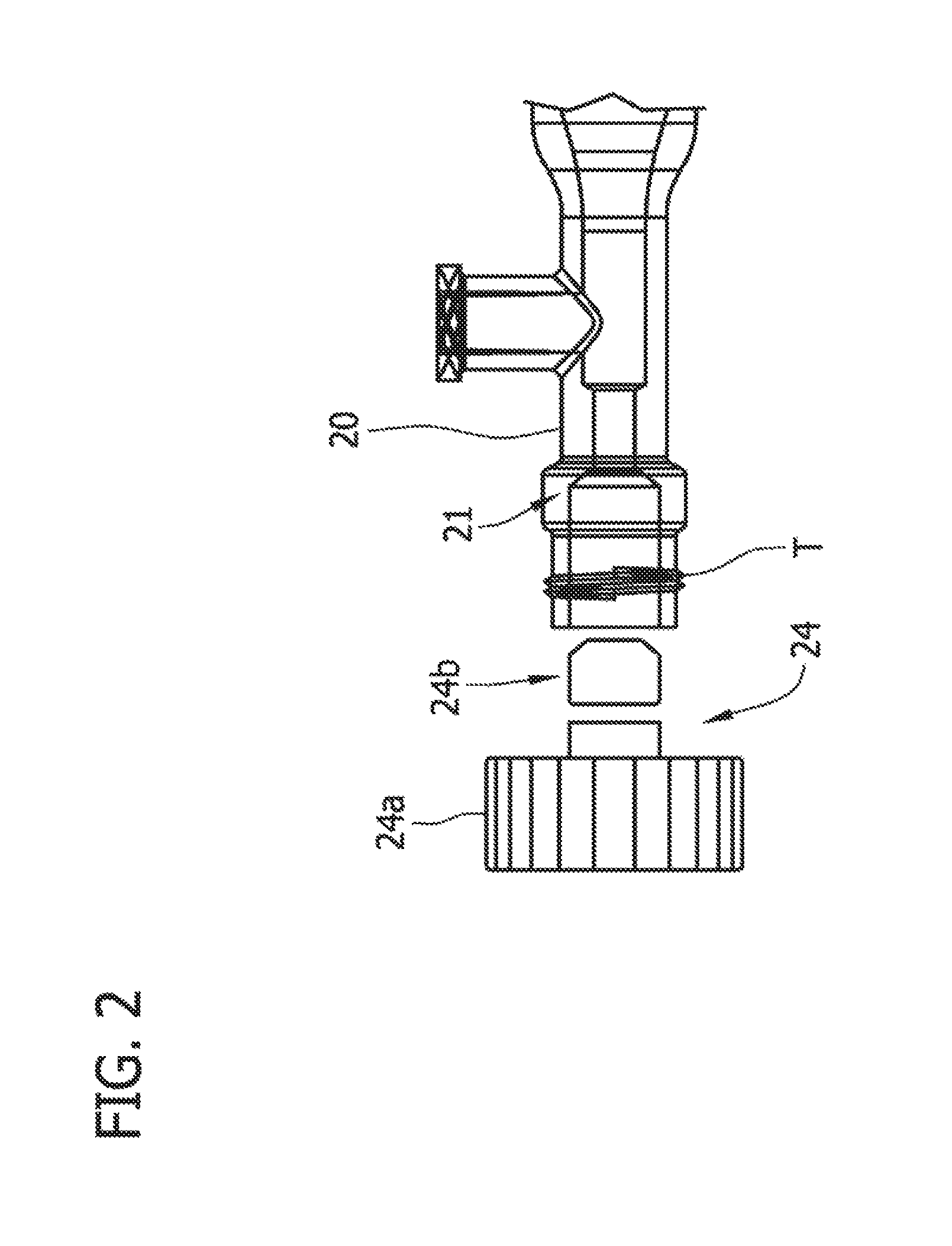
FIG. 2 is an enlarged, fragmentary side elevational view of the cleaning device, showing a valve exploded from a proximal end of a flushing chamber of the cleaning device.
FIG. 3 is an enlarged, fragmentary side elevational elevational view of the cleaning device, showing the valve secured to the proximal end of flushing chamber of the cleaning device.
FIG. 4 is a side elevational view of a second embodiment of a cleaning device.
FIG. 5 is a side elevational view of a third embodiment of the cleaning device, the cleaning device having a translucent flushing chamber;
FIG. 6 is an exploded, side elevational view of the third embodiment of the cleaning device.
FIG. 7 is an enlarged perspective of a valve of the third embodiment of the cleaning device;
FIG. 8 is an enlarged side elevational view of the valve;
FIG. 9 is a side elevational view of a medical device being cleaned according to a first method of using the first embodiment of the cleaning device.
FIG. 10 is a side elevational view of a medical device being cleaned according to a first method of using the second embodiment of the cleaning device.
FIG. 11 is an enlarged, fragmentary side elevational view of a medical device being cleaned according to a first method of using the third embodiment of the cleaning device a flushing chamber being translucent.
FIG. 12 is a side elevational view of the medical device being cleaned according to the first method of using the third embodiment of the cleaning device, the flushing chamber being translucent.
FIG. 13 is a side elevational view of a medical device being cleaned according to a second method of using the first embodiment of the cleaning device.
FIG. 14 is a side elevational view of a medical device being cleaned according to a second method of using the second embodiment of the cleaning device.
FIG. 15 is a side elevational view of a syringe of an embodiment for use with one or more embodiments of the cleaning device.
FIG. 16 is a side elevational view of a medical device being cleaned according to a third method of using the first embodiment of the cleaning device.
FIG. 17 is a side elevational view of a fourth embodiment of a cleaning device.
DESCRIPTION OF THE DISCLOSURE
Described herein are embodiments of a device and method for cleaning and flushing residual matter from a medical device including but not limited to an intraluminal surgical device including a catheter. Although the various embodiments of the cleaning device are described herein for use in cleaning catheters having catheter bodies adapted for intraluminal introduction the devices may also be used to clean other intraluminal surgical devices or other medical devices of a general nature. In other words, it is not intended that the use of the embodiments described herein be limited to cleaning intraluminal catheters. The dimensions and other physical characteristics of the cleaning device may vary significantly depending on the size and/or physical characteristics of the catheter, surgical instrument, or other medical device to be cleaned.
FIG. 1 depicts a side view of a first embodiment of the cleaning device. A cleaning device 10 is shown and comprises a body that may be elongate in shape and that includes a flushing chamber 20. Flushing chamber 20 may be translucent and may be formed from many well-known plastics. Injection moldings and similar procedures are techniques for manufacturing medical quality tools known in the art. Many materials and manufacturing methods may be utilized to form the body including the flushing chamber. Flushing chamber 20 may be any desired shape or size depending upon the application and may be molded or otherwise constructed in size and shape to house a specific catheter. Flushing chamber 20 contains a distal end 22 and a main lumen 31 that accepts and houses a distal end portion of catheter C. Flushing chamber 20 includes an inlet port 26 and an outlet port 28. For catheters having a side opening such as for example, a side cutting window W (as shown in FIG. 9), outlet port 28 may be located directly adjacent the cutting window during a cleaning procedure.
Flushing chamber 20 includes a catheter seal or calve 27 positioned between inlet port 26 and outlet port 28. Catheter seal or valve 27 may be any suitable valve or seal, with any desired shape. Catheter seal or valve 27 may further comprise any suitable material and may be, for example silicone. Valves 24 and 27 may be configured to withstand pressures over 100 psi. As will be described in more detail hereafter valve 24 and seal 27 are configured to isolate an inlet opening in the catheter from an outlet opening in the catheter. Valves 24 and 27 prevent fluid flow through the main lumen of the flushing chamber exterior to the body of the catheter being cleaned or flushed. Therefore, any fluid flow through the port 26 and outlet port 28 is directed through an inter or lumen or lumens of the catheter.
The dimensions of the flushing chamber 20 may vary in accordance with the size and shape of the catheter to catheter to be flushed or cleaned. In particular, the diameter or interior dimension of the main lumen of the flushing chamber should be sized to allow the catheter to be readily inserted and withdrawn without creating an excessively large space to flush. The length of the flushing chamber can be varied to allow the seals of the valve/valves, which are described hereafter, to engage the catheter at appropriate locations. Furthermore, other dimensions of the device may be varied without departing from the scope of the present invention.
Valve 24 is coupled to the proximal end of flushing chamber 20 and when in an open position, accepts a distal end of the catheter to be cleaned. When the catheter has been inserted and is positioned correctly in the flushing chamber, valve 24 is closed and sociably contains the distal end portion of the catheter within the flushing chamber.
Valve 24 may have a variety of configurations for sealing the distal end portion of the catheter within the flushing chamber and it should be noted that any suitable valve or seal system/structure may be utilized depending upon the application. FIGS. 2 and 3 depict a side view of the proximal end of flushing chamber 20 coupled to valve or seal 24. Valve or seal 24 may include a threaded cap 24a and a gasket 24b. The proximal end of flushing chamber 20 may be provided with a tapered funnel 21 within the lumen of flushing chamber 20 and threads T on the outer surface of flushing chamber 20 that accept the threads of threaded cap 24a. The distal end of the catheter is inserted into a lumen of threaded cap 24a and then through a lumen gasket 24b.
In use, and as described in more detail respect to FIG. 9, the distal end of catheter C is inserted and positioned correctly in flushing chamber 20. Threaded cap 24a is then rotated clockwise onto the threads of the proximal end of flushing chamber 20. It should be noted that threaded cap 24a may be rotated counter clockwise depending upon the direction of the threads of threaded cap 24a and the threads on the proximal end of the flushing chamber 20. As threaded cap 24a is rotated, the gasket 24b is axially displaced into the tapered funnel 21 of the flushing chamber 20. The axial displacement causes the inner diameter of gasket 24b to circumferentially compress around the outer diameter of catheter C. The axial displacement of gasket 24b also causes the or diameter of gasket 24b to circumferentially compress against the inner diameter of tapered funnel 21. The compression of gasket 24b around the outer diameter of catheter C and against the inner diameter of tapered funnel 21 of flushing chamber 20 seals catheter C within the flushing chamber. Gasket 24b in combination with threaded cap 24b, prevent any distal or proximal movement of the distal end of catheter C within the flushing chamber 20.
For catheters having one or more distal outlet openings O positioned at or adjacent the distal end of the catheter the outlet port may be located directly adjacent the distal opening/s as in FIG. 4. FIG. 4 shows an alternate embodiment which includes cleaning device 10a with flushing chamber 20a and a method of use thereof. During use catheter C is positioned so that the cutting window, which in this embodiment functions as the inlet port, is between seals 24 and 27 and the opening/s O are distal of seal 27. This ensures that fluid flow into inlet port 26 is directed through an interior lumen or lumens of the catheter and out opening/s O before exiting the cleaning device 10b through outlet port 28a.
FIGS. 5 and 6 illustrate a substantially similar alternate embodiment of cleaning device 10. Cleaning device 10b has proximal end 60, inlet port 66, outlet port 68, central flush chamber 62, distal chamber 64 and concentricity chamber 65. Proximal end 50 contains tapered funnel 61 that accepts gasket 24b axially displaced by threaded cap 24a. Threaded cap 24a and gasket 24b form valve 24 and prevent proximal and distal translation of catheter C when secured within cleaning device 10b. Concentricity chamber 65 is located within the lumen of central flush chamber 62 and has a tapered lumen that controls the concentricity of catheter C upon insertion into cleaning device 10b. Cleaning device 10b also has duckbill valve 67 which may comprise any suitable material and may be, for example, made from silicone. Duckbill valve 67 may be used in any and all embodiments of the cleaning device described herein and is shown in detail in FIGS. 7 and 8. Duckbill valve 67 has a tapered or `duckbilled` proximal end 67a and opening 67b located within the lumen of central flush chamber 65. Duckbill valve 67 also has lumen 67c extending from opening 67b to distal end 67d located within a cavity of the proximal end at distal chamber 64. Distal end 67d has a larger diameter than the tapered or duckbilled proximal end 67a. The tapered or duckbilled proximal end 67a conforms around the outer diameter of the catheter C and seals the outer diameter of the catheter C and the inner diameter of central flushing chamber 65 allowing higher fluid pressures during device cleaning and preventing leakage.
FIG. 9 illustrates a method of using cleaning device 10 with a catheter C having a side cutting window W and a flush port FP, located proximal of the cutting window. Such a catheter might have a tissue collection chamber positioned between the cutting window and the flush port. A distal end of catheter C is inserted into the proximal end of flushing chamber 20 and through valve 24 to a position were the cutting window W is distal to seal 27 and the flush port FP is between the seal 27 and the valve 24. One catheter C has been inserted cutting window W may be aligned adjacently with outlet port 28 (or distal openings O may be aligned adjacently with outlet port 28a as in FIG. 4 and flush port FP may be aligned with inlet port 26, although it should be understood that alignment of the openings and the ports are not required so long as entering through the inlet port is caused to flow into the catheter through the flush port and out of the catheter through the cutting window W, as described below. Valve 24 is closed to form a seal about a proximal portion of the catheter within flushing chamber 20. Seal 27 forms a seal between the outer surface of the catheter and the inner surface of the flushing chamber. Fluid F is then inserted into inlet port 26 and caused to flow from the inlet port into the flush port FP of the catheter, through an interior space in the catheter body and then out of the catheter body through the cutting window W and out of the flushing chamber through outlet port 28. Fluid F may be any suitable liquid and may specifically be water or saline. It should be understood that any suitable gas, such as ambient air, may also be used to flush and/or clean catheter C.
The fluid flow across and through the catheter dislodges and ejects matter such as plaque, calcium, tissue, cellular debris, blood, and other luminal debris from previous catheter use out of the cutting window W of the catheter and through outlet port 28 cleaning catheter C. Fluid F may be caused to flow from the inlet port 26 to the outlet port 27 by introducing the fluid into the inlet port under pressure, by applying a vacuum at the outlet port 28 to create a negative pressure differential between the inlet and outlet ports, or a combination of both. The fluid F flowing through the catheter under pressure and/or suction will remove any unwanted debris or material from the catheter lumen or lumen.
It should also be pointed out that the cleaning device 10 could also be used with a catheter having a flush port FP which is distal to the cutting window W such as in a catheter having a collection chamber distal to the cutting window. In that case the catheter would be inserted such that the flush port FP is positioned distal to seal 27 and cutting window W is between seal 27 and valve 24. The use is the same except that flow through the catheter is into the cutting Window and out of the flush port FP.
FIG. 10 illustrates a method of using cleaning device 10a with a catheter C' having a distal opening and a flush port proximal of the distal opening. Such a catheter might include catheters having a cutting element which extends through a distal end of the catheter body and a material collection chamber located between the flush port and the distal end of the catheter. A distal end of catheter C' is inserted into the proximal end of flushing chamber 20 and through valve 24 to a position where the opening O is distal to seal 27 and the flush port FP is between the seat 27 and the valve 24. Valve 24 is closed to form a seal about a proximal portion of the catheter within flushing chamber 20a. Seal 27 forms a seal between the outer surface of the catheter and the inner surface of the flushing chamber. Fluid F is then inserted into inlet port 26 and caused to flow from the inlet port into the flush port FP of the catheter, through an interior space in the catheter body and then out of the catheter body through the opening O and out of the flushing chamber through outlet port 28a.
FIGS. 11 and 12 illustrate a method of using cleaning device 10b with a catheter C having a side cutting window W and a flush port FP, located proximal of the cutting window. A distal end of catheter C is inserted through valve 24 which may consist of inserting the distal end of the catheter through a lumen of threaded cap 24a and through a lumen of gasket 24b. The distal end of catheter C is then inserted into the proximal end 60, through the concentricity chamber 65 of central flush chamber 62 and through duckbill valve 67 into distal chamber 64, positioning the catheter C where the cutting window W is distal to seal 67 and the flush port FP is between the seal 67 and the valve 24.
Once catheter C has been inserted, cutting window W may be aligned adjacently with outlet port 68 and flush port FP may be aligned with inlet port 66, although it should be understood that alignment of the openings and the ports are not required so long as fluid entering through the inlet port is caused to flow into the catheter through the flush port and out of the catheter through the cutting window W, as described below. Valve 24 is closed to form a seal about a proximal portion of the catheter within proximal end 60 of cleaning device 10c. The seal may be formed by rotating threaded cap 24a clockwise onto threads of proximal end 60. As threaded cap 24a is rotated, the gasket is axially displaced into tapered funnel 61 of proximal end 60. The axial displacement causes the inner diameter of gasket 24b to circumferentially compress around the outer diameter of catheter C. The axial displacement of gasket 24b also causes the outer diameter of gasket 24b to circumferentially compress against the inner diameter of tapered funnel 61. The compression of gasket 24b around the outer diameter of catheter C and against the tapered funnel 61 seals catheter C within the flushing chamber and gasket 24b in combination with threaded cap 24b prevent any distal or proximal movement of the distal end of catheter C. Duckbill valve 67 forms a seal between the outer surface of the catheter and the inner surface of central flush chamber 62 and assists in directing fluid flow through the lumen of catheter C.
Fluid F is then inserted into inlet port 66 and caused to flow from the inlet port into the flush port FP of the catheter, through an interior space in the catheter body and then out of the catheter body through the cutting window W and out of the flushing chamber through outlet port 68. The fluid flow across and through the catheter dislodges and ejects matter such as plaque, calcium, tissue, cellular debris, blood, and other luminal debris from previous catheter use out of the cutting window W of the catheter and through outlet port 68 cleaning catheter C. Fluid F may be caused to flow from the inlet port 66 to the outlet port 68 by introducing the fluid into the inlet port under pressure, by applying a vacuum at the outlet port 68 to create a negative pressure differential between the inlet and outlet ports, or a combination of both. The fluid F flowing through the catheter under pressure and/or suction will remove any unwanted debris or material from the catheter lumen or lumen.
It should also be pointed out that the cleaning device 10b could also be used with a catheter having a flush port FP which is distal to the cutting window W such as in a catheter having a collection chamber distal to the cutting window. In that case the catheter would be inserted such that the flush port FP is positioned distal to duckbill valve 67 and cutting window W is between duckbill valve 67 and valve 24. The use is the same except that flow through the catheter is into the cutting window and out of the flush port FP.
FIG. 13 depicts a continuous or closed flow cleaning device system that may also be used with the cleaning devices of FIGS. 1, 5, 9, and 12. FIG. 14 depicts a continuous or closed flow cleaning device system that may also be used with the cleaning devices of FIGS. 4, 10 and 20. Each of these embodiments comprise a continuous flow cleaning device and methods of use. Cleaning device 10e includes flushing chamber 20 discussed above and is shown in FIG. 13. Cleaning device 10f includes flushing chamber 20a as discussed above and shown in FIG. 14.
With reference to FIG. 13, cleaning device 10e has tube 40 with a first end and a second end. The first end of tube 40 is coupled to inlet port 26 and the second end is coupled to outlet port 28. Pump 42 is coupled to tube 40. Pump 42 may be located adjacent inlet port 40 or other convenient location. Pump 42 may be a peristaltic pump or any other suitable pump as desired and may further be any suitable device for the propulsion of a fluid. Pump 42 may also have a fluid injection port 44 for the injection of fluid into the cleaning device; however it should be noted that the fluid injection port may be located on tube 40 or may be located on flushing chamber 20. Filter 46 is also coupled to tube 40 and may be located adjacent outlet port 28 or other convenient location. Filter 46 may have through holes large enough to allow liquid to travel through easily, but small enough such that bodily tissue material such as plaque, calcium, etc., cannot travel through. Filter 46 prevents the re-circulation of bodily tissue material back into the flush chamber and catheter. In some applications to would be beneficial to the physician or medical practitioner to be able to more easily collect the tissue for evaluation from the cleaning device for evaluation.
With reference to FIG. 14, cleaning device 10f includes flushing chamber 20a discussed above and is shown in FIG. 14. Cleaning device 10f has tube 40 with a first end and a second end. The first end of tube 40 is coupled to inlet port 26 and the second end is coupled to outlet port 28. Pump 42 is coupled to tube 40. Pump 42 may be located adjacent inlet port 40 or other convenient location. A filter, such as filter 46, may be coupled to tube 40 and may be located adjacent outlet port 28a or other convenient location.
The method of using cleaning device 10e includes inserting the distal end of catheter C into the proximal end of the flushing chamber and through valve 24. Once catheter C has been inserted and cutting window W is positioned distal to seal 27, and flush port FP is positioned between valve 24 and seal 27, valve 24 is closed, sealably housing the catheter within flushing chamber. Fluid F is then injected into fluid injection port 44 and pump 42 propels the fluid into inlet port 26 creating a flow of liquid from the inlet port across and through the catheter and towards outlet port 28.
The fluid flow across and through the catheter dislodges and ejects matter from previous catheter use out of the cutting window W of the catheter and through outlet port 28 cleaning the catheter C. The pump propelling the fluid through the inlet port and across and through the catheter may create a type of pneumatic cylinder out of the flushing chamber and creates/increases a negative pressure differential at outlet port 25 that aids in the flushability, dislodgement and ejection of residual matter in the catheter between the flush port and the cutting window. Filter 46 catches the matter as it is propelled with the fluid through the outlet port of the flushing chamber and into tube 40 and prevents the matter from being cycled back through the cleaning device and into the catheter. The fluid is propelled through tube 40 and back through inlet port 26 by pump 42.
Cleaning device 10f is used in a similar manner except that catheter C' is inserted with distal opening O located distal of seal 27 and flush port FP located between seal 27 and valve 24. Valve 24 is then closed, sealably housing the catheter within flushing chamber. Fluid F is then injected into fluid injection port 44 and pump 42 propels the fluid into inlet port 26 creating a flow of liquid from the inlet port across and through the catheter and towards outlet port 28a. The fluid flow across and through the catheter dislodges and ejects matter from previous catheter use out of the opening O of the catheter and through outlet port 28a cleaning the catheter C'.
FIGS. 15 and 16 depict an alternate embodiment of the cleaning device. Cleaning device 10g as shown in FIG. 16, includes flushing chamber 20 (or may also include flushing chamber 20a depending upon the application) discussed above. Cleaning device 10g additionally includes vacuum chamber syringe 50, as shown in FIG. 15, having push rod 51 piston 52 and fluid chamber 53 and fluid outlet 54. Fluid outlet 54 is sized to be received in inlet valve 26 of flushing chamber 20. Syringe 50 also has inlet port 55 and fixed seal 56. Cleaning device 10d has tube 60 with a first end and a second end. The first end of tube 60 is coupled to outlet port 28 and the second end is coupled to inlet port 55 of syringe 50.
The method of using cleaning device log includes inserting the distal end of catheter C into the proximal end of flushing chamber 20 and through valve 24. Once Catheter C has been inserted and cutting window W is properly positioned, valve 24 is closed, sealably housing the catheter within flushing chamber 20. Inlet port 26 of flushing chamber 20 receives fluid outlet 54 of syringe 50. Force is applied to push rod 51 advancing piston 52 into fluid chamber 53 and propelling fluid contained within fluid chamber 53 into inlet port 26 creating a row of liquid from the inlet port across and through the catheter and towards outlet port 28. As the push rod 51 advances piston 52, a vacuum chamber 57 is created in syringe 51 creating a vacuum and negative pressure differential in tube 90 and outlet port 28 of flushing chamber 20. Thus, in device 10g fluid is input into inlet 24 under pressure and, additionally, a vacuum is applied to outlet port 28 to further enhance fluid flow through the catheter. The fluid flow across and through the catheter dislodges and ejects matter from previous catheter use out of the distal tip of the catheter and through outlet port 28 cleaning the catheter C. The syringe propelling the fluid through the inlet port and across and through the catheter, in addition to the vacuum chamber created by advancing the push rod in the syringe helps create/increase a negative pressure differential at outlet port 28 aiding in the flushability, dislodgement and ejection of packing material in the distal tip of the catheter.
FIG. 17 illustrates an alternate embodiment of the cleaning device of the present invention. Cleaning device 10h includes flushing chamber 20c with valve 24 which is located at the proximal end of flushing chamber 20c. When valve 24 is in an open position, a distal end of a catheter may be inserted into the cleaning device 10h. When the catheter has been inserted and is positioned correctly in the flushing chamber, valve 24 is closed and sealably contains the distal end of the catheter within the flushing chamber. Flushing chamber 20c contains a main lumen 31 and also has an inlet port 26, a first outlet port 28 and a second outlet port 30 located at the distal end of the flushing chamber. Flushing chamber 20c may also have a first catheter seal 27 proximal to first outlet port 28 and may also have a second catheter seal 29 proximal of the second outlet port 30 and distal first outlet port 28 that may seal the outer diameter of the catheter and the inner diameter of the flushing chamber. Catheter seals 27 and 29 help to direct the flow of fluid across and through the catheter housed in the flushing chamber and prevent any matter dislodged from the catheter from backing into the flushing chamber proximal the outlet ports, discussed in further detail below. It should be noted that the location, position and number of seals are not limiting and that one catheter seal, additional catheter seals or neither catheter seals may be used. Outlet port 28 and outlet port 30 may have optional stop valves 32 and 34, respectively that may further aid in the direction of fluid flow and may be opened or closed depending on the type of catheter being cleaned, as described in more detail below.
Cleaning device 10h may be used with a catheter having a side opening such as catheter C or a catheter having one or more distal openings, such as catheter C'. A distal end of the catheter is inserted into the proximal end of flushing chamber 20c and through valve 24. Once the catheter has been inserted and the side opening is aligned adjacently with outlet port 28, and the one or more distal openings are aligned with outlet port 30, valve 24 is closed, sealably housing the catheter within flushing chamber 20c. If a catheter such as catheter C is being cleaned valve 32 is opened to create a flow at from the inlet port 26 through the catheter and out the outlet port 28. If a catheter such as catheter C' is being cleaned valve 34 is opened to create a flow path from the inlet port 26 through the catheter and out the outlet port 30. Fluid is then pressurably inserted into inlet port 26 creating a flow of liquid from the inlet port across and through the catheter and towards outlet ports 28 and 30. The fluid flow across and through the catheter dislodges and ejects packing matter form previous catheter use out of the distal tip of the catheter and through outlet ports 28 and 30 cleaning the catheter. Cleaning device 10h may be connected for continuous fluid flow similar to devices 10e and 10f or may be connected for use with syringe 50 as shown in FIG. 16.
The above description and the drawings are provided for the purpose of describing embodiments of the invention and are not intended to limit the scope of the invention in any way. It will be apparent to those skilled in the art that various modifications and variations can be made without departing from the spirit or scope of the invention. Thus, it is intended that the present invention cover the modifications and variations of this invention provided they come within the scope of the appended aims and their equivalents. Further, while choices for materials and configurations may have been described above with respect to certain embodiments, one of ordinary skill in the art will understand that the materials and configurations described are applicable across the embodiments.
The following are non-limiting embodiments, as taught by the above description. One embodiment is a cleaning device comprising a flushing chamber having a proximal end and a distal end, the flushing chamber having a lumen sized and configured to accept and contain a distal end of the medical instrument during a cleaning process; the flushing chamber having an inlet port and an outlet port. A first sealing member is coupled to the flushing chamber, the first sealing member having an open position sized to allow insertion of the medical instrument into the flushing chamber and a closed position in which the first seating member fluidly seals about an inserted medical instrument. The device further comprises a second sealing member within the flushing chamber between the inlet port and the outlet port, the second sealing member being sized to allow insertion of the medical instrument and being configured to provide a fluid seal between an outer surface of the medical instrument and an inner surface of the flushing chamber during use of the cleaning device.
In another embodiment the cleaning device comprises a flushing chamber having a proximal end and a distal end, the flushing chamber having an interior space sized to house a distal end of a medical instrument during a cleaning procedure; the flushing chamber having an inlet port and an outlet port. A valve is coupled to the proximal end of the flushing chamber, the valve being configured to receive the medical instrument and having a closed position in which the valve fluidly seals about an exterior surface of a medical instrument during a cleaning procedure. A seal is positioned within the interior space of the flushing chamber between the inlet port and the outlet port configured to provide a fluid seal between an outer surface of the medical instrument and an inner surface of the flushing chamber. The embodiment further comprises a tube having a first and second end, the first end coupled to the inlet port of the flushing chamber and the second end coupled to the outlet port of the flushing chamber, the tube and flushing chamber comprising a closed loop fluid circuit. The embodiment also includes a pump in fluid communication with the tube and flushing chamber, a fluid inlet port for injecting a fluid into the fluid circuit, and a filter in fluid communication with the tube and flushing chamber.
In a further embodiment the cleaning device comprises a flushing chamber having a proximal end and a distal end and an interior space configured to receive at least a portion of the medical instrument, the flushing chamber having a fluid inlet port and a fluid outlet port. A first seal is coupled to the flushing chamber and configured to seal about a first portion of the medical instrument and a second seal is coupled to the flushing chamber and configured to seal about a second portion of the medical instrument. A syringe having a fluid chamber containing a fluid and a fluid outlet port is connected to the inlet port of the flushing chamber, the syringe further having a push rod and a piston; and wherein pressure applied to the push rod of the syringe advances the piston in the fluid chamber and injects fluid into the inlet port of the flushing chamber propelling the fluid through the flushing chamber and across and through the distal end of the catheter and wherein residual matter from previous usage of the surgical instrument is dislodged and ejected with the fluid flow out through the outlet port of the flushing chamber.
Another embodiment is a method of cleaning a medical instrument having a lumen with first and second openings comprising: providing a flushing chamber having a proximal end, a distal end, an inlet port and an outlet port; providing a proximal seal and a distal seal configured to fluidly seal about first and second portions of the medical instrument, respectively, the proximal seal being proximal of the inlet port of the flushing chamber and the distal seal being positioned between the inlet and outlet ports of the flushing chamber; inserting the medical instrument into the flushing chamber such that the first opening is between the proximal and distal seals and the second opening is distal of the distal seal, and inserting a fluid into the inlet port of the flushing chamber that creates a pressurized flow of fluid through the inlet port of the flushing chamber, into the first opening in the medical instrument, through the lumen of the medical instrument, out the second opening in the medical instrument and then out through the outlet port of the flushing chamber, wherein residual matter from previous usage of the medical instrument is dislodged and ejected with the fluid flow out through the outlet port of the flushing chamber.
A further embodiment is a method of cleaning an interior portion of a medical instrument comprising: providing a flushing chamber having a proximal end, a distal end, an inlet port and an outlet port; providing first and second seals within the flushing chamber, the first seal being configured to seal about a first portion of the medical instrument, the second seal being configured to seal about a second portion of the medical instrument, the first seal being proximal of the inlet port of the flushing chamber and the second seal being positioned between the inlet and outlet ports of the flushing chamber; providing a tube having a first and second end, a first end coupled to the inlet port of the flushing chamber and a second end coupled to the outlet port of the flushing chamber; providing a pump in fluid communication with the tube and flushing chamber; providing a fluid inlet port for injecting a fluid into the cleaning device; providing a filter in fluid communication with the tube and flushing chamber; inserting at least a portion of the medical instrument into the flushing chamber; pumping fluid into the inlet of the flushing chamber, through a first opening in the medical instrument, through the interior portion of the medical instrument, out a second opening in the medical instrument and out of the flushing chamber through the outlet port.
Another embodiment is a method of cleaning a medical instrument comprising: providing a flushing chamber having a proximal end and a distal end, the flushing chamber being sized to contain at least a distal end of the medical instrument; the flushing chamber having an inlet port and an outlet port; providing first and second seals within the flushing chamber, the first seal being configured to seal about a first portion of the medical instrument, the second seal being configured to seal about a second portion of the medical instrument, the first seal being proximal of the inlet port of the flushing chamber and the second seal being positioned between the inlet and outlet ports of the flushing chamber; providing a syringe having a fluid chamber containing a fluid and a fluid outlet port connected to the inlet port of the flushing chamber, the syringe further having a push rod and a piston; inserting at least a portion of the medical instrument into the flushing chamber so that the distal end of the medical instrument is contained within the flushing chamber; applying pressure to the push rod of the syringe to advance the piston in the fluid chamber and inject fluid into the inlet port of the flushing chamber, the fluid being propelled through a first opening in the medical instrument positioned between the first and second seals, the fluid being further propelled through an interior portion of the medical instrument and out through a second opening in the medical instrument, the second opening not being positioned between the first and second seals, wherein residual matter within the interior portion of the medical instrument from previous usage is dislodged and ejected with the fluid flow out through the outlet port of the flushing chamber.
* * * * *
References
D00000
D00001
D00002
D00003
D00004
D00005
D00006
D00007
D00008
D00009
D00010
D00011
D00012
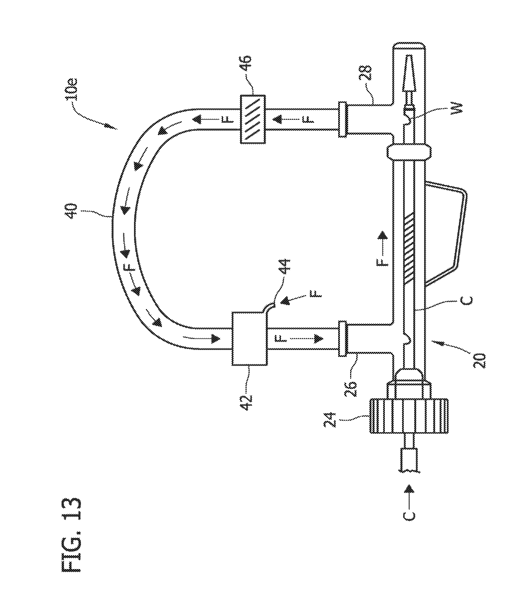
D00013

D00014

D00015

D00016

XML
uspto.report is an independent third-party trademark research tool that is not affiliated, endorsed, or sponsored by the United States Patent and Trademark Office (USPTO) or any other governmental organization. The information provided by uspto.report is based on publicly available data at the time of writing and is intended for informational purposes only.
While we strive to provide accurate and up-to-date information, we do not guarantee the accuracy, completeness, reliability, or suitability of the information displayed on this site. The use of this site is at your own risk. Any reliance you place on such information is therefore strictly at your own risk.
All official trademark data, including owner information, should be verified by visiting the official USPTO website at www.uspto.gov. This site is not intended to replace professional legal advice and should not be used as a substitute for consulting with a legal professional who is knowledgeable about trademark law.