Endobronchial tube with integrated image sensor and a cleaning nozzle arrangement
Daher Sept
U.S. patent number 10,406,309 [Application Number 13/737,944] was granted by the patent office on 2019-09-10 for endobronchial tube with integrated image sensor and a cleaning nozzle arrangement. This patent grant is currently assigned to AMBU A/S. The grantee listed for this patent is ETView Ltd.. Invention is credited to Elias Daher.


View All Diagrams
| United States Patent | 10,406,309 |
| Daher | September 10, 2019 |
Endobronchial tube with integrated image sensor and a cleaning nozzle arrangement
Abstract
An endobronchial tube which contains an integrated camera and light source and a cleaning nozzle arrangement disposed within dedicated peripheral lumen within the tube's wall.
| Inventors: | Daher; Elias (Bielefeld, DE) | ||||||||||
|---|---|---|---|---|---|---|---|---|---|---|---|
| Applicant: |
|
||||||||||
| Assignee: | AMBU A/S (Ballerup,
DK) |
||||||||||
| Family ID: | 46262117 | ||||||||||
| Appl. No.: | 13/737,944 | ||||||||||
| Filed: | January 10, 2013 |
Prior Publication Data
| Document Identifier | Publication Date | |
|---|---|---|
| US 20140031622 A1 | Jan 30, 2014 | |
Related U.S. Patent Documents
| Application Number | Filing Date | Patent Number | Issue Date | ||
|---|---|---|---|---|---|
| PCT/IB2012/052077 | Apr 26, 2012 | ||||
| 61506210 | Jul 11, 2011 | ||||
| Current U.S. Class: | 1/1 |
| Current CPC Class: | A61B 1/12 (20130101); A61B 1/00124 (20130101); A61B 1/07 (20130101); A61M 16/0057 (20130101); A61B 1/00082 (20130101); A61B 1/0676 (20130101); A61M 16/0488 (20130101); A61B 1/05 (20130101); A61B 1/313 (20130101); A61M 16/104 (20130101); A61B 1/012 (20130101); A61B 1/2676 (20130101); A61M 16/0465 (20130101); A61B 1/00018 (20130101); A61B 1/0684 (20130101); A61M 16/0461 (20130101); A61M 16/0463 (20130101); A61M 16/0459 (20140204); A61M 16/0486 (20140204); A61M 16/0833 (20140204); A61M 16/0434 (20130101); A61B 1/00094 (20130101); A61B 1/051 (20130101); A61M 16/0404 (20140204); A61B 1/015 (20130101); A61B 1/126 (20130101); A61B 1/00091 (20130101); A61M 16/04 (20130101); A61M 15/00 (20130101) |
| Current International Class: | A61B 1/12 (20060101); A61B 1/00 (20060101); A61B 1/267 (20060101); A61B 1/012 (20060101); A61B 1/05 (20060101); A61M 16/04 (20060101); A61B 1/06 (20060101); A61B 1/07 (20060101); A61B 1/313 (20060101); A61M 16/00 (20060101); A61M 16/10 (20060101); A61B 1/015 (20060101); A61M 16/08 (20060101); A61M 15/00 (20060101) |
| Field of Search: | ;600/114-116,120,156-158 ;604/264,275-279,295 ;128/200.26,207.14,207.15 |
References Cited [Referenced By]
U.S. Patent Documents
| 543616 | July 1895 | Dow |
| 1246339 | November 1917 | Smit |
| 2797683 | July 1957 | Aiken |
| 3350553 | October 1967 | Cline |
| 3539794 | November 1970 | Rauhut et al. |
| 3576987 | May 1971 | Voight et al. |
| 3716047 | February 1973 | Moore et al. |
| 3729425 | April 1973 | Andress et al. |
| 3776222 | December 1973 | Smiddy |
| 3808414 | April 1974 | Roberts |
| 3893938 | July 1975 | Rauhut |
| 4150676 | April 1979 | Jackson |
| 4253447 | March 1981 | Moore |
| 4383534 | May 1983 | Peters |
| 4437458 | March 1984 | Upsher |
| 4509507 | April 1985 | Yabe |
| 4567882 | February 1986 | Heller |
| 4602281 | July 1986 | Nagasaki et al. |
| 4616631 | October 1986 | Takahashi |
| 4635166 | January 1987 | Cameron |
| 4643170 | February 1987 | Miyazaki |
| 4742819 | May 1988 | George |
| 4759346 | July 1988 | Nakajima |
| 4813431 | March 1989 | Brown |
| 4814949 | March 1989 | Elliott |
| 4846153 | July 1989 | Berci |
| 4877016 | October 1989 | Kantor et al. |
| 4884133 | November 1989 | Kanno |
| 4998972 | March 1991 | Chin et al. |
| 5005573 | April 1991 | Buchanan |
| 5065755 | November 1991 | Klafta |
| 5179938 | January 1993 | Lonky |
| 5193544 | March 1993 | Jaffe |
| 5207213 | May 1993 | Auhll et al. |
| 5241170 | August 1993 | Field, Jr. |
| 5241956 | September 1993 | Brain |
| 5249571 | October 1993 | Brain |
| 5282464 | February 1994 | Brain |
| 5285778 | February 1994 | Mackin |
| 5287848 | February 1994 | Cubb et al. |
| 5297547 | March 1994 | Brain |
| 5305743 | April 1994 | Brain |
| 5329938 | July 1994 | Lonky |
| 5329940 | July 1994 | Adair |
| 5348690 | September 1994 | Cohen et al. |
| 5355879 | October 1994 | Brain |
| 5363838 | November 1994 | George |
| 5373317 | December 1994 | Salvati |
| 5400771 | March 1995 | Pirak |
| 5457613 | October 1995 | Vandenbelt et al. |
| 5488544 | January 1996 | Ladyjensky |
| 5499625 | March 1996 | Frass et al. |
| 5527261 | June 1996 | Monroe |
| 5552968 | September 1996 | Ladyjensky |
| 5569300 | October 1996 | Redmon |
| 5580147 | December 1996 | Salerno |
| 5607386 | March 1997 | Flam |
| 5622182 | April 1997 | Jaffe |
| 5665052 | September 1997 | Bullard |
| 5666222 | September 1997 | Ning |
| 5676635 | October 1997 | Levin |
| 5702351 | December 1997 | Bar-Or |
| 5716329 | February 1998 | Dieter |
| 5718666 | February 1998 | Alarcon |
| 5725476 | March 1998 | Yasui et al. |
| 5735792 | April 1998 | Vanden Hoek |
| 5775322 | July 1998 | Silverstein et al. |
| 5792053 | August 1998 | Skladnev |
| 5800344 | September 1998 | Wood |
| 5803898 | September 1998 | Bashour |
| 5819727 | October 1998 | Linder |
| 5827178 | October 1998 | Berall |
| 5873814 | February 1999 | Adair |
| 5873818 | February 1999 | Rothfels |
| 5879304 | March 1999 | Shuchman |
| 5888195 | March 1999 | Schneider |
| 5888196 | March 1999 | Bonutti |
| 5891013 | April 1999 | Thompson |
| 5904648 | May 1999 | Arndt |
| 5908294 | June 1999 | Schick |
| 5913816 | June 1999 | Sanders |
| 5941816 | August 1999 | Barthel et al. |
| 5944654 | August 1999 | Crawford |
| 6004265 | December 1999 | Hsu et al. |
| 6024697 | February 2000 | Pisarik |
| 6050713 | April 2000 | O'Donnell et al. |
| 6067985 | May 2000 | Islava |
| 6079409 | June 2000 | Brain |
| 6091453 | July 2000 | Coan |
| 6115523 | September 2000 | Gravenstein |
| 6126592 | October 2000 | Proch et al. |
| 6142144 | November 2000 | Pacey |
| 6142935 | November 2000 | Flom et al. |
| 6161537 | December 2000 | Gravenstein et al. |
| 6164277 | December 2000 | Merideth |
| 6176824 | January 2001 | Davis |
| 6186944 | February 2001 | Tsai |
| 6189533 | February 2001 | Simon et al. |
| 6228025 | May 2001 | Hipps et al. |
| 6248060 | June 2001 | Buess et al. |
| 6260994 | July 2001 | Matsumoto |
| 6266547 | July 2001 | Walker |
| 6318887 | November 2001 | Matsumoto |
| 6322498 | November 2001 | Gravenstein |
| 6331156 | December 2001 | Haefele |
| 6419262 | July 2002 | Fendt et al. |
| 6419626 | July 2002 | Yoon |
| 6432042 | August 2002 | Bashour |
| 6447446 | September 2002 | Smith et al. |
| 6449006 | September 2002 | Shipp |
| 6458076 | October 2002 | Pruitt |
| 6478730 | November 2002 | Bala et al. |
| 6533722 | March 2003 | Nakashima |
| 6543447 | April 2003 | Pacey |
| 6551240 | April 2003 | Henzler |
| 6616600 | September 2003 | Pauker |
| 6628335 | September 2003 | Numazaki |
| 6648816 | November 2003 | Irion |
| 6655377 | December 2003 | Pacey |
| 6692431 | February 2004 | Kazakevich |
| 6712760 | March 2004 | Sano et al. |
| 6730019 | May 2004 | Irion |
| 6741286 | May 2004 | Meek |
| 6796939 | September 2004 | Hirata et al. |
| 6847394 | January 2005 | Hansen |
| 6923176 | August 2005 | Ranzinger |
| 6929600 | August 2005 | Hill |
| 7013899 | March 2006 | Alfery |
| 7052456 | May 2006 | Simon |
| 7057639 | June 2006 | Spoonhower |
| 7128071 | October 2006 | Brain |
| 7159590 | January 2007 | Rife |
| 7297105 | November 2007 | Mackin |
| 7384308 | June 2008 | Boehnlein |
| 7458375 | December 2008 | Schwartz |
| 7530946 | May 2009 | Hartwick |
| 7584534 | September 2009 | Pease |
| 7658708 | February 2010 | Schwartz |
| 7758495 | July 2010 | Pease |
| 7862173 | January 2011 | Ellman |
| 7878973 | February 2011 | Yee |
| 7938119 | May 2011 | Chen |
| 7942813 | May 2011 | Mackin |
| 7946981 | May 2011 | Cubb |
| 7976459 | July 2011 | Laser |
| 8038606 | October 2011 | Otawara |
| 8042545 | October 2011 | Schwartz |
| 8047215 | November 2011 | Sasaki |
| 8226571 | July 2012 | Landesberg |
| 8231524 | July 2012 | Schwartz |
| 8413658 | April 2013 | Williams |
| 8458844 | June 2013 | Vazales |
| 8473033 | June 2013 | Wood et al. |
| 8479739 | July 2013 | Hirsh |
| 8534287 | September 2013 | Vazales |
| 8584678 | November 2013 | Pol |
| 8696548 | April 2014 | Gilboa |
| 8696685 | April 2014 | Gilboa |
| 8790270 | July 2014 | Landesberg |
| 8863746 | October 2014 | Totz |
| 8887730 | November 2014 | Wood |
| 8932207 | January 2015 | Greenburg |
| 8978657 | March 2015 | Sandmore et al. |
| 8998798 | April 2015 | Hayman |
| 9055881 | June 2015 | Gilboa |
| 9155854 | October 2015 | Hayman |
| 9204794 | December 2015 | Lisogurski et al. |
| 9211060 | December 2015 | Waldron et al. |
| 9242058 | January 2016 | Hayman et al. |
| 9271803 | March 2016 | Averbuch et al. |
| 9283342 | March 2016 | Gardner |
| 9332891 | May 2016 | Vazales |
| 9357905 | June 2016 | Molnar |
| 9415179 | August 2016 | Molnar |
| 9572946 | February 2017 | Chun |
| 9579012 | February 2017 | Vazales |
| 9603515 | March 2017 | Zocca |
| 9662466 | May 2017 | Gunday |
| 9750913 | September 2017 | Schwartz |
| 9788755 | October 2017 | Hayman |
| 9801535 | October 2017 | Turnbull |
| 9820642 | November 2017 | Law |
| 9826892 | November 2017 | Dresher |
| 9854962 | January 2018 | McGrail |
| 9855111 | January 2018 | Vazales |
| 9888832 | February 2018 | Schwartz |
| 9907624 | March 2018 | Vazales |
| 2001/0023312 | September 2001 | Pacey |
| 2001/0028227 | October 2001 | Lys |
| 2002/0007110 | January 2002 | Irion |
| 2002/0045801 | April 2002 | Niida |
| 2002/0062062 | May 2002 | Belson et al. |
| 2002/0072680 | June 2002 | Williams |
| 2002/0076280 | June 2002 | Semotiuk |
| 2002/0077527 | June 2002 | Aydelotte |
| 2002/0108610 | August 2002 | Christopher |
| 2002/0120181 | August 2002 | Irion |
| 2002/0162557 | November 2002 | Simon et al. |
| 2002/0193664 | December 2002 | Ross et al. |
| 2003/0011538 | January 2003 | Lys |
| 2003/0018237 | January 2003 | Okada |
| 2003/0028078 | February 2003 | Glukhovsky |
| 2003/0030745 | February 2003 | Meek |
| 2003/0035048 | February 2003 | Shipp |
| 2003/0042493 | March 2003 | Kazakevich |
| 2003/0050534 | March 2003 | Kazakevich |
| 2003/0051733 | March 2003 | Kotmel et al. |
| 2003/0078476 | April 2003 | Hill |
| 2004/0044269 | March 2004 | Shibata |
| 2004/0143167 | July 2004 | Branch et al. |
| 2004/0210114 | October 2004 | Simon |
| 2005/0039754 | February 2005 | Simon |
| 2005/0065496 | March 2005 | Simon et al. |
| 2005/0090712 | April 2005 | Cubb |
| 2007/0215162 | September 2007 | Glassenberg et al. |
| 2008/0146879 | June 2008 | Pacey |
| 2008/0188715 | August 2008 | Fujimoto |
| 2008/0200764 | August 2008 | Okada |
| 2009/0227998 | September 2009 | Aljuri |
| 2009/0253964 | October 2009 | Miyamoto |
| 2010/0113916 | May 2010 | Kumar |
| 2010/0249639 | September 2010 | Bhatt |
| 2011/0197888 | August 2011 | Deutsch |
| 2011/0282148 | November 2011 | Kase et al. |
| 2011/0313347 | December 2011 | Zocca et al. |
| 2011/0315147 | December 2011 | Wood et al. |
| 2012/0041534 | February 2012 | Clerc et al. |
| 2012/0044153 | February 2012 | Clerc |
| 2012/0065469 | March 2012 | Allyn |
| 2012/0172664 | July 2012 | Hayman et al. |
| 2012/0172665 | July 2012 | Allyn |
| 2012/0197086 | August 2012 | Morris et al. |
| 2012/0226100 | September 2012 | Greenburg |
| 2012/0259173 | October 2012 | Waldron et al. |
| 2012/0302833 | November 2012 | Hayman et al. |
| 2013/0158351 | June 2013 | Daher et al. |
| 2013/0269703 | October 2013 | Wood |
| 2013/0303849 | November 2013 | Allyn |
| 2013/0317339 | November 2013 | Waldstreicher |
| 2013/0324798 | December 2013 | Molnar et al. |
| 2014/0024893 | January 2014 | Allyn |
| 2014/0024895 | January 2014 | Allyn |
| 2014/0033455 | February 2014 | Vazales |
| 2014/0046142 | February 2014 | Gavriely |
| 2014/0094651 | April 2014 | Allyn |
| 2014/0094652 | April 2014 | Allyn |
| 2014/0094653 | April 2014 | Allyn |
| 2014/0128672 | May 2014 | Daher |
| 2014/0150782 | June 2014 | Vazales et al. |
| 2014/0221921 | August 2014 | Gilboa |
| 2014/0309494 | October 2014 | Molnar |
| 2015/0099927 | April 2015 | Ali |
| 2015/0126808 | May 2015 | Roze |
| 2015/0133741 | May 2015 | Gill |
| 2015/0174352 | June 2015 | Hayman |
| 2015/0190044 | July 2015 | Livnat |
| 2015/0223668 | August 2015 | Gilboa |
| 2015/0305596 | October 2015 | Oskin et al. |
| 2015/0305650 | October 2015 | Hunter et al. |
| 2016/0000303 | January 2016 | Klein et al. |
| 2016/0030693 | February 2016 | Nakatate |
| 2016/0038008 | February 2016 | Molnar |
| 2016/0038014 | February 2016 | Molnar |
| 2016/0051221 | February 2016 | Dickhans et al. |
| 2016/0101253 | April 2016 | Alahmadi |
| 2016/0106308 | April 2016 | Field |
| 2016/0157708 | June 2016 | Daher |
| 2016/0183777 | June 2016 | Daher et al. |
| 2016/0206189 | July 2016 | Nearman |
| 2016/0227991 | August 2016 | Hayut |
| 2016/0256646 | September 2016 | Vazales |
| 2016/0287825 | October 2016 | Daher et al. |
| 2017/0119494 | May 2017 | Vazales |
| 201862108 | Jun 2011 | CN | |||
| 4132687 | Apr 1993 | DE | |||
| 29805624 | Jul 1998 | DE | |||
| 0712601 | May 1996 | EP | |||
| 2357856 | Jul 2001 | GB | |||
| 03258268 | Nov 1991 | JP | |||
| 622902 | Feb 1994 | JP | |||
| 06217933 | Aug 1994 | JP | |||
| 8117184 | May 1996 | JP | |||
| 08126603 | May 1996 | JP | |||
| 2001501843 | Feb 2001 | JP | |||
| 2001128925 | May 2001 | JP | |||
| 2002508982 | Mar 2002 | JP | |||
| 2002514947 | May 2002 | JP | |||
| 2009505721 | Feb 2009 | JP | |||
| 2011010685 | Jan 2011 | JP | |||
| WO2004030527 | Apr 1994 | WO | |||
| WO9428784 | Dec 1994 | WO | |||
| WO9729679 | Aug 1997 | WO | |||
| WO9814112 | Apr 1998 | WO | |||
| WO9935960 | Jul 1999 | WO | |||
| 1999045990 | Sep 1999 | WO | |||
| WO200054655 | Sep 2000 | WO | |||
| WO01/56458 | Aug 2001 | WO | |||
| WO0154565 | Aug 2001 | WO | |||
| 2002056951 | Jul 2002 | WO | |||
| WO02085194 | Oct 2002 | WO | |||
| 2003075979 | Sep 2003 | WO | |||
| 2003101516 | Dec 2003 | WO | |||
| 2004093791 | Nov 2004 | WO | |||
| 2008103448 | Aug 2008 | WO | |||
| 2010011781 | Jan 2010 | WO | |||
| 2012091859 | Jul 2012 | WO | |||
| WO 2016004302 | Jan 2016 | WO | |||
Other References
|
ISR for PCT/IL2003/000797 dated Oct. 3, 2003. cited by applicant . OA for CA 2501300 dated Aug. 30, 2011. cited by applicant . OA for CA 2501300 dated Dec. 3, 2010. cited by applicant . OA for JP 2004-541140 dated Aug. 9, 2011. cited by applicant . OA for JP 2004-541140 dated Jun. 16, 2010. cited by applicant . OA for EP 03751231.6 dated Feb. 9, 2007. cited by applicant . "Care of the Mechanically Ventilated Patient With a Tracheotomy". (1994) Chapter 35 p. 761-774. cited by applicant . Scanlan et al., "Egan's Fundamenttals of Respiratory Care", 1999, Mosby. cited by applicant . Minutes of the oral proceedings for EP03751231.6--dated Jan. 24, 2007. cited by applicant . Tobin, "Principles and Practice of Mechanical Ventilation", 1994, Artificial, Airways and Managment. Part X p. 698-729. cited by applicant . OA for EP 03751231.6 dated Oct. 17, 2006. cited by applicant . OA for EP 03751231.6 dated Mar. 29, 2007. cited by applicant . OA for EP 03751231.6 dated Sep. 27, 2005. cited by applicant . Michael Emmanuel Leventon, "A Registration, Tracking, and Visualization System for Image-Guided Surgery"--Massachusetts Institute of Technology(May 1997). cited by applicant . OA for JP 2004-541140 dated Jan. 24, 2011. cited by applicant . ISR for PCT/IB2012/052077 dated Aug. 17, 2012. cited by applicant . Adair (2001). Macintosh Lighted Stylet, located at <http://www.adair.at/eng/museum/equip/acctracheal/macintoshlighted.htm- l> last visited on Mar. 28, 2003. cited by applicant . Anonymous (2002). "Intubation-Advances Airway Management (#10102.)" Procedure 2 pages. cited by applicant . Anonymous (2003). "Anatomic Landmarks," located at <http://www.rnceus.com/resp/respthoracic.html>. cited by applicant . Birmingham et al. (1986). "Esophageal Intubation: A Review of Detection Techniques," Anesth. Analg. 65:886-891. cited by applicant . Debo, R.F. et al. (1989). "Cricoarytenoid Subluxation: Complication of Blind Intubation With a Lighted Stylet" Ear, Nose, Throat Journal vol. 68. cited by applicant . Dey, D. et al. (2000). "Mixed Reality of Merging of Endoscopic Images and 3-D Surfaces," 8 pages. cited by applicant . Graphic Solutions, Inc. (2003). Thin Flexible Battery product information sheets located at <http://www.graphicsolutionsinc.com/tfb.html> last visited on Mar. 26, 2003. 3 pages. cited by applicant . Heller, R.M. and Heller, T.W. (1994). "Experience With the Illuminated Endotracheal Tube in the Prevention of Unsafe Intubations in the Premature and Full-Term Newborn," Pediatrics 93(3):389-391. cited by applicant . Hudson RCI Brochure (No Date Available). Airway Management product sheets, pp. 1-22. cited by applicant . King, H.-K. (2002). "Soft-tip Intubating Stylet" Brief Communication: Acta Anaethesiol Sin 40:135-137. cited by applicant . Lumex, Inc. (1997-2001). T-1.88mm Stove Pipe Lens LED Lamp product sheet, located at <http://www.lumex.com/pls/lumex/subproduct.sub.--galary> last visited on Mar. 31, 2003, 1 page. cited by applicant . Lumex, Inc. (1997-2001). T-2mm Axial Leaded LED Lamp product sheet, located at <http://www.lumex.com/pls/lumex/subproduct.sub.--galary> last visited on Mar. 31, 2003, 2 pages. cited by applicant . Luxeon Dental Brochure (2002). "Power Light source" Luxeon Dental Technical Data D535, 10 pages. cited by applicant . Mercury Medical Catalog (No Date Available). Intubation Products, 24 pages. cited by applicant . Nellcor Product Brochure (2003). Hi-Lo Tracheal Tube product sheet located at <http://www.nellcor.com/prod/Product.aspx?> last visited on Mar. 27, 2003. 1 page. cited by applicant . Nellcor Puritan Bennett Inc. (2003). Disposable Cannula Cuffed Tracheostomy Tubes product information sheet located at <http://www.nellcor.com/prod/Product.aspx?> last visited on Mar. 27, 2003. cited by applicant . Nellcor Puritan Bennett Inc. (2003). Disposable Cannula Cuffless Tracheostomy Tubes Product Information sheet located at <http://www.nellcor.com.prod/Product.aspx?> last visited on Mar. 27, 2003. 1 page. cited by applicant . Nellcor Puritan Bennett Inc. (2003). EMT Emergency Medicine Tube Product Fact Sheet located at <http://www.nellcor.com/prod/Product.aspx> last visited on Mar. 27, 2003, 1 page. cited by applicant . Nellcor Puritan Bennett Inc. (2003). Laser-Flex Tracheal Tube Product Fact Sheet located at <http://www.nellcor.com/prod/Product.aspx> last visited on Mar. 27, 2003, 1 page. cited by applicant . Power Paper Ltd. Brochure (2003). Power Paper, Micro-Powered Devices, Thin and Flexible Batteries located at <http://www.powerpaper.com/3.sub.--technology/advantage.html> last visited on Mar. 27, 2003. 6 pages. cited by applicant . Quallion, LLC Product Sheet (2002). I Series Product Feature Fact Sheet, located at <http://www.quallion.com/prod.sub.--i.html> last visited on Apr. 2, 2002. 1 page. cited by applicant . Seiko Instruments, Inc. (2002) Micro Batteries Product Catalogue. 28 pages. cited by applicant . Tech:Med Brochure: Face Shields and Product Masks, pp. 21-28. (No Date Available). cited by applicant . ISR for PCT/US2004/011773 dated Apr. 7, 2005. cited by applicant . EP search report for related EP14150501 dated Jul. 2, 2014. cited by applicant . Machine translation of JP2011010685. cited by applicant . Office Action for related JP2014-519648, dated Mar. 1, 2016 (translation). cited by applicant . Office Action in corresponding EP application 12727168, dated Mar. 3, 2014. cited by applicant . Office Action for U.S. Appl. No. 14/967,048, dated Oct. 21, 2016. cited by applicant . Office Action for U.S. Appl. No. 13/819,743, dated Jul. 14, 2016. cited by applicant . Office Action for U.S. Appl. No. 13/819,743, dated Oct. 7, 2015. cited by applicant . Office Action for U.S. Appl. No. 13/819,743, dated Feb. 5, 2015. cited by applicant . Office Action for U.S. Appl. No. 14/151,846, dated Oct. 6, 2016. cited by applicant . Office Action for U.S. Appl. No. 14/151,846, dated Apr. 4, 2016. cited by applicant . Office Action for U.S. Appl. No. 14/967,048, dated Jun. 6, 2016. cited by applicant . Pre-Interview First Office Action for U.S. Appl. No. 13/819,743, dated Sep. 9, 2014. cited by applicant . Office Action issued by the U.S. Patent and Trademark Office, dated Apr. 27, 2017, for related U.S. Appl. No. 13/819,743; 9 pages. cited by applicant . Office Action issued by the U.S. Patent and Trademark Office, dated Jul. 7, 2017, for related U.S. Appl. No. 14/967,048; 11 pages. cited by applicant . Non-Final Office Action issued by the U.S. Patent and Trademark Office, dated Jan. 12, 2018, for related U.S. Appl. No. 13/819,743, 10 pages. cited by applicant . Non-Final Office Action issued by the U.S. Patent and Trademark Office, dated May 8, 2018, for related U.S. Appl. No. 14/967,048, 12 pages. cited by applicant . Non-Final Office Action issued by the U.S. Patent and Trademark Office, dated Sep. 21, 2017, for related U.S. Appl. No. 15/042,160, 9 pages. cited by applicant. |
Primary Examiner: Kasztejna; Matthew J
Attorney, Agent or Firm: Faegre Baker Daniels LLP
Parent Case Text
CROSS-REFERENCE TO RELATED APPLICATIONS
This application is a U.S. Continuation In Part Application of International Application No. PCT/IB2012/052077, filed on Apr. 26, 2012, which claims the benefit of U.S. Provisional Application Ser. No. 61/506,210, filed on Jul. 11, 2011, all of which are hereby incorporated by reference in their entirety. U.S. application Ser. No. 14/151,846, filed on Jan. 10, 2014, which issued on Dec. 11, 2018 as U.S. Pat. No. 10,149,602, is a Continuation In Part of the present application. U.S. application Ser. No. 13/819,743, filed on Feb. 28, 2013, is a National Stage Entry of PCT/IB2012/052077. U.S. application Ser. No. 14/967,048, filed on Dec. 11, 2015, and Ser. No. 15/042,160, filed on Feb. 12, 2016, are continuations of U.S. application Ser. No. 13/819,743.
Claims
What is claimed is:
1. An endobronchial tube comprising: a tube having a wall; a first lumen having a longitudinal portion and an open distal end; a first inflatable cuff located proximally of the open distal end of the first lumen; a second lumen having an open distal end; a second inflatable cuff located distally of the first lumen; a dedicated image sensor lumen in the wall comprising a circular cross-section at its distal end; an image sensor adjacent an illumination source, the image sensor and the illumination source disposed entirely within the dedicated image sensor lumen at the distal end thereof and having a cross-section that fits entirely within the circular cross-section of the distal end of the dedicated image sensor lumen, within the wall of the tube; and a dedicated cleaning nozzle arrangement wholly embedded in the wall of the tube, the dedicated cleaning nozzle arrangement comprising a longitudinal cleaning lumen disposed parallel with the dedicated image sensor lumen and angled portions fluidly coupled to and extending from the longitudinal cleaning lumen, each of the angled portions defining a cleaning nozzle consisting of an elongate aperture in the wall of the tube, connecting to and extending from the longitudinal cleaning lumen to an opening on a surface across a thickness of the wall, the surface being distal of the image sensor and substantially parallel to the longitudinal axis of the tube, thus the cleaning nozzles are arranged distally from the image sensor, wherein the cleaning nozzles comprise a first cleaning nozzle and a second cleaning nozzle, and whereby the dedicated cleaning nozzle arrangement is configured to flush a fluid through the cleaning nozzles to clear a field of view of the image sensor.
2. The endobronchial tube of claim 1, wherein a diameter of the first cleaning nozzle is larger than a diameter of the second cleaning nozzle.
3. The endobronchial tube of claim 2, wherein the diameter of the first cleaning nozzle is about 0.8 mm and the diameter of the second cleaning nozzle is about 0.6 mm.
4. The endobronchial tube of claim 1, wherein the first cleaning nozzle and the second cleaning nozzle each have a diameter from about 0.1 mm to about 2 mm.
5. The endobronchial tube of claim 1, wherein the second cleaning nozzle comprises a plurality of cleaning nozzles.
6. The endobronchial tube of claim 5, wherein the plurality of cleaning nozzles are positioned distally of the first cleaning nozzle.
7. The endobronchial tube of claim 6, wherein the plurality of cleaning nozzles are arranged in a linear fashion about a longitudinal axis of the cleaning lumen.
8. The endobronchial tube of claim 6, wherein the plurality of cleaning nozzles are arranged in an arc.
9. The endobronchial tube of claim 1, wherein the dedicated image sensor lumen is disposed within the wall of the tube between the first lumen and the second lumen.
10. The endobronchial tube of claim 1, wherein the second lumen comprises a second image sensor.
11. The endobronchial tube of claim 1, wherein the second inflatable cuff is located at a distal end of the endobronchial tube.
12. The endobronchial tube of claim 1, wherein the second inflatable cuff is angled toward the longitudinal cleaning lumen.
13. The endobronchial tube of claim 12, wherein the second inflatable cuff is dimensioned to be positioned in and to completely block either a right or left bronchus when inflated.
14. The endobronchial tube of claim 1, wherein the image sensor lumen is configured to provide an image of a tracheal bifurcation of a Tracheal Carina, an opening of a Left Bronchial branch, or an opening of a Right Bronchial branch.
15. The endobronchial tube of claim 1, wherein the cleaning nozzles are aimed proximally toward the image sensor to clear the field of view of the image sensor.
16. The endobronchial tube of claim 1, wherein at least one of the angled portions of the dedicated cleaning lumen include an open end extending through a surface of a wall forming the image sensor lumen thereby defining its respective cleaning nozzle.
Description
FIELD OF INVENTION
The present invention relates to upper airway tubes and in particular, to an endobronchial tube with an integrated image sensor and light source having a cleaning nozzle arrangement.
BACKGROUND OF THE INVENTION
Respiratory tubes for example endobronchial tubes, endotracheal tubes, tracheostomy tubes are used to ventilate at least a portion of the respiratory system or lungs of a subject. Such respiratory tubes may be inserted in a number of ways via a non-invasive approach through an orifice or cavity such as the oral or nasal cavity. Alternatively such tubes may be introduced to a body via a minimally invasive external incision creating a port for tube insertion for example through the trachea in a tracheotomy procedure.
Such respiratory tubes may be provided as double lumen tubes, or single lumen tubes for selectively ventilating a portion of the respiratory system. For example endobronchial tubes, whether, double lumen tubes or a single lumen tube may be utilized for one-lung ventilation procedures or for selective lung ventilation of the left or right bronchi, during one-lung ventilation procedures.
SUMMARY OF THE INVENTION
In order to perform one lung ventilation procedures without complications, the position of the respiratory tube placed within either the left or right bronchi and the trachea must be closely monitored or at least confirmed prior to initiating a procedure. Various technologies are available to confirm the tube's placement, for example capnograph, auscultation, bronchoscope and x-ray.
However these procedures take time, technique and skill to perform and therefore it is not feasible to continuously monitor the tube's placement.
In particularly when the subject is moved during a procedure the tube's location may change leading to potentially dangerous displacement of the tube possibly suffocating the subject or inappropriate ventilation of the patient, for example not ventilating the correct portion of the respiratory system.
Verification by means of a bronchoscope is currently the gold standard, but none of the mentioned confirmation techniques provide continuous monitoring of the carina or provide for correct tube positioning. Furthermore, drawbacks with respect to the design and sensitivity of the bronchoscope render its cleaning process elaborate and often inefficient and costly process, that may lead to cross infection between subjects.
There is an unmet need for, and it would be highly useful to have an endobronchial tube capable of continuously and seamlessly inspect the location and implantation of the endobronchial tube relative to the Tracheal Carina. Furthermore it would be advantageous to have an endobronchial tube that is capable of maintaining a clear field of view of the Tracheal Carina.
The present invention overcomes the deficiencies of the background by providing an endobronchial tube having an integrated image sensor with a corresponding light source and integrated means for maintaining the field of view provided by the image sensor, for example in the form of a cleaning nozzle and/or lumen.
A preferred embodiment of the present invention provides for a respiratory tube, preferably in the form of a double lumen endobronchial tube, designed for oral or nasal insertion via the trachea and into a lung to inspect and/or visualize the Carina, to maintain airway patency and/or deliver anesthetic, inhalation agent or other medical gases, and secure ventilation.
Most preferably the endobronchial tube of the present invention may be made of medical grade materials for example including but not limited to plastic, rubber, polymers or silicone or the like materials as is known in the art.
Most preferably the endobronchial tube of the present invention provides for continuous monitoring of the Tracheal Carina (herein "TC"), allowing a user, physician, nurse, or caregiver to verify the correct placement of the endobronchial tube while maintaining a clear field of view of the TC.
Most preferably the endobronchial tube includes an integrated image sensor, optionally and preferably in the form of a charged-coupled device ("CCD") or a complementary metal-oxide semiconductor ("CMOS") camera provided for visualizing the carina to confirm the correct placement of the tube within the trachea and bronchi, assuring correct ventilation during procedures for example including but not limited to one lung ventilation procedures, or the like.
Most preferably the integrated camera and light source provide continuous verification of the correct placement of the endobronchial tube. The continuous placement verification allows a caregiver the opportunity to detect any dangerous situation, for example cuff dislodgement, providing sufficient time to react to the situation as is necessary. Moreover blood and secretion accumulation or any other unexpected incidents during surgery, which might cause risk to the patient, may be observed.
A preferred embodiment of the present invention provides for an endobronchial tube with an integrated image sensor, for example including but not limited to a charged-coupled device ("CCD") or complementary metal-oxide semiconductor ("CMOS") camera, with a corresponding light source, for example including but not limited to a Light Emitting Diode (`LED`) while optimizing the lumen patency for both adequate airflow performance through the tube. Most preferably the image sensor and corresponding light source are provided in a dedicated lumen along the length of the endobronchial tube. Most preferably the image sensor is further provided with at least one or more adjacent and integrated cleaning nozzle to ensure an open field of view, for example of the TC, distal to the image sensor. Most preferably the integrated cleaning nozzle may be configured to be wholly embedded within the tube's wall in the form of a dedicated cleaning lumen running the length of the tube. Most preferably the length of the image sensor lumen 150L is provided paralleled with the length of the tracheal lumen, therein both tracheal lumen and image sensor lumen are of essentially the same length. Optionally the length of the image sensor lumen 150L may be provided according to the length of the bronchial lumen.
Optionally the endobronchial tube may be provided with two dedicated image sensor lumen. Optionally a first dedicated image sensor lumen is provided according to the length of the tracheal lumen and a second dedicated image sensor lumen is provided according to the length of the bronchial lumen.
A preferred embodiment of the present invention provides for an endobronchial tube having an integrated image sensor, light source and cleaning nozzle capable of providing a continuously and unobstructed view and illumination of the carina, left bronchi, right bronchi, bronchial cuff and bronchial bifurcations, within a single field of view.
Optionally and preferably the tube of the present invention utilizes at least one or more bronchial cuff. Optionally at least two or more bronchial cuffs may be utilized to provide adequate sealing of the bronchi.
Optionally the bronchial cuff may be provided in varying shapes so as to better fit the bronchi for example include but is not limited to spherical, elliptical, helical, hourglass, trapezoidal, or the like.
Optionally different bronchial cuff configured and shaped according to anatomy and placement location, for example anatomy based on configuration of a cuff for left bronchi placement and for right bronchi placement. Within the context of this application the term endobronchial tube may be used interchangeably with any one of Tracheobronchial tube, double lumen tube, double lumen endobronchial tube, double lumen endotracheal tube, to collectively refer to a tube and/or catheter utilized for selectively ventilating a subject via both lungs, one of the lungs or a portion of one or both of the lungs.
An endobronchial tube comprising an external wall and an internal septum defining at least two ventilation lumen of different lengths for selectively associating with a patient about at least two locations relative to the Tracheal Carina, the tube comprising:
a first ventilation lumen having an open distal end that associates proximally to the Carina within the Trachea, with a first inflatable cuff; and
a second ventilation lumen having an open distal end that extends distally, past the Carina and associates within one of the Left Bronchial branch or Right Bronchial branch with a second inflatable cuff;
the tube further comprising at least two peripheral lumen of different lengths, that are disposed within the tube's external wall and running parallel with the at least the first ventilation lumen;
the first peripheral lumen comprises an image sensor and light source disposed proximal to the distal end of the first ventilation lumen, and configured to provide an image of the Tracheal bifurcation of the Tracheal Carina, the openings of the Left Bronchial branch, and the opening Right Bronchial branch;
the second peripheral lumen defining a dedicated cleaning lumen, having a distal end disposed distally to the distal end of the first peripheral lumen about the image sensor and light source, the second peripheral lumen having a distal end having a plurality of variably sized openings, wherein each opening forms a cleaning nozzle distal to the image sensor, the second peripheral lumen configured to conduct a flowing fluid to maintain a clear field of view distal to the image sensor.
Optionally and preferably the distal end of the second peripheral lumen comprises four openings defining four cleaning nozzles about the image sensor. The four openings are preferably arranged distally to one another in a linear sequential manner. The first opening having an opening of about 0.8 mm defining the first cleaning nozzle directly adjacent to the image sensor. The remaining three openings may be configured to have a nozzle opening of about 0.6 mm.
Optionally the cleaning nozzles may be variably spaced relative to one another and/or may be uniformly spaced relative to one another about the distal end of the second peripheral lumen.
Optionally, the tube may further comprise additional peripheral lumen running along the second ventilation lumen providing for a second image sensor and light source providing an image of the Right bronchi or Left bronchi, and dedicated cleaning lumen.
Optionally the first and second peripheral lumen may run parallel with the second ventilation lumen rather than the first ventilation lumen.
Optionally the image sensor may be a CCD image sensor or CMOS Image sensor.
Optionally, the first peripheral lumen further comprises a light source disposed proximal to the distal end and adjacent to the image sensor.
Optionally the light source may be selected from the group consisting of a LED, optical fiber, waveguide, light guide, and any combination thereof.
Optionally the first peripheral lumen comprising an image sensor and light source may be disposed within a dedicated channel embedded within a wall of the first lumen.
Most preferably the image sensor may be associated with an auxiliary device for example including but not limited to a display and power supply at the proximal end of the tube most preferably about the first lumen, through a single dedicated connector for example including but not limited to a USB connector.
Optionally the endotracheal tube may be adapted for non-invasive insertion through the oral cavity or nasal cavity.
Optionally the endotracheal tube may be adapted for insertion through an external port or incision.
Optionally the endotracheal tube may be adapted for insertion through a surgical procedure or other invasive procedure.
Unless otherwise defined, all technical and scientific terms used herein have the same meaning as commonly understood by one of ordinary skill in the art to which this invention belongs. The materials, methods, and examples provided herein are illustrative only and not intended to be limiting.
BRIEF DESCRIPTION OF THE DRAWINGS
The invention is herein described, by way of example only, with reference to the accompanying drawings. With specific reference now to the drawings in detail, it is stressed that the particulars shown are by way of example and for purposes of illustrative discussion of the preferred embodiments of the present invention only, and are presented in order to provide what is believed to be the most useful and readily understood description of the principles and conceptual aspects of the invention. In this regard, no attempt is made to show structural details of the invention in more detail than is necessary for a fundamental understanding of the invention, the description taken with the drawings making apparent to those skilled in the art how the several forms of the invention may be embodied in practice.
FIGS. 1A-B show schematic illustrations of an exemplary endobronchial tube according to an optional embodiment of the present invention; FIG. 1A shows the endobronchial tube within the right bronchi; FIG. 1B shows the endobronchial tube within the left bronchi;
FIG. 2 shows a schematic sectional view of the Tracheal Carina as seen from the endobronchial tube according to an optional embodiment of the present invention;
FIG. 3 shows a perspective view of an exemplary endobronchial tube according to an optional embodiment of the present invention;
FIG. 4A shows a perspective view of an exemplary endobronchial tube according to an optional embodiment of the present invention;
FIG. 4B shows a close up view of notch exit point for the image sensor connector according to the present invention;
FIG. 5 shows a perspective view of exemplary endobronchial tube according to an optional embodiment of the present invention;
FIG. 6 shows a perspective view of exemplary endobronchial tube according to an optional embodiment of the present invention, depicting the curvature of the tube;
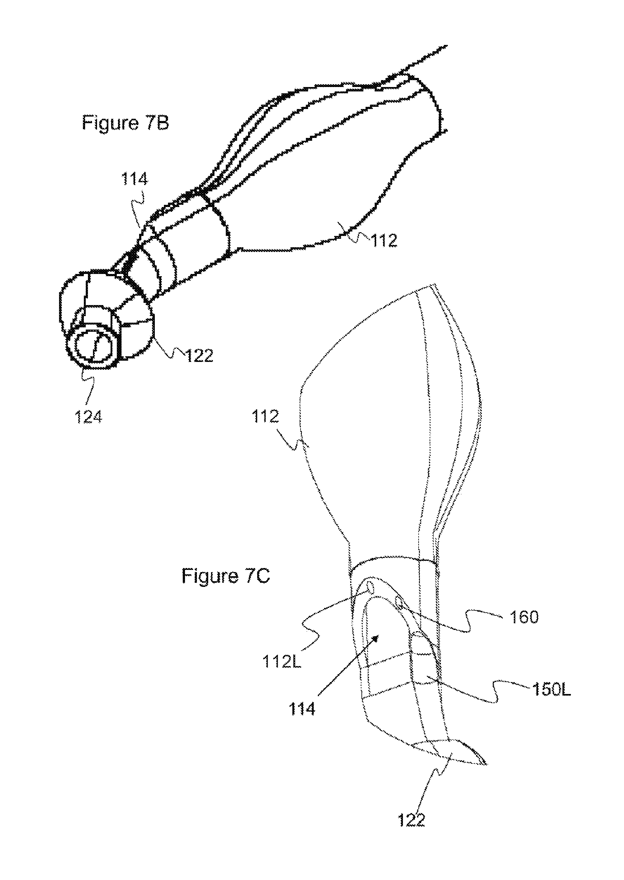
FIGS. 7A-F shows varying close up views of the distal end of the endobronchial tube according to optional embodiments of the present invention;
FIGS. 7G-H show a preferred embodiment of the cleaning nozzle arrangement according to the present invention;
FIG. 71 shows an optional embodiment according to the present invention;
FIGS. 8A-B show cross-sectional views about different portions of the endobronchial tube according to optional embodiments of the present invention;
FIG. 9 shows a close up view of the image sensor with integrated light source within a dedicated lumen disposed within the wall of the endobronchial tube according to an optional embodiment of the present invention; and
FIG. 10 illustrates a side view of a section of the endobronchial tube.
DESCRIPTION OF THE PREFERRED EMBODIMENTS
The principles and operation of the present invention may be better understood with reference to the drawings and the accompanying description. The following reference labels listed below are used throughout the drawings to refer to objects having similar function, meaning, role, or objective. 10 Stylet; 12 Y-connector; 14 Air Balance Cap; 20 Endobronchial Tube connector assembly; 22 Endobronchial Tube connector proximal end; 24 Tracheal lumen connector portion; 26 Bronchial lumen connector portion; 28 Endobronchial Tube connector distal end; 50 endobronchial tube system; 100 endobronchial tube; 100w tube external wall; 101 sectional view; 102 tube proximal end; 104 tube distal end; 104a distal curvature; 106 tube medial portion; 106a medial curvature; 108 midline partition; 110 tracheal lumen; 111 tracheal lumen connector; 112 tracheal cuff; 112n tracheal cuff notch; 114 tracheal lumen distal end; 116 tracheal lumen proximal end; 118 tracheal cuff connector; 120 bronchial lumen; 122 bronchial cuff; 124 bronchial lumen distal end; 126 bronchial lumen proximal end; 128 bronchial cuff connector; 130 injection tube connector; 150 image sensor arrangement; 150c image sensor; 150d image sensor lumen distal end; 150I illumination source; 150L image sensor lumen; 152 image sensor notch; 154 image sensor conductor; 156 image sensor single cleaning nozzle; 158 image sensor connector; 160 cleaning lumen; 160d cleaning lumen distal end; 162 cleaning nozzle arrangement; 164 four cleaning nozzle arrangement; 166 primary cleaning nozzle; 168 secondary cleaning nozzles; TR Trachea; TC Tracheal Carina; BR Right Bronchi; BL Left Bronchi.
FIG. 1A shows a schematic illustration of an exemplary endobronchial tube 100 according to an optional embodiment of the present invention placed within the right bronchi (BR). FIG. 1B shows a schematic illustration of an endobronchial tube 100 within the left bronchi(BL).
Endobronchial tube 100 is a dual lumen tube comprising an external wall 100w, a first tracheal ventilation lumen 110 and a second bronchial ventilation lumen 120. Most preferably wall 100w is a common to both tracheal lumen 110 and bronchial lumen 120 wherein wall 100w most preferably defines the external surface of tube 100. Most preferably an internal septum and/or midline partition 108 defines the individual lumen into tracheal lumen 110 and bronchial lumen 120, FIGS. 8A-B. Tracheal lumen 110, most preferably, has a distal end 114 ending within the trachea while the bronchial lumen 120 has a distal end 124 endings within the bronchi, left or right. Therein tracheal lumen 110 and bronchial lumen 120 are configured to have different lengths, wherein the bronchial lumen 120 extends past and/or distally to tracheal lumen 110.
Most preferably each ventilation lumen comprising an inflatable cuff respectfully, tracheal cuff 112 and bronchial cuff 122. Optionally and preferably cuffs 112 and 122 are individually controllable. Tube 100 is places such that the tracheal lumen 110 is placed within the Trachea by way of cuff 112 proximally, above, the tracheal carina (`TC`). Most preferably the tracheal carina may be continually visualized with an image sensor 150c and light source 150L, FIG. 9.
Most preferably wall 100w of tube 100 comprises a plurality of dedicated peripheral lumen dispersed about the periphery of wall 100w, FIGS. 8A-B. Most preferably tube 100 comprises at least two or more dedicated peripheral lumen; a first dedicated peripheral lumen provided as an image sensor lumen 150L provided for imaging the TC; and a second dedicated peripheral lumen provided in the form of a dedicated cleaning lumen 160 for clearing and/or cleaning the view of image sensor disposed in image sensor lumen 150L.
Most preferably tube 100 according to the present invention is characterized in that it comprises a cleaning nozzle arrangement 162 about distal end 160d, FIGS. 7G-H. Most preferably cleaning nozzle arrangement 162 comprises a plurality of cleaning nozzles arranged about the distal end 160d and distally to image sensor arrangement 150 so as to ensure that a tube 100 is provided with a clear and unobstructed view of the TC, for example as shown in FIG. 2. Most preferably cleaning nozzle arrangement are optionally and preferably directed and/or aimed to clear the field of view immediately distal to image sensor arrangement 150 about the distal end 114 of tracheal ventilation lumen 110.
Optionally and most preferably cleaning nozzle arrangement 162 may comprise at least two or more cleaning nozzles about distal end 160d. Most preferably a cleaning nozzle arrangement 162 comprising a plurality of cleaning nozzles about distal end 160d provides sufficient flushing and/or cleaning power and/or force and/or pressure so as to provide image sensor arrangement 150 with an unobstructed view by evacuating biological debris for example mucus or the like biological builds up in and about distal end 114, 150d and 160d.
Most preferably cleaning nozzle arrangement 162 comprises a four cleaning nozzle arrangement 164 about image sensor arrangement 150. Four cleaning nozzle arrangement 164 includes a first primary cleaning nozzle 166 and at least three secondary cleaning nozzles collectively referred to as 168, as shown in FIGS. 7G-H.
Most preferably arrangement 164 may be arranged distally to one another in a linear sequential manner for example as shown in FIG. 7G-H. Most preferably primary cleaning nozzle 166 may be configured to have a nozzle opening of about 0.8 mm, and is most preferably disposed immediately and/or directly adjacent to the image sensor arrangement 150.
Most preferably secondary cleaning nozzles 168 may be configured to have a nozzle opening of about 0.6 mm, and a disposed distally to primary cleaning nozzle 166.
Optionally secondary cleaning nozzles 168 may optionally be spaced apart equally, for example about 0.5 mm. Optionally secondary cleaning nozzles 168 may be spaced unequally distal to primary cleaning nozzle 164.
Optionally cleaning nozzle arrangement 162 about distal end 160d may be configured in optional geometric arrangements, wherein primary cleaning nozzle 166 is disposed nearest to image sensor arrangement 150 providing a first flushing and/or cleaning activity, while a plurality of secondary cleaning nozzle 168 are arranged distally thereto to provide a secondary flushing and/or cleaning activity, FIG. 71.
Optionally cleaning nozzles 166, 168 may be provided with an opening having a diameter from about 0.1 mm to about 2 mm. Optionally primary cleaning nozzle 166 has a larger nozzle opening diameter than do secondary cleaning nozzles 168.
Most preferably image sensor 150c and light source 150l are disposed within a first dedicated peripheral image sensor lumen 150L that is most preferably disposed within wall 110w. Optionally and most preferably image sensor lumen 150L comprising image sensor 150c and light source 150l may be integrated within tracheal lumen 110 about distal end 114, such that the distal end 150d is adjacent to distal end 114. Optionally and most preferably the image sensor arrangement 150 remains within its dedicated peripheral image sensor lumen 150L. Optionally and most preferably image sensor arrangement 150, FIG. 9, comprising an image sensor 150c and a light source 150l may be integrated within a dedicated channel or peripheral image sensor lumen 150L within a wall of the tracheal lumen 110. Most preferably image sensor arrangement 150 provides a cross sectional view 101, for example as shown in FIG. 2.
Most preferably image sensor arrangement 150 are provided in the form of at least one or more light emitting diode (`LED`) 150l and image sensor 150c for example including but not limited to a charged-coupled device ("CCD") or a complementary metal-oxide semiconductor ("CMOS"), (FIG. 9) providing a view 101 showing the status of the bronchi, FIG. 2.
FIG. 2 shows a schematic sectional view of the Tracheal Carina as seen from endobronchial tube 100, provided by image sensor and light source 150, allowing the visualization of bronchial cuff 122 disposed within the left bronchi BL, the patency of the left bronchi, the patency of the right bronchi, the tracheal carina, bronchial bifurcation, in a single field of view 101. Optionally a similar view may be provided with image sensor arrangement 150 when tube 100 is disposed with the right Bronchi BR as shown in FIG. 1A.
FIG. 3 shows endobronchial double lumen tube system 50 comprising endobronchial tube 100 and optional various auxiliary devices that may be used in conjunction with and/or facilitate the use of tube 100.
Optionally auxiliary devices may for example include but are not limited to stylet 10, Y-connector 12, air balance caps 14, and an endobronchial tube connector assembly 20, or the like adjunct device utilized facilitating the use of tube 100 as is known in the art.
Stylet 10 most preferably is utilized to facilitate placement of tube 100, as is known and accepted in the art.
Y-connector 12 most preferably provides for simultaneously connecting both lumens of double lumen tube 100 to a single ventilation source.
Endobronchial Tube connector assembly 20 provides for individually connecting to tracheal lumen 110 and bronchial lumen 120. Connector assembly 20 comprises a proximal end 22, distal end 28, and respective Tracheal lumen connector portion 24 and Bronchial connector portion 26.
Most preferably proximal end 22 provides for connecting and/or otherwise associating the tube 100 at proximal end 102 at about the individual lumen tracheal lumen 110 and bronchial lumen 120 to auxiliary devices for example including but not limited to ventilation sources.
Most preferably distal end 24 provides for coupling and/or otherwise associating with tube 100.
FIG. 3 further provides a perspective view of a preferred double lumen endobronchial tube 100 comprising tracheal lumen 110 having a tracheal lumen distal end 114 and bronchial lumen 120 having a bronchial lumen distal end 124.
Tube 100 further comprises tracheal cuff 112, shown in its expanded state, provided for securely placing and/or anchoring tube 100 within the trachea while ventilating the lungs through tracheal lumen 110.
Tube 100 further comprises bronchial cuff 122, shown in its expanded and/or inflated state, provided for securely placing and/or anchoring tube 100 within the bronchi, left or right. Most preferably cuff 122 provides for selectively controlling the ventilation to the bronchial arch wherein it is placed (left or right). For example ventilation to either the left or right bronchi may be completely blocked so as to allow a procedure on the respective lung (for example right) while allowing the ventilation of the other lung (for example left) via tracheal lumen 110.
Most preferably tracheal cuff 112 may be inflated and/or deflated via cuff tracheal connector 118.
Most preferably bronchial cuff 122 may be inflated and/or deflated via cuff bronchial connector 128.
Most preferably injection tube connector 130 provides an access point to a dedicated lumen about each of the tracheal tube 110 and bronchial tube 120, preferably for delivering drugs, suctioning liquids about tracheal distal 114 and/or bronchial lumen distal end 124.
FIG. 4A provides a further perspective view of endobronchial tube 100, showing image sensor connector 158. Most preferably image sensor connector 158 is provided in the form of a USB connector that provides both for image and power supply to image sensor arrangement 150 disposed in a dedicated lumen near distal end 114. Optionally and preferably image sensor 150c and illumination source 150l may be rendered functional when connected to a display and power source (not shown) via connector 158.
FIG. 4B provides a close up view showing the image sensor notch 152 disposed about the proximal end of image sensor lumen 150L providing an exit point for image sensor image sensor conductors 154, most preferably provided for both image transfer and power supply to image sensor 150c and illumination source 150I.
FIG. 5 provides a further perspective view of tube 100 provided from a face on view showing the separation of tracheal lumen 110 and bronchial lumen 120 at distal end 104 of tube 100.
FIG. 6 provides a further schematic illustrative depiction of tube 100 showing a perspective view of tube 100 with the bronchial cuff 122 and tracheal cuff 112 removed. FIG. 6A shows the curvature provided at both the medial section 106 and distal end 104 therein defining a medial curvature 106a and a distal curvature 104a. Curvatures 104a and 106a are provided to so that tube 100 fits within the upper airway tract's anatomy.
Most preferably medial curvature 106a is provided for the ease of accessing and introducing tube 100 within the trachea through the oral cavity and pharynx. Most preferably, curvature 106a, is provided with an angle from about 100 degrees to about 160 degrees.
Most preferably distal curvature 104a is provides for ease of accessing and introducing distal end 104 into one of the bronchi, left or right.
Optionally and preferably distal curvature 104a may be specific for individual left or right endobronchial tubes. Optionally distal curvature may be configured to be from about 25 degrees to about 70 degrees. Optionally and preferably about 35 degrees as shown.
Optionally the length of tube 100 may be provided with a length from about 200 mm to about 550 mm. Optionally and preferably the length of tube 100 may be selected in accordance with a user's anatomy.
Optionally endobronchial tube 100 may be provided with different sizes, length, diameters as known and accepted in the art. Optionally tube 100 may be provided with a gauge from about 26 Fr to about 44 Fr, or from about For example the external diameter of tube 100 may be provided in varying gauges and/or sizes for example including but not limited to 28 Fr, 32 Fr, 35 Fr, 37 Fr, 39 Fr and 41 Fr, within the context of this application the units `Fr` refer to the gauge of the tube 100 in the units French as is a common term of the art. Alternatively the gauge and or size of tube 100 may be provided in the SI units of millimeters `mm`. The tube 100 according to the present invention may be provided with an external diameter of about 9.3 mm, 10.7 mm, 11.7 mm, 13 mm and 13.7 mm.
Optionally and preferably the length and diameter (also referred to as gauge) of tube 100 may be correlated with one another.
FIG. 7A shows a close up view of distal end 104 of tube 100 shown in FIG. 6 providing a close up view. FIG. 7A further shows a close up view of curvature 104a showing the flaring 114f of distal end 104 from wall 100w of tracheal lumen into the side portion of bronchial lumen 120, most preferably forming a distal end flaring 114f. Most preferably flaring 114f at distal end 104 further provides for placing and/or approximating the distal ends 150d, 160d of the peripheral image sensor lumen 150L, 160 near the distal end 114 of ventilation lumen 110, for example as shown in FIG. 7C.
Most preferably flaring 114f forms a cover and/or cap over the distal end of the dedicated peripheral lumen 150d and 160d adjacent to distal end 114 of ventilation lumen 110.
Most preferably distal end flaring 114f facilitates placement of a cleaning nozzle arrangement 162 about the distal end 160d of cleaning lumen 160, for example as shown in FIGS. 7C and 7G. Optionally flaring 114f may facilitate the cleaning function provided by arrangement 162.
FIGS. 7A-E show various close up view of distal end 104 specific to curvature 104a showing the flaring 114f and tapering of distal end 104 from the tracheal lumen 110 into the side portion of bronchial lumen 120.
FIGS. 7D-E provide additional close up views of the distal end 150d and cleaning lumen 160 showing revealing an optional primary cleaning nozzle 166 in the form of a single cleaning nozzle 156, most preferably provided for cleaning image sensor 150c.
Optionally cleaning nozzle 156 may be provided with an opening having a diameter from about 0.1 mm to about 2 mm, more preferably from about 0.4 mm to about 0.9 mm, optionally about 0.6 mm or 0.8 mm.
Image sensor arrangement 150 is most preferably provided in image sensor lumen 150L that spans the length of tube 100. Most preferably image sensor lumen 150L is disposed between tracheal lumen 110 and bronchial lumen 120.
Most preferably distal end of image sensor lumen 150L provides for visualizing the carina and the bronchial cuff 122, for example as shown in FIG. 2.
Most preferably the diameter of image sensor lumen 150L is variable along the length of tube 100. Most preferably image sensor lumen 150L is smallest at the proximal end 102 and largest at the distal end 104. Optionally and preferably at proximal end 102 image sensor lumen 150L is configured to have an elliptical cross-section. Optionally and preferably at distal end of image sensor lumen 150L is configured to have a circular cross-section.
Most preferably alongside image sensor lumen 150L is a dedicated cleaning lumen 160 that has a distal end defining a cleaning nozzle 156, as shown, providing for cleaning image sensor 150c about its distal end.
Optionally and preferably cleaning nozzle 156 is provided with a curvature and/or angle .theta. forming angled portion 155 (shown in FIG. 10) so as to direct cleaning solution, fluid, gas or the like flowing fluid toward and/or away from image sensor arrangement 150 and more preferably image sensor 150c. For example cleaning lumen 160 may be utilized to clear mucus or the like biological obstruction from in front of integrated image sensor arrangement 150 by flushing with a flowing fluid, for example a liquid or gas, from the proximal end of lumen 160 through to its distal end 160d and forming at least one or more cleaning nozzle 156, 166, 168 or a cleaning nozzle arrangement 162, 164. Optionally cleaning lumen 160 may be used to clear the viewing field of image sensor arrangement 150 by applying suctioning therein suctioning in front of the field of view to keep it clean.
FIG. 7F shows a close up view of cleaning nozzle 156 that is directed toward image sensor 150c about the distal end of image sensor lumen 150L. Optionally and preferably cleaning nozzle 156 is configured such that it provides for maintaining an open field of view of the Tracheal Carina for integrated images sensor 150c.
While FIG. 7E-F show an optional cleaning nozzle arrangement having a single cleaning nozzle 156, about the tube distal end 104, FIGS. 7G-H show a preferred embodiment of the present invention for a ventilation tube 100 having a four cleaning nozzle arrangement 164 comprising a plurality of cleaning nozzles, including a primary cleaning nozzle 166 and three secondary cleaning nozzle 168. FIG. 7G shows an illustrative diagram of the preferred embodiment showing cleaning nozzle arrangement 162 about the distal end 114. Most preferably nozzle arrangement 162 comprises a primary nozzle 166 and a plurality of secondary nozzles 168, as previously described. As shown a preferred embodiment comprises three secondary nozzles 168 disposed distally to primary nozzle 166 and image sensor 150c. Most preferably the cleaning nozzles comprising nozzle arrangement 162 are directed so as to clean and/or clear and/or suction any biological debris for example mucus that forms distally to image sensor 150. Plane 170 is a plane of a horizontal cross section of tube 100 wherein the image sensor 150, primary nozzle 166 and secondary nozzles 168 are located in the identical plane 170. In the embodiment of FIG. 71, the image sensor 150, primary nozzle 166 and at least one of secondary nozzles 162 are located in the identical plane 170.
Optionally cleaning nozzles 166, 168 may be provided with an opening having a diameter from about 0.1 mm to about 2 mm. Optionally primary cleaning nozzle 166 has a larger nozzle opening diameter than do secondary cleaning nozzles 168.
FIG. 7H provides a close up view of four cleaning nozzle arrangement 164 about distal end 114, as previously described and according to a preferred embodiment of the present invention, wherein the nozzle arrangement is characterized by a distally linear arrangement wherein primary nozzle 166 is adjacent to image sensor 150c while secondary nozzles 168 are positioned distally therefrom, optionally and preferably at equidistant from one another.
FIG. 7I shows an optional cleaning nozzle arrangement 162 where a plurality of secondary cleaning nozzles 168 are arranged about image sensor 150c in a circumferential arrangement, for example as shown.
Optionally and preferably the distal end 160d of cleaning lumen 160 may be curved such that the distal end 160d and nozzle arrangements 162, 164 are most preferably directed toward the distal end 150d of image sensor lumen 150L therein providing for forming a cleaning nozzle arrangement 162 that is optionally and preferably directed toward image sensor 150c, for example as shown in FIG. 7E.
Optionally tube 100 may be provided with at least two or more peripheral cleaning lumen 160 for example as shown in FIGS. 8A-B. Optionally a first cleaning lumen may be provided for flushing biological obstruction while a second cleaning lumen may be provided for suctioning biological obstructions away from the distal end 114. Optionally a plurality of cleaning lumen 160 may be disposed on opposite sides of image sensor arrangement 150.
Optionally a plurality of cleaning lumen 160 may be configured to cooperate with one another, for example a first lumen would flush biological obstructions toward a second cleaning lumen where the obstruction is carried away by suctioning.
Optionally at least two or more cleaning lumen 160 may be utilized concertedly to either suction or flush obstructions distal to image sensors arrangement 150, therein most preferably ensuring an open viewing field.
Optionally a plurality of cleaning lumen may be provided with different diameters and or sizes.
FIG. 8A shows a cross sectional view of tube 100 about its proximal end 102 having tracheal lumen 110 and a bronchial lumen 120 defined on either side of a midline partition 108. Most preferably tube 100 comprises a plurality of peripheral lumen disposed internally and/or within the walls of tube 100. Most preferably a plurality of peripheral lumen may be disposed about the circumference of tube 100, within wall 100w, and span essentially the length of tube 100, about the tracheal lumen 110 and/or bronchial lumen 120. Optionally and preferably the peripheral lumen may for example include but is not limited to a suctioning lumen, cuff inflating lumen, electronic lumen, image sensor lumen, cleaning lumen, injection tube lumen, or the like.
Most preferably tube 100 includes an image sensor lumen 150L provided for image sensor 150c and integrated illumination source 150I. Most preferably image sensor lumen 150L provides for housing the image sensor 150 at its distal end (FIGS. 7E-F) and housing image sensor conductors, for example in the form of an image sensor conductor 154, disposed along the length of image sensor lumen 150L, and an image sensor notch 152 disposed near the proximal end of image sensor lumen 150L allowing image sensor conductor 154 and connector 158 to be disposed external to tube 100.
Optionally and preferably image sensor lumen 150L is disposed about the anterior portion of tube 100 about the middle of the cross-section of tube 100. Most preferably image sensor lumen 150L is disposed anterior to partition 108. Optionally image sensor lumen 150L may be disposed about the posterior portion of tube 100 therein posterior to partition 108.
Most preferably on both sides of image sensor lumen 150L are dedicated lumen running along the length of tube 100 and most preferably running parallel with image sensor lumen 150L. Optionally and preferably at least one or more of lumen are provided as a dedicated cleaning lumen 160. Optionally both lumen flanking image sensor lumen 150L may be dedicated cleaning lumen 160.
Most preferably tube wall further comprises lumen 112L and 122L respectively corresponding to tracheal lumen 110 and bronchial lumen 120. Optionally and preferably lumen 112L and 122L are provided for inflating and/or deflating cuffs 112 and 122 respectively.
FIG. 8B shows the same image as in FIG. 8A however showing the cross-section near tracheal lumen distal end 114 of tube 100. Most preferably at tracheal lumen distal end 114 image sensor lumen 150L is provided with a lumen having a larger radius than that provided at the proximal end 102 as shown in FIG. 8A. Most preferably tube 100 is expanded about distal end 104 and image sensor lumen 150L to accommodate image sensor arrangement 150. Optionally image sensor lumen 150L about the external surface of tube 110 is widened and/or expanded 1.5 mm to 5 mm from distal end 114 of tracheal lumen 110.
Optionally the image sensor lumen 150L is provided with an notch 150n disposed 22.5 mm from the proximal end 102 of tube 100 and an exit notch having a diameter of about 1.5 mm.
FIG. 9 shows a close up cross sectional bottom-up view (along viewing axis A-A, shown in FIG. 10) of the image sensor arrangement 150 within dedicated image sensor lumen 150L disposed within the wall of the endobronchial tube 100, showing image sensor 150c optionally and preferably provided in the form of a charged-coupled device ("CCD") or a complementary metal-oxide semiconductor ("CMOS"), or the like, and illumination source 150I most preferably provided in the form of at least one and more preferably at least two or more LED, as shown.
While the invention has been illustrated primarily with reference to a left bronchi endobronchial tube, it will be appreciated that the present invention is not limited to a left bronchi endobronchial tube where the inventive and novel aspects equally covers a right bronchi endobronchial tube.
While the invention has been described with respect to a limited number of embodiments, it will be appreciated that many variations, modifications and other applications of the invention may be made.
* * * * *
References
D00000
D00001
D00002
D00003
D00004
D00005
D00006
D00007
D00008
D00009
D00010
D00011
D00012

XML
uspto.report is an independent third-party trademark research tool that is not affiliated, endorsed, or sponsored by the United States Patent and Trademark Office (USPTO) or any other governmental organization. The information provided by uspto.report is based on publicly available data at the time of writing and is intended for informational purposes only.
While we strive to provide accurate and up-to-date information, we do not guarantee the accuracy, completeness, reliability, or suitability of the information displayed on this site. The use of this site is at your own risk. Any reliance you place on such information is therefore strictly at your own risk.
All official trademark data, including owner information, should be verified by visiting the official USPTO website at www.uspto.gov. This site is not intended to replace professional legal advice and should not be used as a substitute for consulting with a legal professional who is knowledgeable about trademark law.