Cooking device and components thereof
Gill , et al. Sept
U.S. patent number 10,405,698 [Application Number 16/357,274] was granted by the patent office on 2019-09-10 for cooking device and components thereof. This patent grant is currently assigned to SHARKNINJA OPERATING LLC. The grantee listed for this patent is SharkNinja Operating LLC. Invention is credited to Da Deng, Niall Christopher Denham, Samuel Andrew Ferguson, Aaron Michael Gill, Thomas Guerin, Mete Gursel, Roger Neil Jackson, Nathaniel R. Lavins, Ronan Patrick Leahy, Chris Martin, Ross Richardson, Scott James Stewart, Mackenzie Lee Swanhart, Andrew John Roy Tattersfield, Evan James White, Naomi Kalia Williams Zabel.
View All Diagrams
| United States Patent | 10,405,698 |
| Gill , et al. | September 10, 2019 |
Cooking device and components thereof
Abstract
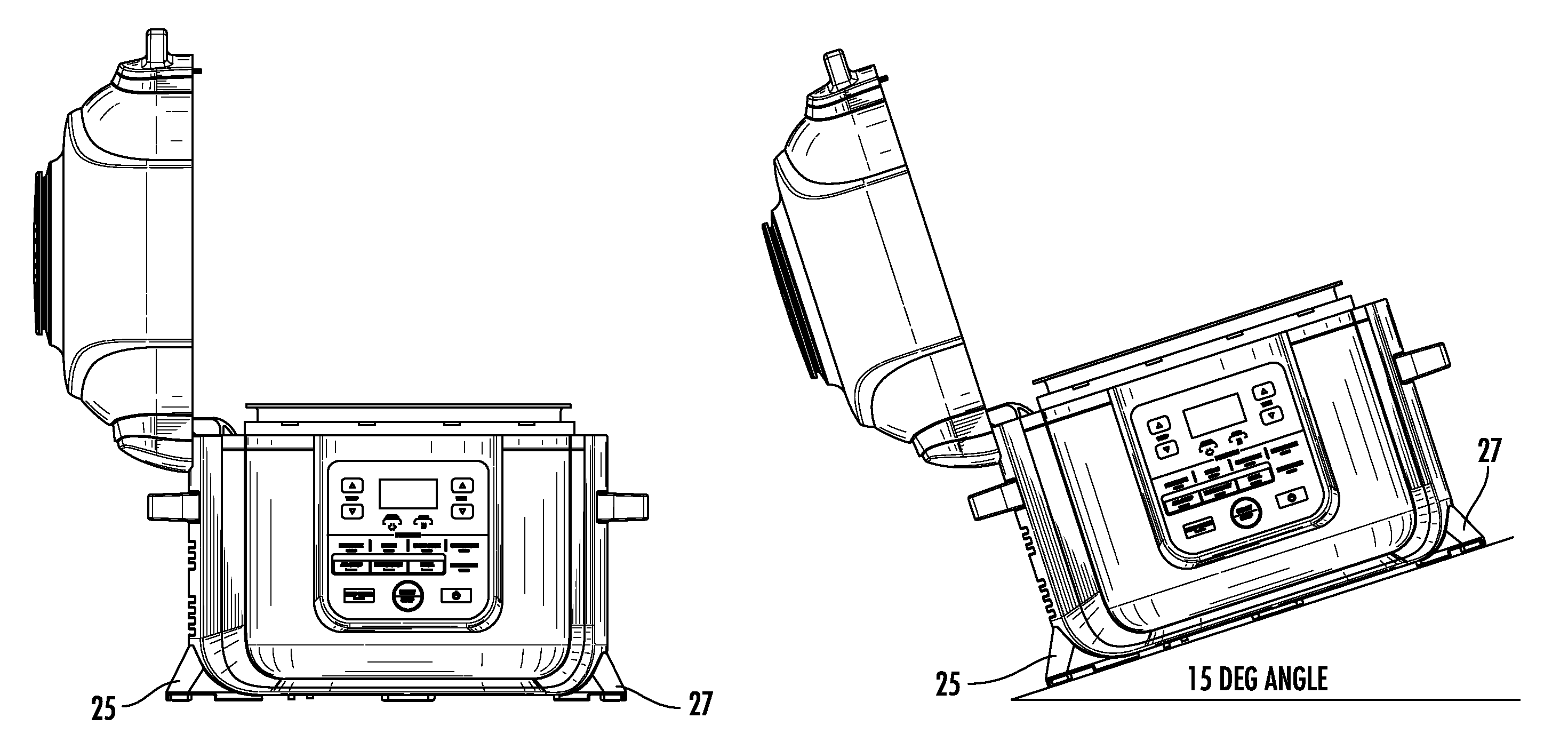
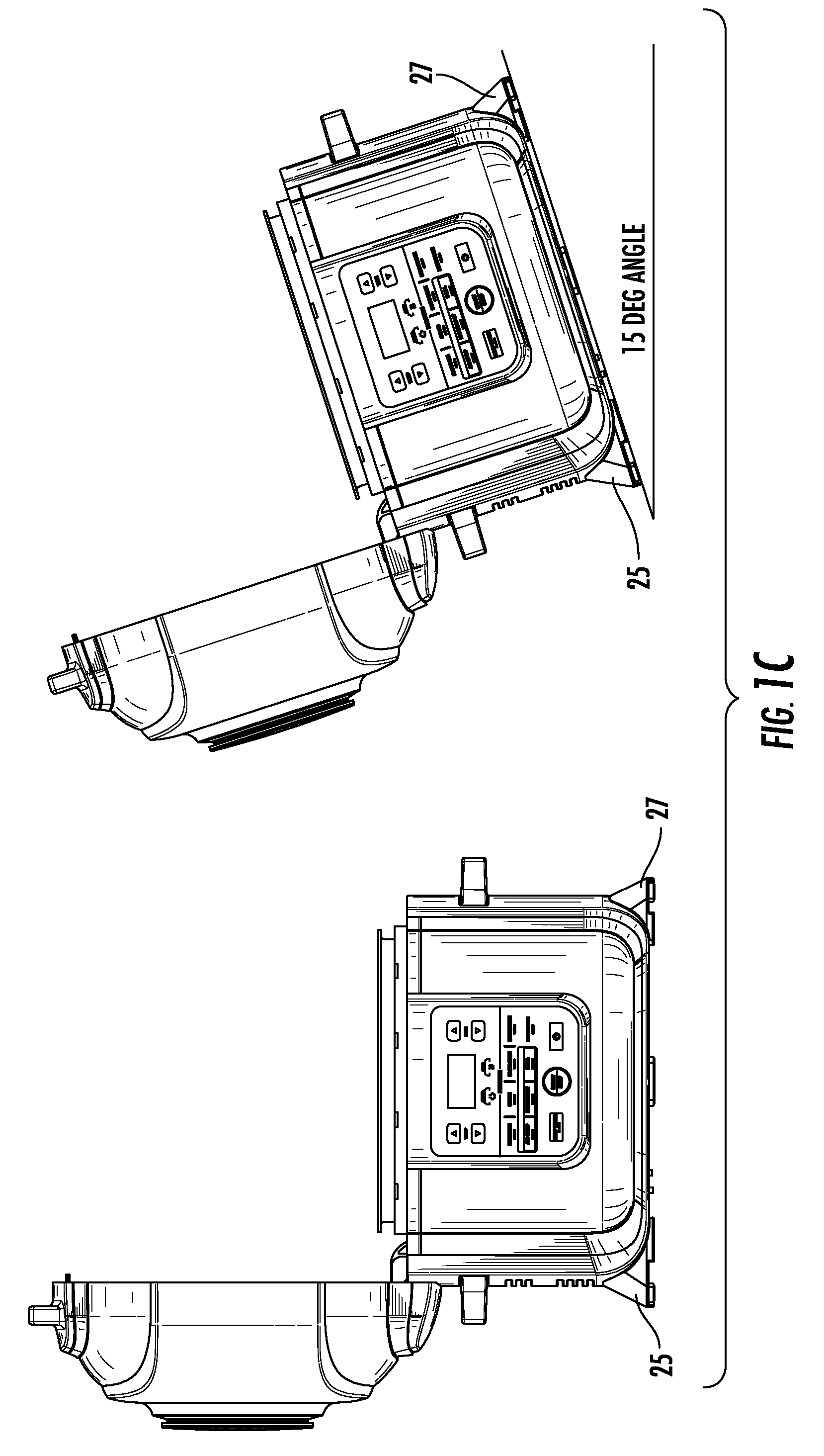
Disclosed herein is a cooking system for cooking food, the system including a housing defining a hollow chamber configured to receive a food container. The housing has an upper portion defining an opening to the hollow chamber. A lid is movably attached to the housing. The lid is moveable about a hinged axis between an open position and a closed position. A foot for supporting the housing is substantially vertically aligned with the hinge axis to stabilize the housing when the housing is oriented at a 15 degree angle and the lid is in the open position.
| Inventors: | Gill; Aaron Michael (Boston, MA), Richardson; Ross (Dover, MA), Zabel; Naomi Kalia Williams (Oakland, CA), Deng; Da (Newton, MA), Gursel; Mete (Istanbul, TR), Tattersfield; Andrew John Roy (London, GB), Denham; Niall Christopher (London, GB), Jackson; Roger Neil (Cornwall, GB), Leahy; Ronan Patrick (London, GB), White; Evan James (Brookline, MA), Guerin; Thomas (Boston, MA), Martin; Chris (Concord, MA), Lavins; Nathaniel R. (Somerville, MA), Swanhart; Mackenzie Lee (Boston, MA), Ferguson; Samuel Andrew (Medford, MA), Stewart; Scott James (Boston, MA) | ||||||||||
|---|---|---|---|---|---|---|---|---|---|---|---|
| Applicant: |
|
||||||||||
| Assignee: | SHARKNINJA OPERATING LLC
(Needham, MA) |
||||||||||
| Family ID: | 63371815 | ||||||||||
| Appl. No.: | 16/357,274 | ||||||||||
| Filed: | March 18, 2019 |
Prior Publication Data
| Document Identifier | Publication Date | |
|---|---|---|
| US 20190231138 A1 | Aug 1, 2019 | |
Related U.S. Patent Documents
| Application Number | Filing Date | Patent Number | Issue Date | ||
|---|---|---|---|---|---|
| 16059876 | Aug 9, 2018 | ||||
| 62543082 | Aug 9, 2017 | ||||
| Current U.S. Class: | 1/1 |
| Current CPC Class: | A47J 37/0641 (20130101); A47J 27/04 (20130101); A47J 27/08 (20130101); A47J 43/0772 (20130101); A47J 27/0802 (20130101); A47J 39/003 (20130101); A47J 37/0623 (20130101); A47J 36/12 (20130101); A47J 37/1266 (20130101) |
| Current International Class: | A47J 27/08 (20060101); A47J 37/06 (20060101); A47J 27/04 (20060101); A47J 36/06 (20060101); A47J 36/12 (20060101); A47J 37/12 (20060101) |
References Cited [Referenced By]
U.S. Patent Documents
| 2055972 | September 1934 | Fritsche |
| 1986088 | January 1935 | Wild |
| 2313968 | October 1937 | Reich |
| 2378950 | October 1937 | Reich |
| 2188757 | August 1938 | Moon |
| 2253833 | December 1939 | Volks |
| 3076405 | February 1963 | Lang |
| 3122134 | February 1964 | Reeves |
| 3514301 | May 1970 | Berger |
| 3529582 | September 1970 | Hurko et al. |
| 3610885 | October 1971 | Zingg |
| 3821454 | June 1974 | Lobel |
| 3828760 | August 1974 | Farber et al. |
| 4106486 | August 1978 | Lee |
| 4148250 | April 1979 | Miki et al. |
| 4162741 | July 1979 | Walker et al. |
| 4210072 | July 1980 | Pedrini |
| 4241288 | December 1980 | Aoshima |
| 4268741 | May 1981 | O'Brien |
| 4374318 | February 1983 | Gilliom |
| 4484063 | November 1984 | Whittenburg et al. |
| 4509412 | April 1985 | Whittenburg et al. |
| 4591698 | May 1986 | Chang |
| 4728762 | March 1988 | Roth et al. |
| 4771162 | September 1988 | Schatz |
| 4848217 | July 1989 | Koziol |
| 4889972 | December 1989 | Chang |
| 5000085 | March 1991 | Archer |
| 5012071 | April 1991 | Henke |
| 5029519 | July 1991 | Boyen |
| 5031519 | July 1991 | Toida et al. |
| 5036179 | July 1991 | Westerberg et al. |
| 5048400 | September 1991 | Ueda et al. |
| 5092229 | March 1992 | Chen |
| 5105725 | April 1992 | Haglund |
| 5205274 | April 1993 | Smith et al. |
| 5251542 | October 1993 | Itoh |
| 5355777 | October 1994 | Chen et al. |
| 5416950 | May 1995 | Dornbush et al. |
| 5445061 | August 1995 | Barradas |
| 5485780 | January 1996 | Koether et al. |
| 5513558 | May 1996 | Erickson et al. |
| 5526734 | June 1996 | Harrison |
| 5549039 | August 1996 | Ito et al. |
| 5567458 | October 1996 | Wu |
| 5588352 | December 1996 | Harrison |
| 5590583 | January 1997 | Harrison |
| 5615607 | April 1997 | Delaquis et al. |
| 5619983 | April 1997 | Smith |
| 5632403 | May 1997 | Deng |
| 5649476 | July 1997 | Montagnino et al. |
| 5676044 | October 1997 | Lara, Jr. |
| 5699722 | December 1997 | Erickson et al. |
| 5740721 | April 1998 | Bizard et al. |
| 5768976 | June 1998 | Suk |
| 5839357 | November 1998 | Ha et al. |
| 5896808 | April 1999 | Graur |
| 5932130 | August 1999 | Taino |
| 5967021 | October 1999 | Yung |
| 6006939 | December 1999 | Wai |
| 6014986 | January 2000 | Baumgarten |
| 6019029 | February 2000 | Chan |
| 6023050 | February 2000 | Violi |
| 6060698 | May 2000 | Petrides et al. |
| 6066837 | May 2000 | McCormick et al. |
| 6067896 | May 2000 | Elorza |
| 6070518 | June 2000 | Kao |
| 6082249 | July 2000 | Su |
| 6083543 | July 2000 | Kim et al. |
| 6097016 | August 2000 | Hirata et al. |
| 6104004 | August 2000 | Ragland et al. |
| 6105808 | August 2000 | Mendonca |
| 6116151 | September 2000 | Fickert et al. |
| 6125737 | October 2000 | Chang |
| 6135012 | October 2000 | Kao |
| 6135013 | October 2000 | Barrena |
| 6158606 | December 2000 | Oliver |
| 6173643 | January 2001 | Qian et al. |
| 6178876 | January 2001 | Kao |
| 6191393 | February 2001 | Park |
| 6201217 | March 2001 | Moon et al. |
| 6242025 | June 2001 | Lesky et al. |
| 6252206 | June 2001 | Leukhardt, III et al. |
| 6255630 | July 2001 | Barnes et al. |
| 6257124 | July 2001 | Chen |
| 6262396 | July 2001 | Witt et al. |
| 6267046 | July 2001 | Wanat |
| 6268592 | July 2001 | Hu et al. |
| 6269737 | August 2001 | Rigney et al. |
| 6271504 | August 2001 | Barritt |
| 6283014 | September 2001 | Ng et al. |
| 6283015 | September 2001 | Kwon et al. |
| 6320166 | November 2001 | Park |
| 6355914 | March 2002 | Stockley |
| 6384381 | May 2002 | Witt et al. |
| D458078 | June 2002 | Lin |
| 6399925 | June 2002 | Pickering et al. |
| 6414254 | July 2002 | McNair |
| 6425320 | July 2002 | Chameroy et al. |
| 6450085 | September 2002 | Riesselman |
| 6450361 | September 2002 | Mendelson et al. |
| 6455085 | September 2002 | Duta |
| 6467645 | October 2002 | Park |
| 6486453 | November 2002 | Bales et al. |
| 6494337 | December 2002 | Moroni |
| 6509550 | January 2003 | Li |
| 6513420 | February 2003 | Park |
| 6523459 | February 2003 | Chameroy et al. |
| 6528772 | March 2003 | Graves et al. |
| 6540097 | April 2003 | Beck et al. |
| 6545252 | April 2003 | Wang |
| 6552309 | April 2003 | Kish et al. |
| 6559427 | May 2003 | Barnes et al. |
| 6565903 | May 2003 | Ng et al. |
| 6573483 | June 2003 | Decobert et al. |
| 6604453 | August 2003 | Niese |
| 6615706 | September 2003 | Wu |
| 6615708 | September 2003 | Lin |
| 6631824 | October 2003 | Park |
| 6669047 | October 2003 | Wooderson et al. |
| 6648162 | November 2003 | Wooderson et al. |
| 6617554 | December 2003 | Moon et al. |
| 6657167 | December 2003 | Loveless |
| 6695319 | February 2004 | Anota et al. |
| D487212 | March 2004 | Park |
| 6698337 | March 2004 | Park |
| 6705209 | March 2004 | Yang et al. |
| 6723963 | April 2004 | Ronda |
| 6730881 | May 2004 | Arntz et al. |
| 6730882 | May 2004 | Atkinson |
| 6730889 | May 2004 | Jones-Lawlor |
| 6736131 | May 2004 | Yamamoto et al. |
| 6740855 | May 2004 | Decobert et al. |
| 6742445 | June 2004 | Backus et al. |
| 6747250 | June 2004 | Cha |
| 6755319 | June 2004 | Park |
| 6758132 | July 2004 | Kuo et al. |
| 6777651 | August 2004 | Boyer |
| 6782805 | August 2004 | Backus et al. |
| 6782806 | August 2004 | Backus et al. |
| 6802429 | October 2004 | Wildman |
| 6809297 | October 2004 | Moon et al. |
| 6812433 | November 2004 | Barritt |
| 6815644 | November 2004 | Muegge et al. |
| 6831254 | December 2004 | Barritt |
| 6837150 | January 2005 | Backus et al. |
| 6841762 | January 2005 | Suzuki |
| 6845707 | January 2005 | Xu et al. |
| 6851351 | February 2005 | Payen et al. |
| 6872921 | March 2005 | Decobert et al. |
| 6874408 | April 2005 | Backus et al. |
| 6877633 | April 2005 | Niese |
| 6903310 | June 2005 | Lee |
| 6917017 | July 2005 | Moon et al. |
| 6933477 | August 2005 | Becker et al. |
| 6935223 | August 2005 | Kobayashi |
| 6936795 | August 2005 | Moon et al. |
| 6936801 | August 2005 | Head |
| 6941857 | September 2005 | McLemore |
| 7009147 | March 2006 | Schulte |
| 7012220 | March 2006 | Boyer et al. |
| 7012221 | March 2006 | Li |
| 7021203 | April 2006 | Backus et al. |
| 7021204 | April 2006 | Backus et al. |
| 7053337 | May 2006 | Ragan et al. |
| 7060943 | June 2006 | Hwang |
| 7081601 | July 2006 | Boyer et al. |
| 7082871 | August 2006 | Schultz |
| 7086326 | August 2006 | Yokoyama |
| 7126088 | October 2006 | Horton et al. |
| 7148451 | December 2006 | Miyake et al. |
| 7154069 | December 2006 | Gordon |
| 7156087 | January 2007 | Churchill et al. |
| 7157675 | January 2007 | Imura |
| 7166822 | January 2007 | Chang et al. |
| 7276677 | October 2007 | Shelton |
| 7285751 | October 2007 | Li et al. |
| 7322279 | January 2008 | Cartigny et al. |
| 7322280 | January 2008 | Seurat Guiochet et al. |
| 7325481 | February 2008 | Helm |
| 7368688 | May 2008 | Kim et al. |
| 7373874 | May 2008 | Seurat Guiochet et al. |
| 7377208 | May 2008 | Ho et al. |
| 7411159 | August 2008 | Oosterling |
| 7412922 | August 2008 | McLemore |
| 7451691 | November 2008 | Robertson |
| 7451692 | November 2008 | Baraille et al. |
| 7468495 | December 2008 | Carbone et al. |
| 7523696 | April 2009 | Seurat Guiochet et al. |
| 7530302 | May 2009 | Stephanou |
| 7565862 | July 2009 | Cartigny et al. |
| 7605349 | October 2009 | Gaynor et al. |
| D604098 | November 2009 | Hamlin |
| 7619186 | November 2009 | Cavada et al. |
| 7624674 | December 2009 | Chameroy et al. |
| 7637206 | December 2009 | Seurat Guiochet et al. |
| 7669521 | March 2010 | Cartigny et al. |
| 7703385 | April 2010 | Seurat Guiochet et al. |
| 7718928 | May 2010 | He et al. |
| 7726508 | June 2010 | Hasegawa |
| 7762420 | July 2010 | Auwarter et al. |
| 7766003 | August 2010 | Kim |
| 7775390 | August 2010 | De Bastos Reis Portugal et al. |
| 7800022 | September 2010 | Kim |
| 7838799 | November 2010 | Freedman |
| 7875836 | January 2011 | Imura et al. |
| 7935914 | May 2011 | Imura |
| 7964824 | June 2011 | Moon |
| 7968824 | June 2011 | Lee et al. |
| 8006685 | August 2011 | Bolton et al. |
| 8011293 | September 2011 | McFadden et al. |
| 8096436 | January 2012 | Rhetat et al. |
| 8096440 | January 2012 | Rhetat et al. |
| 8205543 | June 2012 | Rhetat et al. |
| 8247751 | August 2012 | Jagannathan |
| 8258435 | September 2012 | Bonuso et al. |
| D669730 | October 2012 | Mandil |
| 8276507 | October 2012 | Walker |
| 8286548 | October 2012 | Krishnan et al. |
| 8299404 | October 2012 | Van Der Weij |
| 8302800 | November 2012 | Hasegawa |
| 8304695 | November 2012 | Bonuso et al. |
| 8330083 | December 2012 | Moon et al. |
| 8338757 | December 2012 | Isoda et al. |
| 8378265 | February 2013 | Greenwood et al. |
| 8381712 | February 2013 | Simms, II |
| 8393262 | March 2013 | Molayem |
| 8461488 | June 2013 | Jeong et al. |
| 8517205 | August 2013 | Thelen |
| 8544381 | October 2013 | Cartigny et al. |
| 8546731 | October 2013 | Pellerin et al. |
| 8561525 | October 2013 | Bauchot et al. |
| 8578293 | November 2013 | Breunig et al. |
| 8581137 | November 2013 | Egenter |
| 8618447 | December 2013 | De'Longhi |
| 8637797 | January 2014 | Imura |
| D699514 | February 2014 | Lovley, II et al. |
| 8640908 | February 2014 | Yang et al. |
| 8674270 | March 2014 | Anderson et al. |
| 8689680 | April 2014 | Park |
| 8709905 | April 2014 | Crayfourd |
| 8714391 | May 2014 | Milanesi |
| 8726792 | May 2014 | Shealy et al. |
| 8733574 | May 2014 | Heidrich et al. |
| D707078 | June 2014 | Rivera et al. |
| 8739690 | June 2014 | Chameroy et al. |
| 8747933 | June 2014 | McGinn |
| 8766144 | July 2014 | McLoughlin et al. |
| 8777038 | July 2014 | Wen |
| 8783498 | July 2014 | Li |
| 8783947 | July 2014 | Ferron et al. |
| D710647 | August 2014 | Mandil et al. |
| 8800803 | August 2014 | Stellwag |
| 8808772 | August 2014 | Lubrina et al. |
| 8813989 | August 2014 | Hoffmann et al. |
| 8820220 | September 2014 | Thelen et al. |
| 8847129 | September 2014 | Kim et al. |
| 8869829 | October 2014 | Hasegawa |
| 8887939 | November 2014 | Chameroy et al. |
| D719398 | December 2014 | Deters |
| D720571 | January 2015 | Deters |
| 8931402 | January 2015 | Chameroy et al. |
| 8931659 | January 2015 | Rhetat et al. |
| 8944272 | February 2015 | Chameroy et al. |
| 8944273 | February 2015 | Chameroy et al. |
| 8973770 | March 2015 | He et al. |
| 8985372 | March 2015 | Yang et al. |
| 8991307 | March 2015 | Grozinger et al. |
| D727095 | April 2015 | Bak |
| 9018566 | April 2015 | Wang |
| 9027468 | May 2015 | Rhetat et al. |
| 9035223 | May 2015 | Noguchi et al. |
| 9055618 | June 2015 | Bunzel et al. |
| 9057526 | June 2015 | Barritt |
| 9119501 | September 2015 | Xie |
| 9125513 | September 2015 | Kim |
| 9138106 | September 2015 | Walker |
| 9177460 | November 2015 | Fissler |
| 9191998 | November 2015 | Hegedis et al. |
| 9220362 | December 2015 | Eades et al. |
| 9237829 | January 2016 | Alet Vidal et al. |
| D749906 | February 2016 | Lee |
| 9271595 | March 2016 | Lee |
| 9295354 | March 2016 | Sloot et al. |
| D754469 | April 2016 | Deters |
| 9301644 | April 2016 | Payen et al. |
| 9314134 | April 2016 | Molnar |
| 9320381 | April 2016 | Chameroy et al. |
| 9339145 | May 2016 | Owczarzak |
| 9341382 | May 2016 | Kim |
| 9351495 | May 2016 | McFadden |
| 9353954 | May 2016 | Linnewiel |
| 9414713 | August 2016 | Jinzhao |
| 9433036 | August 2016 | Kurtimoto et al. |
| 9439530 | September 2016 | Logan et al. |
| D769058 | October 2016 | Lee |
| 9456713 | October 2016 | Backaert et al. |
| 9470423 | October 2016 | Jacob et al. |
| 9474412 | October 2016 | Fung et al. |
| D772648 | November 2016 | Palermo |
| 9480364 | November 2016 | McKee et al. |
| D774350 | December 2016 | Mandil |
| D774356 | December 2016 | Maiorana et al. |
| 9526367 | December 2016 | Anota et al. |
| 9585509 | March 2017 | Wassmus et al. |
| 9596954 | March 2017 | Park |
| 9615691 | April 2017 | Xiao |
| 9615692 | April 2017 | Hoffmann et al. |
| 9615694 | April 2017 | Yoshidome |
| 9629499 | April 2017 | Kim |
| 9629500 | April 2017 | Chance |
| 9636618 | May 2017 | Fung et al. |
| 9642487 | May 2017 | McGinn |
| 9648975 | May 2017 | Imura |
| 9648985 | May 2017 | Huang et al. |
| 9681770 | June 2017 | Backaert et al. |
| 9681773 | June 2017 | McKee et al. |
| 9706871 | July 2017 | Matthijs |
| 9717364 | August 2017 | Sladecek |
| 9737936 | August 2017 | Linglin et al. |
| 9750089 | August 2017 | Wiedemann et al. |
| 9756980 | September 2017 | Li et al. |
| 9763531 | September 2017 | Baraille et al. |
| D801106 | October 2017 | Mirchandani et al. |
| 9775461 | October 2017 | Yang et al. |
| 9795250 | October 2017 | Huang |
| 9801491 | October 2017 | Cohade et al. |
| 9814355 | November 2017 | Winter et al. |
| 9841261 | December 2017 | Raghavan et al. |
| 9854932 | January 2018 | Tiruvallur |
| 9854941 | January 2018 | Bonaccorso |
| 9861231 | January 2018 | Kim |
| 9867234 | January 2018 | Thomann et al. |
| 9872582 | January 2018 | Song et al. |
| 9877610 | January 2018 | Bucher et al. |
| 9883768 | February 2018 | Starflinger |
| 9888811 | February 2018 | Zwanenburg et al. |
| 9895028 | February 2018 | Gerard et al. |
| 9900936 | February 2018 | Imm et al. |
| 9909764 | March 2018 | Bach |
| 9924830 | March 2018 | Glucksman et al. |
| D815491 | April 2018 | Hollinger |
| 9930990 | April 2018 | Gupta et al. |
| D817697 | May 2018 | Zhao |
| 9961721 | May 2018 | Guilleminot et al. |
| 9962029 | May 2018 | Baraille et al. |
| 9980605 | May 2018 | De Haas et al. |
| 10016085 | July 2018 | Sapire |
| 10021889 | July 2018 | Vinett |
| 10034578 | July 2018 | Ahmed |
| D824717 | August 2018 | Allen |
| D826638 | August 2018 | Zhang |
| 10045651 | August 2018 | Huang |
| 10051986 | August 2018 | Schultz et al. |
| 10051995 | August 2018 | Buckley et al. |
| 10057946 | August 2018 | Mills et al. |
| 10058210 | August 2018 | Palermo |
| 10060632 | August 2018 | Lim et al. |
| 10064518 | September 2018 | Xiao et al. |
| 10076206 | September 2018 | Chameroy et al. |
| D832023 | October 2018 | Barberi et al. |
| D832030 | October 2018 | Veldeman |
| 10088371 | October 2018 | Kaiser et al. |
| D833204 | November 2018 | Lee |
| 10117546 | November 2018 | Le Grand |
| 10123656 | November 2018 | Shanmugam |
| 10130205 | November 2018 | Fung et al. |
| D834889 | December 2018 | Moon et al. |
| 10154750 | December 2018 | Allemand et al. |
| D838548 | January 2019 | Schutte |
| D842649 | March 2019 | Mishan |
| 10231565 | March 2019 | Song et al. |
| 10244883 | April 2019 | Chameroy et al. |
| 2002/0179587 | December 2002 | Hui |
| 2002/0185012 | December 2002 | Yokoyama |
| 2003/0034027 | February 2003 | Yamamoto et al. |
| 2003/0127447 | July 2003 | Lin |
| 2004/0035845 | February 2004 | Moon et al. |
| 2004/0045446 | March 2004 | Park |
| 2004/0055474 | March 2004 | Lekic et al. |
| 2004/0124197 | July 2004 | Hasegawa |
| 2004/0222208 | November 2004 | Ko |
| 2005/0011370 | January 2005 | Xu et al. |
| 2005/0034716 | February 2005 | Harbin |
| 2005/0089318 | April 2005 | Lai et al. |
| 2005/0223906 | October 2005 | Xu |
| 2005/0284305 | December 2005 | Angue |
| 2006/0081235 | April 2006 | Lundh et al. |
| 2007/0045284 | March 2007 | Balk et al. |
| 2007/0095215 | May 2007 | Ho et al. |
| 2007/0125768 | June 2007 | Kim et al. |
| 2007/0158335 | July 2007 | Mansbery |
| 2007/0199557 | August 2007 | Von Kaenel, Jr. |
| 2007/0295221 | December 2007 | Seurat Guiochet et al. |
| 2008/0022861 | January 2008 | Ferron |
| 2008/0078371 | April 2008 | Boscaino |
| 2008/0078755 | April 2008 | Jeon et al. |
| 2008/0083730 | April 2008 | Dolgov et al. |
| 2008/0095905 | April 2008 | Sells et al. |
| 2008/0099008 | May 2008 | Bolton et al. |
| 2008/0105137 | May 2008 | Genslak et al. |
| 2008/0142498 | June 2008 | He et al. |
| 2008/0163764 | July 2008 | Payen et al. |
| 2008/0206420 | August 2008 | McFadden |
| 2008/0213447 | September 2008 | Payen et al. |
| 2008/0223224 | September 2008 | Martin |
| 2008/0290090 | November 2008 | Kindler et al. |
| 2008/0314258 | December 2008 | Martin |
| 2009/0011101 | January 2009 | Doherty et al. |
| 2009/0013988 | January 2009 | Kim et al. |
| 2009/0064868 | March 2009 | Cartossi |
| 2009/0095166 | April 2009 | Jian |
| 2009/0134140 | May 2009 | Vern Der Weij |
| 2009/0223380 | September 2009 | Van Aken |
| 2009/0223386 | September 2009 | Edwards |
| 2009/0250452 | October 2009 | Tse |
| 2010/0089248 | April 2010 | Jones |
| 2010/0136194 | June 2010 | Schutte |
| 2010/0147159 | June 2010 | Fossati |
| 2010/0147824 | June 2010 | Bonuso et al. |
| 2010/0206289 | August 2010 | Larsen et al. |
| 2010/0282097 | November 2010 | Schulte |
| 2011/0003048 | January 2011 | Sugimoto et al. |
| 2011/0095015 | April 2011 | Kao |
| 2011/0168158 | April 2011 | Barkhouse |
| 2011/0120319 | May 2011 | Chang |
| 2011/0126719 | June 2011 | Valance |
| 2011/0146653 | June 2011 | Kitatani |
| 2011/0147376 | June 2011 | Ueda et al. |
| 2011/0248020 | October 2011 | Yuan |
| 2011/0268153 | November 2011 | He et al. |
| 2012/0003364 | January 2012 | Kling et al. |
| 2012/0009317 | January 2012 | McLemore |
| 2012/0012584 | January 2012 | Chameroy et al. |
| 2012/0024164 | February 2012 | Park et al. |
| 2012/0024169 | February 2012 | Hsu |
| 2012/0040067 | February 2012 | Baraille et al. |
| 2012/0048843 | March 2012 | Feng et al. |
| 2012/0125313 | May 2012 | Van Der Weij |
| 2012/0174797 | July 2012 | Froza |
| 2012/0181363 | July 2012 | Huang |
| 2012/0192726 | August 2012 | Clearman et al. |
| 2012/0217236 | August 2012 | Takagi |
| 2012/0217252 | August 2012 | Jung |
| 2012/0222665 | September 2012 | Ahmed |
| 2012/0318149 | December 2012 | Ahmed |
| 2013/0019759 | January 2013 | Tumenbatur et al. |
| 2013/0074702 | March 2013 | Difante |
| 2013/0092145 | April 2013 | Murphy et al. |
| 2013/0104875 | May 2013 | Schultz et al. |
| 2013/0180413 | July 2013 | Tjerkgaast et al. |
| 2013/0180986 | July 2013 | He et al. |
| 2013/0196038 | August 2013 | Liu |
| 2013/0255509 | October 2013 | He et al. |
| 2013/0276643 | October 2013 | Krolick et al. |
| 2013/0298781 | November 2013 | Ganuza et al. |
| 2013/0305933 | November 2013 | Heidrich et al. |
| 2013/0333685 | December 2013 | Jeong et al. |
| 2014/0021191 | January 2014 | Moon et al. |
| 2014/0083306 | March 2014 | Lee |
| 2014/0083992 | March 2014 | Linnewiel |
| 2014/0102315 | April 2014 | Park |
| 2014/0157994 | June 2014 | Ryan et al. |
| 2014/0175085 | June 2014 | Yang et al. |
| 2014/0199459 | July 2014 | Jackson et al. |
| 2014/0201688 | July 2014 | Guilleminot et al. |
| 2014/0220196 | August 2014 | Veloo |
| 2014/0227411 | August 2014 | Popeil |
| 2014/0245898 | September 2014 | Froza |
| 2014/0251158 | September 2014 | Yang et al. |
| 2014/0318385 | October 2014 | Kim |
| 2014/0318386 | October 2014 | Kim |
| 2014/0318387 | October 2014 | Kim |
| 2014/0318388 | October 2014 | Kim |
| 2014/0318389 | October 2014 | Kim |
| 2014/0322417 | October 2014 | Kim |
| 2014/0348987 | November 2014 | Cheng et al. |
| 2014/0353316 | December 2014 | Lin |
| 2014/0360384 | December 2014 | Kim |
| 2014/0366746 | December 2014 | Tsai |
| 2014/0370176 | December 2014 | Imura et al. |
| 2014/0377417 | December 2014 | Martinez |
| 2015/0000535 | January 2015 | Yoshidome et al. |
| 2015/0083107 | March 2015 | Busch et al. |
| 2015/0122137 | May 2015 | Chang |
| 2015/0136769 | May 2015 | Quinn et al. |
| 2015/0201788 | July 2015 | Douma et al. |
| 2015/0201806 | July 2015 | Yoshidome |
| 2015/0208845 | July 2015 | Robbins et al. |
| 2015/0208858 | July 2015 | Robbins et al. |
| 2015/0223627 | August 2015 | Li et al. |
| 2015/0226438 | August 2015 | Ozyurt et al. |
| 2015/0250187 | September 2015 | Sakane et al. |
| 2015/0292750 | October 2015 | Delrue et al. |
| 2015/0305093 | October 2015 | Smith et al. |
| 2015/0313399 | November 2015 | Park |
| 2015/0351578 | December 2015 | Song et al. |
| 2015/0366402 | December 2015 | Wu et al. |
| 2016/0007644 | January 2016 | Hack et al. |
| 2016/0007789 | January 2016 | Tiruvallur |
| 2016/0029829 | February 2016 | Klein |
| 2016/0033141 | February 2016 | Rizzuto |
| 2016/0037955 | February 2016 | Kim |
| 2016/0045067 | February 2016 | Liao |
| 2016/0051077 | February 2016 | Sloot et al. |
| 2016/0051078 | February 2016 | Jenkins et al. |
| 2016/0051086 | February 2016 | De Longhi |
| 2016/0081509 | March 2016 | Delrue et al. |
| 2016/0100707 | April 2016 | Huang |
| 2016/0100713 | April 2016 | De Haas et al. |
| 2016/0113442 | April 2016 | De Haas et al. |
| 2016/0120363 | May 2016 | Zwanenburg et al. |
| 2016/0120364 | May 2016 | De Haas et al. |
| 2016/0123660 | May 2016 | Peng |
| 2016/0165676 | June 2016 | Imm et al. |
| 2016/0174749 | June 2016 | Eades et al. |
| 2016/0174764 | June 2016 | Xiao |
| 2016/0174771 | June 2016 | Benoit et al. |
| 2016/0183722 | June 2016 | Fisher |
| 2016/0206139 | June 2016 | Johnson |
| 2016/0206140 | June 2016 | Johnson et al. |
| 2016/0192808 | July 2016 | Van Der Burg et al. |
| 2016/0198882 | July 2016 | Linglin |
| 2016/0198883 | July 2016 | Wang et al. |
| 2016/0206131 | July 2016 | Chien |
| 2016/0219653 | July 2016 | Kim et al. |
| 2016/0220057 | August 2016 | Smith et al. |
| 2016/0235078 | August 2016 | Farina et al. |
| 2016/0235239 | August 2016 | Patadia |
| 2016/0253080 | September 2016 | Ban et al. |
| 2016/0270596 | September 2016 | Allemand et al. |
| 2016/0278563 | September 2016 | Choudhary |
| 2016/0278565 | September 2016 | Chameroy et al. |
| 2016/0281994 | September 2016 | Nuessler |
| 2016/0309956 | October 2016 | Glucksman |
| 2016/0316525 | October 2016 | Vainionpaa |
| 2016/0316968 | November 2016 | Linglin |
| 2016/0324359 | November 2016 | Aboujassoum et al. |
| 2016/0327280 | November 2016 | Smith et al. |
| 2016/0345766 | December 2016 | Sapire |
| 2016/0353913 | December 2016 | Chameroy et al. |
| 2016/0353914 | December 2016 | Chameroy et al. |
| 2016/0353915 | December 2016 | Chameroy et al. |
| 2016/0353916 | December 2016 | Chameroy et al. |
| 2016/0360922 | December 2016 | Xiao et al. |
| 2016/0367061 | December 2016 | Chou |
| 2016/0374510 | December 2016 | Albizuri Landazabal |
| 2017/0000293 | January 2017 | Sladecek et al. |
| 2017/0020334 | January 2017 | Sorenson et al. |
| 2017/0055770 | March 2017 | Case |
| 2017/0065127 | March 2017 | Bonaccorso |
| 2017/0071034 | March 2017 | Metz |
| 2017/0079475 | March 2017 | Buckley et al. |
| 2017/0089590 | March 2017 | Bruin-Slot et al. |
| 2017/0099977 | April 2017 | Liu |
| 2017/0099984 | April 2017 | Koetz |
| 2017/0099990 | April 2017 | Magnouloux et al. |
| 2017/0099995 | April 2017 | Magnouloux |
| 2017/0119192 | May 2017 | Sanserverino |
| 2017/0172335 | June 2017 | Colas et al. |
| 2017/0181564 | June 2017 | He et al. |
| 2017/0199658 | July 2017 | Stoufer et al. |
| 2017/0231415 | August 2017 | Cheng et al. |
| 2017/0231430 | August 2017 | Moon et al. |
| 2017/0245674 | August 2017 | Imura |
| 2017/0245683 | August 2017 | Chen et al. |
| 2017/0245686 | August 2017 | Man |
| 2017/0251872 | September 2017 | Li et al. |
| 2017/0251874 | September 2017 | Sladecek |
| 2017/0280914 | October 2017 | Kumar et al. |
| 2017/0290452 | October 2017 | Guillaume et al. |
| 2017/0295993 | October 2017 | Li et al. |
| 2017/0303740 | October 2017 | Bonaccorso |
| 2017/0332823 | November 2017 | Sanseverino |
| 2017/0360238 | December 2017 | Bogazzi |
| 2017/0360254 | December 2017 | Muhr et al. |
| 2017/0360255 | December 2017 | Karau |
| 2017/0367514 | December 2017 | In 'T Groen et al. |
| 2017/0370595 | December 2017 | Yang et al. |
| 2018/0000285 | January 2018 | Backus et al. |
| 2018/0007744 | January 2018 | Nonaka et al. |
| 2018/0028017 | February 2018 | Wu |
| 2018/0035698 | February 2018 | McNerney et al. |
| 2018/0073739 | March 2018 | Dumenil |
| 2018/0078089 | March 2018 | Sauer et al. |
| 2018/0103796 | April 2018 | Park |
| 2018/0110355 | April 2018 | Huang et al. |
| 2018/0116264 | May 2018 | De Winter et al. |
| 2018/0116438 | May 2018 | He et al. |
| 2018/0125293 | May 2018 | McNerney et al. |
| 2018/0125294 | May 2018 | Conte et al. |
| 2018/0140126 | May 2018 | Van Dillen |
| 2018/0143086 | May 2018 | Stoufer et al. |
| 2018/0153329 | June 2018 | Glucksman et al. |
| 2018/0160840 | June 2018 | De' Longhi |
| 2018/0160849 | June 2018 | Hebert, Jr. et al. |
| 2018/0177322 | June 2018 | Kim |
| 2018/0177343 | June 2018 | Bonaccorso |
| 2018/0184843 | July 2018 | Kim et al. |
| 2018/0184848 | July 2018 | De' Longhi |
| 2018/0192825 | July 2018 | Popeil et al. |
| 2018/0199756 | July 2018 | Huang |
| 2018/0206672 | July 2018 | Grace et al. |
| 2018/0206677 | July 2018 | Ivarsson et al. |
| 2018/0220498 | August 2018 | Jeon et al. |
| 2018/0220842 | August 2018 | Delrue et al. |
| 2018/0228318 | August 2018 | Zwanenburg et al. |
| 2018/0238560 | August 2018 | Deng et al. |
| 2018/0255967 | September 2018 | Haas et al. |
| 2018/0255971 | September 2018 | Moon et al. |
| 2018/0263084 | September 2018 | Yoshino et al. |
| 2018/0266697 | September 2018 | Dash et al. |
| 2018/0271321 | September 2018 | Delrue et al. |
| 2018/0271323 | September 2018 | Zhang et al. |
| 2018/0279832 | October 2018 | Ohta et al. |
| 2018/0289212 | October 2018 | Sladecek et al. |
| 2018/0296019 | October 2018 | Kim et al. |
| 2018/0303285 | October 2018 | Cheng |
| 2018/0317691 | November 2018 | Huang |
| 2018/0317692 | November 2018 | Huang |
| 2018/0317693 | November 2018 | Huang |
| 2018/0325313 | November 2018 | De'Longhi et al. |
| 2018/0325318 | November 2018 | De Longhi et al. |
| 2018/0325322 | November 2018 | De'Longhi et al. |
| 2018/0333004 | November 2018 | Delonghi |
| 2018/0333005 | November 2018 | Fritz et al. |
| 2018/0344085 | December 2018 | Dutter |
| 2018/0347829 | December 2018 | Martini et al. |
| 2018/0353007 | December 2018 | Eberhart et al. |
| 2018/0353010 | December 2018 | Delrue et al. |
| 2018/0359823 | December 2018 | Shin et al. |
| 2019/0000267 | January 2019 | Li et al. |
| 2019/0008316 | January 2019 | Kim et al. |
| 2019/0021142 | January 2019 | Mizuta et al. |
| 2019/0045964 | February 2019 | Gill et al. |
| 2019/0045973 | February 2019 | Gill et al. |
| 2019/0053521 | February 2019 | Tian et al. |
| 2019/0059647 | February 2019 | Floessholzer |
| 2019/0069719 | March 2019 | Huang et al. |
| 2019/0082876 | March 2019 | Shi et al. |
| 2253170 | Apr 1997 | CN | |||
| 1218653 | Jun 1999 | CN | |||
| 2389593 | Aug 2000 | CN | |||
| 2450993 | Oct 2001 | CN | |||
| 2469839 | Jan 2002 | CN | |||
| 2479871 | Mar 2002 | CN | |||
| 1139352 | Feb 2004 | CN | |||
| 1148142 | May 2004 | CN | |||
| 1158963 | Jul 2004 | CN | |||
| 2719176 | Aug 2005 | CN | |||
| 1883351 | Dec 2006 | CN | |||
| 2855256 | Jan 2007 | CN | |||
| 2904903 | May 2007 | CN | |||
| 1981682 | Jun 2007 | CN | |||
| 1985727 | Jun 2007 | CN | |||
| 1989884 | Jul 2007 | CN | |||
| 100998476 | Jul 2007 | CN | |||
| 101023842 | Aug 2007 | CN | |||
| 101053485 | Oct 2007 | CN | |||
| 200987595 | Dec 2007 | CN | |||
| 101099635 | Jan 2008 | CN | |||
| 101108064 | Jan 2008 | CN | |||
| 101112291 | Jan 2008 | CN | |||
| 101112292 | Jan 2008 | CN | |||
| 101112293 | Jan 2008 | CN | |||
| 101142448 | Mar 2008 | CN | |||
| 101185556 | May 2008 | CN | |||
| 100401957 | Jul 2008 | CN | |||
| 101209179 | Jul 2008 | CN | |||
| 101209180 | Jul 2008 | CN | |||
| 201079267 | Jul 2008 | CN | |||
| 100425186 | Oct 2008 | CN | |||
| 100428906 | Oct 2008 | CN | |||
| 101273834 | Oct 2008 | CN | |||
| 201139427 | Oct 2008 | CN | |||
| 101322614 | Dec 2008 | CN | |||
| 201197609 | Feb 2009 | CN | |||
| 100464682 | Mar 2009 | CN | |||
| 100469289 | Mar 2009 | CN | |||
| 201207144 | Mar 2009 | CN | |||
| 101432608 | May 2009 | CN | |||
| 101438929 | May 2009 | CN | |||
| 100496350 | Jun 2009 | CN | |||
| 100522018 | Aug 2009 | CN | |||
| 100531628 | Aug 2009 | CN | |||
| 100534363 | Sep 2009 | CN | |||
| 101518409 | Sep 2009 | CN | |||
| 100559999 | Nov 2009 | CN | |||
| 201365839 | Dec 2009 | CN | |||
| 100588351 | Feb 2010 | CN | |||
| 101669761 | Mar 2010 | CN | |||
| 101766443 | Jul 2010 | CN | |||
| 101791190 | Aug 2010 | CN | |||
| 101828856 | Sep 2010 | CN | |||
| 101856086 | Oct 2010 | CN | |||
| 201602600 | Oct 2010 | CN | |||
| 201624512 | Nov 2010 | CN | |||
| 101936550 | Jan 2011 | CN | |||
| 101940273 | Jan 2011 | CN | |||
| 101420893 | Feb 2011 | CN | |||
| 101977536 | Feb 2011 | CN | |||
| 201888709 | Jul 2011 | CN | |||
| 201929758 | Aug 2011 | CN | |||
| 201948771 | Aug 2011 | CN | |||
| 102178445 | Sep 2011 | CN | |||
| 102178464 | Sep 2011 | CN | |||
| 201958652 | Sep 2011 | CN | |||
| 101305890 | Nov 2011 | CN | |||
| 102240164 | Nov 2011 | CN | |||
| 102307500 | Jan 2012 | CN | |||
| 102313306 | Feb 2012 | CN | |||
| 102349791 | Feb 2012 | CN | |||
| 202151310 | Feb 2012 | CN | |||
| 102368936 | Mar 2012 | CN | |||
| 202184614 | Apr 2012 | CN | |||
| 101692958 | May 2012 | CN | |||
| 202207075 | May 2012 | CN | |||
| 202234720 | May 2012 | CN | |||
| 202234761 | May 2012 | CN | |||
| 202312886 | Jul 2012 | CN | |||
| 102670079 | Sep 2012 | CN | |||
| 202408428 | Sep 2012 | CN | |||
| 202408455 | Sep 2012 | CN | |||
| 102755120 | Oct 2012 | CN | |||
| 102824120 | Dec 2012 | CN | |||
| 202619362 | Dec 2012 | CN | |||
| 102100481 | Jan 2013 | CN | |||
| 102883641 | Jan 2013 | CN | |||
| 202636678 | Jan 2013 | CN | |||
| 103006045 | Apr 2013 | CN | |||
| 103006092 | Apr 2013 | CN | |||
| 202858889 | Apr 2013 | CN | |||
| 103142128 | Jun 2013 | CN | |||
| 103142151 | Jun 2013 | CN | |||
| 103169371 | Jun 2013 | CN | |||
| 103179884 | Jun 2013 | CN | |||
| 202960194 | Jun 2013 | CN | |||
| 202981682 | Jun 2013 | CN | |||
| 203000535 | Jun 2013 | CN | |||
| 103188947 | Jul 2013 | CN | |||
| 103188970 | Jul 2013 | CN | |||
| 103220947 | Jul 2013 | CN | |||
| 103222807 | Jul 2013 | CN | |||
| 203041954 | Jul 2013 | CN | |||
| 203041955 | Jul 2013 | CN | |||
| 102342739 | Aug 2013 | CN | |||
| 203122175 | Aug 2013 | CN | |||
| 103299132 | Sep 2013 | CN | |||
| 203195497 | Sep 2013 | CN | |||
| 203195499 | Sep 2013 | CN | |||
| 103375826 | Oct 2013 | CN | |||
| 203234602 | Oct 2013 | CN | |||
| 203234613 | Oct 2013 | CN | |||
| 102319018 | Nov 2013 | CN | |||
| 203302862 | Nov 2013 | CN | |||
| 103445669 | Dec 2013 | CN | |||
| 102397005 | Jan 2014 | CN | |||
| 103491830 | Jan 2014 | CN | |||
| 203407931 | Jan 2014 | CN | |||
| 103649643 | Mar 2014 | CN | |||
| 103750730 | Apr 2014 | CN | |||
| 203539138 | Apr 2014 | CN | |||
| 203597772 | May 2014 | CN | |||
| 203615383 | May 2014 | CN | |||
| 203634023 | Jun 2014 | CN | |||
| 203647141 | Jun 2014 | CN | |||
| 203662545 | Jun 2014 | CN | |||
| 103892696 | Jul 2014 | CN | |||
| 103948308 | Jul 2014 | CN | |||
| 203693372 | Jul 2014 | CN | |||
| 203723888 | Jul 2014 | CN | |||
| 104000478 | Aug 2014 | CN | |||
| 203762926 | Aug 2014 | CN | |||
| 203776718 | Aug 2014 | CN | |||
| 203776719 | Aug 2014 | CN | |||
| 203776729 | Aug 2014 | CN | |||
| 203828675 | Sep 2014 | CN | |||
| 203873602 | Oct 2014 | CN | |||
| 203885286 | Oct 2014 | CN | |||
| 203953373 | Nov 2014 | CN | |||
| 203970073 | Dec 2014 | CN | |||
| 203970160 | Dec 2014 | CN | |||
| 203987492 | Dec 2014 | CN | |||
| 203987520 | Dec 2014 | CN | |||
| 203987550 | Dec 2014 | CN | |||
| 203987551 | Dec 2014 | CN | |||
| 204016055 | Dec 2014 | CN | |||
| 204016056 | Dec 2014 | CN | |||
| 204049362 | Dec 2014 | CN | |||
| 204091768 | Jan 2015 | CN | |||
| 104323708 | Feb 2015 | CN | |||
| 104367182 | Feb 2015 | CN | |||
| 204133165 | Feb 2015 | CN | |||
| 204133291 | Feb 2015 | CN | |||
| 204158183 | Feb 2015 | CN | |||
| 104433841 | Mar 2015 | CN | |||
| 204192406 | Mar 2015 | CN | |||
| 104490294 | Apr 2015 | CN | |||
| 102917623 | May 2015 | CN | |||
| 104613515 | May 2015 | CN | |||
| 104622274 | May 2015 | CN | |||
| 104676681 | Jun 2015 | CN | |||
| 104688019 | Jun 2015 | CN | |||
| 104706212 | Jun 2015 | CN | |||
| 104754992 | Jul 2015 | CN | |||
| 104757872 | Jul 2015 | CN | |||
| 104814665 | Aug 2015 | CN | |||
| 104856561 | Aug 2015 | CN | |||
| 104856563 | Aug 2015 | CN | |||
| 204580991 | Aug 2015 | CN | |||
| 104873098 | Sep 2015 | CN | |||
| 104887063 | Sep 2015 | CN | |||
| 204636063 | Sep 2015 | CN | |||
| 104983318 | Oct 2015 | CN | |||
| 104997394 | Oct 2015 | CN | |||
| 204697804 | Oct 2015 | CN | |||
| 105011741 | Nov 2015 | CN | |||
| 105030035 | Nov 2015 | CN | |||
| 105054772 | Nov 2015 | CN | |||
| 105054773 | Nov 2015 | CN | |||
| 204734374 | Nov 2015 | CN | |||
| 204743846 | Nov 2015 | CN | |||
| 204765197 | Nov 2015 | CN | |||
| 204797615 | Nov 2015 | CN | |||
| 204797616 | Nov 2015 | CN | |||
| 103813738 | Dec 2015 | CN | |||
| 105105624 | Dec 2015 | CN | |||
| 105105626 | Dec 2015 | CN | |||
| 105167591 | Dec 2015 | CN | |||
| 105167592 | Dec 2015 | CN | |||
| 105193301 | Dec 2015 | CN | |||
| 204839219 | Dec 2015 | CN | |||
| 204889693 | Dec 2015 | CN | |||
| 105212693 | Jan 2016 | CN | |||
| 105212730 | Jan 2016 | CN | |||
| 105231811 | Jan 2016 | CN | |||
| 105231812 | Jan 2016 | CN | |||
| 105231813 | Jan 2016 | CN | |||
| 105266565 | Jan 2016 | CN | |||
| 105266577 | Jan 2016 | CN | |||
| 204995259 | Jan 2016 | CN | |||
| 105286496 | Feb 2016 | CN | |||
| 105286498 | Feb 2016 | CN | |||
| 105286627 | Feb 2016 | CN | |||
| 105326332 | Feb 2016 | CN | |||
| 105342454 | Feb 2016 | CN | |||
| 205018878 | Feb 2016 | CN | |||
| 105380512 | Mar 2016 | CN | |||
| 105380513 | Mar 2016 | CN | |||
| 105380514 | Mar 2016 | CN | |||
| 105411378 | Mar 2016 | CN | |||
| 105411379 | Mar 2016 | CN | |||
| 105433778 | Mar 2016 | CN | |||
| 105433779 | Mar 2016 | CN | |||
| 105451610 | Mar 2016 | CN | |||
| 105455628 | Apr 2016 | CN | |||
| 105455664 | Apr 2016 | CN | |||
| 105455671 | Apr 2016 | CN | |||
| 105476461 | Apr 2016 | CN | |||
| 105476464 | Apr 2016 | CN | |||
| 105476472 | Apr 2016 | CN | |||
| 105476491 | Apr 2016 | CN | |||
| 105496184 | Apr 2016 | CN | |||
| 105496185 | Apr 2016 | CN | |||
| 105496224 | Apr 2016 | CN | |||
| 205126014 | Apr 2016 | CN | |||
| 105534269 | May 2016 | CN | |||
| 105559571 | May 2016 | CN | |||
| 105595792 | May 2016 | CN | |||
| 105595803 | May 2016 | CN | |||
| 205197727 | May 2016 | CN | |||
| 205214967 | May 2016 | CN | |||
| 205215045 | May 2016 | CN | |||
| 102440681 | Jun 2016 | CN | |||
| 102783908 | Jun 2016 | CN | |||
| 103648337 | Jun 2016 | CN | |||
| 105615638 | Jun 2016 | CN | |||
| 105615639 | Jun 2016 | CN | |||
| 105615686 | Jun 2016 | CN | |||
| 105640299 | Jun 2016 | CN | |||
| 105640302 | Jun 2016 | CN | |||
| 105640309 | Jun 2016 | CN | |||
| 105640351 | Jun 2016 | CN | |||
| 105662112 | Jun 2016 | CN | |||
| 105662125 | Jun 2016 | CN | |||
| 105662126 | Jun 2016 | CN | |||
| 105662127 | Jun 2016 | CN | |||
| 105708312 | Jun 2016 | CN | |||
| 205322075 | Jun 2016 | CN | |||
| 104605727 | Jul 2016 | CN | |||
| 105725730 | Jul 2016 | CN | |||
| 105725829 | Jul 2016 | CN | |||
| 105768859 | Jul 2016 | CN | |||
| 105768860 | Jul 2016 | CN | |||
| 103908166 | Aug 2016 | CN | |||
| 105816023 | Aug 2016 | CN | |||
| 105832176 | Aug 2016 | CN | |||
| 105852667 | Aug 2016 | CN | |||
| 105852668 | Aug 2016 | CN | |||
| 105902144 | Aug 2016 | CN | |||
| 105902150 | Aug 2016 | CN | |||
| 205410811 | Aug 2016 | CN | |||
| 205425108 | Aug 2016 | CN | |||
| 205433281 | Aug 2016 | CN | |||
| 205433317 | Aug 2016 | CN | |||
| 205433320 | Aug 2016 | CN | |||
| 105919411 | Sep 2016 | CN | |||
| 105919417 | Sep 2016 | CN | |||
| 105935244 | Sep 2016 | CN | |||
| 105935258 | Sep 2016 | CN | |||
| 105972653 | Sep 2016 | CN | |||
| 205568641 | Sep 2016 | CN | |||
| 205568772 | Sep 2016 | CN | |||
| 205597052 | Sep 2016 | CN | |||
| 105982529 | Oct 2016 | CN | |||
| 105996737 | Oct 2016 | CN | |||
| 105996752 | Oct 2016 | CN | |||
| 105996753 | Oct 2016 | CN | |||
| 106037448 | Oct 2016 | CN | |||
| 106037457 | Oct 2016 | CN | |||
| 106037458 | Oct 2016 | CN | |||
| 106073481 | Nov 2016 | CN | |||
| 106073517 | Nov 2016 | CN | |||
| 106108627 | Nov 2016 | CN | |||
| 106108631 | Nov 2016 | CN | |||
| 106166030 | Nov 2016 | CN | |||
| 205671926 | Nov 2016 | CN | |||
| 205671927 | Nov 2016 | CN | |||
| 106175412 | Dec 2016 | CN | |||
| 106175476 | Dec 2016 | CN | |||
| 106213979 | Dec 2016 | CN | |||
| 106235878 | Dec 2016 | CN | |||
| 205831665 | Dec 2016 | CN | |||
| 106264085 | Jan 2017 | CN | |||
| 106264095 | Jan 2017 | CN | |||
| 106343895 | Jan 2017 | CN | |||
| 205860134 | Jan 2017 | CN | |||
| 106377158 | Feb 2017 | CN | |||
| 106377159 | Feb 2017 | CN | |||
| 106388565 | Feb 2017 | CN | |||
| 106388572 | Feb 2017 | CN | |||
| 106419486 | Feb 2017 | CN | |||
| 106419521 | Feb 2017 | CN | |||
| 106419524 | Feb 2017 | CN | |||
| 102805554 | Mar 2017 | CN | |||
| 106473623 | Mar 2017 | CN | |||
| 106490967 | Mar 2017 | CN | |||
| 106510449 | Mar 2017 | CN | |||
| 206026100 | Mar 2017 | CN | |||
| 206044349 | Mar 2017 | CN | |||
| 106551617 | Apr 2017 | CN | |||
| 106580074 | Apr 2017 | CN | |||
| 206062888 | Apr 2017 | CN | |||
| 206102391 | Apr 2017 | CN | |||
| 206119969 | Apr 2017 | CN | |||
| 106618154 | May 2017 | CN | |||
| 106667244 | May 2017 | CN | |||
| 106691171 | May 2017 | CN | |||
| 206166726 | May 2017 | CN | |||
| 106805744 | Jun 2017 | CN | |||
| 106805746 | Jun 2017 | CN | |||
| 106805747 | Jun 2017 | CN | |||
| 106805749 | Jun 2017 | CN | |||
| 106805750 | Jun 2017 | CN | |||
| 106805752 | Jun 2017 | CN | |||
| 106820951 | Jun 2017 | CN | |||
| 106820954 | Jun 2017 | CN | |||
| 106821017 | Jun 2017 | CN | |||
| 106852641 | Jun 2017 | CN | |||
| 106859298 | Jun 2017 | CN | |||
| 106913201 | Jul 2017 | CN | |||
| 106923655 | Jul 2017 | CN | |||
| 106943000 | Jul 2017 | CN | |||
| 106943002 | Jul 2017 | CN | |||
| 106955017 | Jul 2017 | CN | |||
| 106974548 | Jul 2017 | CN | |||
| 106983360 | Jul 2017 | CN | |||
| 107019418 | Aug 2017 | CN | |||
| 107019419 | Aug 2017 | CN | |||
| 107019420 | Aug 2017 | CN | |||
| 107019423 | Aug 2017 | CN | |||
| 107048976 | Aug 2017 | CN | |||
| 107048991 | Aug 2017 | CN | |||
| 107048993 | Aug 2017 | CN | |||
| 107105914 | Aug 2017 | CN | |||
| 104334066 | Sep 2017 | CN | |||
| 107136910 | Sep 2017 | CN | |||
| 107136911 | Sep 2017 | CN | |||
| 107149395 | Sep 2017 | CN | |||
| 107149398 | Sep 2017 | CN | |||
| 105142473 | Oct 2017 | CN | |||
| 107224188 | Oct 2017 | CN | |||
| 107224197 | Oct 2017 | CN | |||
| 107232962 | Oct 2017 | CN | |||
| 107259978 | Oct 2017 | CN | |||
| 107290094 | Oct 2017 | CN | |||
| 107296485 | Oct 2017 | CN | |||
| 107296486 | Oct 2017 | CN | |||
| 107296487 | Oct 2017 | CN | |||
| 107296488 | Oct 2017 | CN | |||
| 107296489 | Oct 2017 | CN | |||
| 107296490 | Oct 2017 | CN | |||
| 107296493 | Oct 2017 | CN | |||
| 107296494 | Oct 2017 | CN | |||
| 104643954 | Nov 2017 | CN | |||
| 107307729 | Nov 2017 | CN | |||
| 107307730 | Nov 2017 | CN | |||
| 107361637 | Nov 2017 | CN | |||
| 107397431 | Nov 2017 | CN | |||
| 107411540 | Dec 2017 | CN | |||
| 107440490 | Dec 2017 | CN | |||
| 107468052 | Dec 2017 | CN | |||
| 107495849 | Dec 2017 | CN | |||
| 107495856 | Dec 2017 | CN | |||
| 107510356 | Dec 2017 | CN | |||
| 107510379 | Dec 2017 | CN | |||
| 206687606 | Dec 2017 | CN | |||
| 106213986 | Jan 2018 | CN | |||
| 107550258 | Jan 2018 | CN | |||
| 107616686 | Jan 2018 | CN | |||
| 107647763 | Feb 2018 | CN | |||
| 107647769 | Feb 2018 | CN | |||
| 107647771 | Feb 2018 | CN | |||
| 107647772 | Feb 2018 | CN | |||
| 107647777 | Feb 2018 | CN | |||
| 107660996 | Feb 2018 | CN | |||
| 107660997 | Feb 2018 | CN | |||
| 107684336 | Feb 2018 | CN | |||
| 107684337 | Feb 2018 | CN | |||
| 107684338 | Feb 2018 | CN | |||
| 107684339 | Feb 2018 | CN | |||
| 107684340 | Feb 2018 | CN | |||
| 107684341 | Feb 2018 | CN | |||
| 107684342 | Feb 2018 | CN | |||
| 107692806 | Feb 2018 | CN | |||
| 107702838 | Feb 2018 | CN | |||
| 107713732 | Feb 2018 | CN | |||
| 107713733 | Feb 2018 | CN | |||
| 107713734 | Feb 2018 | CN | |||
| 107726388 | Feb 2018 | CN | |||
| 106419522 | Mar 2018 | CN | |||
| 107752726 | Mar 2018 | CN | |||
| 107752748 | Mar 2018 | CN | |||
| 107752751 | Mar 2018 | CN | |||
| 107752788 | Mar 2018 | CN | |||
| 107773021 | Mar 2018 | CN | |||
| 107773026 | Mar 2018 | CN | |||
| 107773029 | Mar 2018 | CN | |||
| 107773090 | Mar 2018 | CN | |||
| 107788820 | Mar 2018 | CN | |||
| 107788827 | Mar 2018 | CN | |||
| 107811499 | Mar 2018 | CN | |||
| 107811517 | Mar 2018 | CN | |||
| 107811518 | Mar 2018 | CN | |||
| 107822492 | Mar 2018 | CN | |||
| 107822494 | Mar 2018 | CN | |||
| 107822496 | Mar 2018 | CN | |||
| 107836981 | Mar 2018 | CN | |||
| 107836986 | Mar 2018 | CN | |||
| 107836988 | Mar 2018 | CN | |||
| 207084680 | Mar 2018 | CN | |||
| 107874584 | Apr 2018 | CN | |||
| 107874599 | Apr 2018 | CN | |||
| 107874601 | Apr 2018 | CN | |||
| 107874602 | Apr 2018 | CN | |||
| 107898351 | Apr 2018 | CN | |||
| 107928388 | Apr 2018 | CN | |||
| 107928395 | Apr 2018 | CN | |||
| 107951369 | Apr 2018 | CN | |||
| 107951376 | Apr 2018 | CN | |||
| 107951407 | Apr 2018 | CN | |||
| 107969907 | May 2018 | CN | |||
| 107969908 | May 2018 | CN | |||
| 107981713 | May 2018 | CN | |||
| 107997571 | May 2018 | CN | |||
| 108013742 | May 2018 | CN | |||
| 108013743 | May 2018 | CN | |||
| 108030404 | May 2018 | CN | |||
| 108041976 | May 2018 | CN | |||
| 108095570 | Jun 2018 | CN | |||
| 108113501 | Jun 2018 | CN | |||
| 108143256 | Jun 2018 | CN | |||
| 108143259 | Jun 2018 | CN | |||
| 108143260 | Jun 2018 | CN | |||
| 108143261 | Jun 2018 | CN | |||
| 108143262 | Jun 2018 | CN | |||
| 108143263 | Jun 2018 | CN | |||
| 108143264 | Jun 2018 | CN | |||
| 108158429 | Jun 2018 | CN | |||
| 108209547 | Jun 2018 | CN | |||
| 104207651 | Jul 2018 | CN | |||
| 106175423 | Jul 2018 | CN | |||
| 108244994 | Jul 2018 | CN | |||
| 108244995 | Jul 2018 | CN | |||
| 108244997 | Jul 2018 | CN | |||
| 108244998 | Jul 2018 | CN | |||
| 108244999 | Jul 2018 | CN | |||
| 108245000 | Jul 2018 | CN | |||
| 108261055 | Jul 2018 | CN | |||
| 108261056 | Jul 2018 | CN | |||
| 108261061 | Jul 2018 | CN | |||
| 108272336 | Jul 2018 | CN | |||
| 108272338 | Jul 2018 | CN | |||
| 108294616 | Jul 2018 | CN | |||
| 108309035 | Jul 2018 | CN | |||
| 108324096 | Jul 2018 | CN | |||
| 106388570 | Aug 2018 | CN | |||
| 106419517 | Aug 2018 | CN | |||
| 108354444 | Aug 2018 | CN | |||
| 108354466 | Aug 2018 | CN | |||
| 108378678 | Aug 2018 | CN | |||
| 108378690 | Aug 2018 | CN | |||
| 108402888 | Aug 2018 | CN | |||
| 108402889 | Aug 2018 | CN | |||
| 108402920 | Aug 2018 | CN | |||
| 108420304 | Aug 2018 | CN | |||
| 108433517 | Aug 2018 | CN | |||
| 108433529 | Aug 2018 | CN | |||
| 108451351 | Aug 2018 | CN | |||
| 108451388 | Aug 2018 | CN | |||
| 108464732 | Aug 2018 | CN | |||
| 207754989 | Aug 2018 | CN | |||
| 207755036 | Aug 2018 | CN | |||
| 106539491 | Sep 2018 | CN | |||
| 107019415 | Sep 2018 | CN | |||
| 107019416 | Sep 2018 | CN | |||
| 108477987 | Sep 2018 | CN | |||
| 108497908 | Sep 2018 | CN | |||
| 108497914 | Sep 2018 | CN | |||
| 108497918 | Sep 2018 | CN | |||
| 108497942 | Sep 2018 | CN | |||
| 108523647 | Sep 2018 | CN | |||
| 108523649 | Sep 2018 | CN | |||
| 108552969 | Sep 2018 | CN | |||
| 108552989 | Sep 2018 | CN | |||
| 108567309 | Sep 2018 | CN | |||
| 108567321 | Sep 2018 | CN | |||
| 108567322 | Sep 2018 | CN | |||
| 108577514 | Sep 2018 | CN | |||
| 106264094 | Oct 2018 | CN | |||
| 108606627 | Oct 2018 | CN | |||
| 108618592 | Oct 2018 | CN | |||
| 108618593 | Oct 2018 | CN | |||
| 108618594 | Oct 2018 | CN | |||
| 108618595 | Oct 2018 | CN | |||
| 108618597 | Oct 2018 | CN | |||
| 108618651 | Oct 2018 | CN | |||
| 108634771 | Oct 2018 | CN | |||
| 108634777 | Oct 2018 | CN | |||
| 108634807 | Oct 2018 | CN | |||
| 108652431 | Oct 2018 | CN | |||
| 108652432 | Oct 2018 | CN | |||
| 108670021 | Oct 2018 | CN | |||
| 108670023 | Oct 2018 | CN | |||
| 108703644 | Oct 2018 | CN | |||
| 108703645 | Oct 2018 | CN | |||
| 108703675 | Oct 2018 | CN | |||
| 106580073 | Nov 2018 | CN | |||
| 108720548 | Nov 2018 | CN | |||
| 108720577 | Nov 2018 | CN | |||
| 108720581 | Nov 2018 | CN | |||
| 108720584 | Nov 2018 | CN | |||
| 108720585 | Nov 2018 | CN | |||
| 108720586 | Nov 2018 | CN | |||
| 108720633 | Nov 2018 | CN | |||
| 108732958 | Nov 2018 | CN | |||
| 108771466 | Nov 2018 | CN | |||
| 108784323 | Nov 2018 | CN | |||
| 108784324 | Nov 2018 | CN | |||
| 108784330 | Nov 2018 | CN | |||
| 108784401 | Nov 2018 | CN | |||
| 108814274 | Nov 2018 | CN | |||
| 108836104 | Nov 2018 | CN | |||
| 108836105 | Nov 2018 | CN | |||
| 108836107 | Nov 2018 | CN | |||
| 108836108 | Nov 2018 | CN | |||
| 108836131 | Nov 2018 | CN | |||
| 108851966 | Nov 2018 | CN | |||
| 108851969 | Nov 2018 | CN | |||
| 108888087 | Nov 2018 | CN | |||
| 108888099 | Nov 2018 | CN | |||
| 108903620 | Nov 2018 | CN | |||
| 108903621 | Nov 2018 | CN | |||
| 106419520 | Dec 2018 | CN | |||
| 106419526 | Dec 2018 | CN | |||
| 108926239 | Dec 2018 | CN | |||
| 108926249 | Dec 2018 | CN | |||
| 108937520 | Dec 2018 | CN | |||
| 108937525 | Dec 2018 | CN | |||
| 108937556 | Dec 2018 | CN | |||
| 108937558 | Dec 2018 | CN | |||
| 108937559 | Dec 2018 | CN | |||
| 108937560 | Dec 2018 | CN | |||
| 108955959 | Dec 2018 | CN | |||
| 108968659 | Dec 2018 | CN | |||
| 108968660 | Dec 2018 | CN | |||
| 108968662 | Dec 2018 | CN | |||
| 108968663 | Dec 2018 | CN | |||
| 108968667 | Dec 2018 | CN | |||
| 108968668 | Dec 2018 | CN | |||
| 108968669 | Dec 2018 | CN | |||
| 108991918 | Dec 2018 | CN | |||
| 108991919 | Dec 2018 | CN | |||
| 109008595 | Dec 2018 | CN | |||
| 109008598 | Dec 2018 | CN | |||
| 208259529 | Dec 2018 | CN | |||
| 106562666 | Jan 2019 | CN | |||
| 106606293 | Jan 2019 | CN | |||
| 106724784 | Jan 2019 | CN | |||
| 106820956 | Jan 2019 | CN | |||
| 106820957 | Jan 2019 | CN | |||
| 107019417 | Jan 2019 | CN | |||
| 109247837 | Jan 2019 | CN | |||
| 106388566 | Mar 2019 | CN | |||
| 107174116 | Mar 2019 | CN | |||
| 107174117 | Mar 2019 | CN | |||
| 109393957 | Mar 2019 | CN | |||
| 105640308 | Jun 2019 | CN | |||
| 1767860 | Mar 2007 | EP | |||
| 2014200627 | Oct 2014 | JP | |||
| 2014204770 | Oct 2014 | JP | |||
| 8911773 | Nov 1989 | WO | |||
| 9837796 | Sep 1998 | WO | |||
| 9952328 | Oct 1999 | WO | |||
| 0044096 | Jul 2000 | WO | |||
| 0049839 | Aug 2000 | WO | |||
| 2006122643 | Nov 2006 | WO | |||
| 2009043812 | Apr 2009 | WO | |||
| 2015006891 | Jan 2015 | WO | |||
| 2015028940 | Mar 2015 | WO | |||
| 2015081549 | Jun 2015 | WO | |||
| 2016007002 | Jan 2016 | WO | |||
| 2016028549 | Feb 2016 | WO | |||
| 2016091063 | Jun 2016 | WO | |||
| 2016141009 | Sep 2016 | WO | |||
| 2016148492 | Sep 2016 | WO | |||
| 2016154114 | Sep 2016 | WO | |||
| 2016165198 | Oct 2016 | WO | |||
| 2016171385 | Oct 2016 | WO | |||
| 2016182975 | Nov 2016 | WO | |||
| 2016189440 | Dec 2016 | WO | |||
| 2016193008 | Dec 2016 | WO | |||
| 2016193643 | Dec 2016 | WO | |||
| 2017005533 | Jan 2017 | WO | |||
| 2017039091 | Mar 2017 | WO | |||
| 2017045387 | Mar 2017 | WO | |||
| 2017049635 | Mar 2017 | WO | |||
| 2017049717 | Mar 2017 | WO | |||
| 2017050693 | Mar 2017 | WO | |||
| 2017063872 | Apr 2017 | WO | |||
| 2017072068 | May 2017 | WO | |||
| 2017074119 | May 2017 | WO | |||
| 2017076797 | May 2017 | WO | |||
| 2017081420 | May 2017 | WO | |||
| 2017085026 | May 2017 | WO | |||
| 2017085671 | May 2017 | WO | |||
| 2017085673 | May 2017 | WO | |||
| 2017086543 | May 2017 | WO | |||
| 2017092062 | Jun 2017 | WO | |||
| 2017092063 | Jun 2017 | WO | |||
| 2017094968 | Jun 2017 | WO | |||
| 2017097790 | Jun 2017 | WO | |||
| 2017104892 | Jun 2017 | WO | |||
| 2017104894 | Jun 2017 | WO | |||
| 2017104895 | Jun 2017 | WO | |||
| 2017104896 | Jun 2017 | WO | |||
| 2017104898 | Jun 2017 | WO | |||
| 2017104900 | Jun 2017 | WO | |||
| 2017105076 | Jun 2017 | WO | |||
| 2017111425 | Jun 2017 | WO | |||
| 2017121691 | Jul 2017 | WO | |||
| 2017127655 | Jul 2017 | WO | |||
| 2017144795 | Aug 2017 | WO | |||
| 2017149519 | Sep 2017 | WO | |||
| 2017152518 | Sep 2017 | WO | |||
| 2017153360 | Sep 2017 | WO | |||
| 2017158068 | Sep 2017 | WO | |||
| 2017166317 | Oct 2017 | WO | |||
| 2017177007 | Oct 2017 | WO | |||
| 2017177423 | Oct 2017 | WO | |||
| 2017178229 | Oct 2017 | WO | |||
| 2017178650 | Oct 2017 | WO | |||
| 2017178739 | Oct 2017 | WO | |||
| 2017179804 | Oct 2017 | WO | |||
| 2017191377 | Nov 2017 | WO | |||
| 2017191395 | Nov 2017 | WO | |||
| 2017195777 | Nov 2017 | WO | |||
| 2017197482 | Nov 2017 | WO | |||
| 2017198815 | Nov 2017 | WO | |||
| 2017198848 | Nov 2017 | WO | |||
| 2017201530 | Nov 2017 | WO | |||
| 2017202641 | Nov 2017 | WO | |||
| 2017209465 | Dec 2017 | WO | |||
| 2017211045 | Dec 2017 | WO | |||
| 2017213330 | Dec 2017 | WO | |||
| 2017213423 | Dec 2017 | WO | |||
| 2017215926 | Dec 2017 | WO | |||
| 2017215988 | Dec 2017 | WO | |||
| 2018004226 | Jan 2018 | WO | |||
| 2018007218 | Jan 2018 | WO | |||
| 2018014806 | Jan 2018 | WO | |||
| 2018015695 | Jan 2018 | WO | |||
| 2017077571 | Feb 2018 | WO | |||
| 2018018670 | Feb 2018 | WO | |||
| 2018023863 | Feb 2018 | WO | |||
| 2018024781 | Feb 2018 | WO | |||
| 2018024782 | Feb 2018 | WO | |||
| 2018024783 | Feb 2018 | WO | |||
| 2018026041 | Feb 2018 | WO | |||
| 2018026906 | Feb 2018 | WO | |||
| 2018026928 | Feb 2018 | WO | |||
| 2018032540 | Feb 2018 | WO | |||
| 2018032541 | Feb 2018 | WO | |||
| 2018032542 | Feb 2018 | WO | |||
| 2018032589 | Feb 2018 | WO | |||
| 2018032648 | Feb 2018 | WO | |||
| 2018037177 | Mar 2018 | WO | |||
| 2018040250 | Mar 2018 | WO | |||
| 2018041536 | Mar 2018 | WO | |||
| 2018045643 | Mar 2018 | WO | |||
| 2018050520 | Mar 2018 | WO | |||
| 2018050838 | Mar 2018 | WO | |||
| 2018058384 | Apr 2018 | WO | |||
| 2018058569 | Apr 2018 | WO | |||
| 2018058740 | Apr 2018 | WO | |||
| 2018059994 | Apr 2018 | WO | |||
| 2018060260 | Apr 2018 | WO | |||
| 2018060273 | Apr 2018 | WO | |||
| 2018060331 | Apr 2018 | WO | |||
| 2018065424 | Apr 2018 | WO | |||
| 2018068376 | Apr 2018 | WO | |||
| 2018068425 | Apr 2018 | WO | |||
| 2018068976 | Apr 2018 | WO | |||
| 2018076164 | May 2018 | WO | |||
| 2018076166 | May 2018 | WO | |||
| 2018076415 | May 2018 | WO | |||
| 2018082131 | May 2018 | WO | |||
| 2018090287 | May 2018 | WO | |||
| 2018093004 | May 2018 | WO | |||
| 2018095247 | May 2018 | WO | |||
| 2018095949 | May 2018 | WO | |||
| 2018120561 | May 2018 | WO | |||
| 2018695420 | May 2018 | WO | |||
| 2017104893 | Jun 2018 | WO | |||
| 2018099233 | Jun 2018 | WO | |||
| 2018102128 | Jun 2018 | WO | |||
| 2018107522 | Jun 2018 | WO | |||
| 2018107973 | Jun 2018 | WO | |||
| 2018116056 | Jun 2018 | WO | |||
| 2018116057 | Jun 2018 | WO | |||
| 2018121166 | Jul 2018 | WO | |||
| 2018121199 | Jul 2018 | WO | |||
| 2018133993 | Jul 2018 | WO | |||
| 2018137832 | Aug 2018 | WO | |||
| 2018140954 | Aug 2018 | WO | |||
| 2018147640 | Aug 2018 | WO | |||
| 2018165698 | Sep 2018 | WO | |||
| 2018197720 | Nov 2018 | WO | |||
| 2018207221 | Nov 2018 | WO | |||
| 2018220659 | Dec 2018 | WO | |||
| 2018223713 | Dec 2018 | WO | |||
| 2019032876 | Feb 2019 | WO | |||
| 2019032878 | Feb 2019 | WO | |||
Other References
|
DeLonghi, [online]; [retrieved on Mar. 18, 2019]; retrieved from the Internethttps://www.delonghi.com/en-us/products/kitchen/kitchen-appliance- s/low-oil-fryer-and-multicooker/multifry-fh11631bk-0125392006?TabSegment=s- upport#supportDeLonghi, "FH1163 FH1363 MultiFry", DeLonghi Instruction Manual, www.delonghi.com, 5712511041/05.15, pp. 1-11. cited by applicant . Notification of Transmittal of the International Search Report of the International Searching Authority, or the Declaration. PCT/US2018/046077, dated Dec. 19, 2018, 7 pages. cited by applicant . Notification of Transmittal of the International Search Report of the International Searching Authority, or the Declaration; PCT/US2018/046079; dated Jan. 2, 2019, 7 pages. cited by applicant . Notification of Transmittal of the Written Opinion of the International Searching Authority, or the Declaration. PCT/US2018/046077, dated Dec. 19, 2018, 10 pages. cited by applicant . Notification of Transmittal of the Written Opinion of the International Searching Authority, or the Declaration; PCT/US2018/046079; dated Jan. 2, 2019, 10 pages. cited by applicant . WO2018122652A1; dated Jul. 5, 2018; English Abstract Only (3 Pages). cited by applicant . U.S. Appl. No. 16/357,141, filed Mar. 18, 2019; Interview Summary dated Jun. 17, 2019; 1-3 pages. cited by applicant . U.S. Appl. No. 16/357,238, filed Mar. 18, 2019; Interview Summary dated Jun. 26, 2019; 1-4 pages. cited by applicant . U.S. Appl. No. 16/357,250, filed Mar. 18, 2019; Interview Summary dated Jun. 17, 2019; 1-4 pages. cited by applicant . U.S. Appl. No. 16/357,276, filed Mar. 18, 2019; Interview Summary dated Jun. 5, 2019; 1-4 pages. cited by applicant . U.S. Appl. No. 16/357,277, filed Mar. 18, 2019; Interview Summary dated Jun. 3, 2019; 1-4 pages. cited by applicant . U.S. Appl. No. 16/357,279, filed Mar. 18, 2019; Interview Summary dated Jun. 19, 2019; 1-4 pages. cited by applicant . U.S. Appl. No. 15/357,280, filed Mar. 18, 2019; Interview Summary dated Jun. 17, 2019; 1-3 pages. cited by applicant . U.S. Appl. No. 16/357,282, filed Mar. 18, 2019; Non-Final Office Action dated Jun. 27, 2019; 19 pages. cited by applicant . U.S. Appl. No. 16/357,270, filed Mar. 18, 2019; Non-Final Office Action dated Jun. 14, 2019; 16 pages. cited by applicant . U.S. Appl. No. 16/357,175, filed Mar. 18, 2019; Non-Final Office Action dated May 16, 2019; 49 pages. cited by applicant . U.S. Appl. No. 16/357,194, filed Mar. 18, 2019; Non-Final Office Action dated May 17, 2019; 51 pages. cited by applicant . U.S. Appl. No. 16/357,223, filed Mar. 1, 2019; Non-Final Office Action dated May 23, 2019; 11 pages. cited by applicant . U.S. Appl. No. 16/357,227, filed Mar. 18, 2019; Non-Final Office Action dated May 23, 2019; 10 pages. cited by applicant . U.S. Appl. No. 16/357,234, filed Mar. 18, 2019; Non-Final Office Action dated May 24, 2019; 12 pages. cited by applicant . U.S. Appl. No. 16/357,238, filed Mar. 18, 2019; Non-Final Office Action dated May 28, 2019; 32 pages. cited by applicant . U.S. Appl. No. 16/357,250, filed Mar. 18, 2019; Non-Final Office Action dated May 24, 2019; 18 pages. cited by applicant . U.S. Appl. No. 16/357,271, filed Mar. 18, 2019; Non-Final OA dated May 15, 2019; 7 pages. cited by applicant . U.S. Appl. No. 16/357,273, filed Mar. 8, 2019; Non-Final Office Action dated May 17, 2019; 8 pages. cited by applicant . U.S. Appl. No. 16/357,243, filed Mar. 18, 2019; Non-Final Office Action dated Jun. 3, 2019; 24 pages. cited by applicant . U.S. Appl. No. 16/357,276, filed Mar. 18, 2019; Non-Final Office Action dated May 10, 2019; 7 pages. cited by applicant . U.S. Appl. No. 16/357,277, filed Mar. 18, 2019; Non-Final Office Action dated May 9, 2019; 9 pages. cited by applicant . U.S. Appl. No. 16/357,279, filed Mar. 18, 2019; Non-Final Office Action dated May 30, 2019; 9 pages. cited by applicant . U.S. Appl. No. 16/357,280, filed Mar. 18, 2019; Non-Final Office Action dated May 14, 2019; 8 pages. cited by applicant . U.S. Appl. No. 16/402,023, filed May 2, 2019; Non-Final Office Action dated May 30, 2019; 25 pages. cited by applicant . U.S. Appl. No. 16/402,029, filed May 2, 2019; Non-Final Office Action dated Jun. 13, 2019; 9 pages. cited by applicant . U.S. Appl. No. 16/357,141, filed Mar. 18, 2019; Non-Final Office Action dated May 16, 2019; 17 pages. cited by applicant. |
Primary Examiner: Laflame, Jr.; Michael A
Attorney, Agent or Firm: Cantor Colburn LLP
Parent Case Text
CROSS-REFERENCE TO RELATED APPLICATIONS
This application is a continuation application of U.S. Non-Provisional application Ser. No. 16/059,876, filed Aug. 9, 2018, which claims the benefit of U.S. Provisional Application Ser. No. 62/543,082, filed Aug. 9, 2017, which is incorporated herein by reference in its entirety.
Claims
What is claimed is:
1. A cooking system for cooking food, the cooking system comprising: a housing defining a hollow chamber configured to receive a food container, said housing having an upper portion defining an opening to said hollow chamber; a lid movably attached to said housing, said lid being moveable about a hinged axis between an open position and a closed position; and a foot for supporting said housing, said foot being aligned with said hinge axis to stabilize said housing when said housing is oriented at a 15 degree angle and said lid is in said open position, wherein said foot extends in a horizontal direction beyond an outermost extent of a vertical wall of said housing.
2. The cooking system of claim 1, wherein said housing further comprises a spine and said lid is coupled to said housing at an upper portion of said spine.
3. The cooking system of claim 1, the cooking system further comprising a second foot, said foot and said second foot being disposed at opposing sides of said housing.
4. The cooking system of claim 3, wherein said foot is larger in at least one dimension than said second foot.
5. The cooking system of claim 4, wherein said foot extends a first distance from said housing and said second foot extends a second distance from said housing, said first distance being greater than said second distance.
6. The cooking system of claim 1, further comprising a shock absorbing material disposed at a contact surface of said foot.
7. The cooking system of claim 1, wherein the cooking system is operable in a plurality of cooking modes, wherein in a first cooking mode of the plurality of cooking modes, the lid is in said closed position and closes said hollow chamber of said housing.
8. The cooking system of claim 7, further comprising a second lid that is mountable to said housing and is adapted to close said hollow chamber.
9. The cooking system of claim 7, wherein said second lid is mountable to said housing to seal said hollow interior when said lid is in said open position.
10. The cooking system of claim 9, wherein said second lid seals said hollow interior when said cooking system is in a second cooking mode of said plurality of cooking modes.
11. The cooking system of claim 1, further including an insert for supporting the food item, said insert being receivable within said food container.
Description
BACKGROUND
Embodiments of the present disclosure relates generally to a cooking device and components thereof, and more specifically, a multifunction device configured to perform the operation of a plurality of distinct cooking devices, the multifunctional cooking device optionally employing various components for cooking in the distinct cooking modes.
Conventional cooking devices, such as pressure cookers and air fryers each perform a single cooking operation, and as such, these devices employ different components and method for cooking food items. As such, multiple devices are required to perform various cooking operations. For consumers that wish to enjoy food cooked in different ways via different operations, an accumulation of these devices can occur. Such an accumulation of cooking devices is often prohibitive from a standpoint of cost and storage space. For at least these reasons, it would be desirable to integrate the functionality of several cooking devices into a single user-friendly cooking device.
SUMMARY
Disclosed herein is a cooking system for cooking food, the system including a housing defining a hollow chamber configured to receive a food container. The housing has an upper portion defining an opening to the hollow chamber. A lid is movably attached to the housing. The lid is moveable about a hinged axis between an open position and a closed position. A foot for supporting the housing is substantially vertically aligned with the hinge axis to stabilize the housing when the housing is oriented at a 15 degree angle and the lid is in the open position.
In addition to one or more of the features described above, or as an alternative, in further embodiments said housing further comprises a spine and said lid is coupled to said housing at an upper portion of said spine.
In addition to one or more of the features described above, or as an alternative, in further embodiments cooking system further comprising a second foot, said foot and said second foot being disposed at opposing sides of said housing.
In addition to one or more of the features described above, or as an alternative, in further embodiments said foot is larger in at least one dimension than said second foot.
In addition to one or more of the features described above, or as an alternative, in further embodiments said foot extends a first distance from said housing and said second foot extends a second distance from said housing, said first distance being greater than said second distance.
In addition to one or more of the features described above, or as an alternative, in further embodiments comprising a shock absorbing material disposed at a contact surface of said foot.
In addition to one or more of the features described above, or as an alternative, in further embodiments the cooking system is operable in a plurality of cooking modes, wherein in a first cooking mode of the plurality of cooking modes, the lid is in said closed position and closes said hollow chamber of said housing.
In addition to one or more of the features described above, or as an alternative, in further embodiments comprising a second lid that is mountable to said housing and is adapted to close said hollow chamber.
In addition to one or more of the features described above, or as an alternative, in further embodiments said second lid is mountable to said housing to seal said hollow interior when said lid is in said open position.
In addition to one or more of the features described above, or as an alternative, in further embodiments said second lid seals said hollow interior when said cooking system is in a second cooking mode of said plurality of cooking modes.
In addition to one or more of the features described above, or as an alternative, in further embodiments including an insert for supporting the food item, said insert being receivable within said food container.
BRIEF DESCRIPTION OF THE FIGURES
The accompanying drawings incorporated in and forming a part of the specification embodies several aspects of the present disclosure and, together with the description, serves to explain the principles of the disclosure. In the drawings:
FIG. 1A is a perspective front view of the cooking system according to an embodiment;
FIG. 1B is a bottom view of the cooking system according to an embodiment;
FIG. 1C is a side by side front view the cooking system according to an embodiment;
FIG. 1D is a rear view of the cooking system according to an embodiment;
FIG. 2 is a perspective view of the cooking system having a lid in an open position according to an embodiment;
FIG. 3A is a cross-sectional view of the cooking system having a secondary lid according to an embodiment;
FIG. 3B is a front view of a cooking system having a secondary lid according to an embodiment;
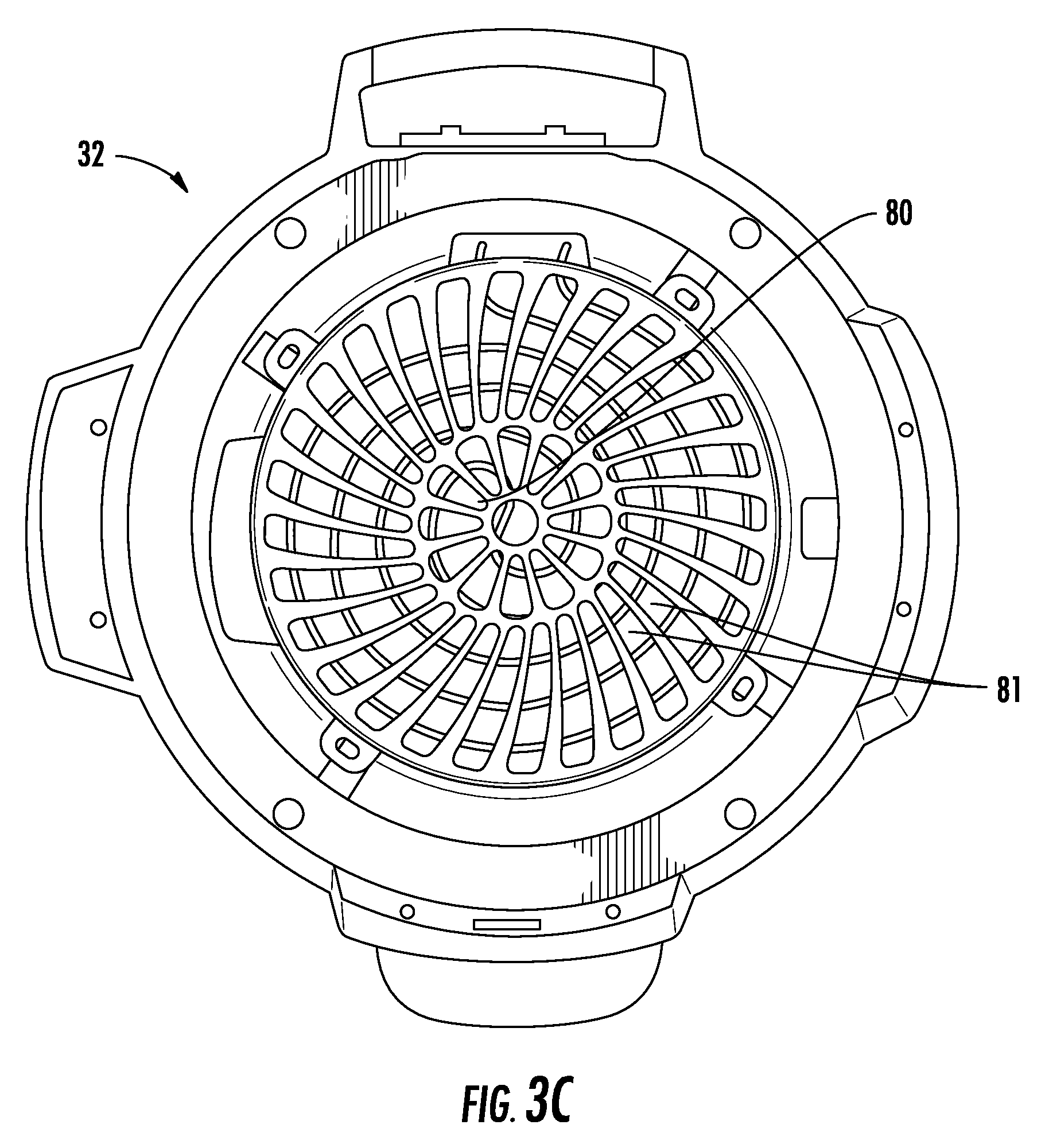
FIG. 3C is a lower view of a lid of the cooking system according to an embodiment;
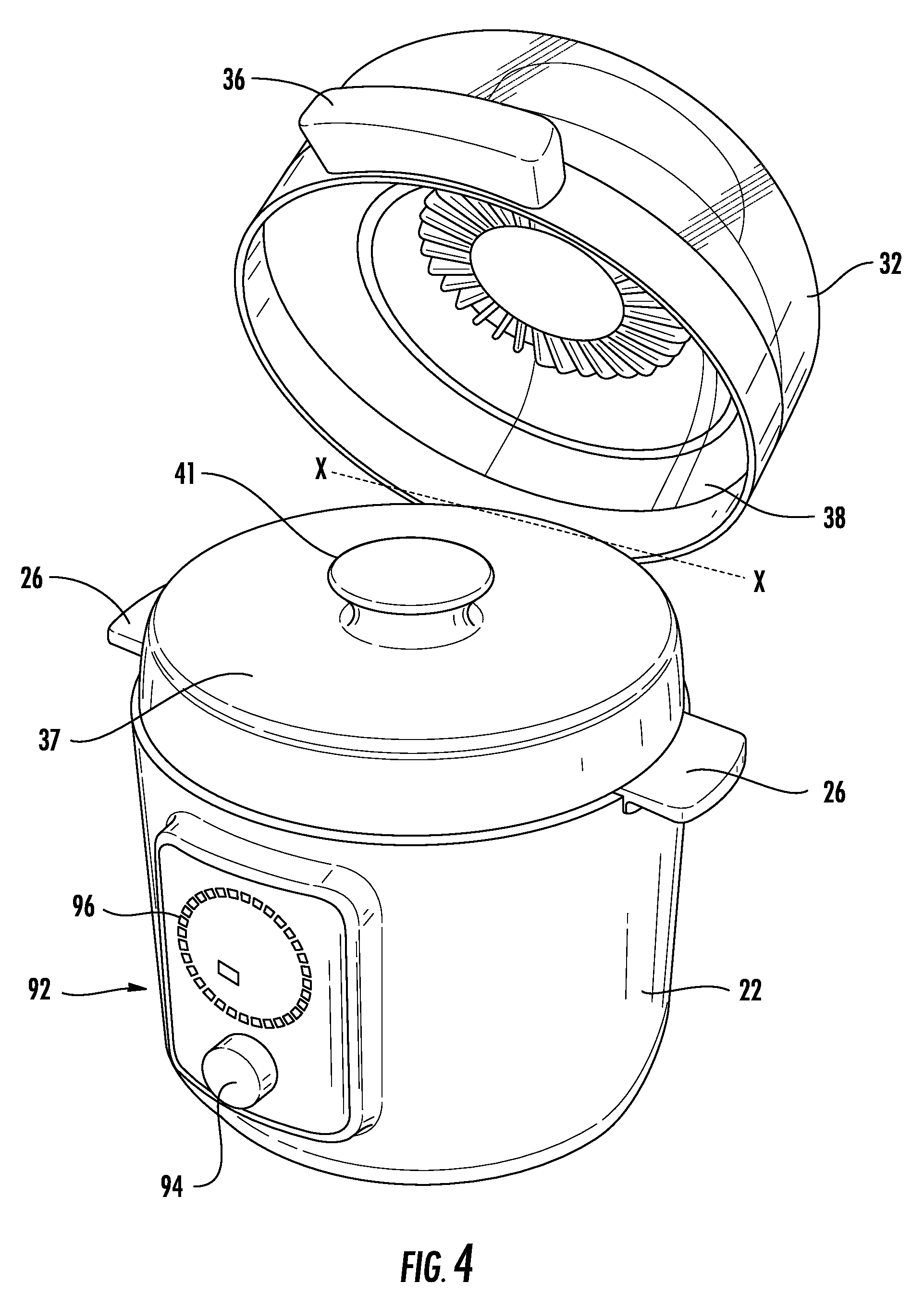
FIG. 4 is a perspective view of a cooking system having both a lid and a secondary lid in an open position according to an embodiment;
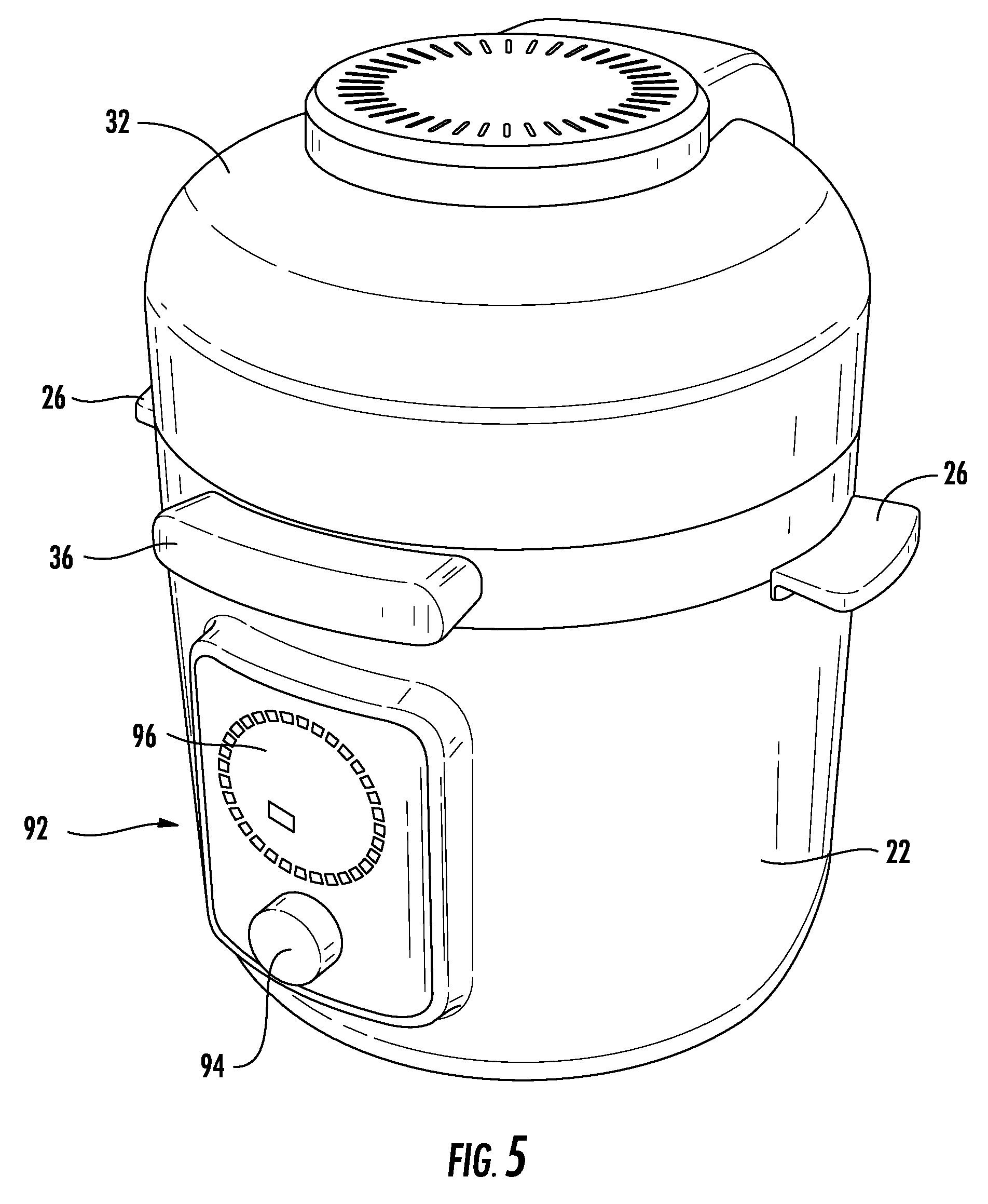
FIG. 5 is a perspective view of a cooking system having both a lid and a secondary lid in a closed position according to an embodiment;
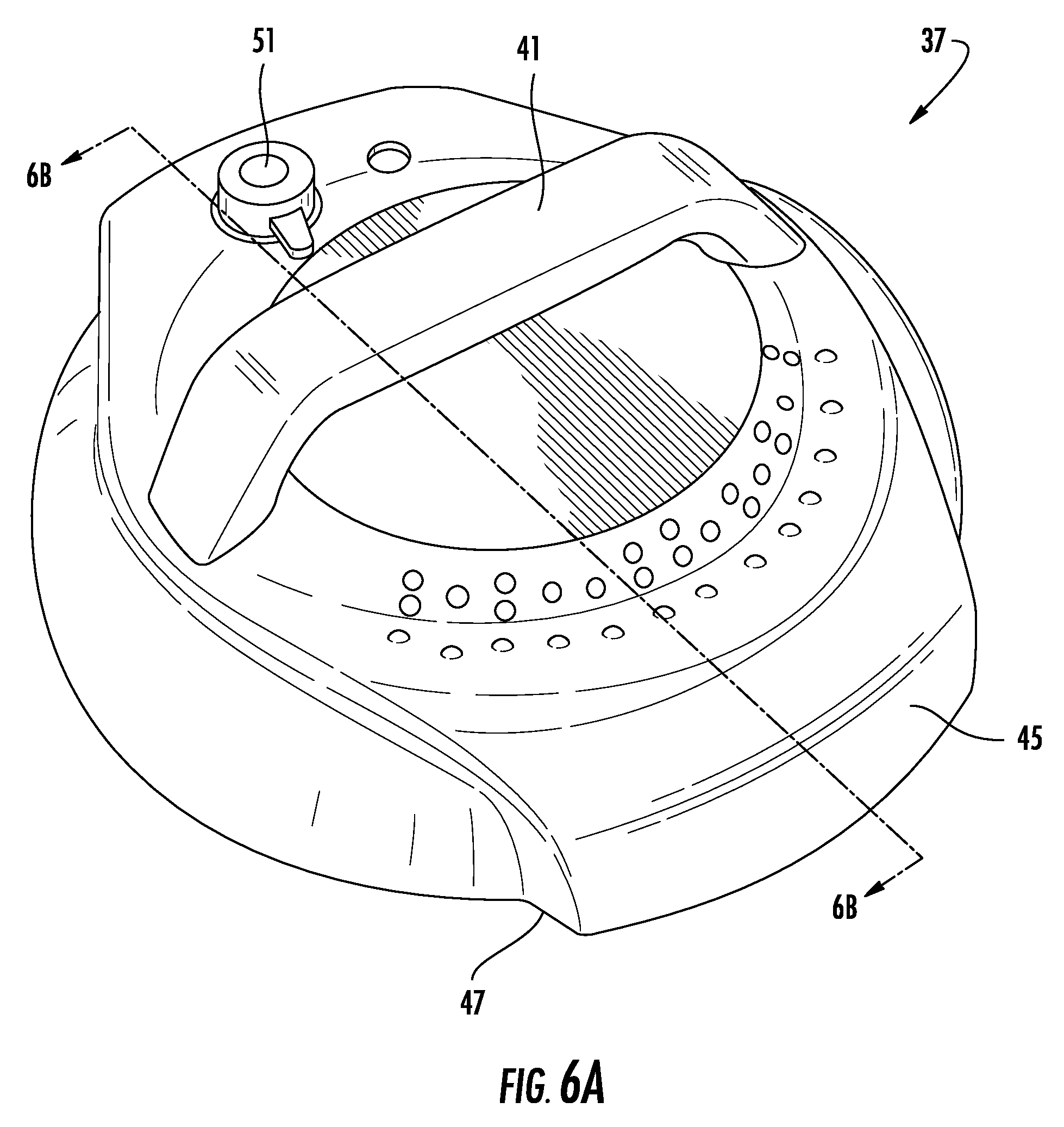
FIG. 6A is a perspective view of a lid of the cooking system according to an embodiment;
FIG. 6B is another perspective view of a lid of the cooking system according to an embodiment;
FIG. 7 is a schematic diagram of the cooking system according to an embodiment;
FIG. 8A is a perspective view of an air diffuser according to an embodiment;
FIG. 8B perspective lower view of an insert according to an embodiment;
FIG. 8C is a perspective view of an insert with attached diffuser according to an embodiment;
FIG. 8D is a side view of the insert according to an embodiment;
FIG. 9 is a perspective view of a diffuser received in a container according to an embodiment;
FIG. 10 is a perspective view of a cooking system having an insert positioned therein according to an embodiment;
FIG. 11 is a cross-sectional view of the cooking system according to an embodiment;
FIG. 12 is a block diagram illustrating a control path for a cooking system according to an embodiment;
FIG. 13 is a perspective view of the cooking system having a lid in an open position according to an embodiment;
FIG. 14 is a perspective view of a cooking rack for use in a cooking system according to an embodiment;
FIG. 15 is a perspective view of the cooking rack received in the cooking system according to an embodiment;
FIG. 16 is another perspective view of the cooking rack for use in the cooking system according to an embodiment;
FIG. 17 is a perspective view of the cooking rack received in the cooking system according to an embodiment;
FIG. 18 is another perspective view of the cooking rack for use in the cooking system according to an embodiment;
FIG. 19 is a table showing cooking parameters for use in a cooking system according to an embodiment;
FIG. 20 is a circuit diagram for use in a cooking system according to an embodiment;
FIG. 21 is a logic diagram for use in a cooking system according to an embodiment; and
FIGS. 22A, 22B, 22C, and 22D is an upper view of a series of lid positions in a cooking system according to an embodiment.
The detailed description explains embodiments of the disclosure, together with advantages and features, by way of example with reference to the drawings.
DETAILED DESCRIPTION
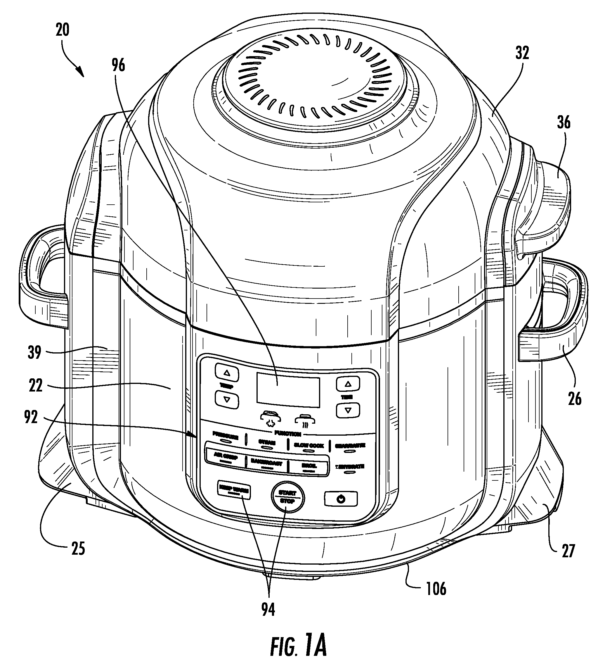
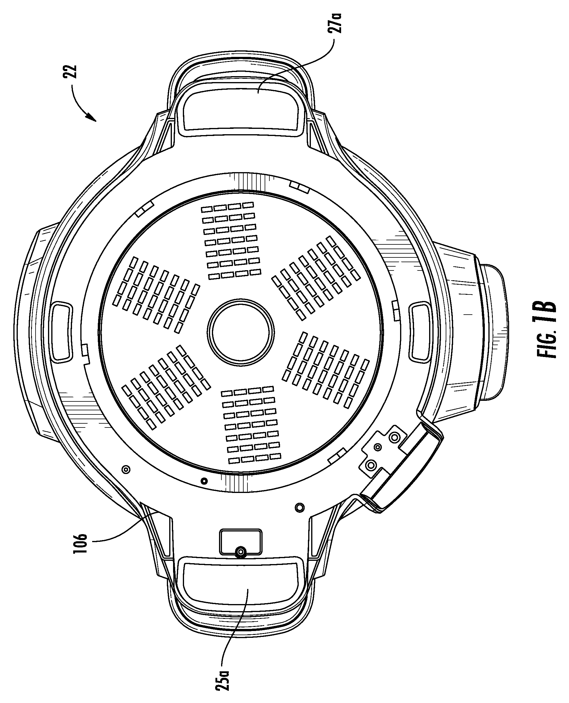
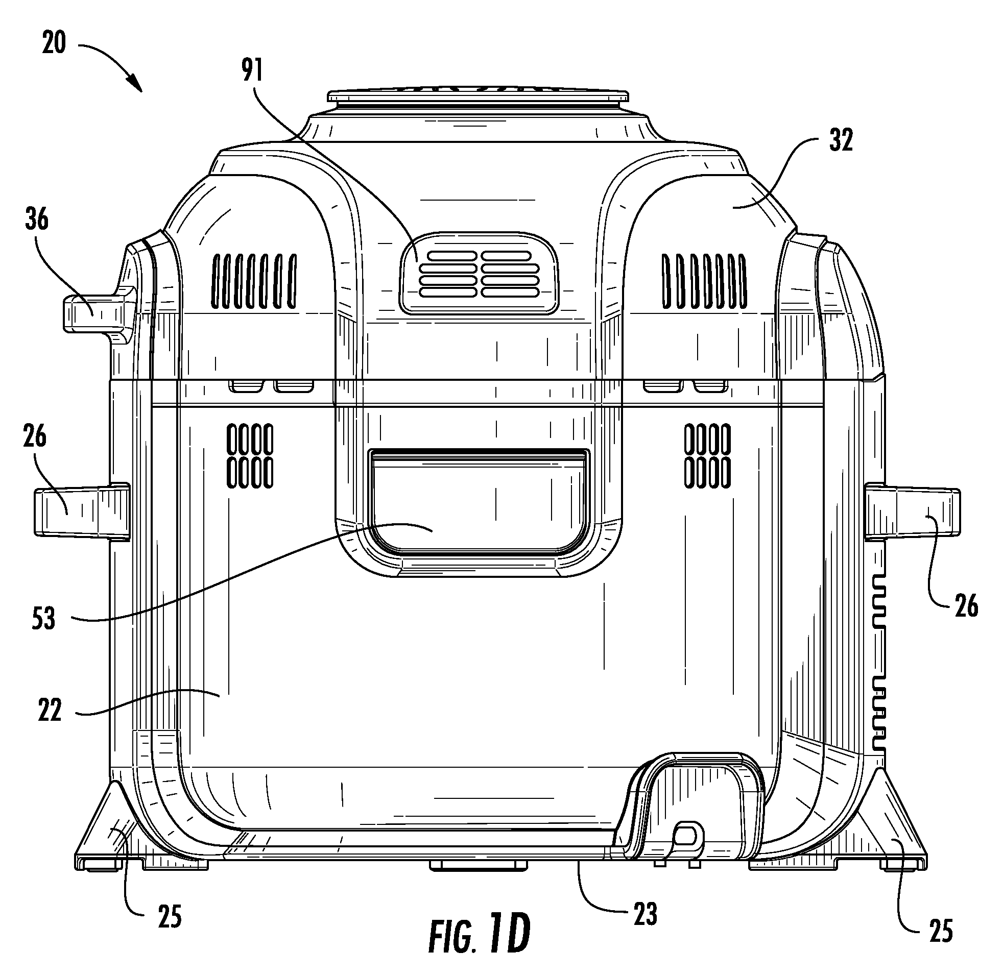
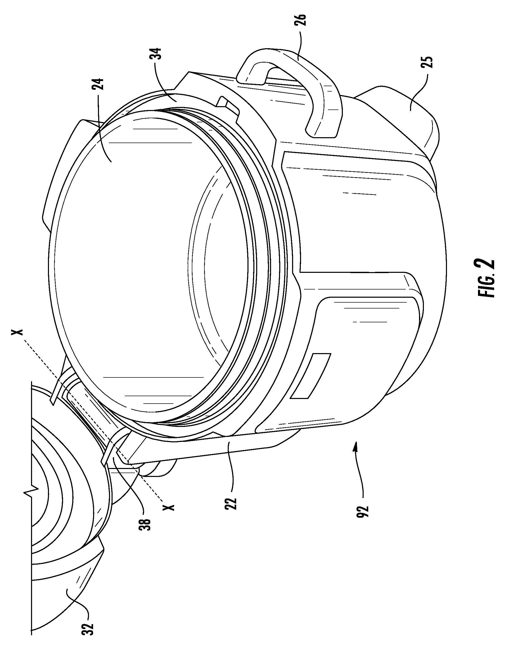
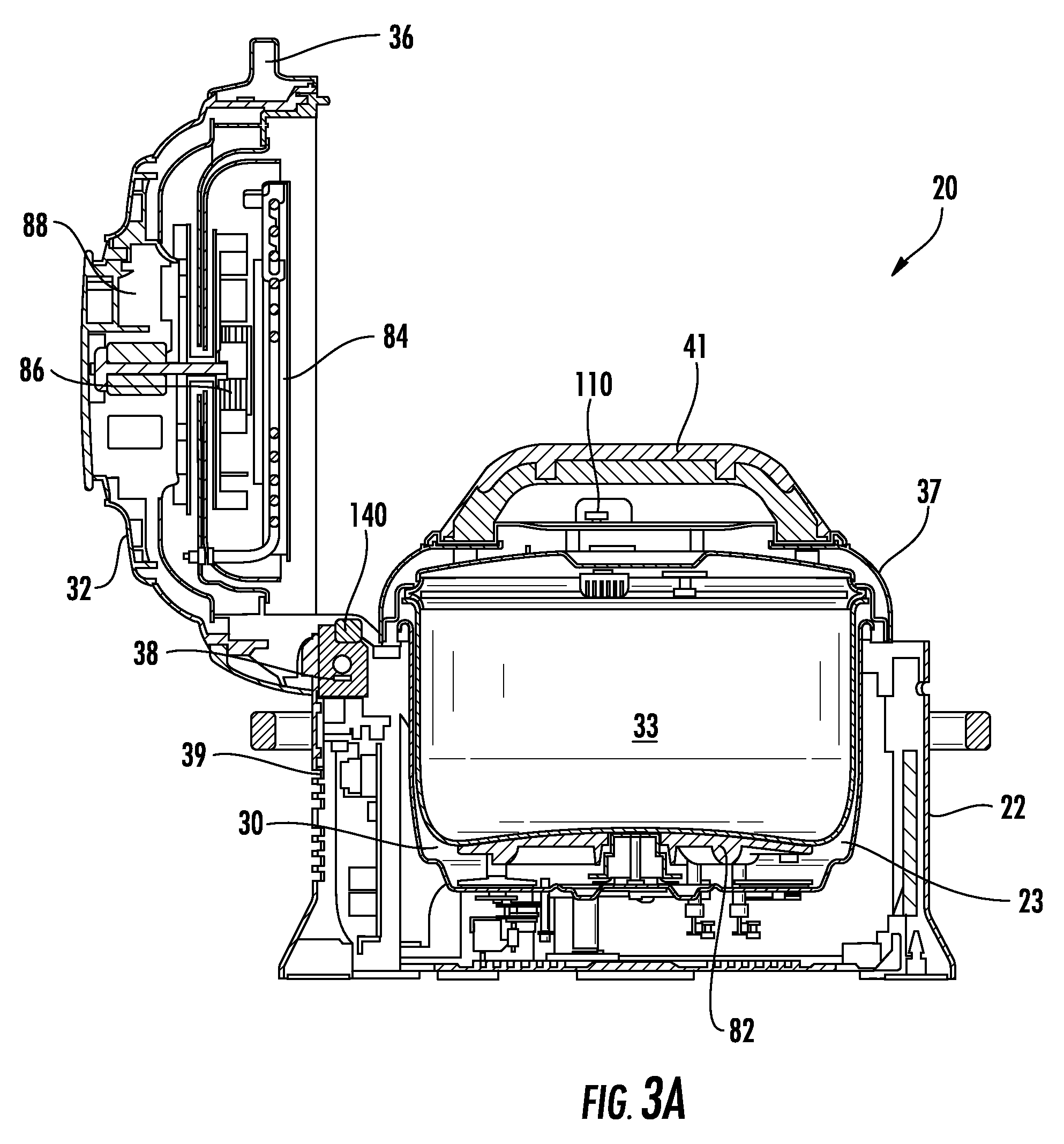
With reference first to FIGS. 1-7, a cooking system 20 configured to perform multiple cooking operations is illustrated. As shown, the cooking system 20 includes a housing 22 and a first or primary lid 32 permanently or removably attached, or more specifically hinged, to the housing 22. In an exemplary, non-limiting embodiment, the connection or hinge area between the lid 32 and the housing 22 occurs at an upper portion of a spine 39 of the housing 22. A bottom 106 of the housing 22 of the cooking system 20 (see FIG. 1B) may be supported on a surface by one or more feet 25 and 27, which may include shock absorbing pads 25a and 27a (of a material such as but not limited to rubber) at a bottom surface thereof. The feet 25, 27 may extend from the housing 22 to define a surface on which the cooking system 20 may contact an adjacent supporting surface, such as a countertop for example. The bottom surface of the feet 25, 27 or pads 25a, 27a may be flush with, or alternatively, may extend out of plane from the bottom 106 of the housing. In the illustrated, non-limiting embodiment, the housing 22 includes two feet 25, 27 arranged on opposing sides of the housing 22; however, it should be understood that a housing having any suitable number of feet 25 is within the scope of the disclosure.
Further, in the exemplary, non-limiting embodiment shown in at least FIGS. 1A-C, the foot 25 under the spine 39 is larger and extends out a greater distance from the side of the housing 22 than the foot 27. As shown in FIG. 1C, this allows for better support of the system 20 when the cooking system 20 is on a substantially flat surface or an inclined surface (up to 15 degrees in an exemplary embodiment) and the relatively heavy lid 32 is in an open position.
In the illustrated, non-limiting embodiment, one or more handles 26 extend outwardly from the exterior of the housing 22 to provide a user with a location to more easily grasp the system 20. Although two handles 26 are shown, embodiments having no handles, a single handle, or more than two handles are also within the scope of the disclosure. The housing 22 and/or the one or more handles 26 may be integrally or separately formed, such as from a molded plastic material for example. Referring now to some of the interior features of the system 20, an inner surface of the housing 22 defines a hollow interior 30. In an exemplary non-limiting embodiment, a liner 23 that may be formed from any suitable conductive material, such as aluminum for example is disposed within the hollow interior 30, and in some embodiments the liner 23 may be the inner surface defining the hollow interior (though surfaces inside the liner 23, such as the walls of the container, or outside the liner 23, such as plastic around the liner 23, may also define the hollow interior 30). In an exemplary, non-limiting embodiment, a food container 24 is receivable inside the hollow interior 30 defined by the liner 23. Spacing components, such as silicone bumpers (not shown) may be disposed along the inner surface of the liner 23 to keep the container 24 aligned properly within the hollow interior 30 during cooking. Although the container 24 is described herein as being removable from the housing 22, embodiments where the container 24 is integrally formed with the housing 22 are also contemplated herein. The container 24, which is shown in FIGS. 2 and 3A, has an interior 33 designed to receive and retain one or more consumable products, such as food products for example, therein. Examples of food products suitable for use with the cooking system 20, include but are not limited to, meats, fish, poultry, bread, rice, grains, pasta, vegetables, fruits, and dairy products, among others. The container 24 may be a pot formed from a ceramic, metal, or die cast aluminum material. In an embodiment, an interior surface of the container 24 includes a nano ceramic coating and an exterior surface of the container 24 includes a silicone epoxy material. However, any suitable material capable of withstanding the high temperatures and pressures required for cooking food products is contemplated herein.
Referring with more detail not to the lid 32, it should be noted that the lid 32 is connectable to a surface of the container 24 and/or housing 22 to close off entry to the hollow interior 30 of the container 24. In an embodiment, a diameter of the lid 3:2 is generally, complementary to a diameter of the housing 22 such that the lid 32 covers not only the container 24, but also an upper surface 34 of the housing 22. The lid 32 can be made of any suitable material, such as glass, aluminum, plastic, or stainless steel for example. Further, the lid 32 may, but need not, include one or more handles 36 for removably coupling the lid 32 to the remainder of the cooking system 20. In the illustrated, non-limiting embodiment, the lid 32 is coupled to the housing 22 via a hinge 38 (best shown in FIG. 3A just above the spine 39), such that the lid 32 is rotatable about an axis X between an open position (FIG. 3) and a closed position (FIG. 1A). In such embodiments, the hinge axis X may be located at a side surface of the cooking system 20, as shown in FIG. 2, or alternatively, at a back surface of the cooking system 20, such as vertically disposed relative to one or more handles 26 of the housing 22, as shown in FIG. 4. However, embodiments where the lid 32 is separable from the housing 22, or movable between the open and closed positions in another manner are also contemplated herein. One or more fastening mechanisms (not shown) may, but need not be used to secure the lid 32 to the housing 22 when the lid 32 is in the closed position. Any suitable type of fastening mechanism capable of withstanding the heat associated with the cooking system 20 is considered within the scope of the disclosure. In an embodiment, best shown in FIGS. 3A-C, 4-5, and 6A-B, the cooking system 20 additionally includes a secondary lid 37 configured to removably couple to the housing 22 and/or container 24 to seal the hollow interior 30. In an embodiment, the secondary lid 37 is press-fit onto an upper surface 34 of the housing 22 or directly to the container 24. In another embodiment, the secondary lid 37 is configured to thread-ably couple to the upper surface 34 of the housing 22 or the container 24. However, embodiments where the secondary lid 37 is configured to couple to at least one of the housing 22 and container 24 in another suitable manner, such as via a pressure tight mechanism for example, are also contemplated herein. The secondary lid 37 can be made of any suitable material, such as glass, aluminum, plastic, or stainless steel, or any combination thereof for example. In an embodiment, the secondary lid 37 is formed from a molded plastic material. In addition, the secondary lid 37 may, but need not, include one or more handles 41 for removably coupling the secondary lid 37 to the cooking system 20. The handle 41 may be integrally formed with the remainder of the lid 37, such as via a molding process, or alternatively, may be a separate component coupled to the lid 37.
As best shown in FIG. 6B, the secondary lid 37 includes an interior liner 43, also referred to as an "underliner" formed from any suitable material, such as stainless steel for example. In an embodiment, one or more threads may be formed in the underliner 43 to couple the lid 37 to an end of the container 24. As shown, the lid 37 may additionally include a lid support ring 45 having a diameter extending beyond the outer diameter of the underliner 43 about at least a portion of the circumference thereof. In an embodiment, a surface 47 of the lid support ring 45 may be configured to abut the upper surface 34 of the housing 22 when the secondary lid 37 is coupled to the container 24. A lid cushion 49, such as formed from a resilient or elastomeric material, such as rubber for example, may be disposed at an exterior surface of a portion of the lid 37, such as between the under-liner 43 and the lid support ring 45 for example. Further, a pressure relief valve 51 (see FIG. 6A) is formed in a surface of the secondary lid, such as the upper surface thereof for example. The pressure relief valve is configured to automatically open to release air from within the chamber formed between the secondary lid 37 and the container 24 when the pressure therein exceeds a predetermined threshold. Alternatively, or in addition, the pressure relief valve is manually operable to release air from within the chamber formed between the secondary lid 37 and the container 24.
To couple the secondary lid 37 to the housing 22, the primary lid 32 must be in an open position, as shown in FIGS. 3A and 3B. Further, in an embodiment, the primary lid 32 is not movable to the closed position relative to the housing 22 when the secondary lid 37 is affixed thereto. This may be due to the outer diameter of the secondary lid 37, or alternatively, because one or more components extending upwardly from the lid 37, such as handle 41, would interfere with a portion of the primary lid 32. However, in other embodiments, as shown in FIGS. 4 and 5, at least a portion of the secondary lid 37 may be nestable or receivable within the primary lid 32. In such embodiments, the outer diameter of the secondary lid 37 may be smaller than the inner diameter of the primary lid 32, such that the primary lid 32 substantially surrounds the secondary lid 37 when in the closed position. Accordingly, the enclosure defined by the hollow interior 30 of the container 24 and the secondary lid 37 is smaller than the enclosure formed by the hollow interior 30 of the container 24 and the primary lid 32. Although the cooking system 20 is illustrated and described herein including the secondary lid 37, it should be understood that in some embodiments the cooking system 20 includes only a primary lid 32 and does not include a secondary lid 37.
With reference again to FIG. 2, a condensation rim may be formed in upper surface 34 of the housing 22, radially outward of the opening and/or container 24. During operation of the cooking system 20, condensation or other fluid circulating within the container 24 and/or hollowed interior 30 of the system 20 may collect within the condensation rim. In an embodiment, best shown in FIG. 1D, a condensation tray 53 arranged in communication with the interior 30 of the container 24. The condensation tray 53, may, but need not, be arranged in fluid communication with the condensation rim of the upper surface 34. As shown, the condensation tray 53 is accessible via the back surface of the housing 22 and is configured to removably couple to the housing 22 to allow a user to empty the contents of the tray 53. When connected to the housing 22, the condensation tray 53 may be suitable to form a pressure tight seal with the housing 22.
With specific reference now to FIG. 7, the cooking system 20 includes at least one first heating element 82 and at least one second heating element 84 configured to impart heat to the hollow interior and/or container 24 during various modes of operation of the cooking system 20. As shown, one or more first heating elements 82 may be disposed at the base 28 of the housing 22, generally adjacent the bottom 31 of the container 24; though, embodiments where one or more of the first heating elements 82 are arranged adjacent a side of the housing 22, in addition to or in place of the base 28 of the housing 22, are also contemplated herein. The second heating element 84 may be positioned generally at or above an upper extent of the container 24, proximate an upper opening of the container. However, in the exemplary non-limiting embodiment shown in the Figures, the second heating element 84 is disposed in the lid 32, and therefore completely outside of the container 24, above the upper extent thereof.
With reference again to FIGS. 1A, 4, 5, and reference to FIG. 10, a control panel or user interface 92 of the cooking system 20 is positioned adjacent one or more sides of the housing 22. The control panel 92 includes one or more inputs 94 associated with energizing the one or more heating elements 82, 84 of the cooking system 20 and for selecting various modes of operation of the cooking system 20. One or more of the inputs 94 may include a light or other indicator to show that the respective input has been selected. The control panel 92 may additionally include a display 96 separate from and associated with the at least one input 94. However, embodiments where the display 96 is integrated into the at least one input 94 are also contemplated herein.
Operation of the one or more inputs 94 will be described in more detail below. As shown in FIG. 12, a control system 100 of the cooking system 20 includes a controller or processor 102 for controlling operation of the heating elements 82, 84 (and air movement device 86 including the motor 88 and fan 90 associated therewith, which will be discussed in greater detail below), and in some embodiments for executing stored sequences of heating operation. The processor 102 is operably coupled to the control panel 92 and to the heating elements 82, 84 and the air movement device 86. In addition, in an exemplary embodiment, one or more sensors S for monitoring one or more parameters (such as temperature, pressure, lid configuration, etc.) associated with operation of the heating elements 82, 84 and/or lids 32, 37 may be arranged in communication with the processor 102. In an embodiment, a first temperature sensor extends from a bottom surface 108 of the liner 23 proximate the first heating element 82 and bottom surface of the container 24, and a second temperature sensor is located within the lid 32 proximate the second heating element 84. In such embodiments, the second sensor may be used, such as to monitor temperature for example, when the lid 32 is closed and the sensor S is arranged in fluid communication with the hollow interior 30 of the system 20. The first sensor may be used to monitor temperature in this manner, separately or in conjunction with the second temperature sensor.
In an embodiment, at least one input 94 on the control panel 92 is an on/off button which allows the user to activate or deactivate the control panel 92. When the control panel 92 is deactivated, none of the heating elements 82, 84 are energized. In an exemplary embodiment, the at least one input 94 is operable to select one or more manual modes of operation of at least one of the heating elements 82, 84. Alternatively, or in addition, at least one input 94 is operable to select a stored sequence of operation of at least one heating element 82, 84. In some cases, the stored sequences may be particularly well suited for a given method of food preparation and/or for particular ingredients or types of ingredients. The plurality of stored sequences associated with the at least one input 94 may be stored within a memory accessible by the processor 102. Alternatively, the plurality of stored sequences may be stored remotely from the cooking system 20, and may be accessed by the processor 102, such as via wireless communication for example.
In addition, a user may be able to enter a time associated with operation of the cooking system 20 in a desired manual mode. The time may be entered via the same input, or a separate input as used to select a mode of operation. Further in embodiments where the system 20 is in a mode configured to perform a stored sequence in response to selection of one of the inputs 94, the display 96 may indicate a time remaining on the display. Temperature and pressure parameters may also be entered via inputs 94.
The at least one input 94 may include a distinct start button intended to initiate operation in a desired mode, a distinct stop button to cease all operation, or a stop/start button intended to initiate and cease functions. Alternatively, the cooking system 20 may be operable to automatically start operation after a predetermined time has elapsed once an input has been selected and any necessary information has been provided to the control panel. Alternatively, one or more of the other inputs 94, such as the knob for example, may be operable, such as by pushing the knob towards the control panel 92, to start and stop operation of the cooking system 20, regardless of whether the system 20 is following a stored sequence or is in a manual mode.
The one or more inputs 94 are operable to initiate manual operation of the cooking system 20 in at least a first cooking mode and a second cooking mode. In an embodiment, the first cooking mode employs first heating element 82 to perform conductive cooking operations. Conductive cooking operations may generally be referred to as "wet cooking" operations, such as but not limited to pressure cooking, steam cooking, slow cooking, searing, and sauteing. To create a wet cooking environment the majority of the moisture within the container, i.e. liquid added to the container 24 or moisture released from the food within the container 24, is retained within the container as the food is cooked. Although during conductive cooking operations a minimal amount of air having moisture entrained therein may be vented from the system, such air is passively removed from the cooking enclosure. Similarly, the second cooking mode employs the second heating element 84 to perform convective heating operations. Convective heating operations may generally be referred to as "dry cooking operations," which include any cooking mode that creates a "dry cooking environment" within the container 24, such as but not limited to air frying, broiling, baking/roasting and dehydrating. To create a dry cooking environment, air and moisture are actively exhausted or vented from the cooking enclosure to outside the cooking system 20, thereby maintaining a minimum level of moisture within the container 24. Parameters associated with the various exemplary but non-limiting cooking modes are shown at FIG. 19.
As is noted above, the first cooking mode of the cooking system 20 includes pressure cooking. In such embodiments, the secondary lid 37 is affixed to the container 24 or housing 22 to form a pressure-tight, sealed enclosure with the container 24. During operation in the pressure cooker mode, the controller 102 initiates operation of the first heating element 82, causing the temperature and therefore the pressure, within the enclosure formed by the container 24 and the secondary lid 37 to rise. During operation in the pressure cooker mode, the second heating element 84 disposed within the primary lid 32 is typically not energized. In an embodiment, the cooking device 20 may include a sensor S configured to monitor the pressure within the enclosure. Upon detection that the pressure is at or exceeds a predetermined threshold, the controller 102 may de-energize the heating element 82 until the pressure within the enclosure has returned to an acceptable level. Alternatively, or in addition, a pressure relief valve 51 (see FIG. 6A) may be formed in the secondary lid 37, and may open to reduce the pressure within the enclosure to below the threshold. The pressure relief valve 51 may be configured to open automatically when the pressure is above the threshold, or the valve 51 may be coupled to the controller 102 and may be operable in response to a signal generated by the controller 102, for example in response to sensing a pressure above the threshold. In embodiments where the cooking system 20 is operable in a slow cooking mode, but not a pressure cooking mode, the liner 23 of the housing 22 may be formed from a light weight, cost effective material, such as aluminum for example. However, in embodiments where the cooking system 20 is operable in a pressure cooking mode, the liner 23 should be formed from a more rigid material capable of withstanding the pressure build up within the container 24. As is noted above, the first cooking mode of the cooking system 20 also includes slow cooking, steaming, searing, and sauteing. When the cooking device 20 is operated in one of these non-pressure modes, either the secondary lid 37 may be affixed to the container 24 or housing 22 or the primary lid 32 may simply be closed.
During slow cooking, steaming, searing, and sauteing (or other conductive cooking means that do not involve "pressure cooking"), the controller 102 initiates operation of the first heating element 82, causing the temperature within the container 24 and at the bottom surface thereof to increase. Upon detection that the temperature of the chamber 30 is equal to or exceeds a predetermined threshold, the controller 102 may de-energize the heating element 82 until the temperature has returned to an acceptable level. Such de-energization or power termination to the heating elements 82 and 84 based on detection of unsafe conditions by temperature or pressure sensors S will be discussed in greater detail below.
As previously suggested, the at least one input 94 is also usable to select operation of the cooking device 20 in a second cooking mode that employs convective cooking such as air frying. In an exemplary, non-limiting embodiment, air frying in the system 20 involves the use of various components such as the fan 90, and a basket 52 and diffuser 40.
With reference now to FIGS. 8A-D and 9, an air diffuser 40 is shown. The diffuser 40 is an optional system component that may benefit air circulation during the air frying mode. The diffuser is positionable anywhere in the hollow interior 30 (though typically near the bottom). In an exemplary, non-limiting embodiment, the diffuser is positioned in contact with a bottom surface 31 of the container 24, and, as will be discussed in greater detail below, used in conjunction with an insert 52.
As shown in the Figures, the air diffuser 40 may include a plurality of vanes 42 spaced about a center body 44. Each of the plurality of vanes 42 is configured to impart swirl to an air flow circulating through the container 24. In the illustrated, non-limiting embodiment, the air diffuser 40 includes four vanes 42. However, embodiments where the air diffuser 40 includes one vane, two vanes, three vanes, or more than four vanes are also within the scope of the disclosure. Further, although the vanes 42 are illustrated as being substantially identical and equidistantly spaced about the center body 44, embodiments where a configuration of one or more of the vanes 42 varies and/or the spacing between adjacent vanes 42 varies are also contemplated herein. In an embodiment, each of the vanes 42 of the air diffuser 40 has a radius of curvature such that the vanes 42 curve generally from the center body 44 of the air diffuser outwardly. In addition, the vanes 42 of the air diffuser 40 extend generally perpendicularly in an upward direction from the bottom surface 31 of the container 24, and a lower extent of the vanes 42 generally lengthens as the vanes move out from the center body 44 towards the outer edge 46. However, an air diffuser 40 including one or more vanes having another configuration are also within the scope of the disclosure.
In an exemplary, non-limiting embodiment, the upper surface 48 and the distal ends 46 of the vanes 42 cooperate to define an area 50 within which the insert 52 may be removably mounted. With reference to FIGS. 8A-D and 9, the insert 52 includes a body 54 having a first, open end 56, second, aperture end 58, and at least one sidewall 60 extending between the first end 56 and second end 58 to define a hollow interior or chamber 62 defined by the body 54. The first end 56 is generally open to provide access for positioning one or more food items within the chamber 62. The second end 58 of the body 54 is partially closed to retain one or more food items within the chamber 62. In an exemplary, non-limiting embodiment, the closed second end 58 of the body 54 defines a plurality of apertures 59 (see FIG. 8B) to allow air, heat, and/or steam flowing within/through the interior 33 of the container 24 may pass through the apertures 59 in the end 58 to cook one or more food items within the chamber 62 of the body 54.
When the insert 52 is positioned within the area 50, in contact with the upper surface 48 of the air diffuser 40, and the insert 52 with air diffuser 40 is disposed within the interior 33 of the container 24, the bottom surface 58 of the insert 52 is positioned to be offset from the bottom surface 31 of the container 24. The offset spacing is via presence of the vanes 42 between the surfaces 58 and 31, allowing air moving through the system 20 to flow underneath the insert 52. In an embodiment, a tab 64, best shown in FIG. 8A, protrudes from the upwardly extending portion of each vane 42. As shown, the tabs 64 generally protrude inwardly, towards the center body 44 of the air diffuser 40. The tabs 64 may be sized and contoured to cooperate with a ridge or groove 65 formed in the exterior surface of the insert 52 to retain the insert 52 in position adjacent the air diffuser 40. Of course, embodiments wherein the diffuser 40 is integrally formed with either the insert 52 or bottom surface 31 and/or side surfaces of the container 24 are also contemplated.
Although the body 54 of the inserts 52 illustrated are shown having a single chamber, embodiments where the body 54 includes a plurality of chambers are also contemplated herein. As previously described, the closed second end 58 of the body 54 has a generally porous structure, which may also be formed via mesh or wire for example (see FIG. 10), so that heat and/or steam flowing through the interior 33 of the container 24 may pass through the openings in the porous structure to cook one or more food items within the chamber 62 of the body 54. One or more handles 66 may be associated with the body 54 to allow a user to easily grasp the insert 50. In the illustrated, non-limiting embodiment, the body 54 includes two handles 66 extending from the sidewall 60, or alternatively, integrally formed into the sidewall 60 of the body 54 as openings. However, any suitable configuration of the body 54 and/or handles 66 is within the scope of the disclosure. Such configurations may include removable handles.
In embodiments where the air diffuser 40 and the insert 52 may be integrally formed, as shown in FIG. 10, the insert 52 may additionally include a base 70 having an upper surface 72 and a lower surface (not shown). The base 70 may have a size and/or shape generally complementary to the body 54, and both the base 70 and body 54 may have a similar shape to the interior 33 of the container 24. In the illustrated, non-limiting embodiment, the interior 33, and the insert 52 are both generally cylindrical in shape.
The base 70 is generally offset from the second end 58 of the body 54 by a distance. As a result, a gap or clearance 74 defining a fluid flow path is formed between at least a portion of an upper surface 72 of the base 70 and the second end 58 of the body 54. In the illustrated, non-limiting embodiment, the lower surface (not shown) of the base 70 of the insert 52 has a generally planar configuration for directly contacting an adjacent supporting surface of the container 24, such as the bottom surface 31, when the insert 52 is installed therein. In embodiments where the supporting surface of the container 24 does not have a planar configuration, the configuration of the lower surface of the base 70 will be complementary to the supporting surface.
As previously described, in an embodiment, the air diffuser 40 comprising one or more vanes configured to impart swirl to air moving through the clearance 74 towards the second end 58 of the body 54 may be formed in the upper surface 72 of the base 70. In such embodiments, the configuration of the air diffuser 40 may be the same, or alternatively, different than in embodiments where the air diffuser 40 is a separate component. As shown, the vanes 42 of the air diffuser 40 integrally formed with the insert 52 have a radius of curvature such that the vanes 42 curve generally from an outer edge of the base 70 towards a center thereof. In addition, the vanes 42 of the air diffuser 40 extend generally perpendicular to the upper surface 72, and the height of the vanes 42 measured perpendicular to the upper surface 72 increases from the outer edge of the base 70 towards the center. Although the air diffuser 40 is described as being integrally formed with the insert 52, in other embodiments, all or a portion of the air diffuser may alternatively, or in addition, be integrally formed with a portion of the container 24.
Regardless of whether the insert 52 is integrally formed with or coupled to the air diffuser 40, when the insert 52 and air diffuser 40 are arranged within the interior 33 of the container 24, an annulus 76 is formed between an inner surface 78 of the container 24 and the sidewalls 60 of the body 54 (see FIG. 7). Further, in an exemplary non-limiting embodiment the height of the insert 52, when installed within the container 24 with the air diffuser 40, may be generally equal to or less than height of the container 24. In embodiments where the cooking system 20 includes a secondary lid 37, either the primary lid 32 or the secondary lid 37 may be used, i.e. coupled to the upper surface 34 of the housing 22 when the insert 52 is positioned generally within the hollow interior 30 of the system 20 or specifically within the interior 33 of the container 24.
It should be appreciated that the insert 52 may also be received directly in the hollow interior 30 as opposed to within the container 24 within the hollow interior 30. That is, the insert 52 (and diffuser 40) may be disposed in the system without the container 24, and food may be cooked in the insert 52 in accordance with of the second mode, convective cooking functions.
With further reference to second, convective cooking mode functions (particularly air frying modes), the second heating element 84 is configured to heat air as it passes there through via an air movement device 86, such as a fan for example. In embodiments where the insert 52 is arranged within the interior 33 of the container 24, the air movement device 86 draws air from the center of the insert 52, and moves it across the second heating element 84 before forcing the heated air through the annulus 76 between the container 24 and the insert 52 towards the clearance 74 formed between the bottom 58 of the insert and the bottom surface 31 of the container 23 (the arrows in FIG. 7 show exemplary air flow through the system). This air movement may be facilitated via air guides such as a skirt/air guide 89 that creates a non-sealing air guide for air into the annulus 76. In the illustrated, non-limiting embodiment of FIGS. 7 and 11, the air movement device 86 is driven by a motor 88 having a separate cooling mechanism 90 coupled thereto. In an embodiment, a vent 91 is formed in the primary lid for exhausting hot air generated by operation of either the air movement device 86, the motor 88, or the separate cooling mechanism 90 to the exterior of the cooking system 20. However, it should be understood that the second heating element 84 and the air movement device 86 may also be used to circulate air through the enclosure defined between the container 24 and the primary lid 32 when the insert 52 and/or air diffuser 40 are not arranged within the container 24. As is shown in the exemplary embodiments of the Figures, the at least one second heating element 84 is disposed within the primary lid 32. In an embodiment, the second heating element 84 has a diameter substantially equal to the diameter of the body 54 of the insert 52. However, embodiments where the second heating element 84 has a diameter smaller than or greater than the diameter of the body 54 of the insert 52 are also contemplated herein.
When utilizing the second heating element 84 in the air fryer mode, the controller 102 initiates operation of the second heating element 84 and the air movement device 86 to circulate the hot air represented by the arrows in FIG. 7 through the enclosure formed between the container 24 and the lid 32. During operation in the air fryer mode, the first heating element 82 is generally not energized. However, embodiments where the first heating element 82 is energized are also within the scope of the disclosure.
The air movement device 86 draws air upward through the adjacent heating element 84 and expels the hot air outwardly towards the guide 89 (which, in an exemplary embodiment, actually surrounds the fan 86). The guide 89 deflects the air downwardly towards the annulus 76 along the sides of the container 24 (again, please see the arrows in FIG. 7). The air travels down through the annulus 76 (still by actuation of the fan 86) until it is deflected off the bottom surface 31 of the container 24 and drawn up by the fan 86 into the clearance 74 up towards the diffuser 40 and end 58 of the insert 52 with the aperture pattern 59. The hot air flows over and between the plurality of vanes 42 of the air diffuser 40, which impart a rotational motion to the hot air, thereby creating a vortex as the air is drawn through the apertures 59 and into the chamber 62 of the body 54 by the air movement device 86. After traversing the chamber 62, the air is drawn back up through the heating element 84 and into the fan 86 for further circulation.
As the air circulates through the chamber 62 in the manner described above, the hot air cooks and forms a crispy outer layer on the food items disposed therein as a result of the Maillard effect. In an embodiment, a liquid, such as oil or fat, is contained within the enclosure, such as adjacent the bottom surface 31 of the container 24. The liquid may be added to the container 24 prior to operation in the air fry mode, or alternatively, may be produced as a residual material as the hot air passes over the food within the chamber 62. In embodiments where a liquid is disposed at the bottom of the container 24, as the air circulates through the interior 30 of the container 24, a portion of the liquid becomes entrained in the air flow and is heated.
As is best shown in FIG. 3C, in an exemplary embodiment the lid 32 includes a heater/fan cover 80 that protects a user from the heating element 84 and fan 86, and protects the heating element 84 and fan 86 from the areas 31,33,64 where food is cooked. The cover 80 may be included in embodiments of the cooking system 20 including only a primary lid 32, or alternatively, in embodiments including both the primary and secondary lids 32, 37. In the illustrated, non-limiting embodiment, the cover 80 is formed from a nano ceramic coated and is mounted to the primary lid 32, such as via one or more fasteners for example. In such embodiments, when the primary lid 32 is in the closed position, the cover 80 is arranged generally above the first open end of the container 24. The cover 80 has a plurality of openings 81 formed therein to allow hot air circulating within the chamber of the container 24 to pass there through.
In another convection cooking embodiment, the second cooking mode of the cooking system 20 includes a dehydrator mode, such as used to make jerky for example. In such embodiments, the primary lid 32, is typically affixed to the container 24 or housing 22, though the secondary lid 32 may also be used. When the cooking device 20 is operated in the dehydration mode, the air diffuser 40 and/or insert 52 may, but need not be, positioned within the interior 30 of the container 24. During operation in the dehydrator mode, air is configured to circulate through the container 24 in a manner similar to the air fryer mode.
In an embodiment, the air movement device 86 of the cooking system 20 is a variable speed fan operable at a plurality of rotational speeds. In an embodiment, the operational speed of the air movement device 86 may vary based on the cooking mode selected (see the exemplary, non-limiting parameters and speeds set forth in FIG. 19). For example, the speed of the air movement device 86 during operation in an air fryer mode may be different than the speed of the air movement device during operation in a dehydrator mode. The operational speed of the air movement device 86 may be controlled by the controller 102 in response to one or more inputs 94, including selection of a cooking mode. However, the controller 102 may also be configured to adjust the operational speed of the air movement device 86, or alternatively, the power supplied to the one or more heating elements 82, 84, to control the temperature and/or pressure within the hollow interior 30 of the container 24.
The first and second heating elements 82, 84 are operable independently or in combination to apply one or more predetermined power settings to cook the food products within the container 24 and/or insert 52. In operation, the heating elements 82, 84 are capable of cooking the food products independent of the loading of the food products. In other words, the heating elements 82, 84 are capable of cooking the food products independent of the mount of food products within the container 24.
In some embodiments, the cooking system 20 is operable in more than two cooking modes. For example, the cooking system 20 may be independently operable in any of a slow cooking mode, a pressure cooking mode, an air fryer mode, and a dehydrator mode. Alternatively, or in addition, the at least one input 94 may be used to select operation of the cooking device 20 in a cooking mode that functions as a combination of two or more cooking modes. In such embodiments, the controller 102 may execute a stored sequence where the first heating mechanism 82 is operated during a first portion of the sequence and the second heating mechanism 84 and air movement device 86 are operated during a second portion of the sequence. For example, in the combination mode, a food item, such as a chicken for example, may be slowly cooked or pressure cooked via operation of the first heating element 82. Then, the second heating element 84 and the air movement device 86 may be operated to air fry the chicken to achieve a crispy exterior layer. However, the embodiments described herein are intended as an example only and any sequence of operation combining both the first and second heating elements is contemplated herein. When operated in a combination of two or more cooking modes, such as a pressure cooker and an air fryer, the food need not be removed from the hollow interior 30, or more specifically the container 24, or even more specifically from the chamber 62 of the insert 52 during such a transition.
As is alluded to above, the container 24 may be usable in both the first and second cooking modes. In an exemplary embodiment, convective cooking (first mode), and more specifically air frying is possible in a container (such as container 24) that is deformable for use in a pressure cooking environment (second mode). Containers in which pressure cooking occurs may deform in response to pressure conditions within the pot during cooking. A "domed" or curved shape 100 in a bottom surface 102 (see FIG. 11) of pressure pot such as container 24 may also be employed to handle pressure conditions and the deformity that may result therefrom. Accordingly, since the container 24 may also be used as an air frying chamber, exemplary embodiments of air frying components such as the insert 52 and diffuser 40 may be configured for use in pressure cooking environments. For example, the diffuser 40 may include a curved or sloped bottom surface 104 that conforms to the domed/curved/sloped shape 100 of the bottom surface 102 of the container 24. Indeed, the bottom surface 104 of the diffuser 40 may be curved or sloped to conform to a potentially domed surface of any container (again, such as container 24) used in for wet cooking modes such as but not limited to pressure, steam, slow cooking.
In accordance with the above, the insert 52 may be placed in the container 24 with food to be cooked in the first and second modes consecutively. For example, the insert 52 may be placed in the container 24 and food may be placed within the insert for cooking in a first, conductive modes such as pressure or slow cooking. The system 20 may then be switched into the second, convective mode, and the food still contained in the insert 52 contained in the container 24 can be cooked in accordance with a convection heating function. In an exemplary embodiment involving pressure cooking and air frying, such a process would involve placing food in the insert 52 and placing the insert in the container 24. The secondary lid 37 would be affixed to the system 20 and pressure cooking would/could occur. Once the pressure cooking is complete, the secondary lid 37 would be removed and replaced with a closed primary lid 32. The food may then be air fried, with all the cooking occurring within the insert 52 disposed within the container 24. Of course, while food would most commonly be cooked first in a conductive/wet mode followed by a convective/dry mode, the system 20 is certainly capable of cooking food first in a convective/dry mode followed by a conductive/wet mode.
In some embodiments, it also may be useful to be able to detect presence of the container 24 in the system 20 so operation of the various cooking modes can occur effectively and safely. For example, as shown in FIG. 13 a lower surface 108 of the hollow interior 30 may support a container detection sensor 110 (such as but not limited to a depression or plunger sensor). One or more depression sensors used for container detection and disposed along the vertical extents (i.e. sides) of the liner 23, as well as one or more optical sensors anywhere in the hollow interior 30, are also contemplated.
Referring now to FIGS. 14-18, a reversible insert 112 receivable in any or all of the hollow interior 30, container 24, and insert 52. In the non-limiting exemplary embodiment shown in the Figures, the insert 112 is received in the container 24. The insert includes a food supporting body or grate 114 with a first body surface 116 and an opposing second body surface 118. The insert 112 also includes first surface legs 120 and second surface legs 122.
The insert 112 is reversible into two different food holding/support configurations via a 180 degree rotation. The first, greater clearance configuration 124 is best shown in FIGS. 14 and 15. The second, lesser clearance configuration 126 is best shown in FIGS. 16 and 17. As shown, the second surface legs 122 have a greater length than the first surface legs 120. This allows the grate 114 to be positioned a relatively greater distance from a surface on which the insert 112 rests in the first configuration 124 than the second configuration 126. As shown in FIG. 15, in an exemplary embodiment the insert 112 rests on the lower surface of the container 24. The first, greater clearance configuration positions the grate 114 (and any food thereon) a relatively greater distance from the first heater 82 than in the second configuration. Such positioning of the food may be beneficial in convective heating modes for a few reasons.
First, when in a broiling mode, the first configuration of the insert 112 positions the food close enough to the second heater 84 to achieve good broiling benefits. In an exemplary embodiment, in the first configuration 124 the grate 114 of the insert 112 is positionable a vertical distance from the second heating element 84 (when the lid 32 is closed) of between 1.75 and 2 inches. These distance (and distances in between and around these distances) allow for enough food space and proximity to the heat source to impart good broiling results, particularly at or around 450 degrees F. Second, when for example in the baking/roasting mode, the large clearance between the grate 114 and lower surface of the container 24 allows food to be cooked at two different levels within the container 24, which may offer various convenience and flavor benefits.
As is additionally shown, the first surface legs 120 have a lesser length than the second surface legs 122. This allows the grate 114 to be positioned a relatively lesser distance from a surface it rests on in the second configuration 126 than in the first configuration 124. As shown in FIG. 17, in an exemplary embodiment the insert 112 again rests on the lower surface of the container 24. The second, lesser clearance configuration positions the grate 114 (and any food thereon) a relatively lesser distance from the first heater 82 than in the first configuration 124. Such positioning of the food may be beneficial in conductive heating modes. For example, in the steam cooking mode, the legs 120 provide just enough clearance to position the grate 114 and food above any water and comfortably in a steam zone.
It should be noted that when in the configuration where they are not supporting the grate 114, the legs 120, 122 act as handles for the insert 112. Further, and as shown in FIG. 18, the legs 122 are rotatable from an orthogonal orientation with said food support body to a parallel orientation (the Figure actually shows the legs 122 rotated beyond parallel) with the plane of the grate 114. This allows for easier storage of the insert 112.
As mentioned above, and with reference again to FIG. 1A, the system 20 includes a spine 39. In an exemplary embodiment, the spine 39 houses a power/high voltage circuit board under (PCBA in the Figures) the hinge. A UI circuit board is behind the UI (not shown). Referring to FIGS. 20 and 21, the system 20 also includes a first thermal cut off (Bottom or Pressure or PC TCO/TCE) and a second thermal cut off (Upper or AF TCO/TCE). In an exemplary, non-limiting embodiment, the first thermal cut off is proximate the first heating element 82, and is triggered to terminate power thereto in response to a failure of the first heating element. Similarly, the second thermal cut off is proximate the second heating element 84, and is triggered to terminate power thereto in response to a failure of the second heating element 84. It should be noted, however, that the first thermal cut off could get hot enough to trigger a system shut down in response to overheating resulting from the second heating element 84, and the second thermal cut off could get hot enough to trigger a system shut down in response to overheating resulting from the first heating element 82.
In addition, in an exemplary embodiment, a failure in the first thermal cut off proximate the first heating element 82 will trigger the power circuit board PCBA to terminate power to the system 20 including the first heating element 82, the second heating element 84, and both the power and UI circuit boards. Similarly, a failure in the second thermal cut off proximate the second heating element 84 will trigger the power PCBA to terminate power to the system 20 including the second heating element 84, the first heating element 82, and both the power and UI circuit boards. The system 20 is thereby wired in such a way in that if any thermal cut off is triggered, power is cut to both heating elements 82, 84, rendering the system 20 inoperable. For example, if the first thermal cut off is tripped/triggered during a first mode or wet cooking function, hardware cuts power to both heating elements 82, 84, thereby prohibiting the user from using any cooking function. This circuitry, as shown in FIG. 20, creates a safer system for a user. In addition or alternatively, the controller 102 may also run software that employs a simple logic check that terminates power to both heating elements 82, 84 if either of the first or second thermal cut offs are tripped/triggered.
Failures such as but not limited to excessive temperature or excessive pressure (as detected by sensors S) may result in the tripping/triggering the first and/or second thermal cut offs discussed above. Software algorithms that correlate temperature to pressure and vice versus may also be employed by the controller 102 to detect dangerous conditions that may trip/trigger the first and/or second thermal cut offs.
With reference now to FIGS. 2, 3A, 3B, and 22A-D, a safety system employing lid detection sensors will now be discussed. A first lid detection sensor 140 is disposed proximate the hinge 38 (and is represented schematically at 140 in FIG. 3A). In an exemplary embodiment, the first sensor 140 is an actuating switch or micro switch that detects whether the primary lid 32 is open or closed. In an exemplary embodiment employing the actuating switch, a power connection to the lid heating element 84 is actually broken when the lid 32 is open. As such the lid heating element 84 (and fan 86) can only receive power to actuate convection cooking modes when the lid 32 is closed. In addition or alternatively, the controller 102 may also run software that employs a simple logic check that terminates power to the heating element 84 when the lid 32 is open.
As shown in FIGS. 22A-D, a second lid detection system 142 is shown, and includes a Reed switch/sensor 144 at a relative rear of the housing 22 and a magnet 146 disposed in a corresponding section of the lid 37. As shown in the Figures, a dropped on lid 37 places the magnet 146 within range of the Reed switch 144. When the lid 37 is in this dropped on configuration (22A), the controller 102 may employ a simple logic check that detects the Reed switch's activated condition and terminates power to the whole system 20 or at least the heating elements 82, 84. When the lid 37 is partially engaged on the housing (up to 85% rotation onto a housing bayonet in the exemplary embodiment shown in FIG. 22B), the controller 102 may again employ a simple logic check that detects the Reed switch's activated condition and terminates power to the whole system 20 or at least the heating elements 82, 84. When the lid 37 is fully engaged on the housing 22 (greater than 85% rotated onto a housing bayonet in the exemplary embodiment shown in FIG. 22C), the controller 102 may employ a simple logic check that detects the Reed switch's deactivated condition and allow power to flow normally to the system 20. Similarly, when the lid 37 is not present at all, the controller 102 may employ a simple logic check that detects the Reed switch's deactivated condition and allow power to flow normally to the system 20. However, the controller 102 may also and again employ a simple logic check that detects a closed condition of the first lid 32, and prevent power from flowing to the first heating element 82.
Indeed, when a closed condition of the first lid 32 is detected using the above referenced sensor 140, the controller 102 may deactivate at least the pressure cooking input 94 on the display 92, and in an exemplary embodiment all inputs 94 for the conduction/wet cooking functions including the pressure cooking input 94, slow cooking input 94, steam input 94, and sear/saute input 94. Similarly, when a closed condition of the second lid 37 (FIG. 22C) is detected using the Reed switch 144, the controller 102 may deactivate all inputs 94 for the convective/dry cooking functions including the air fry/crisp mode input 94, bake/roast input 94, broil input 94, and dehydrate input 94. In both cases, deactivation of the inputs 94 may include non-function of the inputs 94 and a termination of back lighting to the inputs 94.
The cooking system 20 illustrated and described herein provides an enhanced user experience by combining the functionality of several conventional household products into a single user-friendly device.
All references, including publications, patent applications, and patents cited herein are hereby incorporated by reference to the same extent as if each reference were individually and specifically indicated to be incorporated by reference and were set forth in its entirety herein.
The use of the terms "a" and "an" and "the" and similar referents in the context of describing the disclosure (especially in the context of the following claims) is to be construed to cover both the singular and the plural, unless otherwise indicated herein or clearly contradicted by context. The terms "comprising," "having," "including," and "containing" are to be construed as open-ended terms (i.e., meaning "including, but not limited to,") unless otherwise noted. Recitation of ranges of values herein are merely intended to serve as a shorthand method of referring individually to each separate value falling within the range, unless otherwise indicated herein, and each separate value is incorporated into the specification as if it were individually recited herein. All methods described herein can be performed in any suitable order unless otherwise indicated herein or otherwise clearly contradicted by context. The use of any and all examples, or exemplary language (e.g., "such as") provided herein, is intended merely to better illuminate the disclosure and does not pose a limitation on the scope of the disclosure unless otherwise claimed. No language in the specification should be construed as indicating any non-claimed element as essential to the practice of the disclosure.
Exemplary embodiments of this disclosure are described herein, including the best mode known to the inventors for carrying out the disclosure. Variations of those embodiments may become apparent to those of ordinary skill in the art upon reading the foregoing description. The inventors expect skilled artisans to employ such variations as appropriate, and the inventors intend for the disclosure to be practiced otherwise than as specifically described herein. Accordingly, this disclosure includes all modifications and equivalents of the subject matter recited in the claims appended hereto as permitted by applicable law. Moreover, any combination of the above-described elements in all possible variations thereof is encompassed by the disclosure unless otherwise indicated herein or otherwise clearly contradicted by context.
* * * * *
References
D00000
D00001
D00002
D00003
D00004
D00005
D00006
D00007
D00008
D00009
D00010
D00011
D00012
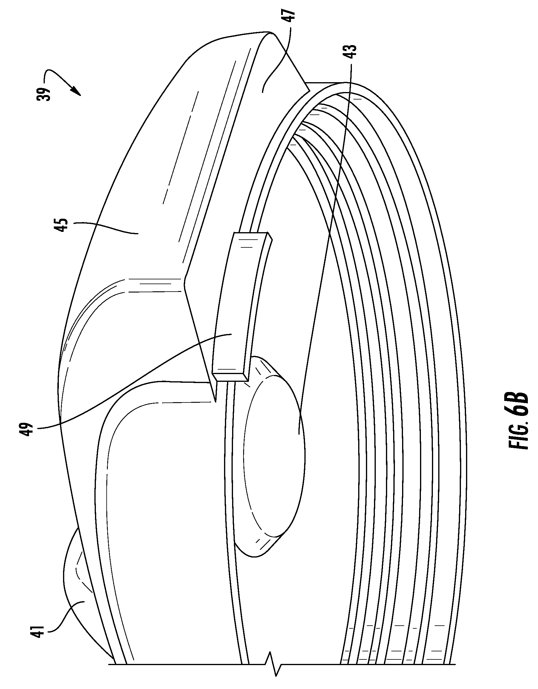
D00013
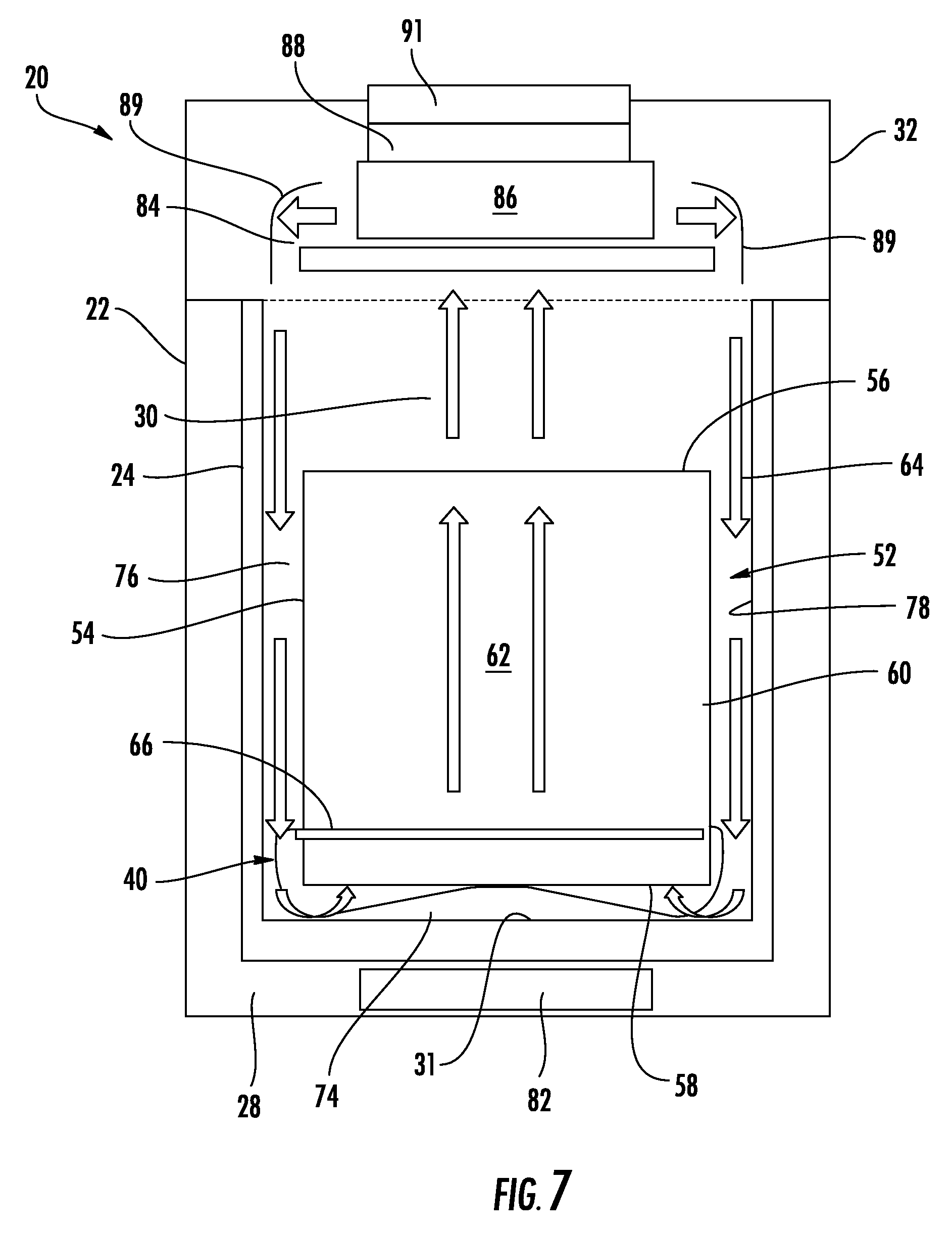
D00014
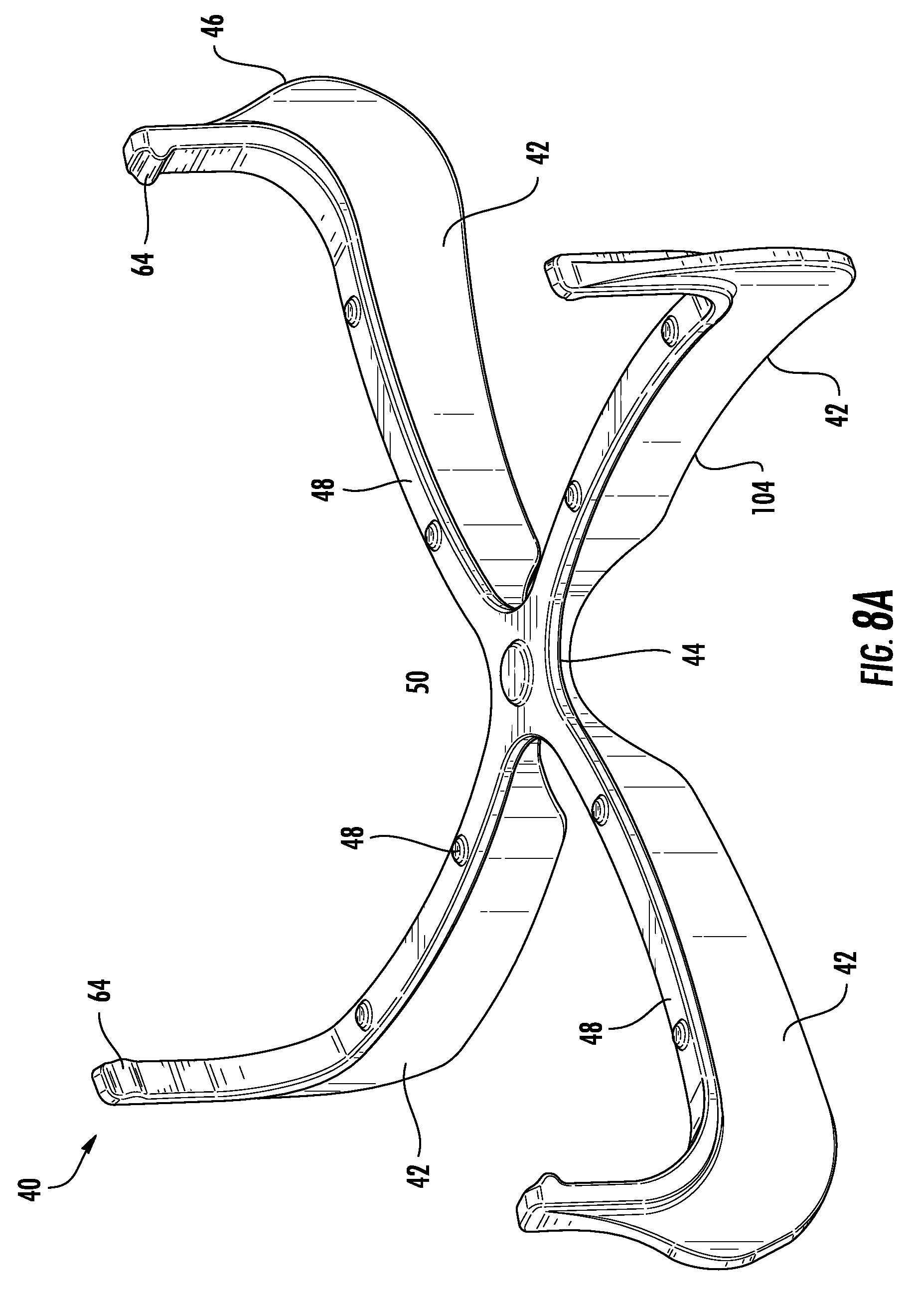
D00015
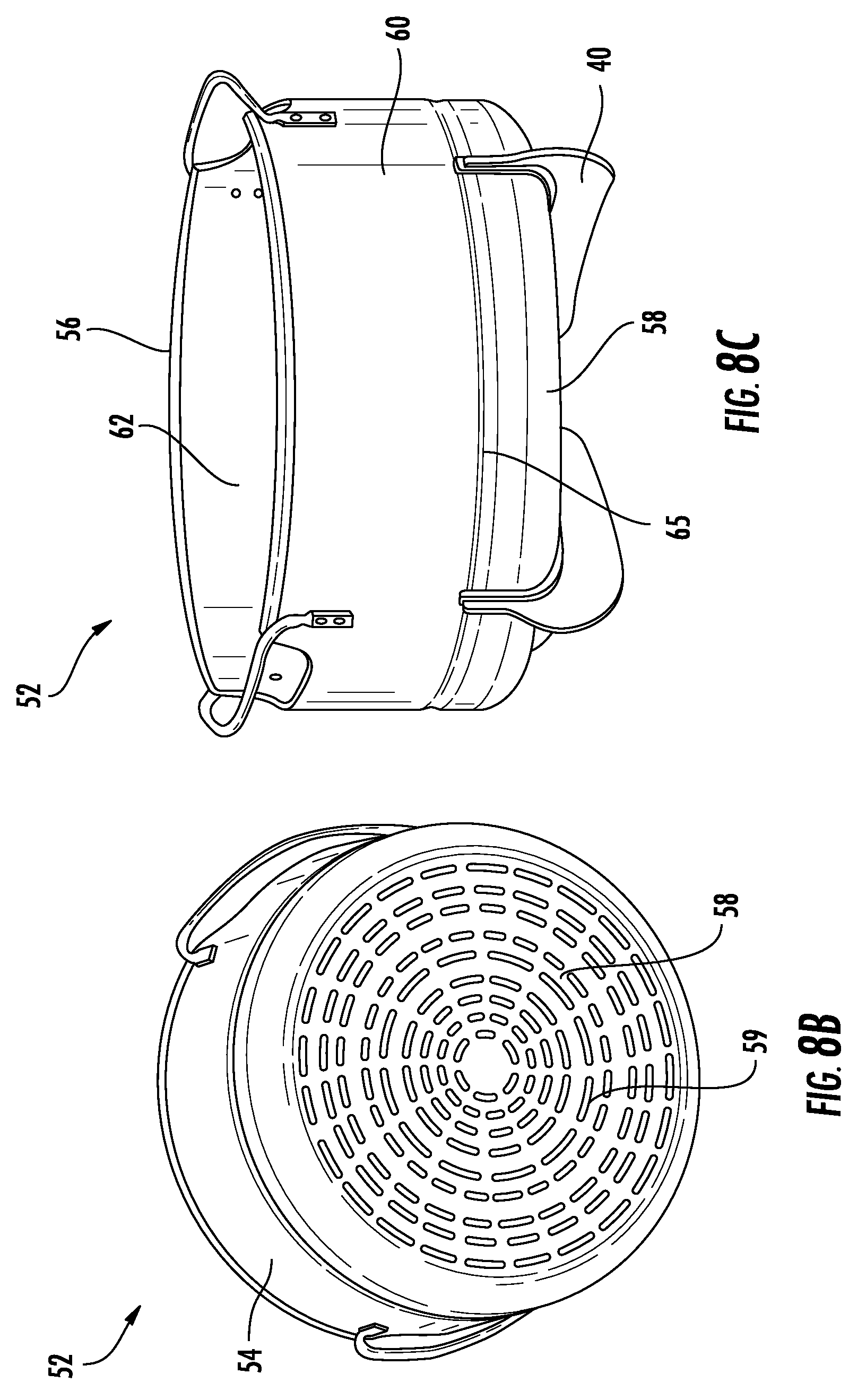
D00016
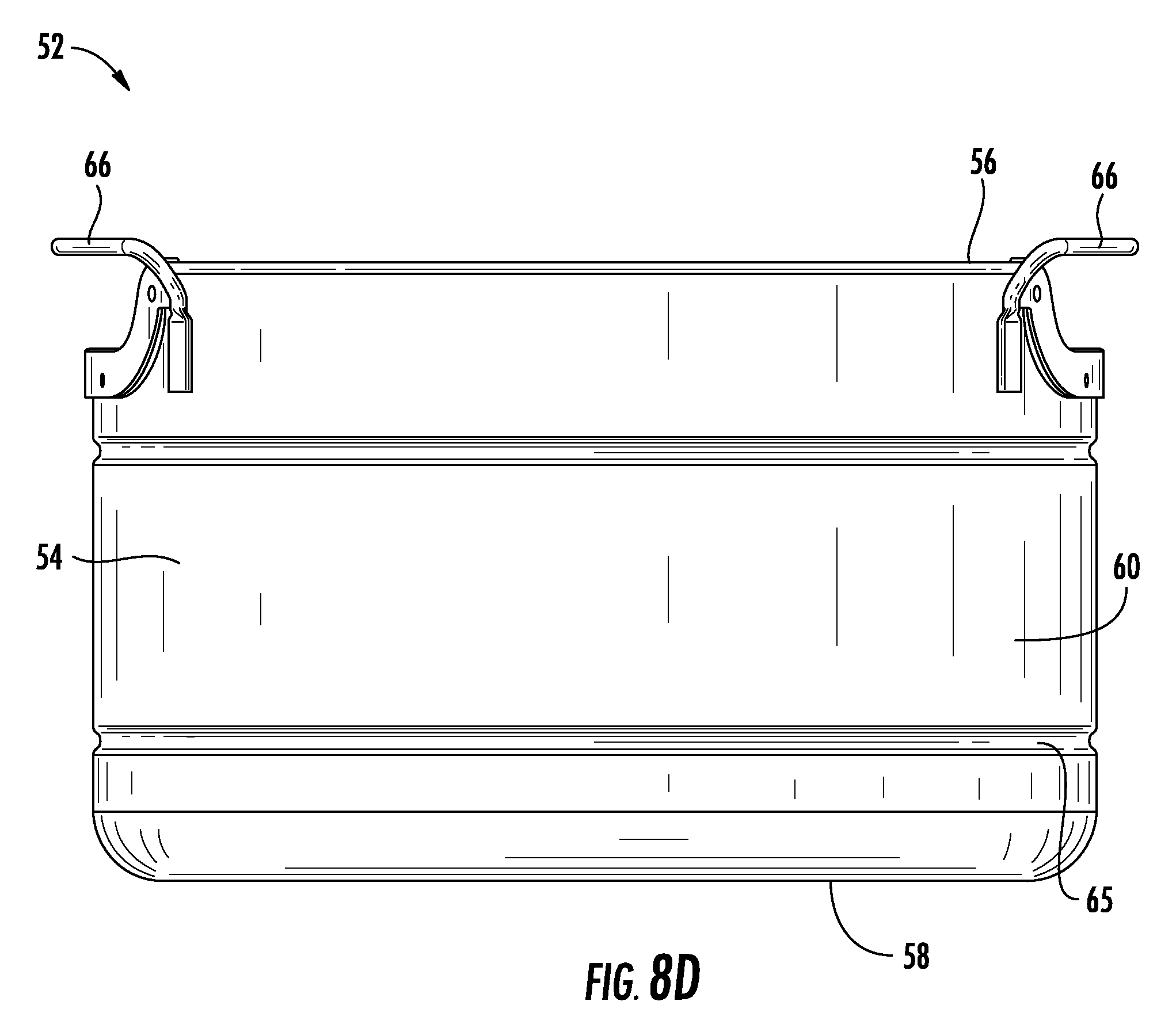
D00017
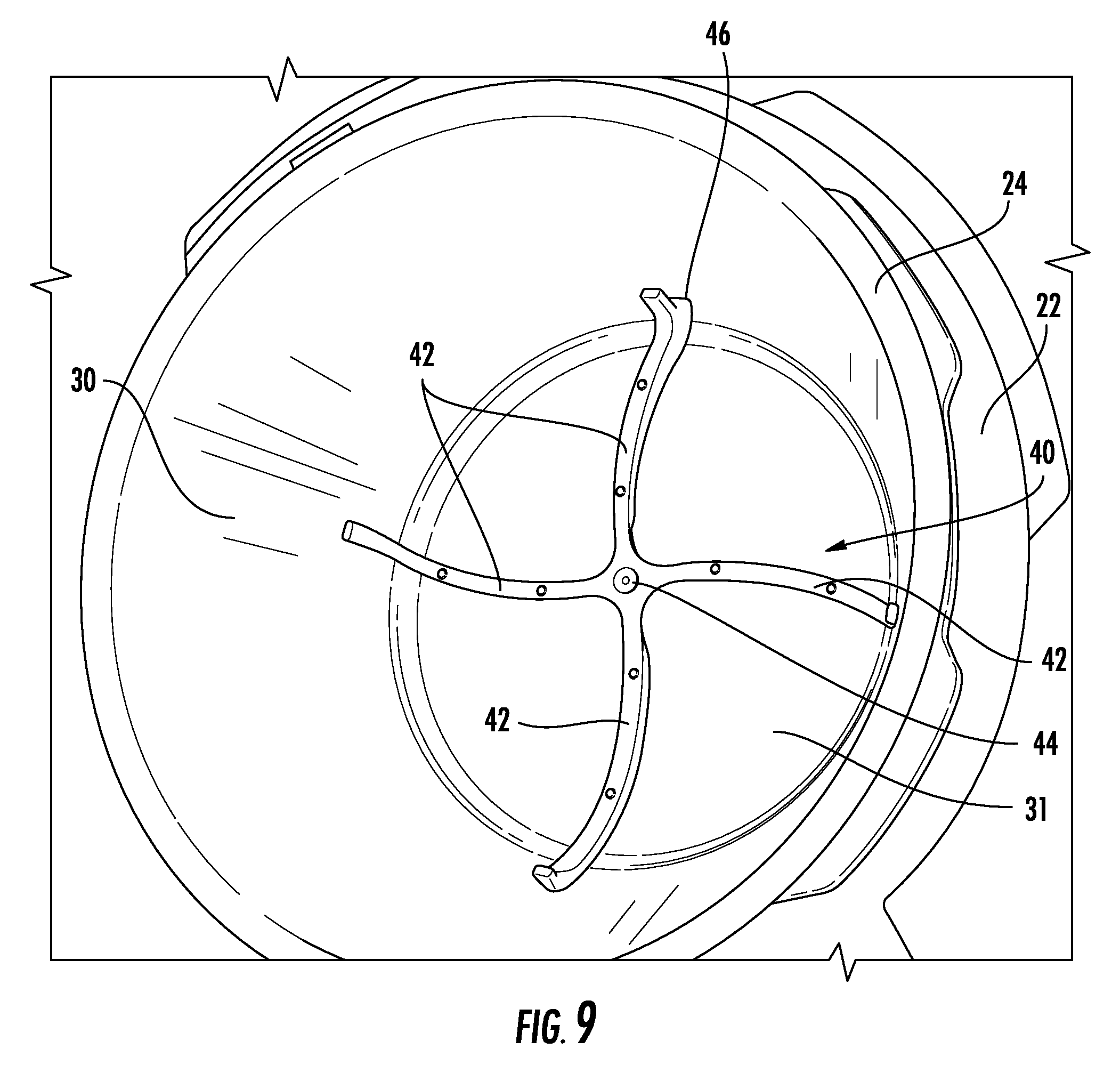
D00018
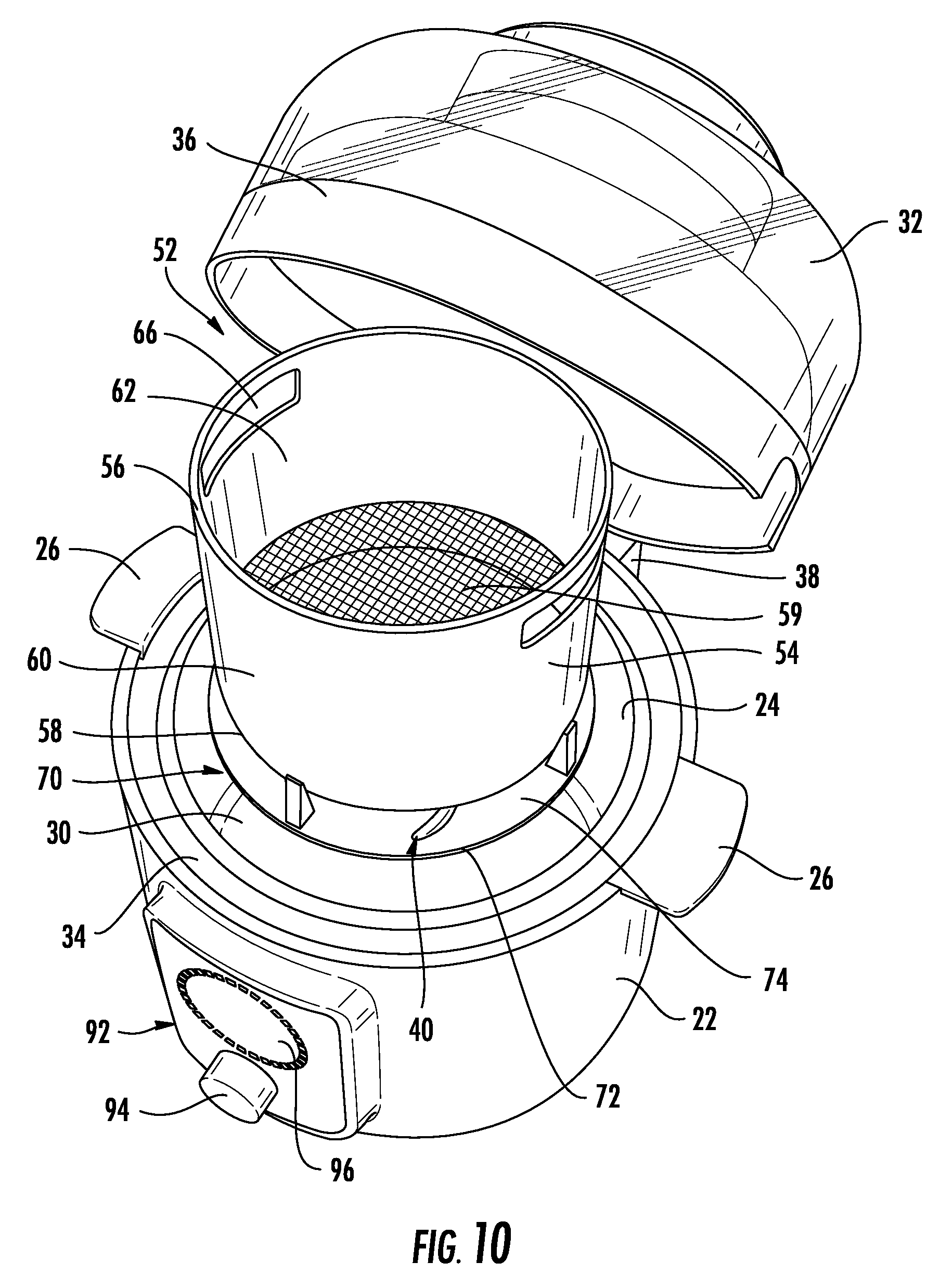
D00019
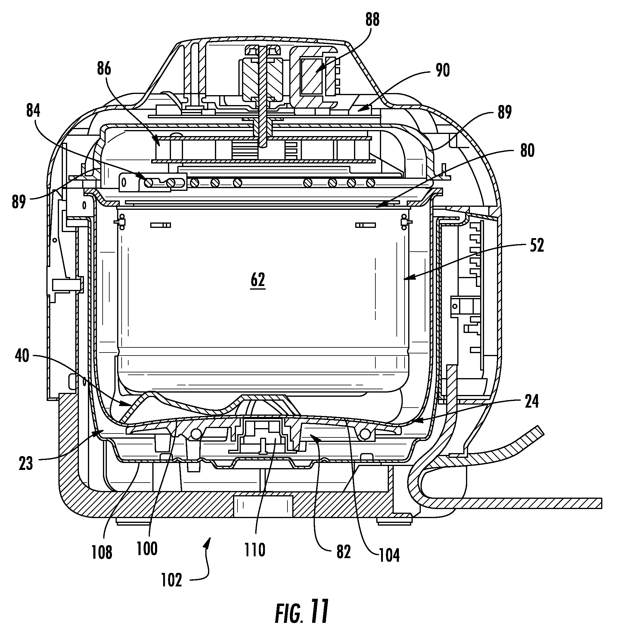
D00020
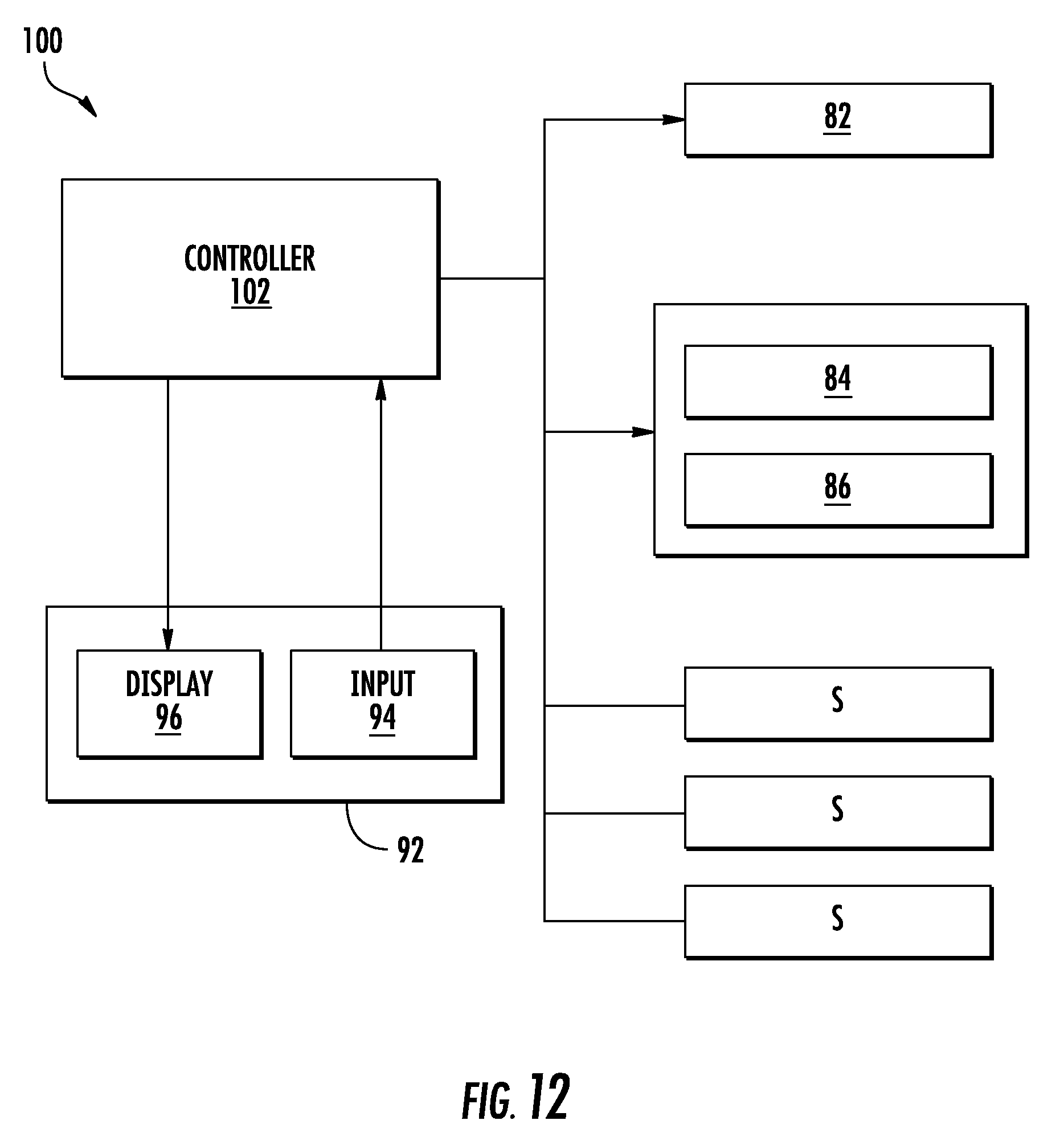
D00021
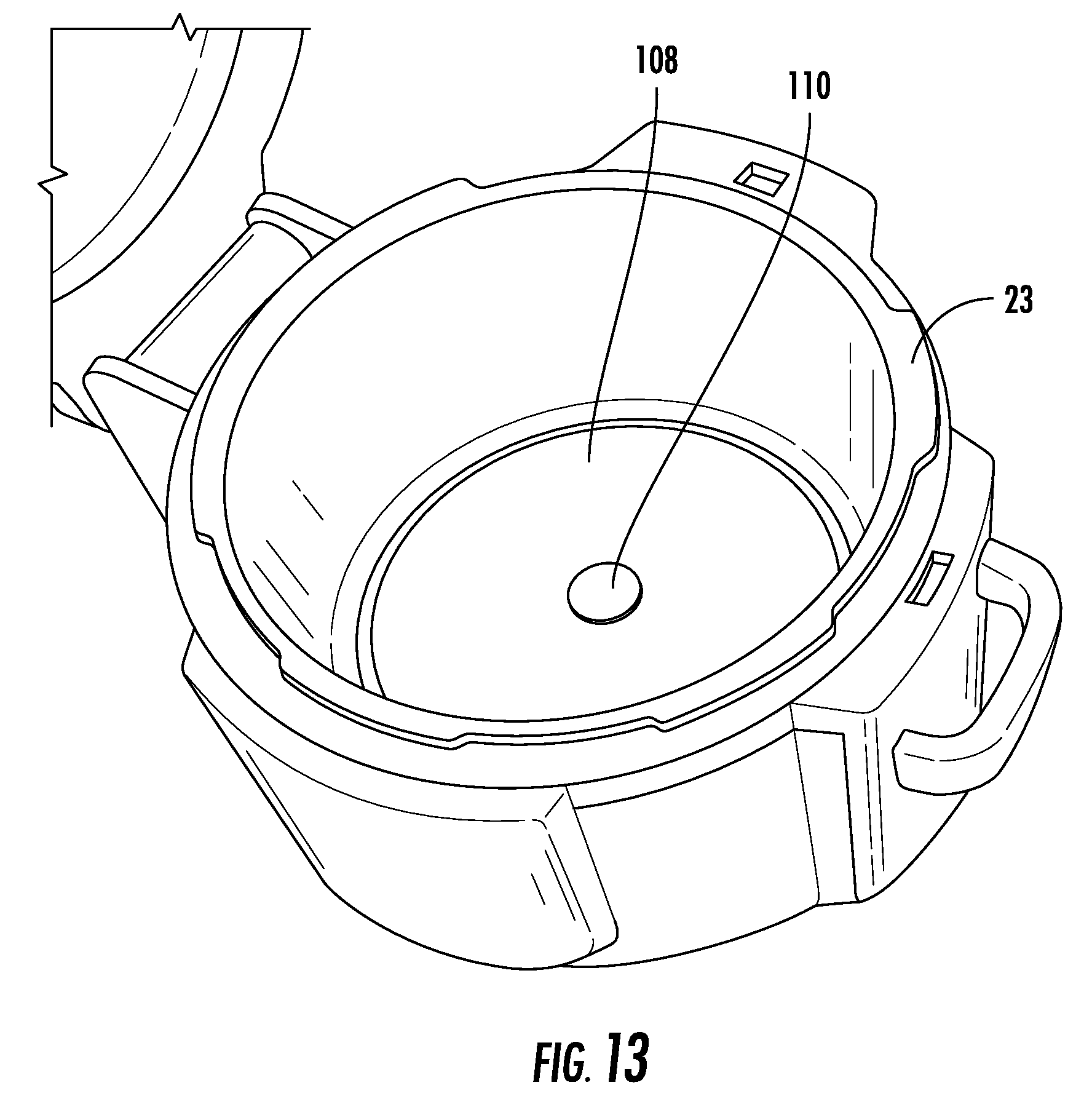
D00022
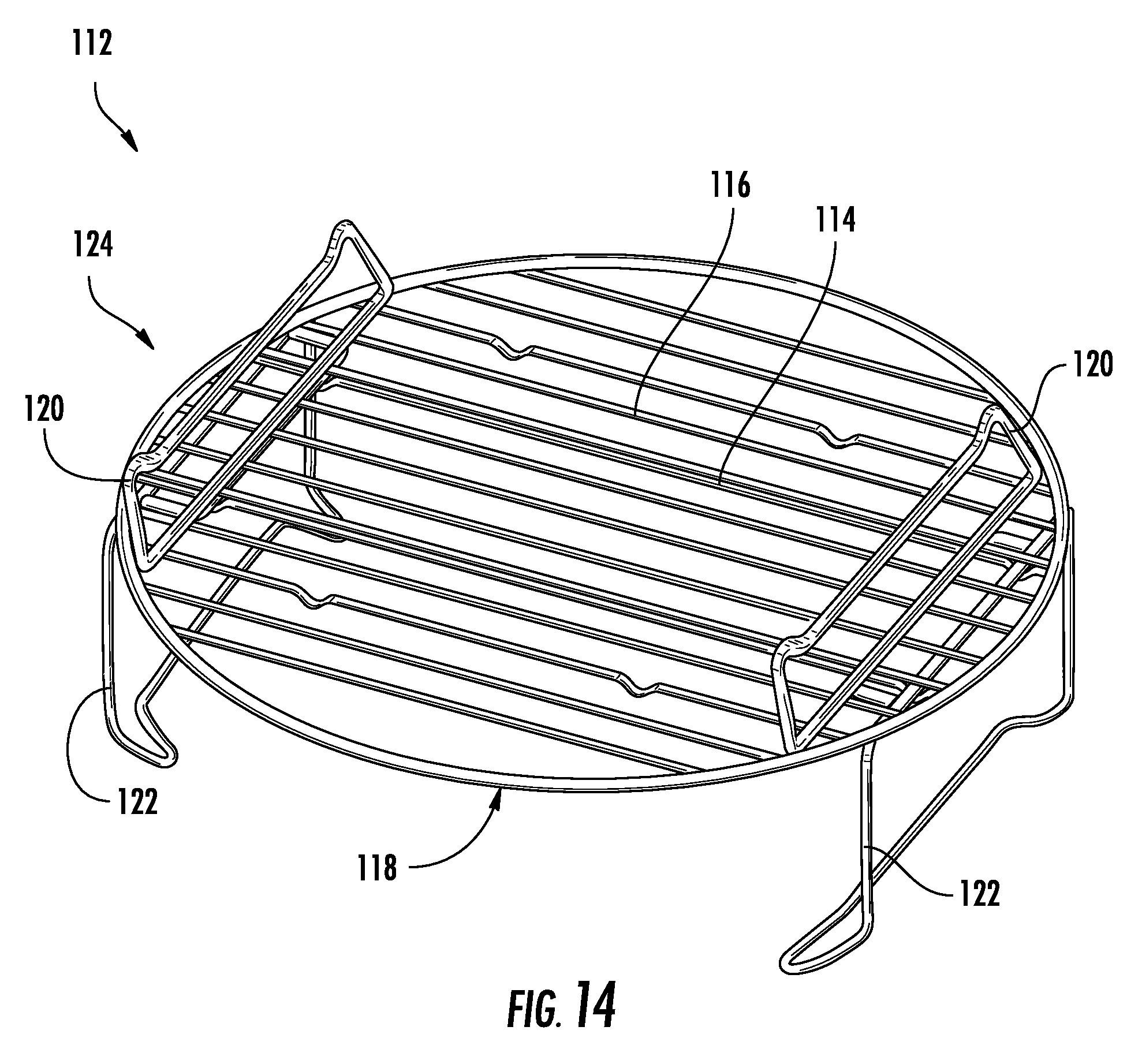
D00023
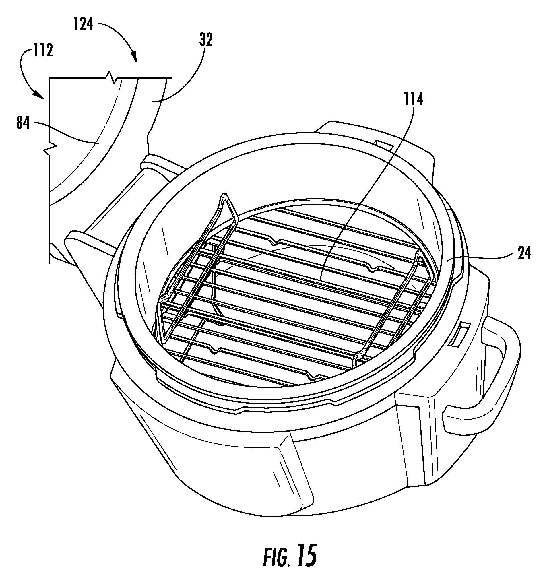
D00024
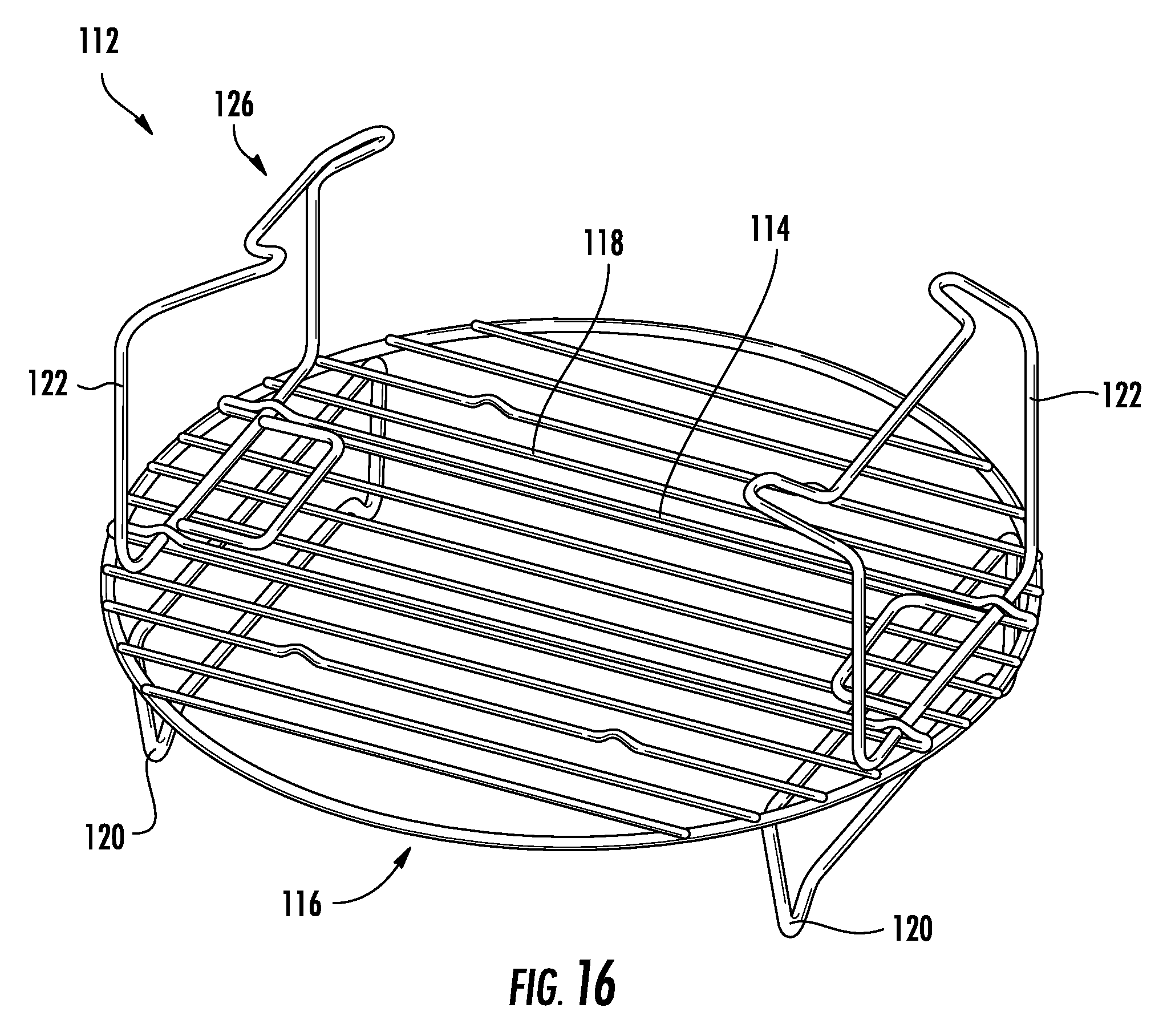
D00025
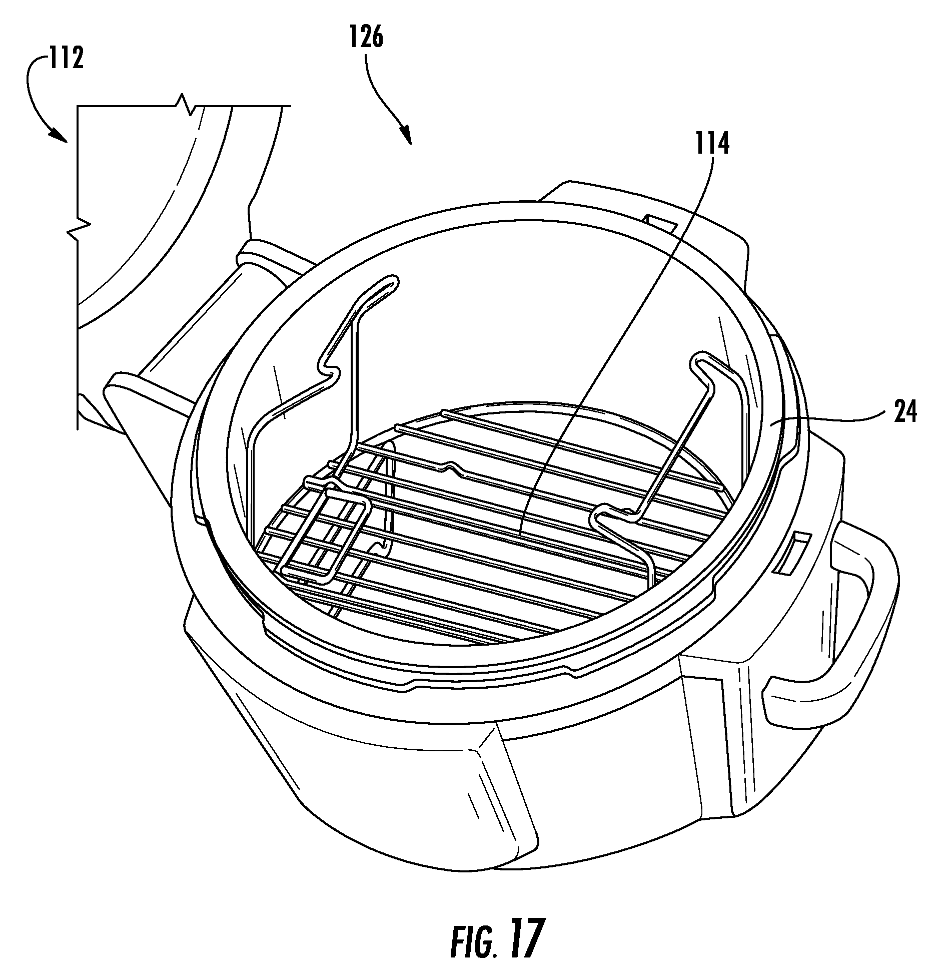
D00026
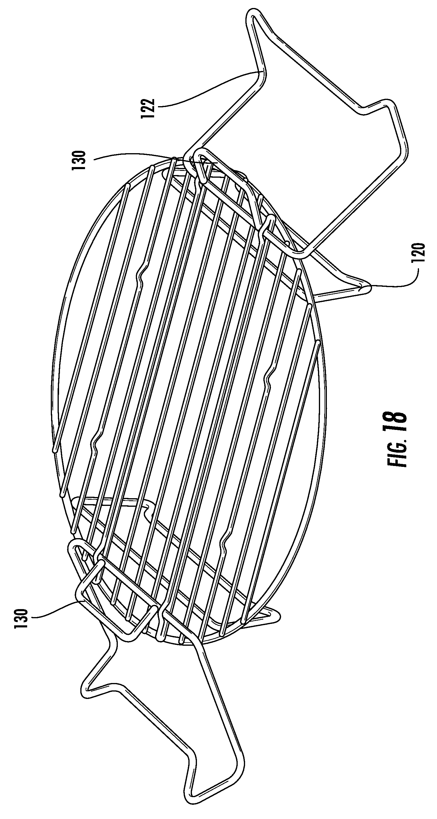
D00027
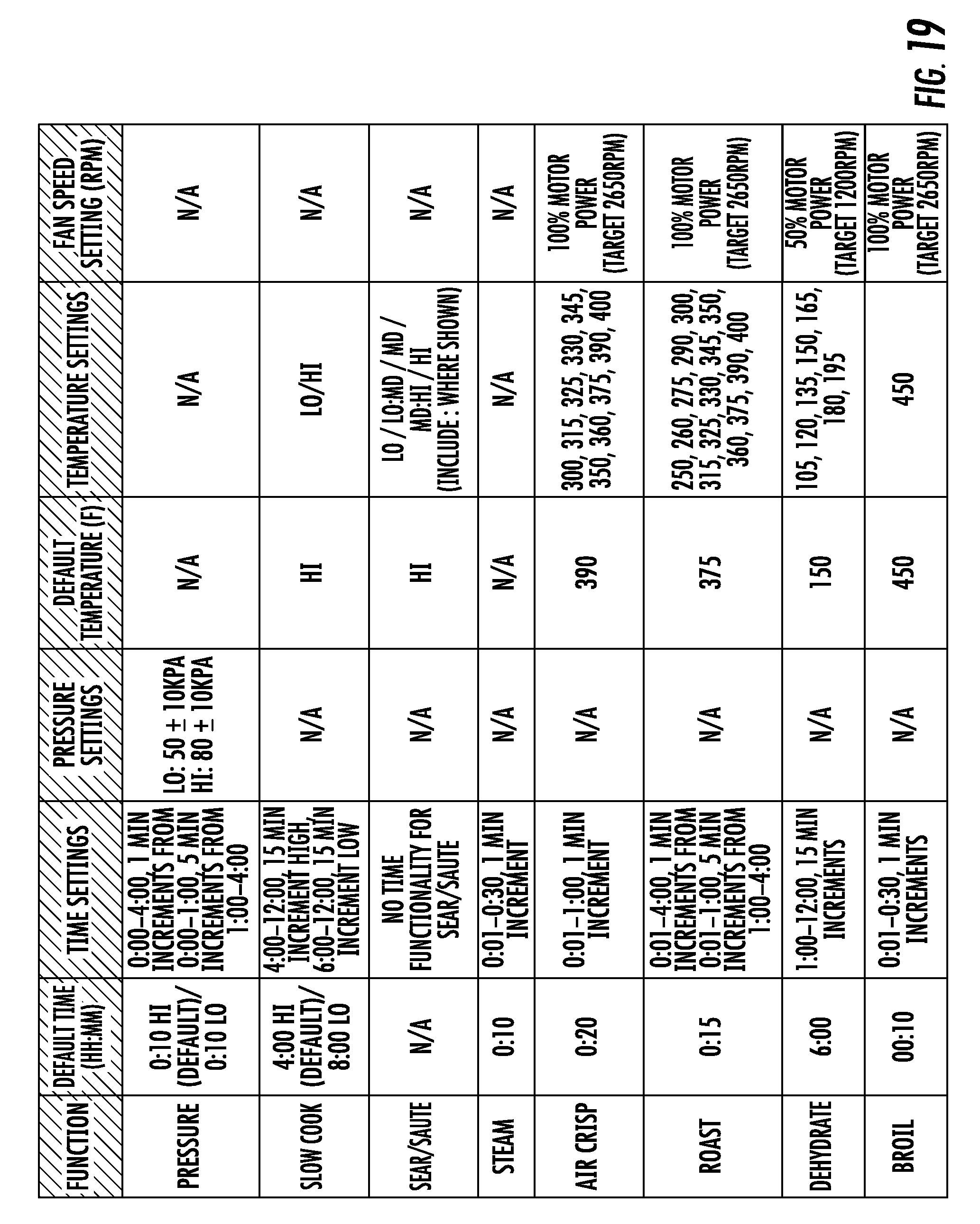
D00028
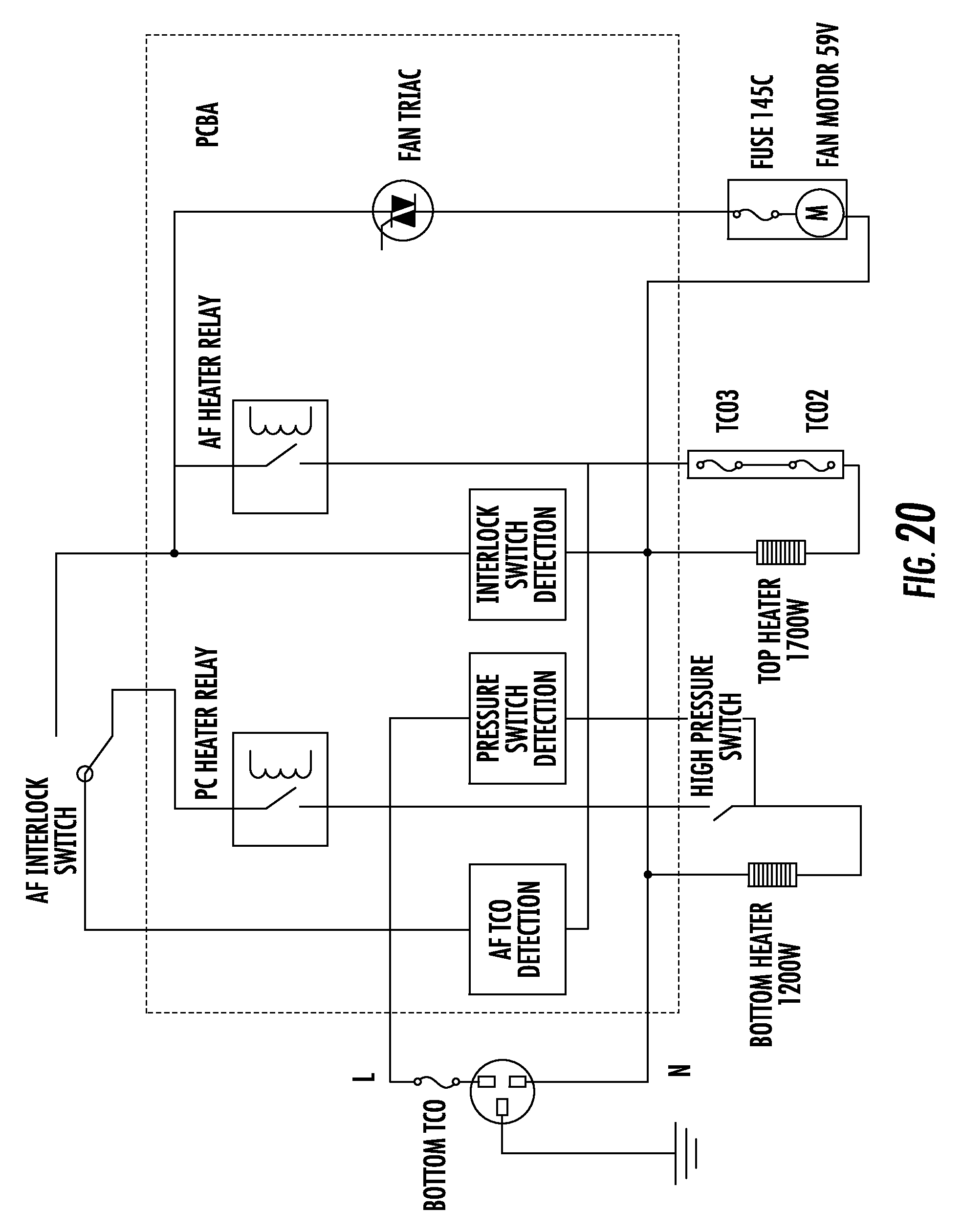
D00029
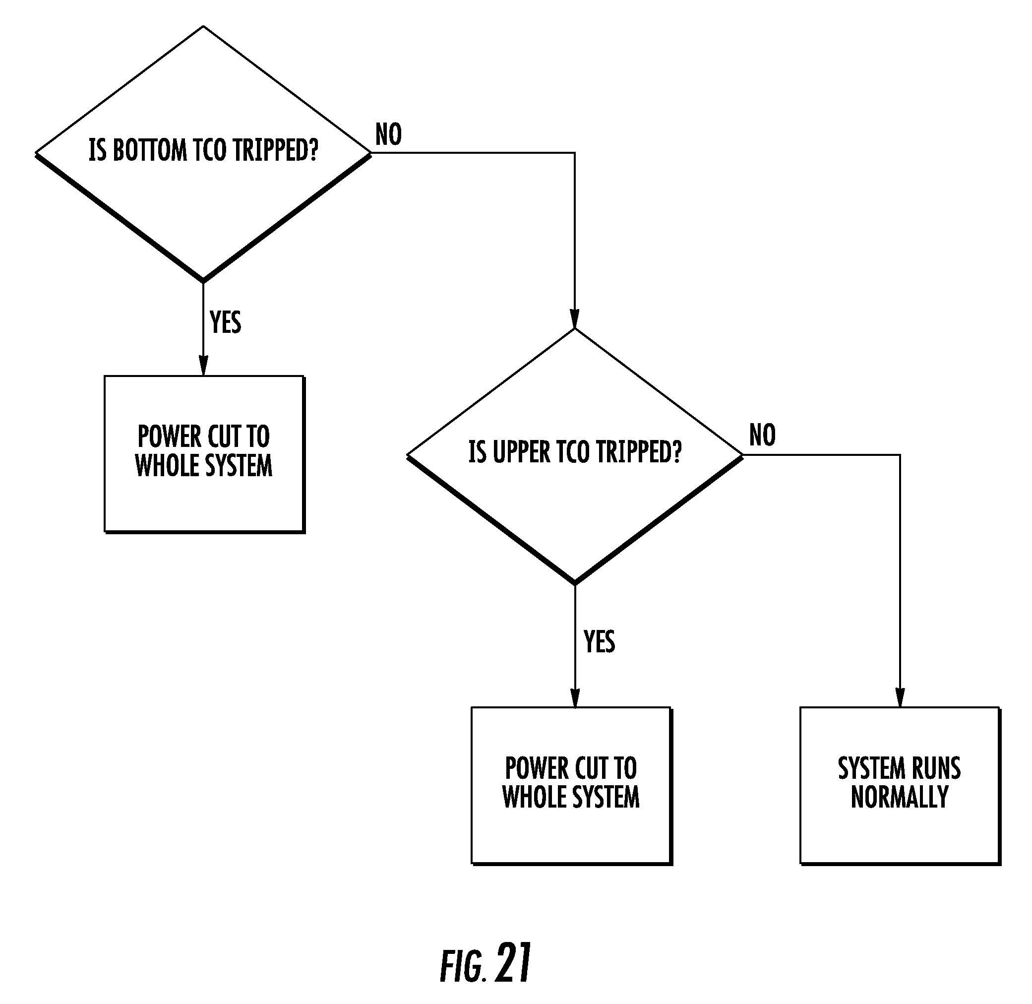
D00030
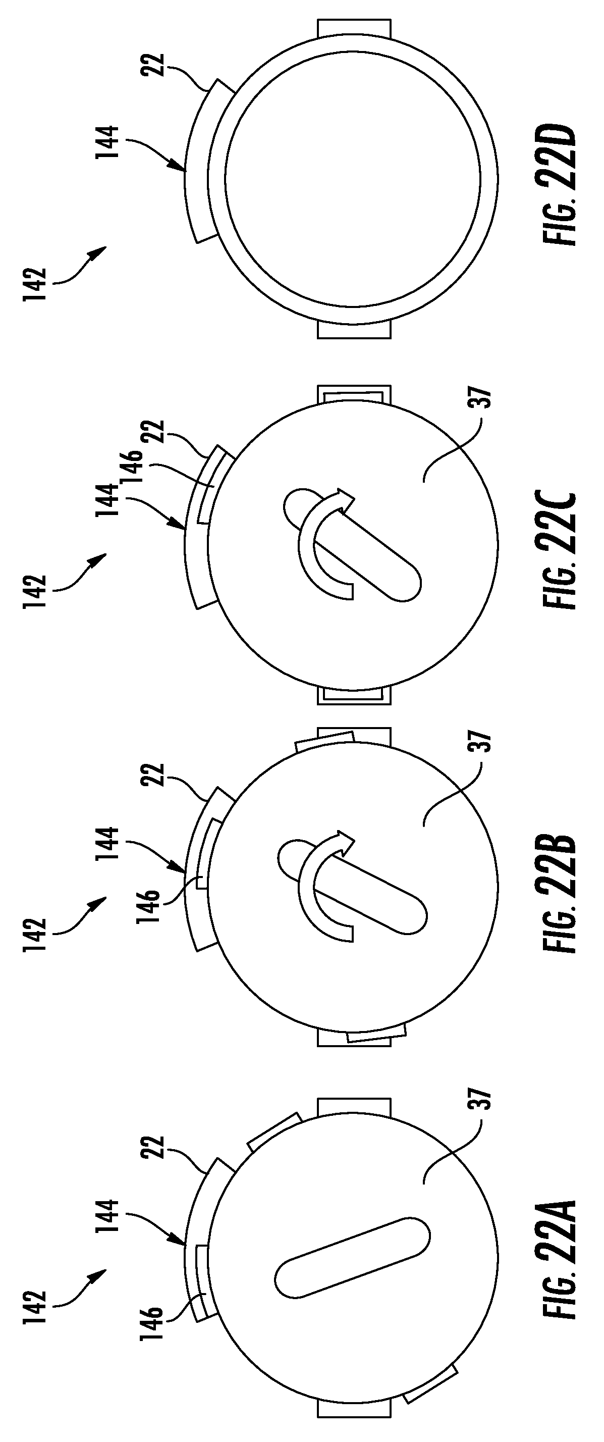
XML
uspto.report is an independent third-party trademark research tool that is not affiliated, endorsed, or sponsored by the United States Patent and Trademark Office (USPTO) or any other governmental organization. The information provided by uspto.report is based on publicly available data at the time of writing and is intended for informational purposes only.
While we strive to provide accurate and up-to-date information, we do not guarantee the accuracy, completeness, reliability, or suitability of the information displayed on this site. The use of this site is at your own risk. Any reliance you place on such information is therefore strictly at your own risk.
All official trademark data, including owner information, should be verified by visiting the official USPTO website at www.uspto.gov. This site is not intended to replace professional legal advice and should not be used as a substitute for consulting with a legal professional who is knowledgeable about trademark law.