Shelving rack having bottom support panel with moveable dividers
Ondrasik Sept
U.S. patent number 10,405,673 [Application Number 15/979,233] was granted by the patent office on 2019-09-10 for shelving rack having bottom support panel with moveable dividers. This patent grant is currently assigned to THE ONDRASIK FAMILY TRUST DATED 11/3/1999. The grantee listed for this patent is THE ONDRASIK FAMILY TRUST DATED 11/3/1999. Invention is credited to V. John Ondrasik.
| United States Patent | 10,405,673 |
| Ondrasik | September 10, 2019 |
Shelving rack having bottom support panel with moveable dividers
Abstract
A shelving rack system, having at least two divider supports extending across the bottom of a base, with a support panel positioned on top of the base, wherein the dividers are positionable from side-to-side to vary the width of the product dispensing channels between the dividers in the shelving rack. Each divider has legs that pass through holes in both the support panel and the divider supports.
| Inventors: | Ondrasik; V. John (Commerce, CA) | ||||||||||
|---|---|---|---|---|---|---|---|---|---|---|---|
| Applicant: |
|
||||||||||
| Assignee: | THE ONDRASIK FAMILY TRUST DATED
11/3/1999 (Commerce, CA) |
||||||||||
| Family ID: | 67844956 | ||||||||||
| Appl. No.: | 15/979,233 | ||||||||||
| Filed: | May 14, 2018 |
| Current U.S. Class: | 1/1 |
| Current CPC Class: | A47F 1/121 (20130101); A47B 57/588 (20130101); A47F 7/28 (20130101); A47F 5/0056 (20130101); A47F 5/005 (20130101); A47B 57/58 (20130101); A47B 96/021 (20130101) |
| Current International Class: | A47F 1/12 (20060101); A47F 5/00 (20060101); A47F 7/28 (20060101); A47F 3/04 (20060101) |
| Field of Search: | ;108/60,61 ;206/561 ;312/35 ;211/184 ;D6/706 |
References Cited [Referenced By]
U.S. Patent Documents
| 936725 | October 1909 | Insinger |
| 1277827 | September 1918 | Barber |
| 2933195 | April 1960 | Radek |
| 3149729 | September 1964 | Smith |
| 3194528 | July 1965 | Chesley |
| 3255987 | June 1966 | Gatch |
| 3269547 | August 1966 | Chamberlin |
| 3301408 | January 1967 | Craine |
| 3385451 | May 1968 | Anderson |
| 3497081 | February 1970 | Field |
| 3501019 | March 1970 | Armstrong |
| 3501020 | March 1970 | Krikorian |
| 3559815 | February 1971 | Huddleston |
| 3601258 | August 1971 | Stein |
| 3608741 | September 1971 | Schray |
| 3750894 | August 1973 | Jensen |
| 3767057 | October 1973 | Holmes |
| 3784027 | January 1974 | Gold |
| 3827574 | August 1974 | Craig, Sr. |
| 4190167 | February 1980 | Wells |
| 4191299 | March 1980 | Moore |
| RE30706 | August 1981 | Bustos |
| 4346806 | August 1982 | Bustos |
| 4437572 | March 1984 | Hoffman |
| 4461388 | July 1984 | Bustos |
| 4589349 | May 1986 | Gebhardt |
| 4750625 | June 1988 | Frederick |
| 4872567 | October 1989 | Bustos |
| 5074420 | December 1991 | Cappel, III |
| 5119945 | June 1992 | Wiggins |
| 5205421 | April 1993 | Bustos |
| 5437380 | August 1995 | Peay |
| 5464105 | November 1995 | Mandeltort |
| 5490600 | February 1996 | Bustos |
| D375860 | November 1996 | Coretti, Jr. |
| 5607068 | March 1997 | Coretti, Jr. |
| 6116436 | September 2000 | Ferrucci |
| 6244447 | June 2001 | Frieze |
| 6299004 | October 2001 | Thalenfeld |
| 6302036 | October 2001 | Carson et al. |
| 6354446 | March 2002 | Chang |
| 6389993 | May 2002 | Ondrasik |
| 6401942 | June 2002 | Eckert |
| 6526897 | March 2003 | Ondrasik |
| 6688240 | February 2004 | Ondrasik |
| 6793223 | September 2004 | Ondrasik et al. |
| 6805250 | October 2004 | Ondrasik |
| 7168711 | January 2007 | Ondrasik |
| 7601312 | October 2009 | Riley |
| 7815060 | October 2010 | Iellimo |
| 7896171 | March 2011 | Battaglia |
| 7950537 | May 2011 | Goodman |
| 8501259 | August 2013 | Vergara |
| 8579121 | November 2013 | Eng |
| 9260126 | February 2016 | Ondrasik |
| 9351590 | May 2016 | Wildrick |
| 9721317 | August 2017 | Alletto, Jr. |
| 2001/0047968 | December 2001 | Wright |
| 2003/0178384 | September 2003 | Speed |
| 2004/0011754 | January 2004 | Zadak |
| 2004/0099619 | May 2004 | Bustos |
| 2004/0256341 | December 2004 | Donnell |
| 2005/0139560 | June 2005 | Whiteside |
| 2005/0161418 | July 2005 | Lynch |
| 2006/0113262 | June 2006 | Knorring, Jr. |
| 2010/0206829 | August 2010 | Clements |
| 2010/0219147 | September 2010 | Moody |
| 2012/0305508 | December 2012 | Brozak |
| 2013/0020270 | January 2013 | Valiulis |
| 2013/0306583 | November 2013 | Caldwell |
| 2014/0103594 | April 2014 | Drummond |
| 2015/0023727 | January 2015 | Williams |
| 2015/0196138 | July 2015 | Juric |
| 2015/0196165 | July 2015 | Iee |
| 2018/0352975 | December 2018 | Alletto |
Assistant Examiner: Barnett; Devin K
Attorney, Agent or Firm: Gordon Rees Scully Mansukhani LLP Heckadon; David R.
Claims
What is claimed is:
1. A shelving rack system, comprising: a wireframe base, wherein the wireframe base comprises a length, a width, a plurality of first parallel bars extending from a back to a front along the length of the wireframe base, and a plurality of second parallel bars extending from a left side to a right side of the wireframe base along the width of the wireframe base, wherein the second parallel bars are perpendicular relative to the first parallel bars; a continuous planar support panel positioned on top of the wireframe base, wherein the support panel substantially covers the wireframe base, wherein the support panel comprises a plurality of holes therein; at least two divider support strips attached to a bottom of the wireframe base and extending substantially the entire width of the wireframe base, wherein each divider support strip is below the wireframe base and each divider support strip has a plurality of apertures therein, wherein each divider support strip is spaced apart from each other; a plurality of dividers positioned on top of the support panel, wherein each divider has at least two legs, and each leg passes both through a corresponding hole from said holes in the support panel and through a corresponding aligned aperture from said apertures in one of the divider support strips from said at least two divider support strips such that the divider legs lock the support panel into a secure position on top of the wireframe base; and wherein the number of divider legs is less than the number of apertures in each divider support strip.
2. The shelving rack system of claim 1, wherein the holes in the support panel are positioned above the apertures in the divider support strips.
3. The shelving rack system of claim 1, wherein the dividers extend in a direction generally parallel to the first parallel bars of the wireframe base.
4. The shelving rack system of claim 1, wherein the dividers extend in a perpendicular direction to the divider support strips.
5. The shelving rack system of claim 1, wherein the dividers are parallel to each other.
6. The shelving rack system of claim 1, wherein the dividers are each individually positionable between a plurality of parallel positions such that a spacing between a corresponding pair of adjacent dividers from said plurality of dividers is adjustable.
7. The shelving rack system of claim 1, further comprising: a front stop spanning across front ends of the dividers.
8. The shelving rack system of claim 7, wherein the front stop is a wire that passes through front brackets of corresponding dividers from said dividers respectively.
9. The shelving rack system of claim 1, further comprising: a front stop passing between adjacent dividers from said plurality of dividers.
10. The shelving rack system of claim 8, wherein each front bracket has openings therein for the front stop to pass therethrough.
Description
TECHNICAL FIELD
The present system relates in general to wire shelving units and in particular to wire shelving units for dispensing products such as milk and beverages from refrigerated store cabinets.
SUMMARY OF THE INVENTION
The present system provides a shelving rack system, comprising: a wireframe base; at least two divider supports extending across the bottom of the wireframe base; a support panel positioned on top of the wireframe base; and a plurality of dividers positioned on top of the support panel, wherein each divider has at least two legs, and each leg passes through a hole in the support panel and down into a hole in one of the divider supports.
The divider supports extend underneath the bottom of the wireframe base from one side of the wireframe base to the other, and the dividers extend from the back to the front of the shelving rack (above the wireframe base). Thus, the divider supports and the dividers are generally perpendicular to one another. This allows the dividers to be supported perpendicularly at many places along their lengths.
The holes in the support panel are positioned above the holes in the divider supports. Placing the legs of the dividers through the holes in the support panel and into the holes in the divider supports holds the dividers in position above the support panel. In addition, placing the legs of the dividers through the holes in the support panel also secures the support panel in position under the products being dispensed. An advantage of the present system is that the dividers are easily moveable side-to-side such that the side-to-side spacing between parallel dividers is adjustable. As such, the dividers can be positioned at various distances apart from one another that correspond to the widths of the products being dispensed. For example, the dividers can be positioned closer together when narrow cans of soda are positioned thereon, or farther apart when wider gallon jugs of milk are to be dispensed.
One advantage of the present shelving rack is the fact that the spacing between the dividers is quickly and easily adjustable. This is due to the fact that there are more sets of aligned holes in the support panel and divider supports than there are dividers being used. As such, the dividers can easily be moved from one position to another.
Another advantage of the present system is that the flat support panel underneath the products being dispensed reduces the total number of wires required in the wire frame below the support panel. This is due to the fact that the products being dispensed are supported by the flat support panel, rather than simply resting on a wire grid. As such, the wires of the wire grid (i.e. wire base) can be positioned farther apart from one another.
Optionally, the present system also includes a back support (such as a wire) spanning across the back ends of the dividers, and optional bottom legs for positioning the support rack in a cabinet. These and other mechanisms for attaching the present system to a cabinet are all contemplated, all keeping within the scope of the present invention.
BRIEF DESCRIPTION OF THE DRAWING
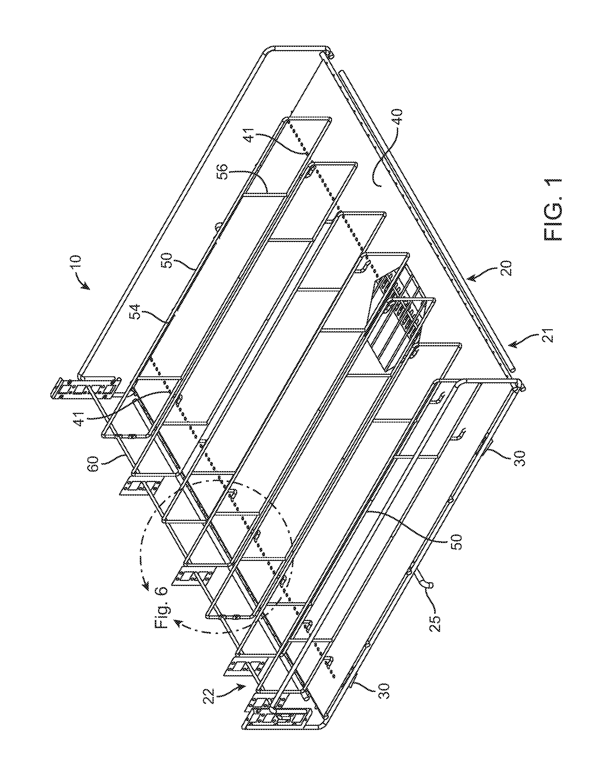
FIG. 1 is a rear perspective view of the present shelving rack system.
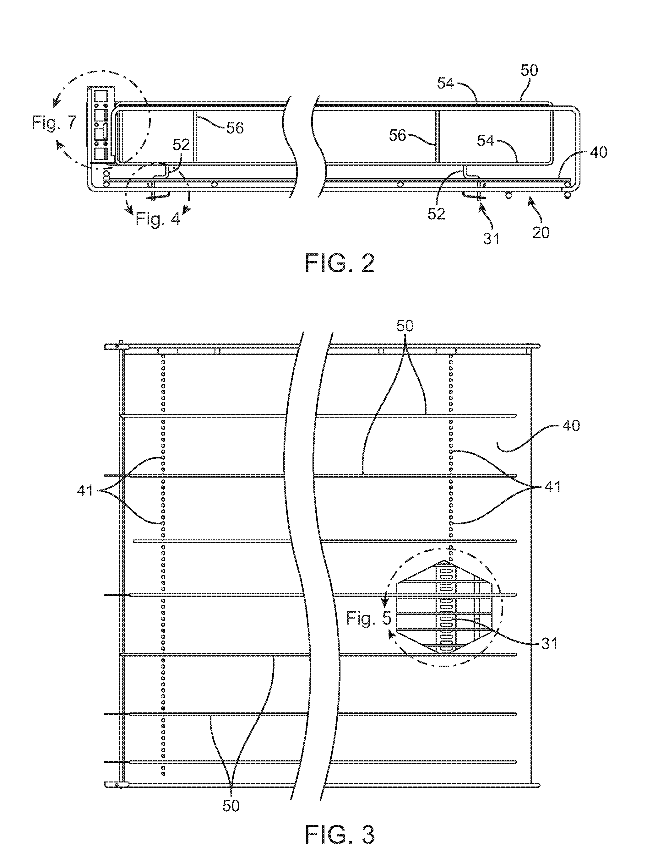
FIG. 2 is a side elevation view of the present shelving rack system.
FIG. 3 is a top plan view of the present shelving rack system.
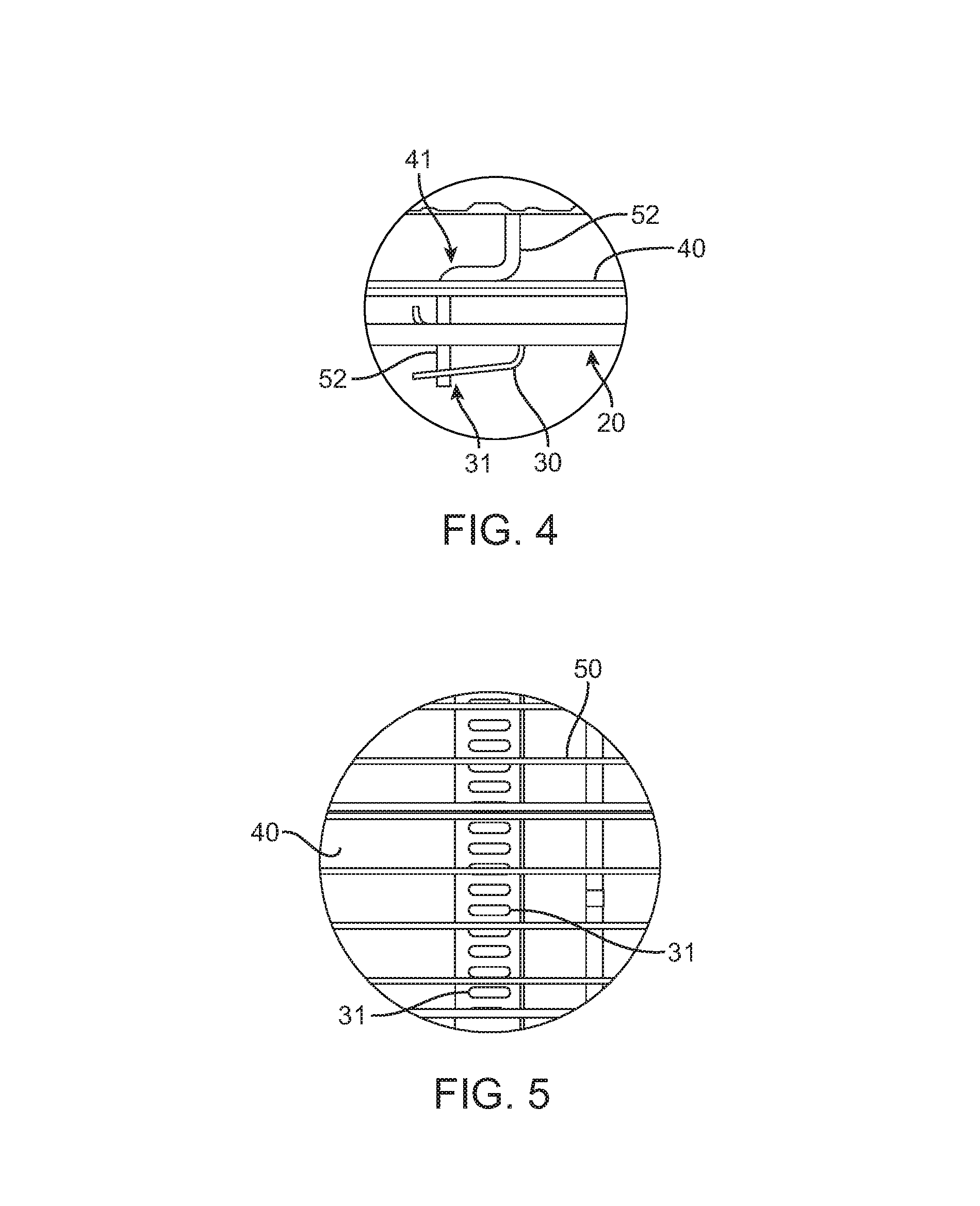
FIG. 4 is a close-up detail view of the leg of the divider passing through the holes in the support panel and through the holes in the divider supports.
FIG. 5 is a close-up top plan view corresponding to FIG. 1, with a section of the support panel removed, showing the wire frame structure therebelow.
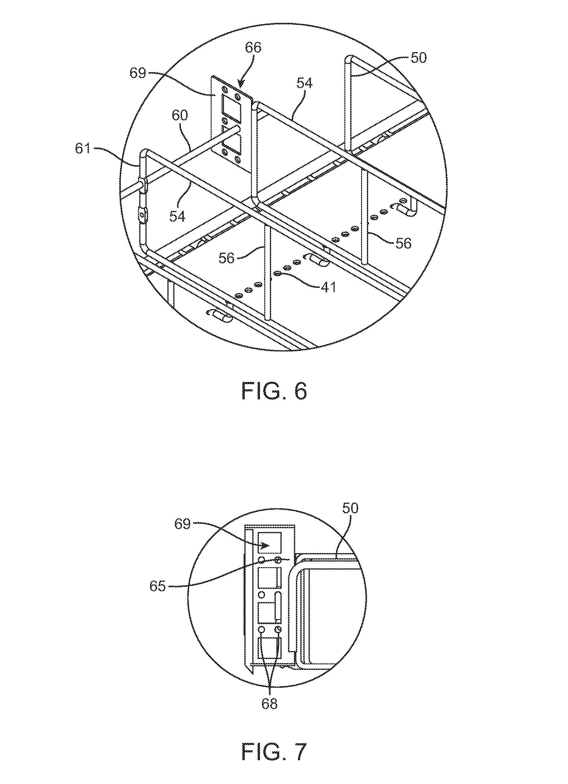
FIG. 6 is a close-up of an optional divider that accepts thick and thin front stops.
FIG. 7 is a close-up of an optional front bracket attached to the present shelving rack system.
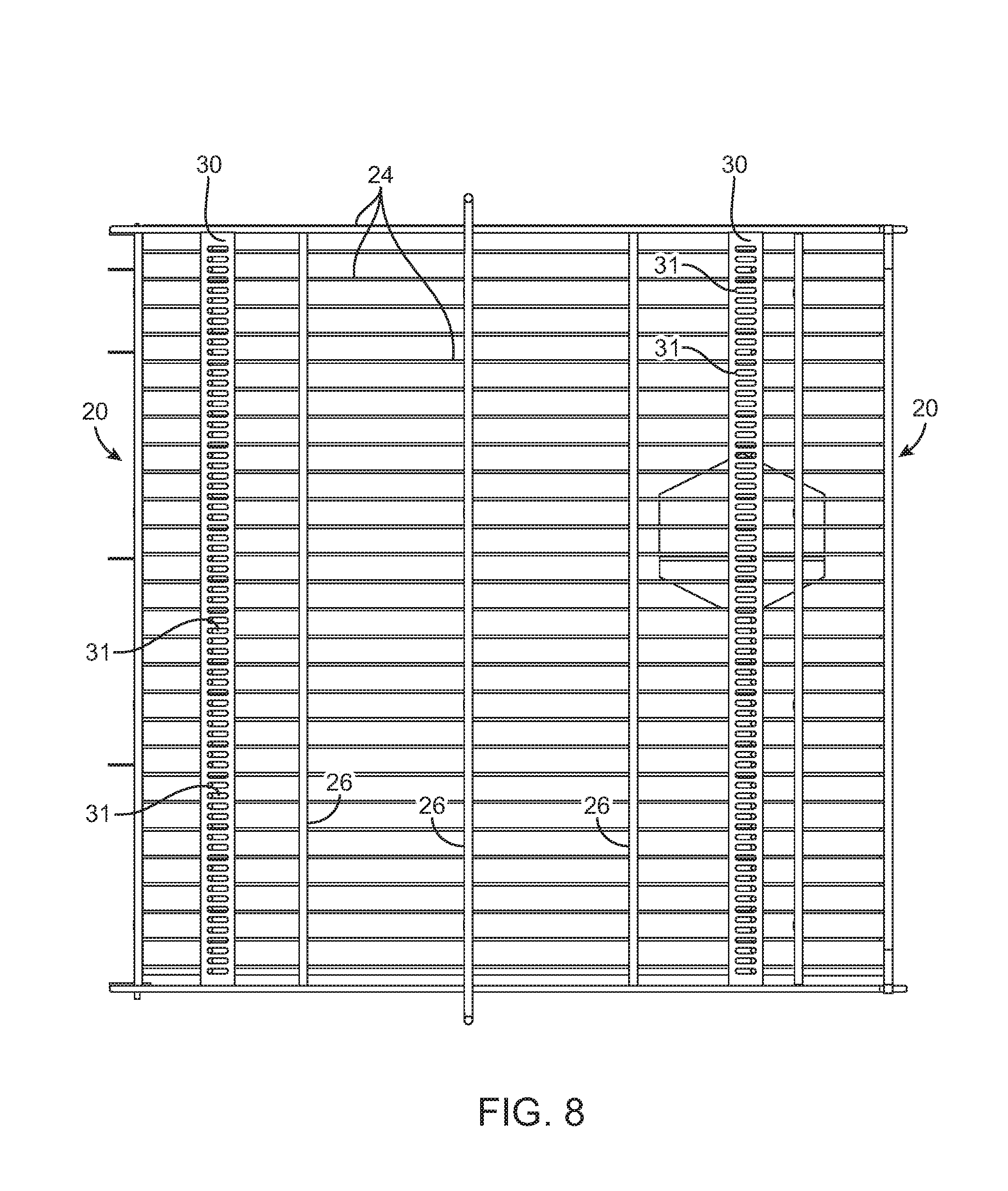
FIG. 8 is a bottom plan view of the present shelving rack system.
DETAILED DESCRIPTION OF THE DRAWING
The present shelving rack system is seen in FIGS. 1 to 3, as follows.
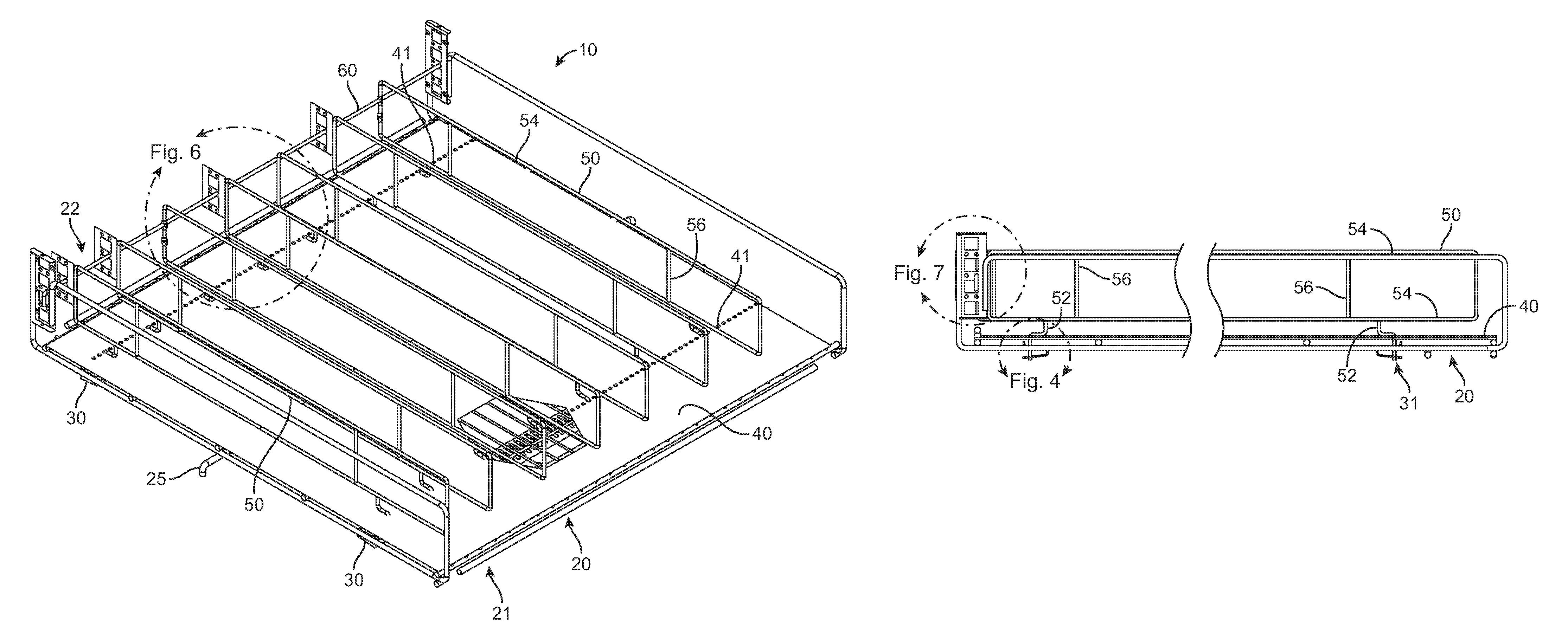
Shelving system 10 comprises: a wireframe base 20; at least two divider supports 30 extending across the bottom of wireframe base 20; a support panel 40 positioned on top of wireframe base 20; and a plurality of dividers 50 positioned on top of support panel 40, wherein each divider 50 has at least two legs 52, and each leg 52 passes through a hole 41 in support panel 40 and also passes down into a hole 31 in one of divider supports 30. In optional embodiments of the present system, support panel 40 is omitted, and product can be placed directly upon wireframe base 20. In further optional embodiments, base 20 is not made of wireframe materials, but is instead made of other suitable materials. As such, the present system is not limited only to wireframe embodiments. As can also be seen, dividers 50 preferably extend from the back 21 to the front 22 of wireframe base 20. Optionally, wireframe base 20 can comprise bottom legs 25 for positioning the support rack in a cabinet.
Preferably, as best seen in FIG. 8, wireframe base 20 comprises both: parallel wireframe bars 24 extending from the back to the front of the wireframe base; and parallel wireframe bars 26 extending from one side of the wireframe base to the other side of the wireframe base.
As seen in the close-up view of FIG. 4, divider supports 30 are positioned below the bottom of wireframe base 20, and holes 41 in support panel 40 are positioned above the holes 31 in the divider supports. As such, legs 52 lock the support panel 40 into a secure position on top of wireframe base 20.
As seen in the close-up view of FIG. 5, divider supports 30 extend from one side of wireframe base 20 to the other side of wireframe base 20. Thus, dividers 50 extend in a perpendicular direction to divider supports 30. Preferably, as best seen in FIG. 2, each divider 50 comprises parallel horizontal bars 54 and optional parallel vertical bars 56 to strengthen the dividers 50 vertically.
As can be appreciated, dividers 50 are individually positionable between a plurality of different parallel side-to-side positions such that the side-to-side spacing between parallel dividers can be adjusted as desired. This re-positioning of individual dividers 50 is done by simply moving legs 51 from one hole 31 to another hole 31 in divider supports 30.
Preferably, the parallel wireframe bars 24 extending from the back to the front of the wireframe base 20 are spaced farther apart than the spacing between dividers 50.
As seen in FIGS. 6 and 7, an optional front stops 60 spans across the front ends of dividers 50. As can be seen, the optional front stop can simply be a wire that passes through divider 50 (at point 61), or a wire that passes through an optional front bracket 65 (at point 66). As seen in FIG. 7, front bracket 65 can optionally have small holes 68 for passing a slender wire therethrough, or larger holes 69 for passing a bar therethrough. Moreover, these various round and square apertures can be positioned at different heights, as illustrated.
* * * * *
D00000
D00001
D00002
D00003
D00004
D00005
XML
uspto.report is an independent third-party trademark research tool that is not affiliated, endorsed, or sponsored by the United States Patent and Trademark Office (USPTO) or any other governmental organization. The information provided by uspto.report is based on publicly available data at the time of writing and is intended for informational purposes only.
While we strive to provide accurate and up-to-date information, we do not guarantee the accuracy, completeness, reliability, or suitability of the information displayed on this site. The use of this site is at your own risk. Any reliance you place on such information is therefore strictly at your own risk.
All official trademark data, including owner information, should be verified by visiting the official USPTO website at www.uspto.gov. This site is not intended to replace professional legal advice and should not be used as a substitute for consulting with a legal professional who is knowledgeable about trademark law.