Implantable pump system having an undulating membrane
Botterbusch , et al. Sep
U.S. patent number 10,398,821 [Application Number 15/976,831] was granted by the patent office on 2019-09-03 for implantable pump system having an undulating membrane. This patent grant is currently assigned to CorWave SA. The grantee listed for this patent is CorWave SA. Invention is credited to Carl N. Botterbusch, Jean-Baptiste Drevet, Adrien Guignabert, Silvere Lucquin, Patrick Meneroud, Pier-Paolo Monticone.


View All Diagrams
| United States Patent | 10,398,821 |
| Botterbusch , et al. | September 3, 2019 |
Implantable pump system having an undulating membrane
Abstract
An implantable pump system is provided, suitable for use as a left ventricular assist device (LVAD) system, having an implantable pump, an extracorporeal battery and a controller coupled to the implantable pump, and a programmer selectively periodically coupled to the controller to configure and adjust operating parameters of the implantable pump. The implantable pump includes a flexible membrane coupled to an actuator assembly that is magnetically engagable with electromagnetic coils, so that when the electromagnetic coils are energized, the actuator assembly causes wavelike undulations to propagate along the flexible membrane to propel blood from through the implantable pump. The controller may be programmed by a programmer to operate at frequencies and duty cycles that mimic physiologic flow rates and pulsatility while operating in an efficient manner that avoids thrombus formation, hemolysis and/or platelet activation.
| Inventors: | Botterbusch; Carl N. (Wyomissing, PA), Lucquin; Silvere (Paris, FR), Monticone; Pier-Paolo (Geneva, CH), Drevet; Jean-Baptiste (Paris, FR), Guignabert; Adrien (Meylan, FR), Meneroud; Patrick (Vif, FR) | ||||||||||
|---|---|---|---|---|---|---|---|---|---|---|---|
| Applicant: |
|
||||||||||
| Assignee: | CorWave SA (Clichy,
FR) |
||||||||||
| Family ID: | 58548780 | ||||||||||
| Appl. No.: | 15/976,831 | ||||||||||
| Filed: | May 10, 2018 |
Prior Publication Data
| Document Identifier | Publication Date | |
|---|---|---|
| US 20180256798 A1 | Sep 13, 2018 | |
Related U.S. Patent Documents
| Application Number | Filing Date | Patent Number | Issue Date | ||
|---|---|---|---|---|---|
| 15484101 | May 15, 2018 | 9968720 | |||
| 62321076 | Apr 11, 2016 | ||||
| Current U.S. Class: | 1/1 |
| Current CPC Class: | A61M 1/1043 (20140204); A61M 1/1005 (20140204); A61M 1/1037 (20130101); A61M 1/122 (20140204); A61M 1/1055 (20140204) |
| Current International Class: | A61M 1/12 (20060101); A61M 1/10 (20060101) |
References Cited [Referenced By]
U.S. Patent Documents
| 2842067 | July 1958 | Stevens |
| 3107630 | October 1963 | Johnson et al. |
| 3165061 | January 1965 | Smith et al. |
| 3608088 | September 1971 | Dorman et al. |
| 3620651 | November 1971 | Hufton |
| 3743446 | July 1973 | Mandroian |
| 3765175 | October 1973 | Ohnaka |
| 4063826 | December 1977 | Riepe |
| 4277706 | July 1981 | Isaacson |
| 4384830 | May 1983 | Wakelin |
| 4484095 | November 1984 | Neumann |
| 4488854 | December 1984 | Miller |
| 4498851 | February 1985 | Kolm et al. |
| 4648807 | March 1987 | Tippetts et al. |
| 4753221 | June 1988 | Kensey et al. |
| 4906229 | March 1990 | Wampler |
| 4931036 | June 1990 | Kanai et al. |
| 4939405 | July 1990 | Okuyama et al. |
| 4955856 | September 1990 | Phillips |
| 4995857 | February 1991 | Arnold |
| 5147388 | September 1992 | Yamazaki |
| 5263978 | November 1993 | Kaufmann et al. |
| 5275580 | January 1994 | Yamazaki |
| 5370509 | December 1994 | Golding et al. |
| 5525041 | June 1996 | Deak |
| 5588812 | December 1996 | Taylor et al. |
| 5982801 | November 1999 | Deak |
| 6058593 | May 2000 | Siess |
| 6079214 | June 2000 | Bishop |
| 6083260 | July 2000 | Aboul-Hosn |
| 6116862 | September 2000 | Rau et al. |
| 6123725 | September 2000 | Aboul-Hosn |
| 6176822 | January 2001 | Nix et al. |
| 6176848 | January 2001 | Rau et al. |
| 6346071 | February 2002 | Mussivand |
| 6361284 | March 2002 | Drevet |
| 6395026 | May 2002 | Aboul-Hosn et al. |
| 6530876 | March 2003 | Spence |
| 6532964 | March 2003 | Aboul-Hosn et al. |
| 6658740 | December 2003 | Habben |
| 6659740 | December 2003 | Drevet |
| 6672847 | January 2004 | Dooley |
| 6723039 | April 2004 | French et al. |
| 6726648 | April 2004 | Kaplon et al. |
| 6732501 | May 2004 | Yu et al. |
| 6811381 | November 2004 | Dooley |
| 6848001 | January 2005 | Sakamoto et al. |
| 6935344 | August 2005 | Aboul-Hosn et al. |
| 6976996 | December 2005 | Aboul-Hosn |
| 7011620 | March 2006 | Siess |
| 7027875 | April 2006 | Siess et al. |
| 7182727 | February 2007 | Aboul-Hosn |
| 7323961 | January 2008 | Drevet |
| 7520850 | April 2009 | Brockway |
| 7696634 | April 2010 | Filardo |
| 7736296 | June 2010 | Siess et al. |
| 7839007 | November 2010 | Filardo |
| 7863768 | January 2011 | Filardo |
| 7889877 | February 2011 | Lutz |
| 8012079 | September 2011 | Delgado, III |
| 8157720 | April 2012 | Marseille et al. |
| 8333686 | December 2012 | Marseille et al. |
| 8343029 | January 2013 | Farnan et al. |
| 8394009 | March 2013 | Bolyard et al. |
| 8394010 | March 2013 | Farnan |
| 8432057 | April 2013 | Filardo |
| 8465410 | June 2013 | Marseille et al. |
| 8512012 | August 2013 | Akdis et al. |
| 8550975 | October 2013 | Foster |
| 8556795 | October 2013 | Bolyard et al. |
| 8585571 | November 2013 | Bachman et al. |
| 8597350 | December 2013 | Rudser et al. |
| 8610304 | December 2013 | Filardo |
| 8714944 | May 2014 | Drevet |
| 8753256 | June 2014 | Bolyard et al. |
| 8784291 | July 2014 | Farnan et al. |
| 8821366 | September 2014 | Farnan et al. |
| 8821527 | September 2014 | Farnan et al. |
| 8827888 | September 2014 | Bolyard et al. |
| 8834136 | September 2014 | Drevet |
| 8852072 | October 2014 | Larose et al. |
| 8870739 | October 2014 | Larose et al. |
| 8956275 | February 2015 | Bolyard et al. |
| 9022916 | May 2015 | Farnan et al. |
| 9080564 | July 2015 | Drevet |
| 9145875 | September 2015 | Filardo |
| 9173984 | November 2015 | Larose et al. |
| 9211367 | December 2015 | Farnan et al. |
| 9308304 | April 2016 | Peters et al. |
| 9446180 | September 2016 | Vadala et al. |
| 9526819 | December 2016 | Chen |
| 9572915 | February 2017 | Heuring et al. |
| 9579437 | February 2017 | Larose et al. |
| 9616158 | April 2017 | Yaghdjian |
| 9694123 | July 2017 | Bourque et al. |
| 9731057 | August 2017 | Garrigue |
| 9744279 | August 2017 | Tamez et al. |
| 9786150 | October 2017 | Kimball et al. |
| 9861728 | January 2018 | Farnan et al. |
| 9956333 | May 2018 | Larose et al. |
| 9968720 | May 2018 | Botterbusch et al. |
| 2001/0001278 | May 2001 | Drevet |
| 2002/0146333 | October 2002 | Drevet |
| 2002/0165426 | November 2002 | Sporer et al. |
| 2003/0002325 | January 2003 | Alvandpour et al. |
| 2005/0261543 | November 2005 | Abe et al. |
| 2006/0155158 | July 2006 | Aboul-Hosn |
| 2007/0299297 | December 2007 | Jarvik |
| 2008/0232987 | September 2008 | Drevet |
| 2009/0082778 | March 2009 | Beane et al. |
| 2010/0241223 | September 2010 | Lee et al. |
| 2011/0124950 | May 2011 | Foster |
| 2011/0176946 | July 2011 | Drevet |
| 2012/0323318 | December 2012 | Yusuf |
| 2013/0078122 | March 2013 | Drevet |
| 2013/0314047 | November 2013 | Eagle et al. |
| 2014/0187852 | July 2014 | Peters et al. |
| 2014/0207232 | July 2014 | Garrigue |
| 2014/0275723 | September 2014 | Fritz et al. |
| 2014/0277423 | September 2014 | Alkhatib et al. |
| 2016/0243294 | August 2016 | Peters et al. |
| 2017/0290966 | October 2017 | Botterbusch et al. |
| 2017/0290967 | October 2017 | Botterbusch et al. |
| 2017/0296723 | October 2017 | Garrigue |
| 2018/0256798 | September 2018 | Botterbusch et al. |
| 2018/0369469 | December 2018 | Le Duc De Lillers et al. |
| 2013203301 | Oct 2015 | AU | |||
| 0 412 856 | Feb 1991 | EP | |||
| 0 415 949 | Mar 1991 | EP | |||
| 0 445 782 | Aug 1994 | EP | |||
| 0 925 081 | Dec 2003 | EP | |||
| 0 961 621 | Jul 2004 | EP | |||
| 1 551 500 | Jul 2005 | EP | |||
| 1 233 797 | Jul 2006 | EP | |||
| 1 337 288 | Mar 2008 | EP | |||
| 1 981 585 | Oct 2008 | EP | |||
| 1 644 639 | Feb 2009 | EP | |||
| 2 152 339 | Feb 2010 | EP | |||
| 2 249 746 | Nov 2010 | EP | |||
| 2 310 067 | Apr 2011 | EP | |||
| 2 600 918 | Jun 2013 | EP | |||
| 2 517 739 | Dec 2013 | EP | |||
| 2 704 761 | Mar 2014 | EP | |||
| 2 753 389 | Jul 2014 | EP | |||
| 2 891 502 | Jul 2015 | EP | |||
| 2 736 552 | Sep 2015 | EP | |||
| 2 164 542 | Aug 2016 | EP | |||
| 2 856 190 | Sep 2016 | EP | |||
| 3 145 558 | Mar 2017 | EP | |||
| 2650862 | Nov 1991 | FR | |||
| 2744769 | Feb 1999 | FR | |||
| 2861910 | Jan 2006 | FR | |||
| 2905147 | Feb 2008 | FR | |||
| 0 662 047 | Nov 1951 | GB | |||
| WO-89/10763 | Nov 1989 | WO | |||
| WO-90/08260 | Jul 1990 | WO | |||
| WO-97/29282 | Aug 1997 | WO | |||
| WO-99/59652 | Nov 1999 | WO | |||
| WO-2007/053881 | May 2007 | WO | |||
| WO-2011/056823 | May 2011 | WO | |||
| WO-2017/087717 | May 2017 | WO | |||
| WO-2017/087785 | May 2017 | WO | |||
Other References
|
US. Appl. No. 15/940,856, filed Mar. 29, 2018, Le Duc De Lillers et al. cited by applicant . U.S. Appl. No. 15/953,269, filed Apr. 13, 2018, Polverelli et al. cited by applicant . International Search Report & Written Opinion dated Jun. 28, 2017 in Int'l PCT Patent Application Serial No. PCT/IB2017/052068. cited by applicant . International Search Report & Written Opinion dated Aug. 22, 2017 in Int'l PCT Patent Application Serial No. PCT/IB2017/052069. cited by applicant . Partial International Search dated Jun. 28, 2017 in Int'l PCT Patent Application Serial No. PCT/IB2017/052069. cited by applicant . Mohite, et al., Does CircuLite Synergy assist device as partial ventricular support have a place in modern management of advanced heart failure?, Expert Rev. Med. Devices, published online Dec. 2, 2014, pp. 1-12. cited by applicant . Ando et al., Electrocardiogram-Synchronized Rotational Speed Change Mode in Rotary Pumps Could Improve Pulsatility, Artificial Organs , 35(10):941-947 (2011). cited by applicant . Bozkurt et al., Improving Arterial Pulsatility by Feedback Control of a Continuous Flow Left Ventricular Assist Device via in silico Modeling, International Journal of Artificial Organs, 37(10):773-785 (2014). cited by applicant . Castellanos et al., Generations of Left Ventricular Assist Devices: The HeartMate Family, Dept. of Bioengineering. Florida Gulf Coast University, BME 3100C, pp. 1-6. cited by applicant . Crow et al., Gastrointestinal Bleeding Rates in Recipients of Nonpulsatile and Pulsatile Left Ventricular Assist Devices, The Journal of Thoracic and Cardiovascular Surgery, 137(1):208-215 (2009). cited by applicant . Fatullayev et al., Continuous-Flow Left Ventricular Assist Device Thrombosis: A Danger Foreseen is a Danger Avoided. Medical Science Monitor Basic Research, 21:141-144 (2015). cited by applicant . Feier et al., A Novel, Valveless Ventricular Assist Device: The Fish Tail Pump. First Experimental in Vivo Studies, Artificial Organs, (26)12:1026-1031 (2002). cited by applicant . Fliess et al., Flatness and Defect of Nonlinear Systems: Introductory Theory and Examples, International Journal of Control, 61(6):1327-1361 (1995). cited by applicant . Fraser et al., A Quantitative Comparison of Mechanical Blood Damage Parameters in Rotary Ventricular Assist Devices: Shear Stress, Exposure Time and Hemolysis Index, Journal of Biomechanical Engineering, 134(8):018002-1 to 018002-11 (2012). cited by applicant . Harris et al., Ventricular Assist Devices, Continuing Education in Anesthesia, Critical Care & Pain, 12(3):145-151 (2012). cited by applicant . International Search Report and Written Opinion dated Aug. 3, 2018 in Int'l PCT Patent Appl. Serial No. PCT/IB2018/052215. cited by applicant . Int'l Search Report & Written Opinion dated Mar. 4, 2019 in Int'l PCT Patent Appl. Serial No. PCT/IB2018/0592199. cited by applicant . Ising, M., RPM and Flow Modulation for a Continuous Flow Left Ventricular Assist Device to Increase Vascular Pulsatility: A Computer Simulation, Mock Circulation, and In-Vivo Animal Study, Electronic Theses and Dissertations, University of Louisville (2011). cited by applicant . Islam et al., Left Ventricular Assist Devices and Gastrointestinal Bleeding: A Narrative Review of Case Reports and Case Series, Clinical Cardiology, 36(4):190-200 (2013). cited by applicant . Jorde et al., Identification and Management of Pump Thrombus in the HeartWare Left Ventricular Assist Device System, JACC: Heart Failure, 3(11):849-856 (2015). cited by applicant . Latham et al., Parameter Estimation and a Series of Nonlinear Observers for the System Dynamics of a Linear Vapor Compressor, IEEE Transactions on Industrial Electronics, 63(11):6736-6744 (2016). cited by applicant . Leverett et al., Red Blood Cell Damage by Shear Stress, Biophysical Journal, 12(3):257-273 (1972). cited by applicant . Malehsa et al., Acquired von Willebrand Syndrome After Exchange of the HeartMate XVE to the HeartMate II Ventricular Assist Device, European Journal of Cardio-Thoracic Surgery, 35(6):1091-1093 (2009). cited by applicant . Mancini et al., Left Ventricular Assist Devices, A Rapidly Evolving Alternative to Transplant, Journal of the American College of Cardiology, 653):2542-2555 (2015). cited by applicant . Mboup et al., Numerical Differentiation With Annihilators in Noisy Environment, Numerical Algorithms, 50(4):439-467 (2009). cited by applicant . Menhour et al., An Efficient Model-Free Setting for Longitudinal and Lateral Vehicle Control: Validation Through the Interconnected Pro-SiVIC/RTMaps Prototyping Platform, IEEE Transactions on Intelligent Transportation Systems, 19(2:461-475 (2018). cited by applicant . Mercorelli, P., A Motion-Sensorless Control for Intake Valves in Combustion Engines, IEEE Transactions on Industrial Electronics, 64(4):3402-3412 (2017). cited by applicant . Mercorelli, P., An Adaptive and Optimized Switching Observer for Sensorless Control of an Electromagnetic Valve Actuator in Camless Internal Combustion Engines, Asian Journal of Control, 16(4):959-973 (2014). cited by applicant . Najjar, et al., An Analysis of Pump Thrombus Events in Patients in HeartWare Advance Bridge to Transplant and Continued Access Protocol Trial, The Journal of Heart and Lung Transplantation, vol. 33(1):23-34 (2014). cited by applicant . Pagani, Francis D., MD, PhD, Department of Cardiac Surgery, University of Michigan, "Technology 101: Review of Current Technologies, Types of Flow, Pump Parameters," American Association for Thoracic Surgery, Annual Meeting (2014), Cardiothoracic Transplant and Mechanical Circulatory Support of Heart and Lung Failure. cited by applicant . Partial International Search dated Jun. 11, 2018 in Int'l PCT Patent Appl. No. PCT/IB18/052215. cited by applicant . Perschall, et al., The Progressive Wave Pump: Numerical Multiphysics Investigation of a Novel Pump Concept With Potential to Ventricular Assist Device Application, Artificial Organs, 35(9):E179-E190 (2012). cited by applicant . Rahman, et al., Position Estimation in Solenoid Actuators, IEEE Transactions on Industry Applications, 32(3):552-559 (1996). cited by applicant . Rigatos, G., "Differential Flatness Theory ad Flatness-Based Control," in Nonlinear Control and Filtering Using Differential Flatness Approaches, vol. 25, Chapter 2, pp. 47-101 (Springer Int'l Publishing 2015). cited by applicant . Wang et al., Rotary Blood Pump Control Strategy for Preventing Left Ventricular Suction, ASAIO Journal, vol. 61, No. 1, pp. 21-30 (2015). cited by applicant . Wang, Quadrotor Analysis and Model Free Control with Comparisons, Universite Paris Sud--Paris XI, (2013). cited by applicant . Weidemann, Daniel, Thesis entitled "Permanent Magnet Reluctance Actuators for Vibration Testing," completed at the Institute of Applied Mechanics, Technische Universitat Munchen, Apr. 2013. cited by applicant . Yuan et al., The Spectrum of Complications Following Left Ventricular Assist Device Placement, Journal of Cardiac Surgery, 27):630-638 (2012). cited by applicant . Zhang et al., Study on Self-Sensor of Linear Moving Magnet Compressor's Piston Stroke, IEEE Sensors Journal, 9(2):154-158 (2009). cited by applicant. |
Primary Examiner: Tejani; Ankit D
Attorney, Agent or Firm: Foley & Lardner LLP Bolten; Christopher C. Pisano; Nicola A.
Parent Case Text
CROSS-REFERENCE TO RELATED APPLICATIONS
This application is a divisional application of U.S. patent application Ser. No. 15/484,101, filed Apr. 10, 2017, now U.S. Pat. No. 9,968,720, which claims the benefit of U.S. Provisional Patent Application No. 62/321,076, filed Apr. 11, 2016, the entire contents of each of which are incorporated herein by reference.
Claims
What is claimed is:
1. A method of pumping blood from a patient's left ventricle to the patient's aorta comprising: delivering blood through an inlet of a housing to a flexible membrane held in tension and rigidly coupled to a magnetic ring; exciting a first electromagnetic coil positioned above the magnetic ring to attract the magnetic ring thereby moving the magnetic ring upward; terminating attraction of the magnetic ring to the first electromagnetic coil by ceasing excitement of the first electromagnetic coil; exciting a second electromagnetic coil positioned below the first electromagnetic coil to the attract the magnetic ring thereby moving the magnetic ring downward; and terminating attraction of the magnetic ring to the second electromagnetic coil by ceasing excitement of the second electromagnetic coil, wherein the upward and downward movement of the magnetic ring translates to upward and downward motion of the flexible membrane thereby propagating a wave along the flexible membrane to propel blood towards an outlet of the housing.
2. The method of pumping blood of claim 1, further comprising selectively varying the excitement of the first and second electromagnetic coils to adjust a rate of the upward and downward movement of the magnetic ring to thereby adjust a rate of the propulsion of blood towards the outlet of the housing.
3. The method of pumping blood of claim 1, wherein the flexible membrane is coupled to the magnetic ring via a rigid ring.
4. The method of pumping blood of claim 1, wherein the housing further comprises one or more suspension rings concentrically disposed around and coupled to the first and second electromagnetic coils and the magnetic ring, the one or more suspension rings configured to permit the upward and downward movement of the magnetic ring.
5. The method of pumping blood of claim 4, wherein the one or more suspension rings exert a spring force on the magnetic ring when the magnetic ring moves upward and downward within the housing.
6. The method of pumping blood of claim 4, wherein the magnetic ring is coupled to each of the flexible membrane and the one or more suspension rings by a plurality of posts.
7. A method of pumping blood from a patient's left ventricle to the patient's aorta, the method comprising: implanting a pump housing comprising an inlet in fluid communication with the left ventricle and an outlet in fluid communication with the aorta, the pump housing containing an actuator system comprising a stationary component and a moving component, and a flexible membrane coupled to the moving component; and sending an electrical signal to the actuator system to cause the stationary component to selectively generate a magnetic field such that the moving component reciprocates at a predetermined frequency and amplitude relative to the stationary component, thereby propagating a wave along the flexible membrane to pump blood at a blood flow rate from the inlet to the outlet.
8. The method of claim 7, wherein the stationary component comprises first and second electromagnetic coils and the moving component comprises a magnet, and wherein the magnetic field is selectively generated by sending the electrical signal to selectively energize the first and second electromagnetic coils, thereby causing the magnet to reciprocate between the first and second electromagnetic coils at the predetermined frequency and amplitude.
9. The method of claim 8, wherein sending the electrical signal to selectively energize the first and second electromagnetic coils comprises: exciting the first electromagnetic coil positioned above the magnet to attract the magnet thereby moving the magnet upward; terminating attraction of the magnet to the first electromagnetic coil by ceasing excitement of the first electromagnetic coil; exciting the second electromagnetic coil positioned below the first electromagnetic coil to the attract the magnet thereby moving the magnet downward; and terminating attraction of the magnet to the second electromagnetic coil by ceasing excitement of the second electromagnetic coil.
10. The method of claim 7, wherein the moving component comprises a magnetic ring concentrically suspended around the stationary component.
11. The method of claim 7, wherein the flexible membrane is coupled to the moving component via a rigid ring.
12. The method of claim 7, wherein the flexible membrane comprises a central aperture such that blood is pumped from the inlet across the flexible membrane through the central aperture and out the outlet.
13. The method of claim 7, wherein the implantable pump housing further comprises one or more suspension rings disposed around and coupled to the stationary component and the moving component, the one or more suspension rings configured to permit the moving component to reciprocate relative to the stationary component.
14. The method of claim 13, wherein the one or more suspension rings exert a spring force on the moving component when the moving component reciprocates relative to the stationary component.
15. The method of claim 13, wherein the moving component is coupled to each of the flexible membrane and the one or more suspension rings by a plurality of posts.
16. The method of claim 7, wherein the pump housing comprises a delivery channel formed between the actuator system and an interior surface of the pump housing adjacent the inlet, and a flow channel formed between a bottom surface of the actuator system and an interior portion of the pump housing adjacent the outlet, the flow channel having the flexible membrane suspended therein such that the flexible membrane pumps the blood from the inlet through the delivery channel and across the flexible membrane within the flow channel to the outlet.
17. The method of claim 7, further comprising selectively varying the magnetic field to thereby adjust the blood flow rate from the inlet to the outlet.
18. The method of claim 7, wherein sending the electrical signal to the actuator system to cause the stationary component to selectively generate a magnetic field comprises sending the electrical signal from a controller operatively coupled to the actuator system.
19. The method of claim 18, wherein the controller is percutaneously coupled to the pump housing.
20. The method of claim 18, further comprising energizing the controller via an extracorporeal battery.
Description
FIELD OF THE INVENTION
The present invention relates generally to heart pumps and more particularly to implantable pumps having an undulating membrane designed to reduce hemolysis and platelet activation.
BACKGROUND
The human heart is comprised of four major chambers with two ventricles and two atria. Generally, the right-side heart receives oxygen-poor blood from the body into the right atrium and pumps it via the right ventricle to the lungs. The left-side heart receives oxygen-rich blood from the lungs into the left atrium and pumps it via the left ventricle to the aorta for distribution throughout the body. Due to any of a number of illnesses, including coronary artery disease, high blood pressure (hypertension), valvular regurgitation and calcification, damage to the heart muscle as a result of infarction or ischemia, myocarditis, congenital heart defects, abnormal heart rhythms or various infectious diseases, the left ventricle may be rendered less effective and thus unable to pump oxygenated blood throughout the body.
The Centers for Disease Control and Prevention (CDC) estimate that about 5.1 million people in the United States suffer from some form of heart failure. Heart failure is generally categorized into four different stages with the most severe being end stage heart failure. End stage heart failure may be diagnosed where a patient has heart failure symptoms at rest in spite of medical treatment. Patients at this stage may have systolic heart failure, characterized by decreasing ejection fraction. In patients with systolic heart failure, the walls of the ventricle, which are typically thick in a healthy patient, become thin and weak. Consequently, during systole a reduced volume of oxygenated blood is ejected into circulation, a situation that continues in a downward spiral until death. A patient diagnosed with end stage heart failure has a one-year mortality rate of approximately 50%.
For patients that have reached end stage heart failure, treatment options are limited. In addition to continued use of drug therapy commonly prescribed during earlier stages of heart failure, the typical recommend is cardiac transplantation and implantation of a mechanical assist device. While a cardiac transplant may significantly prolong the patient's life beyond the one year mortality rate, patients frequently expire while on a waitlist for months and sometimes years awaiting a suitable donor heart. Presently, the only alternative to a cardiac transplant is a mechanical implant. While in recent years mechanical implants have improved in design, typically such implants will prolong a patient's life by a few years at most, and include a number of co-morbidities.
One type of mechanical implant often used for patients with end stage heart failure is a left ventricular assist device (LVAD). The LVAD is a surgically implanted pump that draws oxygenated blood from the left ventricle and pumps it directly to the aorta, thereby off-loading (reducing) the pumping work of the left ventricle. LVADs typically are used either as "bridge-to-transplant therapy" or "destination therapy." When used for bridge-to-transplant therapy, the LVAD is used to prolong the life of a patient who is waiting for a heart transplant. When a patient is not suitable for a heart transplant, the LVAD may be used as a destination therapy to prolong the life, or improve the quality of life, of the patient, but generally such prolongation is for only a couple years.
Generally, a LVAD includes an inlet cannula, a pump, and an outlet cannula, and is coupled to an extracorporeal battery and control unit. The inlet cannula typically directly connected to the left ventricle, e.g., at the apex, and delivers blood from the left ventricle to the pump. The outlet cannula typically connected to the aorta distal to the aortic valve, delivers blood from the pump to the aorta. Typically, the outlet cannula of the pump is extended using a hose-type structure, such as a Dacron graft, to reach a proper delivery location on the aorta. Early LVAD designs were of the reciprocating type but more recently rotary and centrifugal pumps have been used.
U.S. Pat. No. 4,277,706 to Isaacson, entitled "Actuator for Heart Pump," describes a LVAD having a reciprocating pump. The pump described in the Isaacson patent includes a housing having an inlet and an outlet, a cavity in the interior of the pump connected to the inlet and the outlet, a flexible diaphragm that extends across the cavity, a plate secured to the diaphragm, and a ball screw that is configured to be reciprocated to drive the plate and connected diaphragm from one end of the cavity to the other end to simulate systole and diastole. The ball screw is actuated by a direct current motor. The Isaacson patent also describes a controller configured to manage the revolutions of the ball screw to control the starting, stopping and reversal of directions to control blood flow in and out of the pump.
Previously-known reciprocating pump LVADs have a number of drawbacks. Such pumps often are bulky, heavy and may require removal of bones and tissue in the chest for implantation. They also require a significant amount of energy to displace the blood by compressing the cavity. Moreover, the pump subjects the blood to significant pressure fluctuations as it passes through the pump, resulting in high shear forces and risk of hemolysis. These pressure fluctuations may be exaggerated at higher blood flow rates. Further, depending on the geometry of the pump, areas of little or no flow may result in flow stagnation, which can lead to thrombus formation and potentially fatal medical conditions, such as stroke. Finally, the positive displacement pumps like the one described in the Isaacson patent are incapable of achieving pulsatility similar to that of the natural heart, e.g., roughly 60 to 100 beats per minute, while maintaining physiological pressure gradients.
LVADs utilizing rotary and centrifugal configurations also are known. For example, U.S. Pat. No. 3,608,088 to Reich, entitled "Implantable Blood Pump," describes a centrifugal pump to assist a failing heart. The Reich patent describes a centrifugal pump having an inlet connected to a rigid cannula that is coupled to the left ventricular cavity and a Dacron graft extending from the pump diffuser to the aorta. A pump includes an impeller that is rotated at high speeds to accelerate blood, and simulated pulsations of the natural heart by changing rotation speeds or introducing a fluid oscillator.
U.S. Pat. No. 5,370,509 to Golding, entitled "Sealless Rotodynamic Pump with Fluid Bearing," describes an axial blood pump capable for use as a heart pump. One embodiment described involves an axial flow blood pump with impeller blades that are aligned with the axes of the blood inlet and blood outlet. U.S. Pat. No. 5,588,812 to Taylor, entitled "Implantable Electrical Axial-Flow Blood Pump," describes an axial flow blood pump similar to that of the Golding patent. The pump described in the Taylor patent has a pump housing that defines a cylindrical blood conduit through which blood is pumped from the inlet to the outlet, and rotor blades that rotate along the axis of the pump to accelerate blood flowing through the blood conduit.
While previously-known LVAD devices have improved, those pump designs are not without problems. Like reciprocating pumps, rotary and centrifugal pumps are often bulky and difficult to implant. Rotary pumps, while mechanically different from positive displacement pumps, also exhibit undesirable characteristics. Like positive displacement pumps, rotary pumps apply significant shear forces to the blood, thereby posing a risk of hemolysis and platelet activation. The very nature of a disk or blade rotating about an axis results in areas of high velocity and low velocity as well as vibration and heat generation. Specifically, the area near the edge of the disk or blade furthest from the axis of rotation experiences higher angular velocity and thus flow rate than the area closest to the axis of rotation. The resulting radial velocity profile along the rotating blade results in high shear forces being applied to the blood. In addition, stagnation or low flow rates near the axis of rotation may result in thrombus formation.
While centrifugal pumps may be capable generating pulsatile flow by varying the speed of rotation of the associated disk or blades, this only exacerbates the problems resulting from steep radial velocity profiles and high shear force. In common practice, the output of currently available rotary pumps, measured as flow rate against a given head pressure, is controlled by changing the rotational speed of the pump. Given the mass of the rotating member, the angular velocity of the rotating member, and the resulting inertia, a change in rotational speed cannot be instantaneous but instead must be gradual. Accordingly, while centrifugal pumps can mimic a pulsatile flow with gradual speed changes, the resulting pulse is not "on-demand" and does not resemble a typical physiological pulse.
Moreover, rotary pumps typically result in the application of non-physiologic pressures on the blood. Such high operating pressures have the unwanted effect of overextending blood vessels, which in the presence of continuous flow can cause the blood vessels to fibrose and become inelastic. This in turn can lead to loss of resilience in the circulatory system, promoting calcification and plaque formation. Further, if the rotational speed of a pump is varied to simulate pulsatile flow or increase flow rate, the rotary pump is less likely to be operated at its optimal operating point, reducing efficiency and increasing energy losses and heat generation.
LVADs may also be configured to increase blood flow to match the demand of the patient. Numerous publications and patents describe methods for adjusting LVAD pump flow to match that demanded by the patient. For example U.S. Pat. No. 7,520,850 to Brockway, entitled "Feedback control and ventricular assist devices," describes systems and methods for employing pressure feedback to control a ventricular assist device. The system described in the Brockway patent attempts to maintain a constant filling of the ventricle by measuring ventricular pressure and/or ventricular volume. While such systems can achieve flow rates as high as 8 or 9 liters per minute, these flow rates generally are outside of the efficient range of operation for current rotary pumps, which are typically tuned to operate in a range of 4 to 6 liters per minute. Thus, increasing the flow rate in rotary pumps to match patient demanded results in non-optimal pump performance.
Pumps other than of the rotary and positive displacement types are known in the art for displacing fluid. For example, U.S. Pat. Nos. 6,361,284 and 6,659,740, both to Drevet, entitled "Vibrating Membrane Fluid Circulator," describe pumps in which a deformable membrane is vibrated to propel fluid through a pump housing. In these patents, vibratory motion applied to the deformable membrane causes wave-like undulations in the membrane that propel the fluid along a channel. Different flow rates may be achieved by controlling the excitation applied to the membrane.
U.S. Pat. No. 7,323,961 to Drevet, entitled "Electromagnetic Machine with a Deformable Membrane", describes a device in which a membrane is coupled in tension along its outer edge to an electromagnetic device arranged to rotate around the membrane. As the electromagnetic device rotates, the outer edge of the membrane is deflected slightly in a direction normal to the plane of the membrane. These deflections induce a wave-like undulation in the membrane that may be used to move a fluid in contact with the membrane.
U.S. Pat. No. 9,080,564 to Drevet, entitled "Diaphragm Circulator," describes a tensioned deformable membrane in which undulations are created by electromechanically moving a magnetized ring, attached to an outer edge of a deformable membrane, over a coil. Axial displacement of magnetized ring causes undulations of membrane. Like in the '961 patent, the membrane undulations can be controlled by manipulating the magnetic attraction. U.S. Pat. No. 8,714,944 to Drevet, entitled "Diaphragm pump with a Crinkle Diaphragm of Improved Efficiency" and U.S. Pat. No. 8,834,136 to Drevet, entitled "Crinkle Diaphragm Pump" teach similar types of vibrating membrane pumps.
None of the foregoing patents to Drevet describe a vibratory membrane pump suitable for use in a biological setting, or capable of pumping blood over extended periods that present a low risk of flow stagnation leading to thrombus formation.
What is needed is an energy efficient implantable pump having light weight, small size, and fast start and stop response that can operate efficiently and with minimal blood damage over a wide range of flow rates.
SUMMARY OF THE INVENTION
The present invention overcomes the drawbacks of previously-known LVAD systems and methods by providing an implantable pump system having an undulating membrane capable of producing a wide range of physiological flow rates while applying low shear forces to the blood, thereby reducing hemolysis and platelet activation relative to previously-known systems.
In accordance with one aspect of the invention, the implantable blood pump system includes an implantable pump, a controller and a rechargeable battery, each electrically coupled to one another. The system further may comprise a programmer that communicates with the controller to set and change pumping parameters.
The implantable blood pump constructed in accordance with the principles of the present invention may have an implantable housing configured to be implanted at a patient's heart, a membrane disposed within the implantable housing, and an actuator system also disposed within the implantable housing having a stationary component and a moving component. The moving component may be coupled to the membrane. The actuator system may receive an electrical signal to cause the moving component to reciprocate at varying frequencies and amplitudes relative to the stationary component, thereby causing the membrane to reciprocate at varying frequencies and amplitudes resulting in blood flow.
The implantable housing may include an inlet and an outlet. The membrane may be part of a membrane assembly disposed concentrically within the housing proximal to the outlet. The membrane may be a tensioned flexible circular membrane having a central aperture. The tensioned flexible membrane may be coupled to a rigid ring. The stationary part of the actuator system may include a stator assembly and an electromagnet assembly and the moving component may be a magnetic ring. The electromagnet assembly may selectively generate a magnetic field. The magnet ring may be coupled to the rigid ring and may be concentrically suspended around the actuator. The magnetic ring may reciprocate in response to the magnetic field generated by the electromagnet assembly. During operation of the implantable blood pump, blood may enter the inlet, flow around the actuator assembly and the magnetic ring, flow across the membrane and ultimately flow out of the outlet.
The magnetic ring may be coupled to the membrane assembly and the first and second suspension rings by three rigid posts spaced equidistant around the actuator assembly, such that the first and second suspension rings permit the magnetic ring to reciprocate over the actuator assembly but resist movement in other directions. The first and second suspension rings serve as springs that enable movement of the magnetic ring over the actuator assembly. The implantable blood pump may further include a housing fixation ring concentrically positioned around the actuator assembly and coupled to both the actuator assembly and the housing, which anchors the actuator assembly to the housing.
In accordance with the principles of the invention, the magnetic ring is configured to induce wave-like deformation in the circular membrane by reciprocating over the actuator assembly responsive to alternating excitation of first and second electromagnetic coils. This reciprocation induces wave-like deformations in the circular membrane, having a magnitude determined by the displacement and frequency of the magnetic ring movement. The wave-like deformations of the circular membrane in turn cause flow through the pump, capable of producing physiologic flow rates in a range between 4 and 10 liters per second.
In accordance with another aspect of the principles of the present invention, the controller may be programmed to vary the actuation of the actuator assembly to cause the pump to produce pulsatile flow. Methods for pumping blood from the left ventricle to the aorta using the implantable blood pump and system of the present invention also are provided.
BRIEF DESCRIPTION OF THE DRAWINGS
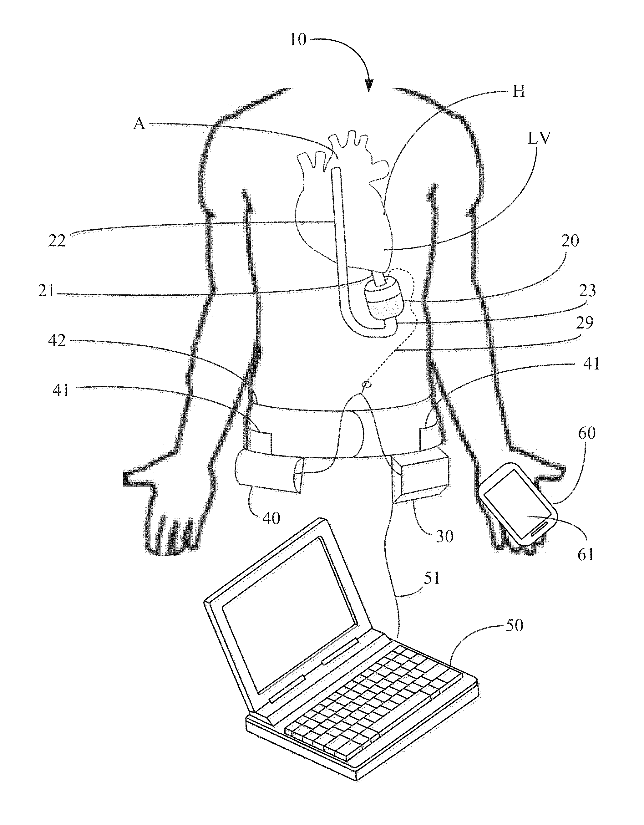
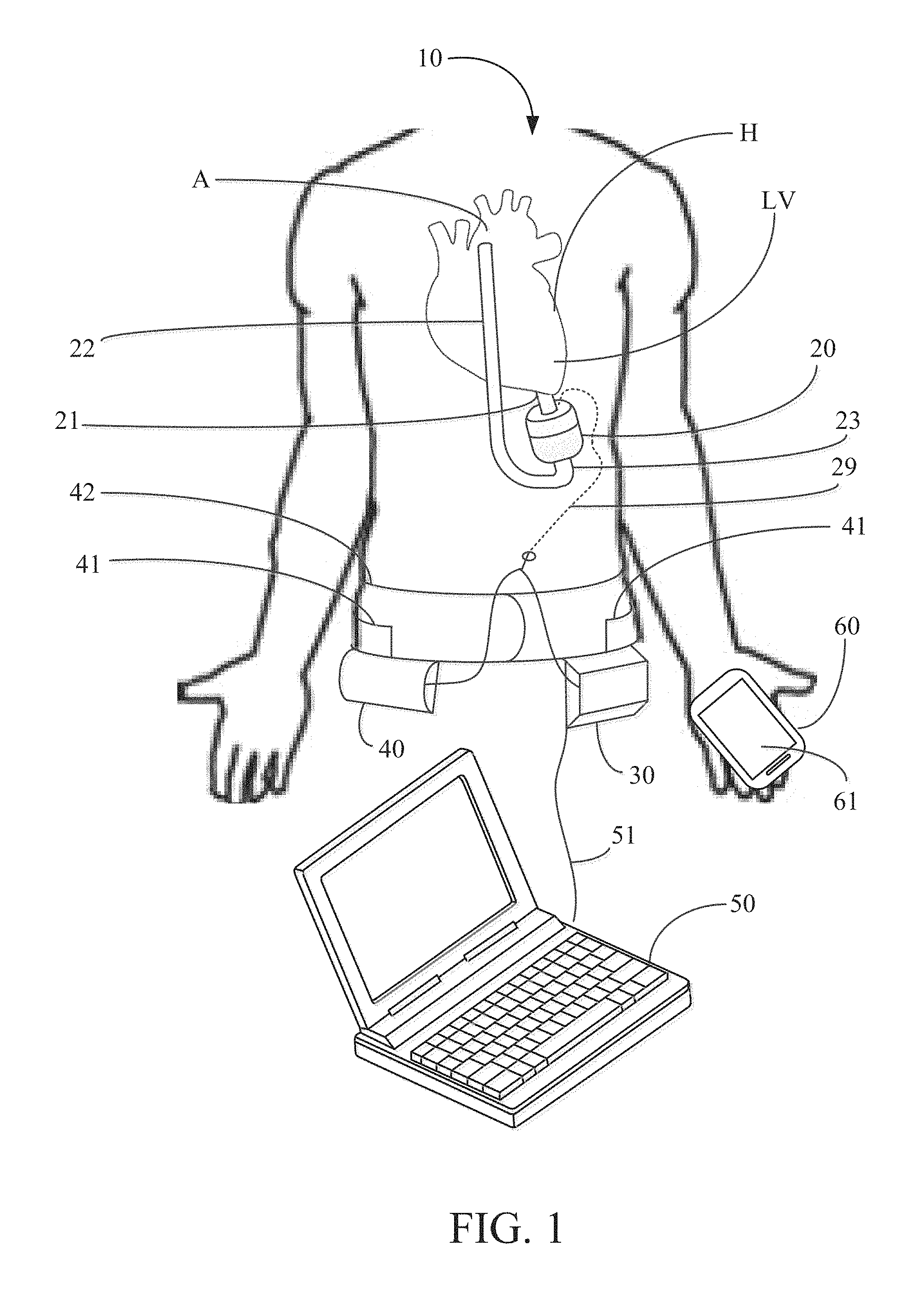
FIG. 1 depicts an exemplary embodiment of the pump system of the present invention comprising an implantable pump, controller, battery, programmer and mobile device.
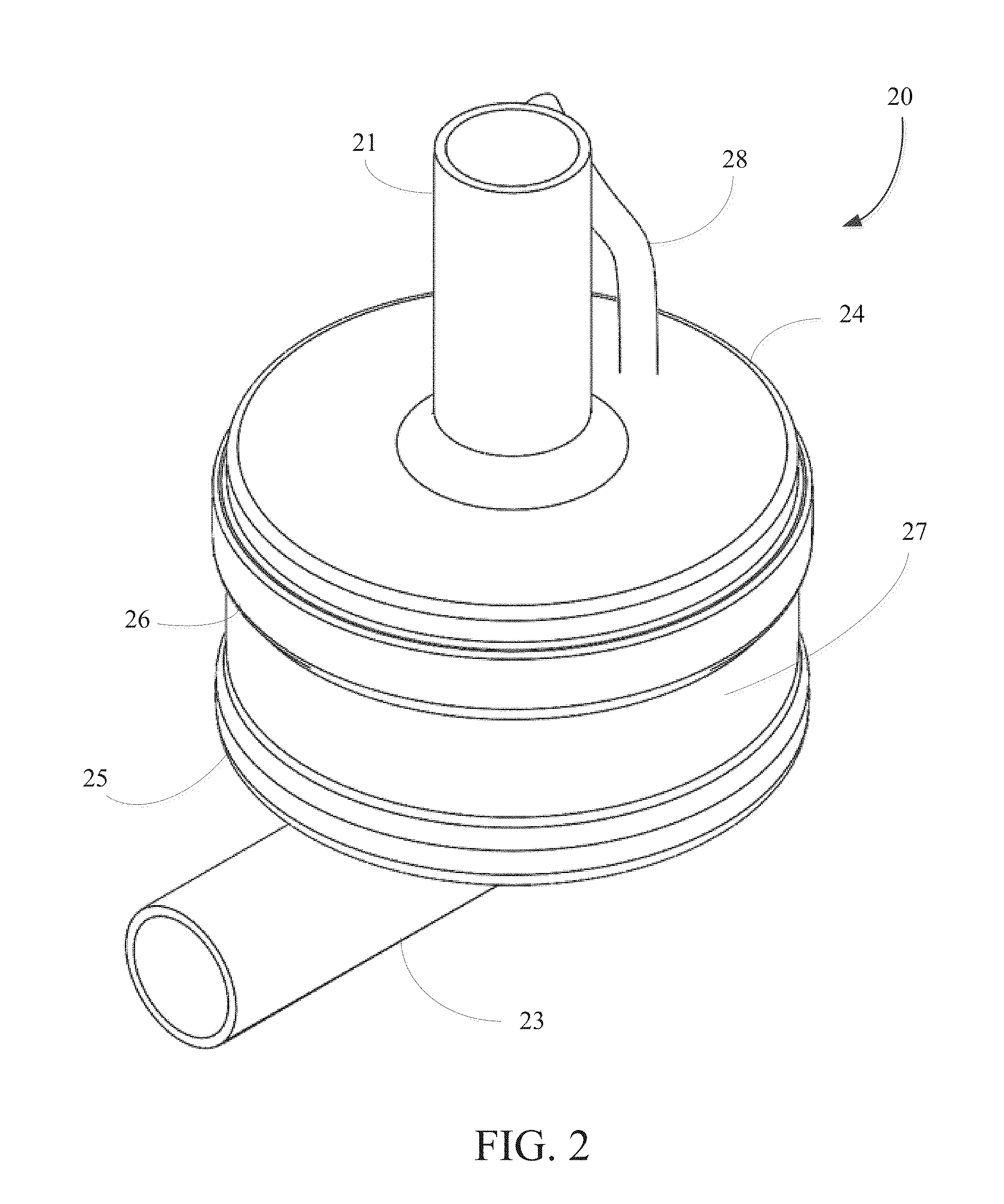
FIG. 2 is a perspective view of the implantable pump of FIG. 1.
FIGS. 3A and 3B are, respectively, a perspective view and a schematic view of the electronic components of an exemplary embodiment of the controller of the present invention.
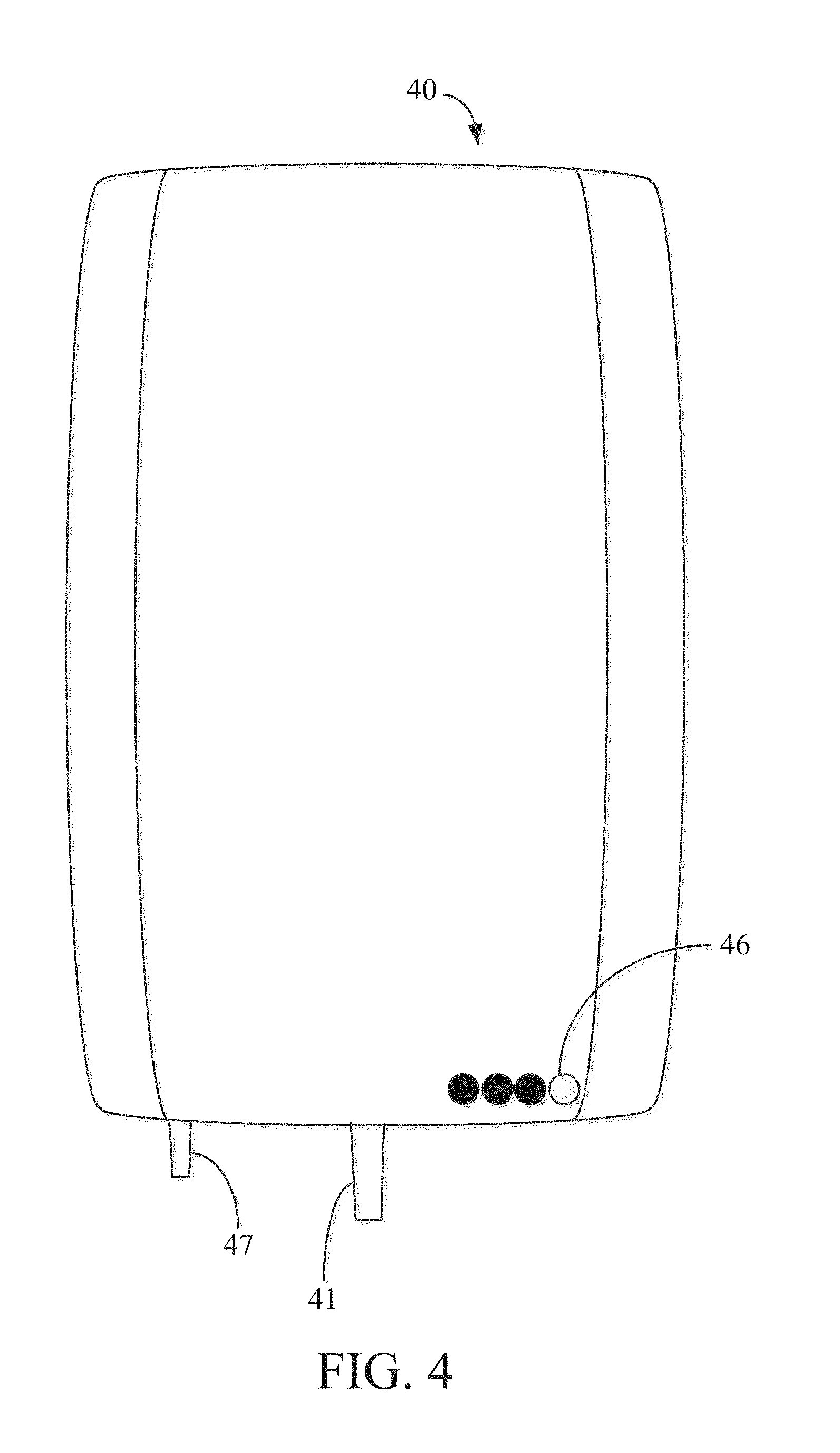
FIG. 4 is a plan view of an extracorporeal battery for use in the pump system of the present invention.
FIGS. 5A and 5B are, respectively, a perspective view and a schematic view of the electronic components of an exemplary embodiment of the programmer of the present invention.
FIG. 6 is a perspective view of the pump assembly of the present invention.
FIG. 7 is a perspective, cut-away view of the implantable pump of the present invention.
FIG. 8 is an exploded view of the implantable pump of the present invention.
FIG. 9 is a perspective cross sectional view of the pump assembly of the present invention.
FIG. 10 is a perspective cross sectional view of the membrane assembly of the present invention.
FIG. 11 is a perspective cross section view of the moving components of the pump assembly according to a first embodiment of the present invention.
FIG. 12 is a cross sectional view of the implantable pump of the present invention.
FIG. 13 is a cross sectional view of a lower portion of the implantable pump depicting the flow channel and membrane assembly in a resting position.
FIG. 14 is a cross sectional view of a lower portion of the implantable pump depicting the flow channel and membrane assembly with the membrane undulating.
DETAILED DESCRIPTION
The implantable pump system of the present invention is particularly well-suited for use as a left ventricular assist device (LVAD), and includes an undulating membrane pump suitable for long-term implantation in a patient having end term heart failure. An implantable pump system constructed in accordance with the principles of the present invention includes an implantable pump and an extracorporeal battery, controller and programmer. The implantable pump includes a housing having an inlet, and outlet, a flexible membrane, and an actuator assembly. When configured as an LVAD, the housing includes an inlet cannula that is inserted into a patient's left ventricle near the apex and an outlet cannula that is surgically placed in fluid communication with the patient's aorta. By activating the actuator assembly within the implantable pump, membrane is induced to undulate, thereby causing blood to be drawn into the pump through the inlet cannula and expelled through the outlet cannula into the aorta. Flow rate and pulsatility may be manipulated by changing one or more of the frequency, amplitude and duty cycle of the actuator assembly.
Referring now to FIG. 1, pump system 10 constructed in accordance with the principles of the present invention is described. Pump system 10 includes implantable pump 20, controller 30, battery 40, programmer 50 and optionally, a software module programmed to run on mobile device 60. Implantable pump 20 is configured to be implanted within a patient's chest so that inlet cannula 21 is coupled to left ventricle LV of heart H. Outlet cannula 22 of pump 20 is configured to be coupled to aorta A. Inlet cannula 21 preferably is coupled to the apex of left ventricle LV, while outlet cannula 22 is coupled to aorta A in the vicinity of the ascending aorta, above the level of the cardiac arteries. Implantable pump 20 may be affixed within the patient's chest using a ring-suture or other conventional technique. Outlet cannula 22, which may comprise a Dacron graft or other synthetic material, is coupled to outlet 23 of implantable pump 20.
Referring now also to FIG. 2, implantable pump 20 in a preferred embodiment consists of upper housing portion 24 joined to lower housing portion 25 along interface 26, for example, by threads or welding, to form fluid tight pump housing 27 that may have a cylindrical shape. Upper housing portion 24 includes inlet cannula 21 and electrical conduit 28 for receiving electrical wires from controller 30 and battery 40. Lower housing portion 25 includes outlet 23 that couples to outlet cannula 22, as shown in FIG. 1. Pump housing 27 is made of a biocompatible material, such as stainless steel, and is sized to be implanted within a patient's chest.
Referring again to FIG. 1, in one embodiment, controller 30 and battery 40 are extracorporeal, and are sized so as to be placed on a belt or garment worn by the patient. Both controller 30 and battery 40 are electrically coupled to implantable pump 20, for example, via cable 29 that extends through a transcutaneous opening in the patient's skin and into electrical conduit 28 of pump housing 27. Illustratively, battery 40 is electrically coupled to controller 30 via cable 41 that is integrated into belt 42. In an alternative embodiment, controller 30 may be enclosed within a biocompatible housing and sized to be implanted subcutaneously in the patient's abdomen. In this alternative embodiment, controller 30 may include a wireless transceiver for bi-directional communications with an extracorporeal programming device and also include a battery that is continuously and inductively charged via extracorporeal battery 40 and an extracorporeal charging circuit. As will be understood, the foregoing alternative embodiment avoids the use of transcutaneous cable 29, and thus eliminates a frequent source of infection for conventional LVAD devices.
Battery 40 preferably comprises a rechargeable battery capable of powering implantable pump 20 and controller 30 for a period of several days, e.g., 3-5 days, before needing to be recharged. Battery 40 may include a separate charging circuit, not shown, as is conventional for rechargeable batteries. Battery 40 preferably is disposed within a housing suitable for carrying on a belt or holster, so as not to interfere with the patient's daily activities.
Programmer 50 may consist of a conventional laptop computer that is programmed to execute programmed software routines, for use by a clinician or medical professional, for configuring and providing operational parameters to controller 30. The configuration and operational parameter data is stored in a memory associated with controller 30 and used by the controller to control operation of implantable pump 20. As described in further detail below, controller 30 directs implantable pump 20 to operate at specific parameters determined by programmer 50. Programmer 50 preferably is coupled to controller 30 via cable 51 only when the operational parameters of the implantable pump are initially set or periodically adjusted, e.g., when the patient visits the clinician.
In accordance with another aspect of the invention, mobile device 60, which may a conventional smartphone, may include an application program for bi-directionally and wirelessly communicating with controller 30, e.g., via WiFi or Bluetooth communications. The application program on mobile device 60 may be programmed to permit the patient to send instructions to controller to modify or adjust a limited number of operational parameters of implantable pump 20 stored in controller 30. Alternatively or in addition, mobile device 60 may be programmed to receive from controller 30 and to display on screen 61 of mobile device 60, data relating to operation of implantable pump 20 or alert or status messages generated by controller 30.
With respect to FIGS. 3A and 3B, controller 30 is described in greater detail. As depicted in FIG. 1, controller 30 may be sized and configured to be worn on the exterior of the patient's body and may be incorporated into a garment such as a belt or a vest. Controller 30 includes input port 31, battery port 32, output port 33, indicator lights 34, display 35, status lights 36 and buttons 37.
Input port 31 is configured to periodically and removably accept cable 51 to establish an electrical connection between programmer 50 and controller 30, e.g., via a USB connection. In this manner, a clinician may couple to controller 30 to set or adjust operational parameters stored in controller 30 for controlling operation of implantable pump. In addition, when programmer 50 is coupled to controller 30, the clinician also may download from controller 30 data relating to operation of the implantable pump, such as actuation statistics, for processing and presentation on display 55 of programmer 50. Alternatively, or in addition, controller 30 may include a wireless transceiver for wirelessly communicating such information with programmer 50. In this alternative embodiment, wireless communications between controller 30 and programmer 50 may be encrypted with an encryption key associated with a unique identification number of the controller, such as a serial number.
Battery port 32 is configured to removably accept cable 41, illustratively shown in FIG. 1 as integrated with belt 42, so that cable 41 routed through the belt and extends around the patient's back until it couples to controller 30. In this manner, battery 40 may be removed from belt 42 and disconnected from controller 30 to enable the patient to periodically replace the battery with a fully charged battery. It is expected that the patient will have available to him or her at least two batteries, so that while one battery is coupled to controller 30 to energize the controller and implantable pump, the other battery may be connected to a recharging station. Alternatively, or in addition, battery port 32 may be configured to accept a cable that is coupled directly to a power supply, such a substantially larger battery/charger combination that permits the patient to remove battery 40 while lying supine in a bed, e.g., to sleep.
Output port 33 is electrically coupled to cable 29, which in turn is coupled to implantable pump 20 through electrical conduit 28 of pump housing 27. Cable 29 provides both energy to energize implantable pump 20 in accordance with the configuration settings and operational parameters stored in controller 30, and to receive data from sensors disposed in implantable pump 20. In one embodiment, cable 29 may comprise an electrical cable having a biocompatible coating and is designed to extend transcutaneously. Cable 29 may be impregnated with pharmaceuticals to reduce the risk of infection, the transmission of potentially hazardous substances or to promote healing where it extends through the patient's skin.
As mentioned above, controller 30 may include indicator lights 34, display 35, status lights 36 and buttons 37. Indicator lights 34 may visually display information relevant to operation of the system, such as the remaining life of battery 40. Display 35 may be a digital liquid crystal display that displays real time pump performance data, physiological data of the patient, such as heart rate, or operational parameters of the implantable pump, such as the target pump pressure or flow rate, etc. When it is determined that certain parameter conditions exceed preprogrammed thresholds, an alarm may be sounded and an alert may be displayed on display 35. Status lights 36 may comprise light emitting diodes (LEDs) that are turned on or off to indicate whether certain functionality of the controller or implantable pump is active. Buttons 37 may be used to wake up display 35, to set or quiet alarms, etc.
With respect to FIG. 3B, the components of the illustrative embodiment of controller 30 of FIG. 3A are described. In addition to the components of controller 30 described in connection with FIG. 3A, controller 30 further includes microprocessor 38, memory 39, battery 43, optional transceiver 44 and amplifier circuitry 45. Microprocessor may be a general purpose microprocessor, for which programming to control operation of implantable pump 20 is stored in memory 39. Memory 39 also may store configuration settings and operational parameters for implantable pump 20. Battery 40 supplies power to controller 30 to provide continuity of operation when battery 40 is periodically swapped out. Optional transceiver 44 to facilitates wireless communication with programmer 50 and/or mobile device 60 via any of a number of well-known communications standards, including BLUETOOTH.TM., ZigBee, and/or any IEEE 802.11 wireless standard such as Wi-Fi or Wi-Fi Direct. Controller 30 further may include amplifier circuitry 45 for amplifying electrical signals transferred between controller 30 and implantable pump 20.
Referring now to FIG. 4, battery 40 is described. Battery 40 provides power to implantable pump 20 and also may provide power to controller 30. Battery 40 may consist of a single battery or a plurality of batteries disposed within a housing, and preferably is sized and configured to be worn on the exterior of the patient's body, such as on belt 42. Battery life indicator 46 may be provided on the exterior of battery 40 to indicate the degree to the remaining charge of the battery. Cable 41 may have one end removably coupled to battery 40 and the other end removably coupled to battery port of controller 30 to supply power to energize implantable pump 20. In one embodiment, battery 40 may be rechargeable using a separate charging station, as is known in the art of rechargeable batteries. Alternatively, or in addition, battery 40 may include port 47 which may be removably coupled to a transformer and cable to permit the battery to be recharged using a conventional residential power outlet, e.g., 120 V, 60 Hz AC power.
Referring now to FIGS. 5A-5B, programmer 50 is described. Programmer 50 may be conventional laptop loaded with programmed software routines for configuring controller 30 and setting operational parameters that controller 30 uses to control operation of implantable pump 20. As discussed above, programmer 50 typically is located in a clinician's office or hospital, and is coupled to controller 30 via cable 51 or wirelessly to initially set up controller 30, and then periodically thereafter as required to adjust the operational parameters as may be needed. The operation parameters of controller 30 set using the programmed routines of programmer 50 may include but are not limited to applied voltage, pump frequency, pump amplitude, target flow rate, pulsatility, etc. When first implanted, the surgeon or clinician may use programmer 50 to communicate initial operating parameters to controller 30. Following implantation, the patient periodically may return to the clinician's office for adjustments to the operational parameters which may again be made using programmer 50.
Programmer 50 may be any type of conventional personal computer device such as a laptop or a tablet computer having touch screen capability. As illustrated in FIG. 5B, programmer 50 preferably includes processor 52, memory 53, input/output device 54, display 55, battery 56 and communication unit 57. Memory 53 may include the operating system for the programmer, as well as the programmed routines needed to communicate with controller 30. Communication unit 57 may include any of a number of well-known communication protocols, such as BLUETOOTH.TM., ZigBee, and/or any IEEE 802.11 wireless standard such as Wi-Fi or Wi-Fi Direct. As illustrated in FIG. 5A, the programmed routines used to program and communicate with controller 30 also may provide data for display on the screen of programmer 50 identifying operational parameters with which controller 30 controls implantable pump 20. The programmed routines also may enable programmer 50 to download from controller 30 operational data or physiologic data communicated by the implantable pump and to display that information in real time while the programmer is coupled to the controller via a wired or wireless connection. The transferred data may then be processed and displayed on the screen of programmer 50.
Referring now to FIGS. 6 and 7, a preferred embodiment of pump assembly 70 and implantable pump 20 are illustrated. However, it is understood that pump assemblies and implantable pumps, and components included therein, may have different shapes and sizes than those illustrated in FIGS. 6 and 7 without departing from the invention described herein. As is illustrated in FIG. 7, pump assembly 70 is configured to fit within pump housing 27. To fix pump assembly 70 within pump housing 27, pump assembly 70 may include fixation ring 71, which may extend from and around stator assembly 72, and may be captured between upper housing portion 24 and lower housing portion 25 when the housing portions are assembled, as illustrated in FIG. 7. In this manner, stator assembly 72 may be suspended within the pump housing in close-fitting relation to the interior walls of the pump housing. Fixation ring 71 preferably is a rigid annular structure that is disposed concentrically around stator assembly 72, having a larger diameter than stator assembly 72. Fixation ring 71 may be rigidly coupled to stator assembly 72 via struts 73. Struts 73 may create gap 74 between fixation ring 71 and stator assembly 72, which preferably is about 0.05 mm at its most restricted point.
As shown in FIG. 7, pump assembly 70 may be disposed in pump housing 27 such that fixation ring 71 is captured on step 75 formed between upper housing portion 24 and lower housing portion 25. In this manner, stator assembly 72 may be suspended within, and prevented from moving within, pump housing 27. Pump housing 27 preferably is sized and configured to conform to pump assembly 70 such that, stator assembly 72 does not contact the interior of the pump housing at any location other than at fixation ring 71.
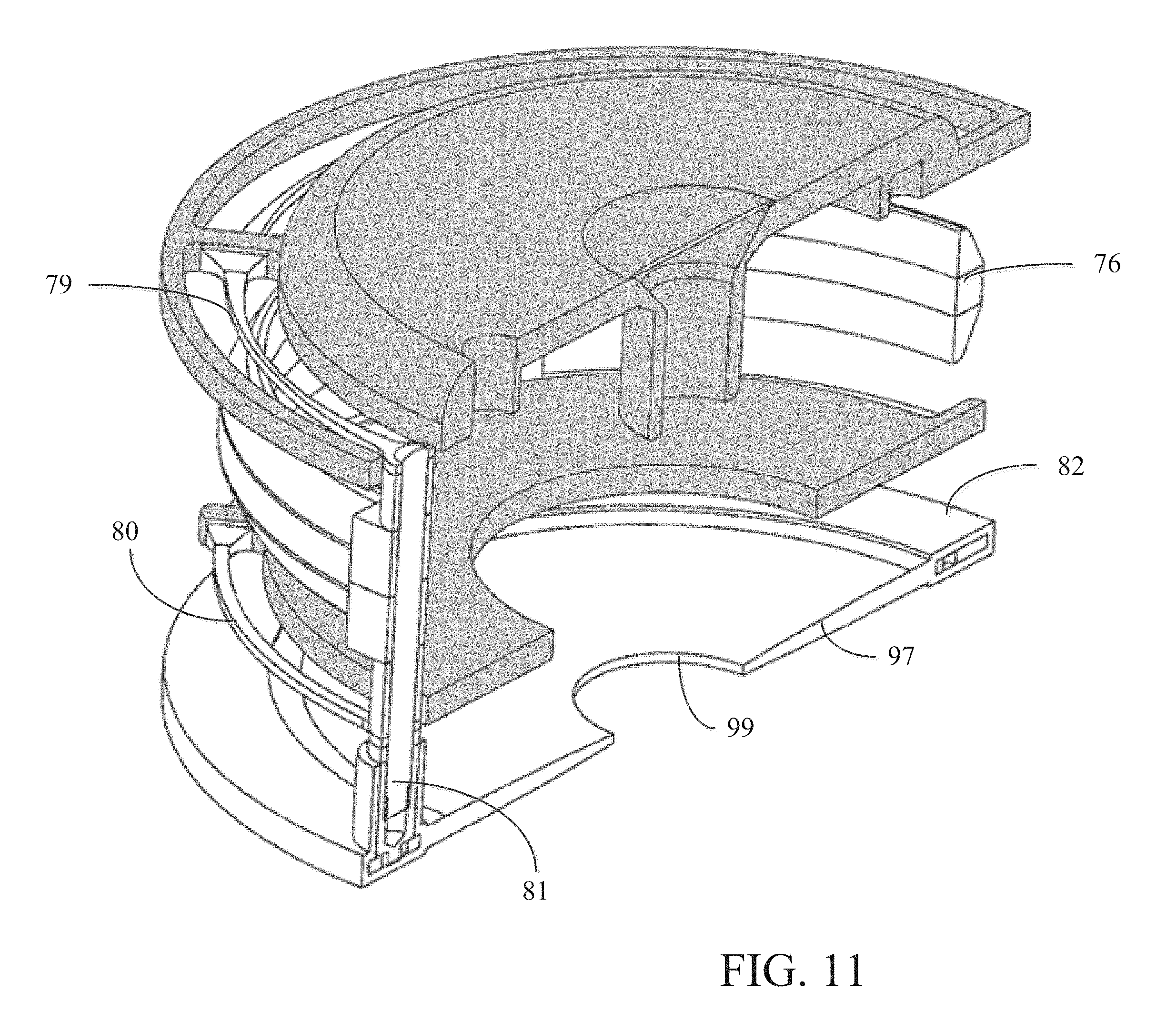
FIG. 8 is an exploded view of implantable pump 20, depicting the arrangement of the internal components of pump assembly 70 arranged between upper housing portion 24 and lower housing portion 25. In particular, pump assembly 70 may comprise stator assembly 72, magnetic ring assembly 76, first electromagnetic coil 77, second electromagnetic coil 78, fixation ring 71, first suspension ring 79, second suspension ring 80, posts 81 and membrane assembly 82. Stator assembly 72 may comprise tapered section 83, electromagnetic coil holder portions 84, 85 and 86, and flanged portion 87. Magnetic ring assembly 76 may comprise magnetic ring 88 and magnetic ring holder portions 89 and 90. First and second electromagnetic coils 77 and 78, together with electromagnetic coil holder portions 84, 85 and 86 may form electromagnet assembly 91. Electromagnet assembly 91 together with stator assembly 72 form an actuator assembly. The actuator assembly together with magnetic ring assembly 76 in turn forms the actuator system of implantable pump 20.
First electromagnetic coil 77 and second electromagnetic coil 78 may be concentrically sandwiched between electromagnetic coil holder portions 84, 85 and 86 to form electromagnet assembly 91. Tapered section 83, which may be coupled to fixation ring 71 and first suspension spring 79, may be located concentrically atop electromagnet assembly 91. Magnetic ring 88 may be disposed with magnetic ring holder portions 89 and 90 to form magnetic ring assembly 76, which may be concentrically disposed for reciprocation over electromagnet assembly 91. Second suspension ring 80 may be disposed concentrically beneath electromagnet assembly 91. Flanged portion 87 may be concentrically disposed below second suspension ring 80. Posts 81 may engage first suspension ring 79, magnetic ring assembly 76 and second suspension ring 80 at equally spaced locations around the actuator assembly. Membrane assembly 82 may be positioned concentrically below flanged portion 87 and engaged with posts 81.
Further details of pump assembly 70 are provided with respect to FIG. 9. Specifically, actuator assembly 95 comprises stator assembly 72 and electromagnet assembly 91, including first and second electromagnetic coils 77 and 78. During use of implantable pump 20, actuator assembly 95 remains stationary relative to pump housing 27. First electromagnetic coil 77 and second electromagnetic coil 78 may be separated by electromagnetic holder portion 85. Controller 30 and battery 40 are electrically coupled to electromagnetic coils 77 and 78 via cable 29 that extends through electrical conduit 28 of pump housing 27 to supply current to electromagnetic coils 77 and 78. First electromagnetic coil 77 and second electromagnetic coil 78 may be in electrical communication with one another or may be configured to operate independently and have separate wired connections to controller 30 and battery 40 via cable 29.
Electromagnetic coils 77 and 78 may be made of any electrically conductive metallic material such as copper and further may comprise of one or more smaller metallic wires wound into a coil. The wires of the electromagnetic coils are insulated to prevent shorting to adjacent conductive material. Other components of pump assembly 70, such as stator assembly 72, preferably also are insulated and/or made of non-conductive material to reduce unwanted transmission of the electrical signal.
Actuator assembly 95 may be surrounded by first suspension ring 79 and second suspension ring 80. Suspension rings 79 and 80 may be annular in shape and fit concentrically around actuator assembly 95. First suspension ring 79 preferably is rigidly affixed to tapered section 83 near a top portion of stator assembly 72 via struts 73 extending from the suspension ring to the stator assembly. As discussed above, struts 73 may also affix fixation ring 71 to stator assembly 72. Fixation ring 71 and first suspension spring 79 may be sized and positioned such that a gap of no less than 0.5 mm exists between first suspension ring 79 and fixation ring 71. Second suspension ring 80 similarly may be rigidly affixed via struts near the bottom of stator assembly 72, below electromagnet assembly 91. Suspension rings 79 and 80 preferably are sized and shaped such that when suspension rings 79 and 80 are positioned surrounding actuator assembly 95, a gap of no less than 0.5 mm exists between actuator assembly 95 and suspension rings 79 and 80.
First suspension ring 79 and second suspension ring 80 may comprise stainless steel having elastic properties and which exhibits a spring force when deflected in a direction normal to the plane of the spring. First suspension ring 79 and second suspension ring 80 may be substantially rigid with respect to forces applied tangential to the suspension ring. In this manner, first suspension ring 79 and second suspension ring 80 may exhibit a spring tension when deformed up and down relative to a vertical axis of the actuator assembly but may rigidly resist movement along any other axis, e.g., tilt or twist movements.
Magnetic ring assembly 76 may be annular in shape and concentrically surrounds actuator assembly 95. Magnetic ring 88 may comprise one or more materials exhibiting magnetic properties such as iron, nickel, cobalt or various alloys. Magnetic ring 88 may be made of a single unitary component or comprise several magnetic components that are coupled together. Magnetic ring assembly 76 may be sized and shaped such that when it is positioned concentrically over actuator assembly 95, a gap of no less than 0.5 mm exists between an outer lateral surface of actuator assembly 95 and an interior surface of magnetic ring assembly 76.
Magnetic ring assembly 76 may be concentrically positioned around actuator assembly 95 between first suspension ring 79 and second suspension ring 80, and may be rigidly coupled to first suspension ring 79 and second suspension ring 80. Magnetic ring assembly 76 may be rigidly coupled to the suspension rings by more than one post 81 spaced evenly around actuator assembly 95 and configured to extend parallel to a central axis of pump assembly 70. Suspension rings 79 and 80 and magnetic ring assembly 76 may be engaged such that magnetic ring assembly 76 is suspended equidistant between first electromagnetic coil 77 and second electromagnetic coil 78 when the suspension rings are in their non-deflected shapes. Each of suspension rings 79 and 80 and magnetic ring holder portions 89 and 90 may include post receiving regions for engaging with posts 81 or may be affixed to posts 81 in any suitable manner that causes suspension rings 79 and 80 and magnetic ring assembly 76 to be rigidly affixed to posts 81. Posts 81 may extend beyond suspension rings 79 and 80 to engage other components, such as flanged portion 87 and membrane assembly 82.
First electromagnetic coil 77 may be activated by controller applying an electrical signal from battery 40 to first electromagnetic coil 77, thus inducing current in the electromagnetic coil and generating a magnetic field surrounding electromagnetic coil 77. The direction of the current in electromagnetic coil 77 and the polarity of magnetic ring assembly 76 nearest electromagnetic coil 77 may be configured such that the first electromagnetic coil magnetically attracts or repeals magnetic ring assembly 76 as desired. Similarly, a magnetic field may be created in second electromagnetic coil 78 by introducing a current in the second electromagnetic coil. The direction of the current in second electromagnetic coil 78 and the polarity of magnetic ring assembly 76 nearest the second electromagnetic coil also may be similarly configured so that first electromagnetic coil 77 magnetically attracts or repels magnetic ring assembly 76 when an appropriate current is induced in second electromagnetic coil 78.
Because magnetic ring assembly 76 may be rigidly affixed to posts 81, which in turn may be rigidly affixed to first suspension ring 79 and second suspension ring 80, the elastic properties of the suspension rings permit magnetic ring assembly 76 to move up towards first electromagnetic coil 77 or downward toward second electromagnetic coil 78, depending upon the polarity of magnetic fields generated by the electromagnetic rings. In this manner, when magnetic ring assembly 76 experiences an upward magnetic force, magnetic ring assembly 76 deflects upward towards first electromagnetic coil 77. As posts 81 move upward with magnetic ring assembly 76, posts 81 cause the suspensions rings 79 and 80 to elastically deform, which creates a spring force opposite to the direction of movement. When the magnetic field generated by the first electromagnetic coil collapses, when the electrical current ceases, this downward spring force causes the magnetic ring assembly to return to its neutral position. Similarly, when magnetic ring assembly 76 is magnetically attracted downward, magnetic ring assembly 76 deflects downward towards second electromagnetic ring 78. As posts 81 move downward with magnetic ring assembly 76, posts 81 impose an elastic deformation of the first and second suspension rings, thus generating a spring force in the opposite direction. When the magnetic field generated by the second electromagnetic ring collapses, when the electrical current ceases, this upward spring force causes the magnetic ring assembly to again return to its neutral position.
Electromagnetic coils 77 and 78 may be energized separately, or alternatively, may be connected in series to cause the electromagnetic coils to be activated simultaneously. In this configuration, first magnetic coil may be configured to experience a current flow direction opposite that of the second electromagnetic coil. Accordingly, when current is induced to first electromagnetic coil 77 to attract magnetic ring assembly 76, the same current is applied to second electromagnetic coil 78 to induce a current that causes second electromagnetic coil 78 to repel magnetic ring assembly 76. Similarly, when current is induced to second electromagnetic coil 78 to attract magnetic ring assembly 76, the current applied to first electromagnetic coil 77 causes the first electromagnetic coil to repel magnetic ring assembly 76. In this manner, electromagnetic coils 77 and 78 work together to cause deflection of magnetic ring assembly 76.
By manipulating the timing and intensity of the electrical signals applied to the electromagnetic coils, the frequency at which magnetic ring assembly 76 deflects towards the first and second electromagnetic coils may be altered. For example, by alternating the current induced in the electromagnetic coils more frequently, the magnetic ring assembly may be caused to cycle up and down more times in a given period. By increasing the amount of current, the magnetic ring assembly may be deflected at a faster rate and caused to travel longer distances.
Alternatively, first electromagnetic coil 77 and second electromagnetic coil 78 may be energized independently. For example, first electromagnetic coil 77 and second electromagnetic coil 78 may be energized at varying intensities; one may be coordinated to decrease intensity as the other increases intensity. In this manner, intensity of the signal applied to second electromagnetic coil 78 to cause downward magnetic attraction may simultaneously be increased as the intensity of the signal applied to first electromagnetic coil 77 causes an upward magnetic attraction that decreases.
In accordance with one aspect of the invention, movements of magnetic ring assembly 76 may be translated to membrane assembly 82 which may be disposed concentrically below stator assembly 72. Membrane assembly 82 preferably is rigidly attached to magnetic ring assembly 76 by posts 81. In the embodiment depicted in FIG. 9, posts 81 may extend beyond second suspension ring 80 and coupled to membrane assembly 82.
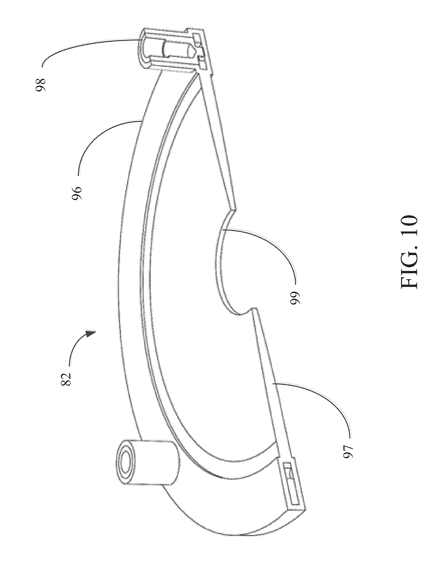
Referring now to FIG. 10, one embodiment of membrane assembly 82 is described in greater detail. Membrane assembly 82 may comprise rigid membrane ring 96 and membrane 97. Rigid membrane ring 96 exhibits rigid properties under typical forces experienced during the full range of operation of the present invention. Post reception sites 98 may be formed into rigid membrane ring 96 to engage membrane assembly 82 with posts 81. Alternatively, posts 81 may be attached to rigid membrane ring 96 in any other way which directly translates the motion of magnetic ring assembly 76 to rigid membrane ring 96. Rigid membrane ring 96 may be affixed to membrane 97 and hold the membrane in tension. Membrane 97 may be molded directly onto rigid membrane ring 96 or may be affixed to rigid membrane ring 96 in any way that holds membrane 97 uniformly in tension along its circumference. Membrane 97 alternatively may include a flexible pleated structure where it attaches to rigid membrane ring 96 to increase the ability of the membrane to move where the membrane is affixed to rigid membrane ring 96. Membrane 97 may further include circular aperture 99 disposed in the center of the membrane.
In a preferred embodiment, membrane 97 has a thin, planar shape and is made of an elastomer having elastic properties and good durability. Alternatively, membrane 97 may have a uniform thickness from the membrane ring to the circular aperture. As a yet further alternative, membrane 97 may vary in thickness and exhibit more complex geometries. For example, as shown in FIG. 10, membrane 97 may have a reduced thickness as the membrane extends from rigid membrane ring 96 to circular aperture 99. Alternatively, or in addition to, membrane 97 may incorporate metallic elements such as a spiral spring to enhance the spring force of the membrane in a direction normal to plane of the membrane, and this spring force may vary radially along the membrane. In yet another embodiment, membrane 97 may be pre-formed with an undulating shape.
FIG. 11 depicts moving portions of the embodiment of pump assembly 70 shown in FIGS. 6-9 as non-grayed out elements. Non-moving portions of the pump assembly, including actuator assembly 95 and electromagnet assembly 91 (partially shown) may be fixed to pump housing 27 by fixation ring 71. Moving portions of pump assembly 70 may include posts 81, first suspension spring 79, magnetic ring assembly 76, second suspension spring 80 and membrane assembly 82. As magnetic ring assembly 76 moves up and down, the movement is rigidly translated by posts 81 to membrane assembly 82. Given the rigidity of the posts, when magnetic ring assembly 76 travels a certain distance upward or downward, membrane assembly 82 may travel the same distance. For example, when magnetic ring assembly 76 travels 4 mm from a position near first electromagnetic coil 77 to a position near second electromagnetic coil 78, membrane assembly 82 may also travel 4 mm in the same direction. Similarly, the frequency at which magnetic ring assembly 76 traverses the space between the first and second electromagnetic coils may be the same frequency at which membrane assembly 82 travels the same distance.
Referring now to FIG. 12, in the embodiment of implantable pump 20 described in FIGS. 6-9, blood may enter implantable pump 20 from the left ventricle through inlet cannula 21 and flow downward along pump assembly 70 into delivery channel 100, defined by the interior surface of pump housing 27 and exterior of pump assembly 70. Delivery channel 100 begins at the top of stator assembly 72 and extends between tapered section 83 and the interior of pump housing 27. As the blood moves down tapered section 83, it is directed through gap 74 and into a vertical portion of delivery channel 100 in the area between pump housing 27 and actuator assembly 95, and including in the gap between magnetic ring assembly 76 and electromagnet assembly 91. Delivery channel 100 extends down to flanged portion 87 of stator assembly 72, which routes blood into flow channel 101, within which membrane assembly 82 is suspended. By directing blood from inlet cannula 21 through delivery channel 100 to flow channel 101, delivery channel 100 delivers blood to membrane assembly 82. By actuating electromagnetic coils 77 and 78, membrane 97 may be undulated within flow channel 101 to induce wavelike formations in membrane 97 that move from the edge of the membrane towards circular aperture 99. Accordingly, when blood is delivered to membrane assembly 82 from delivery channel 100, it may be propelled radially along both the top and bottom of membrane 97 towards circular aperture 99, and from there out of outlet 23.
In accordance with one aspect of the present invention, the undulating membrane pump described herein avoids thrombus formation by placing all moving parts directly within the primary flow path, thereby reducing the risk of flow stagnation. Specifically, the moving components depicted in FIG. 11, including magnetic ring assembly 76, suspension rings 79 and 80, posts 81 and membrane assembly 82 all are located within delivery channel 100 and flow channel 101. Flow stagnation may further be avoided by eliminating secondary flow paths that may experience significantly slower flow rates.
Turning now to FIGS. 13 and 14, a lower portion of implantable pump 20, including flanged portion 87, membrane assembly 82 and lower housing portion 23 is shown. Delivery channel 100 may be in fluid communication with membrane assembly 82 and flow channel 101 which is defined by a bottom surface of flanged portion 87 and the interior surface of lower housing portion 25. Flanged portion 87 may comprise feature 102 that extends downward as the bottom of flanged portion 87 moves radially inward. The interior surface of lower housing portion 25 may also slope upward as it extends radially inward. The combination of the upward slope of the interior surface of lower housing portion 25 and the bottom surface of flanged portion 87 moving downward narrows flow channel 101 as the channel moves radially inwards from delivery channel 100 to circular aperture 99 of membrane 97, which is disposed about pump outlet 23.
As explained above, membrane assembly 82 may be suspended by posts 81 within flow channel 101 below the bottom surface of flanged portion 87 and above the interior surface of lower housing portion 25. Membrane assembly 82 may be free to move up and down in the vertical direction within flow channel 101, which movement is constrained only by suspension rings 79 and 80. Membrane assembly 82 may be constrained from twisting, tilting or moving in any direction in flow channel 101 other than up and down by rigid posts 81 and by the suspension rings.
Flow channel 101 is divided by membrane 97 into an upper flow channel and a lower flow channel by membrane 97. The geometry of membrane 97 may be angled such that when membrane assembly 82 is at rest, the top surface of membrane 97 is parallel to the bottom surface of flanged portion 87 and the bottom surface of membrane 97 is parallel to the opposing surface of lower housing portion 25. Alternatively, membrane 97 may be sized and shaped such that when membrane assembly 82 is at rest, the upper and lower flow channels narrow as they move radially inward from delivery channel 100 to circular aperture 99 in membrane 97.
Referring now also to FIG. 14, as rigid membrane ring 96 is caused by posts 81 to move up and down in flow channel 101, the outermost portion of membrane 97 nearest rigid membrane ring 96, moves up and down with rigid membrane ring 96. Membrane 97, being flexible and having elastic properties, gradually translates the up and down movement of the membrane portion nearest rigid membrane ring 96 along membrane 97 towards circular aperture 99. This movement across flexible membrane 97 causes wavelike deformations in the membrane which may propagate inwards from rigid membrane ring 96 towards aperture 99.
The waves formed in the undulating membrane may be manipulated by changing the speed at which rigid membrane ring 96 moves up and down as well as the distance rigid membrane ring 96 moves up and down. As explained above, the amplitude and frequency at which rigid membrane ring 96 moves up and down is determined by the amplitude and frequency at which magnetic ring assembly 76 reciprocates over electromagnet assembly 91 Accordingly, the waves formed in the undulating membrane may be adjusted by changing the frequency and amplitude at which magnetic ring assembly 76 is reciprocated.
When blood is introduced into flow channel 101 from delivery channel 100, the undulations in membrane 97 cause blood to be propelled toward circular aperture 99 and out of pump housing 27 via outlet 23. The transfer of energy from the membrane to the blood is directed radially inward along the length of the membrane towards aperture 99, and propels the blood along the flow channel towards outlet 23 along both sides of membrane 97.
FIG. 15 shows that when rigid membrane ring 96 moves downward in unison with magnetic ring assembly 76, the upper portion of flow channel 101 near delivery channel 100 expands, causing blood from delivery channel 100 to fill the upper portion of the flow channel near the outer region of membrane 97. As rigid membrane ring 96 moves upward, the upper portion of flow channel 101 begins to narrow near rigid membrane ring 96, causing wave-like deformations to translate across the membrane. As the wave propagates across membrane 97, blood in the upper portion of flow channel 101 is propelled towards circular aperture and ultimately out of pump housing 27 through outlet 23. Simultaneously, as rigid membrane ring 96 moves upwards, the lower portion of flow channel 101 nearest the outer portion of membrane 97 begins to enlarge, allowing blood from delivery channel 100 to flow into this region. Subsequently, when rigid membrane ring 96 is again thrust downwards, the region of lower portion of flow channel 101 nearest outer portion of membrane 97 begins to narrow, causing wave-like deformations to translate across the membrane that propel blood towards outlet 23.
By manipulating the waves formed in the undulating membrane by changing the frequency and amplitude at which magnetic ring assembly 76 moves up and down, the pressure gradient within flow channel 101 and ultimately the flow rate of the blood moving through flow channel 101 may be adjusted. Appropriately controlling the movement of magnetic ring assembly 76 permits oxygen-rich blood to be effectively and safely pumped from the left ventricle to the aorta and throughout the body as needed.
In addition to merely pumping blood from the left ventricle to the aorta, implantable pump 20 of the present invention may be operated to closely mimic physiologic pulsatility, without loss of pump efficiency. In the embodiment detailed above, pulsatility may be achieved nearly instantaneously by changing the frequency and amplitude at which magnetic ring assembly 76 moves, to create a desired flow output, or by ceasing movement of the magnetic ring assembly for a period time to create a period of low or no flow output. Unlike typical rotary pumps, which require a certain period of time to attain a set number of rotations per minute to achieve a desired fluid displacement and pulsatility, implantable pump 20 may achieve a desired flow output nearly instantaneously and similarly may cease output nearly instantaneously due to the very low inertia generated by the small moving mass of the moving components of the pump assembly. The ability to start and stop on-demand permits rapid changes in pressure and flow. Along with the frequency and amplitude, the duty cycle, defined by the percentage of time membrane 97 is excited over a set period of time, may be adjusted to achieve a desired flow output and pulsatility, without loss of pump efficiency. Even holding frequency and amplitude constant, flow rate may be altered by manipulating the duty cycle between 0 and 100%.
In accordance with another aspect of the invention, controller 30 may be programmed by programmer 50 to operate at selected frequencies, amplitudes and duty cycles to achieve a wide range of physiologic flow rates and with physiologic pulsatilities. For example, programmer 50 may direct controller 30 to operate implantable pump 20 at a given frequency, amplitude and/or duty cycle during a period of time when a patient is typically sleeping and may direct controller 30 to operate implantable pump 20 at a different frequency, amplitude and or duty cycle during time periods when the patient is typically awake. Controller 30 or implantable pump also may include an accelerometer or position indicator to determine whether the patient is supine or ambulatory, the output of which may be used to move from one set of pump operating parameters to another. When the patient experiences certain discomfort or a physician determines that the parameters are not optimized, physician may alter one or more of at least frequency, amplitude and duty cycle to achieve the desired functionality. Alternatively, controller 30 or mobile device 60 may be configured to alter one or more of frequency, amplitude and duty cycle to suit the patient's needs.
Implantable pump 20 further may comprise one or more additional sensors for adjusting flow output and pulsatility according to the demand of the patient. Sensors may be incorporated into implantable pump 20 or alternatively or in addition to may be implanted elsewhere in or on the patient. The sensors preferably are in electrical communication with controller 30, and may monitor operational parameters that measure the performance of implantable pump 20 or physiological sensors that measure physiological parameters of the patients such as heart rate or blood pressure. By using one or more physiological sensors, pulsatile flow may be synchronized with a cardiac cycle of the patient by monitoring blood pressure or muscle contractions, for example, and synchronizing the duty cycle according to the sensed output.
Controller 30 may compare physiological sensor measurements to current implantable pump output. If it is determined by analyzing sensor measurements that demand exceeds current output, frequency, amplitude and/or duty cycle may be automatically adjusted to meet current demand. Similarly, the controller may determine that current output exceeds demand and thus alter output by changing frequency, amplitude and/or duty cycle. Alternatively, or in addition to, when it is determined that demand exceeds current output, an alarm may sound from controller 30. Similarly, operational measurements from operational sensors may be compared against predetermined thresholds and where measurements exceed predetermined thresholds or a malfunction is detected, an alarm may sound from controller 30.
Implantable pump 20 is sized and shaped to produce physiological flow rates, pressure gradients and pulsatility at an operating point at which maximum efficiency is achieved. Specially, implantable pump 20 may be sized and shaped to produce physiological flow rates ranging from 4 to 6 liters per minute at pressure gradients lower than a threshold value associated with hemolysis. Also, to mimic a typical physiological pulse of 60 beats per minute, implantable pump 20 may pulse about once per second. To achieve such pulsatility, a duty cycle of 50% may be utilized with an "on" period of 0.5 seconds and an "off" period of 0.5 seconds. For a given system, maximum efficiency at a specific operating frequency, amplitude and voltage may be achieved while producing a flow rate of 4 to 6 liters per minute at a duty cycle of 50% by manipulating one or more of the shape and size of blood flow channels, elastic properties of the suspension rings, mass of the moving parts, membrane geometries, and elastic properties and friction properties of the membrane. In this manner, implantable pump 20 may be designed to produce desirable physiological outputs while continuing to function at optimum operating parameters.
By adjusting the duty cycle, implantable pump 20 may be configured to generate a wide range of output flows at physiological pressure gradients. For example, for an exemplary LVAD system configured to produce 4 to 6 liters per minute at a duty cycle of 50%, optimal operating frequency may be 120 Hz. For this system, flow output may be increased to 10 liters per minute or decreased to 4 liters per minute, for example, by changing only the duty cycle. As duty cycle and frequency operate independent of one another, duty cycle may be manipulated between 0 and 100% while leaving the frequency of 120 Hz unaffected.
The implantable pump system described herein, tuned to achieve physiological flow rates, pressure gradients and pulsatility, also avoids hemolysis and platelet activation by applying low to moderate shear forces on the blood, similar to those exerted by a healthy heart. The moving components are rigidly affixed to one another and do not incorporate any parts that would induce friction, such as mechanical bearings or gears. In the embodiment detailed above, delivery channel 100 may be sized and configured to also avoid friction between moving magnetic ring assembly 76, suspension rings 79 and 80, posts 81 and lower housing portion 25 by sizing the channel such that clearances of at least 0.5 mm are maintained between all moving components. Similarly, magnetic ring assembly 76, suspension rings 79 and 80, and posts 81 all may be offset from stator assembly 72 by at least 0.5 mm to avoid friction between the stator assembly and the moving parts.
While various illustrative embodiments of the invention are described above, it will be apparent to one skilled in the art that various changes and modifications may be made therein without departing from the invention. For example, pump assembly 70 shown in FIG. 9 may be ordered differently and may include additional or fewer components of various sizes and composition. The appended claims are intended to cover all such changes and modifications that fall within the true spirit and scope of the invention.
* * * * *
D00000
D00001
D00002
D00003
D00004
D00005
D00006
D00007
D00008
D00009
D00010
D00011
D00012

D00013
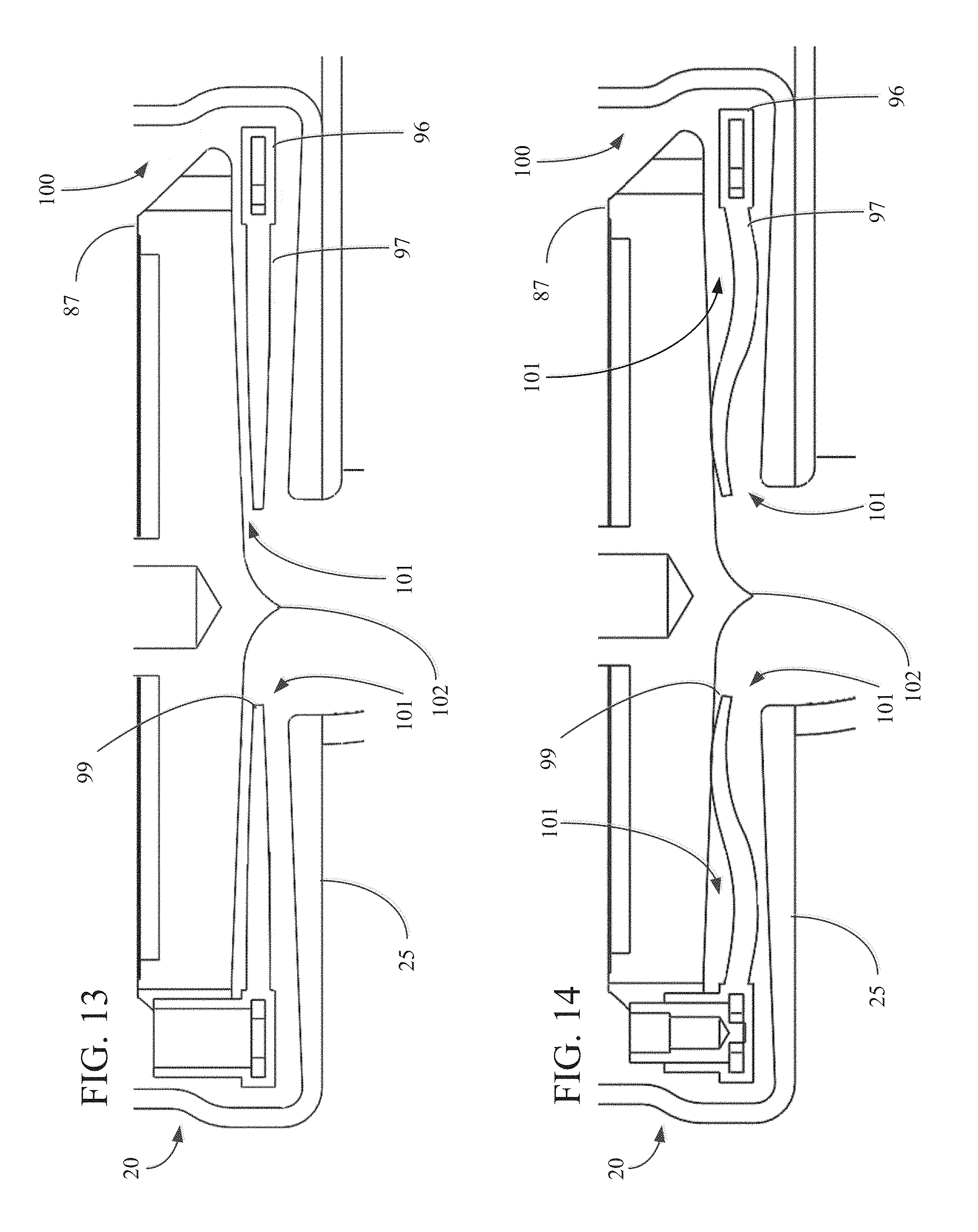
XML
uspto.report is an independent third-party trademark research tool that is not affiliated, endorsed, or sponsored by the United States Patent and Trademark Office (USPTO) or any other governmental organization. The information provided by uspto.report is based on publicly available data at the time of writing and is intended for informational purposes only.
While we strive to provide accurate and up-to-date information, we do not guarantee the accuracy, completeness, reliability, or suitability of the information displayed on this site. The use of this site is at your own risk. Any reliance you place on such information is therefore strictly at your own risk.
All official trademark data, including owner information, should be verified by visiting the official USPTO website at www.uspto.gov. This site is not intended to replace professional legal advice and should not be used as a substitute for consulting with a legal professional who is knowledgeable about trademark law.