Minimally invasive surgical apparatus and methods
Dickinson , et al. Sep
U.S. patent number 10,398,580 [Application Number 14/141,913] was granted by the patent office on 2019-09-03 for minimally invasive surgical apparatus and methods. This patent grant is currently assigned to LimFlow GmbH. The grantee listed for this patent is LimFlow GmbH. Invention is credited to Robert Julian Dickinson, Ajay Kumar Jain, Andrew Robert Pacey, Martin Terry Rothman.


| United States Patent | 10,398,580 |
| Dickinson , et al. | September 3, 2019 |
Minimally invasive surgical apparatus and methods
Abstract
Apparatus and methods are described for performing percutaneous catheter-based interventional surgery. The apparatus comprises first and second devices that are located in adjacent body cavities, such as adjacent blood vessels, the first device being capable of transmitting a directional signal that can be received by the second device. The direction of the signal is correlated with the facility to direct therapy, such that improved accuracy in therapy placement is thereby achieved. Methods for treating patients utilizing the means and apparatus are also provided.
| Inventors: | Dickinson; Robert Julian (London, GB), Pacey; Andrew Robert (Herts, GB), Rothman; Martin Terry (Santa Rosa, CA), Jain; Ajay Kumar (London, GB) | ||||||||||
|---|---|---|---|---|---|---|---|---|---|---|---|
| Applicant: |
|
||||||||||
| Assignee: | LimFlow GmbH (Dresden,
DE) |
||||||||||
| Family ID: | 33186680 | ||||||||||
| Appl. No.: | 14/141,913 | ||||||||||
| Filed: | December 27, 2013 |
Prior Publication Data
| Document Identifier | Publication Date | |
|---|---|---|
| US 20140236274 A1 | Aug 21, 2014 | |
Related U.S. Patent Documents
| Application Number | Filing Date | Patent Number | Issue Date | ||
|---|---|---|---|---|---|
| 11662128 | |||||
| PCT/GB2005/003480 | Sep 8, 2005 | ||||
Foreign Application Priority Data
| Sep 8, 2004 [GB] | 0419954.3 | |||
| Current U.S. Class: | 1/1 |
| Current CPC Class: | A61B 17/3478 (20130101); A61B 17/2202 (20130101); A61B 17/11 (20130101); A61B 34/20 (20160201); A61F 2/966 (20130101); A61B 2017/00252 (20130101); A61B 2034/2051 (20160201); A61B 2017/22082 (20130101); A61B 2017/1139 (20130101); A61B 2017/1107 (20130101); A61B 2090/3929 (20160201); A61B 2090/3786 (20160201); A61B 2034/2063 (20160201); A61B 2090/3782 (20160201); A61B 2090/3788 (20160201) |
| Current International Class: | A61B 8/00 (20060101); A61B 17/22 (20060101); A61B 17/11 (20060101); A61F 2/966 (20130101); A61B 17/34 (20060101); A61B 34/20 (20160101); A61B 17/00 (20060101); A61B 90/00 (20160101) |
| Field of Search: | ;600/424,407 |
References Cited [Referenced By]
U.S. Patent Documents
| 4249539 | February 1981 | Vilkomerson et al. |
| 4757821 | July 1988 | Snyder |
| 4952215 | August 1990 | Ouriel et al. |
| 5304189 | April 1994 | Goldberg et al. |
| 5397339 | March 1995 | Desai |
| 5443497 | August 1995 | Venbrux |
| 5591226 | January 1997 | Trerotola et al. |
| 5639278 | June 1997 | Dereume et al. |
| 5655548 | August 1997 | Nelson et al. |
| 5676670 | October 1997 | Kim |
| 5720776 | February 1998 | Chuter et al. |
| 5759174 | June 1998 | Fischell et al. |
| 5797920 | August 1998 | Kim |
| 5824071 | October 1998 | Nelson et al. |
| 5830222 | November 1998 | Makower |
| 5830224 | November 1998 | Cohn et al. |
| 5897495 | April 1999 | Aida et al. |
| 5938697 | August 1999 | Killion et al. |
| 5951599 | September 1999 | McCrory |
| 5976178 | November 1999 | Goldsteen et al. |
| 6007544 | December 1999 | Kim |
| 6015405 | January 2000 | Schwartz et al. |
| 6036702 | March 2000 | Bachinski et al. |
| 6068638 | May 2000 | Makower |
| 6071292 | June 2000 | Makower et al. |
| 6099542 | August 2000 | Cohn et al. |
| 6117165 | September 2000 | Becker |
| 6126649 | October 2000 | VanTassel et al. |
| 6159225 | December 2000 | Makower |
| 6159238 | December 2000 | Killion et al. |
| 6164281 | December 2000 | Zhao |
| 6165185 | December 2000 | Shennib et al. |
| 6186972 | February 2001 | Nelson et al. |
| 6190353 | February 2001 | Makower et al. |
| 6193745 | February 2001 | Fogarty et al. |
| 6206912 | March 2001 | Goldsteen et al. |
| 6217527 | April 2001 | Selmon et al. |
| 6221049 | April 2001 | Selmon et al. |
| 6231546 | May 2001 | Milo et al. |
| 6231587 | May 2001 | Makower |
| 6241744 | June 2001 | Imran et al. |
| 6251116 | June 2001 | Shannib et al. |
| 6280388 | August 2001 | Koger et al. |
| 6283951 | September 2001 | Flaherty et al. |
| 6283983 | September 2001 | Makower et al. |
| 6287317 | September 2001 | Makower et al. |
| 6287336 | September 2001 | Globerman et al. |
| 6298261 | October 2001 | Rex |
| 6302875 | October 2001 | Makower et al. |
| 6302905 | October 2001 | Goldsteen et al. |
| 6330884 | December 2001 | Kim |
| 6375615 | April 2002 | Flaherty et al. |
| 6379319 | April 2002 | Garibotto et al. |
| 6432127 | August 2002 | Kim et al. |
| 6447539 | September 2002 | Nelson et al. |
| 6458140 | October 2002 | Akin et al. |
| 6464665 | October 2002 | Heuser |
| 6464709 | October 2002 | Shennib et al. |
| 6475170 | November 2002 | Doron et al. |
| 6475222 | November 2002 | Berg et al. |
| 6475226 | November 2002 | Belef et al. |
| 6477402 | November 2002 | Lynch et al. |
| 6485509 | November 2002 | Killion et al. |
| 6491707 | December 2002 | Makower |
| 6508824 | January 2003 | Flaherty et al. |
| 6511458 | January 2003 | Milo et al. |
| 6511491 | January 2003 | Grudem et al. |
| 6517558 | February 2003 | Gittings et al. |
| 6544230 | April 2003 | Flaherty et al. |
| 6561998 | May 2003 | Roth et al. |
| 6569145 | May 2003 | Shmulewitz et al. |
| 6569193 | May 2003 | Cox et al. |
| 6579311 | June 2003 | Makower |
| 6589164 | July 2003 | Flaherty |
| 6602241 | August 2003 | Makower et al. |
| 6610087 | August 2003 | Zarbatany et al. |
| 6613081 | September 2003 | Kim et al. |
| 6616675 | September 2003 | Evard et al. |
| 6638293 | October 2003 | Makower et al. |
| 6652576 | November 2003 | Stalker |
| 6655386 | December 2003 | Makower et al. |
| 6660024 | December 2003 | Flaherty et al. |
| 6669709 | December 2003 | Cohn et al. |
| 6669723 | December 2003 | Killian et al. |
| 6685648 | February 2004 | Flaherty et al. |
| 6685716 | February 2004 | Flaherty et al. |
| 6709444 | March 2004 | Makower |
| 6711429 | March 2004 | Gilboa et al. |
| 6719781 | April 2004 | Kim |
| 6726677 | April 2004 | Flaherty et al. |
| 6746426 | June 2004 | Flaherty et al. |
| 6746464 | June 2004 | Makower |
| 6824549 | November 2004 | Chao |
| 6858037 | February 2005 | Penn et al. |
| 6858038 | February 2005 | Heuser |
| 6863684 | March 2005 | Kim et al. |
| 6881199 | April 2005 | Wilk et al. |
| 6926690 | August 2005 | Renati |
| 6929009 | August 2005 | Makower et al. |
| 6945949 | September 2005 | Wilk |
| 7018401 | March 2006 | Hyodoh et al. |
| 7025773 | April 2006 | Gittings et al. |
| 7056325 | June 2006 | Makower et al. |
| 7059330 | June 2006 | Makower et al. |
| 7083588 | August 2006 | Shmulewitz et al. |
| 7094230 | August 2006 | Flaherty et al. |
| 7134438 | November 2006 | Makower et al. |
| 7137962 | November 2006 | Gittings et al. |
| 7159592 | January 2007 | Makower et al. |
| 7166088 | January 2007 | Heuser |
| 7179250 | February 2007 | Heuser |
| 7179270 | February 2007 | Makower |
| 7191015 | March 2007 | Lamson et al. |
| 7214241 | May 2007 | Zarbatany et al. |
| 7294115 | November 2007 | Wilk |
| 7300459 | November 2007 | Heuser |
| 7303571 | December 2007 | Makower et al. |
| 7316655 | January 2008 | Garibotto et al. |
| 7351247 | April 2008 | Kupiecki et al. |
| 7357794 | April 2008 | Makower et al. |
| 7374567 | May 2008 | Heuser |
| 7387636 | June 2008 | Cohn et al. |
| 7402141 | July 2008 | Heuser |
| 7407506 | August 2008 | Makower |
| 7578828 | August 2009 | Gittings et al. |
| 7578829 | August 2009 | Goldsteen et al. |
| 7582108 | September 2009 | Hierlemann et al. |
| 7606615 | October 2009 | Makower et al. |
| 7618374 | November 2009 | Barnes et al. |
| 7621902 | November 2009 | Nita et al. |
| 7632303 | December 2009 | Stalker et al. |
| 7637870 | December 2009 | Flaherty et al. |
| 7648517 | January 2010 | Makower et al. |
| 7655033 | February 2010 | Fearnot et al. |
| 7670329 | March 2010 | Flaherty et al. |
| 7704222 | April 2010 | Wilk et al. |
| 7722658 | May 2010 | Richter et al. |
| 7722663 | May 2010 | Austin |
| 7722664 | May 2010 | Zarbatany et al. |
| 7729738 | June 2010 | Flaherty et al. |
| 7736327 | June 2010 | Wilk et al. |
| 7749239 | July 2010 | De Winter |
| 7771409 | August 2010 | Chang et al. |
| 7780719 | August 2010 | Killion et al. |
| 7806829 | October 2010 | Hauck |
| 7846172 | December 2010 | Makower |
| 7849860 | December 2010 | Makower et al. |
| 7850705 | December 2010 | Bachinski et al. |
| 7892246 | February 2011 | Akin et al. |
| 7892247 | February 2011 | Conston et al. |
| 7955343 | June 2011 | Makower et al. |
| 7966057 | June 2011 | Macaulay et al. |
| 8062321 | November 2011 | Heuser et al. |
| 8062346 | November 2011 | Quigley et al. |
| 8066674 | November 2011 | Heuser |
| 8075580 | December 2011 | Makower |
| 8083708 | December 2011 | Flaherty et al. |
| 8090430 | January 2012 | Makower et al. |
| 8109947 | February 2012 | Berg et al. |
| 8142387 | March 2012 | Heise et al. |
| 8172861 | May 2012 | Fuller et al. |
| 8197499 | June 2012 | Gurtner et al. |
| 8216259 | July 2012 | Gurtner et al. |
| 8226592 | July 2012 | Brenneman et al. |
| 8231646 | July 2012 | Kassab et al. |
| 8251943 | August 2012 | Spencer et al. |
| 8282591 | October 2012 | Khan et al. |
| 8343087 | January 2013 | Formichi |
| 8343089 | January 2013 | Chang |
| 8361101 | January 2013 | Kassab |
| 8414516 | April 2013 | Chang |
| 8439963 | May 2013 | Dickinson et al. |
| 8506516 | August 2013 | Kassab et al. |
| 8540668 | September 2013 | Faul et al. |
| 8551032 | October 2013 | Faul et al. |
| 8574185 | November 2013 | Faul et al. |
| RE44639 | December 2013 | Squitieri |
| 8652084 | February 2014 | Akingba |
| 8727988 | May 2014 | Flaherty et al. |
| 8747344 | June 2014 | Khan |
| 8747345 | June 2014 | Salloum |
| 8753366 | June 2014 | Makower et al. |
| 8771305 | July 2014 | Shriver |
| 8784474 | July 2014 | Sargent, Jr. |
| 8808358 | August 2014 | Khoury |
| 8815278 | August 2014 | Roorda |
| 8858490 | October 2014 | Chou et al. |
| 8858579 | October 2014 | Suyker et al. |
| 8870805 | October 2014 | Chang |
| 8888733 | November 2014 | Kassab |
| 8894681 | November 2014 | Kassab |
| 8900115 | December 2014 | Bolling et al. |
| 8905962 | December 2014 | Asano et al. |
| 8915934 | December 2014 | Nielsen et al. |
| 8926545 | January 2015 | Brenneman et al. |
| 8945039 | February 2015 | Kassab |
| 8951222 | February 2015 | Tarlian, Jr. et al. |
| 8968230 | March 2015 | Kassab |
| 9108018 | August 2015 | Dickinson et al. |
| 2001/0041930 | November 2001 | Globerman et al. |
| 2002/0052644 | May 2002 | Shaolian et al. |
| 2002/0068869 | June 2002 | Brisken et al. |
| 2002/0089262 | July 2002 | Topa et al. |
| 2002/0161383 | October 2002 | Akin et al. |
| 2002/0173784 | November 2002 | Sliwa, Jr. et al. |
| 2003/0125799 | July 2003 | Limon |
| 2003/0153969 | August 2003 | Dehdashtian et al. |
| 2004/0097990 | May 2004 | Zhao |
| 2004/0122508 | June 2004 | White et al. |
| 2004/0148005 | July 2004 | Heuser |
| 2004/0158143 | August 2004 | Flaherty et al. |
| 2004/0199177 | October 2004 | Kim |
| 2004/0199243 | October 2004 | Yodfat |
| 2004/0215220 | October 2004 | Dolan et al. |
| 2005/0004648 | January 2005 | Boekstegers |
| 2005/0038501 | February 2005 | Moore, Jr. et al. |
| 2005/0165469 | July 2005 | Hogendijk |
| 2005/0192606 | September 2005 | Paul, Jr. |
| 2006/0111770 | May 2006 | Pavcnik et al. |
| 2006/0116625 | June 2006 | Renati et al. |
| 2006/0122554 | June 2006 | Wilk |
| 2006/0287709 | December 2006 | Rao |
| 2007/0055344 | March 2007 | Gittings et al. |
| 2007/0106147 | May 2007 | Altmann et al. |
| 2007/0185567 | August 2007 | Heuser et al. |
| 2007/0203515 | August 2007 | Heuser et al. |
| 2007/0203572 | August 2007 | Heuser et al. |
| 2007/0213808 | September 2007 | Roubin et al. |
| 2007/0265563 | November 2007 | Heuser |
| 2008/0009936 | January 2008 | Kim et al. |
| 2008/0161901 | July 2008 | Heuser et al. |
| 2008/0161904 | July 2008 | Heuser et al. |
| 2008/0177249 | July 2008 | Heuser et al. |
| 2008/0194939 | August 2008 | Dickinson et al. |
| 2009/0012429 | January 2009 | Heuser |
| 2009/0093791 | April 2009 | Heuser |
| 2009/0292199 | November 2009 | Bielewicz et al. |
| 2009/0306755 | December 2009 | Dickinson et al. |
| 2009/0312617 | December 2009 | Creed et al. |
| 2010/0016709 | January 2010 | Gilboa et al. |
| 2010/0069820 | March 2010 | Zotz |
| 2010/0082058 | April 2010 | Kassab |
| 2010/0087732 | April 2010 | Eberle et al. |
| 2010/0094391 | April 2010 | Heraty et al. |
| 2010/0113919 | May 2010 | Maschke |
| 2010/0174357 | July 2010 | LeMaitre et al. |
| 2011/0009740 | January 2011 | Hauck |
| 2011/0054589 | March 2011 | Bashiri et al. |
| 2011/0152994 | June 2011 | Hendriksen et al. |
| 2011/0160751 | June 2011 | Granja Filho |
| 2011/0208109 | August 2011 | Kassab |
| 2011/0251671 | October 2011 | Heraty et al. |
| 2011/0319902 | December 2011 | Epstein |
| 2012/0046730 | February 2012 | von Oepen et al. |
| 2012/0065652 | March 2012 | Cully et al. |
| 2012/0095500 | April 2012 | Heuser |
| 2012/0116354 | May 2012 | Heuser |
| 2012/0123512 | May 2012 | Asfora et al. |
| 2012/0150092 | June 2012 | McAllister et al. |
| 2012/0179238 | July 2012 | Sarac et al. |
| 2012/0203329 | August 2012 | Heuser |
| 2012/0239137 | September 2012 | Heuser et al. |
| 2012/0271400 | October 2012 | Lyons et al. |
| 2012/0277774 | November 2012 | Guo |
| 2012/0296368 | November 2012 | Kassab et al. |
| 2013/0023813 | January 2013 | Roorda |
| 2013/0041305 | February 2013 | Tarlian, Jr. et al. |
| 2013/0041306 | February 2013 | Faul et al. |
| 2013/0103137 | April 2013 | Asano et al. |
| 2013/0138139 | May 2013 | Stanley |
| 2013/0144373 | June 2013 | Shahriari |
| 2013/0197621 | August 2013 | Ryan et al. |
| 2013/0204176 | August 2013 | Duffy et al. |
| 2013/0226067 | August 2013 | Ward et al. |
| 2013/0226285 | August 2013 | Strommer |
| 2013/0261531 | October 2013 | Gallagher et al. |
| 2013/0324901 | December 2013 | Pillai |
| 2013/0331762 | December 2013 | Kassab et al. |
| 2014/0039538 | February 2014 | Kassab et al. |
| 2014/0088623 | March 2014 | Yevzlin et al. |
| 2014/0088681 | March 2014 | Iyer et al. |
| 2014/0088685 | March 2014 | Yevzlin et al. |
| 2014/0100508 | April 2014 | Khan |
| 2014/0100510 | April 2014 | Yevzlin et al. |
| 2014/0142677 | May 2014 | Heuser et al. |
| 2014/0142679 | May 2014 | Motaganahalli |
| 2014/0148751 | May 2014 | Kassab et al. |
| 2014/0194910 | July 2014 | Orion et al. |
| 2014/0324155 | October 2014 | Paul |
| 2014/0330194 | November 2014 | Roorda |
| 2014/0343582 | November 2014 | Asfora et al. |
| 2014/0358064 | December 2014 | Dorn |
| 2014/0364882 | December 2014 | Tulleken et al. |
| 2014/0371653 | December 2014 | Criado et al. |
| 2015/0005872 | January 2015 | Theobald et al. |
| 2015/0011925 | January 2015 | Buckman, Jr. et al. |
| 2015/0025616 | January 2015 | Chang |
| 2015/0032095 | January 2015 | Heuser |
| 2015/0045728 | February 2015 | Heuser |
| 2015/0133845 | May 2015 | Dickinson et al. |
| 2015/0250500 | September 2015 | Dickinson et al. |
| 0 910 298 | Aug 2003 | EP | |||
| 0 994 682 | Dec 2003 | EP | |||
| 0 888 094 | Feb 2004 | EP | |||
| 1 066 804 | Jul 2004 | EP | |||
| 1 229 863 | Sep 2004 | EP | |||
| 0 951 251 | Mar 2005 | EP | |||
| 1 126 796 | Jun 2005 | EP | |||
| 1 059 894 | Jul 2005 | EP | |||
| 0 949 889 | Sep 2005 | EP | |||
| 1 067 869 | Nov 2005 | EP | |||
| 1 129 673 | Nov 2005 | EP | |||
| 1 295 575 | Jan 2006 | EP | |||
| 1 295 573 | Feb 2006 | EP | |||
| 1 051 129 | Apr 2006 | EP | |||
| 1 112 043 | Apr 2006 | EP | |||
| 0 909 198 | Jun 2006 | EP | |||
| 1 295 572 | Jul 2006 | EP | |||
| 0 888 093 | Dec 2006 | EP | |||
| 1 119 387 | Feb 2007 | EP | |||
| 0 964 636 | Aug 2007 | EP | |||
| 1 359 967 | Aug 2007 | EP | |||
| 1 187 559 | Sep 2007 | EP | |||
| 1 377 335 | Oct 2007 | EP | |||
| 1 112 042 | Nov 2007 | EP | |||
| 1 477 133 | Nov 2007 | EP | |||
| 1 295 574 | Apr 2008 | EP | |||
| 1 286 628 | Mar 2009 | EP | |||
| 1 253 859 | Apr 2009 | EP | |||
| 1 600 110 | Apr 2009 | EP | |||
| 1 653 885 | Apr 2009 | EP | |||
| 0 955 933 | Aug 2009 | EP | |||
| 0 893 977 | Oct 2009 | EP | |||
| 1 827 307 | May 2010 | EP | |||
| 1 598 031 | Jun 2010 | EP | |||
| 1 790 314 | Jun 2010 | EP | |||
| 1 341 482 | Oct 2010 | EP | |||
| 1 047 341 | Dec 2010 | EP | |||
| 1 820 436 | Dec 2010 | EP | |||
| 1 496 956 | Apr 2011 | EP | |||
| 1 815 803 | May 2011 | EP | |||
| 1 317 908 | Jul 2011 | EP | |||
| 1 527 751 | Jul 2011 | EP | |||
| 1 658 812 | Oct 2011 | EP | |||
| 1 447 052 | Feb 2012 | EP | |||
| 1 614 400 | Apr 2012 | EP | |||
| WO 97/13463 | Apr 1997 | WO | |||
| WO 97/13471 | Apr 1997 | WO | |||
| WO 00/009041 | Feb 2000 | WO | |||
| WO 00/033770 | Jun 2000 | WO | |||
| WO 00/045886 | Aug 2000 | WO | |||
| WO 01/49187 | Jul 2001 | WO | |||
| WO 2005/065579 | Jul 2005 | WO | |||
| WO 2010/107950 | Sep 2010 | WO | |||
| WO 2014/137830 | Sep 2014 | WO | |||
| WO 2014/145021 | Sep 2014 | WO | |||
| WO 2014/162067 | Oct 2014 | WO | |||
| WO 2014/176458 | Oct 2014 | WO | |||
| WO 2015/017714 | Feb 2015 | WO | |||
Other References
|
Alexandrescu et al., "Deep calf veins arterialization for inferior limb preservation in diabetic patients with extended ischaemic wounds, unfit for direct arterial reconstruction: preliminary results according to an angiosome model of perfusion", Cardiovasc. Revasc. Med., Jan.-Feb. 2011, vol. 12, pp. 10-19. cited by applicant . Busato et al., "The great saphenous vein in situ for the arterialization of the venous arch of the foot", J. Casc. Bras., 2010, vol. 9, No. 3, pp. 119-123. cited by applicant . Djoric et al., "Distal Venous Arterialization and Reperfusion Injury: Focus on Oxidative Status", Eur. Surg. Res., 2012, vol. 48, pp. 200-207. cited by applicant . Djoric, "Early individual experience with distal venous arterialization as a lower limb salvage procedure", Am. Surg., Jun. 2011, vol. 77, No. 6, pp. 726-730 (Abstract Only). cited by applicant . Engelke et al., "Distal Venous Arterialization for Lower Limb Salvage: Angiographic Appearances and Interventional Procedures", Radiographics, Sep.-Oct. 2001, vol. 21, No. 5, pp. 1239-1248. cited by applicant . Gasparis et al., "Distal venous arterialization for limb salvage--a case report", Vasc. Endovascular Surg., Nov.-Dec. 2002, vol. 36, No. 6, pp. 469-472 (Abstract Only). cited by applicant . Gavrilenko et al., "Long-term results of venous blood flow arterialization of the leg and foot in patients with critical lower limb ischemia", Angiol. Sosud. Khir., 2007, vol. 13, No. 2, pp. 95-103 (Abstract Only). cited by applicant . Houlind et al., "Early results from an angiosome-directed open surgical technique for venous arterialization in patients with critical limb ischemia", Diabet. Foot Ankle, Dec. 2013, vol. 17, No. 4 (Abstract Only). cited by applicant . Jacob et al., "Vascular surgical society of great britain and ireland: distal venous arterialization for non-reconstructable arterial disease", Br. J. Surg., May 1999, vol. 86, No. 5, p. 694 (Abstract Only). cited by applicant . Kassab et al., "Coronary venous retroperfusion: an old concept, a new approach",J. Appl. Physiol., Feb. 2008, vol. 104, pp. 1266-1272. cited by applicant . Keshelava et al., "Foot venous system arterialization for salvage of nonreconstructable acute ischemic limb: a case report", J. Vasc. Nurs., Mar. 2009, vol. 27, No. 1, pp. 13-16 (Abstract Only). cited by applicant . Kopelman et al., "Prevention of limb loss in critical ischaemia by arterialization of the superficial venous system: an experimental study in dogs", Cardiovasc. Surg., Aug. 1998, vol. 6, No. 4, pp. 384-388 (Abstract Only). cited by applicant . Lengua et al., "Arterialization of the distal veins of the foot for limb salvage in arteritis--Techniques and results", Ann. Chir., Sep. 2001, vol. 126, No. 7, pp. 629-638 (Abstract Only). cited by applicant . Lu et al., "Meta-analysis of the Clinical Effectiveness of Venous Arterialization for Salvage of Critically Ischaemic Limbs", Eur. J. Vasc. Endovasc. Surg., May 2006, vol. 31, pp. 493-499. cited by applicant . Matarrese et al., "Revascularization of the ischemic hand with arterialization of the venous system", J. Hand. Surg. Am., Dec. 2011, vol. 36, No. 12, pp. 2047-2051 (Abstract Only). cited by applicant . Miasnik et al., "Scintigraphic evaluation of the efficacy of nonstandard methods of treating critical ischemia of the lower limbs", Khirurgiia (Mosk), 2002, vol. 6, pp. 48-51 (Abstract Only). cited by applicant . Mutirangura et al., "Pedal bypass with deep venous arterialization: the therapeutic option in critical limb ischemia and unreconstructable distal arteries", Vascular, Dec. 2011, vol. 19, No. 6, pp. 313-319. cited by applicant . Nguyen et al., "Treatment of hand ischemia with arterialization of the venous system of the hand: report of three cases", Ann. Chir. Plast. Esthet., Jun. 2011, vol. 56, No. 3, pp. 200-206 (Abstract Only). cited by applicant . Pederson, "Revascularization of the chronically ischemic hand", Hand Clin, Nov. 1999, vol. 15, No. 4, pp. 629-642 (Abstract Only). cited by applicant . Pokrovsky et al., "Arterialization of the hand venous system in patients with critical ischemia and thrombangiitis obliterans", Angiol. Sosud. Khir., 2007, vol. 13, No. 2, pp. 105-111 (Abstract Only). cited by applicant . Rowe et al., "Initial experience with dorsal venous arch arterialization for limb salvage", Ann. Vasc. Surg., Feb.-Mar. 2002, vol. 16, No. 2, pp. 187-192 (Abstract Only). cited by applicant . Sangiorgi et al, "The Cutaneous Microvascular Architecture of Human Diabetic Toe Studied by Corrosion Casting and Scanning Electron Microscopy Analysis", Anat. Rec., Oct. 2010, vol. 293, pp. 1639-1645. cited by applicant . Sasajima et al., "Combined distal venous arterialization and free flap for patients with extensive tissue loss", Ann. Vasc. Surg., Apr. 2010, vol. 24, No. 3, pp. 373-381 (Abstract Only). cited by applicant . Schreve et al., "Comparative study of venous arterialization and pedal bypass in a patient cohort with critical limb ischemia", Ann. Vasc. Surg., Jul. 2014; vol. 28, No. 5, pp. 1123-1127 (Abstract Only). cited by applicant . Sheil, "Treatment of critical ischaemia of the lower limb by venous arterialization : an interim report", Br. J. Surg., Mar. 1977, vol. 64, No. 3, pp. 197-199 (Abstract Only). cited by applicant. |
Primary Examiner: Siripurapu; Rajeev P
Attorney, Agent or Firm: Knobbe Martens Olson & Bear, LLP
Claims
The invention claimed is:
1. A method for treating vasculature, the method comprising: inserting a first catheter into a first anatomical cavity, the first anatomical cavity comprising a stenosed artery, the first catheter having a longitudinal axis, the first catheter comprising: an ultrasound signal transducer mounted at a non-parallel angle relative to the longitudinal axis of the first catheter, the ultrasound signal transducer configured to transmit an ultrasound signal at the non-parallel angle and along a directional path in a cone having position uncertainty less than 5 mm, the ultrasound signal configured to penetrate tissue outside the first anatomical cavity, an outer sheath, a lumen within the outer sheath, an aperture in the outer sheath, the aperture proximal to the ultrasound signal transducer, the aperture in communication with the lumen, and a needle deployable from inside the lumen to outside the lumen along a deployment path that is aligned with the directional path of the ultrasound signal, the needle comprising: a needle lumen and a sensor configured to detect a change in at least one of the group consisting of: hydrostatic pressure, temperature, oxygenation, and color; inserting a second catheter into a second anatomical cavity, the second anatomical cavity comprising a vein, the second catheter comprising: an omnidirectional ultrasound signal receiving transducer, and a reflecting cone configured to direct the ultrasound signal onto the omnidirectional ultrasound signal receiving transducer; using the ultrasound signal transducer to transmit the ultrasound signal along the directional path; moving the first catheter longitudinally and moving the second catheter longitudinally until receipt of the ultrasound signal by the omnidirectional ultrasound signal, wherein upon receipt of the ultrasound signal by the omnidirectional ultrasound signal receiving transducer receiving the ultrasound signal a receipt signal is sent to a signal detector and wherein upon receipt of the receipt signal by the signal detector a user receives an output; after receiving the output, deploying the needle from inside the lumen to outside the lumen along the deployment path, wherein deploying in needle comprises: penetrating out of the first anatomical cavity, traversing tissue between the first anatomical cavity and the second anatomical cavity, penetrating into the second anatomical cavity, thereby creating a fistula between the first anatomical cavity and the second anatomical cavity, and detecting the change using the sensor; inserting a guidewire through the needle lumen, the guidewire having a place that extends from the first anatomical cavity, through the tissue between the first anatomical cavity and the second anatomical cavity, and into the second anatomical cavity; retracting the needle into the lumen; leaving the guidewire in the place; advancing a therapeutic catheter over the guidewire; and deploying a stent in the fistula, wherein after deploying the stent in the fistula blood can flow from the first anatomical cavity into the second anatomical cavity.
2. The method of claim 1, wherein deploying the stent in the fistula comprises widening the fistula.
3. The method of claim 1, further comprising inserting a blocking agent into the second anatomical cavity to inhibit reversal of direction of blood flow from the first anatomical cavity.
4. The method of claim 1, further comprising centering the first catheter in the first anatomical cavity.
5. The method of claim 4, further comprising centering the second catheter in the second anatomical cavity.
6. The method of claim 1, wherein the deployment path is parallel to the directional path.
7. A method for treating vasculature, the method comprising: inserting a first catheter into a first anatomical cavity, the first anatomical cavity comprising an artery, the first catheter having a longitudinal axis, the first catheter comprising: an ultrasound signal transducer mounted at a non-parallel angle relative to the longitudinal axis of the first catheter, the ultrasound signal transducer configured to transmit an ultrasound signal at the non-parallel angle and along a directional path, the ultrasound signal configured to penetrate tissue outside the first anatomical cavity, a lumen, and a needle deployable from inside the lumen to outside the lumen along a deployment path that is aligned with the directional path of the ultrasound signal, the needle comprising a needle lumen; inserting a second catheter into a second anatomical cavity, the second anatomical cavity comprising a vein, the second catheter comprising an ultrasound signal receiving transducer; using the ultrasound signal transducer to transmit the ultrasound signal along the directional path; moving at least one of the first catheter longitudinally and rotationally and the second catheter longitudinally until receipt of the ultrasound signal by the ultrasound signal, wherein upon receipt of the ultrasound signal by the ultrasound signal receiving transducer a user receives an output; after receiving the output, deploying the needle from inside the lumen to outside the lumen along the deployment path, wherein deploying the needle comprises: penetrating out of the first anatomical cavity, traversing tissue between the first anatomical cavity and the second anatomical cavity, and penetrating into the second anatomical cavity, thereby creating a fistula between the first anatomical cavity and the second anatomical cavity; inserting a guidewire through the needle lumen, the guidewire having a place that extends from the first anatomical cavity, through the tissue between the first anatomical cavity and the second anatomical cavity, and into the second anatomical cavity; retracting the needle into the lumen; leaving the guidewire in the place; advancing a therapeutic catheter over the guidewire; and deploying a stent in the fistula, wherein after deploying the stent in the fistula blood can flow from the first anatomical cavity into the second anatomical cavity.
8. The method of claim 7, wherein deploying the stent in the fistula comprises widening the fistula.
9. The method of claim 7, further comprising inserting a blocking agent into the second anatomical cavity to inhibit reversal of blood flow.
10. The method of claim 7, further comprising at least one of centering the first catheter in the first anatomical cavity and centering the second catheter in the second anatomical cavity.
11. The method of claim 10, wherein centering comprises inflating a balloon.
12. The method of claim 10, wherein centering comprises expanding loop structures.
13. The method of claim 7, wherein the deployment path is parallel to the directional path.
14. The method of claim 7, wherein the aperture is proximal to the ultrasound signal transducer.
15. The method of claim 7, wherein deploying the needle comprises determining a change in hydrostatic pressure.
16. The method of claim 7, wherein the non-parallel angle is between 20.degree. and 60.degree. where 0.degree. is parallel to the longitudinal axis of the first catheter.
17. The method of claim 7, wherein the artery comprises a coronary artery and the vein comprises a coronary vein.
18. A method for treating vasculature, the method comprising: inserting a first catheter into a first anatomical cavity, the first catheter having a longitudinal axis, the first catheter comprising: an ultrasound signal transducer mounted at a non-parallel angle relative to the longitudinal axis of the first catheter, the ultrasound signal transducer configured to transmit an ultrasound signal at the non-parallel angle and along a directional path, the ultrasound signal configured to penetrate tissue outside the first anatomical cavity, a lumen, and a tissue traversing member deployable from inside the lumen to outside the lumen along a deployment path that is parallel to the directional path of the ultrasound signal; inserting a second catheter into a second anatomical cavity, the second catheter comprising an ultrasound signal receiving transducer; determining receipt by the ultrasound signal receiving transducer of the ultrasound signal being transmitted along the directional path; and after determining the receipt of the ultrasound signal by the ultrasound signal receiving transducer, deploying the tissue traversing member from inside the lumen to outside the lumen along the deployment path, wherein deploying the tissue traversing member comprises fluidly connecting the first anatomical cavity and the second anatomical cavity.
19. The method of claim 18, wherein the tissue traversing member comprises a needle.
20. The method of claim 18, further comprising at least one of centering the first catheter in the first anatomical cavity and centering the second catheter in the second anatomical cavity.
Description
FIELD OF THE INVENTION
The invention relates to apparatus and methods for performing percutaneous catheter-based interventional surgery. In particular, the invention relates to apparatus and techniques for transvascular interstitial surgery.
BACKGROUND
Minimally invasive surgery, or `key-hole` surgery, allows for surgical devices to be inserted into a patient's body cavity through a small aperture cut. This form of surgery has become increasingly popular as it allows patients treated successfully to suffer less surgical discomfort while retaining the benefits of conventional surgery. Patients treated by such techniques are exposed to lower levels of trauma and their recovery times can be significantly reduced compared to conventional surgical procedures.
Key-hole surgery has been adopted as a favoured route for performing laparoscopic surgery as well as in a number of cardiovascular procedures. In the latter case, a balloon catheter may be used to open a partially occluded coronary artery as an alternative to open heart surgery. This technique is known as balloon angioplasty. The balloon catheter is typically a small, hollow, flexible tube that has a balloon near to its distal tip. The catheter is inserted into an artery (usually near the patient's groin) and then guided through the body to the patient's heart. The heart and cardiac arteries are visualized by using X-ray fluoroscopy, and blockages in the heart vessels are identified. A balloon catheter is then inserted in or near the blockage and inflated, thus widening the occluded blood vessel and helping to restore blood flow to the cardiac tissue.
However, balloon angioplasty is not always a suitable measure, especially in acute cases and in cases where a coronary artery is completely occluded. In these instances the typical treatment is to employ coronary bypass which involves open-heart surgery. Hence, there is a need to provide new and improved methods and apparatus for use in minimally invasive surgical procedures, such the restoration of a blood supply to ischaemic tissue.
Conventional coronary bypass surgery is not always an option for certain patients. Factors such as age, obesity, diabetes and smoking can exclude a proportion of candidate patients who are in genuine need of such treatment. In these cases it has been postulated that minimally invasive surgery could provide a means for treating a broader range of patients including those currently excluded from standard techniques. Oesterle et al (Catheterization and Cardiovascular Interventions (2003) 58: 212-218) describe a technique they call percutaneous in situ coronary venous arterialization (PICVA) which is a catheter based coronary bypass procedure. In PICVA, the occlusion in the diseased artery is `bypassed` by creation of a channel between the coronary artery and the adjacent coronary vein. In this way the arterial blood is diverted into the venous system and can perfuse the cardiac tissue in a retrograde manner (retroperfusion). The technique of retroperfusion has been known for some time, having first been performed in humans by Beck in the 1940s and 1950s (for review see Keelan et al. Current Interventional Cardiology Reports (2000) 2: 11-19). Apparatus and methods for performing procedures like PICVA are described in WO-A-99/49793 and US-A-2004/0133225.
However, as the clinical results show in Oesterle et al. (supra), successfully performing a minimally invasive procedure of diverting blood flow from the coronary artery to the adjacent vein has a low success rate. In six out of the 11 cases described this was simply due to an inability to target the adjacent vein from the artery. As such, Oesterle et al's procedure is too often doomed to failure before it even starts. At present, the means for targeting the catheter consist of a combination of X-ray fluoroscopy and an imaging ultrasound probe located on the distal tip of the catheter (e.g. see US-A-2004/0133225). Indeed, such an arrangement is difficult to navigate and localisation of the adjacent vein requires considerable skill on the part of the clinician. Hence, there is a need for improvements in the means for targeting devices, such as catheters, that are used for procedures such as PICVA and in general transvascular surgery. Indeed, in the absence of such improvement it seems that such techniques will remain peripheral to the conventional surgical procedures of open-heart coronary bypass.
SUMMARY OF THE INVENTION
The present invention provides means, methods and apparatus for overcoming the problems identified in the prior art. Most notably, the means, methods and apparatus of the invention allow for greatly improved targeting and localisation of the therapy to be administered. Hence, the invention shows particular advantage in treating patients requiring coronary bypass by enabling minimally invasive surgical techniques to be used more successfully than previously known.
Accordingly, in a first aspect the invention provides a means for directing therapy within the body of a patient, the means comprising: a) a first therapeutic device that is located in a first body cavity, the first therapeutic device comprising signal means for generating a directional signal; b) a second therapeutic device located in a second body cavity adjacent to the first body cavity, the second therapeutic device comprising receiving means for receiving the directional signal; and c) therapeutic means for administering therapy to the body of the patient
wherein, therapy is directed by aligning the first therapeutic device with the second therapeutic device via the directional signal transmitted by the first therapeutic device being received by the second therapeutic device, and administering therapy at a location that is aligned to the path taken by the directional signal.
Optionally the therapeutic means is comprised within either the first or the second therapeutic devices. Typically, the first and second medical devices are catheters. In embodiments of the invention where the first therapeutic device comprises the therapeutic means, the first device is also referred to herein as the `launching device`. Likewise, where the second therapeutic device does not comprise the therapeutic means it is, thus, also referred to herein as the `target device`.
A second aspect of the invention provides means for aligning a first therapeutic device located in a first body cavity with a second therapeutic device located in a second body cavity adjacent to the first body cavity, the means comprising: a) signal means for generating a directional signal, the signal means being located in the first therapeutic device; and b) receiving means for receiving the directional signal, the receiving means being located in the second therapeutic device;
wherein, alignment of the first therapeutic device and the second therapeutic device is achieved when the directional signal transmitted by the first therapeutic device is received by the second therapeutic device.
A third aspect of the invention provides apparatus for traversing tissue intervening first and second body cavities comprising: a) a launching device suitable for location within the first body cavity, the launching device comprising (i) an elongate outer sheath with a distal end and a proximal end, the outer sheath defining and enclosing an interior lumen; (ii) a signal transducer located at the distal end of the outer sheath, the signal transducer being arranged so as to transmit a directional signal; and (iii) traversing means for traversing the tissue intervening the first and second body cavities, the traversing means being located within the lumen at the distal end of the outer sheath, wherein in use the traversing means is in a retracted state and can be extended out of the lumen via an aperture in the outer sheath such that it engages and traverses the tissue intervening the first and second body cavities, and wherein extension of the traversing means is along a path that is aligned with the direction of the signal; and, b) a target device suitable for location within the second body cavity, the target device comprising (i) an elongate outer sheath with a distal end and a proximal end, the outer sheath defining and enclosing an interior lumen; and (ii) a signal receiving transducer located at the distal end of the outer sheath;
wherein, in use, the signal transducer on the launching device transmits the directional signal that is capable of being received by the signal receiving transducer on the target device, and
when the signal is received by the signal receiving transducer on target device it is determined that the devices are located in the correct juxtaposition within their respective body cavities such that the traversing means can be extended out of the launching device and traverses the tissue intervening the first and second body cavities.
A fourth aspect of the invention provides a method for directing therapy in the body of a patient, comprising: a) placing a first therapeutic device into a first body cavity, the first therapeutic device comprising signal means for generating a directional signal, and therapeutic means for administering therapy to the body of the patient; and b) placing a second therapeutic device into a second body cavity that is adjacent to the first body cavity, the second therapeutic device comprising receiving means for receiving the directional signal;
wherein, therapy is directed by aligning the first therapeutic device with the second therapeutic device via the directional signal transmitted by the first therapeutic device being received by the second therapeutic device, and administering therapy at a location that is aligned to the path taken by the directional signal.
In a particular embodiment of the invention the step of administering therapy comprises creation of an aperture in tissue between the first and second body cavities, thereby allowing fluid communication between the first and second body cavities. In accordance with the invention, the aperture is created at a position that lies along the path taken by the directional signal.
All references cited herein are incorporated by reference in their entirety. Unless otherwise defined, all technical and scientific terms used herein have the same meaning as commonly understood by one of ordinary skill in the art to which this invention belongs.
The invention is further illustrated by reference to the accompanying drawings in which:
FIG. 1 is a representation of an embodiment of the invention in which the launching device directs a signal from a first body cavity to the target device located in an adjacent second body cavity;
FIG. 2 is a cross sectional representation along the line of BB in FIG. 1;
FIG. 3 is a representation of a specific embodiment of the launching device of the invention;
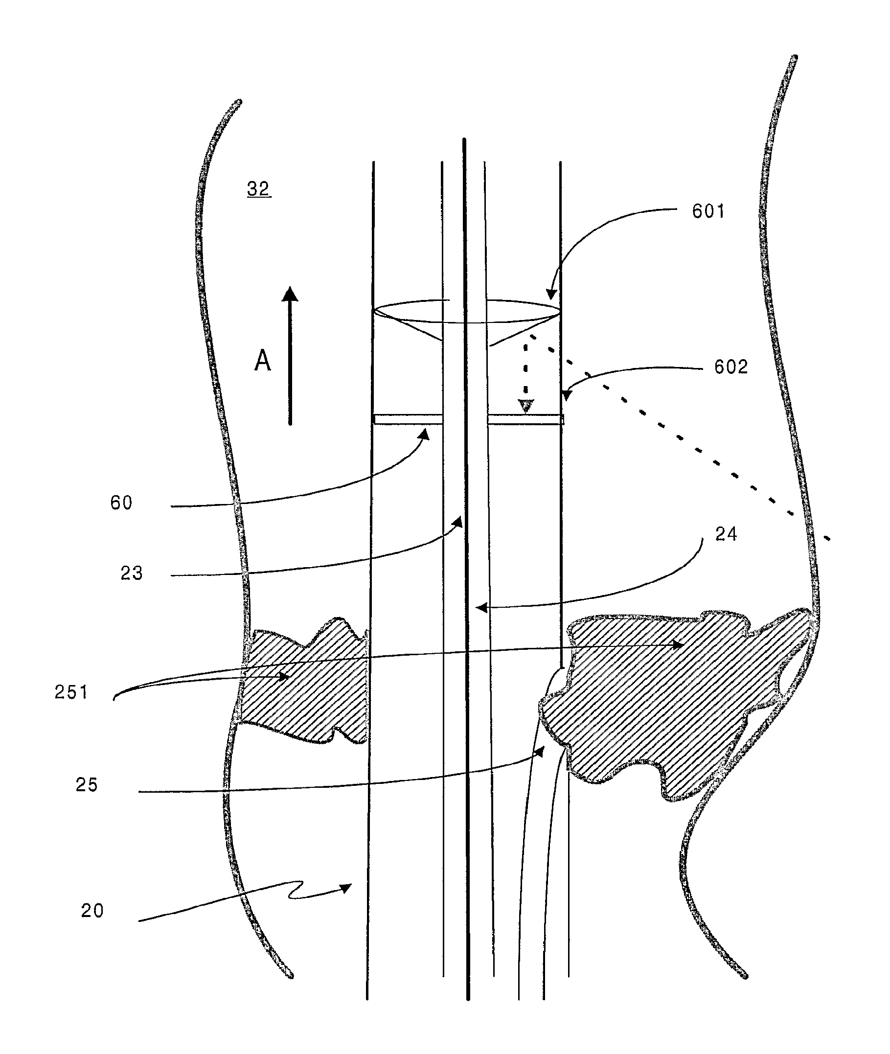
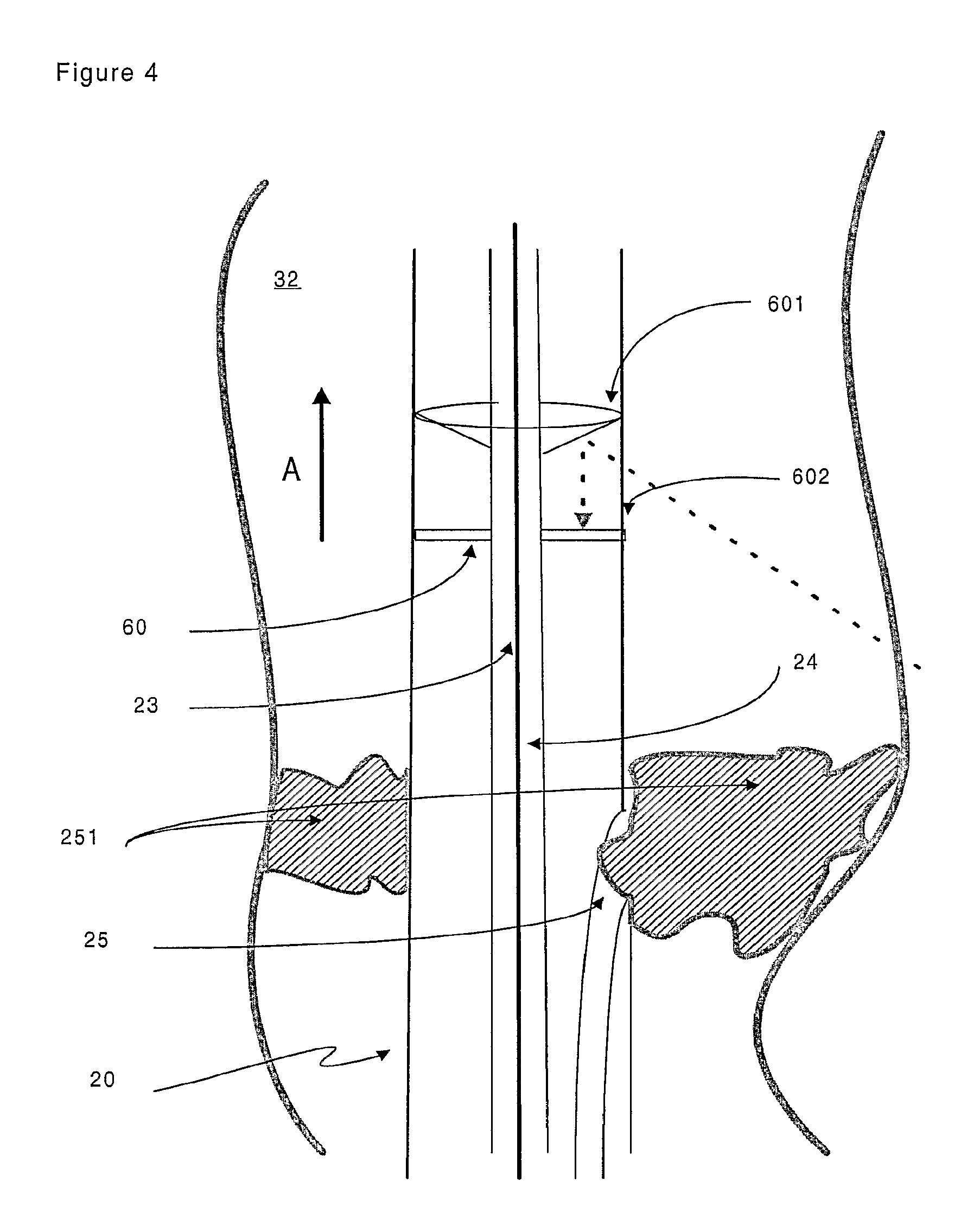
FIG. 4 is a representation of a specific embodiment of the target device of the invention. Arrow A shows the reversed direction of blood flow after an arterial-venous stenosis (also called PICVA) has been effected;
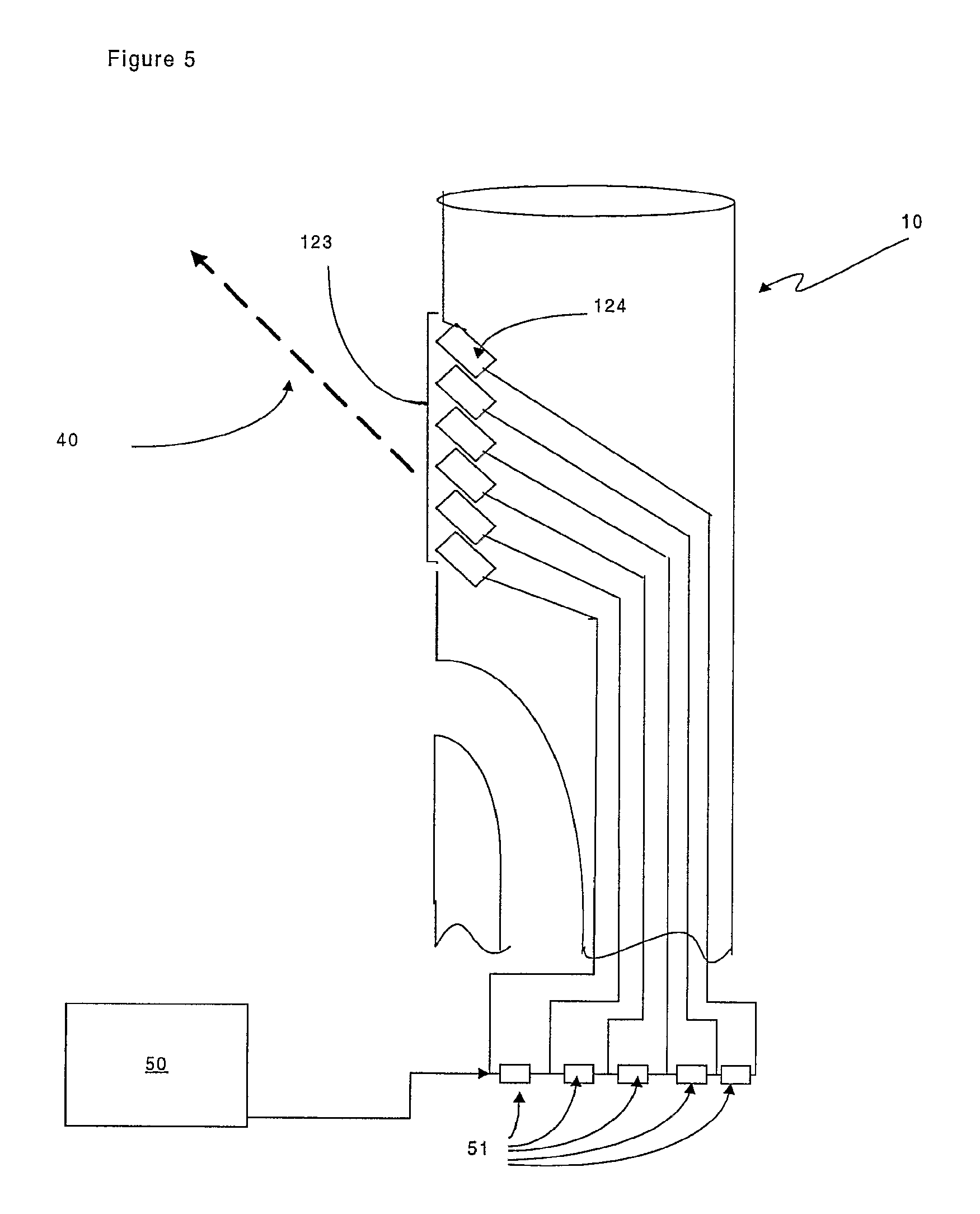
FIG. 5 is a representation of a specific embodiment of the launching device of the invention in which the signal transducer is comprised of an array of signal transducer elements;
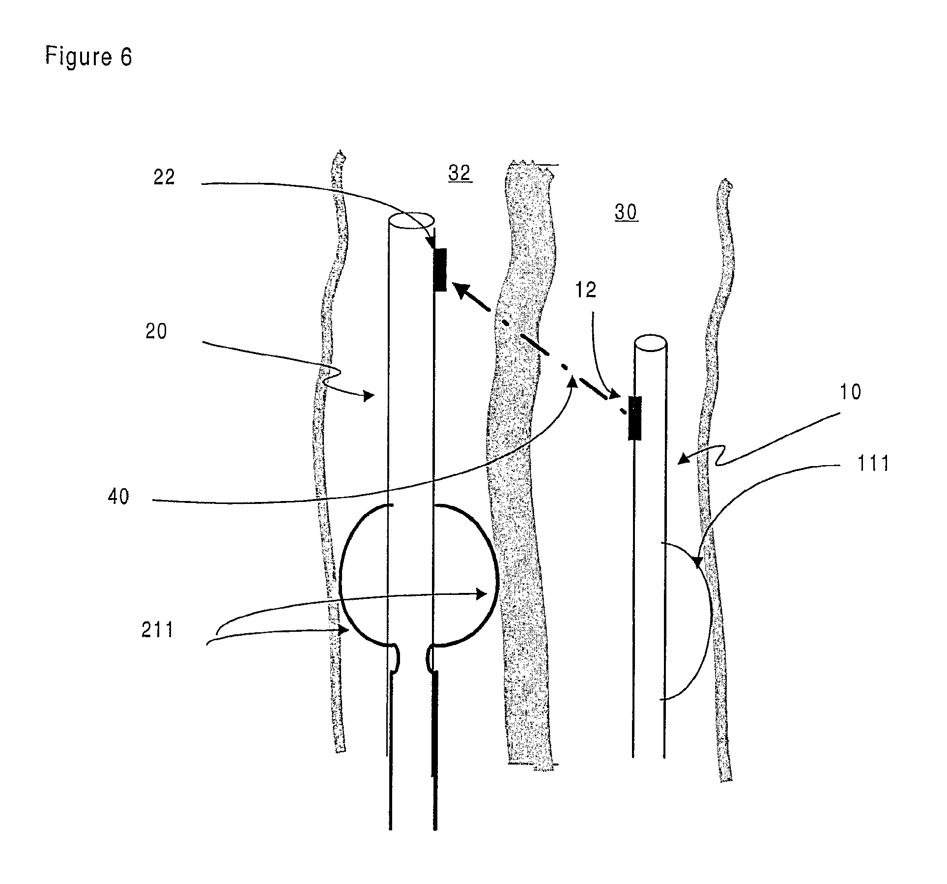
FIG. 6 is a representation of an embodiment of the invention wherein the launching and target devices comprise centring means;
FIG. 7 is a representation of a stent in place following a procedure such as arterial-venous stenosis. Interrupted arrow A shows the direction of blood flow through the stent between the first and second body cavities.
DETAILED DESCRIPTION OF THE INVENTION
In the embodiment of the invention as shown in FIG. 1, there is provided a launching device (10), which comprises a signal transmitter (12). The launching device (10) is typically a catheter that consists of an elongate flexible rod-like portion and a tip portion, and which provides a conduit for administering therapy within the body of a patient. Hence, the launching device (10) is suitable for location and movement through a first cavity or vessel (30) within a patient's body. The elongate portion of the launching device (10) comprises an outer sheath (11) that encloses a space, defining a lumen (13). The space within the lumen (13) may be suitably partitioned or subdivided as necessary so as to define channels for administering therapy or controlling the positioning of the launching device (10). Such subdivision may, for instance, be achieved either longitudinally or concentrically in an axial fashion.
A signal transducer (12) is located on the launching device (10). The signal transducer (12) provides a signal (40) that is directed outwards from the first launching device (10). In the embodiment shown in FIG. 1 the signal (40) is directed radially outward from the launching device (10) in a direction that is perpendicular to the longitudinal axis of the launching device (10). As mentioned in greater detail below, in alternative embodiments of the invention the direction of the signal (40) need not be perpendicular and can be directed at an angle to that of the axis of the launching device (10). The signal transducer (12) is, thus, comprised within the signal generating means of the apparatus of the invention.
The signal transducer (12) is connected to signal transmitter (50). The signal transmitted can be suitably selected from ultrasound or appropriate electromagnetic sources such as a laser, microwave radiation or via radio waves. In a specific embodiment of the invention described in further detail below, the signal transmitter (50) generates an ultrasound signal, which is relayed to the signal transducer (12), which in turn directs the signal (40) out of the body cavity (30) into the surrounding tissue.
According to the invention, a second device is located within an adjacent second body cavity or vessel (32). The first and second body cavities (30 and 32 respectively) are separated by intervening tissue (34), sometimes referred to as interstitial tissue or a septum. The first and second body cavities (30, 32) are located next to each other in a parallel fashion for at least a portion of their respective lengths. For example, many of the veins and arteries of the body are known to run in parallel with each other for at least a portion of their overall length.
The second device is the target device (20), which assumes a similar arrangement to that of the first device (10). The target device (20) can also be a catheter that consists of an elongate flexible rod-like portion and a tip portion, such that fine movement and positioning of the target device (20) within the body cavity (32) can be achieved. In common with the launching device (10) the target device (20) comprises an outer sheath (21) that encloses a space, defining a lumen (23). The lumen (23) can be suitably partitioned as with the launching device (10).
The target device (20) comprises a receiving transducer (22) for receiving the signal (40). The receiving transducer (22) is comprised within the signal detection means of the apparatus of the invention. In use, when the receiving transducer (22) receives the signal (40) transmitted from signal transducer (12), it transmits the received signal to signal detector (60). The signal detector (60) provides an output reading to the user of the apparatus via output display (61).
In this way, the transmission and detection of the directed signal (40) allows for the navigation and positioning of the launching device (10) relative to the target device (20). In use, the launching device (10) and target device (20) can be manoeuvred by the user of the apparatus until the output display (61) indicates that signal (40) is being received by the target device (40).
In a specific embodiment of the invention, the signal (40) is an ultrasound signal. The signal (40) is directional and is emitted by the signal transducer (12) in shape of a narrow cone or arc--i.e. with the width of the signal band increasing as the distance from the signal transducer (12) increases. Hence, the precision of alignment between the launching device (10) and the target device (20) depends not only upon signal detection but also upon the distance between the two devices, as at greater distances the signal bandwidth is also greater. This level of error is referred to as `positional uncertainty`. It will be appreciated that a certain level of tolerance exists for positional uncertainty, however, if therapy is to be directed with precision the amount of uncertainty should be minimised. For example, if the diameter (d) of the signal transducer (12) is 1 mm and the frequency of the ultrasound signal is 30 MHz, then the positional uncertainty (x)--i.e. the margin of error on either side of a centre line--will be 1 mm at a perpendicular separation of 5 mm between the launching and target devices (10, 20). For clinical applications of the invention, it is preferred that the positional uncertainty does not exceed around +/-5 mm (that is a total signal bandwidth of 10 mm at the point reception). More preferably, the positional uncertainty should be between around +/-0.01 mm and around +/-4.50 mm. Even more preferably, the positional uncertainty should be between around +/-0.1 mm and around +/-2 mm. Ideally, the positional uncertainty does not exceed around +/-1 mm.
The strength of the signal (40) will also be a determining factor and it will be appreciated that signal strength will diminish significantly as the distance between the launching device (10) and the target device (20) increases. This distance is in part determined by the amount of intervening tissue (34) between the two devices. By way of example, if the signal (40) is an ultrasound signal, it can be expected that significant deterioration of signal will occur where the launching device (10) and the target device (20) a separated by more than around 20 mm of solid tissue. Obviously, the density of the intervening tissue (34) will also have an effect upon the deterioration of signal (40) over distance.
The frequency of the desired ultrasound signal also determines the thickness of the signal transducer, which for a standard ultrasound ceramic transducer--such as a PZT--will be 0.075 mm at 30 MHz.
FIG. 2 shows a cross sectional view of the arrangement in FIG. 1, along the line BB. The correct orientation of the launching device relative to the target device is an important factor as it is this line of orientation (41) that determines where the therapy is to be applied. It will be understood by the skilled addressee that the clinical need for precisional placing of therapy in a patient necessitates a requirement for a directional signal (40) that is linked to the means for delivering therapy. In this way, the user of the apparatus of the invention can administer therapy to the correct location by ensuring that the launching device (10) and the target device (20) are correctly positioned via transmission and reception of the signal (40). Hence, the orientation line (41) denotes not only the direction of signal travel but also the path along which therapy can be administered to the patient.
An embodiment of the invention is shown in FIG. 3 in which the signal transducer (120) is oriented at an oblique angle relative to the longitudinal axis of the launching device (10). Hence, the signal (40) is transmitted at an angle that is in the direction of forward travel of the launching device (10) as it enters a body cavity (30). The preferred signal beam angle is between around 20.degree. and around 60.degree. to the perpendicular, more preferably between around 30.degree. and around 50.degree. to the perpendicular, and most preferably around 45.degree. to the perpendicular, when 0.degree. corresponds to the longitudinal axis of the launching device in the direction of travel.
The launching device (10) in FIG. 2, also shows an embodiment of the invention in which one means for administering therapy is provided. Launching device (10) comprises a hollow needle or cannula (17). The hollow needle (17) is located in an undeployed or retracted state within the lumen (13) of launching device (10). The hollow needle (17) may be deployed/extended from the launching device (10) at a time deemed appropriate by the user of the apparatus, via an aperture (16) in the outer sheath (11), The aperture (16), thus, can allow communication between the lumen (13) and the body cavity (30). It should be noted that the hollow needle (17) preferably travels along a path that is parallel to the direction of the signal (40) and is used to pierce the intervening tissue (34). In a preferred embodiment of the invention, the hollow needle makes a transit across the entirety of the intervening tissue (34) and in doing so allows the launching device (10) to access the second body cavity (32). If desired, the pathway made by the hollow needle (17) through the intervening tissue (34) can be subsequently widened to allow fluid communication between the first body cavity (30) and the second body cavity (32).
Therapeutic means suitable for use in the invention can comprise devices or instruments selected from the group consisting of a cannula; a laser; a radiation-emitting device; a probe; a drill; a blade; a wire; a needle and appropriate combinations thereof.
In a specific embodiment of the invention, the hollow needle (17) comprises a sensor (19) so as to assist further in determining positional information of the tip of the hollow needle relative to the launching device. In another specific embodiment of the invention the sensor (19) is capable of detecting changes in hydrostatic pressure. Other sensors that are suitable for use in the apparatus and methods of the invention can include temperature sensors, oxygenation sensors and/or colour sensors
Optionally, the hollow needle can further comprise an additional signal transducer (122). In the embodiment shown in FIG. 3 the signal transducer (122) is located near the tip of the hollow needle on the end of a guide wire (14). However, the signal transducer (122) can easily be located on the hollow needle if this is preferred. In use, the signal transducer (122) is driven with a short transmit pulse which produces a non-directional signal pulse. The signal pulse can be detected by the receiving transducer (23) mounted on the target device (20). From the time delay between the transmit pulse to the receipt of the signal pulse on the receiving transducer (23) the distance from the incoming guide wire (14) or hollow needle (17) to the receiving transducer (23) and hence the target device (20), can be determined.
As mentioned above, the target device (20) comprises a receiving transducer (22) for receiving the signal (40). The receiving transducer (22) can be unidirectional--i.e. capable of receiving a signal from one direction only--or omnidirectional--i.e. capable of receiving a signal from any direction. In the embodiment of the invention shown in FIG. 4, a target device (20) is located within a body cavity (32). The target device (20) comprises an omnidirectional ultrasound signal receiving transducer. A reflecting cone (601) directs the signal (40) onto a disc-shaped receiving transducer (60). An acoustically transparent window (602) separates the reflecting cone (601) from the receiving transducer (60). In an alternative embodiment, an omnidirectional ultrasound signal receiving transducer can be obtained by locating cylinder of a flexible piezoelectric material such as PVDF (polyvinyldifluoride) around the outer sheath of the target device (20). In such a way the cylinder acts in an equivalent manner to the receiving transducer (60).
FIG. 4 also shows an embodiment of the invention in which the target device (20) comprises a channel (25) for administering an agent, such as a therapeutic agent, to a patient. In a specific embodiment, the channel (25) functions as a conduit to allow application of a blocking material (251) that serves to obstruct or occlude the body cavity (32). The blocking material (251) can be suitably selected from a gel based substance. The placement of the blocking material (251) can be directed by movement of the target device (20). The presence of a guide member (24) within the lumen (23) of the target device (20) allows the user of the apparatus to precisely manipulate the position of the target device (20) as required. Alternative blocking materials (251) can include embolisation members (such as balloons) and self-expanding stents, for example.
The launching device (10) comprises a signal transducer (12) that is optionally oriented so that the signal (40) is transmitted at an angle as shown in FIG. 2. In an alternative embodiment of the invention, shown in FIG. 5, the signal transducer is in the form of a signal transducer array (123). The signal transducer array (123) comprises a plurality of signal transducer elements (124) which can be oriented collectively and thereby define the signal beam width and angle relative to the launching device (10). A further advantage of the embodiment shown in FIG. 5, is that the smaller size of the elements (124) means that the signal transducer does not occupy a significant proportion the lumen (13) of the launching device (10).
The embodiment in FIG. 5 is particularly suited to ultrasound beam-forming signalling. FIG. 5 shows an array of signal transducer elements (124) that are separately connected to the transmitter (50) via delays (51) so that the signals to each element are delayed relative to each other. The delays ensure that the ultrasound wavefronts from each element are aligned to produce a beam of ultrasound (40) at the requisite angle. In an alternative embodiment where the signal (40) is in the form of visible light, an array of LEDs can be used.
To assist in the process of alignment between the launching device (10) in the first body cavity (30) and the target device (20) in the second body cavity (32), a further embodiment of the invention provides for the devices to comprise means for centring the respective devices within the body cavities. In one embodiment the centring means comprises an inflatable bladder or balloon (111) which is located in the lumen (13, 23) when in an undeployed state and, when the device (10, 20) reaches the desired location within the patient, can be inflated. The balloon (111) can be annular in shape such that is surrounds the device (10, 20) in a doughnut-like fashion. The balloon (111) can also be arranged such that it inflates on only one or on two opposite sides of the device. In FIG. 6, an embodiment of the invention is shown where the balloon (111) is shown deploying on one side of the launching device (10).
Alternatively, in a further embodiment, the centring means is comprised of one or more loop structures (211). In this embodiment, the one or more loop structures (211) are located either in the lumen (13, 23) or within recesses made in the outer sheath (11, 21) when in an undeployed or retracted state. Hence, when the device (10, 20) reaches the desired location within the patient, the one or more loop structures (211) can be expanded outwardly from the device (10, 20), thereby, centring the device (10, 20) within the body cavity (30, 32). Outward expansion of the loop structures (211) can be suitably effected by compression of a length of wire, for example, such that it bows outwardly from the outer sheath (11, 21). A centring device that adopts this conformation typically comprises a plurality of compressible lengths of wire, or other suitable flexible material, arranged in parallel at radially spaced intervals around the periphery of the outer sheath (11, 21). Compression of the plurality of wires can be induced by way of a sliding member (not shown) located proximally and/or distally near to the ends of the plurality of wires. The sliding member is capable of translational movement along the longitudinal axis of the device (10, 20).
In FIG. 6, an embodiment of the invention is shown where the target device (20) comprises fully deployed centring means (211) that has allowed the target device (20) to be centred within the body cavity (32). Arrangements for centring the devices within the body cavities include, but are not limited to, expandable Chinese-lantern type devices, reversibly expandable stents, coils, helices and retractable probes or legs.
The invention is further illustrated by the following non-limiting example.
EXAMPLE
The methods and apparatus of the present invention demonstrate particular utility in cardio-vascular surgery. In the present example the apparatus of the invention is used by a clinician to perform the procedure of arterial-venous stenosis (PICVA) so as to enable retroperfusion of cardiac tissue following occlusion of a coronary artery.
The launching catheter (10) is inserted into the occluded coronary artery by standard keyhole surgical techniques. Likewise, the target catheter (20) is inserted into the coronary vein that runs parallel to the coronary artery. The coronary vein is not occluded and, therefore, provides an alternative channel for blood flow to the cardiac muscle effectively allowing the occlusion in the coronary artery to be bypassed.
The launching catheter (10) comprises a PZT ultrasound transducer (12) (CTS Piezoelectric Products, Albuquerque, New Mexico) that is oriented such that a directional ultrasound beam is transmitted at a 45.degree. angle (relative to the longitudinal axis of the launching device) in the direction of blood flow in the artery. The ultrasound transducer (12) is activated and a 30 MHz directional ultrasound signal (40) is transmitted from the launching catheter (10). The target catheter (20) comprises an omnidirectional ultrasound receiving transducer (60). To assist with localisation of both the launching and target catheters (10, 20), both catheters comprise centring means in the form of an annular inflatable balloon (111). The centring means on the launching catheter (10) is deployed by the clinician when the launching catheter (10) is deemed to be in an appropriate location close to the site of the occlusion within the coronary artery. This is typically determined via standard fluoroscopic imaging techniques. The target catheter (20) is then moved within the adjacent coronary vein until the directed ultrasound signal (40) is detected by the signal receiving transducer (60). To enable more precise alignment between the launching and target catheters (10, 20) the centring means (111) on the target catheter (20) can be deployed either before or after the signal (40) is detected.
On reception of the transmitted signal (40) the clinician can be certain that the launching and target catheters (10, 20) are correctly located within their respective blood vessels to allow for the arterial-venous stenosis procedure to commence. The target catheter (20) is used to block blood flow within the coronary vein via administration of a gel blocking material (251) though a channel (25) in the target catheter (10). The blocking material (251) is administered at a position downstream in terms of the venous blood flow relative to the location of the receiving signal transducer (60).
The clinician is then able to initiate arterial-venous stenosis by deploying a hollow needle (17) from the launching catheter (10) substantially along a path that is parallel and close to that taken by the ultrasound signal (40) though the intervening tissue (34) between the coronary artery and the coronary vein. The hollow needle (17) comprises a sensor means (19) near its tip that detects changes in hydrostatic pressure. Hence, the clinician is able to monitor the transition from arterial pressure to venous pressure as the hollow needle passes between the two vessels. The hollow needle (17) further comprises a guide member (14) in the form of a wire located in the bore of the needle. Once the hollow needle has been passed across the intervening tissue (34) it is retracted leaving the guide wire (14) in place. Alternatively, once the hollow needle (17) has made the transition across the intervening tissue (34) the clinician is able to pass the guide wire (14) through the bore of the needle and then retract the needle (17) into the launching catheter (10).
The clinician withdraws the launching catheter (10) from the patient leaving the guide wire (14) in place. A further catheter device is then slid along the guide wire (14) and an expandable stent (26) is deployed in order to widen the perforation in the intervening tissue (34) between the coronary artery and vein (see FIG. 7). The target catheter (20) is withdrawn from the patient leaving the blocking material (251) in position. Optionally, a further block or suture may be inserted into the coronary vein prevent reversal of arterial blood flow.
Hence, arterial blood is thereby diverted into the venous system and is enabled to retroperfuse the cardiac muscle tissue.
Whilst the specific example described above is restricted to the field of cardio-vascular surgery, it is envisaged that the present method and apparatus could have far reaching applications in other forms of surgery. For example, any surgery involving the need to direct therapy from one body cavity towards another adjacent body cavity could be considered. Hence, the present invention finds ready applications in the fields of neurosurgery, urology and general vascular surgery. In addition the type of therapy need not be restricted to formation of channels between body cavities. For instance, the apparatus and methods described herein are also of use in directing techniques such as catheter ablation, non-contact mapping of heart chambers and the delivery of medicaments to precise areas of the body.
Although particular embodiments of the invention have been disclosed herein in detail, this has been done by way of example and for the purposes of illustration only. The aforementioned embodiments are not intended to be limiting with respect to the scope of the appended claims, which follow. It is contemplated by the inventors that various substitutions, alterations, and modifications may be made to the invention without departing from the spirit and scope of the invention as defined by the claims.
NUMERALS USED IN THE FIGURES
TABLE-US-00001 10 Launching device 11 Outer sheath 111 Centring device 12 Signal transducer 120 Angled signal transducer 122 Needle mounted signal transducer 123 Signal transducer array 124 Signal transducer element 13 Lumen 14 Guide means 16 Aperture 17 Hollow needle 19 Pressure sensor 20 Target device 21 Outer sheath 211 Centring device 22 Receiving transducer 23 Lumen 24 Guide member 25 Channel 251 Blocking material 26 Stent 30 First body cavity 32 Second body cavity 34 Intervening tissue 40 Signal 41 Orientation direction 50 Signal transmitter 51 Transmitter delay 60 Signal detector 601 Reflecting cone 602 window 61 Output display
* * * * *
D00000
D00001
D00002
D00003
D00004
D00005
D00006
D00007
XML
uspto.report is an independent third-party trademark research tool that is not affiliated, endorsed, or sponsored by the United States Patent and Trademark Office (USPTO) or any other governmental organization. The information provided by uspto.report is based on publicly available data at the time of writing and is intended for informational purposes only.
While we strive to provide accurate and up-to-date information, we do not guarantee the accuracy, completeness, reliability, or suitability of the information displayed on this site. The use of this site is at your own risk. Any reliance you place on such information is therefore strictly at your own risk.
All official trademark data, including owner information, should be verified by visiting the official USPTO website at www.uspto.gov. This site is not intended to replace professional legal advice and should not be used as a substitute for consulting with a legal professional who is knowledgeable about trademark law.