System and method for preventing display bowing
Dunn , et al. A
U.S. patent number 10,398,066 [Application Number 15/964,258] was granted by the patent office on 2019-08-27 for system and method for preventing display bowing. This patent grant is currently assigned to Manufacturing Resources International, Inc.. The grantee listed for this patent is MANUFACTURING RESOURCES INTERNATIONAL, INC.. Invention is credited to Mike Brown, Marcos Diaz, William Dunn, Andrew Lincoln.


View All Diagrams
| United States Patent | 10,398,066 |
| Dunn , et al. | August 27, 2019 |
System and method for preventing display bowing
Abstract
An apparatus for preventing bowing of an electronic display includes a housing and a cover panel. The electronic display is located behind said cover panel, and a backlight is located behind said electronic display. A closed loop pathway for circulating gas includes a first gas pathway located between said cover panel and the electronic display, a backlight cavity located between the electronic display and the backlight, and a second gas pathway located behind the backlight.
| Inventors: | Dunn; William (Alpharetta, GA), Lincoln; Andrew (Alpharetta, GA), Brown; Mike (Cumming, GA), Diaz; Marcos (Alpharetta, GA) | ||||||||||
|---|---|---|---|---|---|---|---|---|---|---|---|
| Applicant: |
|
||||||||||
| Assignee: | Manufacturing Resources
International, Inc. (Alpharetta, GA) |
||||||||||
| Family ID: | 63917692 | ||||||||||
| Appl. No.: | 15/964,258 | ||||||||||
| Filed: | April 27, 2018 |
Prior Publication Data
| Document Identifier | Publication Date | |
|---|---|---|
| US 20180317350 A1 | Nov 1, 2018 | |
Related U.S. Patent Documents
| Application Number | Filing Date | Patent Number | Issue Date | ||
|---|---|---|---|---|---|
| 62491123 | Apr 27, 2017 | ||||
| Current U.S. Class: | 1/1 |
| Current CPC Class: | G06F 1/1601 (20130101); G02F 1/133385 (20130101); H05K 7/20972 (20130101); H05K 7/20963 (20130101); G02F 1/133308 (20130101); G02F 1/133603 (20130101); G02F 2001/133342 (20130101); G02F 2201/36 (20130101); G02F 2001/133628 (20130101); H05K 7/20145 (20130101) |
| Current International Class: | H05K 7/20 (20060101); G06F 1/16 (20060101); G02F 1/1333 (20060101); G02F 1/1335 (20060101) |
| Field of Search: | ;361/679.49-679.51,696 ;454/184 ;312/236 ;362/373,218,269,294 ;349/161 |
References Cited [Referenced By]
U.S. Patent Documents
| 4093355 | June 1978 | Kaplit et al. |
| 4593978 | June 1986 | Mourey et al. |
| 4634225 | January 1987 | Haim et al. |
| 4748765 | June 1988 | Martin |
| 4763993 | August 1988 | Vogeley et al. |
| 4921041 | May 1990 | Akachi |
| 4952783 | August 1990 | Aufderheide et al. |
| 4952925 | August 1990 | Haastert |
| 5029982 | July 1991 | Nash |
| 5088806 | February 1992 | McCartney et al. |
| 5132666 | July 1992 | Fahs |
| 5247374 | September 1993 | Terada |
| 5282114 | January 1994 | Stone |
| 5293930 | March 1994 | Pitasi |
| 5351176 | September 1994 | Smith et al. |
| 5432526 | July 1995 | Hyatt |
| 5535816 | July 1996 | Ishida |
| 5559614 | September 1996 | Urbish et al. |
| 5621614 | April 1997 | O'Neill |
| 5657641 | August 1997 | Cunningham et al. |
| 5748269 | May 1998 | Harris et al. |
| 5765743 | June 1998 | Sakiura et al. |
| 5767489 | June 1998 | Ferrier |
| 5808418 | September 1998 | Pitman et al. |
| 5818010 | October 1998 | McCann |
| 5818694 | October 1998 | Daikoku et al. |
| 5835179 | November 1998 | Yamanaka |
| 5864465 | January 1999 | Liu |
| 5869818 | February 1999 | Kim |
| 5869919 | February 1999 | Sato et al. |
| 5903433 | May 1999 | Gudmundsson |
| 5991153 | November 1999 | Heady |
| 6003015 | December 1999 | Kang et al. |
| 6007205 | December 1999 | Fujimori |
| 6089751 | July 2000 | Conover et al. |
| 6104451 | August 2000 | Matsuoka et al. |
| 6157432 | December 2000 | Helbing |
| 6181070 | January 2001 | Dunn et al. |
| 6191839 | February 2001 | Briley et al. |
| 6198222 | March 2001 | Chang |
| 6211934 | April 2001 | Habing et al. |
| 6215655 | April 2001 | Heady et al. |
| 6351381 | February 2002 | Bilski et al. |
| 6392727 | May 2002 | Larson et al. |
| 6417900 | July 2002 | Shin et al. |
| 6428198 | August 2002 | Saccomanno et al. |
| 6473150 | October 2002 | Takushima et al. |
| 6493440 | December 2002 | Gromatsky et al. |
| 6504713 | January 2003 | Pandolfi et al. |
| 6535266 | March 2003 | Nemeth et al. |
| 6628355 | September 2003 | Takahara |
| 6701143 | March 2004 | Dukach et al. |
| 6714410 | March 2004 | Wellhofer |
| 6727468 | April 2004 | Nemeth |
| 6812851 | November 2004 | Dukach et al. |
| 6825828 | November 2004 | Burke et al. |
| 6839104 | January 2005 | Taniguchi et al. |
| 6850209 | February 2005 | Mankins et al. |
| 6885412 | April 2005 | Ohnishi et al. |
| 6886942 | May 2005 | Okada et al. |
| 6891135 | May 2005 | Pala et al. |
| 6909486 | June 2005 | Wang et al. |
| 6943768 | September 2005 | Cavanaugh et al. |
| 6961108 | November 2005 | Wang et al. |
| 7015470 | March 2006 | Faytlin et al. |
| 7059757 | June 2006 | Shimizu |
| 7083285 | August 2006 | Hsu et al. |
| 7157838 | January 2007 | Thielemans et al. |
| 7161803 | January 2007 | Heady |
| 7190416 | March 2007 | Paukshto et al. |
| 7190587 | March 2007 | Kim et al. |
| 7209349 | April 2007 | Chien et al. |
| 7212403 | May 2007 | Rockenfeller |
| 7259964 | August 2007 | Yamamura et al. |
| 7269023 | September 2007 | Nagano |
| 7284874 | October 2007 | Jeong et al. |
| 7452121 | November 2008 | Cho et al. |
| 7457113 | November 2008 | Kumhyr et al. |
| 7480140 | January 2009 | Hara et al. |
| 7535543 | May 2009 | Dewa et al. |
| 7591508 | September 2009 | Chang |
| 7602469 | October 2009 | Shin |
| D608775 | January 2010 | Leung |
| 7667964 | February 2010 | Kang et al. |
| 7682047 | March 2010 | Hsu et al. |
| 7752858 | July 2010 | Johnson et al. |
| 7753567 | July 2010 | Kang et al. |
| 7800706 | September 2010 | Kim et al. |
| 7813124 | October 2010 | Karppanen |
| 7903416 | March 2011 | Chou |
| 7995342 | August 2011 | Nakamichi et al. |
| 8004648 | August 2011 | Dunn |
| 8035968 | October 2011 | Kwon et al. |
| 8081465 | December 2011 | Nishiura |
| 8102173 | January 2012 | Merrow |
| 8142027 | March 2012 | Sakai |
| 8208115 | June 2012 | Dunn |
| 8223311 | July 2012 | Kim |
| 8241573 | August 2012 | Banerjee et al. |
| 8248784 | August 2012 | Nakamichi et al. |
| 8254121 | August 2012 | Lee et al. |
| 8269916 | September 2012 | Ohkawa |
| 8270163 | September 2012 | Nakamichi et al. |
| 8274622 | September 2012 | Dunn |
| 8274789 | September 2012 | Nakamichi et al. |
| 8300203 | October 2012 | Nakamichi et al. |
| 8320119 | November 2012 | Isoshima et al. |
| 8351014 | January 2013 | Dunn |
| 8358397 | January 2013 | Dunn |
| 8369083 | February 2013 | Dunn et al. |
| 8373841 | February 2013 | Dunn |
| 8379182 | February 2013 | Dunn |
| 8400608 | March 2013 | Takahashi et al. |
| 8472174 | June 2013 | Idems et al. |
| 8472191 | June 2013 | Yamamoto et al. |
| 8482695 | July 2013 | Dunn |
| 8497972 | July 2013 | Dunn et al. |
| 8649170 | February 2014 | Dunn et al. |
| 8649176 | February 2014 | Okada et al. |
| 8654302 | February 2014 | Dunn et al. |
| 8678603 | March 2014 | Zhang |
| 8693185 | April 2014 | Dunn et al. |
| 8700226 | April 2014 | Schuch et al. |
| 8711321 | April 2014 | Dunn et al. |
| 8749749 | June 2014 | Hubbard |
| 8755021 | June 2014 | Hubbard |
| 8758144 | June 2014 | Williams et al. |
| 8760613 | June 2014 | Dunn |
| 8767165 | July 2014 | Dunn |
| 8773633 | July 2014 | Dunn et al. |
| 8804091 | August 2014 | Dunn et al. |
| 8823916 | September 2014 | Hubbard et al. |
| 8827472 | September 2014 | Takada |
| 8854572 | October 2014 | Dunn |
| 8854595 | October 2014 | Dunn |
| 8879042 | November 2014 | Dunn |
| 8988647 | March 2015 | Hubbard |
| 9030641 | May 2015 | Dunn |
| 9089079 | July 2015 | Dunn |
| 9119325 | August 2015 | Dunn et al. |
| 9119330 | August 2015 | Hubbard et al. |
| 9173322 | October 2015 | Dunn |
| 9173325 | October 2015 | Dunn |
| 9282676 | March 2016 | Diaz |
| 9285108 | March 2016 | Dunn et al. |
| 9313917 | April 2016 | Dunn et al. |
| 9370127 | June 2016 | Dunn |
| 9448569 | September 2016 | Schuch et al. |
| 9451060 | September 2016 | Bowers et al. |
| 9451733 | September 2016 | Dunn et al. |
| 9456525 | September 2016 | Yoon et al. |
| 9470924 | October 2016 | Dunn et al. |
| 9500896 | November 2016 | Dunn et al. |
| 9516485 | December 2016 | Bowers et al. |
| 9549490 | January 2017 | Hubbard |
| 9594271 | March 2017 | Dunn et al. |
| 9613548 | April 2017 | DeMars |
| 9622392 | April 2017 | Bowers et al. |
| 9629287 | April 2017 | Dunn |
| 9648790 | May 2017 | Dunn et al. |
| 9655289 | May 2017 | Dunn et al. |
| 9703230 | July 2017 | Bowers et al. |
| 9723765 | August 2017 | DeMars |
| 9797588 | October 2017 | Dunn et al. |
| 9801305 | October 2017 | Dunn et al. |
| 9823690 | November 2017 | Bowers et al. |
| 9835893 | December 2017 | Dunn |
| 9894800 | February 2018 | Dunn |
| 2001/0001459 | May 2001 | Savant et al. |
| 2001/0019454 | September 2001 | Tadic-Galeb et al. |
| 2002/0009978 | January 2002 | Dukach et al. |
| 2002/0033919 | March 2002 | Sanelle et al. |
| 2002/0050793 | May 2002 | Cull |
| 2002/0065046 | May 2002 | Mankins et al. |
| 2002/0084891 | July 2002 | Mankins et al. |
| 2002/0101553 | August 2002 | Enomoto et al. |
| 2002/0112026 | August 2002 | Fridman et al. |
| 2002/0126248 | September 2002 | Yoshia |
| 2002/0148600 | October 2002 | Bosch et al. |
| 2002/0149714 | October 2002 | Anderson et al. |
| 2002/0154255 | October 2002 | Gromatzky et al. |
| 2002/0164944 | November 2002 | Haglid |
| 2002/0164962 | November 2002 | Mankins et al. |
| 2002/0167637 | November 2002 | Burke et al. |
| 2003/0007109 | January 2003 | Park |
| 2003/0020884 | January 2003 | Okada et al. |
| 2003/0043091 | March 2003 | Takeuchi et al. |
| 2003/0104210 | June 2003 | Azumi et al. |
| 2003/0128511 | July 2003 | Nagashima et al. |
| 2003/0214785 | November 2003 | Perazzo |
| 2004/0012722 | January 2004 | Alvarez |
| 2004/0035558 | February 2004 | Todd et al. |
| 2004/0036622 | February 2004 | Dukach et al. |
| 2004/0036834 | February 2004 | Ohnishi et al. |
| 2004/0103570 | June 2004 | Ruttenberg |
| 2004/0105159 | June 2004 | Saccomanno et al. |
| 2004/0165139 | August 2004 | Anderson et al. |
| 2004/0223299 | November 2004 | Ghosh |
| 2005/0012039 | January 2005 | Faytlin et al. |
| 2005/0012722 | January 2005 | Chon |
| 2005/0062373 | March 2005 | Kim et al. |
| 2005/0073632 | April 2005 | Dunn et al. |
| 2005/0073639 | April 2005 | Pan |
| 2005/0134525 | June 2005 | Tanghe et al. |
| 2005/0134526 | June 2005 | Willem et al. |
| 2005/0213950 | September 2005 | Yoshimura |
| 2005/0229630 | October 2005 | Richter et al. |
| 2005/0237714 | October 2005 | Ebermann |
| 2005/0276053 | December 2005 | Nortrup et al. |
| 2005/0286131 | December 2005 | Saxena et al. |
| 2006/0012958 | January 2006 | Tomioka et al. |
| 2006/0018093 | January 2006 | Lai et al. |
| 2006/0034051 | February 2006 | Wang et al. |
| 2006/0056994 | March 2006 | Van Lear et al. |
| 2006/0082271 | April 2006 | Lee et al. |
| 2006/0092348 | May 2006 | Park |
| 2006/0125998 | June 2006 | Dewa et al. |
| 2006/0132699 | June 2006 | Cho et al. |
| 2006/0177587 | August 2006 | Ishizuka et al. |
| 2006/0199514 | September 2006 | Kimura |
| 2006/0209266 | September 2006 | Utsunomiya |
| 2006/0260790 | November 2006 | Theno et al. |
| 2006/0262079 | November 2006 | Seong et al. |
| 2006/0266499 | November 2006 | Choi et al. |
| 2006/0283579 | December 2006 | Ghosh et al. |
| 2007/0013647 | January 2007 | Lee et al. |
| 2007/0019419 | January 2007 | Hafuka et al. |
| 2007/0030879 | February 2007 | Hatta |
| 2007/0047239 | March 2007 | Kang et al. |
| 2007/0065091 | March 2007 | Hinata et al. |
| 2007/0076431 | April 2007 | Atarashi et al. |
| 2007/0103863 | May 2007 | Kim |
| 2007/0103866 | May 2007 | Park |
| 2007/0115686 | May 2007 | Tyberghien |
| 2007/0139929 | June 2007 | Yoo et al. |
| 2007/0140671 | June 2007 | Yoshimura |
| 2007/0151274 | July 2007 | Roche et al. |
| 2007/0151664 | July 2007 | Shin |
| 2007/0171353 | July 2007 | Hong |
| 2007/0206158 | September 2007 | Kinoshita et al. |
| 2007/0211205 | September 2007 | Shibata |
| 2007/0212211 | September 2007 | Chiyoda et al. |
| 2007/0217221 | September 2007 | Lee et al. |
| 2007/0237636 | October 2007 | Hsu |
| 2007/0267174 | November 2007 | Kim |
| 2008/0055534 | March 2008 | Kawano |
| 2008/0076342 | March 2008 | Bryant et al. |
| 2008/0099193 | May 2008 | Aksamit et al. |
| 2008/0148609 | June 2008 | Ogoreve |
| 2008/0209934 | September 2008 | Richards |
| 2008/0218446 | September 2008 | Yamanaka |
| 2008/0236005 | October 2008 | Isayev et al. |
| 2008/0267790 | October 2008 | Gaudet et al. |
| 2008/0283234 | November 2008 | Sagi |
| 2008/0285290 | November 2008 | Ohashi et al. |
| 2008/0310116 | December 2008 | O'Connor |
| 2009/0009729 | January 2009 | Sakai |
| 2009/0059518 | March 2009 | Kakikawa et al. |
| 2009/0065007 | March 2009 | Wilkinson et al. |
| 2009/0086430 | April 2009 | Kang et al. |
| 2009/0120629 | May 2009 | Ashe |
| 2009/0126906 | May 2009 | Dunn |
| 2009/0126907 | May 2009 | Dunn |
| 2009/0126914 | May 2009 | Dunn |
| 2009/0135365 | May 2009 | Dunn |
| 2009/0147170 | June 2009 | Oh et al. |
| 2009/0154096 | June 2009 | Iyengar et al. |
| 2009/0174626 | July 2009 | Isoshima et al. |
| 2009/0244472 | October 2009 | Dunn |
| 2009/0279240 | November 2009 | Karppanen |
| 2009/0302727 | December 2009 | Vincent et al. |
| 2009/0306820 | December 2009 | Simmons et al. |
| 2010/0060861 | March 2010 | Medin |
| 2010/0079949 | April 2010 | Nakamichi et al. |
| 2010/0162747 | July 2010 | Hamel et al. |
| 2010/0171889 | July 2010 | Pantel et al. |
| 2010/0182562 | July 2010 | Yoshida et al. |
| 2010/0220249 | September 2010 | Nakamichi et al. |
| 2010/0226091 | September 2010 | Dunn |
| 2010/0232107 | September 2010 | Dunn |
| 2010/0238394 | September 2010 | Dunn |
| 2010/0321887 | December 2010 | Kwon et al. |
| 2011/0001898 | January 2011 | Mikubo et al. |
| 2011/0013114 | January 2011 | Dunn et al. |
| 2011/0019363 | January 2011 | Vahlsing et al. |
| 2011/0051071 | March 2011 | Nakamichi et al. |
| 2011/0058326 | March 2011 | Idems et al. |
| 2011/0075361 | March 2011 | Nakamichi et al. |
| 2011/0083460 | April 2011 | Thomas et al. |
| 2011/0083824 | April 2011 | Rogers |
| 2011/0085301 | April 2011 | Dunn |
| 2011/0114384 | May 2011 | Sakamoto et al. |
| 2011/0116000 | May 2011 | Dunn et al. |
| 2011/0116231 | May 2011 | Dunn et al. |
| 2011/0122162 | May 2011 | Sato et al. |
| 2011/0141724 | June 2011 | Erion |
| 2011/0261523 | October 2011 | Dunn et al. |
| 2012/0006523 | January 2012 | Masahiro et al. |
| 2012/0012295 | January 2012 | Kakiuchi et al. |
| 2012/0012300 | January 2012 | Dunn et al. |
| 2012/0014063 | January 2012 | Weiss |
| 2012/0020114 | January 2012 | Miyamoto et al. |
| 2012/0038849 | February 2012 | Dunn et al. |
| 2012/0044217 | February 2012 | Okada et al. |
| 2012/0106081 | May 2012 | Hubbard et al. |
| 2012/0188481 | July 2012 | Kang et al. |
| 2012/0206687 | August 2012 | Dunn et al. |
| 2012/0249402 | October 2012 | Kang |
| 2012/0255704 | October 2012 | Nakamichi |
| 2012/0274876 | November 2012 | Cappaert et al. |
| 2012/0284547 | November 2012 | Culbert et al. |
| 2013/0170140 | July 2013 | Dunn |
| 2013/0173358 | July 2013 | Pinkus |
| 2013/0176517 | July 2013 | Kim et al. |
| 2013/0201685 | August 2013 | Messmore et al. |
| 2013/0258659 | October 2013 | Erion |
| 2013/0279154 | October 2013 | Dunn |
| 2013/0294039 | November 2013 | Chao |
| 2014/0044147 | February 2014 | Wyatt et al. |
| 2014/0085564 | March 2014 | Hendren et al. |
| 2014/0111758 | April 2014 | Dunn et al. |
| 2014/0113540 | April 2014 | Dunn et al. |
| 2014/0268657 | September 2014 | Dunn |
| 2014/0313698 | October 2014 | Dunn et al. |
| 2014/0314395 | October 2014 | Dunn et al. |
| 2015/0264826 | September 2015 | Dunn et al. |
| 2015/0319882 | November 2015 | Dunn et al. |
| 2015/0366101 | December 2015 | Dunn et al. |
| 2016/0041423 | February 2016 | Dunn |
| 2016/0044829 | February 2016 | Dunn |
| 2016/0192536 | June 2016 | Diaz |
| 2016/0195254 | July 2016 | Dunn et al. |
| 2016/0198588 | July 2016 | DeMars |
| 2016/0238876 | August 2016 | Dunn et al. |
| 2016/0242329 | August 2016 | DeMars |
| 2016/0242330 | August 2016 | Dunn |
| 2016/0249493 | August 2016 | Dunn et al. |
| 2016/0302331 | October 2016 | Dunn |
| 2017/0023823 | January 2017 | Dunn et al. |
| 2017/0068042 | March 2017 | Dunn et al. |
| 2017/0074453 | March 2017 | Bowers et al. |
| 2017/0083043 | March 2017 | Bowers et al. |
| 2017/0083062 | March 2017 | Bowers et al. |
| 2017/0111486 | April 2017 | Bowers et al. |
| 2017/0111520 | April 2017 | Bowers et al. |
| 2017/0111521 | April 2017 | Bowers et al. |
| 2017/0127579 | May 2017 | Hubbard |
| 2017/0140344 | May 2017 | Bowers et al. |
| 2017/0147992 | May 2017 | Bowers et al. |
| 2017/0163519 | June 2017 | Bowers et al. |
| 2017/0175411 | June 2017 | Bowers et al. |
| 2017/0188490 | June 2017 | Dunn et al. |
| 2017/0245400 | August 2017 | Dunn et al. |
| 2017/0257978 | September 2017 | Diaz |
| 2017/0332523 | November 2017 | DeMars |
| 2018/0042134 | February 2018 | Dunn et al. |
| 2018/0116073 | April 2018 | Dunn |
| 2011248190 | May 2011 | AU | |||
| 2014287438 | Jan 2018 | AU | |||
| 2015253128 | Mar 2018 | AU | |||
| 2705814 | Feb 2018 | CA | |||
| 2947524 | Apr 2018 | CA | |||
| 2702363 | May 2005 | CN | |||
| 107251671 | Oct 2017 | CN | |||
| 1408476 | Apr 2004 | EP | |||
| 1647766 | Apr 2006 | EP | |||
| 1762892 | Mar 2007 | EP | |||
| 1951020 | Jul 2008 | EP | |||
| 2225603 | Sep 2010 | EP | |||
| 2370987 | Oct 2011 | EP | |||
| 2603831 | Jun 2013 | EP | |||
| 2801888 | Nov 2014 | EP | |||
| 2909829 | Aug 2015 | EP | |||
| 3020260 | May 2016 | EP | |||
| 3117693 | Jan 2017 | EP | |||
| 3259968 | Dec 2017 | EP | |||
| 2402205 | Dec 2004 | GB | |||
| 402062015 | Mar 1990 | JP | |||
| 402307080 | Dec 1990 | JP | |||
| 3153212 | Jul 1991 | JP | |||
| H06-2337 | Jan 1994 | JP | |||
| 6082745 | Mar 1994 | JP | |||
| 8115788 | May 1996 | JP | |||
| 8194437 | Jul 1996 | JP | |||
| H08-305301 | Nov 1996 | JP | |||
| 8339034 | Dec 1996 | JP | |||
| H09246766 | Sep 1997 | JP | |||
| 11160727 | Jun 1999 | JP | |||
| H11296094 | Oct 1999 | JP | |||
| 2001209126 | Aug 2001 | JP | |||
| 2002158475 | May 2002 | JP | |||
| 2004053749 | Feb 2004 | JP | |||
| 2005017556 | Jan 2005 | JP | |||
| 2000131682 | May 2005 | JP | |||
| 2005134849 | May 2005 | JP | |||
| 2005265922 | Sep 2005 | JP | |||
| 2006513577 | Apr 2006 | JP | |||
| 2007322718 | May 2006 | JP | |||
| 2006148047 | Jun 2006 | JP | |||
| 2006163217 | Jun 2006 | JP | |||
| 2007003638 | Jan 2007 | JP | |||
| 2007-293105 | Nov 2007 | JP | |||
| 09307257 | Nov 2007 | JP | |||
| 2008010361 | Jan 2008 | JP | |||
| 2008292743 | Dec 2008 | JP | |||
| 2010024624 | Feb 2010 | JP | |||
| 2010-282109 | Dec 2010 | JP | |||
| 2017518526 | Jul 2017 | JP | |||
| 6305564 | Apr 2018 | JP | |||
| 200366674 | Nov 2004 | KR | |||
| 20050033986 | Apr 2005 | KR | |||
| 200401354 | Nov 2005 | KR | |||
| 20060016469 | Feb 2006 | KR | |||
| 100666961 | Jan 2007 | KR | |||
| 1020070070675 | Apr 2007 | KR | |||
| 1020070048294 | Aug 2007 | KR | |||
| 101764381 | Jul 2017 | KR | |||
| 10-1847151 | Apr 2018 | KR | |||
| 10-1853885 | Apr 2018 | KR | |||
| 2513043 | Apr 2014 | RU | |||
| WO2005079129 | Aug 2005 | WO | |||
| WO2007116116 | Oct 2007 | WO | |||
| WO2008050660 | May 2008 | WO | |||
| WO2009065125 | May 2009 | WO | |||
| WO2009065125 | May 2009 | WO | |||
| WO2009135308 | Nov 2009 | WO | |||
| WO2010007821 | Feb 2010 | WO | |||
| WO2010080624 | Jul 2010 | WO | |||
| WO2011069084 | Jun 2011 | WO | |||
| WO2011072217 | Jun 2011 | WO | |||
| WO2011140179 | Nov 2011 | WO | |||
| WO2011150078 | Dec 2011 | WO | |||
| WO2012021573 | Feb 2012 | WO | |||
| WO2012024426 | Feb 2012 | WO | |||
| 2013182733 | Dec 2013 | WO | |||
| WO2014149773 | Sep 2014 | WO | |||
| WO2014150036 | Sep 2014 | WO | |||
| WO2015168375 | Nov 2015 | WO | |||
| WO2016102982 | Jun 2016 | WO | |||
| WO2016133852 | Aug 2016 | WO | |||
| WO2017152166 | Sep 2017 | WO | |||
Other References
|
ITSENCLOSURES, Product Catalog, 2009, 48 pages. cited by applicant . ITSENCLOSURES, Standard Product Data Sheet, 2011, 18 pages. cited by applicant . SUNBRITETV, All Weather Outdoor LCD Television Model 4610HD, 2008, 1 page. cited by applicant . SUNBRITETV, Introduces Two New All-Weather Outdoor Televisions InfoComm 2008, 7 pages. cited by applicant . ITSENCLOSURES, Viewstation, 2017, 16 pages. cited by applicant . Novitsky, Driving LEDs versus CCFLs for LCD backlighting, Nov. 12, 2007, 6 pages. cited by applicant . Federman, Cooling Flat Panel Displays, 2011, 4 pages. cited by applicant . Zeeff, T.M., EMC analysis of an 18'' LCD monitor, 2000, 1 page. cited by applicant . Vertigo Digital Displays, Innovation on Display FlexVu Totem Brochure, 2014, 6 pages. cited by applicant . Vertigo Digital Displays, FlexVu Totem Shelter, 2017, 2 pages. cited by applicant . Vertigo Digital Displays, All Products Catalogue, 2017,14 pages. cited by applicant . Adnation,Turn Key Advertising Technology Solutions, May 23, 2017, 4 pages. cited by applicant . CIVIQ Smartscapes, FlexVue Ferro 55P/55L, Mar. 16, 2017, 4 pages. cited by applicant . Wankhede, Evaluation of Cooling Solutions for Outdoor Electronics, Sep. 17-19, 2007, 6 pages. cited by applicant . Bureau of Ships Navy Department, Guide Manual of Cooling methods for Electronic Equipment, Mar. 31, 1955, 212 pages. cited by applicant . CIVIQ, Invalidity Claim Charts, Appendix A-Appendix D, Jan. 24, 2018, 51 pages. cited by applicant . CIVIQ, Invalidity Contentions, Jan. 24, 2018, 51 pages. cited by applicant . Scott, Cooling of Electronic Equipment, Apr. 4, 1947, 119 pages. cited by applicant . Sergent, Thermal Management Handbook for Electronic Assemblies, Aug. 14, 1998, 190 pages. cited by applicant . Steinberg, Cooling Techniques for Electronic Equipment First Edition, 1980, 255 pages. cited by applicant . Steinberg, Cooling Techniques for Electronic Equipment Second Edition, 1991, 299 pages. cited by applicant . Yeh, Thermal Management of Microelectronic Equipment, Oct. 15, 2002, 148 pages. cited by applicant . CIVIQ, Invalidity Claim Chart, Appendix I, Mar. 22, 2018, 4 pages. cited by applicant . CIVIQ, Invalidity Claim Charts, Appendix F to H, Mar. 22, 2018, 18 pages. cited by applicant . Yung, Using Metal Core Printed Circuit Board as a Solution for Thermal Management article, 2007, 5 pages. cited by applicant . Mentley, David E., State of Flat-Panel Display Technology and Future Trends, Proceedings of the IEEE, Apr. vol. 90, No. 4, pp. 453-459. cited by applicant . Rohsenow, Warren M., Handbook of Heat Transfer, Third Edition, 1998, select chapters, 112 pages, McGraw-Hill. cited by applicant . The American Heritage College Dictionary, Third Edition, 1993, excerpt, 3 pages, Houghton Mifflin Company. cited by applicant . CIVIQ Smartscapes LLC. V Manufacturing Resources International, Inc., Petition for Inter Partes Review of U.S. Pat. No. 8,854,572 including Declaration of Greg Blonder in Support of Petition, Curriculum Vitae of Greg Blonder and Prosecution History of U.S. Pat. No. 8,854,572, Petition filed Mar. 14, 2018, 427 pages. cited by applicant . CIVIQ Smartscapes LLC. V Manufacturing Resources International, Inc., Defendant's Amended Answer and Countercliams to Plaintiff's First Amended Complaint, Filed Apr. 24, 2018, 240 pages. cited by applicant. |
Primary Examiner: Pape; Zachary
Attorney, Agent or Firm: Standley Law Group LLP Standley; Jeffrey S. Smith; Adam J.
Parent Case Text
CROSS-REFERENCE TO RELATED APPLICATION
This application claims the benefit of U.S. provisional patent application Ser. No. 62/491,123 filed Apr. 27, 2017, which is hereby incorporated by reference in its entirety.
Claims
What is claimed is:
1. An apparatus for preventing bowing of an electronic display comprising: a housing; a cover panel, wherein the electronic display is located behind said cover panel; a backlight located behind said electronic display; and a closed loop pathway for circulating gas comprising: a first gas pathway located between said cover panel and the electronic display; a backlight cavity located between the electronic display and the backlight; and a second gas pathway located behind the backlight; wherein the closed loop pathway is configured to cause the pressure of circulating gas in the backlight cavity to be lower than the circulating gas in the first gas pathway.
2. The apparatus of claim 1 further comprising: an open loop pathway for ambient air located behind said backlight.
3. The apparatus of claim 2 further comprising: a rear plate located behind said backlight; a corrugated layer extending between said rear plate and said backlight; and a first open loop pathway located between said backlight and said rear plate.
4. The apparatus of claim 3 further comprising: a heat exchanger located along the second gas pathway; and a second open loop pathway comprising said heat exchanger.
5. The apparatus of claim 2 further comprising: at least one circulating gas fan located within the second gas pathway for moving the circulating gas through the closed loop pathway; and at least one ambient air fan located within the open loop pathway for moving the ambient air through the open loop pathway.
6. The apparatus of claim 1 further comprising: a second cover panel; a second electronic display located behind said second cover panel; and a second backlight located behind said second electronic display; wherein the closed loop pathway for circulating gas further comprises: a third gas pathway located between said second cover panel and the second electronic display; and a second backlight cavity located between the second electronic display and the second backlight; wherein the second gas pathway is located between the backlight and the second backlight.
7. The apparatus of claim 6 wherein: the second cover panel, the second display assembly, and the second backlight are oriented in a back to back arrangement with the cover panel, the display assembly, and the backlight, respectively.
8. The apparatus of claim 1 further comprising: a first and second support located at an entrance and an exit, respectively, of the backlight cavity, wherein said first and second supports define an entrance gap and an exit gap, respectively, for the circulating gas to enter or exit the backlight cavity.
9. The apparatus of claim 8 wherein: the entrance gap is smaller than the exit gap.
10. The apparatus of claim 1 further comprising: a first and second bracket located at an entrance and an exit, respectively, of the backlight cavity, wherein said first and second brackets define an entrance gap and an exit gap, respectively, for the circulating gas to enter or exit the backlight cavity.
11. The apparatus of claim 10 wherein: the entrance gap is smaller than the exit gap.
12. The apparatus of claim 10 wherein: the second bracket comprises an angled section located on a distal end of said bracket and extending towards the side of said housing.
13. The apparatus of claim 12 wherein: the angled section is configured to create a venturi effect on circulating gas passing from the first gas pathway to the second gas pathway.
14. The apparatus of claim of 1 wherein: the pressure of the circulating gas passing through the backlight cavity is between 0 and 0.5 psi lower than the circulating gas passing through the first gas pathway.
15. An apparatus for preventing bowing of an electronic display comprising: a housing; a cover panel, wherein the electronic display is located behind, spaced apart from, and substantially parallel to said cover panel; a backlight located behind, spaced apart from, and substantially parallel to said electronic display, wherein the space between the backlight and the electronic display defines a backlight cavity; a closed loop pathway for circulating gas encircling the electronic display and comprising the space between said cover panel and said electronic display, the backlight cavity, and a space between said housing and said backlight; an open loop pathway located in the space between said housing and said backlight; a first and second bracket located at an entrance and an exit, respectively, of the backlight cavity, wherein said first and second brackets define an entrance gap and an exit gap, respectively, for the circulating gas to enter or exit the backlight cavity, wherein the entrance gap is smaller than the exit gap; an angled section located on a distal end of the second bracket and extending towards the side of said housing; and a first and second support located at the entrance and the exit, respectively, of the backlight cavity, wherein said first and second supports define a second entrance gap and a second exit gap, respectively, for the circulating gas to enter or exit the backlight cavity, wherein the second entrance gap is smaller than the second exit gap.
16. The apparatus of claim 15 wherein: the first and second brackets comprise a first set of apertures which define the entrance gap and the exit gap; and the first and second supports comprise a second set of apertures which define the second entrance gap and the second exit gap.
17. The apparatus of claim 15 wherein: the electronic display comprises liquid crystals; and the backlight comprises light emitting diodes.
18. An apparatus for preventing bowing of an electronic display comprising: a housing; a cover panel, wherein the electronic display is located behind said cover panel; a backlight located behind said electronic display and comprising a number of light emitting diodes; a closed loop pathway for circulating gas comprising: a first gas pathway located between said cover panel and the electronic display; a backlight cavity located between the electronic display and the backlight having an entrance and an exit; and a second gas pathway located behind the backlight and comprising a heat exchanger; a rear plate located behind said backlight; an open loop pathway comprising: first open loop pathway located in the space between said rear plate and said backlight; and a second open loop pathway comprising said heat exchanger; a first and second bracket located at the entrance and the exit, respectively, of the backlight cavity, wherein said first and second brackets comprise a first number of apertures defining an entrance gap and an exit gap, respectively, for the circulating gas to enter or exit the backlight cavity, wherein the entrance gap is smaller than the exit gap; an angled section located on a distal end of said second bracket and extending towards the side of said housing; and a first and second support located at the entrance and the exit, respectively, of the backlight cavity, wherein said first and second supports comprise a second number of apertures defining a second entrance gap and a second exit gap, respectively, for the circulating gas to enter or exit the backlight cavity, wherein the second entrance gap is smaller than the second exit gap.
Description
TECHNICAL FIELD
Exemplary embodiments of the present invention relate generally to assemblies for electronic displays.
BACKGROUND AND SUMMARY OF THE INVENTION
Electronic displays have grown in popularity not only for indoor use, but also for outdoor use. One exemplary application, without limitation, is the digital out of home market where the electronic displays are increasingly replacing the use of static posters. The use of electronic displays is advantageous because they allow images to be changed quickly as well as permit the use videos and interactive displays, among other benefits. Such displays may be used for advertisements, public announcements, information, wayfinding, and the like.
Such outdoor, and some indoor, displays are sometimes encased in a housing to protect them from environmental conditions. The housing may be designed to resist, mitigate, manage, control, or prevent water, precipitation, dust, and air contaminant intrusion, vandalism, tampering, wind, temperature changes, solar loading, extreme temperatures, and the like. Oftentimes, these displays are placed outdoors where they are subject to extreme temperatures, drastic temperature changes, and significant solar loading. If the temperature inside the housing gets too high or too low the electronic displays and related components may be damaged. As such, the temperature inside the housing must be maintained at acceptable levels. In order to maintain the temperature inside the housings at acceptable levels, a number of gas pathways are generally placed through the housing. Sometimes, a combination of open loops carrying ambient air and closed loops carrying circulating gas are used.
Over time, the market has demanded increasingly larger displays. These larger displays have correspondingly larger surface areas and often require correspondingly larger, in size or number, gas pathways to maintain the temperature in the housing. As the dimensions of these displays and corresponding gas pathways have increased, the potential for the displays to bow outwardly has increased. This is because, typically, the displays are mostly unsupported. The displays are generally mounted along their perimeter so illumination from the backlight is permitted to reach the entirety of the display, among other considerations. Thus, a large section of the display is not directly mounted to a housing or other stabilizing or supporting structure, which may allow bowing of the display. Additionally, the asymmetrical temperature loading of various layers and components of the display may contribute to such display bowing. Further still, some displays have a gap between the electronic display itself and a cover panel located in front of the electronic display. As the electronic display bows towards the cover panel, the gap between the cover panel and the display may be narrowed and a resulting venturi effect may be created. The venturi effect may increase the bowing forces.
Such bowing can cause damage to the display, distortion of the displayed image, and may disrupt airflow through the open and closed loops. In some cases, the electronic display may bow outwardly enough that it contacts the cover panel. This may not only interrupt normal thermal management but may also result in significant heat transfer from the solar loaded cover panel to the electronic display. This may rapidly cause permanent damage to the display. Therefore, what is needed is a system and method for preventing an electronic display from bowing.
Additionally, display assemblies comprising a backlight sometimes have a sealed cavity for the backlight. As the illumination devices and other components of the backlight generate heat, heat can become trapped in this cavity. Because the cavity may be completely or partially sealed, the heat may build up and cause damage to components of the assembly. Therefore, what is needed is a system and method for removing heat from the backlight cavity.
The present invention is a system and method for preventing an electronic display from bowing. The present invention is also a system and method for removing heat from the backlight cavity. The present invention provides a first gas pathway through first gas pathways between a cover panel and an electronic display and an additional flow path through a backlight cavity located in the space between the electronic display and a backlight. The flow of air through the backlight cavity removes heat from the backlight cavity generated by the illumination devices or other components.
The amount or speed of airflow through the first gas pathway and the backlight cavity may be controlled so as to create a pressure drop in the backlight cavity as compared to the first gas pathway. This pressure drop may result in forces which tend to pull the electronic display away from the cover panel, thereby reducing or eliminating the bowing. In particular, a support or a bracket may be used to create an entrance gap and exit gap into and out of the backlight cavity. In this way the amount or speed of airflow through the backlight cavity may be controlled. The entrance gap may be smaller than the exit gap. In exemplary embodiments, an angled section may extend from the distal end of the bracket located near the exit gap. The angled section may extend towards the side of the housing to restrict the flow of air from the first gas pathway into a second gas pathway located behind the backlight. The constriction of this air may create a venturi effect, creating a low-pressure zone near the angled section to pull circulating gas through the backlight cavity.
BRIEF DESCRIPTION OF THE DRAWINGS
In addition to the features mentioned above, other aspects of the present invention will be readily apparent from the following descriptions of the drawings and exemplary embodiments, wherein like reference numerals across the several views refer to identical or equivalent features, and wherein:
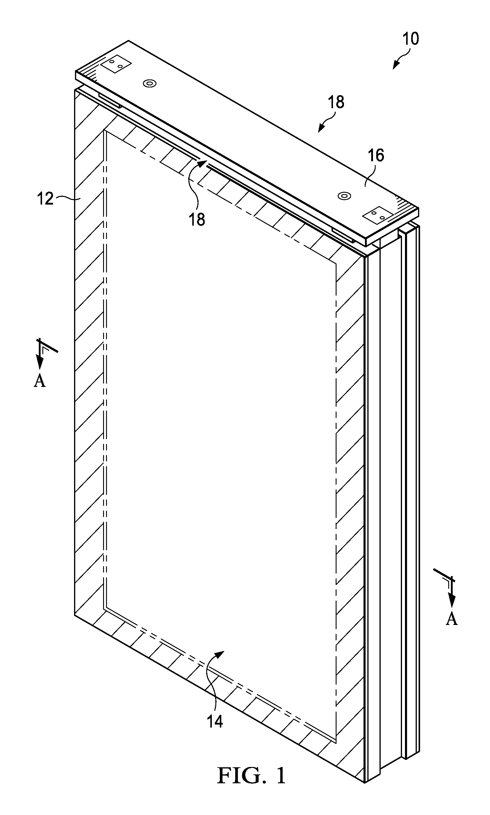
FIG. 1 is a perspective view of an exemplary display assembly in accordance with the present invention also indicating section lines A-A;
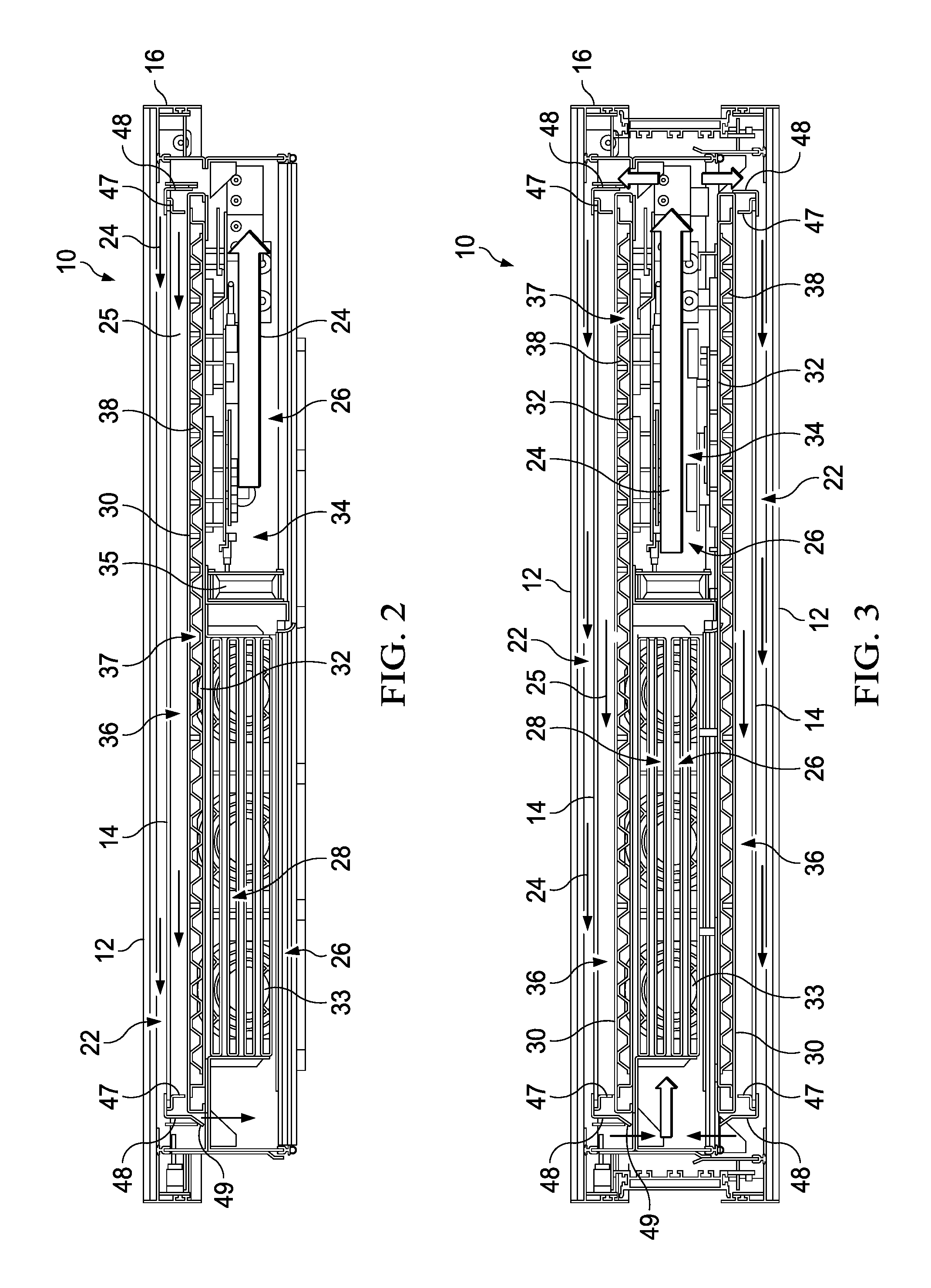
FIG. 2 is a top sectional view of an exemplary display assembly embodiment taken along section line A-A of FIG. 1;
FIG. 3 is a top sectional view of another exemplary display assembly embodiment taken along section line A-A of FIG. 1;
FIG. 4 is a top section view similar to FIG. 2 illustrating an exemplary pressure analysis where the display bowing is reduced or eliminated;
FIG. 5 is a top section view similar to FIG. 3 illustrating another exemplary pressure analysis where the display bowing is reduced or eliminated;
FIG. 6 is an exemplary graphical representation of another exemplary pressure analysis;
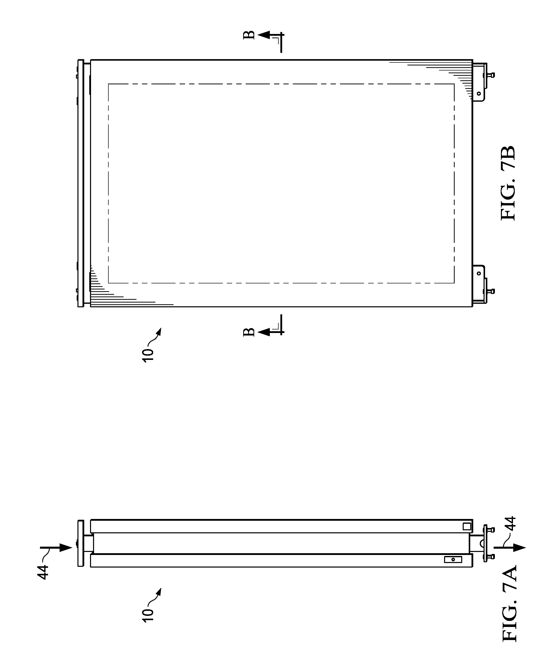
FIG. 7A is a side view of another exemplary display assembly in accordance with the present invention;
FIG. 7B is a front view of the display assembly of FIG. 7A also indicating section line B-B;
FIG. 8 is a top sectional view taken along section line B-B of FIG. 7B also indicating detail A;
FIG. 9 is a detailed top sectional view of Detail A of FIG. 8;
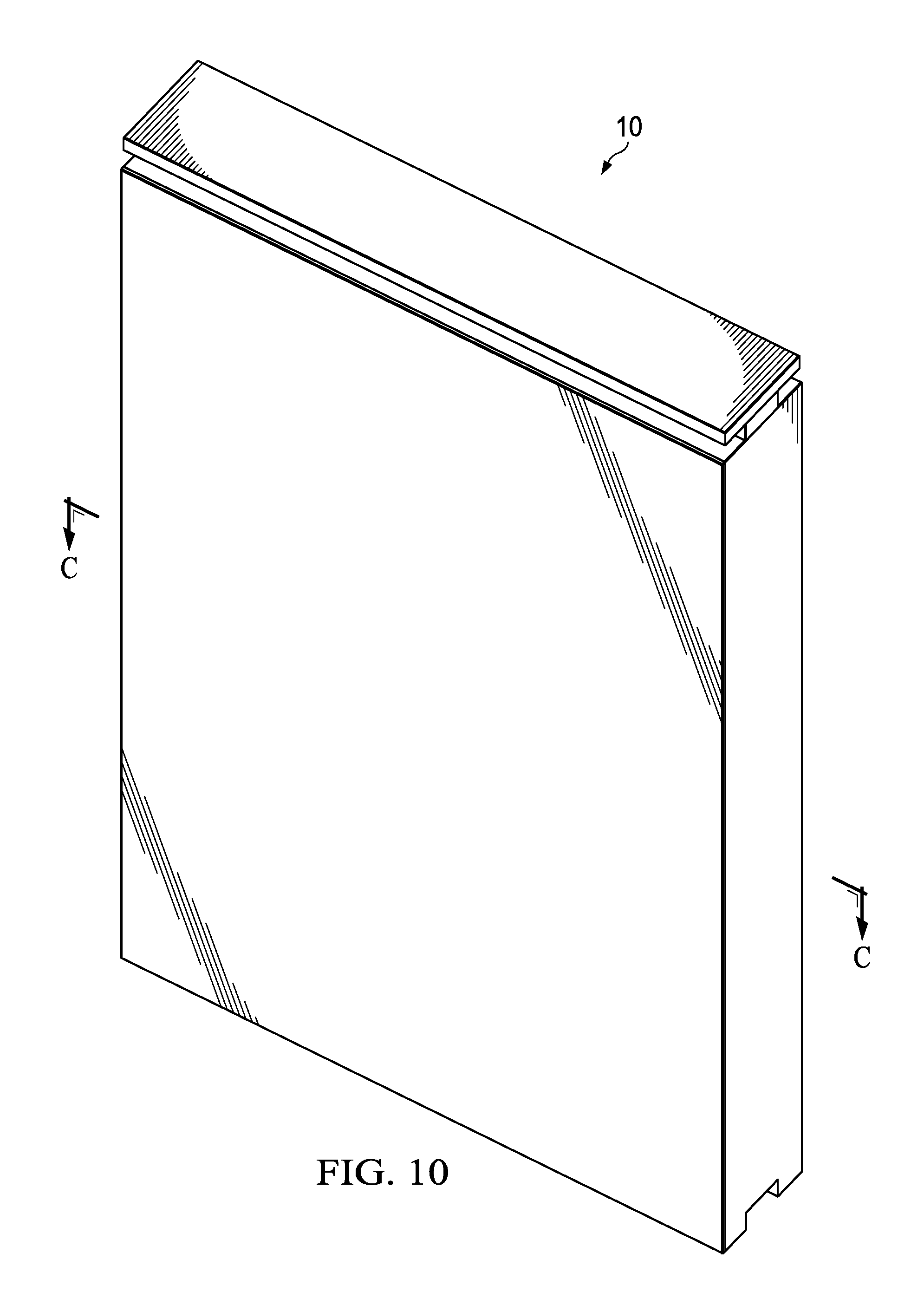
FIG. 10 is a front perspective view of another exemplary display assembly in accordance with the present invention also indicating section line C-C;
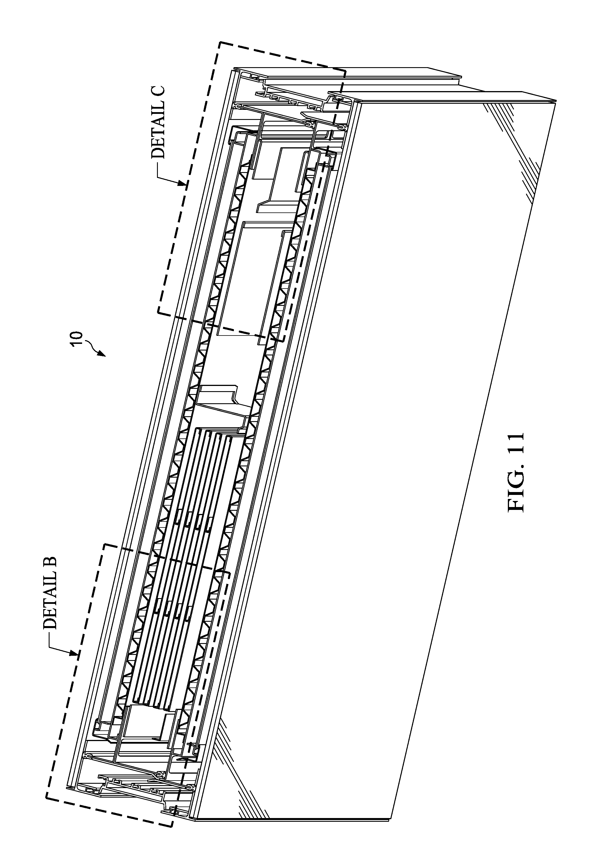
FIG. 11 is a top perspective sectional view taken along section line C-C of FIG. 10 also indicating Detail B and Detail C;
FIG. 12 is a detailed top sectional perspective view of Detail B of FIG. 11;
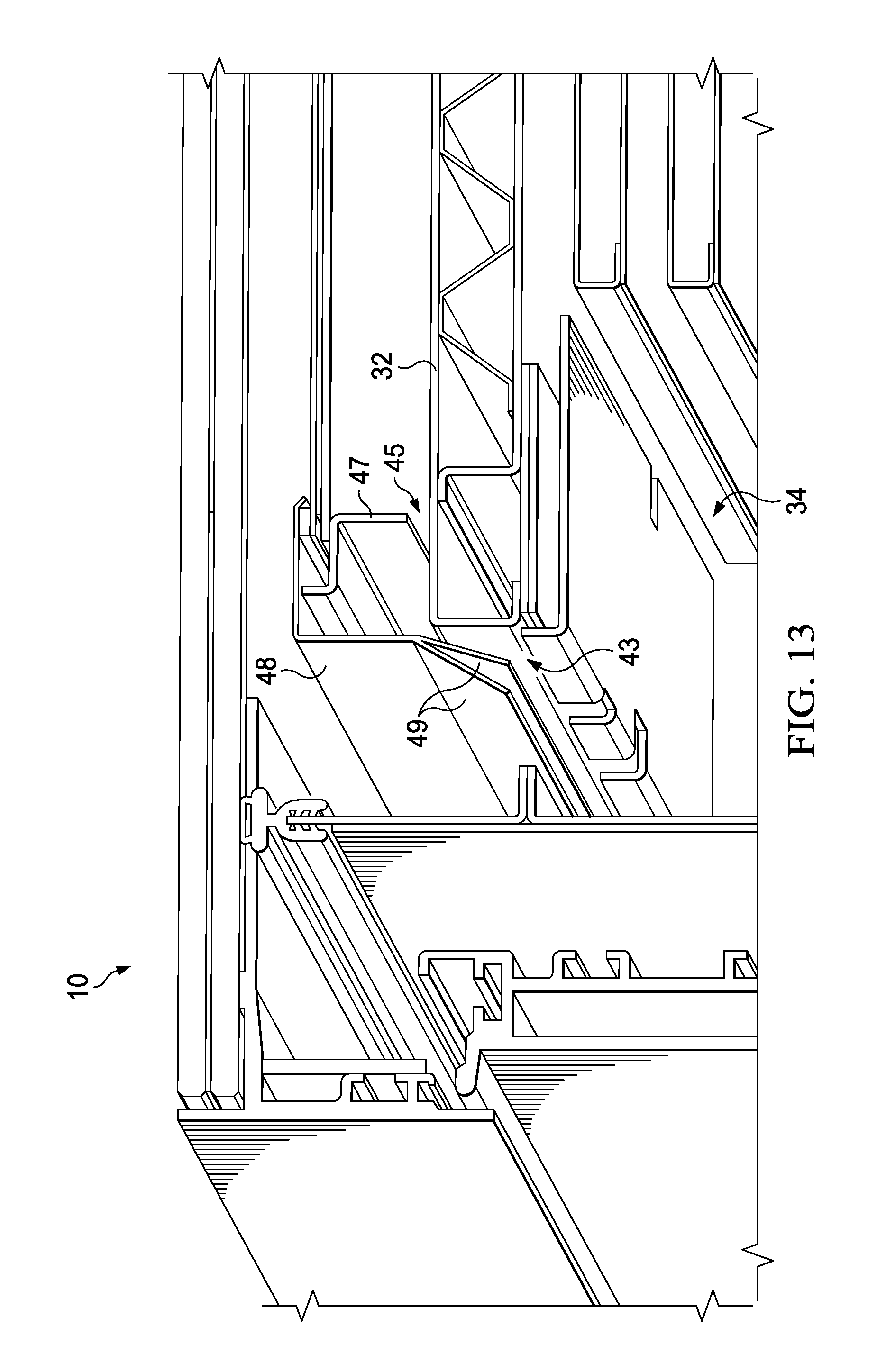
FIG. 13 provides another angle of Detail B of FIGS. 11-12;
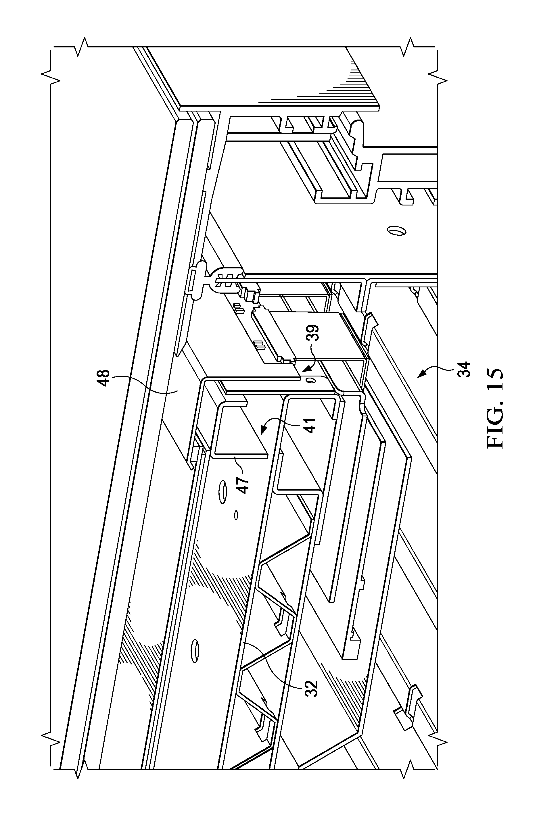
FIG. 14 is a detailed top perspective sectional view of Detail C of FIG. 11;
FIG. 15 is a detailed top perspective sectional view similar to FIG. 14 illustrated in greater detail and from a different angle;
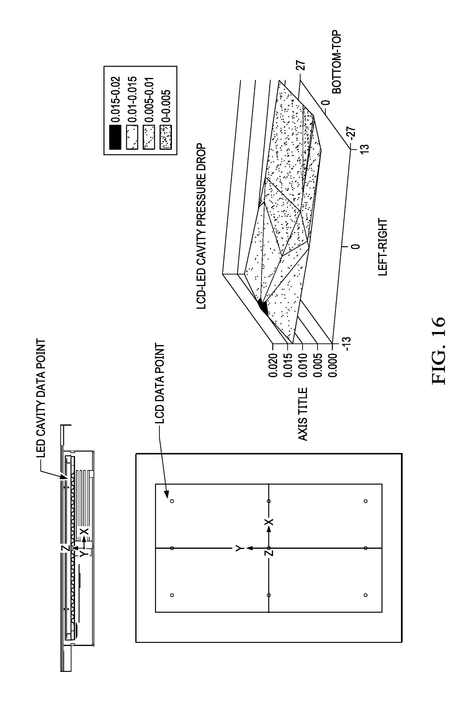
FIG. 16 is another exemplary pressure analysis similar to FIG. 6;
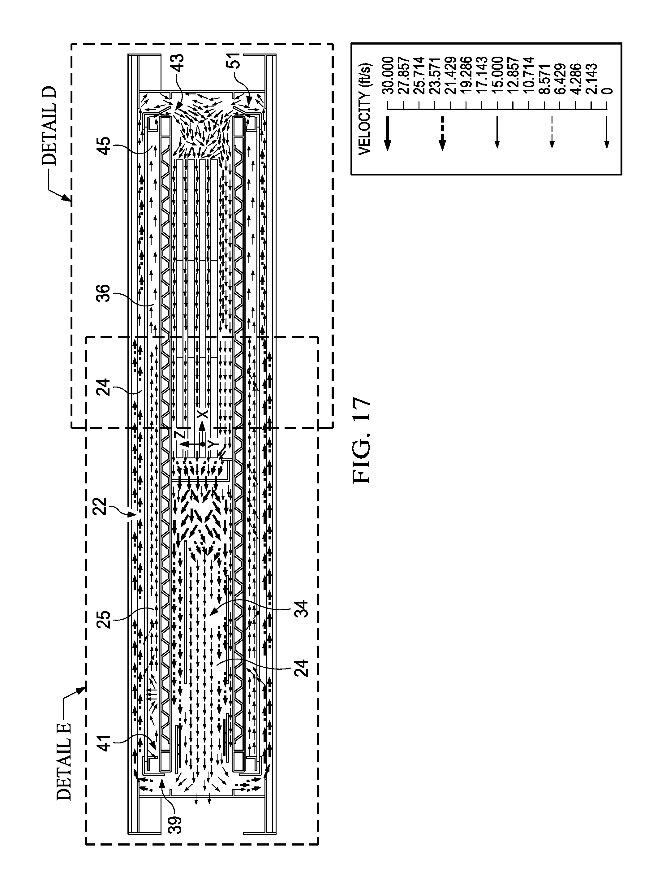
FIG. 17 is a top sectional view similar to FIG. 11 showing an exemplary air flow velocity analysis also indicating Detail D and Detail E;
FIG. 18 is a detailed top sectional view of Detail D of FIG. 17; and
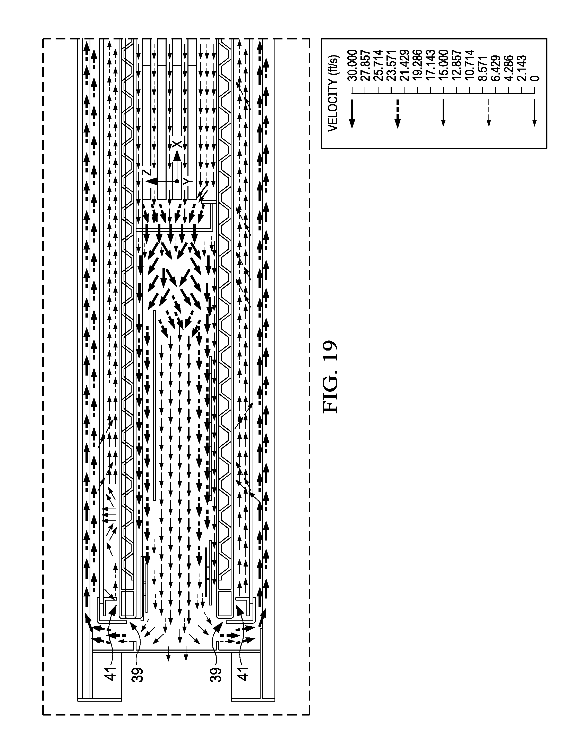
FIG. 19 is a detailed top sectional view of Detail E of FIG. 17.
DETAILED DESCRIPTION OF EXEMPLARY EMBODIMENT(S)
Various embodiments of the present invention will now be described in detail with reference to the accompanying drawings. In the following description, specific details such as detailed configuration and components are merely provided to assist the overall understanding of these embodiments of the present invention. Therefore, it should be apparent to those skilled in the art that various changes and modifications of the embodiments described herein can be made without departing from the scope and spirit of the present invention. In addition, descriptions of well-known functions and constructions are omitted for clarity and conciseness.
FIG. 1 is a perspective view of an exemplary display assembly 10 in accordance with the present invention also indicating section line A-A. The display assembly 10 may comprise an electronic display 14 located in a housing 16. In exemplary embodiments, the electronic display 14 is a liquid crystal display (LCD). However, any type of electronic display 14 may be used, such as but not limited to, a LCD, light emitting diode (LED) display, organic LED display, plasma display, or the like. The electronic display 14 may optionally comprise one or more diffuser sheets or optical films. A cover panel 12 may be located in front of the electronic display 14. The cover panel 12 may be located substantially parallel to, spaced apart from, and in front of the electronic display 14. The cover panel 12 may form the front surface of the housing 16. The cover panel 12 may be comprised or a transparent or translucent material such as, but not limited to, a glass or acrylic. The cover panel 12 may be comprised or multiple layers. As will be shown and described in greater detail herein, one or more electronic displays 14 and corresponding components may be used, including but not limited to, a pair of electronic displays 14 placed back to back within the housing 16. Regardless, an intake 18 may extend along either side or the upper portion of the housing 16, though any location is contemplated. As will be shown and described in greater detail herein, an exhaust 20 may be located along the lower edge of the display assembly 10, though any location is contemplated.
FIG. 2 is a top section view taken along section line A-A of FIG. 1 illustrating an exemplary display assembly 10 using a single electronic display 14. A backlight 30 may be located behind the electronic display. The backlight 30 may be located behind, substantially parallel to, and spaced apart from, the electronic display 14. The backlight 30 may comprise a number of illumination devices, such as but not limited to light emitting diodes (LEDs), located on a pan. In exemplary embodiments, the backlight 30 may comprise a number of illumination devices arranged in a spaced pattern to provide a directly backlit arrangement. In other exemplary embodiments, the backlight 30 may comprise a number of illumination devices arranged in a line along one or more sides of the electronic display 14 in an edge lit arrangements. In still other exemplary embodiments, the backlight 30 may form a part of the electronic display 14, such as without limitation with an organic LED display. In such embodiments, a backlight pan may be located behind the electronic display 14. The backlight pan may be a metal sheet or the like.
Regardless, a rear plate 32 may be located behind the backlight 30. The rear plate 32 may be located behind, spaced apart from, and substantially parallel to the backlight 30. A first gas pathway 22 may be located in the space between the rear surface of the cover panel 12 and the front surface of the electronic display 14. This space may also be referred to as the LCD cavity herein. The first gas pathway 22 may be configured to receive circulating gas 24. The circulating gas 24 may travel through the first gas pathway 22 and into a second gas pathway 26 located behind the backlight 30.
The second gas pathway 26 may be located in the space between the rear plate 32 and the rear of the housing 16. The second gas pathway 26 may comprise a heat exchanger 28 and an electronics cavity 30, though such is not required. The heat exchanger 28 may be any type of heat exchanger 28. The heat exchanger 28 may be mounted to the rear plate 32, though any location is contemplated. In exemplary embodiments, the heat exchanger 28 occupies a first portion of the second gas pathway 26 and the electronics cavity 34 occupies a second portion where various electronic components may be located. The heat exchanger 28 may also be part of a second open loop pathway. These various electronic components may be used to operate the display assembly 10. After traveling through the second gas pathway 26, the circulating gas 24 may return to the first gas pathway 22, thus creating a closed loop. Stated another way, the closed loop may encircle the electronic display 14. One or more closed loop fans 35 may be placed along the closed loop so as to control the speed and amount of circulating gas 24 pass through the closed loop, or through the first gas pathway 22 or the second gas pathway 26. In exemplary embodiments, the closed loop fan 35 may be located between the heat exchanger 28 and the electronics cavity 34, though any location is contemplated.
In exemplary embodiments, a corrugation layer 38 may be located between the rear surface of the backlight 30 and the front surface of the rear plate 32. The corrugation layer 38 may be configured to receive ambient air 44. The space between the rear plate 32 and the backlight 30 may define a first open loop channel 37. The ambient air 44 may also flow through the heat exchanger 28 (the second open loop pathway). Ambient air 44 may enter the assembly 10, pass through the first or second open loop pathways and then exit the assembly 10, thus creating an open loop. One or more open loop fans 33 may be placed along the open loop to control the amount or speed of ambient air 44 flowing through the open loop, or through the corrugation layer 38 or the heat exchanger 28.
A backlight cavity 36 may be located in the space between the rear surface of the electronic display 14 and the front surface of the backlight 30. A portion of the circulating gas 24 may be separated from the remainder of the circulating gas 24 and travel into or through the backlight cavity 36. This portion of the circulating gas 24 may also be referred to herein as the backlight cavity gas 25. The backlight cavity gas 25 that exits the backlight cavity 36 may be rejoined with the circulating gas 24. The backlight cavity 36 may be framed on the sides, at least in part, by supports 47. In exemplary embodiments, a first supports 47 is located on the side of the backlight cavity 36 which receives the backlight cavity gas 25 and a second support 47 is located on the side of the backlight cavity 36 where the backlight cavity gas 25 exits the backlight cavity 36.
The supports 47 may extend from the rear surface of the electronic display 14 to support various components, such as but not limited to, a diffuser, optical films, a transparent sheet, or the like, located between the electronic display 14 and the backlight 30. The supports 47 may be spaced apart from the backlight 30 or the electronic display 14 at one or more locations to define an entrance gap and an exit gap for the backlight cavity gas 25 to enter or exit the backlight cavity 36, respectively. In other exemplary embodiments, the supports 47 may comprise a number of aperture which define the entrance gap and the exit gap. As will be explained in greater detail herein, the backlight cavity gas 25 may be maintained at a lower pressure relative to the circulating gas 24 traveling through the first gas pathway 22, though such is not required.
In exemplary embodiments, the pressure of the backlight cavity gas 25 may be kept relatively low by controlling the amount or speed of the backlight cavity gas 25 permitted to enter and exit the backlight cavity 36. The amount or speed of the backlight cavity gas 25 may be controlled, at least in part, by the dimensions and/or shape of the backlight cavity 36. In exemplary embodiments, the gap between the supports 47 and the front surface of the backlight 30 may be sized and configured to control the amount or speed of the backlight cavity gas 25 allowed to enter and exit the backlight cavity 36. In exemplary embodiments, the gap between the support 47 located at the entrance to the backlight cavity 36 may be smaller than the gap between the support 47 located at the exit of the backlight cavity 36 to reduce the pressure of the backlight cavity gas 25.
Alternatively, or in addition, the amount or speed of air permitted to enter and exit the backlight cavity 36 may be controlled by brackets 48. In exemplary embodiments, a first bracket 48 is located on the side of the backlight cavity 36 which receives the backlight cavity gas 25 and a second bracket 48 is located on the side of the backlight cavity 36 where the backlight cavity gas 25 exits the backlight cavity 36. The brackets 48 may be substantially shaped as an upside-down "L" and may extend from either edge of the electronic display 14 so as to also frame the backlight cavity 36. The gap between the bracket 48 and the surrounding structure, including but not limited to, the backlight 30 and the corrugation layer 38, may be sized and configured to control the amount or speed of the backlight cavity gas 25 allowed to enter and exit the backlight cavity 36. In exemplary embodiments, the gap between the bracket 48 located at the entrance to the backlight cavity 36 may be smaller than the gap between the bracket 48 located at the exit of the backlight cavity 36 to reduce the pressure of the backlight cavity gas 25.
In exemplary embodiments, some or all of the brackets 48 may comprise an angled section 49 extending from an end thereof. This angled section 49 may be angled, oriented, sized, shaped, and otherwise configured to likewise to control the amount or speed of the backlight cavity gas 25 allowed to enter and exit the backlight cavity 36. In exemplary embodiments, the angled section 49 may only be located on the exit of the backlight cavity 36 to assist in reducing the pressure of the backlight cavity gas 25.
In exemplary embodiments, the angled section 49 may extend towards the side of the housing. The angled section 49 may extend into the flow of circulating gas 24 passing from the first gas pathway 22 into the second gas pathway 26. The angled section 49 may disrupt a portion of such flow and instead permit said backlight cavity gas 25 to rejoin the remainder of the circulating gas 26. As the angled section 49 may restrict the flow of circulating gas 24 passing from the first gas pathway 22 into the second gas pathway 26, the angled section 49 may create a venturi effect and result in a lower pressure area near the exit of the backlight cavity 36. This lower pressure area may force or encourage the backlight cavity gas 25 to enter, flow through, and exit the backlight cavity 36. This may affect the relatively pressure of the backlight cavity gas 25 and the resulting forces on the electronic display 14. The angle of the angled section 49 may be engineered and adjusted to provide a desirable flow through the backlight cavity 36 and resulting force on the electronic display 14.
The amount or speed of the circulating gas 24 permitted to enter and exit the backlight cavity 38 (the backlight cavity gas 25) may be predetermined to account for anticipated bowing of the electronic display 14. Indeed, the amount or speed of the backlight cavity gas 25 may determine the pressure of the backlight cavity gas 25, and thus the resulting force on the electronic display 14. For example, without limitation, enough resulting force may be desirable to substantially cancel out the bowing of the electronic display 14. However, too much resulting force may compress the electronic display 14, resulting in image distortion and/or damage to the electronic display 14. In exemplary embodiments, a pressure difference between 0-0.5 psi between the circulating gas 24 flowing through the first gas pathway 22 and the backlight cavity gas 25 may be desirable, though any relative pressures are contemplated. For example, without limitation, the supports 47, the brackets 48, and the angled section 49 may be sized to create a predetermined relative pressure drop. Similarly, the angle of the angled section 49 may be selected to create a predetermined relative pressure drop. It is contemplated that other control devices may be used to control the amount or speed of the backlight cavity gas 25 such as, without limitation, fans, structural obstructions, diffusers, filters, throttles, valves, flow splitters, or the like.
FIG. 3 is a top sectional view of another exemplary display assembly 10 embodiment taken along section line A-A of FIG. 1. The display assembly 10 illustrated and described with respect to FIG. 3 is similar to the display assembly 10 illustrated with respect to FIG. 2 with the addition of a second electronic display 14 placed back to back with the first electronic display 14. Related components for the second electronic display, such as but not limited to, a second cover panel 12, a second backlight cavity 36, may likewise be placed back to back with the first electronic display 14. In this embodiment, the circulating gas 24 may separate after traveling through the second gas pathway 26 such that a portion flows in front of each electronic display 14. Similarly, a portion of the circulating gas 24 may be separated and may flow as backlight cavity gas 25 through each respective backlight cavity 36. The circulating gas 24 flowing in front of each of the respective electronic display 14 may be rejoined at the other end of the first gas pathway 22 and flow through the second gas pathway 26. In such embodiments, the second gas pathway 26 may share a common heat exchanger 28, electronics, electronics cavity 34, and other related components, though such is not required. It is contemplated that separate closed loop pathways may instead be utilized. It is further contemplated that additional electronic displays 14 in various locations are contemplated.
FIG. 4 is a top sectional view similar to FIG. 2 illustrating an exemplary pressure analysis for the display assembly 10. Similarly, FIG. 5 is a top sectional view similar to FIG. 3 illustrating an exemplary pressure analysis for the display assembly 10. FIGS. 4 and 5 demonstrate how bowing of the electronic display 14 may be reduced or eliminated. These analyses are merely exemplary and are not intended to be limiting. Any dimensions, temperatures, pressures, and the like are contemplated.
As can be seen in both FIG. 4 and FIG. 5, the pressure of the backlight cavity gas 25 located in the backlight cavity 38 is relatively low as compared to the pressure of the circulating gas 24 located in the first gas pathway 22 along the entirety of the first gas pathway 22. For example, but not to serve as a limitation, the pressure of the backlight cavity gas 25 is illustrated as green, thereby indicating a lower pressure, as compared to the pressure of the circulating gas 24 in the first gas pathway 22 which is illustrated yellow to indicate a higher pressure. The indicated pressure drop may create forces which counteract the bowing of the electronic display 14 that may otherwise occur, leading to decreased or eliminated bowing of the electronic display 14 as shown.
FIG. 6 is an exemplary graphical representation of another exemplary pressure analysis illustrating differential pressure between the first gas pathway 22 (also referred to as the LCD cavity, the front glass air gap, or the LCD-front glass air gap herein) and the backlight cavity 36 (also referred to as the LED cavity herein). This analysis and the results are merely exemplary and are not intended to be limiting. Any dimensions, temperatures, pressures, and the like are contemplated. The detailed data used to produce the graphical representation shown in FIG. 6 is as follows:
LCD-Front Glass Air Gap Data
TABLE-US-00001 TABLE 1 X Y Z Abs Pressure Temperature [in] [in] [in] [lbf/in{circumflex over ( )}2] (Fluid) [.degree. C.] 28 -14 4.25 15.64857752 80.1480277 14 -14 4.25 15.64646607 79.09110465 0 -14 4.25 15.6454628 75.28046445 -14 -14 4.25 15.6448872 75.11193992 -28 -14 4.25 15.64592538 73.22106961 28 0 4.25 15.65053391 76.47154539 14 0 4.25 15.64905628 76.15458164 0 0 4.25 15.64821219 72.39194399 -14 0 4.25 15.64801795 71.92009026 -28 0 4.25 15.64829522 69.78575356 28 14 4.25 15.65330566 72.50363672 14 14 4.25 15.65321209 71.96269658 0 14 4.25 15.65307815 67.82091386 -14 14 4.25 15.65242712 67.46451856 -28 14 4.25 15.65168999 65.76823918
LED Cavity (ABS Pressure PSI) Data
TABLE-US-00002 TABLE 2 X Y Z Abs Pressure Temperature [in] [in] [in] [lbf/in{circumflex over ( )}2] (Fluid) [.degree. C.] 28 -14 3.37 15.64622021 87.70353149 14 -14 3.37 15.64566772 87.96110944 0 -14 3.37 15.64512518 91.58209795 -14 -14 3.37 15.644584 79.94765992 -28 -14 3.37 15.64401504 79.7297815 28 0 3.37 15.64615716 88.11894204 14 0 3.37 15.64556531 86.24853469 0 0 3.37 15.64509058 77.61667113 -14 0 3.37 15.64448586 75.67236919 -28 0 3.37 15.64400603 74.72774976 28 14 3.37 15.64606925 89.41494757 14 14 3.37 15.64557001 82.3178322 0 14 3.37 15.6449758 83.04160394 -14 14 3.37 15.64443134 76.65225751 -28 14 3.37 15.64397409 71.0659114
Differential Pressure
(LCD-LED) (PSI)
TABLE-US-00003 TABLE 3 0.002357311 0.000798346 0.000337611 0.000303201 0.001910336 0.004376755 0.003490969 0.003121612 0.003532089 0.004289189 0.007236418 0.007642077 0.008102352 0.007995777 0.0077159
Chart Data
TABLE-US-00004 TABLE 4 -14 0 14 28 0.002357 0.004377 0.007236 14 0.000798 0.003491 0.007642 0 0.000338 0.003122 0.008102 -14 0.000303 0.003532 0.007996 -28 0.00191 0.004289 0.007716
As can be seen, the pressure of the backlight cavity gas 25 located in the backlight cavity 38 is relatively low as compared to the pressure of the circulating gas 24 located in the first gas pathway 22 along the entirety of the first gas pathway 22. The resulting pressure drop may create forces which counteract the bowing of the electronic display 14 that may otherwise occur, leading to decreased or eliminated bowing as shown in this figure. It is notable that while the pressure differential (here, a relative pressure drop) between the data points in the backlight cavity 36 and the corresponding data points in the first gas pathway 22 may be relatively small, when multiplied by the number of square inches in the corresponding electronic display 14, the resulting forces can be significant.
FIG. 7A and FIG. 7B illustrate another exemplary display assembly 10 in accordance with the present invention. Ambient air 44 may be ingested into the top of the display assembly 10 and exhausted from the bottom of the display assembly 10, thus creating an open loop.
FIG. 8 and FIG. 9 illustrate another exemplary embodiment of the display assembly 10. As illustrated, circulating gas 24 may flow through the electronics cavity 34. A first portion of the circulating gas 24 may enter the first gas pathway 22, and a second portion of the circulating gas 24 may enter the backlight cavity 36 (i.e., the backlight cavity gas 25). The circulating gas 24 be rejoined when exiting the first gas pathway 22 and the backlight cavity 36 and returning to the electronics cavity 34, thus creating a closed loop. The electronics cavity 34 may comprise one or more heat exchangers 28, though such is not required. In exemplary embodiments, the heat exchanger 28 may comprise one or more closed loop channels 29 for the circulating gas 24. Ambient air 44 may travel through one or more of the first open loop channels 37. The ambient air 44 may also travel through one or more open loop channels 27 in the heat exchanger 28.
FIG. 10 through FIG. 15 illustrate another exemplary embodiment of the display assembly 10. This embodiment may likewise comprise supports 47, brackets 48, and an angled section 49 similar to those described herein. Multiple angled sections 49 may extend from the brackets 48.
A first exit gap 45 may be located between the support 47 and the rear plate 32. In exemplary embodiments, the second exit gap 43 may be located between a distal end of the support 47 and the front surface of the rear plate 32. A second exit gap 43 may be located between the bracket 48 and the housing 16. Alternatively, or in addition the second exit gap 43 may be located between the angled section 49 and the housing 16. In exemplary embodiments the portion of the housing 16 defining the second exit gap 43 may be a sidewall of the housing 16 which also defines a portion of the electronics cavity 34. The first exit gap 45 and the second exit gap 43 may permit the backlight cavity gas 25 to escape the backlight cavity 36 and rejoin the remainder of the circulating gas 24.
A second entrance gap 41 may be located between the support 47 and the rear plate 32. In exemplary embodiments, the second entrance gap 41 may be located between a distal end of the support 47 and the front surface of the rear plate 32. A first entrance gap 39 may be located between the brackets 48 and the housing 16. In exemplary embodiments the portion of the housing 16 defining the first entrance gap 39 may be a sidewall of the housing 16 which also defines a portion of the electronics cavity 34. The second entrance gap 41 and the first entrance gap 39 may permit a portion of the circulating gas 24 (i.e., the backlight cavity gas 25) to separate from the remainder of the circulating gas 24 and enter the backlight cavity 36.
As previously described, in exemplary embodiments the first entrance gap 39 is smaller than the second exit gap 43. In exemplary embodiments the second entrance gap 41 is smaller than the first exit gap 45. However, any size first entrance gap 39, second exit gap 43, second entrance gap 41, and first exit gap 41 is contemplated.
FIG. 16 is another exemplary pressure analysis and data output similar to FIG. 6. The detailed data used to produce the graphical representation shown in FIG. 16 is as follows:
Medium-Fluid; Iteration=376
TABLE-US-00005 TABLE 5 X Y Z Pressure Temperature [in] [in] [in] [lbf/in{circumflex over ( )}2] (Fluid) [.degree. C.] -13 -27 3.41 15.95534082 82.80915223 -13 0 3.41 15.95415027 78.80780428 -13 27 3.41 15.95314981 76.73172097 0 -27 3.41 15.95525719 89.47604249 0 0 3.41 15.95417125 89.92926056 0 27 3.41 15.95312927 82.66170811 13 -27 3.41 15.95527029 92.04619987 13 0 3.41 15.95415218 97.38758681 13 27 3.41 15.9531214 87.79855441 -13 -27 4.3 15.96863588 79.33436377 -13 0 4.3 15.96969667 76.02973785 -13 27 4.3 15.96581351 74.39993597 0 -27 4.3 15.96603453 80.51190665 0 0 4.3 15.95935343 80.63542739 0 27 4.3 15.96185612 75.60167989 13 -27 4.3 15.96510689 83.28837491 13 0 4.3 15.95824753 80.84146671 13 27 4.3 15.96025992 77.61727691
FIG. 17 through FIG. 19 illustrate an exemplary air flow velocity analysis for the display assembly 10. As can be seen in these figures, a portion of the circulating gas 24 (i.e., the backlight cavity gas 25) may enter the backlight cavity 36 and travel therethrough at generally a relatively lower velocity as compared to the circulating gas 24 traveling through the first gas pathway 22. Also, the angled sections 49 may create an eddy of circulating gas 24 in an area 51 around the angled sections 49 resulting in slowed circulating gas 24 exiting the area 51. Regardless, this area 51 may comprise circulating gas at a relatively low pressure as compared to the circulating gas 24 in the surrounding area. The illustrated analysis is merely exemplary and is not intended to be limiting.
Although the flow of the ambient air 44 and the circulating gas 24 may be shown and described herein with respect to particular directions and orientations, it is contemplated that the ambient air 44 and the circulating gas 24 may flow in other directions. For example, without limitation, ambient air 44 and circulating gas 24 shown as flowing clockwise may flow counter-clockwise, when shown flowing vertically from top to bottom may flow from bottom to top, when shown flowing horizontally from right to left may flow from left to right, when shown flowing vertically may flow horizontally, when shown flowing horizontally may flow vertically, and the like.
Any embodiment of the present invention may include any of the optional or preferred features of the other embodiments of the present invention. The exemplary embodiments herein disclosed are not intended to be exhaustive or to unnecessarily limit the scope of the invention. The exemplary embodiments were chosen and described in order to explain the principles of the present invention so that others skilled in the art may practice the invention. Having shown and described exemplary embodiments of the present invention, those skilled in the art will realize that many variations and modifications may be made to the described invention. Many of those variations and modifications will provide the same result and fall within the spirit of the claimed invention. It is the intention, therefore, to limit the invention only as indicated by the scope of the claims.
* * * * *
D00000
D00001
D00002
D00003
D00004
D00005
D00006
D00007
D00008
D00009
D00010
D00011
D00012

D00013
D00014
D00015
D00016

D00017
XML
uspto.report is an independent third-party trademark research tool that is not affiliated, endorsed, or sponsored by the United States Patent and Trademark Office (USPTO) or any other governmental organization. The information provided by uspto.report is based on publicly available data at the time of writing and is intended for informational purposes only.
While we strive to provide accurate and up-to-date information, we do not guarantee the accuracy, completeness, reliability, or suitability of the information displayed on this site. The use of this site is at your own risk. Any reliance you place on such information is therefore strictly at your own risk.
All official trademark data, including owner information, should be verified by visiting the official USPTO website at www.uspto.gov. This site is not intended to replace professional legal advice and should not be used as a substitute for consulting with a legal professional who is knowledgeable about trademark law.