Communication protocols in integrated systems
Dawes , et al. A
U.S. patent number 10,389,736 [Application Number 14/203,084] was granted by the patent office on 2019-08-20 for communication protocols in integrated systems. This patent grant is currently assigned to iControl Networks, Inc.. The grantee listed for this patent is iControl Networks, Inc.. Invention is credited to Paul Dawes, Chris Decenzo, Gerry Gutt, Aaron Wood.

View All Diagrams
| United States Patent | 10,389,736 |
| Dawes , et al. | August 20, 2019 |
Communication protocols in integrated systems
Abstract
A system and methods comprise a touchscreen at a premises. The touchscreen includes a processor coupled to a security system at the premises. User interfaces are presented via the touchscreen. The user interfaces include a security interface that provides control of functions of the security system and access to data collected by the security system, and a network interface that provides access to network devices. A camera at the premises is coupled to the touchscreen via a plurality of interfaces. A security server at a remote location is coupled to the touchscreen via a plurality of channels and a plurality of protocols. The security server comprises a client interface through which remote client devices exchange data with the touchscreen and the security system.
| Inventors: | Dawes; Paul (Redwood City, CA), Decenzo; Chris (Menlo Park, CA), Gutt; Gerry (Tucson, AZ), Wood; Aaron (Redwood City, CA) | ||||||||||
|---|---|---|---|---|---|---|---|---|---|---|---|
| Applicant: |
|
||||||||||
| Assignee: | iControl Networks, Inc.
(Philadelphia, PA) |
||||||||||
| Family ID: | 62712201 | ||||||||||
| Appl. No.: | 14/203,084 | ||||||||||
| Filed: | March 10, 2014 |
Prior Publication Data
| Document Identifier | Publication Date | |
|---|---|---|
| US 20180191742 A1 | Jul 5, 2018 | |
Related U.S. Patent Documents
| Application Number | Filing Date | Patent Number | Issue Date | ||
|---|---|---|---|---|---|
| 12197946 | Aug 25, 2008 | 8612591 | |||
| 13718851 | Dec 18, 2012 | 10156831 | |||
| 13932837 | Jul 1, 2013 | 9621408 | |||
| 11761745 | Jun 12, 2007 | 8635350 | |||
| 12019568 | Jan 24, 2008 | 10142392 | |||
| 13925181 | Jun 24, 2013 | ||||
| 13531757 | Jun 25, 2012 | ||||
| 13335279 | Dec 22, 2011 | ||||
| 12539537 | Aug 11, 2009 | 10156959 | |||
| 12750470 | Mar 30, 2010 | 9191228 | |||
| 13104932 | May 10, 2011 | ||||
| 61782345 | Mar 14, 2013 | ||||
| 61802077 | Mar 15, 2013 | ||||
| 61777061 | Mar 12, 2013 | ||||
| 61778853 | Mar 13, 2013 | ||||
| 61779028 | Mar 13, 2013 | ||||
| 61779753 | Mar 13, 2013 | ||||
| 61780092 | Mar 13, 2013 | ||||
| 61780290 | Mar 13, 2013 | ||||
| 61780435 | Mar 13, 2013 | ||||
| 61780538 | Mar 13, 2013 | ||||
| 61780637 | Mar 13, 2013 | ||||
| 61781401 | Mar 14, 2013 | ||||
| 61781713 | Mar 14, 2013 | ||||
| Current U.S. Class: | 1/1 |
| Current CPC Class: | H04L 63/08 (20130101); H04W 84/12 (20130101); H04W 12/0608 (20190101); H04L 63/1408 (20130101); H04L 63/02 (20130101); H04W 12/08 (20130101); G05B 15/02 (20130101); H04L 63/0227 (20130101); H04W 12/0609 (20190101) |
| Current International Class: | G06F 15/16 (20060101); H04W 12/06 (20090101); G05B 15/02 (20060101); H04L 29/06 (20060101); H04W 12/08 (20090101); H04W 84/12 (20090101) |
| Field of Search: | ;709/219,225 |
References Cited [Referenced By]
U.S. Patent Documents
| 686838 | November 1901 | Appel |
| 1738540 | December 1929 | Replogle et al. |
| 3803576 | April 1974 | Dobrzanski et al. |
| 3852541 | December 1974 | Altenberger |
| 4006460 | February 1977 | Hewitt et al. |
| 4141006 | February 1979 | Braxton |
| 4257038 | March 1981 | Rounds et al. |
| 4286331 | August 1981 | Anderson et al. |
| 4304970 | December 1981 | Fahey et al. |
| 4363031 | December 1982 | Reinowitz |
| 4520503 | May 1985 | Kirst et al. |
| 4559526 | December 1985 | Tani et al. |
| 4559527 | December 1985 | Kirby |
| 4574305 | March 1986 | Campbell et al. |
| 4581606 | April 1986 | Mallory |
| 4591834 | May 1986 | Kyle |
| D284084 | June 1986 | Ferrara, Jr. |
| 4641127 | February 1987 | Hogan et al. |
| 4652859 | March 1987 | Van Wienen |
| 4670739 | June 1987 | Kelly, Jr. |
| 4683460 | July 1987 | Nakatsugawa |
| 4694282 | September 1987 | Tamura et al. |
| 4716973 | January 1988 | Cobern |
| 4730184 | March 1988 | Bach |
| 4754261 | June 1988 | Marino |
| 4779007 | October 1988 | Schlanger et al. |
| 4801924 | January 1989 | Burgmann et al. |
| 4812820 | March 1989 | Chatwin |
| 4818970 | April 1989 | Natale et al. |
| 4833339 | May 1989 | Luchaco et al. |
| 4833449 | May 1989 | Gaffigan |
| 4855713 | August 1989 | Brunius |
| 4860185 | August 1989 | Brewer et al. |
| 4887064 | December 1989 | Drori et al. |
| 4897630 | January 1990 | Nykerk |
| 4918623 | April 1990 | Lockitt et al. |
| 4918717 | April 1990 | Bissonnette et al. |
| 4951029 | August 1990 | Severson |
| 4959713 | September 1990 | Morotomi et al. |
| 4962473 | October 1990 | Crain |
| 4980666 | December 1990 | Hwang |
| 4993059 | February 1991 | Smith et al. |
| 4994787 | February 1991 | Kratt et al. |
| 4996646 | February 1991 | Farrington |
| 5023901 | June 1991 | Sloan et al. |
| 5083106 | January 1992 | Kostusiak et al. |
| 5086385 | February 1992 | Launey et al. |
| 5091780 | February 1992 | Pomerleau |
| 5109278 | April 1992 | Erickson et al. |
| 5132968 | July 1992 | Cephus |
| 5134644 | July 1992 | Garton et al. |
| 5159315 | October 1992 | Schultz et al. |
| 5160879 | November 1992 | Tortola et al. |
| 5164703 | November 1992 | Rickman |
| 5164979 | November 1992 | Choi |
| D337569 | July 1993 | Kando |
| 5227776 | July 1993 | Starefoss |
| 5237305 | August 1993 | Ishikuro et al. |
| 5245694 | September 1993 | Zwern |
| 5280527 | January 1994 | Gullman et al. |
| 5283816 | February 1994 | Gomez Diaz |
| 5299971 | April 1994 | Hart |
| 5319394 | June 1994 | Dukek |
| 5319698 | June 1994 | Glidewell et al. |
| 5334974 | August 1994 | Simms et al. |
| 5400011 | March 1995 | Sutton |
| 5400246 | March 1995 | Wilson et al. |
| 5406260 | April 1995 | Cummings et al. |
| 5410343 | April 1995 | Coddington et al. |
| 5412708 | May 1995 | Katz |
| 5414409 | May 1995 | Voosen et al. |
| 5414833 | May 1995 | Hershey et al. |
| 5428293 | June 1995 | Sinclair et al. |
| 5438607 | August 1995 | Przygoda, Jr. et al. |
| 5446445 | August 1995 | Bloomfield et al. |
| 5448290 | September 1995 | Vanzeeland |
| 5452344 | September 1995 | Larson |
| 5465081 | November 1995 | Todd |
| 5471194 | November 1995 | Guscott |
| 5483224 | January 1996 | Rankin et al. |
| 5486812 | January 1996 | Todd |
| 5499014 | March 1996 | Greenwaldt |
| 5499196 | March 1996 | Pacheco |
| 5510975 | April 1996 | Ziegler, Jr. |
| 5519878 | May 1996 | Dolin, Jr. |
| RE35268 | June 1996 | Frolov et al. |
| 5525966 | June 1996 | Parish |
| 5526428 | June 1996 | Arnold |
| 5534845 | July 1996 | Issa et al. |
| 5541585 | July 1996 | Duhame et al. |
| 5543778 | August 1996 | Stouffer |
| 5546072 | August 1996 | Creuseremee et al. |
| 5546074 | August 1996 | Bernal et al. |
| 5546447 | August 1996 | Skarbo et al. |
| 5548646 | August 1996 | Aziz et al. |
| 5550984 | August 1996 | Gelb |
| 5557254 | September 1996 | Johnson et al. |
| 5570079 | October 1996 | Dockery |
| 5572438 | November 1996 | Ehlers et al. |
| 5578989 | November 1996 | Pedtke |
| 5579197 | November 1996 | Mengelt et al. |
| 5579221 | November 1996 | Mun |
| D377034 | December 1996 | Matsushita |
| 5587705 | December 1996 | Morris |
| 5598086 | January 1997 | Somerville |
| 5602918 | February 1997 | Chen et al. |
| 5604493 | February 1997 | Behlke |
| 5606615 | February 1997 | Lapointe et al. |
| 5621662 | April 1997 | Humphries et al. |
| 5623601 | April 1997 | Vu |
| 5625338 | April 1997 | Pildner et al. |
| 5625410 | April 1997 | Washino et al. |
| 5629687 | May 1997 | Sutton et al. |
| 5630216 | May 1997 | McEwan |
| 5631630 | May 1997 | McSweeney |
| 5638046 | June 1997 | Malinowski |
| 5651070 | July 1997 | Blunt |
| 5652567 | July 1997 | Traxler |
| 5675321 | October 1997 | McBride |
| 5680131 | October 1997 | Utz |
| 5682133 | October 1997 | Johnson et al. |
| 5686885 | November 1997 | Bergman |
| 5686896 | November 1997 | Bergman |
| 5689235 | November 1997 | Sugimoto et al. |
| 5689708 | November 1997 | Regnier et al. |
| 5691697 | November 1997 | Carvalho et al. |
| 5694335 | December 1997 | Hollenberg |
| 5694595 | December 1997 | Jacobs et al. |
| 5696486 | December 1997 | Poliquin et al. |
| 5696898 | December 1997 | Baker et al. |
| D389501 | January 1998 | Mascarenas, Sr. et al. |
| 5706191 | January 1998 | Bassett et al. |
| 5712679 | January 1998 | Coles |
| 5714933 | February 1998 | Le Van Suu |
| 5715394 | February 1998 | Jabs |
| 5717378 | February 1998 | Malvaso et al. |
| 5717379 | February 1998 | Peters |
| 5717578 | February 1998 | Afzal |
| 5719551 | February 1998 | Flick |
| 5726912 | March 1998 | Krall et al. |
| 5731756 | March 1998 | Roddy |
| 5736927 | April 1998 | Stebbins et al. |
| 5737391 | April 1998 | Dame et al. |
| 5748084 | May 1998 | Isikoff |
| 5748089 | May 1998 | Sizemore |
| 5757616 | May 1998 | May et al. |
| 5761206 | June 1998 | Kackman |
| 5774051 | June 1998 | Kostusiak |
| 5777551 | July 1998 | Hess |
| 5777837 | July 1998 | Eckel et al. |
| 5784461 | July 1998 | Shaffer et al. |
| 5784463 | July 1998 | Chen et al. |
| 5793028 | August 1998 | Wagener et al. |
| 5793763 | August 1998 | Mayes et al. |
| 5794128 | August 1998 | Brockel et al. |
| 5796401 | August 1998 | Winer |
| 5798701 | August 1998 | Bernal et al. |
| 5801618 | September 1998 | Jenkins |
| 5805056 | September 1998 | Mueller et al. |
| 5805064 | September 1998 | Yorkey |
| 5809013 | September 1998 | Kackman |
| 5812054 | September 1998 | Cohen |
| 5819124 | October 1998 | Somner et al. |
| 5821937 | October 1998 | Tonelli |
| 5844599 | December 1998 | Hildin |
| 5845070 | December 1998 | Ikudome |
| 5854588 | December 1998 | Dockery |
| 5859966 | January 1999 | Hayman et al. |
| 5861804 | January 1999 | Fansa et al. |
| 5867484 | February 1999 | Shaunfield |
| 5874952 | February 1999 | Morgan |
| 5877696 | March 1999 | Powell |
| 5880775 | March 1999 | Ross |
| 5881226 | March 1999 | Veneklase |
| 5886894 | March 1999 | Rakoff |
| 5892442 | April 1999 | Ozery |
| 5898831 | April 1999 | Hall et al. |
| 5905438 | May 1999 | Weiss et al. |
| 5907279 | May 1999 | Bruins et al. |
| 5909183 | June 1999 | Borgstahl et al. |
| 5914655 | June 1999 | Clifton et al. |
| 5924069 | July 1999 | Kowalkowski et al. |
| 5926209 | July 1999 | Glatt |
| 5933098 | August 1999 | Haxton |
| 5940387 | August 1999 | Humpleman |
| 5943394 | August 1999 | Ader et al. |
| 5952815 | September 1999 | Rouillard et al. |
| 5955946 | September 1999 | Beheshti et al. |
| 5958053 | September 1999 | Denker |
| 5959528 | September 1999 | Right et al. |
| 5959529 | September 1999 | Kail, IV |
| 5963916 | October 1999 | Kaplan |
| 5967975 | October 1999 | Ridgeway |
| D416910 | November 1999 | Vasquez |
| 5982418 | November 1999 | Ely |
| 5991795 | November 1999 | Howard et al. |
| 6002430 | December 1999 | McCall et al. |
| 6009320 | December 1999 | Dudley |
| 6011921 | January 2000 | Takahashi et al. |
| 6032036 | February 2000 | Maystre et al. |
| 6037991 | March 2000 | Thro et al. |
| 6038289 | March 2000 | Sands |
| 6040770 | March 2000 | Britton |
| 6049272 | April 2000 | Lee et al. |
| 6049273 | April 2000 | Hess |
| 6049598 | April 2000 | Peters et al. |
| 6052052 | April 2000 | Delmonaco |
| 6060994 | May 2000 | Chen |
| 6067346 | May 2000 | Akhteruzzaman et al. |
| 6067440 | May 2000 | Diefes |
| 6069655 | May 2000 | Seeley et al. |
| 6078253 | June 2000 | Fowler |
| 6078257 | June 2000 | Ferraro |
| 6078649 | June 2000 | Small et al. |
| 6085030 | July 2000 | Whitehead et al. |
| 6091771 | July 2000 | Seeley et al. |
| 6094134 | July 2000 | Cohen |
| 6097429 | August 2000 | Seeley et al. |
| 6104785 | August 2000 | Chen |
| 6107918 | August 2000 | Klein et al. |
| 6107930 | August 2000 | Behlke et al. |
| 6108034 | August 2000 | Kim |
| 6117182 | September 2000 | Alpert et al. |
| 6124882 | September 2000 | Voois et al. |
| 6134303 | October 2000 | Chen |
| 6134591 | October 2000 | Nickles |
| 6138249 | October 2000 | Nolet |
| 6139177 | October 2000 | Venkatraman et al. |
| 6140987 | October 2000 | Stein et al. |
| 6154133 | November 2000 | Ross et al. |
| 6157943 | December 2000 | Meyer |
| 6161182 | December 2000 | Nadooshan |
| 6167186 | December 2000 | Kawasaki et al. |
| 6181341 | January 2001 | Shinagawa |
| 6192418 | February 2001 | Hale et al. |
| 6198475 | March 2001 | Kunimatsu et al. |
| 6198479 | March 2001 | Humpleman et al. |
| 6208247 | March 2001 | Agre et al. |
| 6209011 | March 2001 | Vong et al. |
| 6211783 | April 2001 | Wang |
| 6215404 | April 2001 | Morales |
| 6218938 | April 2001 | Lin |
| 6219677 | April 2001 | Howard |
| 6226031 | May 2001 | Barraclough et al. |
| 6229429 | May 2001 | Horon |
| 6239892 | May 2001 | Davidson |
| 6243683 | June 2001 | Peters |
| 6246320 | June 2001 | Monroe |
| 6271752 | August 2001 | Vaios |
| 6275227 | August 2001 | Destefano |
| 6281790 | August 2001 | Kimmel et al. |
| 6282569 | August 2001 | Wallis et al. |
| 6286038 | September 2001 | Reichmeyer et al. |
| 6288716 | September 2001 | Humpleman et al. |
| 6289382 | September 2001 | Bowman-Amuah |
| 6292766 | September 2001 | Mattos et al. |
| 6292827 | September 2001 | Raz |
| 6295346 | September 2001 | Markowitz et al. |
| 6314425 | November 2001 | Serbinis et al. |
| 6320506 | November 2001 | Ferraro |
| 6323897 | November 2001 | Kogane et al. |
| D451529 | December 2001 | Vasquez |
| 6331122 | December 2001 | Wu |
| 6332193 | December 2001 | Glass et al. |
| 6347393 | February 2002 | Alpert et al. |
| 6351213 | February 2002 | Hirsch et al. |
| 6351595 | February 2002 | Kim |
| 6351829 | February 2002 | Dupont et al. |
| 6353853 | March 2002 | Gravlin |
| 6353891 | March 2002 | Borella et al. |
| 6359560 | March 2002 | Budge et al. |
| 6363417 | March 2002 | Howard et al. |
| 6363422 | March 2002 | Hunter et al. |
| 6369695 | April 2002 | Horon |
| 6369705 | April 2002 | Kennedy |
| 6370436 | April 2002 | Howard et al. |
| 6374079 | April 2002 | Hsu |
| 6377861 | April 2002 | York |
| 6378109 | April 2002 | Young et al. |
| 6385772 | May 2002 | Courtney |
| 6392538 | May 2002 | Shere |
| 6400265 | June 2002 | Saylor et al. |
| 6405348 | June 2002 | Fallah-Tehrani et al. |
| 6411802 | June 2002 | Cardina et al. |
| D460472 | July 2002 | Wang |
| 6418037 | July 2002 | Zhang |
| 6421080 | July 2002 | Lambert |
| 6430629 | August 2002 | Smyers |
| 6433683 | August 2002 | Robinson |
| 6434700 | August 2002 | Alonso et al. |
| 6437692 | August 2002 | Petite et al. |
| 6442241 | August 2002 | Tsumpes |
| 6446192 | September 2002 | Narasimhan et al. |
| 6452490 | September 2002 | Garland et al. |
| 6452923 | September 2002 | Gerszberg et al. |
| 6453687 | September 2002 | Sharood et al. |
| D464328 | October 2002 | Vasquez et al. |
| D464948 | October 2002 | Vasquez et al. |
| 6462507 | October 2002 | Fisher et al. |
| 6462663 | October 2002 | Wilson et al. |
| 6467084 | October 2002 | Howard et al. |
| 6476858 | November 2002 | Ramirez et al. |
| 6480901 | November 2002 | Weber et al. |
| 6493020 | December 2002 | Stevenson et al. |
| 6496927 | December 2002 | McGrane et al. |
| 6499131 | December 2002 | Savithri et al. |
| 6504179 | January 2003 | Lemons et al. |
| 6526581 | February 2003 | Edson |
| 6529230 | March 2003 | Chong |
| 6529723 | March 2003 | Bentley |
| 6542075 | April 2003 | Barker et al. |
| 6542992 | April 2003 | Peirce et al. |
| 6553336 | April 2003 | Johnson et al. |
| 6559769 | May 2003 | Anthony et al. |
| 6563800 | May 2003 | Salo et al. |
| 6563910 | May 2003 | Menard et al. |
| 6567122 | May 2003 | Anderson et al. |
| 6567502 | May 2003 | Zellner et al. |
| 6574234 | June 2003 | Myer et al. |
| 6580950 | June 2003 | Johnson et al. |
| 6587046 | July 2003 | Joao |
| 6587455 | July 2003 | Ray et al. |
| 6587736 | July 2003 | Howard et al. |
| 6587739 | July 2003 | Abrams et al. |
| 6591094 | July 2003 | Bentley |
| 6597703 | July 2003 | Li et al. |
| 6601086 | July 2003 | Howard et al. |
| 6603488 | August 2003 | Humpleman et al. |
| 6609127 | August 2003 | Lee et al. |
| 6611206 | August 2003 | Eshelman et al. |
| 6615088 | September 2003 | Myer et al. |
| 6621827 | September 2003 | Rezvani et al. |
| 6624750 | September 2003 | Marman et al. |
| 6631416 | October 2003 | Bendinelli et al. |
| 6636893 | October 2003 | Fong |
| 6643652 | November 2003 | Helgeson et al. |
| 6643669 | November 2003 | Novak et al. |
| 6643795 | November 2003 | Sicola et al. |
| 6648682 | November 2003 | Wu |
| 6658091 | December 2003 | Naidoo et al. |
| 6661340 | December 2003 | Saylor et al. |
| 6662340 | December 2003 | Rawat et al. |
| 6667688 | December 2003 | Menard et al. |
| 6675365 | January 2004 | Elzinga |
| 6680730 | January 2004 | Shields et al. |
| 6686838 | February 2004 | Rezvani et al. |
| 6690411 | February 2004 | Naidoo et al. |
| 6693530 | February 2004 | Dowens et al. |
| 6693545 | February 2004 | Brown et al. |
| 6697103 | February 2004 | Fernandez et al. |
| 6704786 | March 2004 | Gupta et al. |
| 6720990 | April 2004 | Walker et al. |
| 6721689 | April 2004 | Markle et al. |
| 6721740 | April 2004 | Skinner et al. |
| 6721747 | April 2004 | Lipkin |
| 6727811 | April 2004 | Fendis |
| 6728233 | April 2004 | Park et al. |
| 6728688 | April 2004 | Hirsch et al. |
| 6738824 | May 2004 | Blair |
| 6741171 | May 2004 | Palka et al. |
| 6754717 | June 2004 | Day, III et al. |
| 6756896 | June 2004 | Ford |
| 6756998 | June 2004 | Bilger |
| 6759956 | July 2004 | Menard et al. |
| 6762686 | July 2004 | Tabe |
| 6778085 | August 2004 | Faulkner et al. |
| 6779019 | August 2004 | Mousseau |
| 6781509 | August 2004 | Oppedahl et al. |
| 6785542 | August 2004 | Blight et al. |
| 6789147 | September 2004 | Kessler et al. |
| 6795322 | September 2004 | Aihara et al. |
| 6795863 | September 2004 | Doty, Jr. |
| 6798344 | September 2004 | Faulkner et al. |
| 6804638 | October 2004 | Fiedler |
| 6810409 | October 2004 | Fry et al. |
| 6826173 | November 2004 | Kung et al. |
| 6826233 | November 2004 | Oosawa |
| 6829478 | December 2004 | Layton et al. |
| 6834208 | December 2004 | Gonzales et al. |
| 6850252 | February 2005 | Hoffberg |
| 6856236 | February 2005 | Christensen et al. |
| 6857026 | February 2005 | Cain |
| 6865690 | March 2005 | Kocin |
| 6871193 | March 2005 | Campbell et al. |
| 6873256 | March 2005 | Lemelson et al. |
| 6885362 | April 2005 | Suomela |
| D504889 | May 2005 | Andre et al. |
| 6891838 | May 2005 | Petite et al. |
| 6912429 | June 2005 | Bilger |
| 6914533 | July 2005 | Petite |
| 6918112 | July 2005 | Bourke-Dunphy et al. |
| 6920502 | July 2005 | Araujo et al. |
| 6920615 | July 2005 | Campbell et al. |
| 6928148 | August 2005 | Simon et al. |
| 6930599 | August 2005 | Naidoo et al. |
| 6930730 | August 2005 | Maxson et al. |
| 6931445 | August 2005 | Davis |
| 6941258 | September 2005 | Van Heijningen et al. |
| 6943681 | September 2005 | Rezvani et al. |
| 6956477 | October 2005 | Chun |
| 6957186 | October 2005 | Guheen et al. |
| 6957275 | October 2005 | Sekiguchi |
| 6959341 | October 2005 | Leung |
| 6959393 | October 2005 | Hollis et al. |
| 6963908 | November 2005 | Lynch et al. |
| 6963981 | November 2005 | Bailey et al. |
| 6965294 | November 2005 | Elliott et al. |
| 6965313 | November 2005 | Saylor et al. |
| 6970183 | November 2005 | Monroe |
| 6971076 | November 2005 | Chen |
| 6972676 | December 2005 | Kimmel et al. |
| 6975220 | December 2005 | Foodman et al. |
| 6977485 | December 2005 | Wei |
| 6983432 | January 2006 | Hayes |
| 6990591 | January 2006 | Pearson |
| 6993658 | January 2006 | Engberg et al. |
| 6999992 | February 2006 | Deen et al. |
| 7015806 | March 2006 | Naidoo et al. |
| 7016970 | March 2006 | Harumoto et al. |
| 7019639 | March 2006 | Stilp |
| 7020697 | March 2006 | Goodman et al. |
| 7020701 | March 2006 | Gelvin et al. |
| 7023913 | April 2006 | Monroe |
| 7023914 | April 2006 | Furukawa et al. |
| 7023975 | April 2006 | Mansfield et al. |
| 7024676 | April 2006 | Klopfenstein |
| 7028328 | April 2006 | Kogane et al. |
| 7030752 | April 2006 | Tyroler |
| 7032002 | April 2006 | Rezvani et al. |
| 7034681 | April 2006 | Yamamoto et al. |
| 7035907 | April 2006 | Decasper et al. |
| 7039391 | May 2006 | Rezvani et al. |
| 7043537 | May 2006 | Pratt |
| 7047088 | May 2006 | Nakamura et al. |
| 7047092 | May 2006 | Wimsatt |
| 7050388 | May 2006 | Kim et al. |
| 7053764 | May 2006 | Stilp |
| 7053765 | May 2006 | Clark |
| 7068164 | June 2006 | Duncan et al. |
| 7072934 | July 2006 | Helgeson |
| 7073140 | July 2006 | Li et al. |
| 7075429 | July 2006 | Marshall |
| 7079020 | July 2006 | Stilp |
| 7080046 | July 2006 | Rezvani et al. |
| 7081813 | July 2006 | Winick et al. |
| 7082460 | July 2006 | Hansen et al. |
| 7085814 | August 2006 | Gandhi et al. |
| 7085937 | August 2006 | Rezvani et al. |
| 7086018 | August 2006 | Ito |
| 7099944 | August 2006 | Anschutz et al. |
| 7099994 | August 2006 | Thayer et al. |
| 7103152 | September 2006 | Naidoo et al. |
| 7106176 | September 2006 | La et al. |
| 7107322 | September 2006 | Freeny, Jr. |
| 7110774 | September 2006 | Davis et al. |
| 7113090 | September 2006 | Saylor |
| 7113099 | September 2006 | Tyroler et al. |
| 7114554 | October 2006 | Bergman et al. |
| 7119609 | October 2006 | Naidoo et al. |
| 7119674 | October 2006 | Sefton |
| 7120232 | October 2006 | Naidoo et al. |
| 7120233 | October 2006 | Naidoo et al. |
| 7126473 | October 2006 | Powell |
| 7130383 | October 2006 | Naidoo |
| 7130585 | October 2006 | Ollis et al. |
| 7134138 | November 2006 | Scherr |
| 7136711 | November 2006 | Duncan et al. |
| 7142503 | November 2006 | Grant et al. |
| 7148810 | December 2006 | Bhat |
| 7149798 | December 2006 | Rezvani |
| 7149814 | December 2006 | Neufeld et al. |
| 7158026 | January 2007 | Feldkamp et al. |
| 7158776 | January 2007 | Estes et al. |
| 7158920 | January 2007 | Ishikawa |
| 7164907 | January 2007 | Cochran et al. |
| 7166987 | January 2007 | Lee et al. |
| 7171466 | January 2007 | Van Der Meulen |
| 7171686 | January 2007 | Jansen et al. |
| 7174564 | February 2007 | Weatherspoon et al. |
| 7180889 | February 2007 | Kung et al. |
| 7181207 | February 2007 | Chow et al. |
| 7181716 | February 2007 | Dahroug |
| 7183907 | February 2007 | Simon et al. |
| 7184848 | February 2007 | Krzyzanowski et al. |
| 7187986 | March 2007 | Johnson et al. |
| 7203486 | April 2007 | Patel |
| 7209945 | April 2007 | Hicks et al. |
| 7212570 | May 2007 | Akiyama et al. |
| 7213061 | May 2007 | Hite et al. |
| 7218217 | May 2007 | Adonailo et al. |
| 7222359 | May 2007 | Freund et al. |
| 7237267 | June 2007 | Rayes et al. |
| 7240327 | July 2007 | Singh et al. |
| 7246044 | July 2007 | Imamura et al. |
| 7248150 | July 2007 | Mackjust et al. |
| 7248161 | July 2007 | Spoltore et al. |
| 7249177 | July 2007 | Miller |
| 7249317 | July 2007 | Nakagawa et al. |
| 7250854 | July 2007 | Rezvani et al. |
| 7250859 | July 2007 | Martin et al. |
| 7254779 | August 2007 | Rezvani et al. |
| 7262690 | August 2007 | Heaton et al. |
| 7277010 | October 2007 | Joao |
| 7292142 | November 2007 | Simon et al. |
| 7298253 | November 2007 | Petricoin et al. |
| 7305461 | December 2007 | Ullman |
| 7310115 | December 2007 | Tanimoto |
| 7313102 | December 2007 | Stephenson et al. |
| D558460 | January 2008 | Yu et al. |
| D558756 | January 2008 | Andre et al. |
| 7337217 | February 2008 | Wang |
| 7337473 | February 2008 | Chang et al. |
| 7340314 | March 2008 | Duncan et al. |
| 7343619 | March 2008 | Ofek et al. |
| 7346338 | March 2008 | Calhoun et al. |
| 7349682 | March 2008 | Bennett, III et al. |
| 7349761 | March 2008 | Cruse |
| 7349967 | March 2008 | Wang |
| 7356372 | April 2008 | Leek et al. |
| 7359843 | April 2008 | Keller et al. |
| 7362221 | April 2008 | Katz |
| 7367045 | April 2008 | Ofek et al. |
| 7370115 | May 2008 | Bae et al. |
| 7383339 | June 2008 | Meenan et al. |
| 7383522 | June 2008 | Murgai et al. |
| 7403838 | July 2008 | Deen et al. |
| 7409045 | August 2008 | Naidoo et al. |
| 7409451 | August 2008 | Meenan et al. |
| 7412447 | August 2008 | Hilbert et al. |
| 7425101 | September 2008 | Cheng |
| 7428585 | September 2008 | Owens, II et al. |
| 7430614 | September 2008 | Shen et al. |
| 7437753 | October 2008 | Nahum |
| 7440434 | October 2008 | Chaskar et al. |
| 7440767 | October 2008 | Ballay et al. |
| 7454731 | November 2008 | Oh et al. |
| 7457869 | November 2008 | Kernan |
| 7466223 | December 2008 | Sefton |
| 7469139 | December 2008 | Van De Groenendaal |
| 7469294 | December 2008 | Luo et al. |
| 7469381 | December 2008 | Ording |
| 7469391 | December 2008 | Carrere et al. |
| D584738 | January 2009 | Kim et al. |
| D585399 | January 2009 | Hwang |
| 7477629 | January 2009 | Tsirtsis et al. |
| 7479949 | January 2009 | Jobs et al. |
| 7480713 | January 2009 | Ullman |
| 7480724 | January 2009 | Zimler et al. |
| 7483958 | January 2009 | Elabbady et al. |
| 7493651 | February 2009 | Vaenskae et al. |
| 7498695 | March 2009 | Gaudreau et al. |
| 7506052 | March 2009 | Qian et al. |
| 7509687 | March 2009 | Ofek et al. |
| 7511614 | March 2009 | Stilp et al. |
| 7512965 | March 2009 | Amdur et al. |
| 7526539 | April 2009 | Hsu |
| 7526762 | April 2009 | Astala et al. |
| 7528723 | May 2009 | Fast et al. |
| 7542721 | June 2009 | Bonner et al. |
| 7549134 | June 2009 | Li et al. |
| 7551071 | June 2009 | Bennett, III |
| 7554934 | June 2009 | Abraham et al. |
| 7558379 | July 2009 | Winick |
| 7558903 | July 2009 | Kinstler |
| 7562323 | July 2009 | Bai et al. |
| 7564855 | July 2009 | Georgiou |
| 7568018 | July 2009 | Hove et al. |
| 7571459 | August 2009 | Ganesh et al. |
| 7577420 | August 2009 | Srinivasan et al. |
| 7583191 | September 2009 | Zinser |
| 7587464 | September 2009 | Moorer et al. |
| 7590953 | September 2009 | Chang |
| 7596622 | September 2009 | Owen et al. |
| D602014 | October 2009 | Andre et al. |
| D602015 | October 2009 | Andre et al. |
| D602017 | October 2009 | Andre et al. |
| D602486 | October 2009 | Andre et al. |
| D602487 | October 2009 | Maskatia |
| 7606767 | October 2009 | Couper et al. |
| 7610555 | October 2009 | Klein et al. |
| 7619512 | November 2009 | Trundle et al. |
| 7620427 | November 2009 | Shanahan |
| 7627665 | December 2009 | Barker et al. |
| 7633385 | December 2009 | Cohn et al. |
| 7634519 | December 2009 | Creamer et al. |
| 7651530 | January 2010 | Winick |
| 7653911 | January 2010 | Doshi et al. |
| 7671729 | March 2010 | Hershkovitz et al. |
| 7679503 | March 2010 | Mason et al. |
| 7681201 | March 2010 | Dale et al. |
| 7697028 | April 2010 | Johnson |
| 7701970 | April 2010 | Krits et al. |
| D615083 | May 2010 | Andre et al. |
| 7711796 | May 2010 | Gutt et al. |
| 7720654 | May 2010 | Hollis |
| 7734020 | June 2010 | Elliot et al. |
| 7734286 | June 2010 | Almeda et al. |
| 7734906 | June 2010 | Orlando et al. |
| 7739596 | June 2010 | Clarke-Martin et al. |
| 7747975 | June 2010 | Dinter et al. |
| 7751409 | July 2010 | Carolan |
| 7755472 | July 2010 | Grossman |
| 7755506 | July 2010 | Clegg et al. |
| 7761275 | July 2010 | Chopra et al. |
| 7787863 | August 2010 | Groenendaal et al. |
| 7804760 | September 2010 | Schmukler et al. |
| D624896 | October 2010 | Park et al. |
| D626437 | November 2010 | Lee et al. |
| 7825793 | November 2010 | Spillman et al. |
| 7827252 | November 2010 | Hopmann et al. |
| 7847675 | December 2010 | Thyen et al. |
| 7855635 | December 2010 | Cohn et al. |
| 7859404 | December 2010 | Chul Lee et al. |
| 7882466 | February 2011 | Ishikawa |
| 7882537 | February 2011 | Okajo et al. |
| 7884855 | February 2011 | Ortiz |
| 7890612 | February 2011 | Todd et al. |
| 7890915 | February 2011 | Celik et al. |
| 7899732 | March 2011 | Van Beaumont et al. |
| 7904074 | March 2011 | Karaoguz et al. |
| 7904187 | March 2011 | Hoffberg et al. |
| 7911341 | March 2011 | Raji et al. |
| D636769 | April 2011 | Wood et al. |
| 7921686 | April 2011 | Bagepalli et al. |
| D637596 | May 2011 | Akana et al. |
| 7949960 | May 2011 | Roessler et al. |
| D639805 | June 2011 | Song et al. |
| D640663 | June 2011 | Arnholt et al. |
| 7956736 | June 2011 | Cohn et al. |
| 7970863 | June 2011 | Fontaine |
| D641018 | July 2011 | Lee et al. |
| 7974235 | July 2011 | Ghozati et al. |
| D642563 | August 2011 | Akana et al. |
| 8001219 | August 2011 | Moorer et al. |
| D645015 | September 2011 | Lee et al. |
| D645435 | September 2011 | Kim et al. |
| D645833 | September 2011 | Seflic et al. |
| 8022833 | September 2011 | Cho |
| 8028041 | September 2011 | Olliphant et al. |
| 8032881 | October 2011 | Holmberg et al. |
| 8042049 | October 2011 | Killian et al. |
| 8046411 | October 2011 | Hayashi et al. |
| 8069194 | November 2011 | Manber et al. |
| D650381 | December 2011 | Park et al. |
| 8073931 | December 2011 | Dawes et al. |
| 8086702 | December 2011 | Baum et al. |
| 8086703 | December 2011 | Baum et al. |
| D654460 | February 2012 | Kim et al. |
| D654497 | February 2012 | Lee |
| 8122131 | February 2012 | Baum et al. |
| 8125184 | February 2012 | Raji et al. |
| D656137 | March 2012 | Chung et al. |
| 8140658 | March 2012 | Gelvin et al. |
| 8144836 | March 2012 | Naidoo et al. |
| 8149849 | April 2012 | Osborn et al. |
| 8159519 | April 2012 | Kurtz et al. |
| 8159945 | April 2012 | Muro et al. |
| 8160425 | April 2012 | Kisliakov |
| 8196064 | June 2012 | Krzyzanowski et al. |
| 8200827 | June 2012 | Hunyady et al. |
| 8205181 | June 2012 | Singla et al. |
| 8209400 | June 2012 | Baum et al. |
| D663298 | July 2012 | Song et al. |
| D664540 | July 2012 | Kim et al. |
| 8214494 | July 2012 | Slavin |
| 8214496 | July 2012 | Gutt et al. |
| D664954 | August 2012 | Kim et al. |
| D666198 | August 2012 | Van Den Nieuwenhuizen et al. |
| 8239477 | August 2012 | Sharma et al. |
| D667395 | September 2012 | Lee |
| D667396 | September 2012 | Koh |
| D667397 | September 2012 | Koh |
| D667398 | September 2012 | Koh |
| D667399 | September 2012 | Koh |
| 8269376 | September 2012 | Elberbaum |
| 8269623 | September 2012 | Addy et al. |
| 8271629 | September 2012 | Winters et al. |
| 8271881 | September 2012 | Moorer et al. |
| 8272053 | September 2012 | Markham et al. |
| D668650 | October 2012 | Han |
| D668651 | October 2012 | Kim et al. |
| D668652 | October 2012 | Kim et al. |
| D669469 | October 2012 | Kang |
| D670692 | November 2012 | Akana et al. |
| D671514 | November 2012 | Kim et al. |
| 8311526 | November 2012 | Forstall et al. |
| D671938 | December 2012 | Hsu et al. |
| D672344 | December 2012 | Li |
| D672345 | December 2012 | Li |
| D672739 | December 2012 | Sin |
| D672768 | December 2012 | Huang et al. |
| 8335842 | December 2012 | Raji |
| 8335854 | December 2012 | Eldering |
| 8336010 | December 2012 | Chang et al. |
| D673561 | January 2013 | Hyun et al. |
| D673948 | January 2013 | Andre et al. |
| D673950 | January 2013 | Li et al. |
| D674369 | January 2013 | Jaewoong |
| D675203 | January 2013 | Yang |
| 8350694 | January 2013 | Slavin |
| D675588 | February 2013 | Park |
| D675612 | February 2013 | Andre et al. |
| D676443 | February 2013 | Canizares et al. |
| D676819 | February 2013 | Choi |
| 8373313 | February 2013 | Maurer |
| D677255 | March 2013 | McManigal et al. |
| D677640 | March 2013 | Kim et al. |
| D677659 | March 2013 | Akana et al. |
| D677660 | March 2013 | Groene et al. |
| D678271 | March 2013 | Chiu |
| D678272 | March 2013 | Groene et al. |
| D678877 | March 2013 | Groene et al. |
| 8400767 | March 2013 | Yeom et al. |
| D679706 | April 2013 | Tang et al. |
| D680151 | April 2013 | Katori |
| D680524 | April 2013 | Feng et al. |
| D681032 | April 2013 | Akana et al. |
| 8413204 | April 2013 | White et al. |
| D681583 | May 2013 | Park |
| D681591 | May 2013 | Sung |
| D681632 | May 2013 | Akana et al. |
| D682239 | May 2013 | Yeh et al. |
| 8451986 | May 2013 | Cohn et al. |
| D684553 | June 2013 | Kim et al. |
| D684968 | June 2013 | Smith et al. |
| 8456293 | June 2013 | Trundle et al. |
| 8473619 | June 2013 | Baum et al. |
| D685778 | July 2013 | Fahrendorff et al. |
| D685783 | July 2013 | Bryan et al. |
| 8478450 | July 2013 | Lu et al. |
| 8478844 | July 2013 | Baum et al. |
| 8478871 | July 2013 | Gutt et al. |
| 8483853 | July 2013 | Lambourne |
| 8493202 | July 2013 | Trundle et al. |
| 8499038 | July 2013 | Vucurevich |
| 8520068 | August 2013 | Naidoo et al. |
| 8520072 | August 2013 | Slavin et al. |
| 8525664 | September 2013 | Hadizad et al. |
| 8543665 | September 2013 | Ansari et al. |
| D692042 | October 2013 | Dawes et al. |
| 8554478 | October 2013 | Hartman |
| 8560041 | October 2013 | Flaherty et al. |
| 8570993 | October 2013 | Austin et al. |
| 8584199 | November 2013 | Chen et al. |
| D695735 | December 2013 | Kitchen et al. |
| 8599018 | December 2013 | Kellen |
| 8612591 | December 2013 | Dawes et al. |
| 8634533 | January 2014 | Strasters |
| 8635350 | January 2014 | Gutt et al. |
| 8635499 | January 2014 | Cohn et al. |
| 8638211 | January 2014 | Cohn et al. |
| 8649386 | February 2014 | Ansari et al. |
| 8666560 | March 2014 | Lu et al. |
| 8675071 | March 2014 | Slavin et al. |
| 8700769 | April 2014 | Alexander et al. |
| 8713132 | April 2014 | Baum et al. |
| 8723671 | May 2014 | Foisy et al. |
| 8730834 | May 2014 | Marusca et al. |
| 8738765 | May 2014 | Wyatt et al. |
| 8812654 | August 2014 | Gelvin et al. |
| 8819178 | August 2014 | Baum et al. |
| 8825871 | September 2014 | Baum et al. |
| 8836467 | September 2014 | Cohn et al. |
| 8885552 | November 2014 | Bedingfield, Sr. et al. |
| 8902740 | December 2014 | Hicks, III |
| 8914526 | December 2014 | Lindquist et al. |
| 8935236 | January 2015 | Morita et al. |
| 8937658 | January 2015 | Hicks et al. |
| 8953479 | February 2015 | Hall et al. |
| 8953749 | February 2015 | Naidoo et al. |
| 8963713 | February 2015 | Dawes et al. |
| 8976763 | March 2015 | Shrestha et al. |
| 8988217 | March 2015 | Piccolo, III |
| 8988221 | March 2015 | Raji et al. |
| 8996665 | March 2015 | Baum et al. |
| 9047753 | June 2015 | Dawes et al. |
| 9059863 | June 2015 | Baum et al. |
| 9094407 | July 2015 | Matthieu et al. |
| 9100446 | August 2015 | Cohn et al. |
| 9141276 | September 2015 | Dawes et al. |
| 9144143 | September 2015 | Raji et al. |
| 9147337 | September 2015 | Cohn et al. |
| 9160784 | October 2015 | Jeong et al. |
| 9170707 | October 2015 | Laska et al. |
| 9172532 | October 2015 | Fuller et al. |
| 9172553 | October 2015 | Dawes et al. |
| 9172605 | October 2015 | Hardy et al. |
| 9189934 | November 2015 | Jentoft et al. |
| 9202362 | December 2015 | Hyland et al. |
| 9246921 | January 2016 | Vlaminck et al. |
| 9286772 | March 2016 | Shapiro et al. |
| 9287727 | March 2016 | Egan |
| 9300921 | March 2016 | Naidoo et al. |
| 9306809 | April 2016 | Dawes et al. |
| 9310864 | April 2016 | Klein et al. |
| 9412248 | August 2016 | Cohn et al. |
| 9426720 | August 2016 | Cohn et al. |
| 9450776 | September 2016 | Baum et al. |
| 9462041 | October 2016 | Hagins et al. |
| 9510065 | November 2016 | Cohn et al. |
| 9529344 | December 2016 | Hagins et al. |
| 9600945 | March 2017 | Naidoo et al. |
| 9609003 | March 2017 | Chmielewski et al. |
| 9613524 | April 2017 | Lamb et al. |
| 9621408 | April 2017 | Gutt et al. |
| 9729342 | August 2017 | Cohn et al. |
| 9779595 | October 2017 | Thibault |
| 9843458 | December 2017 | Cronin |
| 9876651 | January 2018 | Cho et al. |
| 9882985 | January 2018 | Esam et al. |
| 9978238 | May 2018 | Fadell et al. |
| 9979625 | May 2018 | McLaughlin et al. |
| 10002507 | June 2018 | Wilson et al. |
| 10025473 | July 2018 | Sarao et al. |
| 10120354 | November 2018 | Rolston et al. |
| 2001/0016501 | August 2001 | King |
| 2001/0025349 | September 2001 | Sharood et al. |
| 2001/0029585 | October 2001 | Simon et al. |
| 2001/0030597 | October 2001 | Inoue et al. |
| 2001/0034209 | October 2001 | Tong et al. |
| 2001/0034754 | October 2001 | Elwahab et al. |
| 2001/0034759 | October 2001 | Chiles et al. |
| 2001/0036192 | November 2001 | Chiles et al. |
| 2001/0046366 | November 2001 | Susskind |
| 2001/0047474 | November 2001 | Takagi et al. |
| 2001/0053207 | December 2001 | Jeon et al. |
| 2001/0054115 | December 2001 | Ferguson |
| 2002/0003575 | January 2002 | Marchese |
| 2002/0004828 | January 2002 | Davis et al. |
| 2002/0005894 | January 2002 | Foodman et al. |
| 2002/0016639 | February 2002 | Smith et al. |
| 2002/0018057 | February 2002 | Sano |
| 2002/0019751 | February 2002 | Rothschild et al. |
| 2002/0026476 | February 2002 | Miyazaki et al. |
| 2002/0026531 | February 2002 | Keane et al. |
| 2002/0027504 | March 2002 | Davis et al. |
| 2002/0028696 | March 2002 | Hirayama et al. |
| 2002/0029276 | March 2002 | Bendinelli et al. |
| 2002/0031120 | March 2002 | Rakib |
| 2002/0037004 | March 2002 | Bossemeyer et al. |
| 2002/0038380 | March 2002 | Brawn et al. |
| 2002/0052719 | May 2002 | Alexander et al. |
| 2002/0052913 | May 2002 | Yamada et al. |
| 2002/0055977 | May 2002 | Nishi |
| 2002/0059078 | May 2002 | Valdes et al. |
| 2002/0059148 | May 2002 | Rosenhaft et al. |
| 2002/0059637 | May 2002 | Rakib |
| 2002/0068984 | June 2002 | Alexander et al. |
| 2002/0077077 | June 2002 | Rezvani et al. |
| 2002/0083342 | June 2002 | Webb et al. |
| 2002/0085488 | July 2002 | Kobayashi |
| 2002/0091815 | July 2002 | Anderson et al. |
| 2002/0095490 | July 2002 | Barker et al. |
| 2002/0099809 | July 2002 | Lee |
| 2002/0099829 | July 2002 | Richards et al. |
| 2002/0103898 | August 2002 | Moyer et al. |
| 2002/0103927 | August 2002 | Parent |
| 2002/0107910 | August 2002 | Zhao |
| 2002/0109580 | August 2002 | Shreve et al. |
| 2002/0111698 | August 2002 | Graziano et al. |
| 2002/0112051 | August 2002 | Ullman |
| 2002/0112182 | August 2002 | Chang et al. |
| 2002/0114439 | August 2002 | Dunlap |
| 2002/0116117 | August 2002 | Martens et al. |
| 2002/0118107 | August 2002 | Yamamoto et al. |
| 2002/0118796 | August 2002 | Menard et al. |
| 2002/0120696 | August 2002 | Mousseau |
| 2002/0120790 | August 2002 | Schwalb |
| 2002/0128728 | September 2002 | Murakami et al. |
| 2002/0131404 | September 2002 | Mehta et al. |
| 2002/0133539 | September 2002 | Monday |
| 2002/0133578 | September 2002 | Wu |
| 2002/0143805 | October 2002 | Hayes et al. |
| 2002/0143923 | October 2002 | Alexander |
| 2002/0147982 | October 2002 | Naidoo et al. |
| 2002/0152298 | October 2002 | Kikta et al. |
| 2002/0156564 | October 2002 | Preston et al. |
| 2002/0163534 | November 2002 | Choi et al. |
| 2002/0163997 | November 2002 | Bergman et al. |
| 2002/0165006 | November 2002 | Haller et al. |
| 2002/0174367 | November 2002 | Kimmel et al. |
| 2002/0174434 | November 2002 | Lee et al. |
| 2002/0177428 | November 2002 | Menard et al. |
| 2002/0177482 | November 2002 | Cheong et al. |
| 2002/0178211 | November 2002 | Singhal |
| 2002/0180579 | December 2002 | Nagaoka et al. |
| 2002/0184301 | December 2002 | Parent |
| 2002/0184527 | December 2002 | Chun et al. |
| 2002/0191636 | December 2002 | Hallenbeck |
| 2003/0005030 | January 2003 | Sutton et al. |
| 2003/0009552 | January 2003 | Benfield et al. |
| 2003/0009553 | January 2003 | Benfield et al. |
| 2003/0010243 | January 2003 | Roller |
| 2003/0023839 | January 2003 | Burkhardt et al. |
| 2003/0025599 | February 2003 | Monroe |
| 2003/0028398 | February 2003 | Yamashita et al. |
| 2003/0030548 | February 2003 | Kovacs et al. |
| 2003/0031165 | February 2003 | O'Brien |
| 2003/0038730 | February 2003 | Imafuku et al. |
| 2003/0038849 | February 2003 | Craven et al. |
| 2003/0039242 | February 2003 | Moore |
| 2003/0041137 | February 2003 | Horie et al. |
| 2003/0041167 | February 2003 | French et al. |
| 2003/0051009 | March 2003 | Shah et al. |
| 2003/0051026 | March 2003 | Carter et al. |
| 2003/0052905 | March 2003 | Gordon et al. |
| 2003/0052923 | March 2003 | Porter |
| 2003/0056012 | March 2003 | Modeste et al. |
| 2003/0056014 | March 2003 | Verberkt et al. |
| 2003/0061344 | March 2003 | Monroe |
| 2003/0061615 | March 2003 | Van Der Meulen |
| 2003/0061621 | March 2003 | Petty et al. |
| 2003/0062997 | April 2003 | Naidoo |
| 2003/0065407 | April 2003 | Johnson et al. |
| 2003/0065757 | April 2003 | Mentze et al. |
| 2003/0065791 | April 2003 | Garg et al. |
| 2003/0067923 | April 2003 | Ju et al. |
| 2003/0071724 | April 2003 | D'Amico |
| 2003/0081768 | May 2003 | Caminschi |
| 2003/0090473 | May 2003 | Joshi |
| 2003/0096590 | May 2003 | Satoh |
| 2003/0101459 | May 2003 | Edson |
| 2003/0103088 | June 2003 | Dresti et al. |
| 2003/0110302 | June 2003 | Hodges et al. |
| 2003/0112866 | June 2003 | Yu et al. |
| 2003/0113100 | June 2003 | Hecht et al. |
| 2003/0115345 | June 2003 | Chien et al. |
| 2003/0123634 | July 2003 | Chee |
| 2003/0128114 | July 2003 | Quigley |
| 2003/0128115 | July 2003 | Giacopelli et al. |
| 2003/0132018 | July 2003 | Okita et al. |
| 2003/0137426 | July 2003 | Anthony et al. |
| 2003/0147534 | August 2003 | Ablay et al. |
| 2003/0149671 | August 2003 | Yamamoto et al. |
| 2003/0153325 | August 2003 | Veerepalli et al. |
| 2003/0155757 | August 2003 | Larsen et al. |
| 2003/0158635 | August 2003 | Pillar et al. |
| 2003/0159135 | August 2003 | Hiller et al. |
| 2003/0174154 | September 2003 | Yukie et al. |
| 2003/0174648 | September 2003 | Wang et al. |
| 2003/0174717 | September 2003 | Zabarski et al. |
| 2003/0177236 | September 2003 | Goto et al. |
| 2003/0182396 | September 2003 | Reich et al. |
| 2003/0182640 | September 2003 | Alani et al. |
| 2003/0184436 | October 2003 | Seales et al. |
| 2003/0187920 | October 2003 | Redkar |
| 2003/0187938 | October 2003 | Mousseau |
| 2003/0189509 | October 2003 | Hayes et al. |
| 2003/0197847 | October 2003 | Shinoda |
| 2003/0200285 | October 2003 | Hansen et al. |
| 2003/0200325 | October 2003 | Krishnaswamy et al. |
| 2003/0201889 | October 2003 | Zulkowski |
| 2003/0208610 | November 2003 | Rochetti et al. |
| 2003/0210126 | November 2003 | Kanazawa |
| 2003/0217136 | November 2003 | Cho et al. |
| 2003/0225883 | December 2003 | Greaves et al. |
| 2003/0230934 | December 2003 | Cordelli et al. |
| 2003/0233155 | December 2003 | Slemmer et al. |
| 2003/0233332 | December 2003 | Keeler et al. |
| 2003/0234725 | December 2003 | Lemelson et al. |
| 2003/0236841 | December 2003 | Epshteyn |
| 2004/0003051 | January 2004 | Krzyzanowski et al. |
| 2004/0003241 | January 2004 | Sengodan et al. |
| 2004/0008724 | January 2004 | Devine et al. |
| 2004/0015572 | January 2004 | Kang |
| 2004/0024851 | February 2004 | Naidoo et al. |
| 2004/0034798 | February 2004 | Yamada et al. |
| 2004/0036615 | February 2004 | Candela |
| 2004/0037295 | February 2004 | Tanaka et al. |
| 2004/0041910 | March 2004 | Naidoo et al. |
| 2004/0054789 | March 2004 | Breh et al. |
| 2004/0068657 | April 2004 | Alexander et al. |
| 2004/0086088 | May 2004 | Naidoo et al. |
| 2004/0086090 | May 2004 | Naidoo et al. |
| 2004/0086093 | May 2004 | Schranz |
| 2004/0093492 | May 2004 | Daude et al. |
| 2004/0103308 | May 2004 | Paller |
| 2004/0107027 | June 2004 | Boudrieau |
| 2004/0107299 | June 2004 | Lee et al. |
| 2004/0113770 | June 2004 | Falk et al. |
| 2004/0113778 | June 2004 | Script et al. |
| 2004/0113937 | June 2004 | Sawdey et al. |
| 2004/0117068 | June 2004 | Lee |
| 2004/0117330 | June 2004 | Ehlers et al. |
| 2004/0117462 | June 2004 | Bodin et al. |
| 2004/0117465 | June 2004 | Bodin et al. |
| 2004/0123149 | June 2004 | Tyroler |
| 2004/0125146 | July 2004 | Gerlach et al. |
| 2004/0125782 | July 2004 | Chang |
| 2004/0133689 | July 2004 | Vasisht |
| 2004/0137915 | July 2004 | Diener et al. |
| 2004/0139227 | July 2004 | Takeda |
| 2004/0143749 | July 2004 | Tajalli et al. |
| 2004/0155757 | August 2004 | Litwin et al. |
| 2004/0160309 | August 2004 | Stilp |
| 2004/0162902 | August 2004 | Davis |
| 2004/0163073 | August 2004 | Krzyzanowski et al. |
| 2004/0163118 | August 2004 | Mottur |
| 2004/0169288 | September 2004 | Hsieh et al. |
| 2004/0170120 | September 2004 | Reunamaki et al. |
| 2004/0170155 | September 2004 | Omar et al. |
| 2004/0172396 | September 2004 | Vanska et al. |
| 2004/0177163 | September 2004 | Casey et al. |
| 2004/0181693 | September 2004 | Milliot et al. |
| 2004/0183756 | September 2004 | Freitas et al. |
| 2004/0189460 | September 2004 | Heaton et al. |
| 2004/0189871 | September 2004 | Kurosawa et al. |
| 2004/0196844 | October 2004 | Hagino |
| 2004/0198386 | October 2004 | Dupray |
| 2004/0199645 | October 2004 | Rouhi |
| 2004/0201472 | October 2004 | McGunn et al. |
| 2004/0202351 | October 2004 | Park et al. |
| 2004/0212494 | October 2004 | Stilp |
| 2004/0212497 | October 2004 | Stilp |
| 2004/0212503 | October 2004 | Stilp |
| 2004/0213150 | October 2004 | Krause et al. |
| 2004/0215694 | October 2004 | Podolsky |
| 2004/0215700 | October 2004 | Shenfield et al. |
| 2004/0215750 | October 2004 | Stilp |
| 2004/0223605 | November 2004 | Donnelly |
| 2004/0225719 | November 2004 | Kisley et al. |
| 2004/0229569 | November 2004 | Franz |
| 2004/0243835 | December 2004 | Terzis et al. |
| 2004/0243996 | December 2004 | Sheehy et al. |
| 2004/0246339 | December 2004 | Ooshima et al. |
| 2004/0249613 | December 2004 | Sprogis et al. |
| 2004/0249922 | December 2004 | Hackman et al. |
| 2004/0257433 | December 2004 | Lia et al. |
| 2004/0260407 | December 2004 | Wimsatt |
| 2004/0260427 | December 2004 | Wimsatt |
| 2004/0260527 | December 2004 | Stanculescu |
| 2004/0263314 | December 2004 | Dorai et al. |
| 2004/0266493 | December 2004 | Bahl et al. |
| 2004/0267385 | December 2004 | Lingemann |
| 2004/0267937 | December 2004 | Klemets |
| 2005/0010866 | January 2005 | Humpleman et al. |
| 2005/0015805 | January 2005 | Iwamura |
| 2005/0021309 | January 2005 | Alexander et al. |
| 2005/0022210 | January 2005 | Zintel et al. |
| 2005/0023858 | February 2005 | Bingle et al. |
| 2005/0024203 | February 2005 | Wolfe |
| 2005/0030928 | February 2005 | Virtanen et al. |
| 2005/0033513 | February 2005 | Gasbarro |
| 2005/0038325 | February 2005 | Moll |
| 2005/0038326 | February 2005 | Mathur |
| 2005/0044061 | February 2005 | Klemow |
| 2005/0052831 | March 2005 | Chen |
| 2005/0055716 | March 2005 | Louie et al. |
| 2005/0057361 | March 2005 | Giraldo et al. |
| 2005/0060163 | March 2005 | Barsness et al. |
| 2005/0060411 | March 2005 | Coulombe et al. |
| 2005/0066045 | March 2005 | Johnson et al. |
| 2005/0066912 | March 2005 | Korbitz et al. |
| 2005/0069098 | March 2005 | Kalervo et al. |
| 2005/0071483 | March 2005 | Motoyama |
| 2005/0075764 | April 2005 | Horst et al. |
| 2005/0079855 | April 2005 | Jethi et al. |
| 2005/0081161 | April 2005 | MacInnes et al. |
| 2005/0086126 | April 2005 | Patterson |
| 2005/0086211 | April 2005 | Mayer |
| 2005/0086366 | April 2005 | Luebke et al. |
| 2005/0088983 | April 2005 | Wesslen et al. |
| 2005/0089023 | April 2005 | Barkley et al. |
| 2005/0090915 | April 2005 | Geiwitz |
| 2005/0091435 | April 2005 | Han et al. |
| 2005/0091696 | April 2005 | Wolfe et al. |
| 2005/0096753 | May 2005 | Arling et al. |
| 2005/0097478 | May 2005 | Killian et al. |
| 2005/0101314 | May 2005 | Levi |
| 2005/0102152 | May 2005 | Hodges |
| 2005/0108091 | May 2005 | Sotak et al. |
| 2005/0108369 | May 2005 | Sather et al. |
| 2005/0114900 | May 2005 | Ladd et al. |
| 2005/0119913 | June 2005 | Hornreich et al. |
| 2005/0120082 | June 2005 | Hesselink et al. |
| 2005/0125083 | June 2005 | Kiko |
| 2005/0128068 | June 2005 | Winick et al. |
| 2005/0128083 | June 2005 | Puzio et al. |
| 2005/0128093 | June 2005 | Genova et al. |
| 2005/0144312 | June 2005 | Kadyk et al. |
| 2005/0148356 | July 2005 | Ferguson |
| 2005/0149639 | July 2005 | Vrielink et al. |
| 2005/0149746 | July 2005 | Lu et al. |
| 2005/0154494 | July 2005 | Ahmed |
| 2005/0154774 | July 2005 | Giaffreda et al. |
| 2005/0155757 | July 2005 | Paton |
| 2005/0156568 | July 2005 | Yueh |
| 2005/0159823 | July 2005 | Hayes et al. |
| 2005/0159911 | July 2005 | Funk et al. |
| 2005/0169288 | August 2005 | Kamiwada et al. |
| 2005/0174229 | August 2005 | Feldkamp et al. |
| 2005/0184865 | August 2005 | Han et al. |
| 2005/0188315 | August 2005 | Campbell et al. |
| 2005/0197847 | September 2005 | Smith |
| 2005/0200474 | September 2005 | Behnke |
| 2005/0204076 | September 2005 | Cumpson et al. |
| 2005/0207429 | September 2005 | Akita et al. |
| 2005/0210532 | September 2005 | Winick |
| 2005/0216302 | September 2005 | Raji et al. |
| 2005/0216580 | September 2005 | Raji et al. |
| 2005/0220123 | October 2005 | Wybenga et al. |
| 2005/0222820 | October 2005 | Chung et al. |
| 2005/0222933 | October 2005 | Wesby |
| 2005/0229016 | October 2005 | Addy |
| 2005/0231349 | October 2005 | Bhat |
| 2005/0234568 | October 2005 | Chung et al. |
| 2005/0237182 | October 2005 | Wang |
| 2005/0249199 | November 2005 | Albert et al. |
| 2005/0253706 | November 2005 | Spoltore et al. |
| 2005/0256608 | November 2005 | King et al. |
| 2005/0257260 | November 2005 | Lenoir et al. |
| 2005/0259673 | November 2005 | Lu et al. |
| 2005/0260973 | November 2005 | Van De Groenendaal |
| 2005/0262241 | November 2005 | Gubbi et al. |
| 2005/0267605 | December 2005 | Lee et al. |
| 2005/0270151 | December 2005 | Winick |
| 2005/0273831 | December 2005 | Slomovich et al. |
| 2005/0276389 | December 2005 | Hinkson et al. |
| 2005/0280964 | December 2005 | Richmond et al. |
| 2005/0283823 | December 2005 | Okajo et al. |
| 2005/0285941 | December 2005 | Haigh et al. |
| 2006/0009863 | January 2006 | Lingemann |
| 2006/0010078 | January 2006 | Rezvani et al. |
| 2006/0018328 | January 2006 | Mody et al. |
| 2006/0018479 | January 2006 | Chen |
| 2006/0022816 | February 2006 | Yukawa |
| 2006/0023847 | February 2006 | Tyroler et al. |
| 2006/0025132 | February 2006 | Karaoguz et al. |
| 2006/0031852 | February 2006 | Chu et al. |
| 2006/0041655 | February 2006 | Holloway et al. |
| 2006/0045074 | March 2006 | Lee |
| 2006/0050692 | March 2006 | Petrescu et al. |
| 2006/0050862 | March 2006 | Shen et al. |
| 2006/0051122 | March 2006 | Kawazu et al. |
| 2006/0052884 | March 2006 | Staples et al. |
| 2006/0053447 | March 2006 | Krzyzanowski et al. |
| 2006/0053491 | March 2006 | Khuti et al. |
| 2006/0063534 | March 2006 | Kokkonen et al. |
| 2006/0064305 | March 2006 | Alonso |
| 2006/0064478 | March 2006 | Sirkin |
| 2006/0067344 | March 2006 | Sakurai |
| 2006/0067356 | March 2006 | Kim et al. |
| 2006/0067484 | March 2006 | Elliot et al. |
| 2006/0075235 | April 2006 | Renkis |
| 2006/0077254 | April 2006 | Shu et al. |
| 2006/0078344 | April 2006 | Kawazu et al. |
| 2006/0080465 | April 2006 | Conzola et al. |
| 2006/0088092 | April 2006 | Chen et al. |
| 2006/0092011 | May 2006 | Simon et al. |
| 2006/0093365 | May 2006 | Dybsetter et al. |
| 2006/0101062 | May 2006 | Godman et al. |
| 2006/0103510 | May 2006 | Chen et al. |
| 2006/0103520 | May 2006 | Clark |
| 2006/0104312 | May 2006 | Friar |
| 2006/0105713 | May 2006 | Zheng et al. |
| 2006/0109113 | May 2006 | Reyes et al. |
| 2006/0109860 | May 2006 | Matsunaga et al. |
| 2006/0111095 | May 2006 | Weigand |
| 2006/0123212 | June 2006 | Yagawa |
| 2006/0129837 | June 2006 | Im et al. |
| 2006/0132302 | June 2006 | Stilp |
| 2006/0136558 | June 2006 | Sheehan et al. |
| 2006/0142880 | June 2006 | Deen et al. |
| 2006/0142968 | June 2006 | Han et al. |
| 2006/0143268 | June 2006 | Chatani |
| 2006/0145842 | July 2006 | Stilp |
| 2006/0154642 | July 2006 | Scannell, Jr. |
| 2006/0155851 | July 2006 | Ma et al. |
| 2006/0159032 | July 2006 | Ukrainetz et al. |
| 2006/0161270 | July 2006 | Luskin et al. |
| 2006/0161662 | July 2006 | Ng et al. |
| 2006/0161960 | July 2006 | Benoit |
| 2006/0167784 | July 2006 | Hoffberg |
| 2006/0167919 | July 2006 | Hsieh |
| 2006/0168178 | July 2006 | Hwang et al. |
| 2006/0176146 | August 2006 | Krishan et al. |
| 2006/0176167 | August 2006 | Dohrmann |
| 2006/0181406 | August 2006 | Petite et al. |
| 2006/0182100 | August 2006 | Li et al. |
| 2006/0183460 | August 2006 | Srinivasan et al. |
| 2006/0187900 | August 2006 | Akbar |
| 2006/0190458 | August 2006 | Mishina et al. |
| 2006/0190529 | August 2006 | Morozumi et al. |
| 2006/0197660 | September 2006 | Luebke et al. |
| 2006/0200845 | September 2006 | Foster et al. |
| 2006/0206220 | September 2006 | Amundson |
| 2006/0208872 | September 2006 | Yu et al. |
| 2006/0208880 | September 2006 | Funk et al. |
| 2006/0209857 | September 2006 | Hicks, III |
| 2006/0215650 | September 2006 | Wollmershauser et al. |
| 2006/0218593 | September 2006 | Afshary et al. |
| 2006/0220830 | October 2006 | Bennett, III et al. |
| 2006/0222153 | October 2006 | Tarkoff et al. |
| 2006/0229746 | October 2006 | Ollis et al. |
| 2006/0230270 | October 2006 | Goffin |
| 2006/0233372 | October 2006 | Shaheen et al. |
| 2006/0235963 | October 2006 | Wetherly et al. |
| 2006/0238372 | October 2006 | Jung et al. |
| 2006/0242395 | October 2006 | Fausak |
| 2006/0245369 | November 2006 | Schimmelpfeng et al. |
| 2006/0246886 | November 2006 | Benco et al. |
| 2006/0246919 | November 2006 | Park et al. |
| 2006/0250235 | November 2006 | Astrin |
| 2006/0258342 | November 2006 | Fok et al. |
| 2006/0265489 | November 2006 | Moore |
| 2006/0271695 | November 2006 | Lavian |
| 2006/0274764 | December 2006 | Mah et al. |
| 2006/0282886 | December 2006 | Gaug |
| 2006/0288288 | December 2006 | Girgensohn et al. |
| 2006/0291507 | December 2006 | Sarosi et al. |
| 2006/0294565 | December 2006 | Walter |
| 2007/0001818 | January 2007 | Small et al. |
| 2007/0002833 | January 2007 | Bajic |
| 2007/0005736 | January 2007 | Hansen et al. |
| 2007/0005957 | January 2007 | Sahita et al. |
| 2007/0006177 | January 2007 | Aiber et al. |
| 2007/0008099 | January 2007 | Kimmel et al. |
| 2007/0043478 | February 2007 | Ehlers et al. |
| 2007/0043954 | February 2007 | Fox |
| 2007/0047585 | March 2007 | Gillespie et al. |
| 2007/0052675 | March 2007 | Chang |
| 2007/0055770 | March 2007 | Karmakar et al. |
| 2007/0058627 | March 2007 | Smith et al. |
| 2007/0061018 | March 2007 | Callaghan et al. |
| 2007/0061266 | March 2007 | Moore et al. |
| 2007/0061430 | March 2007 | Kim |
| 2007/0061878 | March 2007 | Hagiu et al. |
| 2007/0063836 | March 2007 | Hayden et al. |
| 2007/0063866 | March 2007 | Webb |
| 2007/0064714 | March 2007 | Bi et al. |
| 2007/0079151 | April 2007 | Connor et al. |
| 2007/0079385 | April 2007 | Williams et al. |
| 2007/0090944 | April 2007 | Du Breuil |
| 2007/0096981 | May 2007 | Abraham |
| 2007/0101345 | May 2007 | Takagi |
| 2007/0103433 | May 2007 | Katz |
| 2007/0106124 | May 2007 | Kuriyama et al. |
| 2007/0116020 | May 2007 | Cheever et al. |
| 2007/0117464 | May 2007 | Freeman |
| 2007/0118609 | May 2007 | Mullan et al. |
| 2007/0127510 | June 2007 | Bossemeyer et al. |
| 2007/0130286 | June 2007 | Hopmann et al. |
| 2007/0140267 | June 2007 | Yang |
| 2007/0142022 | June 2007 | Madonna |
| 2007/0142044 | June 2007 | Fitzgerald et al. |
| 2007/0143440 | June 2007 | Reckamp et al. |
| 2007/0146484 | June 2007 | Horton et al. |
| 2007/0147419 | June 2007 | Tsujimoto et al. |
| 2007/0150616 | June 2007 | Baek et al. |
| 2007/0154010 | July 2007 | Wong |
| 2007/0155325 | July 2007 | Bambic et al. |
| 2007/0160017 | July 2007 | Meier et al. |
| 2007/0161372 | July 2007 | Rogalski et al. |
| 2007/0162228 | July 2007 | Mitchell |
| 2007/0162680 | July 2007 | Mitchell et al. |
| 2007/0168860 | July 2007 | Takayama et al. |
| 2007/0182543 | August 2007 | Luo |
| 2007/0183345 | August 2007 | Fahim et al. |
| 2007/0185989 | August 2007 | Corbett et al. |
| 2007/0192486 | August 2007 | Wilson et al. |
| 2007/0198698 | August 2007 | Boyd et al. |
| 2007/0208521 | September 2007 | Petite et al. |
| 2007/0214262 | September 2007 | Buchbinder et al. |
| 2007/0214264 | September 2007 | Koister |
| 2007/0216764 | September 2007 | Kwak |
| 2007/0216783 | September 2007 | Ortiz et al. |
| 2007/0218895 | September 2007 | Saito et al. |
| 2007/0223465 | September 2007 | Wang et al. |
| 2007/0226182 | September 2007 | Sobotka et al. |
| 2007/0230415 | October 2007 | Malik |
| 2007/0245223 | October 2007 | Siedzik et al. |
| 2007/0255856 | November 2007 | Reckamp et al. |
| 2007/0256105 | November 2007 | Tabe |
| 2007/0257986 | November 2007 | Ivanov et al. |
| 2007/0260713 | November 2007 | Moorer et al. |
| 2007/0262857 | November 2007 | Jackson |
| 2007/0263782 | November 2007 | Stock et al. |
| 2007/0265866 | November 2007 | Fehling et al. |
| 2007/0271398 | November 2007 | Manchester et al. |
| 2007/0275703 | November 2007 | Lim et al. |
| 2007/0282665 | December 2007 | Buehler et al. |
| 2007/0283001 | December 2007 | Spiess et al. |
| 2007/0286210 | December 2007 | Gutt et al. |
| 2007/0286369 | December 2007 | Gutt et al. |
| 2007/0287405 | December 2007 | Radtke |
| 2007/0288849 | December 2007 | Moorer et al. |
| 2007/0288858 | December 2007 | Pereira |
| 2007/0290830 | December 2007 | Gurley |
| 2007/0296814 | December 2007 | Cooper et al. |
| 2007/0298772 | December 2007 | Owens et al. |
| 2008/0001734 | January 2008 | Stilp et al. |
| 2008/0013957 | January 2008 | Akers et al. |
| 2008/0027587 | January 2008 | Nickerson et al. |
| 2008/0042826 | February 2008 | Hevia et al. |
| 2008/0043107 | February 2008 | Coogan et al. |
| 2008/0048861 | February 2008 | Naidoo et al. |
| 2008/0048975 | February 2008 | Leibow |
| 2008/0052348 | February 2008 | Adler et al. |
| 2008/0056261 | March 2008 | Osborn et al. |
| 2008/0059533 | March 2008 | Krikorian |
| 2008/0059622 | March 2008 | Hite et al. |
| 2008/0065681 | March 2008 | Fontijn et al. |
| 2008/0072244 | March 2008 | Eker et al. |
| 2008/0074258 | March 2008 | Bennett et al. |
| 2008/0082186 | April 2008 | Hood et al. |
| 2008/0084294 | April 2008 | Zhiying et al. |
| 2008/0084296 | April 2008 | Kutzik et al. |
| 2008/0086564 | April 2008 | Putman et al. |
| 2008/0091793 | April 2008 | Diroo et al. |
| 2008/0102845 | May 2008 | Zhao |
| 2008/0103608 | May 2008 | Gough |
| 2008/0104215 | May 2008 | Excoffier et al. |
| 2008/0104516 | May 2008 | Lee |
| 2008/0109302 | May 2008 | Salokannel et al. |
| 2008/0109650 | May 2008 | Shim et al. |
| 2008/0112340 | May 2008 | Luebke |
| 2008/0112405 | May 2008 | Cholas et al. |
| 2008/0117029 | May 2008 | Dohrmann et al. |
| 2008/0117201 | May 2008 | Martinez et al. |
| 2008/0120405 | May 2008 | Son et al. |
| 2008/0126535 | May 2008 | Zhu et al. |
| 2008/0129484 | June 2008 | Dahl et al. |
| 2008/0129821 | June 2008 | Howarter et al. |
| 2008/0130949 | June 2008 | Ivanov et al. |
| 2008/0133725 | June 2008 | Shaouy |
| 2008/0134343 | June 2008 | Pennington et al. |
| 2008/0137572 | June 2008 | Park et al. |
| 2008/0140868 | June 2008 | Kalayjian et al. |
| 2008/0141303 | June 2008 | Walker et al. |
| 2008/0141341 | June 2008 | Vinogradov et al. |
| 2008/0144884 | June 2008 | Habibi |
| 2008/0147834 | June 2008 | Quinn et al. |
| 2008/0155080 | June 2008 | Marlow et al. |
| 2008/0155470 | June 2008 | Khedouri et al. |
| 2008/0163355 | July 2008 | Chu |
| 2008/0168404 | July 2008 | Ording |
| 2008/0170511 | July 2008 | Shorty et al. |
| 2008/0180240 | July 2008 | Raji et al. |
| 2008/0181239 | July 2008 | Wood et al. |
| 2008/0183483 | July 2008 | Hart |
| 2008/0183842 | July 2008 | Raji et al. |
| 2008/0189609 | August 2008 | Larson et al. |
| 2008/0201468 | August 2008 | Titus |
| 2008/0204190 | August 2008 | Cohn et al. |
| 2008/0204219 | August 2008 | Cohn et al. |
| 2008/0208399 | August 2008 | Pham |
| 2008/0209505 | August 2008 | Ghai et al. |
| 2008/0209506 | August 2008 | Ghai et al. |
| 2008/0215450 | September 2008 | Gates et al. |
| 2008/0219239 | September 2008 | Bell |
| 2008/0221715 | September 2008 | Krzyzanowski et al. |
| 2008/0235326 | September 2008 | Parsi et al. |
| 2008/0235600 | September 2008 | Harper et al. |
| 2008/0239075 | October 2008 | Mehrotra |
| 2008/0240372 | October 2008 | Frenette |
| 2008/0240696 | October 2008 | Kucharyson |
| 2008/0253391 | October 2008 | Krits et al. |
| 2008/0261540 | October 2008 | Rohani et al. |
| 2008/0266080 | October 2008 | Leung et al. |
| 2008/0266257 | October 2008 | Chiang |
| 2008/0271150 | October 2008 | Boerger et al. |
| 2008/0284587 | November 2008 | Saigh et al. |
| 2008/0284592 | November 2008 | Collins et al. |
| 2008/0297599 | December 2008 | Donovan et al. |
| 2008/0303903 | December 2008 | Bentley et al. |
| 2008/0313316 | December 2008 | Hite et al. |
| 2008/0316024 | December 2008 | Chantelou et al. |
| 2009/0007596 | January 2009 | Goldstein et al. |
| 2009/0019141 | January 2009 | Bush et al. |
| 2009/0036142 | February 2009 | Yan |
| 2009/0041467 | February 2009 | Carleton et al. |
| 2009/0042649 | February 2009 | Hsieh et al. |
| 2009/0046664 | February 2009 | Aso |
| 2009/0049488 | February 2009 | Stransky |
| 2009/0055760 | February 2009 | Whatcott et al. |
| 2009/0063582 | March 2009 | Anna et al. |
| 2009/0066534 | March 2009 | Sivakkolundhu |
| 2009/0066788 | March 2009 | Baum et al. |
| 2009/0066789 | March 2009 | Baum et al. |
| 2009/0067395 | March 2009 | Curtis et al. |
| 2009/0067441 | March 2009 | Ansari et al. |
| 2009/0070436 | March 2009 | Dawes et al. |
| 2009/0070473 | March 2009 | Baum et al. |
| 2009/0070477 | March 2009 | Baum et al. |
| 2009/0070681 | March 2009 | Dawes et al. |
| 2009/0070682 | March 2009 | Dawes et al. |
| 2009/0070692 | March 2009 | Dawes et al. |
| 2009/0074184 | March 2009 | Baum et al. |
| 2009/0076211 | March 2009 | Yang et al. |
| 2009/0077167 | March 2009 | Baum et al. |
| 2009/0077622 | March 2009 | Baum et al. |
| 2009/0077623 | March 2009 | Baum et al. |
| 2009/0077624 | March 2009 | Baum et al. |
| 2009/0079547 | March 2009 | Oksanen et al. |
| 2009/0086660 | April 2009 | Sood et al. |
| 2009/0100329 | April 2009 | Espinoza |
| 2009/0100492 | April 2009 | Hicks, III et al. |
| 2009/0113344 | April 2009 | Nesse et al. |
| 2009/0119397 | May 2009 | Neerdaels |
| 2009/0125708 | May 2009 | Woodring et al. |
| 2009/0128365 | May 2009 | Laskin |
| 2009/0134998 | May 2009 | Baum et al. |
| 2009/0138600 | May 2009 | Baum et al. |
| 2009/0138958 | May 2009 | Baum et al. |
| 2009/0146846 | June 2009 | Grossman |
| 2009/0158189 | June 2009 | Itani |
| 2009/0158292 | June 2009 | Rattner et al. |
| 2009/0161609 | June 2009 | Bergstrom |
| 2009/0165114 | June 2009 | Baum et al. |
| 2009/0172443 | July 2009 | Rothman et al. |
| 2009/0177906 | July 2009 | Paniagua, Jr. et al. |
| 2009/0187297 | July 2009 | Kish et al. |
| 2009/0193373 | July 2009 | Abbaspour et al. |
| 2009/0202250 | August 2009 | Dizechi et al. |
| 2009/0204693 | August 2009 | Andreev et al. |
| 2009/0221368 | September 2009 | Yen et al. |
| 2009/0224875 | September 2009 | Rabinowitz et al. |
| 2009/0228445 | September 2009 | Gangal |
| 2009/0240730 | September 2009 | Wood |
| 2009/0240787 | September 2009 | Denny |
| 2009/0240814 | September 2009 | Brubacher et al. |
| 2009/0240946 | September 2009 | Yeap et al. |
| 2009/0256708 | October 2009 | Hsiao et al. |
| 2009/0259515 | October 2009 | Belimpasakis et al. |
| 2009/0260052 | October 2009 | Bathula et al. |
| 2009/0260430 | October 2009 | Zamfes |
| 2009/0265042 | October 2009 | Mollenkopf et al. |
| 2009/0265193 | October 2009 | Collins et al. |
| 2009/0289787 | November 2009 | Dawson et al. |
| 2009/0303100 | December 2009 | Zemany |
| 2009/0307255 | December 2009 | Park |
| 2009/0313693 | December 2009 | Rogers |
| 2009/0322510 | December 2009 | Berger et al. |
| 2009/0324010 | December 2009 | Hou |
| 2010/0000791 | January 2010 | Alberty |
| 2010/0001812 | January 2010 | Kausch |
| 2010/0004949 | January 2010 | O'Brien |
| 2010/0008274 | January 2010 | Kneckt et al. |
| 2010/0013917 | January 2010 | Hanna et al. |
| 2010/0023865 | January 2010 | Fulker et al. |
| 2010/0026487 | February 2010 | Hershkovitz |
| 2010/0030578 | February 2010 | Siddique et al. |
| 2010/0030810 | February 2010 | Marr |
| 2010/0039958 | February 2010 | Ge et al. |
| 2010/0052612 | March 2010 | Raji et al. |
| 2010/0066530 | March 2010 | Cohn et al. |
| 2010/0067371 | March 2010 | Gogic et al. |
| 2010/0074112 | March 2010 | Derr et al. |
| 2010/0077111 | March 2010 | Holmes et al. |
| 2010/0082744 | April 2010 | Raji et al. |
| 2010/0095111 | April 2010 | Gutt et al. |
| 2010/0095369 | April 2010 | Gutt et al. |
| 2010/0100269 | April 2010 | Ekhaguere et al. |
| 2010/0102951 | April 2010 | Rutledge |
| 2010/0121521 | May 2010 | Kiribayashi |
| 2010/0122091 | May 2010 | Huang et al. |
| 2010/0138758 | June 2010 | Mizumori et al. |
| 2010/0138764 | June 2010 | Hatambeiki et al. |
| 2010/0145485 | June 2010 | Duchene et al. |
| 2010/0150170 | June 2010 | Lee et al. |
| 2010/0153853 | June 2010 | Dawes et al. |
| 2010/0159898 | June 2010 | Krzyzanowski et al. |
| 2010/0159967 | June 2010 | Pounds et al. |
| 2010/0164736 | July 2010 | Byers et al. |
| 2010/0177749 | July 2010 | Essinger et al. |
| 2010/0177750 | July 2010 | Essinger et al. |
| 2010/0185857 | July 2010 | Neitzel et al. |
| 2010/0197219 | August 2010 | Issa et al. |
| 2010/0204839 | August 2010 | Behm et al. |
| 2010/0210240 | August 2010 | Mahaffey et al. |
| 2010/0212012 | August 2010 | Touboul et al. |
| 2010/0218104 | August 2010 | Lewis |
| 2010/0238286 | September 2010 | Boghossian et al. |
| 2010/0241711 | September 2010 | Ansari et al. |
| 2010/0245107 | September 2010 | Fulker et al. |
| 2010/0248681 | September 2010 | Phills |
| 2010/0267390 | October 2010 | Lin et al. |
| 2010/0274366 | October 2010 | Fata et al. |
| 2010/0277300 | November 2010 | Cohn et al. |
| 2010/0277302 | November 2010 | Cohn et al. |
| 2010/0277315 | November 2010 | Cohn et al. |
| 2010/0280635 | November 2010 | Cohn et al. |
| 2010/0280637 | November 2010 | Cohn et al. |
| 2010/0281135 | November 2010 | Cohn et al. |
| 2010/0281161 | November 2010 | Cohn et al. |
| 2010/0281312 | November 2010 | Cohn et al. |
| 2010/0298024 | November 2010 | Choi |
| 2010/0321151 | December 2010 | Matsuura et al. |
| 2010/0325107 | December 2010 | Kenton et al. |
| 2010/0332164 | December 2010 | Aisa et al. |
| 2011/0000521 | January 2011 | Tachibana |
| 2011/0029875 | February 2011 | Milch |
| 2011/0030056 | February 2011 | Tokunaga |
| 2011/0040415 | February 2011 | Nickerson et al. |
| 2011/0040877 | February 2011 | Foisy |
| 2011/0051638 | March 2011 | Jeon et al. |
| 2011/0068921 | March 2011 | Shafer |
| 2011/0080267 | April 2011 | Clare et al. |
| 2011/0093799 | April 2011 | Hatambeiki et al. |
| 2011/0096678 | April 2011 | Ketonen |
| 2011/0102588 | May 2011 | Trundle et al. |
| 2011/0125333 | May 2011 | Gray |
| 2011/0125846 | May 2011 | Ham et al. |
| 2011/0128378 | June 2011 | Raji |
| 2011/0156914 | June 2011 | Sheharri et al. |
| 2011/0169637 | July 2011 | Siegler et al. |
| 2011/0197327 | August 2011 | McElroy et al. |
| 2011/0200052 | August 2011 | Mungo et al. |
| 2011/0208359 | August 2011 | Duchene et al. |
| 2011/0212706 | September 2011 | Uusilehto |
| 2011/0218777 | September 2011 | Chen et al. |
| 2011/0230160 | September 2011 | Felgate |
| 2011/0234392 | September 2011 | Cohn et al. |
| 2011/0257953 | October 2011 | Li et al. |
| 2011/0283006 | November 2011 | Ramamurthy |
| 2011/0286437 | November 2011 | Austin et al. |
| 2011/0302497 | December 2011 | Garrett et al. |
| 2011/0309929 | December 2011 | Myers |
| 2012/0016607 | January 2012 | Zolkiewski |
| 2012/0020060 | January 2012 | Myer et al. |
| 2012/0023151 | January 2012 | Bennett, III et al. |
| 2012/0030130 | February 2012 | Smith et al. |
| 2012/0062026 | March 2012 | Dawes |
| 2012/0062370 | March 2012 | Feldstein et al. |
| 2012/0066608 | March 2012 | Fulker |
| 2012/0066632 | March 2012 | Fulker |
| 2012/0081842 | April 2012 | Ewing et al. |
| 2012/0143383 | June 2012 | Cooperrider et al. |
| 2012/0154126 | June 2012 | Kitchen |
| 2012/0154138 | June 2012 | Cohn et al. |
| 2012/0172027 | July 2012 | Partheesh et al. |
| 2012/0182245 | July 2012 | Hutton |
| 2012/0209951 | August 2012 | Enns et al. |
| 2012/0214502 | August 2012 | Qiang |
| 2012/0232788 | September 2012 | Diao |
| 2012/0242788 | September 2012 | Chuang et al. |
| 2012/0257061 | October 2012 | Edwards et al. |
| 2012/0260184 | October 2012 | Dawes et al. |
| 2012/0265892 | October 2012 | Ma et al. |
| 2012/0278877 | November 2012 | Baum et al. |
| 2012/0296486 | November 2012 | Marriam et al. |
| 2012/0307646 | December 2012 | Xia et al. |
| 2012/0309354 | December 2012 | Du |
| 2012/0315848 | December 2012 | Smith et al. |
| 2012/0327242 | December 2012 | Barley et al. |
| 2012/0331109 | December 2012 | Wood |
| 2013/0007871 | January 2013 | Meenan et al. |
| 2013/0038730 | February 2013 | Peterson et al. |
| 2013/0038800 | February 2013 | Yoo |
| 2013/0073746 | March 2013 | Singh et al. |
| 2013/0082835 | April 2013 | Shapiro et al. |
| 2013/0085620 | April 2013 | Lu et al. |
| 2013/0103207 | April 2013 | Ruff et al. |
| 2013/0115972 | May 2013 | Ziskind et al. |
| 2013/0120134 | May 2013 | Hicks, III |
| 2013/0136102 | May 2013 | Macwan et al. |
| 2013/0154822 | June 2013 | Kumar et al. |
| 2013/0155229 | June 2013 | Thornton et al. |
| 2013/0163491 | June 2013 | Singh et al. |
| 2013/0174239 | July 2013 | Kim et al. |
| 2013/0183924 | July 2013 | Saigh |
| 2013/0184874 | July 2013 | Frader-Thompson et al. |
| 2013/0191755 | July 2013 | Balog et al. |
| 2013/0218959 | August 2013 | Kodama |
| 2013/0222133 | August 2013 | Schultz et al. |
| 2013/0223279 | August 2013 | Tinnakornsrisuphap et al. |
| 2013/0261821 | October 2013 | Lu et al. |
| 2013/0266193 | October 2013 | Tiwari et al. |
| 2013/0314542 | November 2013 | Jackson |
| 2013/0318231 | November 2013 | Gutt |
| 2013/0318443 | November 2013 | Bachman et al. |
| 2013/0331109 | December 2013 | Raji et al. |
| 2013/0344875 | December 2013 | Chowdhury |
| 2014/0032034 | January 2014 | Raptopoulos et al. |
| 2014/0035726 | February 2014 | Schoner et al. |
| 2014/0053246 | February 2014 | Huang et al. |
| 2014/0068486 | March 2014 | Sellers et al. |
| 2014/0075464 | March 2014 | McCrea |
| 2014/0098247 | April 2014 | Rao et al. |
| 2014/0112405 | April 2014 | Jafarian et al. |
| 2014/0126425 | May 2014 | Dawes |
| 2014/0136936 | May 2014 | Patel et al. |
| 2014/0140575 | May 2014 | Wolf |
| 2014/0143695 | May 2014 | Fulker |
| 2014/0143851 | May 2014 | Dawes |
| 2014/0143854 | May 2014 | Lopez et al. |
| 2014/0146171 | May 2014 | Brady et al. |
| 2014/0153695 | June 2014 | Yanagisawa et al. |
| 2014/0167928 | June 2014 | Burd |
| 2014/0172957 | June 2014 | Dawes |
| 2014/0176797 | June 2014 | Silva et al. |
| 2014/0180968 | June 2014 | Song et al. |
| 2014/0201291 | July 2014 | Russell |
| 2014/0218517 | August 2014 | Kim et al. |
| 2014/0233951 | August 2014 | Cook |
| 2014/0236325 | August 2014 | Sasaki et al. |
| 2014/0266678 | September 2014 | Shapiro et al. |
| 2014/0278281 | September 2014 | Vaynriber et al. |
| 2014/0282934 | September 2014 | Miasnik et al. |
| 2014/0289384 | September 2014 | Kao et al. |
| 2014/0293046 | October 2014 | Ni |
| 2014/0316616 | October 2014 | Kugelmass |
| 2014/0340216 | November 2014 | Puskarich |
| 2014/0355588 | December 2014 | Cho et al. |
| 2014/0359101 | December 2014 | Wales |
| 2014/0359524 | December 2014 | Sasaki et al. |
| 2014/0368331 | December 2014 | Quain |
| 2014/0369584 | December 2014 | Fan et al. |
| 2014/0372599 | December 2014 | Gutt |
| 2014/0372811 | December 2014 | Cohn et al. |
| 2015/0009325 | January 2015 | Kardashov |
| 2015/0019714 | January 2015 | Shaashua et al. |
| 2015/0054947 | February 2015 | Dawes |
| 2015/0074206 | March 2015 | Baldwin |
| 2015/0077553 | March 2015 | Dawes |
| 2015/0082414 | March 2015 | Dawes |
| 2015/0088982 | March 2015 | Johnson et al. |
| 2015/0097949 | April 2015 | Ure et al. |
| 2015/0097961 | April 2015 | Ure et al. |
| 2015/0106721 | April 2015 | Cha et al. |
| 2015/0116108 | April 2015 | Fadell et al. |
| 2015/0142991 | May 2015 | Zaloom |
| 2015/0161875 | June 2015 | Cohn et al. |
| 2015/0205465 | July 2015 | Robison et al. |
| 2015/0222517 | August 2015 | McLaughlin et al. |
| 2015/0261427 | September 2015 | Sasaki |
| 2015/0325106 | November 2015 | Dawes et al. |
| 2015/0331662 | November 2015 | Lambourne |
| 2015/0334087 | November 2015 | Dawes |
| 2015/0348554 | December 2015 | Orr et al. |
| 2015/0350031 | December 2015 | Burks et al. |
| 2015/0365217 | December 2015 | Scholten et al. |
| 2015/0373149 | December 2015 | Lyons |
| 2016/0012715 | January 2016 | Hazbun |
| 2016/0019763 | January 2016 | Hazbun |
| 2016/0019778 | January 2016 | Raji et al. |
| 2016/0023475 | January 2016 | Bevier et al. |
| 2016/0027295 | January 2016 | Raji et al. |
| 2016/0036944 | February 2016 | Kitchen |
| 2016/0042637 | February 2016 | Cahill |
| 2016/0062624 | March 2016 | Sundermeyer et al. |
| 2016/0065413 | March 2016 | Sundermeyer et al. |
| 2016/0065414 | March 2016 | Sundermeyer et al. |
| 2016/0100348 | April 2016 | Cohn et al. |
| 2016/0107749 | April 2016 | Mucci |
| 2016/0116914 | April 2016 | Mucci |
| 2016/0127641 | May 2016 | Gove |
| 2016/0161277 | June 2016 | Park et al. |
| 2016/0164923 | June 2016 | Dawes |
| 2016/0171853 | June 2016 | Naidoo et al. |
| 2016/0180719 | June 2016 | Wouhaybi et al. |
| 2016/0183073 | June 2016 | Saito et al. |
| 2016/0189509 | June 2016 | Malhotra et al. |
| 2016/0189527 | June 2016 | Peterson et al. |
| 2016/0189549 | June 2016 | Marcus |
| 2016/0191265 | June 2016 | Cohn et al. |
| 2016/0191621 | June 2016 | Oh et al. |
| 2016/0226732 | August 2016 | Kim et al. |
| 2016/0231916 | August 2016 | Dawes |
| 2016/0232780 | August 2016 | Cohn et al. |
| 2016/0234075 | August 2016 | Sirpal et al. |
| 2016/0260135 | September 2016 | Zomet et al. |
| 2016/0261932 | September 2016 | Fadell et al. |
| 2016/0266579 | September 2016 | Chen et al. |
| 2016/0267751 | September 2016 | Fulker et al. |
| 2016/0269191 | September 2016 | Cronin |
| 2016/0274759 | September 2016 | Dawes |
| 2016/0364089 | December 2016 | Blackman et al. |
| 2016/0373453 | December 2016 | Ruffner et al. |
| 2017/0004714 | January 2017 | Rhee |
| 2017/0005818 | January 2017 | Gould |
| 2017/0006107 | January 2017 | Dawes et al. |
| 2017/0019644 | January 2017 | K et al. |
| 2017/0039413 | February 2017 | Nadler |
| 2017/0052513 | February 2017 | Raji |
| 2017/0054571 | February 2017 | Kitchen et al. |
| 2017/0054594 | February 2017 | Dawes |
| 2017/0063967 | March 2017 | Kitchen et al. |
| 2017/0063968 | March 2017 | Kitchen et al. |
| 2017/0068419 | March 2017 | Sundermeyer et al. |
| 2017/0070361 | March 2017 | Sundermeyer et al. |
| 2017/0070563 | March 2017 | Sundermeyer et al. |
| 2017/0078298 | March 2017 | Vlaminck et al. |
| 2017/0103646 | April 2017 | Naidoo et al. |
| 2017/0109999 | April 2017 | Cohn et al. |
| 2017/0118037 | April 2017 | Kitchen et al. |
| 2017/0154507 | June 2017 | Dawes et al. |
| 2017/0155545 | June 2017 | Baum et al. |
| 2017/0180198 | June 2017 | Dawes |
| 2017/0180306 | June 2017 | Gutt |
| 2017/0185277 | June 2017 | Sundermeyer et al. |
| 2017/0185278 | June 2017 | Sundermeyer et al. |
| 2017/0192402 | July 2017 | Karp et al. |
| 2017/0227965 | August 2017 | Decenzo et al. |
| 2017/0244573 | August 2017 | Baum et al. |
| 2017/0255452 | September 2017 | Barnes et al. |
| 2017/0257257 | September 2017 | Dawes |
| 2017/0279629 | September 2017 | Raji |
| 2017/0289360 | October 2017 | Baum et al. |
| 2017/0301216 | October 2017 | Cohn et al. |
| 2017/0302469 | October 2017 | Cohn et al. |
| 2017/0310500 | October 2017 | Dawes |
| 2017/0331781 | November 2017 | Gutt |
| 2017/0337806 | November 2017 | Cohn et al. |
| 2017/0353324 | December 2017 | Baum et al. |
| 2018/0004377 | January 2018 | Kitchen et al. |
| 2018/0019890 | January 2018 | Dawes |
| 2018/0054774 | February 2018 | Cohn et al. |
| 2018/0063248 | March 2018 | Dawes et al. |
| 2018/0083831 | March 2018 | Baum et al. |
| 2018/0092046 | March 2018 | Egan et al. |
| 2018/0096568 | April 2018 | Cohn et al. |
| 2018/0191720 | July 2018 | Dawes |
| 2018/0191740 | July 2018 | Decenzo et al. |
| 2018/0191741 | July 2018 | Dawes et al. |
| 2018/0191742 | July 2018 | Dawes |
| 2018/0191807 | July 2018 | Dawes |
| 2018/0197387 | July 2018 | Dawes |
| 2018/0198688 | July 2018 | Dawes |
| 2018/0198755 | July 2018 | Domangue et al. |
| 2018/0198756 | July 2018 | Dawes |
| 2018/0198788 | July 2018 | Helen et al. |
| 2018/0198802 | July 2018 | Dawes |
| 2018/0198841 | July 2018 | Chmielewski et al. |
| 2018/0278701 | September 2018 | Diem |
| 2005223267 | Dec 2010 | AU | |||
| 2005223267 | Dec 2010 | AU | |||
| 2010297957 | May 2012 | AU | |||
| 2011250886 | Jan 2013 | AU | |||
| 2011250886 | Jan 2013 | AU | |||
| 2011305163 | May 2013 | AU | |||
| 2013284428 | Feb 2015 | AU | |||
| 2010297957 | Oct 2016 | AU | |||
| 2011305163 | Dec 2016 | AU | |||
| 2017201365 | Mar 2017 | AU | |||
| 2017201585 | Mar 2017 | AU | |||
| 1008939 | Oct 1996 | BE | |||
| 2203813 | Jun 1996 | CA | |||
| 2174482 | Oct 1997 | CA | |||
| 2346638 | Apr 2000 | CA | |||
| 2389958 | Mar 2003 | CA | |||
| 2878117 | Jan 2014 | CA | |||
| 2559842 | May 2014 | CA | |||
| 2559842 | May 2014 | CA | |||
| 2992429 | Dec 2016 | CA | |||
| 2976682 | Feb 2018 | CA | |||
| 2976802 | Feb 2018 | CA | |||
| 0295146 | Dec 1988 | EP | |||
| 0308046 | Mar 1989 | EP | |||
| 0591585 | Apr 1994 | EP | |||
| 1117214 | Jul 2001 | EP | |||
| 1119837 | Aug 2001 | EP | |||
| 0978111 | Nov 2001 | EP | |||
| 1881716 | Jan 2008 | EP | |||
| 2112784 | Oct 2009 | EP | |||
| 2868039 | May 2015 | EP | |||
| 3031206 | Jun 2016 | EP | |||
| 1738540 | Oct 2017 | EP | |||
| 3285238 | Feb 2018 | EP | |||
| 3308222 | Apr 2018 | EP | |||
| 2584217 | Jan 1987 | FR | |||
| 2661023 | Oct 1991 | FR | |||
| 2793334 | Nov 2000 | FR | |||
| 2222288 | Feb 1990 | GB | |||
| 2273593 | Jun 1994 | GB | |||
| 2286423 | Aug 1995 | GB | |||
| 2291554 | Jan 1996 | GB | |||
| 2319373 | May 1998 | GB | |||
| 2320644 | Jun 1998 | GB | |||
| 2324630 | Oct 1998 | GB | |||
| 2325548 | Nov 1998 | GB | |||
| 2335523 | Sep 1999 | GB | |||
| 2349293 | Oct 2000 | GB | |||
| 2370400 | Jun 2002 | GB | |||
| 2442628 | Apr 2008 | GB | |||
| 2442633 | Apr 2008 | GB | |||
| 2442640 | Apr 2008 | GB | |||
| 2428821 | Jun 2008 | GB | |||
| 45/2015 | Nov 2015 | IN | |||
| 04/2016 | Jan 2016 | IN | |||
| 63-033088 | Feb 1988 | JP | |||
| 05-167712 | Jul 1993 | JP | |||
| 06-339183 | Dec 1993 | JP | |||
| 8227491 | Sep 1996 | JP | |||
| 10-004451 | Jan 1998 | JP | |||
| 2000-006343 | Jan 2000 | JP | |||
| 2000-023146 | Jan 2000 | JP | |||
| 2000-278671 | Oct 2000 | JP | |||
| 2001-006088 | Jan 2001 | JP | |||
| 2001-006343 | Jan 2001 | JP | |||
| 2001-069209 | Mar 2001 | JP | |||
| 2002055895 | Feb 2002 | JP | |||
| 2002-185629 | Jun 2002 | JP | |||
| 2003085258 | Mar 2003 | JP | |||
| 2003141659 | May 2003 | JP | |||
| 2004192659 | Jul 2004 | JP | |||
| 2007-529826 | Oct 2007 | JP | |||
| 20060021605 | Mar 2006 | KR | |||
| 340934 | Sep 1998 | TW | |||
| I239176 | Sep 2005 | TW | |||
| I480839 | Apr 2015 | TW | |||
| I480840 | Apr 2015 | TW | |||
| I509579 | Nov 2015 | TW | |||
| I517106 | Jan 2016 | TW | |||
| WO-8907855 | Aug 1989 | WO | |||
| 89/11187 | Nov 1989 | WO | |||
| WO-9403881 | Feb 1994 | WO | |||
| 95/13944 | May 1995 | WO | |||
| WO-9636301 | Nov 1996 | WO | |||
| 97/13230 | Apr 1997 | WO | |||
| 98/25243 | Jun 1998 | WO | |||
| 98/52343 | Nov 1998 | WO | |||
| WO-9849663 | Nov 1998 | WO | |||
| 98/59256 | Dec 1998 | WO | |||
| WO-9934339 | Jul 1999 | WO | |||
| 00/21053 | Apr 2000 | WO | |||
| 00/36812 | Jun 2000 | WO | |||
| 00/72598 | Nov 2000 | WO | |||
| 01/11586 | Feb 2001 | WO | |||
| WO-0152478 | Jul 2001 | WO | |||
| 01/71489 | Sep 2001 | WO | |||
| WO-0199078 | Dec 2001 | WO | |||
| 02/11444 | Feb 2002 | WO | |||
| WO-0221300 | Mar 2002 | WO | |||
| 2002/100083 | Dec 2002 | WO | |||
| WO-02097584 | Dec 2002 | WO | |||
| 2003/026305 | Mar 2003 | WO | |||
| WO-03040839 | May 2003 | WO | |||
| WO-2004004222 | Jan 2004 | WO | |||
| WO-2004098127 | Nov 2004 | WO | |||
| WO-2004107710 | Dec 2004 | WO | |||
| WO-2005091218 | Sep 2005 | WO | |||
| WO-2005091218 | Jul 2006 | WO | |||
| WO-2007038872 | Apr 2007 | WO | |||
| WO-2007124453 | Nov 2007 | WO | |||
| 2008/056320 | May 2008 | WO | |||
| WO-2009006670 | Jan 2009 | WO | |||
| 2009/023647 | Feb 2009 | WO | |||
| 2009/029590 | Mar 2009 | WO | |||
| 2009/029597 | Mar 2009 | WO | |||
| 2009/064795 | May 2009 | WO | |||
| WO-2009145747 | Dec 2009 | WO | |||
| 2010/019624 | Feb 2010 | WO | |||
| 2010/025468 | Mar 2010 | WO | |||
| 2010/127009 | Nov 2010 | WO | |||
| 2010/127194 | Nov 2010 | WO | |||
| 2010/127200 | Nov 2010 | WO | |||
| 2010/127203 | Nov 2010 | WO | |||
| 2011/038409 | Mar 2011 | WO | |||
| 2011/063354 | May 2011 | WO | |||
| 2011/143273 | Nov 2011 | WO | |||
| 2012/040653 | Mar 2012 | WO | |||
| 2014/004911 | Jan 2014 | WO | |||
| 2015/021469 | Feb 2015 | WO | |||
| 2015/134520 | Sep 2015 | WO | |||
| 2016/201033 | Dec 2016 | WO | |||
| 201302668 | Jun 2014 | ZA | |||
Other References
|
Alarm.com--Interactive Security Systems, Elders [retrieved on Nov. 4, 2003], 1 page. cited by applicant . Alarm.com--Interactive Security Systems, Frequently Asked Questions [retrieved on Nov. 4, 2003], 3 pages. cited by applicant . Alarm.com--Interactive Security Systems, Overview [retrieved on Nov. 4, 2003], 2 pages. cited by applicant . Alarm.com--Interactive Security Systems, Product Advantages [retrieved on Nov. 4, 2003], 3 pages. cited by applicant . Australian Patent App. No. 2010297957. cited by applicant . Australian Patent App. No. 2011250886. cited by applicant . Australian Patent App. No. 2011305163. cited by applicant . Canadian Patent App. No. 2559842. cited by applicant . Chinese Patent App. No. 201080053845.7. cited by applicant . Chinese Patent App. No. 201180034090.0. cited by applicant . Control Panel Standard--Features for False Alarm, Reduction, The Security Industry Association, SIA 2009, pp. 1-48. cited by applicant . Co-pending U.S. Appl. No. 11/761,745, filed Jun. 12, 2007. cited by applicant . Co-pending U.S. Appl. No. 12/019,568, filed Jan. 24, 2008. cited by applicant . Co-pending U.S. Appl. No. 12/189,780, filed Aug. 11, 2008. cited by applicant . Co-pending U.S. Appl. No. 12/189,785, filed Aug. 11, 2008. cited by applicant . Co-pending U.S. Appl. No. 12/197,931, filed Aug. 25, 2008. cited by applicant . Co-pending U.S. Appl. No. 12/197,946, filed Aug. 25, 2008. cited by applicant . Co-pending U.S. Appl. No. 12/197,958, filed Aug. 25, 2008. cited by applicant . Co-pending U.S. Appl. No. 12/198,039, filed Aug. 25, 2008. cited by applicant . Co-pending U.S. Appl. No. 12/198,051, filed Aug. 25, 2008. cited by applicant . Co-pending U.S. Appl. No. 12/198,060, filed May 28, 2008. cited by applicant . Co-pending U.S. Appl. No. 12/198,066, filed Aug. 25, 2008. cited by applicant . Co-pending U.S. Appl. No. 12/269,735, filed Nov. 12, 2008. cited by applicant . Co-pending U.S. Appl. No. 12/539,537, filed Aug. 11, 2009. cited by applicant . Co-pending U.S. Appl. No. 12/568,718, filed Sep. 29, 2009. cited by applicant . Co-pending U.S. Appl. No. 12/630,092, filed Dec. 3, 2009. cited by applicant . Co-pending U.S. Appl. No. 12/691,992, filed Jan. 22, 2010. cited by applicant . Co-pending U.S. Appl. No. 12/718,385, filed Mar. 5, 2010. cited by applicant . Co-pending U.S. Appl. No. 12/732,879, filed Mar. 26, 2010. cited by applicant . Co-pending U.S. Appl. No. 12/750,470, filed Mar. 30, 2010. cited by applicant . Co-pending U.S. Appl. No. 12/770,253, filed Apr. 29, 2010. cited by applicant . Co-pending U.S. Appl. No. 12/770,365, filed Apr. 29, 2010. cited by applicant . Co-pending U.S. Appl. No. 12/771,071, filed Apr. 30, 2010. cited by applicant . Co-pending U.S. Appl. No. 12/771,372, filed Apr. 30, 2010. cited by applicant . Co-pending U.S. Appl. No. 12/771,471, filed Apr. 30, 2010. cited by applicant . Co-pending U.S. Appl. No. 12/771,624, filed Apr. 30, 2010. cited by applicant . Co-pending U.S. Appl. No. 12/892,303, filed Sep. 28, 2010. cited by applicant . Co-pending U.S. Appl. No. 12/892,801, filed Sep. 28, 2010. cited by applicant . Co-pending U.S. Appl. No. 12/952,080, filed Nov. 22, 2010. cited by applicant . Co-pending U.S. Appl. No. 12/970,313, filed Dec. 16, 2010. cited by applicant . Co-pending U.S. Appl. No. 12/971,282, filed Dec. 17, 2010. cited by applicant . Co-pending U.S. Appl. No. 12/972,740, filed Dec. 20, 2010. cited by applicant . Co-pending U.S. Appl. No. 13/099,293, filed May 2, 2011. cited by applicant . Co-pending U.S. Appl. No. 13/104,932, filed May 10, 2011. cited by applicant . Co-pending U.S. Appl. No. 13/104,936, filed May 10, 2011. cited by applicant . Co-pending U.S. Appl. No. 13/153,807, filed Jun. 6, 2011. cited by applicant . Co-pending U.S. Appl. No. 13/244,008, filed Sep. 23, 2011. cited by applicant . Co-pending U.S. Appl. No. 13/311,365, filed Dec. 5, 2011. cited by applicant . Co-pending U.S. Appl. No. 13/334,998, filed Dec. 22, 2011. cited by applicant . Co-pending U.S. Appl. No. 13/335,279, filed Dec. 22, 2011. cited by applicant . Co-pending U.S. Appl. No. 13/400,477, filed Dec. 22, 2011. cited by applicant . Co-pending U.S. Appl. No. 13/406,264, filed Feb. 27, 2012. cited by applicant . Co-pending U.S. Appl. No. 13/486,276, filed Jun. 1, 2012. cited by applicant . Co-pending U.S. Appl. No. 13/531,757, filed Jun. 25, 2012. cited by applicant . Co-pending U.S. Appl. No. 13/718,851, filed Dec. 18, 2012. cited by applicant . Co-pending U.S. Appl. No. 13/725,607, filed Dec. 21, 2012. cited by applicant . Co-pending U.S. Appl. No. 13/925,181, filed Jun. 24, 2013. cited by applicant . Co-pending U.S. Appl. No. 13/929,568, filed Jun. 27, 2013. cited by applicant . Co-pending U.S. Appl. No. 13/932,816, filed Jul. 1, 2013. cited by applicant . Co-pending U.S. Appl. No. 13/932,837, filed Jul. 1, 2013. cited by applicant . Co-pending U.S. Appl. No. 29/419,628, filed Apr. 30, 2012. cited by applicant . Co-pending U.S. Appl. No. 29/420,377, filed May 8, 2012. cited by applicant . European Patent App. No. 05725743.8. cited by applicant . European Patent App. No. 08797646.0. cited by applicant . European Patent App. No. 08828613.3. cited by applicant . European Patent App. No. 09807196.2. cited by applicant . European Patent App. No. 10819658.5. cited by applicant . European Patent App. No. 11781184.4. cited by applicant . European Patent App. No. 11827671.6. cited by applicant . Examination Report under Section 18(3) re for UK Patent Application No. GB0620362.4, dated Aug. 13, 2007. cited by applicant . Examination Report under Section 18(3) re for UK Patent Application No. GB0724248.0, dated Jun. 4, 2008. cited by applicant . Examination Report under Section 18(3) re for UK Patent Application No. GB0724248.0, dated Jan. 30, 2008. cited by applicant . Examination Report under Section 18(3) re for UK Patent Application. No. GB0724760.4, dated Jan. 30, 2008. cited by applicant . Examination Report under Section 18(3) re for UK Patent Application No. GB0800040.8, dated Jan. 30, 2008. cited by applicant . Faultline, "AT&T Targets Video Home Security as Next Broadband Market," The Register, Nov. 2, 2006, 2 pages. cited by applicant . Final Office Action dated Aug. 1, 2011 for U.S. Appl. No. 12/630,092, filed Dec. 3, 2009. cited by applicant . Final Office Action dated Jun. 1, 2009 for U.S. Appl. No. 11/084,232, filed Mar. 16, 2005. cited by applicant . Final Office Action dated Jun. 5, 2012 for U.S. Appl. No. 12/771,071, filed Apr. 30, 2010. cited by applicant . Final Office Action dated May 9, 2013 for U.S. Appl. No. 12/189,780, filed Aug. 11, 2008. cited by applicant . Final Office Action dated May 9, 2013 for U.S. Appl. No. 12/952,080, filed Nov. 22, 2010. cited by applicant . Final Office Action dated Jan. 10, 2011 for U.S. Appl. No. 12/189,785, filed Aug. 11, 2008. cited by applicant . Final Office Action dated Jun. 10, 2011 for U.S. Appl. No. 11/084,232, filed Mar. 16, 2005. cited by applicant . Final Office Action dated Jul. 12, 2010 for U.S. Appl. No. 12/019,554, filed Jan. 24, 2008. cited by applicant . Final Office Action dated Jan. 13, 2011 for U.S. Appl. No. 12/189,780, filed Aug. 11, 2008. cited by applicant . Final Office Action dated Sep. 14, 2011 for U.S. Appl. No. 12/197,931, filed Aug. 25, 2008. cited by applicant . Final Office Action dated Feb. 16, 2011 for U.S. Appl. No. 12/019,568, filed Jan. 24, 2008. cited by applicant . Final Office Action dated Oct. 17, 2012 for U.S. Appl. No. 12/637,671, filed Dec. 14, 2009. cited by applicant . Final Office Action dated Sep. 17, 2012 for U.S. Appl. No. 12/197,958, filed Aug. 25, 2008. cited by applicant . Final Office Action dated Mar. 21, 2013 for U.S. Appl. No. 12/691,992, filed Jan. 22, 2010. cited by applicant . Final Office Action dated Jul. 23, 2013 for U.S. Appl. No. 13/531,757, filed Jun. 25, 2012. cited by applicant . Final Office Action dated Feb. 26, 2013 for U.S. Appl. No. 12/771,471, filed Apr. 30, 2010. cited by applicant . Final Office Action dated Jun. 29, 2012 for U.S. Appl. No. 12/539,537, filed Aug. 11, 2009. cited by applicant . Final Office Action dated Dec. 31, 2012 for U.S. Appl. No. 12/770,365, filed Apr. 29, 2010. cited by applicant . Final Office Action dated Oct. 31, 2012 for U.S. Appl. No. 12/771,624, filed Apr. 30, 2010. cited by applicant . Form PCT/ISA/210, "PCT International Search Report for the Application No. PCT/US05/08766," dated May 23, 2006, 2 pages. cited by applicant . Form PCT/ISA/210, "PCT international Search Report for the Application No. PCT/US08/72831," dated Nov. 4, 2008, 2 pages. cited by applicant . Form PCT/ISA/210, "PCT International Search Report for the Application No. PCT/US08/74246," dated Nov. 14, 2008, 2 pages. cited by applicant . Form PCT/ISA/210, "PCT International Search Report for the Application No. PCT/US08/74260," dated Nov. 13, 2008, 2 pages. cited by applicant . Form PCT/ISA/210, "PCT International Search Report for the Application No. PCT/US09/53485," dated Oct. 22, 2009, 2 pages. cited by applicant . Form PCT/ISA/210, "PCT International Search Report for the Application No. PCT/US09/55559," dated Nov. 12, 2009, 2 pages. cited by applicant . Form PCT/ISA/210, "PCT International Search Report for the Application No. PCT/US10/50585," dated Dec. 30, 2010, 2 pages. cited by applicant . Form PCT/ISA/210, "PCT International Search Report for the Application No. PCT/US10/57674," dated Mar. 2, 2011, 2 pages. cited by applicant . Form PCT/ISA/210, "PCT International Search Report for the Application No. PCT/US11/34858," dated Oct. 3, 2011, 2 pages. cited by applicant . Form PCT/ISA/210, "PCT International Search Report for the Application No. PCT/US11/35994," dated Sep. 28, 2011, 2 pages. cited by applicant . Form PCT/ISA/210, "PCT International Search Report for the Application No. PCT/US11/53136," dated Jan. 5, 2012, 2 pages. cited by applicant . Form PCT/ISA/210, "PCT International Search Report of the Application No. PCT/US08/83254," dated Jan. 14, 2009, 2 pages. cited by applicant . Form PCT/ISA/220, "PCT Notification of Transmittal of the International Search Report and the Written Opinion of the International Searching Authority, or the Declaration," 1 pg. cited by applicant . Form PCT/ISA/220, "PCT Notification of Transmittal of the International Search Report and the Written Opinion of the International Searching Authority, or the Declaration for the Application No. PCT/US05/08766," dated May 23, 2006, 1 page. cited by applicant . Form PCT/ISA/220, "PCT Notification of Transmittal of the International Search Report and the Written Opinion of the International Searching Authority, or the Declaration for the Application No. PCT/US08/72831," dated Nov. 4, 2008, 1 page. cited by applicant . Form PCT/ISA/220, "PCT Notification of Transmittal of the International Search Report and the Written Opinion of the International Searching Authority, or the Declaration for the Application No. PCT/US08/74246" dated Nov. 14, 2008, 1 page. cited by applicant . Form PCT/ISA/220, "PCT Notification of Transmittal of the International Search Report and the Written Opinion of the International Searching Authority, or the Declaration for the Application No. PCT/US08/74260," dated Nov. 13, 2008, 1 page. cited by applicant . Form PCT/ISA/220, "PCT Notification of Transmittal of the International Search Report and the Written Opinion of the International Searching Authority, or the Declaration for the Application No. PCT/US09/53485," dated Oct. 22, 2009, 1 page. cited by applicant . Form PCT/ISA/220, "PCT Notification of Transmittal of the International Search Report and the Written Opinion of the International Searching Authority, or the Declaration for the Application No. PCT/US09/55559," dated Nov. 12, 2009, 1 page. cited by applicant . Form PCT/ISA/220, "PCT Notification of Transmittal of the International Search Report and the Written Opinion of the International Searching Authority, or the Declaration for the Application No. PCT/US10/50585," dated Dec. 30, 2010, 1 page. cited by applicant . Form PCT/ISA/220, "PCT Notification of Transmittal of the International Search Report and the Written Opinion of the International Searching Authority, or the Declaration for the Application No. PCT/US10/57674," dated Mar. 2, 2011, 1 page. cited by applicant . Form PCT/ISA/220, "PCT Notification of Transmittal of the International Search Report and the Written Opinion of the International Searching Authority, or the Declaration for the Application No. PCT/US11/35994," dated Sep. 28, 2011, 1 page. cited by applicant . Form PCT/ISA/220, "PCT Notification of Transmittal of the International Search Report and the Written Opinion of the International Searching Authority, or the Declaration of the Application No. PCT/US08/83254," dated Jan. 14, 2009, 1 page. cited by applicant . Form PCT/ISA/237, "PCT Written Opinion ofthe International Searching Authority for the Application No. PCT/US05/08766," dated May 23, 2006, 5 pages. cited by applicant . Form PCT/ISA/237, "PCT Written Opinion of the International Searching Authority," 6 pgs. cited by applicant . Form PCT/ISA/237, "PCT Written Opinion of the International Searching Authority for the Application No. PCT/US08/72831," dated Nov. 4, 2008, 6 pages. cited by applicant . Form PCT/ISA/237, "PCT Written Opinion of the International Searching Authority for the Application No. PCT/US08/74246," dated Nov. 14, 2008, 6 pages. cited by applicant . Form PCT/ISA/237, "PCT Written Opinion of the International Searching Authority for the Application No. PCT/US08/74260," dated Nov. 13, 2008, 6 pages. cited by applicant . Form PCT/ISA/237, "PCT Written Opinion of the International Searching Authority for the Application No. PCT/US09/53485," dated Oct. 22, 2009, 8 pages. cited by applicant . Form PCT/ISA/237, "PCT Written Opinion of the International Searching Authority for the Application No. PCT/US09/55559," dated Nov. 12, 2009, 6 pages. cited by applicant . Form PCT/ISA/237, "PCT Written Opinion of the International Searching Authority for the Application No. PCT/US10/50585," dated Dec. 30, 2010, 7 pages. cited by applicant . Form PCT/ISA/237, "PCT Written Opinion of the International Searching Authority for the Application No. PCT/US10/57674," dated Mar. 2, 2011, 6 pages. cited by applicant . Form PCT/ISA/237, "PCT Written Opinion of the International Searching Authority for the Application No. PCT/US11/34858," dated Oct. 3, 2011, 8 pages. cited by applicant . Form PCT/ISA/237, "PCT Written Opinion of the International Searching Authority for the Application No. PCT/US11/35994," dated Sep. 28, 2011, 11 pages. cited by applicant . Form PCT/ISA/237, "PCT Written Opinion of the International Searching Authority for the Application No. PCT/US11/53136," dated Jan. 5, 2012. cited by applicant . Form PCT/ISA/237, "PCT Written Opinion ofthe International Searching Authority of the Application No. PCT/US08/83254," dated Jan. 14, 2009, 7 pages. cited by applicant . Gutierrez J.A., "On the Use of IEEE 802.15.4 to Enable Wireless Sensor Networks in Building Automation," Personal, Indoor and Mobile Radio Communications (PIMRC), 15th IEEE International Symposium, 2004, vol. 3, pp. 1865-1869. cited by applicant . Indian Patent App. No. 10698/DELNP/2012. cited by applicant . Indian Patent App. No. 3687/DELNP/2012. cited by applicant . International Patent Application No. PCT/US2013/048324. cited by applicant . International Search Report for Application No. PCT/US13/48324, dated Jan. 14, 2014, 2 pages. cited by applicant . International Search Report for Application No. PCT/US2014/050548, dated Mar. 18, 2015, 4 pages. cited by applicant . Lagotek Wireless Home Automation System, May 2006 [retrieved on Aug. 22, 2012]. cited by applicant . Non-Final Office Action dated Apr. 4, 2013 for U.S. Appl. No. 12/197,931, filed Aug. 25, 2008. cited by applicant . Non-Final Office Action dated Mar. 4, 2013 for U.S. Appl. No. 13/400,477, filed Feb. 20, 2012. cited by applicant . Non-Final Office Action dated Jan. 5, 2010 for U.S. Appl. No. 12/019,554, filed Jan. 24, 2008. cited by applicant . Non-Final Office Action dated May 5, 2010 for U.S. Appl. No. 12/189,780, filed Aug. 11, 2008. cited by applicant . Non-Final Office Action dated May 5, 2010 for U.S. Appl. No. 12/189,785, filed Aug. 11, 2008. cited by applicant . Non-Final Office Action dated Feb. 7, 2012 for U.S. Appl. No. 12/637,671, filed Dec. 14, 2009. cited by applicant . Non-Final Office Action dated Feb. 7, 2013 for U.S. Appl. No. 12/970,313, filed Dec. 16, 2010. cited by applicant . Non-Final Office Action dated Feb. 8, 2012 for U.S. Appl. No. 12/630,092, filed Dec. 3, 2009. cited by applicant . Non-Final Office Action dated Apr. 9, 2012 for U.S. Appl. No. 12/771,624, filed Apr. 30, 2010. cited by applicant . Non-Final Office Action dated Dec. 9, 2008 for U.S. Appl. No. 11/084,232, filed Mar. 16, 2005. cited by applicant . Non-Final Office Action dated Aug. 10, 2012 for U.S. Appl. No. 12/771,471, filed Apr. 30, 2010. cited by applicant . Non-Final Office Action dated Oct. 11, 2012 for U.S. Appl. No. 12/019,568, filed Jan. 24, 2008. cited by applicant . Non-Final Office Action dated Apr. 12, 2012 for U.S. Appl. No. 12/770,365, filed Apr. 29, 2010. cited by applicant . Non-Final Office Action dated Jul. 22, 2012 for U.S. Appl. No. 12/691,992, filed Jan. 22, 2010. cited by applicant . Non-Final Office Action dated Oct. 12, 2012 for U.S. Appl. No. 12/630,092, filed Dec. 3,2009. cited by applicant . Non-Final Office Action dated Sep. 12, 2012 for U.S. Appl. No. 12/952,080 filed Nov. 22, 2010. cited by applicant . Non-Final Office Action dated Apr. 13, 2010 for U.S. Appl. No. 11/761,745, filed Jun. 12, 2007. cited by applicant . Non-Final Office Action dated Jul. 13, 2010 for U.S. Appl. No. 12/019,568, filed Jan. 24, 2008. cited by applicant . Non-Final Office Action dated Nov. 14, 2012 for U.S. Appl. No. 13/531,757, filed Jun. 25, 2012. cited by applicant . Non-Final Office Action dated Sep. 14, 2010 for U.S. Appl. No. 11/084,232, filed Mar. 16, 2005. cited by applicant . Non-Final Office Action dated Sep. 16, 2011 for U.S. Appl. No. 12/539,537 filed Aug. 11, 2009. cited by applicant . Non-Final Office Action dated Sep. 17, 2012 for U.S. Appl. No. 12/189,780, filed Aug. 11, 2008. cited by applicant . Non-Final Office Action dated Aug. 18, 2011 for U.S. Appl. No. 12/197,958, filed Aug. 25, 2008. cited by applicant . Non-Final Office Action dated Feb. 18, 2011 for U.S. Appl. No. 12/630,092, filed Dec. 3, 2009. cited by applicant . Non-Final Office Action dated Jan. 18, 2012 for U.S. Appl. No. 12/771,071, filed Apr. 30, 2010. cited by applicant . Non-Final Office Action dated Feb. 21, 2013 for U.S. Appl. No. 12/771,372, filed Apr. 30, 2010. cited by applicant . Non-Final Office Action dated Jul. 21, 2010 for U.S. Appl. No. 12/630,092, filed Dec. 3, 2009. cited by applicant . Non-Final Office Action dated Dec. 22, 2010 for U.S. Appl. No. 12/197,931, filed Aug. 25, 2008. cited by applicant . Non-Final Office Action dated Jul. 22, 2013 for U.S. Appl. No. 12/630,092, filed Dec. 3, 2009. cited by applicant . Non-Final Office Action dated May 23, 2013 for U.S. Appl. No. 13/104,932, filed May 10, 2011. cited by applicant . Non-Final Office Action dated May 23, 2013 for U.S. Appl. No. 13/104,936, filed May 10, 2011. cited by applicant . Non-Final Office Action dated Jan. 26, 2012 for U.S. Appl. No. 12/019,568, filed Jan. 24, 2008. cited by applicant . Non-Final Office Action dated Nov. 26, 2010 for U.S. Appl. No. 12/197,958, filed Aug. 25, 2008. cited by applicant . Non-Final Office Action dated Jun. 27, 2013 for U.S. Appl. No. 12/019,568, filed Jan. 24, 2008. cited by applicant . Non-Final Office Action dated Dec. 30, 2009 for U.S. Appl. No. 11/084,232, filed Mar. 16, 2005. cited by applicant . Non-Final Office Action dated May 30, 2008 for U.S. Appl. No. 11/084,232, filed Mar. 16, 2005. cited by applicant . Notice of Allowance dated May 14, 2013 for U.S. Appl. No. 12/637,671, filed Dec. 14, 2009. cited by applicant . Notice of Allowance dated Oct. 25, 2012 for U.S. Appl. No. 11/084,232, filed Mar. 16, 2005. cited by applicant . Requirement for Restriction/Election dated Jan. 22, 2013 for U.S. Appl. No. 13/104,932, filed May 10, 2011. cited by applicant . Requirement for Restriction/Election dated Jan. 22, 2013 for U.S. Appl. No. 13/104,936, filed May 10, 2011. cited by applicant . Requirement for Restriction/Election dated Oct. 24, 2012 for U.S. Appl. No. 12/750,470, filed Mar. 30, 2010. cited by applicant . Security for the Future, Introducing 5804BD--Advanced two-way wireless remote technology, Advertisement, ADEMCO Group, Syosset, NY, circa 1997. cited by applicant . South African Patent App. No. 2013/02668. cited by applicant . Supplemental European Search Report for Application No. EP05725743.8 dated Sep. 14, 2010, 2 pages. cited by applicant . Supplementary European Search Report for Application No. EP10819658, dated Mar. 10, 2015, 2 pages. cited by applicant . Supplementary European Search Report for Application No. EP11827671, dated Mar. 10, 2015, 2 pages. cited by applicant . Supplementary European Search Report for Application No. EP2191351, dated Jun. 23, 2014, 2 pages. cited by applicant . Supplementary Non-Final Office Action dated Oct. 28, 2010 for U.S. Appl. No. 12/630,092, filed Dec. 3, 2009. cited by applicant . Supplementary Partial European Search Report for Application No. EP09807196, dated Nov. 17, 2014, 5 pages. cited by applicant . Taiwanese Patent App. No. 99113848. cited by applicant . Taiwanese Patent App. No. 99113853. cited by applicant . Taiwanese Patent App. No. 99113855. cited by applicant . Taiwanese Patent App. No. 99113856. cited by applicant . Topalis E., et al., "A Generic Network Management Architecture Targeted to Support Home Automation Networks and Home Internet Connectivity, Consumer Electronics, IEEE Transactions," 2000, vol. 46 (1), pp. 44-51. cited by applicant . United Kingdom Patent No. 2428821. cited by applicant . United Kingdom Patent No. 2442628. cited by applicant . United Kingdom Patent No. 2442633. cited by applicant . United Kingdom Patent No. 2442640. cited by applicant . Wireless, Battery-Powered Smoke Detectors, Brochure, SafeNight Technology, Inc. Roanoke, VA, 1995. cited by applicant . WLS906 Photoelectric Smoke Alarm, Data Sheet, DSC Security Products, Ontario, Canada, Jan. 1998. cited by applicant . X10--ActiveHome, Home Automation Made Easy [retrieved on Nov. 4, 2003], 3 pages. cited by applicant . J. David Eisenberg, SVG Essentials: Producing Scalable Vector Graphics with XML. O'Reilly & Associates, Inc., Sebastopol, CA 2002. cited by applicant . Valtchev, D., and I. Frankov. "Service gateway architecture for a smart home." Communications Magazine, IEEE 40.4 (2002): 126-132. cited by applicant . Network Working Group, Request for Comments H.Schulzrinne Apr. 1998. cited by applicant . Gong, Li, A Software architecture for open service gateways, Internet Computing, IEEE 5.1, Jan.-Feb. 2001, 64-70. cited by applicant . EP examination report issued in EP08797646.0, dated May 17, 2017, 11 pages. cited by applicant . Diaz, Redondo R P et al., Enhancing Residential Gateways: OSGI Service Composition, IEEE Transactions on Consumer Electronics, IEEE Service Center, New. cited by applicant . CorAccess Systems, Companion 6 User Guide, Jun. 17, 2002. cited by applicant . Condry M et al., Open Service Gateway architecture overview, Industrial Electronics Society, 1999, IECON '99 Proceedings, The 25th Annual Conference of. cited by applicant . 6270 Touch Screen Keypad Notes, Honeywell, Sep. 2006. cited by applicant . "Modular programming", The Authoritative Dictionary of IEEE Standard Terms. 7th ed. 2000. cited by applicant . "Application" The Authoritative Dictionary of IEEE Standard Terms. 7th ed. 2000. cited by applicant . Wilkinson, S: "Logitech Harmony One Universal Remote" Ultimate AV magazine May 2008 (May 2008), XP002597782 Retrieved from the Internet : Original URL: http://www.ultimateavmag.com/remotecontrols/508logi) [retrieved on Aug. 23, 2010] the whole document; Updated URL: https://www.soundandvision.com/content/logitech-harmony-one-universal-rem- ote, Retrieved from Internet on Jan. 11, 2018. cited by applicant . Visitalk, Communication with Vision, http://www.visitalk.jimbo.com; website accessed Jan. 10, 2018. cited by applicant . GrayElectronics, http://www.grayelectronics.com; webpage accessed on Jan. 10, 2018. cited by applicant . Genex Technologies, Genex OmniEye, www.av-iq.com/avcat/images/documents/pdfs/omnieye%20nightwatch_brochure.p- df; webpage accessed Jan. 10, 2018. cited by applicant . Foreign communication from a related counterpart application--International Search Report, App No. PCT/US02/14450, dated Dec. 17, 2002, 6 pgs. cited by applicant . Foreign communication from a related counterpart application--International Preliminary Examination Report, App No. PCT/US02/14450, dated Mar. 2, 2004, 4 pgs. cited by applicant . Yanni Zhai et al., Design of Smart Home Remote Monitoring System Based on Embedded System, 2011 IEEE 2nd International Conference on Computing, Control and Industrial Engineering, vol. 2, pp. 41-44. cited by applicant . US Patent Application filed Dec. 27, 2018, entitled "Communication Protocols in Integrated Systems", U.S. Appl. No. 16/233,913. cited by applicant . US Patent Application filed Dec. 14, 2018, entitled "Communication Protocols Over Internet Protocol (IP) Networks", U.S. Appl. No. 16/221,299. cited by applicant . US Patent Application filed Nov. 30, 2017, entitled "Controller and Interface for Home Security, Monitoring and Automation Having Customizable Audio Alerts for SMA Events", U.S. Appl. No. 15/828,030. cited by applicant . US Patent Application filed Nov. 29, 2018, entitled "Premise Management Systems and Methods", U.S. Appl. No. 16/204,442. cited by applicant . US Patent Application filed Oct. 27, 2017, entitled "Security System With Networked Touchscreen", U.S. Appl. No. 15/796,421. cited by applicant . US Patent Application filed Oct. 18, 2018, entitled "Generating Risk Profile Using Data of Home Monitoring and Security System", U.S. Appl. No. 16/164,114. cited by applicant . US Patent Application filed Oct. 13, 2017, entitled "Notification of Event Subsequent to Communication Failure With Security System", U.S. Appl. No. 15/783,858. cited by applicant . US Patent Application filed Oct. 10, 2018, entitled "Method and System for Providing Alternate Network Access", U.S. Appl. No. 16/156,448. cited by applicant . US Patent Application filed Oct. 3, 2018, entitled "Activation of a Home Automation Controller", U.S. Appl. No. 16/150,973. cited by applicant . US Patent Application filed Oct. 1, 2018, entitled "User Interface in a Premises Network", U.S. Appl. No. 16/148,572. cited by applicant . US Patent Application filed Oct. 1, 2018, entitled "Integrated Security System with Parallel Processing Architecture", U.S. Appl. No. 16/148,411. cited by applicant . US Patent Application filed Oct. 1, 2018, entitled "Integrated Security System With Parallel Processing Architecture", U.S. Appl. No. 16/148,387. cited by applicant . US Patent Application filed Sep. 11, 2018, entitled "Premises Management Networking", U.S. Appl. No. 16/128,089. cited by applicant . US Patent Application filed Sep. 28, 2018, entitled "Forming a Security Network Including Integrated Security System Components and Network Devices", U.S. Appl. No. 16/147,044. cited by applicant . US Patent Application filed Sep. 28, 2018, entitled "Control System User Interface", U.S. Appl. No. 16/146,715. cited by applicant . US Patent Application filed Sep. 17, 2018, entitled "Integrated Security System With Parallel Processing Architecture", U.S. Appl. No. 16/133,135. cited by applicant . US Patent Application filed Sep. 6, 2018, entitled "Takeover of Security Network", U.S. Appl. No. 16/123,695. cited by applicant . US Patent Application filed Aug. 21, 2018, entitled "Premises System Management Using Status Signal", U.S. Appl. No. 16/107,568. cited by applicant . US Patent Application filed Aug. 9, 2018, entitled "Method and System for Processing Security Event Data", U.S. Appl. No. 16/059,833. cited by applicant . US Patent Application filed Aug. 9, 2016, entitled "Controller and Interface for Home Security, Monitoring and Automation Having Customizable Audio Alerts for SMA Events", U.S. Appl. No. 15/232,135. cited by applicant . US Patent Application filed Aug. 8, 2016, entitled "Security, Monitoring and Automation Controller Access and Use of Legacy Security Control Panel Information", U.S. Appl. No. 15/231,273. cited by applicant . US Patent Application filed Jul. 28, 2016, entitled "Method and System for Automatically Providing Alternate Network Access for Telecommunications", U.S. Appl. No. 15/222,416. cited by applicant . US Patent Application filed Jul. 20, 2018, entitled "Cross-Client Sensor User Interface in an Integrated Security Network", U.S. Appl. No. 16/041,291. cited by applicant . US Patent Application filed Jul. 12, 2018, entitled "Integrated Security System with Parallel Processing Architecture", U.S. Appl. No. 16/034,132. cited by applicant . US Patent Application filed Jul. 3, 2018, entitled "Wifi-To-Serial Encapsulation in Systems", U.S. Appl. No. 16/026,703. cited by applicant . US Patent Application filed Jun. 27, 2018, entitled "Activation of Gateway Device", U.S. Appl No. 16/020,499. cited by applicant . US Patent Application filed May 23, 2018, entitled "Networked Touchscreen With Integrated Interfaces", U.S. Appl. No. 15/987,638. cited by applicant . US patent application filed May 2, 2018, entitled "Automation System With Mobile Interface", U.S. Appl. No. 15/969,514. cited by applicant . US Patent Application filed Mar. 10, 2014, entitled "Communication Protocols Over Internet Protocol (IP) Networks", U.S. Appl. No. 14/202,579. cited by applicant . US Patent Application filed Mar. 10, 2014, entitled "Communication Protocols Over Internet Protocol (IP) Networks", U.S. Appl. No. 14/202,505. cited by applicant . US Patent Application filed Mar. 10, 2014, entitled "Communication Protocols in Integrated Systems", U.S. Appl. No. 14/203,219. cited by applicant . US Patent Application filed Mar. 10, 2014, entitled "Communication Protocols in Integrated Systems", U.S. Appl. No. 14/203,141. cited by applicant . US Patent Application filed Mar. 10, 2014, entitled "Communication Protocols in Integrated Systems", U.S. Appl. No. 14/203,128. cited by applicant . US Patent Application filed Mar. 10, 2014, entitled "Communication Protocols in Integrated Systems", U.S. Appl. No. 14/203,077. cited by applicant . US Patent Application filed Mar. 10, 2014, entitled "Communication Protocols in Integrated Systems", U.S. Appl. No. 14/202,685. cited by applicant . US Patent Application filed Mar. 10, 2014, entitled "Communication Protocols in Integrated Systems", U.S. Appl. No. 14/202,627. cited by applicant . US Patent Application filed Mar. 10, 2014, entitled "Communication Protocols in Integrated Systems", U.S. Appl. No. 14/202,592. cited by applicant . US Patent Application filed Mar. 10, 2014, entitled "Communication Protocols in Integrated Systems", U.S. Appl. No. 14/202,573. cited by applicant . US Patent Application filed Mar. 7, 2014, entitled "Security System Integrated With Social Media Platform", U.S. Appl. No. 14/201,133. cited by applicant . US Patent Application filed Mar. 7, 2014, entitled "Integrated Security and Control System With Geofencing", U.S. Appl. No. 14/201,189. cited by applicant . US Patent Application filed Mar. 7, 2014, entitled "Device Integration Framework", U.S. Appl. No. 14/201,227. cited by applicant . US Patent Application filed Mar. 7, 2014, entitled "Communication Protocols in Integrated Systems", U.S. Appl. No. 14/200,921. cited by applicant . US Patent Application filed Mar. 7, 2014, entitled "Activation of Gateway Device", U.S. Appl. No. 14/201,162. cited by applicant . US Patent Application filed Mar. 2, 2017, entitled "Generating Risk Profile Using Data of Home Monitoring and Security System", U.S. Appl. No. 15/447,982. cited by applicant . US Patent Application filed Jan. 28, 2019, entitled "Automation System User Interface With Three-Dimensional Display", U.S. Appl. No. 16/258,858. cited by applicant . US Patent Application filed Jan. 25, 2019, entitled Communication Protocols in Integrated Systems, U.S. Appl. No. 16/257,706. cited by applicant . US Patent Application filed Jan. 22, 2019, entitled "Premises System Automation", U.S. Appl. No. 16/254,480. cited by applicant . US Patent Application filed Jan. 22, 2019, entitled "Data Model for Home Automation", U.S. Appl. No. 16/254,535. cited by applicant . US Patent Application filed Jan. 3, 2019, entitled "Methods and Systems for Data Communication", U.S. Appl. No. 16/239,114. cited by applicant . Shang, Wei-lai, Study on Application of Embedded Intelligent Area System, Journal of Anyang Institute of Technology, vol. 9, No. 6, pp. 56-57 and 65. cited by applicant . PCT Application filed Nov. 17, 2016, entitled "Mobile Premises Automation Platform", PCT/US2016/062519. cited by applicant . PCT Application filed Oct. 13, 2016, entitled "Coordinated Control of Connected Devices in a Premise", PCT/US2016/056842. cited by applicant . PCT Application filed Aug. 17, 2016, entitled "Automation System User Interface", PCT/US2016/047262. cited by applicant . PCT Application filed Aug. 16, 2016, entitled "Automation System User Interface", PCT/US2016/047172. cited by applicant . PCT Application filed Jul. 7, 2016, entitled "Automation System User Interface with Three-Dimensional Display", PCT/US2016/041353. cited by applicant . PCT Application filed Jun. 30, 2016, entitled "Integrated Cloud System with Lightweight Gateway for Premises Automation", PCT/US2016/040451. cited by applicant . PCT Application filed Jun. 29, 2016, entitled "Integrated Cloud System for Premises Automation", PCT/US2016/040046. cited by applicant . PCT Application filed Jun. 9, 2016, entitled "Virtual Device Systems and Methods", PCT/US2016/036674. cited by applicant . GTI Genex Technologies, Inc. OmniEye.(Trademark). Product Brochure, Sep. 14, 1999 (5 pages). cited by applicant . GrayElectronics, "Digitizing TV cameras on TCP/IP Computer Networks," http://www.grayelectronics.com/default.htm, printed on Oct. 12, 1999 (2 pages). cited by applicant . Genex OmniEye http://www.qenextech.com/prod01.htm, 1999 5 pages. cited by applicant . EP application filed Aug. 16, 2017, entitled, "Automation System User Interface", 17186497.8. cited by applicant . Elwahab et al. ; Device, System and . . . Customer Premises Gateways, Sep. 27, 2001; WO 01/71489. cited by applicant . "Windows". Newton's Telecom Dictionary, 21st ed., Mar. 2005. cited by applicant . "dragging" The Authoritative Dictionary of IEEE Standard Terms. 7th ed. 2000, p. 337. cited by applicant. |
Primary Examiner: Hussain; Tauqir
Attorney, Agent or Firm: BakerHostetler
Parent Case Text
RELATED APPLICATIONS
This application claims the benefit of U.S. Patent Application No. 61/782,345, filed Mar. 14, 2013.
This application claims the benefit of U.S. Patent Application No. 61/802,077, filed Mar. 15, 2013.
This application claims the benefit of U.S. Patent Application No. 61/777,061, filed Mar. 12, 2013.
This application claims the benefit of U.S. Patent Application No. 61/778,853, filed Mar. 13, 2013.
This application claims the benefit of U.S. Patent Application No. 61/779,028, filed Mar. 13, 2013.
This application claims the benefit of U.S. Patent Application No. 61/779,753, filed Mar. 13, 2013.
This application claims the benefit of U.S. Patent Application No. 61/780,092, filed Mar. 13, 2013.
This application claims the benefit of U.S. Patent Application No. 61/780,290, filed Mar. 13, 2013.
This application claims the benefit of U.S. Patent Application No. 61/780,435, filed Mar. 13, 2013.
This application claims the benefit of U.S. Patent Application No. 61/780,538, filed Mar. 13, 2013.
This application claims the benefit of U.S. Patent Application No. 61/780,637, filed Mar. 13, 2013.
This application claims the benefit of U.S. Patent Application No. 61/781,401, filed Mar. 14, 2013.
This application claims the benefit of U.S. Patent Application No. 61/781,713, filed Mar. 14, 2013.
This application is a continuation in part application of U.S. patent application Ser. No. 12/197,946, filed Aug. 25, 2008.
This application is a continuation in part application of U.S. patent application Ser. No. 13/718,851, filed Dec. 18, 2012.
This application is a continuation in part application of U.S. patent application Ser. No. 13/932,837, filed Jul. 1, 2013.
This application is a continuation in part application of U.S. patent application Ser. No. 11/761,745, filed Jun. 12, 2007.
This application is a continuation in part application of U.S. patent application Ser. No. 12/019,568, filed Jan. 24, 2008.
This application is a continuation in part application of U.S. patent application Ser. No. 13/925,181, filed Jun. 24, 2013.
This application is a continuation in part application of U.S. patent application Ser. No. 13/531,757, filed Jun. 25, 2012.
This application is a continuation in part application of U.S. patent application Ser. No. 13/335,279, filed Dec. 22, 2011.
This application is a continuation in part application of U.S. patent application Ser. No. 12/539,537, filed Aug. 11, 2009.
This application is a continuation in part application of U.S. patent application Ser. No. 12/750,470, filed Mar. 30, 2010.
This application is a continuation in part application of U.S. patent application Ser. No. 13/104,932, filed May 10, 2011.
Claims
What is claimed is:
1. A system comprising: a touchscreen device located at a premises, wherein the touchscreen device is in communication with a security system located at the premises; and a security server located external to the premises and in communication with the touchscreen device, wherein the security server is configured to: receive, via a connectionless protocol and from the touchscreen device, premises data associated with one or more of an event or a state; send, to a remote device, the premises data; receive, from the remote device, control data associated with the premises; and send, via a connection-based protocol and to one or more of the touchscreen device or the security system, the control data.
2. The system of claim 1, wherein the connectionless protocol and the connection-based protocol are transport layer protocols.
3. The system of claim 1, wherein the security server is further configured to send, via the connection-based protocol and to the touchscreen device, a request for data associated with one or more of the premises, the security system, or the touchscreen device.
4. The system of claim 1, wherein the touchscreen device is configured to send, to the security server and in response to detecting an event associated with the premises, the premises data.
5. The system of claim 1, wherein the control data comprises data configured to cause a device of the security system to modify one or more of a device state, an armed status, an alarm status, a reporting parameter, or a zone setting.
6. The system of claim 1, wherein the security server is further configured to send, via a first network and to the touchscreen device, data configured to cause the touchscreen device to initiate a connection, via a second network, with the security server.
7. The system of claim 1, wherein the premises data is received, by the security server, with a sequence number, and wherein the security server is configured to send, to the touchscreen device and in response to receiving the premises data, an acknowledgment message comprising the sequence number.
8. A method comprising: receiving, by a security server, via a connectionless protocol, and from a touchscreen device, premises data associated with one or more of an event or a state, wherein the touchscreen device is located at a premises and in communication with a security system located at the premises, and wherein the security server is located external to the premises; sending, by the security server and to a remote device, the premises data; receiving, from the remote device, control data associated with the premises; and sending, via a connection-based protocol and to one or more of the touchscreen device or the security system, the control data.
9. The method of claim 8, wherein the connectionless protocol and the connection-based protocol are transport layer protocols.
10. The method of claim 8, further comprising sending, by the security server, via the connection-based protocol, and to the touchscreen device, a request for data associated with one or more of the premises, the security system, or the touchscreen device.
11. The method of claim 8, wherein receiving the premises data comprises receiving, based on the touchscreen device detecting an event associated with the premises, the premises data.
12. The method of claim 8, wherein the control data comprises data configured to cause a device of the security system to modify one or more of a device state, an armed status, an alarm status, a reporting parameter, or a zone setting.
13. The method of claim 8, further comprising sending, by the security server, via a first network, and to the touchscreen device, data configured to cause the touchscreen device to initiate a connection, via a second network, with the security server.
14. The method of claim 8, wherein the premises data is received, by the security server, with a sequence number, and further comprising sending, by the security server to the touchscreen device and in response to receiving the premises data, an acknowledgment message comprising the sequence number.
15. A device comprising: one or more processors; and memory storing instructions that, when executed by the one or more processors, cause the device to: receive, via a connectionless protocol and from a touchscreen device, premises data associated with one or more of an event or a state, wherein the touchscreen device is located at a premises and in communication with a security system located at the premises; send, to a remote device, the premises data; receive, from the remote device, control data associated with the premises; and send, via a connection-based protocol and to one or more of the touchscreen device or the security system, the control data.
16. The device of claim 15, wherein the connectionless protocol and the connection-based protocol are transport layer protocols.
17. The device of claim 15, wherein the instructions, when executed by the one or more processors, further cause the device to send, via the connection-based protocol and to the touchscreen device, a request for data associated with one or more of the premises, the security system, or the touchscreen device.
18. The device of claim 15, wherein the instructions that, when executed by the one or more processors, cause the device to receive the premises data comprises instructions that, when executed by the one or more processors, cause the device to receive, based on the touchscreen device detecting an event associated with the premises, the premises data.
19. The device of claim 15, wherein the control data comprises data configured to cause a device of the security system to modify one or more of a device state, an armed status, an alarm status, a reporting parameter, or a zone setting.
20. The device of claim 15, wherein the instructions, when executed by the one or more processors, further cause the device to send, via a first network and to the touchscreen device, data configured to cause the touchscreen device to initiate a connection, via a second network, with the device.
21. A non-transitory computer-readable medium storing instructions that, when executed by one or more processors, cause a device to: receive, via a connectionless protocol and from a touchscreen device, premises data associated with one or more of an event or a state, wherein the touchscreen device is located at a premises and in communication with a security system located at the premises; send, to a remote device, the premises data; receive, from the remote device, control data associated with the premises; and send, via a connection-based protocol and to one or more of the touchscreen device or the security system, the control data.
22. The computer-readable medium of claim 21, wherein the connectionless protocol and the connection-based protocol are transport layer protocols.
23. The computer-readable medium of claim 21, wherein the instructions, when executed by the one or more processors, further cause the device to send, via the connection-based protocol and to the touchscreen device, a request for data associated with one or more of the premises, the security system, or the touchscreen device.
24. The computer-readable medium of claim 21, wherein the instructions that, when executed by the one or more processors, cause the device to receive the premises data comprises instructions that, when executed by the one or more processors, cause the device to receive, based on the touchscreen device detecting an event associated with the premises, the premises data.
25. The computer-readable medium of claim 21, wherein the control data comprises data configured to cause a device of the security system to modify one or more of a device state, an armed status, an alarm status, a reporting parameter, or a zone setting.
26. The computer-readable medium of claim 21, wherein the instructions, when executed by the one or more processors, further cause the device to send, via a first network and to the touchscreen device, data configured to cause the touchscreen device to initiate a connection, via a second network, with the device.
Description
TECHNICAL FIELD
The embodiments described herein relate generally to a method and apparatus for improving the capabilities of security systems in home and business applications. More particularly, the embodiments described herein relate to a touchscreen device that integrates security system control and functionality with network content interactivity, management and presentation.
BACKGROUND
The field of home and small business security is dominated by technology suppliers who build comprehensive `closed` security systems, where the individual components (sensors, security panels, keypads) operate solely within the confines of a single vendor solution. For example, a wireless motion sensor from vendor A cannot be used with a security panel from vendor B. Each vendor typically has developed sophisticated proprietary wireless technologies to enable the installation and management of wireless sensors, with little or no ability for the wireless devices to operate separate from the vendor's homogeneous system. Furthermore, these traditional systems are extremely limited in their ability to interface either to a local or wide area standards-based network (such as an IP network); most installed systems support only a low-bandwidth, intermittent connection utilizing phone lines or cellular (RF) backup systems. Wireless security technology from providers such as GE Security, Honeywell, and DSC/Tyco are well known in the art, and are examples of this proprietary approach to security systems for home and business.
Furthermore, with the proliferation of the internet, ethernet and WiFi local area networks (LANs) and advanced wide area networks (WANs) that offer high bandwidth, low latency connections (broadband), as well as more advanced wireless WAN data networks (e.g. GPRS or CDMA 1.times.RTT) there increasingly exists the networking capability to extend these traditional security systems to offer enhanced functionality. In addition, the proliferation of broadband access has driven a corresponding increase in home and small business networking technologies and devices. It is desirable to extend traditional security systems to encompass enhanced functionality such as the ability to control and manage security systems from the world wide web, cellular telephones, or advanced function internet-based devices. Other desired functionality includes an open systems approach to interface home security systems to home and small business networks.
Due to the proprietary approach described above, the traditional vendors are the only ones capable of taking advantage of these new network functions. To date, even though the vast majority of home and business customers have broadband network access in their premises, most security systems do not offer the advanced capabilities associated with high speed, low-latency LANs and WANs. This is primarily because the proprietary vendors have not been able to deliver such technology efficiently or effectively. Solution providers attempting to address this need are becoming known in the art, including three categories of vendors: traditional proprietary hardware providers such as Honeywell and GE Security; third party hard-wired module providers such as Alarm.com, NextAlarm, and uControl; and new proprietary systems providers such as InGrid.
A disadvantage of the prior art technologies of the traditional proprietary hardware providers arises due to the continued proprietary approach of these vendors. As they develop technology in this area it once again operates only with the hardware from that specific vendor, ignoring the need for a heterogeneous, cross-vendor solution. Yet another disadvantage of the prior art technologies of the traditional proprietary hardware providers arises due to the lack of experience and capability of these companies in creating open internet and web based solutions, and consumer friendly interfaces.
A disadvantage of the prior art technologies of the third party hard-wired module providers arises due to the installation and operational complexities and functional limitations associated with hardwiring a new component into existing security systems. Moreover, a disadvantage of the prior art technologies of the new proprietary systems providers arises due to the need to discard all prior technologies, and implement an entirely new form of security system to access the new functionalities associated with broadband and wireless data networks. There remains, therefore, a need for systems, devices, and methods that easily interface to and control the existing proprietary security technologies utilizing a variety of wireless technologies.
INCORPORATION BY REFERENCE
Each patent, patent application, and/or publication mentioned in this specification is herein incorporated by reference in its entirety to the same extent as if each individual patent, patent application, and/or publication was specifically and individually indicated to be incorporated by reference.
BRIEF DESCRIPTION OF THE DRAWINGS
FIG. 1 is a block diagram of the integrated security system, under an embodiment.
FIG. 2 is a block diagram of components of the integrated security system, under an embodiment.
FIG. 3 is a block diagram of the gateway software or applications, under an embodiment.
FIG. 4 is a block diagram of the gateway components, under an embodiment.
FIG. 5 is a block diagram of IP device integration with a premise network, under an embodiment.
FIG. 6 is a block diagram of IP device integration with a premise network, under an alternative embodiment.
FIG. 7 is a block diagram of a touchscreen, under an embodiment.
FIG. 8 is an example screenshot of a networked security touchscreen, under an embodiment.
FIG. 9 is a block diagram of network or premise device integration with a premise network, under an embodiment.
FIG. 10 is a block diagram of network or premise device integration with a premise network, under an alternative embodiment.
FIG. 11 is a flow diagram for a method of forming a security network including integrated security system components, under an embodiment.
FIG. 12 is a flow diagram for a method of forming a security network including integrated security system components and network devices, under an embodiment.
FIG. 13 is a flow diagram for installation of an IP device into a private network environment, under an embodiment.
FIG. 14 is a block diagram showing communications among IP devices of the private network environment, under an embodiment.
FIG. 15 is a flow diagram of a method of integrating an external control and management application system with an existing security system, under an embodiment.
FIG. 16 is a block diagram of an integrated security system wirelessly interfacing to proprietary security systems, under an embodiment.
FIG. 17 is a flow diagram for wirelessly `learning` the gateway into an existing security system and discovering extant sensors, under an embodiment.
FIG. 18 is a block diagram of a security system in which the legacy panel is replaced with a wireless security panel wirelessly coupled to a gateway, under an embodiment.
FIG. 19 is a block diagram of a security system in which the legacy panel is replaced with a wireless security panel wirelessly coupled to a gateway, and a touchscreen, under an alternative embodiment.
FIG. 20 is a block diagram of a security system in which the legacy panel is replaced with a wireless security panel connected to a gateway via an Ethernet coupling, under another alternative embodiment.
FIG. 21 is a flow diagram for automatic takeover of a security system, under an embodiment.
FIG. 22 is a flow diagram for automatic takeover of a security system, under an alternative embodiment.
FIG. 23 is a general flow diagram for IP video control, under an embodiment.
FIG. 24 is a block diagram showing camera tunneling, under an embodiment.
FIG. 25 is a flow diagram of overall architecture of iControl SMA services, under an embodiment.
FIG. 26 is a flow diagram showing event messages being reported, under an embodiment.
FIG. 27 is a block diagram showing an example data format.
DETAILED DESCRIPTION
An integrated security system is described that integrates broadband and mobile access and control with conventional security systems and premise devices to provide a tri-mode security network (broadband, cellular/GSM, POTS access) that enables users to remotely stay connected to their premises. The integrated security system, while delivering remote premise monitoring and control functionality to conventional monitored premise protection, complements existing premise protection equipment. The integrated security system integrates into the premise network and couples wirelessly with the conventional security panel, enabling broadband access to premise security systems. Automation devices (cameras, lamp modules, thermostats, etc.) can be added, enabling users to remotely see live video and/or pictures and control home devices via their personal web portal or webpage, mobile phone, and/or other remote client device. Users can also receive notifications via email or text message when happenings occur, or do not occur, in their home.
Although the detailed description herein contains many specifics for the purposes of illustration, anyone of ordinary skill in the art will appreciate that many variations and alterations to the following details are within the scope of the embodiments described herein. Thus, the following illustrative embodiments are set forth without any loss of generality to, and without imposing limitations upon, the claimed invention.
As described herein, computer networks suitable for use with the embodiments described herein include local area networks (LAN), wide area networks (WAN), Internet, or other connection services and network variations such as the world wide web, the public internet, a private internet, a private computer network, a public network, a mobile network, a cellular network, a value-added network, and the like. Computing devices coupled or connected to the network may be any microprocessor controlled device that permits access to the network, including terminal devices, such as personal computers, workstations, servers, mini computers, main-frame computers, laptop computers, mobile computers, palm top computers, hand held computers, mobile phones, TV set-top boxes, or combinations thereof. The computer network may include one of more LANs, WANs, Internets, and computers. The computers may serve as servers, clients, or a combination thereof.
The integrated security system can be a component of a single system, multiple systems, and/or geographically separate systems. The integrated security system can also be a subcomponent or subsystem of a single system, multiple systems, and/or geographically separate systems. The integrated security system can be coupled to one or more other components (not shown) of a host system or a system coupled to the host system.
One or more components of the integrated security system and/or a corresponding system or application to which the integrated security system is coupled or connected includes and/or runs under and/or in association with a processing system. The processing system includes any collection of processor-based devices or computing devices operating together, or components of processing systems or devices, as is known in the art. For example, the processing system can include one or more of a portable computer, portable communication device operating in a communication network, and/or a network server. The portable computer can be any of a number and/or combination of devices selected from among personal computers, personal digital assistants, portable computing devices, and portable communication devices, but is not so limited. The processing system can include components within a larger computer system.
The processing system of an embodiment includes at least one processor and at least one memory device or subsystem. The processing system can also include or be coupled to at least one database. The term "processor" as generally used herein refers to any logic processing unit, such as one or more central processing units (CPUs), digital signal processors (DSPs), application-specific integrated circuits (ASIC), etc. The processor and memory can be monolithically integrated onto a single chip, distributed among a number of chips or components, and/or provided by some combination of algorithms. The methods described herein can be implemented in one or more of software algorithm(s), programs, firmware, hardware, components, circuitry, in any combination.
The components of any system that includes the integrated security system can be located together or in separate locations. Communication paths couple the components and include any medium for communicating or transferring files among the components. The communication paths include wireless connections, wired connections, and hybrid wireless/wired connections. The communication paths also include couplings or connections to networks including local area networks (LANs), metropolitan area networks (MANs), wide area networks (WANs), proprietary networks, interoffice or backend networks, and the Internet. Furthermore, the communication paths include removable fixed mediums like floppy disks, hard disk drives, and CD-ROM disks, as well as flash RAM, Universal Serial Bus (USB) connections, RS-232 connections, telephone lines, buses, and electronic mail messages.
Aspects of the integrated security system and corresponding systems and methods described herein may be implemented as functionality programmed into any of a variety of circuitry, including programmable logic devices (PLDs), such as field programmable gate arrays (FPGAs), programmable array logic (PAL) devices, electrically programmable logic and memory devices and standard cell-based devices, as well as application specific integrated circuits (ASICs). Some other possibilities for implementing aspects of the integrated security system and corresponding systems and methods include: microcontrollers with memory (such as electronically erasable programmable read only memory (EEPROM)), embedded microprocessors, firmware, software, etc. Furthermore, aspects of the integrated security system and corresponding systems and methods may be embodied in microprocessors having software-based circuit emulation, discrete logic (sequential and combinatorial), custom devices, fuzzy (neural) logic, quantum devices, and hybrids of any of the above device types. Of course the underlying device technologies may be provided in a variety of component types, e.g., metal-oxide semiconductor field-effect transistor (MOSFET) technologies like complementary metal-oxide semiconductor (CMOS), bipolar technologies like emitter-coupled logic (ECL), polymer technologies (e.g., silicon-conjugated polymer and metal-conjugated polymer-metal structures), mixed analog and digital, etc.
It should be noted that any system, method, and/or other components disclosed herein may be described using computer aided design tools and expressed (or represented), as data and/or instructions embodied in various computer-readable media, in terms of their behavioral, register transfer, logic component, transistor, layout geometries, and/or other characteristics. Computer-readable media in which such formatted data and/or instructions may be embodied include, but are not limited to, non-volatile storage media in various forms (e.g., optical, magnetic or semiconductor storage media) and carrier waves that may be used to transfer such formatted data and/or instructions through wireless, optical, or wired signaling media or any combination thereof. Examples of transfers of such formatted data and/or instructions by carrier waves include, but are not limited to, transfers (uploads, downloads, e-mail, etc.) over the Internet and/or other computer networks via one or more data transfer protocols (e.g., HTTP, FTP, SMTP, etc.). When received within a computer system via one or more computer-readable media, such data and/or instruction-based expressions of the above described components may be processed by a processing entity (e.g., one or more processors) within the computer system in conjunction with execution of one or more other computer programs.
Unless the context clearly requires otherwise, throughout the description and the claims, the words "comprise," "comprising," and the like are to be construed in an inclusive sense as opposed to an exclusive or exhaustive sense; that is to say, in a sense of "including, but not limited to." Words using the singular or plural number also include the plural or singular number respectively. Additionally, the words "herein," "hereunder," "above," "below," and words of similar import, when used in this application, refer to this application as a whole and not to any particular portions of this application. When the word "or" is used in reference to a list of two or more items, that word covers all of the following interpretations of the word: any of the items in the list, all of the items in the list and any combination of the items in the list.
The above description of embodiments of the integrated security system and corresponding systems and methods is not intended to be exhaustive or to limit the systems and methods to the precise forms disclosed. While specific embodiments of, and examples for, the integrated security system and corresponding systems and methods are described herein for illustrative purposes, various equivalent modifications are possible within the scope of the systems and methods, as those skilled in the relevant art will recognize. The teachings of the integrated security system and corresponding systems and methods provided herein can be applied to other systems and methods, not only for the systems and methods described above.
The elements and acts of the various embodiments described above can be combined to provide further embodiments. These and other changes can be made to the integrated security system and corresponding systems and methods in light of the above detailed description.
In accordance with the embodiments described herein, a wireless system (e.g., radio frequency (RF)) is provided that enables a security provider or consumer to extend the capabilities of an existing RF-capable security system or a non-RF-capable security system that has been upgraded to support RF capabilities. The system includes an RF-capable Gateway device (physically located within RF range of the RF-capable security system) and associated software operating on the Gateway device. The system also includes a web server, application server, and remote database providing a persistent store for information related to the system.
The security systems of an embodiment, referred to herein as the iControl security system or integrated security system, extend the value of traditional home security by adding broadband access and the advantages of remote home monitoring and home control through the formation of a security network including components of the integrated security system integrated with a conventional premise security system and a premise local area network (LAN). With the integrated security system, conventional home security sensors, cameras, touchscreen keypads, lighting controls, and/or Internet Protocol (IP) devices in the home (or business) become connected devices that are accessible anywhere in the world from a web browser, mobile phone or through content-enabled touchscreens. The integrated security system experience allows security operators to both extend the value proposition of their monitored security systems and reach new consumers that include broadband users interested in staying connected to their family, home and property when they are away from home.
The integrated security system of an embodiment includes security servers (also referred to herein as iConnect servers or security network servers) and an iHub gateway (also referred to herein as the gateway, the iHub, or the iHub client) that couples or integrates into a home network (e.g., LAN) and communicates directly with the home security panel, in both wired and wireless installations. The security system of an embodiment automatically discovers the security system components (e.g., sensors, etc.) belonging to the security system and connected to a control panel of the security system and provides consumers with full two-way access via web and mobile portals. The gateway supports various wireless protocols and can interconnect with a wide range of control panels offered by security system providers. Service providers and users can then extend the system's capabilities with the additional IP cameras, lighting modules or security devices such as interactive touchscreen keypads. The integrated security system adds an enhanced value to these security systems by enabling consumers to stay connected through email and SMS alerts, photo push, event-based video capture and rule-based monitoring and notifications. This solution extends the reach of home security to households with broadband access.
The integrated security system builds upon the foundation afforded by traditional security systems by layering broadband and mobile access, IP cameras, interactive touchscreens, and an open approach to home automation on top of traditional security system configurations. The integrated security system is easily installed and managed by the security operator, and simplifies the traditional security installation process, as described below.
The integrated security system provides an open systems solution to the home security market. As such, the foundation of the integrated security system customer premises equipment (CPE) approach has been to abstract devices, and allows applications to manipulate and manage multiple devices from any vendor. The integrated security system DeviceConnect technology that enables this capability supports protocols, devices, and panels from GE Security and Honeywell, as well as consumer devices using Z-Wave, IP cameras (e.g., Ethernet, wifi, and Homeplug), and IP touchscreens. The DeviceConnect is a device abstraction layer that enables any device or protocol layer to interoperate with integrated security system components. This architecture enables the addition of new devices supporting any of these interfaces, as well as add entirely new protocols.
The benefit of DeviceConnect is that it provides supplier flexibility. The same consistent touchscreen, web, and mobile user experience operate unchanged on whatever security equipment selected by a security system provider, with the system provider's choice of IP cameras, backend data center and central station software.
The integrated security system provides a complete system that integrates or layers on top of a conventional host security system available from a security system provider. The security system provider therefore can select different components or configurations to offer (e.g., CDMA, GPRS, no cellular, etc.) as well as have iControl modify the integrated security system configuration for the system provider's specific needs (e.g., change the functionality of the web or mobile portal, add a GE or Honeywell-compatible TouchScreen, etc.).
The integrated security system integrates with the security system provider infrastructure for central station reporting directly via Broadband and GPRS alarm transmissions. Traditional dial-up reporting is supported via the standard panel connectivity. Additionally, the integrated security system provides interfaces for advanced functionality to the CMS, including enhanced alarm events, system installation optimizations, system test verification, video verification, 2-way voice over IP and GSM.
The integrated security system is an IP centric system that includes broadband connectivity so that the gateway augments the existing security system with broadband and GPRS connectivity. If broadband is down or unavailable GPRS may be used, for example. The integrated security system supports GPRS connectivity using an optional wireless package that includes a GPRS modem in the gateway. The integrated security system treats the GPRS connection as a higher cost though flexible option for data transfers. In an embodiment the GPRS connection is only used to route alarm events (e.g., for cost), however the gateway can be configured (e.g., through the iConnect server interface) to act as a primary channel and pass any or all events over GPRS. Consequently, the integrated security system does not interfere with the current plain old telephone service (POTS) security panel interface. Alarm events can still be routed through POTS; however the gateway also allows such events to be routed through a broadband or GPRS connection as well. The integrated security system provides a web application interface to the CSR tool suite as well as XML web services interfaces for programmatic integration between the security system provider's existing call center products. The integrated security system includes, for example, APIs that allow the security system provider to integrate components of the integrated security system into a custom call center interface. The APIs include XML web service APIs for integration of existing security system provider call center applications with the integrated security system service. All functionality available in the CSR Web application is provided with these API sets. The Java and XML-based APIs of the integrated security system support provisioning, billing, system administration, CSR, central station, portal user interfaces, and content management functions, to name a few. The integrated security system can provide a customized interface to the security system provider's billing system, or alternatively can provide security system developers with APIs and support in the integration effort.
The integrated security system provides or includes business component interfaces for provisioning, administration, and customer care to name a few. Standard templates and examples are provided with a defined customer professional services engagement to help integrate OSS/BSS systems of a Service Provider with the integrated security system.
The integrated security system components support and allow for the integration of customer account creation and deletion with a security system. The iConnect APIs provides access to the provisioning and account management system in iConnect and provide full support for account creation, provisioning, and deletion. Depending on the requirements of the security system provider, the iConnect APIs can be used to completely customize any aspect of the integrated security system backend operational system.
The integrated security system includes a gateway that supports the following standards-based interfaces, to name a few: Ethernet IP communications via Ethernet ports on the gateway, and standard XML/TCP/IP protocols and ports are employed over secured SSL sessions; USB 2.0 via ports on the gateway; 802.11b/g/n IP communications; GSM/GPRS RF WAN communications; CDMA 1.times.RTT RF WAN communications (optional, can also support EVDO and 3G technologies).
The gateway supports the following proprietary interfaces, to name a few: interfaces including Dialog RF network (319.5 MHz) and RS485 Superbus 2000 wired interface; RF mesh network (908 MHz); and interfaces including RF network (345 MHz) and RS485/RS232 bus wired interfaces.
Regarding security for the IP communications (e.g., authentication, authorization, encryption, anti-spoofing, etc), the integrated security system uses SSL to encrypt all IP traffic, using server and client-certificates for authentication, as well as authentication in the data sent over the SSL-encrypted channel. For encryption, integrated security system issues public/private key pairs at the time/place of manufacture, and certificates are not stored in any online storage in an embodiment.
The integrated security system does not need any special rules at the customer premise and/or at the security system provider central station because the integrated security system makes outgoing connections using TCP over the standard HTTP and HTTPS ports. Provided outbound TCP connections are allowed then no special requirements on the firewalls are necessary.
FIG. 1 is a block diagram of the integrated security system 100, under an embodiment. The integrated security system 100 of an embodiment includes the gateway 102 and the security servers 104 coupled to the conventional home security system 110. At a customer's home or business, the gateway 102 connects and manages the diverse variety of home security and self-monitoring devices. The gateway 102 communicates with the iConnect Servers 104 located in the service provider's data center 106 (or hosted in integrated security system data center), with the communication taking place via a communication network 108 or other network (e.g., cellular network, internet, etc.). These servers 104 manage the system integrations necessary to deliver the integrated system service described herein. The combination of the gateway 102 and the iConnect servers 104 enable a wide variety of remote client devices 120 (e.g., PCs, mobile phones and PDAs) allowing users to remotely stay in touch with their home, business and family. In addition, the technology allows home security and self-monitoring information, as well as relevant third party content such as traffic and weather, to be presented in intuitive ways within the home, such as on advanced touchscreen keypads.
The integrated security system service (also referred to as iControl service) can be managed by a service provider via browser-based Maintenance and Service Management applications that are provided with the iConnect Servers. Or, if desired, the service can be more tightly integrated with existing OSS/BSS and service delivery systems via the iConnect web services-based XML APIs.
The integrated security system service can also coordinate the sending of alarms to the home security Central Monitoring Station (CMS) 199. Alarms are passed to the CMS 199 using standard protocols such as Contact ID or SIA and can be generated from the home security panel location as well as by iConnect server 104 conditions (such as lack of communications with the integrated security system). In addition, the link between the security servers 104 and CMS 199 provides tighter integration between home security and self-monitoring devices and the gateway 102. Such integration enables advanced security capabilities such as the ability for CMS personnel to view photos taken at the time a burglary alarm was triggered. For maximum security, the gateway 102 and iConnect servers 104 support the use of a mobile network (both GPRS and CDMA options are available) as a backup to the primary broadband connection.
The integrated security system service is delivered by hosted servers running software components that communicate with a variety of client types while interacting with other systems. FIG. 2 is a block diagram of components of the integrated security system 100, under an embodiment. Following is a more detailed description of the components.
The iConnect servers 104 support a diverse collection of clients 120 ranging from mobile devices, to PCs, to in-home security devices, to a service provider's internal systems. Most clients 120 are used by end-users, but there are also a number of clients 120 that are used to operate the service.
Clients 120 used by end-users of the integrated security system 100 include, but are not limited to, the following: Clients based on gateway client applications 202 (e.g., a processor-based device running the gateway technology that manages home security and automation devices). A web browser 204 accessing a Web Portal application, performing end-user configuration and customization of the integrated security system service as well as monitoring of in-home device status, viewing photos and video, etc. Device and user management can also be performed by this portal application. A mobile device 206 (e.g., PDA, mobile phone, etc.) accessing the integrated security system Mobile Portal. This type of client 206 is used by end-users to view system status and perform operations on devices (e.g., turning on a lamp, arming a security panel, etc.) rather than for system configuration tasks such as adding a new device or user. PC or browser-based "widget" containers 208 that present integrated security system service content, as well as other third-party content, in simple, targeted ways (e.g. a widget that resides on a PC desktop and shows live video from a single in-home camera). "Widget" as used herein means applications or programs in the system. Touchscreen home security keypads 208 and advanced in-home devices that present a variety of content widgets via an intuitive touchscreen user interface. Notification recipients 210 (e.g., cell phones that receive SMS-based notifications when certain events occur (or don't occur), email clients that receive an email message with similar information, etc.). Custom-built clients (not shown) that access the iConnect web services XML API to interact with users' home security and self-monitoring information in new and unique ways. Such clients could include new types of mobile devices, or complex applications where integrated security system content is integrated into a broader set of application features.
In addition to the end-user clients, the iConnect servers 104 support PC browser-based Service Management clients that manage the ongoing operation of the overall service. These clients run applications that handle tasks such as provisioning, service monitoring, customer support and reporting.
There are numerous types of server components of the iConnect servers 104 of an embodiment including, but not limited to, the following: Business Components which manage information about all of the home security and self-monitoring devices; End-User Application Components which display that information for users and access the Business Components via published XML APIs; and Service Management Application Components which enable operators to administer the service (these components also access the Business Components via the XML APIs, and also via published SNMP MIBs).
The server components provide access to, and management of, the objects associated with an integrated security system installation. The top-level object is the "network." It is a location where a gateway 102 is located, and is also commonly referred to as a site or premises; the premises can include any type of structure (e.g., home, office, warehouse, etc.) at which a gateway 102 is located. Users can only access the networks to which they have been granted permission. Within a network, every object monitored by the gateway 102 is called a device. Devices include the sensors, cameras, home security panels and automation devices, as well as the controller or processor-based device running the gateway applications.
Various types of interactions are possible between the objects in a system. Automations define actions that occur as a result of a change in state of a device. For example, take a picture with the front entry camera when the front door sensor changes to "open". Notifications are messages sent to users to indicate that something has occurred, such as the front door going to "open" state, or has not occurred (referred to as an iWatch notification). Schedules define changes in device states that are to take place at predefined days and times. For example, set the security panel to "Armed" mode every weeknight at 11:00 pm.
The iConnect Business Components are responsible for orchestrating all of the low-level service management activities for the integrated security system service. They define all of the users and devices associated with a network (site), analyze how the devices interact, and trigger associated actions (such as sending notifications to users). All changes in device states are monitored and logged. The Business Components also manage all interactions with external systems as required, including sending alarms and other related self-monitoring data to the home security Central Monitoring System (CMS) 199. The Business Components are implemented as portable Java J2EE Servlets, but are not so limited.
The following iConnect Business Components manage the main elements of the integrated security system service, but the embodiment is not so limited: A Registry Manager 220 defines and manages users and networks. This component is responsible for the creation, modification and termination of users and networks. It is also where a user's access to networks is defined. A Network Manager 222 defines and manages security and self-monitoring devices that are deployed on a network (site). This component handles the creation, modification, deletion and configuration of the devices, as well as the creation of automations, schedules and notification rules associated with those devices. A Data Manager 224 manages access to current and logged state data for an existing network and its devices. This component specifically does not provide any access to network management capabilities, such as adding new devices to a network, which are handled exclusively by the Network Manager 222. To achieve optimal performance for all types of queries, data for current device states is stored separately from historical state data (a.k.a. "logs") in the database. A Log Data Manager 226 performs ongoing transfers of current device state data to the historical data log tables.
Additional iConnect Business Components handle direct communications with certain clients and other systems, for example: An iHub Manager 228 directly manages all communications with gateway clients, including receiving information about device state changes, changing the configuration of devices, and pushing new versions of the gateway client to the hardware it is running on. A Notification Manager 230 is responsible for sending all notifications to clients via SMS (mobile phone messages), email (via a relay server like an SMTP email server), etc. An Alarm and CMS Manager 232 sends critical server-generated alarm events to the home security Central Monitoring Station (CMS) and manages all other communications of integrated security system service data to and from the CMS. The Element Management System (EMS) 234 is an iControl Business Component that manages all activities associated with service installation, scaling and monitoring, and filters and packages service operations data for use by service management applications. The SNMP MIBs published by the EMS can also be incorporated into any third party monitoring system if desired.
The iConnect Business Components store information about the objects that they manage in the iControl Service Database 240 and in the iControl Content Store 242. The iControl Content Store is used to store media objects like video, photos and widget content, while the Service Database stores information about users, networks, and devices. Database interaction is performed via a JDBC interface. For security purposes, the Business Components manage all data storage and retrieval.
The iControl Business Components provide web services-based APIs that application components use to access the Business Components' capabilities. Functions of application components include presenting integrated security system service data to end-users, performing administrative duties, and integrating with external systems and back-office applications.
The primary published APIs for the iConnect Business Components include, but are not limited to, the following: A Registry Manager API 252 provides access to the Registry Manager Business Component's functionality, allowing management of networks and users. A Network Manager API 254 provides access to the Network Manager Business Component's functionality, allowing management of devices on a network. A Data Manager API 256 provides access to the Data Manager Business Component's functionality, such as setting and retrieving (current and historical) data about device states. A Provisioning API 258 provides a simple way to create new networks and configure initial default properties.
Each API of an embodiment includes two modes of access: Java API or XML API. The XML APIs are published as web services so that they can be easily accessed by applications or servers over a network. The Java APIs are a programmer-friendly wrapper for the XML APIs. Application components and integrations written in Java should generally use the Java APIs rather than the XML APIs directly.
The iConnect Business Components also have an XML-based interface 260 for quickly adding support for new devices to the integrated security system. This interface 260, referred to as DeviceConnect 260, is a flexible, standards-based mechanism for defining the properties of new devices and how they can be managed. Although the format is flexible enough to allow the addition of any type of future device, pre-defined XML profiles are currently available for adding common types of devices such as sensors (SensorConnect), home security panels (PanelConnect) and IP cameras (CameraConnect).
The iConnect End-User Application Components deliver the user interfaces that run on the different types of clients supported by the integrated security system service. The components are written in portable Java J2EE technology (e.g., as Java Servlets, as JavaServer Pages (JSPs), etc.) and they all interact with the iControl Business Components via the published APIs.
The following End-User Application Components generate CSS-based HTML/JavaScript that is displayed on the target client. These applications can be dynamically branded with partner-specific logos and URL links (such as Customer Support, etc.). The End-User Application Components of an embodiment include, but are not limited to, the following: An iControl Activation Application 270 that delivers the first application that a user sees when they set up the integrated security system service. This wizard-based web browser application securely associates a new user with a purchased gateway and the other devices included with it as a kit (if any). It primarily uses functionality published by the Provisioning API. An iControl Web Portal Application 272 runs on PC browsers and delivers the web-based interface to the integrated security system service. This application allows users to manage their networks (e.g. add devices and create automations) as well as to view/change device states, and manage pictures and videos. Because of the wide scope of capabilities of this application, it uses three different Business Component APIs that include the Registry Manager API, Network Manager API, and Data Manager API, but the embodiment is not so limited. An iControl Mobile Portal 274 is a small-footprint web-based interface that runs on mobile phones and PDAs. This interface is optimized for remote viewing of device states and pictures/videos rather than network management. As such, its interaction with the Business Components is primarily via the Data Manager API. Custom portals and targeted client applications can be provided that leverage the same Business Component APIs used by the above applications. A Content Manager Application Component 276 delivers content to a variety of clients. It sends multimedia-rich user interface components to widget container clients (both PC and browser-based), as well as to advanced touchscreen keypad clients. In addition to providing content directly to end-user devices, the Content Manager 276 provides widget-based user interface components to satisfy requests from other Application Components such as the iControl Web 272 and Mobile 274 portals.
A number of Application Components are responsible for overall management of the service. These pre-defined applications, referred to as Service Management Application Components, are configured to offer off-the-shelf solutions for production management of the integrated security system service including provisioning, overall service monitoring, customer support, and reporting, for example. The Service Management Application Components of an embodiment include, but are not limited to, the following: A Service Management Application 280 allows service administrators to perform activities associated with service installation, scaling and monitoring/alerting. This application interacts heavily with the Element Management System (EMS) Business Component to execute its functionality, and also retrieves its monitoring data from that component via protocols such as SNMP MIBs. A Kitting Application 282 is used by employees performing service provisioning tasks. This application allows home security and self-monitoring devices to be associated with gateways during the warehouse kitting process. A CSR Application and Report Generator 284 is used by personnel supporting the integrated security system service, such as CSRs resolving end-user issues and employees enquiring about overall service usage. The push of new gateway firmware to deployed gateways is also managed by this application.
The iConnect servers 104 also support custom-built integrations with a service provider's existing OSS/BSS, CSR and service delivery systems 290. Such systems can access the iConnect web services XML API to transfer data to and from the iConnect servers 104. These types of integrations can compliment or replace the PC browser-based Service Management applications, depending on service provider needs.
As described above, the integrated security system of an embodiment includes a gateway, or iHub. The gateway of an embodiment includes a device that is deployed in the home or business and couples or connects the various third-party cameras, home security panels, sensors and devices to the iConnect server over a WAN connection as described in detail herein. The gateway couples to the home network and communicates directly with the home security panel in both wired and wireless sensor installations. The gateway is configured to be low-cost, reliable and thin so that it complements the integrated security system network-based architecture.
The gateway supports various wireless protocols and can interconnect with a wide range of home security control panels. Service providers and users can then extend the system's capabilities by adding IP cameras, lighting modules and additional security devices. The gateway is configurable to be integrated into many consumer appliances, including set-top boxes, routers and security panels. The small and efficient footprint of the gateway enables this portability and versatility, thereby simplifying and reducing the overall cost of the deployment.
FIG. 3 is a block diagram of the gateway 102 including gateway software or applications, under an embodiment. The gateway software architecture is relatively thin and efficient, thereby simplifying its integration into other consumer appliances such as set-top boxes, routers, touch screens and security panels. The software architecture also provides a high degree of security against unauthorized access. This section describes the various key components of the gateway software architecture.
The gateway application layer 302 is the main program that orchestrates the operations performed by the gateway. The Security Engine 304 provides robust protection against intentional and unintentional intrusion into the integrated security system network from the outside world (both from inside the premises as well as from the WAN). The Security Engine 304 of an embodiment comprises one or more sub-modules or components that perform functions including, but not limited to, the following: Encryption including 128-bit SSL encryption for gateway and iConnect server communication to protect user data privacy and provide secure communication. Bi-directional authentication between the gateway and iConnect server in order to prevent unauthorized spoofing and attacks. Data sent from the iConnect server to the gateway application (or vice versa) is digitally signed as an additional layer of security. Digital signing provides both authentication and validation that the data has not been altered in transit. Camera SSL encapsulation because picture and video traffic offered by off-the-shelf networked IP cameras is not secure when traveling over the Internet. The gateway provides for 128-bit SSL encapsulation of the user picture and video data sent over the internet for complete user security and privacy. 802.11b/g/n with WPA-2 security to ensure that wireless camera communications always takes place using the strongest available protection. A gateway-enabled device is assigned a unique activation key for activation with an iConnect server. This ensures that only valid gateway-enabled devices can be activated for use with the specific instance of iConnect server in use. Attempts to activate gateway-enabled devices by brute force are detected by the Security Engine. Partners deploying gateway-enabled devices have the knowledge that only a gateway with the correct serial number and activation key can be activated for use with an iConnect server. Stolen devices, devices attempting to masquerade as gateway-enabled devices, and malicious outsiders (or insiders as knowledgeable but nefarious customers) cannot effect other customers' gateway-enabled devices.
As standards evolve, and new encryption and authentication methods are proven to be useful, and older mechanisms proven to be breakable, the security manager can be upgraded "over the air" to provide new and better security for communications between the iConnect server and the gateway application, and locally at the premises to remove any risk of eavesdropping on camera communications.
A Remote Firmware Download module 306 allows for seamless and secure updates to the gateway firmware through the iControl Maintenance Application on the server 104, providing a transparent, hassle-free mechanism for the service provider to deploy new features and bug fixes to the installed user base. The firmware download mechanism is tolerant of connection loss, power interruption and user interventions (both intentional and unintentional). Such robustness reduces down time and customer support issues. Gateway firmware can be remotely download either for one gateway at a time, a group of gateways, or in batches.
The Automations engine 308 manages the user-defined rules of interaction between the different devices (e.g. when door opens turn on the light). Though the automation rules are programmed and reside at the portal/server level, they are cached at the gateway level in order to provide short latency between device triggers and actions.
DeviceConnect 310 includes definitions of all supported devices (e.g., cameras, security panels, sensors, etc.) using a standardized plug-in architecture. The DeviceConnect module 310 offers an interface that can be used to quickly add support for any new device as well as enabling interoperability between devices that use different technologies/protocols. For common device types, pre-defined sub-modules have been defined, making supporting new devices of these types even easier. SensorConnect 312 is provided for adding new sensors, CameraConnect 316 for adding IP cameras, and PanelConnect 314 for adding home security panels.
The Schedules engine 318 is responsible for executing the user defined schedules (e.g., take a picture every five minutes; every day at 8 am set temperature to 65 degrees Fahrenheit, etc.). Though the schedules are programmed and reside at the iConnect server level they are sent to the scheduler within the gateway application. The Schedules Engine 318 then interfaces with SensorConnect 312 to ensure that scheduled events occur at precisely the desired time.
The Device Management module 320 is in charge of all discovery, installation and configuration of both wired and wireless IP devices (e.g., cameras, etc.) coupled or connected to the system. Networked IP devices, such as those used in the integrated security system, require user configuration of many IP and security parameters--to simplify the user experience and reduce the customer support burden, the device management module of an embodiment handles the details of this configuration. The device management module also manages the video routing module described below.
The video routing engine 322 is responsible for delivering seamless video streams to the user with zero-configuration. Through a multi-step, staged approach the video routing engine uses a combination of UPnP port-forwarding, relay server routing and STUN/TURN peer-to-peer routing.
FIG. 4 is a block diagram of components of the gateway 102, under an embodiment. Depending on the specific set of functionality desired by the service provider deploying the integrated security system service, the gateway 102 can use any of a number of processors 402, due to the small footprint of the gateway application firmware. In an embodiment, the gateway could include the Broadcom BCM5354 as the processor for example. In addition, the gateway 102 includes memory (e.g., FLASH 404, RAM 406, etc.) and any number of input/output (I/O) ports 408.
Referring to the WAN portion 410 of the gateway 102, the gateway 102 of an embodiment can communicate with the iConnect server using a number of communication types and/or protocols, for example Broadband 412, GPRS 414 and/or Public Switched Telephone Network (PTSN) 416 to name a few. In general, broadband communication 412 is the primary means of connection between the gateway 102 and the iConnect server 104 and the GPRS/CDMA 414 and/or PSTN 416 interfaces acts as back-up for fault tolerance in case the user's broadband connection fails for whatever reason, but the embodiment is not so limited.
Referring to the LAN portion 420 of the gateway 102, various protocols and physical transceivers can be used to communicate to off-the-shelf sensors and cameras. The gateway 102 is protocol-agnostic and technology-agnostic and as such can easily support almost any device networking protocol. The gateway 102 can, for example, support GE and Honeywell security RF protocols 422, Z-Wave 424, serial (RS232 and RS485) 426 for direct connection to security panels as well as WiFi 428 (802.11b/g) for communication to WiFi cameras.
The integrated security system includes couplings or connections among a variety of IP devices or components, and the device management module is in charge of the discovery, installation and configuration of the IP devices coupled or connected to the system, as described above. The integrated security system of an embodiment uses a "sandbox" network to discover and manage all IP devices coupled or connected as components of the system. The IP devices of an embodiment include wired devices, wireless devices, cameras, interactive touchscreens, and security panels to name a few. These devices can be wired via ethernet cable or Wifi devices, all of which are secured within the sandbox network, as described below. The "sandbox" network is described in detail below.
FIG. 5 is a block diagram 500 of network or premise device integration with a premise network 250, under an embodiment. In an embodiment, network devices 255-257 are coupled to the gateway 102 using a secure network coupling or connection such as SSL over an encrypted 802.11 link (utilizing for example WPA-2 security for the wireless encryption). The network coupling or connection between the gateway 102 and the network devices 255-257 is a private coupling or connection in that it is segregated from any other network couplings or connections. The gateway 102 is coupled to the premise router/firewall 252 via a coupling with a premise LAN 250. The premise router/firewall 252 is coupled to a broadband modem 251, and the broadband modem 251 is coupled to a WAN 200 or other network outside the premise. The gateway 102 thus enables or forms a separate wireless network, or sub-network, that includes some number of devices and is coupled or connected to the LAN 250 of the host premises. The gateway sub-network can include, but is not limited to, any number of other devices like WiFi IP cameras, security panels (e.g., IP-enabled), and security touchscreens, to name a few. The gateway 102 manages or controls the sub-network separately from the LAN 250 and transfers data and information between components of the sub-network and the LAN 250/WAN 200, but is not so limited. Additionally, other network devices 254 can be coupled to the LAN 250 without being coupled to the gateway 102.
FIG. 6 is a block diagram 600 of network or premise device integration with a premise network 250, under an alternative embodiment. The network or premise devices 255-257 are coupled to the gateway 102. The network coupling or connection between the gateway 102 and the network devices 255-257 is a private coupling or connection in that it is segregated from any other network couplings or connections. The gateway 102 is coupled or connected between the premise router/firewall 252 and the broadband modem 251. The broadband modem 251 is coupled to a WAN 200 or other network outside the premise, while the premise router/firewall 252 is coupled to a premise LAN 250. As a result of its location between the broadband modem 251 and the premise router/firewall 252, the gateway 102 can be configured or function as the premise router routing specified data between the outside network (e.g., WAN 200) and the premise router/firewall 252 of the LAN 250. As described above, the gateway 102 in this configuration enables or forms a separate wireless network, or sub-network, that includes the network or premise devices 255-257 and is coupled or connected between the LAN 250 of the host premises and the WAN 200. The gateway sub-network can include, but is not limited to, any number of network or premise devices 255-257 like WiFi IP cameras, security panels (e.g., IP-enabled), and security touchscreens, to name a few. The gateway 102 manages or controls the sub-network separately from the LAN 250 and transfers data and information between components of the sub-network and the LAN 250/WAN 200, but is not so limited. Additionally, other network devices 254 can be coupled to the LAN 250 without being coupled to the gateway 102.
The examples described above with reference to FIGS. 5 and 6 are presented only as examples of IP device integration. The integrated security system is not limited to the type, number and/or combination of IP devices shown and described in these examples, and any type, number and/or combination of IP devices is contemplated within the scope of this disclosure as capable of being integrated with the premise network.
The integrated security system of an embodiment includes a touchscreen (also referred to as the iControl touchscreen or integrated security system touchscreen), as described above, which provides core security keypad functionality, content management and presentation, and embedded systems design. The networked security touchscreen system of an embodiment enables a consumer or security provider to easily and automatically install, configure and manage the security system and touchscreen located at a customer premise. Using this system the customer may access and control the local security system, local IP devices such as cameras, local sensors and control devices (such as lighting controls or pipe freeze sensors), as well as the local security system panel and associated security sensors (such as door/window, motion, and smoke detectors). The customer premise may be a home, business, and/or other location equipped with a wired or wireless broadband IP connection.
The system of an embodiment includes a touchscreen with a configurable software user interface and/or a gateway device (e.g., iHub) that couples or connects to a premise security panel through a wired or wireless connection, and a remote server that provides access to content and information from the premises devices to a user when they are remote from the home. The touchscreen supports broadband and/or WAN wireless connectivity. In this embodiment, the touchscreen incorporates an IP broadband connection (e.g., Wifi radio, Ethernet port, etc.), and/or a cellular radio (e.g., GPRS/GSM, CDMA, WiMax, etc.). The touchscreen described herein can be used as one or more of a security system interface panel and a network user interface (UI) that provides an interface to interact with a network (e.g., LAN, WAN, internet, etc.).
The touchscreen of an embodiment provides an integrated touchscreen and security panel as an all-in-one device. Once integrated using the touchscreen, the touchscreen and a security panel of a premise security system become physically co-located in one device, and the functionality of both may even be co-resident on the same CPU and memory (though this is not required).
The touchscreen of an embodiment also provides an integrated IP video and touchscreen UI. As such, the touchscreen supports one or more standard video CODECs/players (e.g., H.264, Flash Video, MOV, MPEG4, M-JPEG, etc.). The touchscreen UI then provides a mechanism (such as a camera or video widget) to play video. In an embodiment the video is streamed live from an IP video camera. In other embodiments the video comprises video clips or photos sent from an IP camera or from a remote location.
The touchscreen of an embodiment provides a configurable user interface system that includes a configuration supporting use as a security touchscreen. In this embodiment, the touchscreen utilizes a modular user interface that allows components to be modified easily by a service provider, an installer, or even the end user. Examples of such a modular approach include using Flash widgets, HTML-based widgets, or other downloadable code modules such that the user interface of the touchscreen can be updated and modified while the application is running. In an embodiment the touchscreen user interface modules can be downloaded over the internet. For example, a new security configuration widget can be downloaded from a standard web server, and the touchscreen then loads such configuration app into memory, and inserts it in place of the old security configuration widget. The touchscreen of an embodiment is configured to provide a self-install user interface.
Embodiments of the networked security touchscreen system described herein include a touchscreen device with a user interface that includes a security toolbar providing one or more functions including arm, disarm, panic, medic, and alert. The touchscreen therefore includes at least one screen having a separate region of the screen dedicated to a security toolbar. The security toolbar of an embodiment is present in the dedicated region at all times that the screen is active.
The touchscreen of an embodiment includes a home screen having a separate region of the screen allocated to managing home-based functions. The home-based functions of an embodiment include managing, viewing, and/or controlling IP video cameras. In this embodiment, regions of the home screen are allocated in the form of widget icons; these widget icons (e.g. for cameras, thermostats, lighting, etc) provide functionality for managing home systems. So, for example, a displayed camera icon, when selected, launches a Camera Widget, and the Camera widget in turn provides access to video from one or more cameras, as well as providing the user with relevant camera controls (take a picture, focus the camera, etc.)
The touchscreen of an embodiment includes a home screen having a separate region of the screen allocated to managing, viewing, and/or controlling internet-based content or applications. For example, the Widget Manager UI presents a region of the home screen (up to and including the entire home screen) where internet widgets icons such as weather, sports, etc. may be accessed). Each of these icons may be selected to launch their respective content services.
The touchscreen of an embodiment is integrated into a premise network using the gateway, as described above. The gateway as described herein functions to enable a separate wireless network, or sub-network, that is coupled, connected, or integrated with another network (e.g., WAN, LAN of the host premises, etc.). The sub-network enabled by the gateway optimizes the installation process for IP devices, like the touchscreen, that couple or connect to the sub-network by segregating these IP devices from other such devices on the network. This segregation of the IP devices of the sub-network further enables separate security and privacy policies to be implemented for these IP devices so that, where the IP devices are dedicated to specific functions (e.g., security), the security and privacy policies can be tailored specifically for the specific functions. Furthermore, the gateway and the sub-network it forms enables the segregation of data traffic, resulting in faster and more efficient data flow between components of the host network, components of the sub-network, and between components of the sub-network and components of the network.
The touchscreen of an embodiment includes a core functional embedded system that includes an embedded operating system, required hardware drivers, and an open system interface to name a few. The core functional embedded system can be provided by or as a component of a conventional security system (e.g., security system available from GE Security). These core functional units are used with components of the integrated security system as described herein. Note that portions of the touchscreen description below may include reference to a host premise security system (e.g., GE security system), but these references are included only as an example and do not limit the touchscreen to integration with any particular security system.
As an example, regarding the core functional embedded system, a reduced memory footprint version of embedded Linux forms the core operating system in an embodiment, and provides basic TCP/IP stack and memory management functions, along with a basic set of low-level graphics primitives. A set of device drivers is also provided or included that offer low-level hardware and network interfaces. In addition to the standard drivers, an interface to the RS 485 bus is included that couples or connects to the security system panel (e.g., GE Concord panel). The interface may, for example, implement the Superbus 2000 protocol, which can then be utilized by the more comprehensive transaction-level security functions implemented in PanelConnect technology (e.g SetAlarmLevel (int level, int partition, char *accessCode)). Power control drivers are also provided.
FIG. 7 is a block diagram of a touchscreen 700 of the integrated security system, under an embodiment. The touchscreen 700 generally includes an application/presentation layer 702 with a resident application 704, and a core engine 706. The touchscreen 700 also includes one or more of the following, but is not so limited: applications of premium services 710, widgets 712, a caching proxy 714, network security 716, network interface 718, security object 720, applications supporting devices 722, PanelConnect API 724, a gateway interface 726, and one or more ports 728.
More specifically, the touchscreen, when configured as a home security device, includes but is not limited to the following application or software modules: RS 485 and/or RS-232 bus security protocols to conventional home security system panel (e.g., GE Concord panel); functional home security classes and interfaces (e.g. Panel ARM state, Sensor status, etc.); Application/Presentation layer or engine; Resident Application; Consumer Home Security Application; installer home security application; core engine; and System bootloader/Software Updater. The core Application engine and system bootloader can also be used to support other advanced content and applications. This provides a seamless interaction between the premise security application and other optional services such as weather widgets or IP cameras.
An alternative configuration of the touchscreen includes a first Application engine for premise security and a second Application engine for all other applications. The integrated security system application engine supports content standards such as HTML, XML, Flash, etc. and enables a rich consumer experience for all `widgets`, whether security-based or not. The touchscreen thus provides service providers the ability to use web content creation and management tools to build and download any `widgets` regardless of their functionality.
As discussed above, although the Security Applications have specific low-level functional requirements in order to interface with the premise security system, these applications make use of the same fundamental application facilities as any other `widget`, application facilities that include graphical layout, interactivity, application handoff, screen management, and network interfaces, to name a few.
Content management in the touchscreen provides the ability to leverage conventional web development tools, performance optimized for an embedded system, service provider control of accessible content, content reliability in a consumer device, and consistency between `widgets` and seamless widget operational environment. In an embodiment of the integrated security system, widgets are created by web developers and hosted on the integrated security system Content Manager (and stored in the Content Store database). In this embodiment the server component caches the widgets and offers them to consumers through the web-based integrated security system provisioning system. The servers interact with the advanced touchscreen using HTTPS interfaces controlled by the core engine and dynamically download widgets and updates as needed to be cached on the touchscreen. In other embodiments widgets can be accessed directly over a network such as the Internet without needing to go through the iControl Content Manager
Referring to FIG. 7, the touchscreen system is built on a tiered architecture, with defined interfaces between the Application/Presentation Layer (the Application Engine) on the top, the Core Engine in the middle, and the security panel and gateway APIs at the lower level. The architecture is configured to provide maximum flexibility and ease of maintenance.
The application engine of the touchscreen provides the presentation and interactivity capabilities for all applications (widgets) that run on the touchscreen, including both core security function widgets and third party content widgets. FIG. 8 is an example screenshot 800 of a networked security touchscreen, under an embodiment. This example screenshot 800 includes three interfaces or user interface (UI) components 802-806, but is not so limited. A first UI 802 of the touchscreen includes icons by which a user controls or accesses functions and/or components of the security system (e.g., "Main", "Panic", "Medic", "Fire", state of the premise alarm system (e.g., disarmed, armed, etc.), etc.); the first UI 802, which is also referred to herein as a security interface, is always presented on the touchscreen. A second UI 804 of the touchscreen includes icons by which a user selects or interacts with services and other network content (e.g., clock, calendar, weather, stocks, news, sports, photos, maps, music, etc.) that is accessible via the touchscreen. The second UI 804 is also referred to herein as a network interface or content interface. A third UI 806 of the touchscreen includes icons by which a user selects or interacts with additional services or componets (e.g., intercom control, security, cameras coupled to the system in particular regions (e.g., front door, baby, etc.) available via the touchscreen.
A component of the application engine is the Presentation Engine, which includes a set of libraries that implement the standards-based widget content (e.g., XML, HTML, JavaScript, Flash) layout and interactivity. This engine provides the widget with interfaces to dynamically load both graphics and application logic from third parties, support high level data description language as well as standard graphic formats. The set of web content-based functionality available to a widget developer is extended by specific touchscreen functions implemented as local web services by the Core Engine.
The resident application of the touchscreen is the master service that controls the interaction of all widgets in the system, and enforces the business and security rules required by the service provider. For example, the resident application determines the priority of widgets, thereby enabling a home security widget to override resource requests from a less critical widget (e.g. a weather widget). The resident application also monitors widget behavior, and responds to client or server requests for cache updates.
The core engine of the touchscreen manages interaction with other components of the integrated security system, and provides an interface through which the resident application and authorized widgets can get information about the home security system, set alarms, install sensors, etc. At the lower level, the Core Engine's main interactions are through the PanelConnect API, which handles all communication with the security panel, and the gateway Interface, which handles communication with the gateway. In an embodiment, both the iHub Interface and PanelConnect API are resident and operating on the touchscreen. In another embodiment, the PanelConnect API runs on the gateway or other device that provides security system interaction and is accessed by the touchscreen through a web services interface.
The Core Engine also handles application and service level persistent and cached memory functions, as well as the dynamic provisioning of content and widgets, including but not limited to: flash memory management, local widget and content caching, widget version management (download, cache flush new/old content versions), as well as the caching and synchronization of user preferences. As a portion of these services the Core engine incorporates the bootloader functionality that is responsible for maintaining a consistent software image on the touchscreen, and acts as the client agent for all software updates. The bootloader is configured to ensure full update redundancy so that unsuccessful downloads cannot corrupt the integrated security system.
Video management is provided as a set of web services by the Core Engine. Video management includes the retrieval and playback of local video feeds as well as remote control and management of cameras (all through iControl CameraConnect technology).
Both the high level application layer and the mid-level core engine of the touchscreen can make calls to the network. Any call to the network made by the application layer is automatically handed off to a local caching proxy, which determines whether the request should be handled locally. Many of the requests from the application layer are web services API requests, although such requests could be satisfied by the iControl servers, they are handled directly by the touchscreen and the gateway. Requests that get through the caching proxy are checked against a white list of acceptable sites, and, if they match, are sent off through the network interface to the gateway. Included in the Network Subsystem is a set of network services including HTTP, HTTPS, and server-level authentication functions to manage the secure client-server interface. Storage and management of certificates is incorporated as a part of the network services layer.
Server components of the integrated security system servers support interactive content services on the touchscreen. These server components include, but are not limited to the content manager, registry manager, network manager, and global registry, each of which is described herein.
The Content Manager oversees aspects of handling widget data and raw content on the touchscreen. Once created and validated by the service provider, widgets are `ingested` to the Content Manager, and then become available as downloadable services through the integrated security system Content Management APIs. The Content manager maintains versions and timestamp information, and connects to the raw data contained in the backend Content Store database. When a widget is updated (or new content becomes available) all clients registering interest in a widget are systematically updated as needed (a process that can be configured at an account, locale, or system-wide level).
The Registry Manager handles user data, and provisioning accounts, including information about widgets the user has decided to install, and the user preferences for these widgets.
The Network Manager handles getting and setting state for all devices on the integrated security system network (e.g., sensors, panels, cameras, etc.). The Network manager synchronizes with the gateway, the advanced touchscreen, and the subscriber database.
The Global Registry is a primary starting point server for all client services, and is a logical referral service that abstracts specific server locations/addresses from clients (touchscreen, gateway 102, desktop widgets, etc.). This approach enables easy scaling/migration of server farms.
The touchscreen of an embodiment operates wirelessly with a premise security system. The touchscreen of an embodiment incorporates an RF transceiver component that either communicates directly with the sensors and/or security panel over the panel's proprietary RF frequency, or the touchscreen communicates wirelessly to the gateway over 802.11, Ethernet, or other IP-based communications channel, as described in detail herein. In the latter case the gateway implements the PanelConnect interface and communicates directly to the security panel and/or sensors over wireless or wired networks as described in detail above.
The touchscreen of an embodiment is configured to operate with multiple security systems through the use of an abstracted security system interface. In this embodiment, the PanelConnect API can be configured to support a plurality of proprietary security system interfaces, either simultaneously or individually as described herein. In one embodiment of this approach, the touchscreen incorporates multiple physical interfaces to security panels (e.g. GE Security RS-485, Honeywell RF, etc.) in addition to the PanelConnect API implemented to support multiple security interfaces. The change needed to support this in PanelConnect is a configuration parameter specifying the panel type connection that is being utilized.
So for example, the setARMState( ) function is called with an additional parameter (e.g., Armstate=setARMState(type="ARM STAY|ARM AWAY|DISARM", Parameters="ExitDelay=30|Lights=OFF", panelType="GE Concord4 RS485")). The `panelType` parameter is used by the setARMState function (and in practice by all of the PanelConnect functions) to select an algorithm appropriate to the specific panel out of a plurality of alogorithms.
The touchscreen of an embodiment is self-installable. Consequently, the touchscreen provides a `wizard` approach similar to that used in traditional computer installations (e.g. InstallShield). The wizard can be resident on the touchscreen, accessible through a web interface, or both. In one embodiment of a touchscreen self-installation process, the service provider can associate devices (sensors, touchscreens, security panels, lighting controls, etc.) remotely using a web-based administrator interface.
The touchscreen of an embodiment includes a battery backup system for a security touchscreen. The touchscreen incorporates a standard Li-ion or other battery and charging circuitry to allow continued operation in the event of a power outage. In an embodiment the battery is physically located and connected within the touchscreen enclosure. In another embodiment the battery is located as a part of the power transformer, or in between the power transformer and the touchscreen.
The example configurations of the integrated security system described above with reference to FIGS. 5 and 6 include a gateway that is a separate device, and the touchscreen couples to the gateway. However, in an alternative embodiment, the gateway device and its functionality can be incorporated into the touchscreen so that the device management module, which is now a component of or included in the touchscreen, is in charge of the discovery, installation and configuration of the IP devices coupled or connected to the system, as described above. The integrated security system with the integrated touchscreen/gateway uses the same "sandbox" network to discover and manage all IP devices coupled or connected as components of the system.
The touchscreen of this alternative embodiment integrates the components of the gateway with the components of the touchscreen as described herein. More specifically, the touchscreen of this alternative embodiment includes software or applications described above with reference to FIG. 3. In this alternative embodiment, the touchscreen includes the gateway application layer 302 as the main program that orchestrates the operations performed by the gateway. A Security Engine 304 of the touchscreen provides robust protection against intentional and unintentional intrusion into the integrated security system network from the outside world (both from inside the premises as well as from the WAN). The Security Engine 304 of an embodiment comprises one or more sub-modules or components that perform functions including, but not limited to, the following: Encryption including 128-bit SSL encryption for gateway and iConnect server communication to protect user data privacy and provide secure communication. Bi-directional authentication between the touchscreen and iConnect server in order to prevent unauthorized spoofing and attacks. Data sent from the iConnect server to the gateway application (or vice versa) is digitally signed as an additional layer of security. Digital signing provides both authentication and validation that the data has not been altered in transit. Camera SSL encapsulation because picture and video traffic offered by off-the-shelf networked IP cameras is not secure when traveling over the Internet. The touchscreen provides for 128-bit SSL encapsulation of the user picture and video data sent over the internet for complete user security and privacy. 802.11b/g/n with WPA-2 security to ensure that wireless camera communications always takes place using the strongest available protection. A touchscreen-enabled device is assigned a unique activation key for activation with an iConnect server. This ensures that only valid gateway-enabled devices can be activated for use with the specific instance of iConnect server in use. Attempts to activate gateway-enabled devices by brute force are detected by the Security Engine. Partners deploying touchscreen-enabled devices have the knowledge that only a gateway with the correct serial number and activation key can be activated for use with an iConnect server. Stolen devices, devices attempting to masquerade as gateway-enabled devices, and malicious outsiders (or insiders as knowledgeable but nefarious customers) cannot effect other customers' gateway-enabled devices.
As standards evolve, and new encryption and authentication methods are proven to be useful, and older mechanisms proven to be breakable, the security manager can be upgraded "over the air" to provide new and better security for communications between the iConnect server and the gateway application, and locally at the premises to remove any risk of eavesdropping on camera communications.
A Remote Firmware Download module 306 of the touchscreen allows for seamless and secure updates to the gateway firmware through the iControl Maintenance Application on the server 104, providing a transparent, hassle-free mechanism for the service provider to deploy new features and bug fixes to the installed user base. The firmware download mechanism is tolerant of connection loss, power interruption and user interventions (both intentional and unintentional). Such robustness reduces down time and customer support issues. Touchscreen firmware can be remotely download either for one touchscreen at a time, a group of touchscreen, or in batches.
The Automations engine 308 of the touchscreen manages the user-defined rules of interaction between the different devices (e.g. when door opens turn on the light). Though the automation rules are programmed and reside at the portal/server level, they are cached at the gateway level in order to provide short latency between device triggers and actions.
DeviceConnect 310 of the touchscreen touchscreen includes definitions of all supported devices (e.g., cameras, security panels, sensors, etc.) using a standardized plug-in architecture. The DeviceConnect module 310 offers an interface that can be used to quickly add support for any new device as well as enabling interoperability between devices that use different technologies/protocols. For common device types, pre-defined sub-modules have been defined, making supporting new devices of these types even easier. SensorConnect 312 is provided for adding new sensors, CameraConnect 316 for adding IP cameras, and PanelConnect 314 for adding home security panels.
The Schedules engine 318 of the touchscreen is responsible for executing the user defined schedules (e.g., take a picture every five minutes; every day at 8 am set temperature to 65 degrees Fahrenheit, etc.). Though the schedules are programmed and reside at the iConnect server level they are sent to the scheduler within the gateway application of the touchscreen. The Schedules Engine 318 then interfaces with SensorConnect 312 to ensure that scheduled events occur at precisely the desired time.
The Device Management module 320 of the touchscreen is in charge of all discovery, installation and configuration of both wired and wireless IP devices (e.g., cameras, etc.) coupled or connected to the system. Networked IP devices, such as those used in the integrated security system, require user configuration of many IP and security parameters, and the device management module of an embodiment handles the details of this configuration. The device management module also manages the video routing module described below.
The video routing engine 322 of the touchscreen is responsible for delivering seamless video streams to the user with zero-configuration. Through a multi-step, staged approach the video routing engine uses a combination of UPnP port-forwarding, relay server routing and STUN/TURN peer-to-peer routing. The video routing engine is described in detail in the Related Applications.
FIG. 9 is a block diagram 900 of network or premise device integration with a premise network 250, under an embodiment. In an embodiment, network devices 255, 256, 957 are coupled to the touchscreen 902 using a secure network connection such as SSL over an encrypted 802.11 link (utilizing for example WPA-2 security for the wireless encryption), and the touchscreen 902 coupled to the premise router/firewall 252 via a coupling with a premise LAN 250. The premise router/firewall 252 is coupled to a broadband modem 251, and the broadband modem 251 is coupled to a WAN 200 or other network outside the premise. The touchscreen 902 thus enables or forms a separate wireless network, or sub-network, that includes some number of devices and is coupled or connected to the LAN 250 of the host premises. The touchscreen sub-network can include, but is not limited to, any number of other devices like WiFi IP cameras, security panels (e.g., IP-enabled), and IP devices, to name a few. The touchscreen 902 manages or controls the sub-network separately from the LAN 250 and transfers data and information between components of the sub-network and the LAN 250/WAN 200, but is not so limited. Additionally, other network devices 254 can be coupled to the LAN 250 without being coupled to the touchscreen 902.
FIG. 10 is a block diagram 1000 of network or premise device integration with a premise network 250, under an alternative embodiment. The network or premise devices 255, 256, 1057 are coupled to the touchscreen 1002, and the touchscreen 1002 is coupled or connected between the premise router/firewall 252 and the broadband modem 251. The broadband modem 251 is coupled to a WAN 200 or other network outside the premise, while the premise router/firewall 252 is coupled to a premise LAN 250. As a result of its location between the broadband modem 251 and the premise router/firewall 252, the touchscreen 1002 can be configured or function as the premise router routing specified data between the outside network (e.g., WAN 200) and the premise router/firewall 252 of the LAN 250. As described above, the touchscreen 1002 in this configuration enables or forms a separate wireless network, or sub-network, that includes the network or premise devices 255, 156, 1057 and is coupled or connected between the LAN 250 of the host premises and the WAN 200. The touchscreen sub-network can include, but is not limited to, any number of network or premise devices 255, 256, 1057 like WiFi IP cameras, security panels (e.g., IP-enabled), and security touchscreens, to name a few. The touchscreen 1002 manages or controls the sub-network separately from the LAN 250 and transfers data and information between components of the sub-network and the LAN 250/WAN 200, but is not so limited. Additionally, other network devices 254 can be coupled to the LAN 250 without being coupled to the touchscreen 1002.
The gateway of an embodiment, whether a stand-along component or integrated with a touchscreen, enables couplings or connections and thus the flow or integration of information between various components of the host premises and various types and/or combinations of IP devices, where the components of the host premises include a network (e.g., LAN) and/or a security system or subsystem to name a few. Consequently, the gateway controls the association between and the flow of information or data between the components of the host premises. For example, the gateway of an embodiment forms a sub-network coupled to another network (e.g., WAN, LAN, etc.), with the sub-network including IP devices. The gateway further enables the association of the IP devices of the sub-network with appropriate systems on the premises (e.g., security system, etc.). Therefore, for example, the gateway can form a sub-network of IP devices configured for security functions, and associate the sub-network only with the premises security system, thereby segregating the IP devices dedicated to security from other IP devices that may be coupled to another network on the premises.
The gateway of an embodiment, as described herein, enables couplings or connections and thus the flow of information between various components of the host premises and various types and/or combinations of IP devices, where the components of the host premises include a network, a security system or subsystem to name a few. Consequently, the gateway controls the association between and the flow of information or data between the components of the host premises. For example, the gateway of an embodiment forms a sub-network coupled to another network (e.g., WAN, LAN, etc.), with the sub-network including IP devices. The gateway further enables the association of the IP devices of the sub-network with appropriate systems on the premises (e.g., security system, etc.). Therefore, for example, the gateway can form a sub-network of IP devices configured for security functions, and associate the sub-network only with the premises security system, thereby segregating the IP devices dedicated to security from other IP devices that may be coupled to another network on the premises.
FIG. 11 is a flow diagram for a method 1100 of forming a security network including integrated security system components, under an embodiment. Generally, the method comprises coupling 1102 a gateway comprising a connection management component to a local area network in a first location and a security server in a second location. The method comprises forming 1104 a security network by automatically establishing a wireless coupling between the gateway and a security system using the connection management component. The security system of an embodiment comprises security system components located at the first location. The method comprises integrating 1106 communications and functions of the security system components into the security network via the wireless coupling.
FIG. 12 is a flow diagram for a method 1200 of forming a security network including integrated security system components and network devices, under an embodiment. Generally, the method comprises coupling 1202 a gateway to a local area network located in a first location and a security server in a second location. The method comprises automatically establishing 1204 communications between the gateway and security system components at the first location, the security system including the security system components. The method comprises automatically establishing 1206 communications between the gateway and premise devices at the first location. The method comprises forming 1208 a security network by electronically integrating, via the gateway, communications and functions of the premise devices and the security system components.
In an example embodiment, FIG. 13 is a flow diagram 1300 for integration or installation of an IP device into a private network environment, under an embodiment. The IP device includes any IP-capable device that, for example, includes the touchscreen of an embodiment. The variables of an embodiment set at time of installation include, but are not limited to, one or more of a private SSID/Password, a gateway identifier, a security panel identifier, a user account TS, and a Central Monitoring Station account identification.
An embodiment of the IP device discovery and management begins with a user or installer activating 1302 the gateway and initiating 1304 the install mode of the system. This places the gateway in an install mode. Once in install mode, the gateway shifts to a default (Install) Wifi configuration. This setting will match the default setting for other integrated security system-enabled devices that have been pre-configured to work with the integrated security system. The gateway will then begin to provide 1306 DHCP addresses for these IP devices. Once the devices have acquired a new DHCP address from the gateway, those devices are available for configuration into a new secured Wifi network setting.
The user or installer of the system selects 1308 all devices that have been identified as available for inclusion into the integrated security system. The user may select these devices by their unique IDs via a web page, Touchscreen, or other client interface. The gateway provides 1310 data as appropriate to the devices. Once selected, the devices are configured 1312 with appropriate secured Wifi settings, including SSID and WPA/WPA-2 keys that are used once the gateway switches back to the secured sandbox configuration from the "Install" settings. Other settings are also configured as appropriate for that type of device. Once all devices have been configured, the user is notified and the user can exit install mode. At this point all devices will have been registered 1314 with the integrated security system servers.
The installer switches 1316 the gateway to an operational mode, and the gateway instructs or directs 1318 all newly configured devices to switch to the "secured" Wifi sandbox settings. The gateway then switches 1320 to the "secured" Wifi settings. Once the devices identify that the gateway is active on the "secured" network, they request new DHCP addresses from the gateway which, in response, provides 1322 the new addresses. The devices with the new addresses are then operational 1324 on the secured network.
In order to ensure the highest level of security on the secured network, the gateway can create or generate a dynamic network security configuration based on the unique ID and private key in the gateway, coupled with a randomizing factor that can be based on online time or other inputs. This guarantees the uniqueness of the gateway secured network configuration.
To enable the highest level of performance, the gateway analyzes the RF spectrum of the 802.11x network and determines which frequency band/channel it should select to run.
An alternative embodiment of the camera/IP device management process leverages the local ethernet connection of the sandbox network on the gateway. This alternative process is similar to the Wifi discovery embodiment described above, except the user connects the targeted device to the ethernet port of the sandbox network to begin the process. This alternative embodiment accommodates devices that have not been pre-configured with the default "Install" configuration for the integrated security system.
This alternative embodiment of the IP device discovery and management begins with the user/installer placing the system into install mode. The user is instructed to attach an IP device to be installed to the sandbox Ethernet port of the gateway. The IP device requests a DHCP address from the gateway which, in response to the request, provides the address. The user is presented the device and is asked if he/she wants to install the device. If yes, the system configures the device with the secured Wifi settings and other device-specific settings (e.g., camera settings for video length, image quality etc.). The user is next instructed to disconnect the device from the ethernet port. The device is now available for use on the secured sandbox network.
FIG. 14 is a block diagram showing communications among integrated IP devices of the private network environment, under an embodiment. The IP devices of this example include a security touchscreen 1403, gateway 1402 (e.g., "iHub"), and security panel (e.g., "Security Panel 1", "Security Panel 2", "Security Panel n"), but the embodiment is not so limited. In alternative embodiments any number and/or combination of these three primary component types may be combined with other components including IP devices and/or security system components. For example, a single device that comprises an integrated gateway, touchscreen, and security panel is merely another embodiment of the integrated security system described herein. The description that follows includes an example configuration that includes a touchscreen hosting particular applications. However, the embodiment is not limited to the touchscreen hosting these applications, and the touchscreen should be thought of as representing any IP device.
Referring to FIG. 14, the touchscreen 1403 incorporates an application 1410 that is implemented as computer code resident on the touchscreen operating system, or as a web-based application running in a browser, or as another type of scripted application (e.g., Flash, Java, Visual Basic, etc.). The touchscreen core application 1410 represents this application, providing user interface and logic for the end user to manage their security system or to gain access to networked information or content (Widgets). The touchscreen core application 1410 in turn accesses a library or libraries of functions to control the local hardware (e.g. screen display, sound, LEDs, memory, etc.) as well as specialized library(s) to couple or connect to the security system.
In an embodiment of this security system connection, the touchscreen 1403 communicates to the gateway 1402, and has no direct communication with the security panel. In this embodiment, the touchscreen core application 1410 accesses the remote service APIs 1412 which provide security system functionality (e.g. ARM/DISARM panel, sensor state, get/set panel configuration parameters, initiate or get alarm events, etc.). In an embodiment, the remote service APIs 1412 implement one or more of the following functions, but the embodiment is not so limited: Armstate=setARMState(type="ARM STAY|ARM AWAY|DISARM", Parameters="ExitDelay=30|Lights=OFF"); sensorState=getSensors(type="ALL|SensorName|SensorNameList"); result=setSensorState(SensorName, parameters="Option1, Options2, . . . Option n"); interruptHandler=SensorEvent( ); and, interruptHandler=alarmEvent( ).
Functions of the remote service APIs 1412 of an embodiment use a remote PanelConnect API 1424 which which resides in memory on the gateway 1402. The touchscreen 1403 communicates with the gateway 1402 through a suitable network interface such as an Ethernet or 802.11 RF connection, for example. The remote PanelConnect API 1424 provides the underlying Security System Interfaces 1426 used to communicate with and control one or more types of security panel via wired link 1430 and/or RF link 3. The PanelConnect API 1224 provides responses and input to the remote services APIs 1426, and in turn translates function calls and data to and from the specific protocols and functions supported by a specific implementation of a Security Panel (e.g. a GE Security Simon XT or Honeywell Vista 20P). In an embodiment, the PanelConnect API 1224 uses a 345 MHz RF transceiver or receiver hardware/firmware module to communicate wirelessly to the security panel and directly to a set of 345 MHz RF-enabled sensors and devices, but the embodiment is not so limited.
The gateway of an alternative embodiment communicates over a wired physical coupling or connection to the security panel using the panel's specific wired hardware (bus) interface and the panel's bus-level protocol.
In an alternative embodiment, the Touchscreen 1403 implements the same PanelConnect API 1414 locally on the Touchscreen 1403, communicating directly with the Security Panel 2 and/or Sensors 2 over the proprietary RF link or over a wired link for that system. In this embodiment the Touchscreen 1403, instead of the gateway 1402, incorporates the 345 MHz RF transceiver to communicate directly with Security Panel 2 or Sensors 2 over the RF link 2. In the case of a wired link the Touchscreen 1403 incorporates the real-time hardware (e.g. a PIC chip and RS232-variant serial link) to physically connect to and satisfy the specific bus-level timing requirements of the SecurityPanel2.
In yet another alternative embodiment, either the gateway 1402 or the Touchscreen 1403 implements the remote service APIs. This embodiment includes a Cricket device ("Cricket") which comprises but is not limited to the following components: a processor (suitable for handling 802.11 protocols and processing, as well as the bus timing requirements of SecurityPanel1); an 802.11 (WiFi) client IP interface chip; and, a serial bus interface chip that implements variants of RS232 or RS485, depending on the specific Security Panel.
The Cricket also implements the full PanelConnect APIs such that it can perform the same functions as the case where the gateway implements the PanelConnect APIs. In this embodiment, the touchscreen core application 1410 calls functions in the remote service APIs 1412 (such as setArmState( )). These functions in turn couple or connect to the remote Cricket through a standard IP connection ("Cricket IP Link") (e.g., Ethernet, Homeplug, the gateway's proprietary Wifi network, etc.). The Cricket in turn implements the PanelConnect API, which responds to the request from the touchscreen core application, and performs the appropriate function using the proprietary panel interface. This interface uses either the wireless or wired proprietary protocol for the specific security panel and/or sensors.
FIG. 15 is a flow diagram of a method of integrating an external control and management application system with an existing security system, under an embodiment. Operations begin when the system is powered on 1510, involving at a minimum the power-on of the gateway device, and optionally the power-on of the connection between the gateway device and the remote servers. The gateway device initiates 1520 a software and RF sequence to locate the extant security system. The gateway and installer initiate and complete 1530 a sequence to `learn` the gateway into the security system as a valid and authorized control device. The gateway initiates 1540 another software and RF sequence of instructions to discover and learn the existence and capabilities of existing RF devices within the extant security system, and store this information in the system. These operations under the system of an embodiment are described in further detail below.
Unlike conventional systems that extend an existing security system, the system of an embodiment operates utilizing the proprietary wireless protocols of the security system manufacturer. In one illustrative embodiment, the gateway is an embedded computer with an IP LAN and WAN connection and a plurality of RF transceivers and software protocol modules capable of communicating with a plurality of security systems each with a potentially different RF and software protocol interface. After the gateway has completed the discovery and learning 1540 of sensors and has been integrated 1550 as a virtual control device in the extant security system, the system becomes operational. Thus, the security system and associated sensors are presented 1550 as accessible devices to a potential plurality of user interface subsystems.
The system of an embodiment integrates 1560 the functionality of the extant security system with other non-security devices including but not limited to IP cameras, touchscreens, lighting controls, door locking mechanisms, which may be controlled via RF, wired, or powerline-based networking mechanisms supported by the gateway or servers.
The system of an embodiment provides a user interface subsystem 1570 enabling a user to monitor, manage, and control the system and associated sensors and security systems. In an embodiment of the system, a user interface subsystem is an HTML/XML/Javascript/Java/AJAX/Flash presentation of a monitoring and control application, enabling users to view the state of all sensors and controllers in the extant security system from a web browser or equivalent operating on a computer, PDA, mobile phone, or other consumer device.
In another illustrative embodiment of the system described herein, a user interface subsystem is an HTML/XML/Javascript/Java/AJAX presentation of a monitoring and control application, enabling users to combine the monitoring and control of the extant security system and sensors with the monitoring and control of non-security devices including but not limited to IP cameras, touchscreens, lighting controls, door locking mechanisms.
In another illustrative embodiment of the system described herein, a user interface subsystem is a mobile phone application enabling users to monitor and control the extant security system as well as other non-security devices.
In another illustrative embodiment of the system described herein, a user interface subsystem is an application running on a keypad or touchscreen device enabling users to monitor and control the extant security system as well as other non-security devices.
In another illustrative embodiment of the system described herein, a user interface subsystem is an application operating on a TV or set-top box connected to a TV enabling users to monitor and control the extant security system as well as other non-security devices.
FIG. 16 is a block diagram of an integrated security system 1600 wirelessly interfacing to proprietary security systems, under an embodiment. A security system 1610 is coupled or connected to a Gateway 1620, and from Gateway 1620 coupled or connected to a plurality of information and content sources across a network 1630 including one or more web servers 1640, system databases 1650, and applications servers 1660. While in one embodiment network 1630 is the Internet, including the World Wide Web, those of skill in the art will appreciate that network 1630 may be any type of network, such as an intranet, an extranet, a virtual private network (VPN), a mobile network, or a non-TCP/IP based network.
Moreover, other elements of the system of an embodiment may be conventional, well-known elements that need not be explained in detail herein. For example, security system 1610 could be any type home or business security system, such devices including but not limited to a standalone RF home security system or a non-RF-capable wired home security system with an add-on RF interface module. In the integrated security system 1600 of this example, security system 1610 includes an RF-capable wireless security panel (WSP) 1611 that acts as the master controller for security system 1610. Well-known examples of such a WSP include the GE Security Concord, Networx, and Simon panels, the Honeywell Vista and Lynx panels, and similar panesl from DSC and Napco, to name a few. A wireless module 1614 includes the RF hardware and protocol software necessary to enable communication with and control of a plurality of wireless devices 1613. WSP 1611 may also manage wired devices 1614 physically connected to WSP 1611 with an RS232 or RS485 or Ethernet connection or similar such wired interface.
In an implementation consistent with the systems and methods described herein, Gateway 1620 provides the interface between security system 1610 and LAN and/or WAN for purposes of remote control, monitoring, and management. Gateway 1620 communicates with an external web server 1640, database 1650, and application server 1660 over network 1630 (which may comprise WAN, LAN, or a combination thereof). In this example system, application logic, remote user interface functionality, as well as user state and account are managed by the combination of these remote servers. Gateway 1620 includes server connection manager 1621, a software interface module responsible for all server communication over network 1630. Event manager 1622 implements the main event loop for Gateway 1620, processing events received from device manager 1624 (communicating with non-security system devices including but not limited to IP cameras, wireless thermostats, or remote door locks). Event manager 1622 further processes events and control messages from and to security system 1610 by utilizing WSP manager 1623.
WSP manager 1623 and device manager 1624 both rely upon wireless protocol manager 1626 which receives and stores the proprietary or standards-based protocols required to support security system 1610 as well as any other devices interfacing with gateway 1620. WSP manager 1623 further utilizes the comprehensive protocols and interface algorithms for a plurality of security systems 1610 stored in the WSP DB client database associated with wireless protocol manager 1626. These various components implement the software logic and protocols necessary to communicate with and manager devices and security systems 1610. Wireless Transceiver hardware modules 1625 are then used to implement the physical RF communications link to such devices and security systems 1610. An illustrative wireless transceiver 1625 is the GE Security Dialog circuit board, implementing a 319.5 MHz two-way RF transceiver module. In this example, RF Link 1670 represents the 319.5 MHz RF communication link, enabling gateway 1620 to monitor and control WSP 1611 and associated wireless and wired devices 1613 and 1614, respectively.
In one embodiment, server connection manager 1621 requests and receives a set of wireless protocols for a specific security system 1610 (an illustrative example being that of the GE Security Concord panel and sensors) and stores them in the WSP DB portion of the wireless protocol manager 1626. WSP manager 1623 then utilizes such protocols from wireless protocol manager 1626 to initiate the sequence of processes detailed in FIG. 15 and FIG. 16 for learning gateway 1620 into security system 1610 as an authorized control device. Once learned in, as described with reference to FIG. 16 (and above), event manager 1622 processes all events and messages detected by the combination of WSP manager 1623 and the GE Security wireless transceiver module 1625.
In another embodiment, gateway 1620 incorporates a plurality of wireless transceivers 1625 and associated protocols managed by wireless protocol manager 1626. In this embodiment events and control of multiple heterogeneous devices may be coordinated with WSP 1611, wireless devices 1613, and wired devices 1614. For example a wireless sensor from one manufacturer may be utilized to control a device using a different protocol from a different manufacturer.
In another embodiment, gateway 1620 incorporates a wired interface to security system 1610, and incorporates a plurality of wireless transceivers 1625 and associated protocols managed by wireless protocol manager 1626. In this embodiment events and control of multiple heterogeneous devices may be coordinated with WSP 1611, wireless devices 1613, and wired devices 1614.
Of course, while an illustrative embodiment of an architecture of the system of an embodiment is described in detail herein with respect to FIG. 16, one of skill in the art will understand that modifications to this architecture may be made without departing from the scope of the description presented herein. For example, the functionality described herein may be allocated differently between client and server, or amongst different server or processor-based components. Likewise, the entire functionality of the gateway 1620 described herein could be integrated completely within an existing security system 1610. In such an embodiment, the architecture could be directly integrated with a security system 1610 in a manner consistent with the currently described embodiments.
FIG. 17 is a flow diagram for wirelessly `learning` the Gateway into an existing security system and discovering extant sensors, under an embodiment. The learning interfaces gateway 1620 with security system 1610. Gateway 1620 powers up 1710 and initiates software sequences 1720 and 1725 to identify accessible WSPs 1611 and wireless devices 1613, respectively (e.g., one or more WSPs and/or devices within range of gateway 1620). Once identified, WSP 1611 is manually or automatically set into `learn mode` 1730, and gateway 1620 utilizes available protocols to add 1740 itself as an authorized control device in security system 1610. Upon successful completion of this task, WSP 1611 is manually or automatically removed from `learn mode` 1750.
Gateway 1620 utilizes the appropriate protocols to mimic 1760 the first identified device 1614. In this operation gateway 1620 identifies itself using the unique or pseudo-unique identifier of the first found device 1614, and sends an appropriate change of state message over RF Link 1670. In the event that WSP 1611 responds to this change of state message, the device 1614 is then added 1770 to the system in database 1650. Gateway 1620 associates 1780 any other information (such as zone name or token-based identifier) with this device 1614 in database 1650, enabling gateway 1620, user interface modules, or any application to retrieve this associated information.
In the event that WSP 1611 does not respond to the change of state message, the device 1614 is not added 1770 to the system in database 1650, and this device 1614 is identified as not being a part of security system 1610 with a flag, and is either ignored or added as an independent device, at the discretion of the system provisioning rules. Operations hereunder repeat 1785 operations 1760, 1770, 1780 for all devices 1614 if applicable. Once all devices 1614 have been tested in this way, the system begins operation 1790.
In another embodiment, gateway 1620 utilizes a wired connection to WSP 1611, but also incorporates a wireless transceiver 1625 to communicate directly with devices 1614. In this embodiment, operations under 1720 above are removed, and operations under 1740 above are modified so the system of this embodiment utilizes wireline protocols to add itself as an authorized control device in security system 1610.
A description of an example embodiment follows in which the Gateway (FIG. 16, element 1620) is the iHub available from iControl Networks, Palo Alto, Calif., and described in detail herein. In this example the gateway is "automatically" installed with a security system.
The automatic security system installation begins with the assignment of an authorization key to components of the security system (e.g., gateway, kit including the gateway, etc.). The assignment of an authorization key is done in lieu of creating a user account. An installer later places the gateway in a user's premises along with the premises security system. The installer uses a computer to navigate to a web portal (e.g., integrated security system web interface), logs in to the portal, and enters the authorization key of the installed gateway into the web portal for authentication. Once authenticated, the gateway automatically discovers devices at the premises (e.g., sensors, cameras, light controls, etc.) and adds the discovered devices to the system or "network". The installer assigns names to the devices, and tests operation of the devices back to the server (e.g., did the door open, did the camera take a picture, etc.). The security device information is optionally pushed or otherwise propagated to a security panel and/or to the server network database. The installer finishes the installation, and instructs the end user on how to create an account, username, and password. At this time the user enters the authorization key which validates the account creation (uses a valid authorization key to associate the network with the user's account). New devices may subsequently be added to the security network in a variety of ways (e.g., user first enters a unique ID for each device/sensor and names it in the server, after which the gateway can automatically discover and configure the device).
A description of another example embodiment follows in which the security system (FIG. 16, element 1610) is a Dialog system and the WSP (FIG. 16, element 1611) is a SimonXT available from General Electric Security, and the Gateway (FIG. 16, element 1620) is the iHub available from iControl Networks, Palo Alto, Calif., and described in detail herein. Descriptions of the install process for the SimonXT and iHub are also provided below.
GE Security's Dialog network is one of the most widely deployed and tested wireless security systems in the world. The physical RF network is based on a 319.5 MHz unlicensed spectrum, with a bandwidth supporting up to 19 Kbps communications. Typical use of this bandwidth--even in conjunction with the integrated security system--is far less than that. Devices on this network can support either one-way communication (either a transmitter or a receiver) or two-way communication (a transceiver). Certain GE Simon, Simon XT, and Concord security control panels incorporate a two-way transceiver as a standard component. The gateway also incorporates the same two-way transceiver card. The physical link layer of the network is managed by the transceiver module hardware and firmware, while the coded payload bitstreams are made available to the application layer for processing.
Sensors in the Dialog network typically use a 60-bit protocol for communicating with the security panel transceiver, while security system keypads and the gateway use the encrypted 80-bit protocol. The Dialog network is configured for reliability, as well as low-power usage. Many devices are supervised, i.e. they are regularly monitored by the system `master` (typically a GE security panel), while still maintaining excellent power usage characteristics. A typical door window sensor has a battery life in excess of 5-7 years.
The gateway has two modes of operation in the Dialog network: a first mode of operation is when the gateway is configured or operates as a `slave` to the GE security panel; a second mode of operation is when the gateway is configured or operates as a `master` to the system in the event a security panel is not present. In both configurations, the gateway has the ability to `listen` to network traffic, enabling the gateway to continually keep track of the status of all devices in the system. Similarly, in both situations the gateway can address and control devices that support setting adjustments (such as the GE wireless thermostat).
In the configuration in which the gateway acts as a `slave` to the security panel, the gateway is `learned into` the system as a GE wireless keypad. In this mode of operation, the gateway emulates a security system keypad when managing the security panel, and can query the security panel for status and `listen` to security panel events (such as alarm events).
The gateway incorporates an RF Transceiver manufactured by GE Security, but is not so limited. This transceiver implements the Dialog protocols and handles all network message transmissions, receptions, and timing. As such, the physical, link, and protocol layers of the communications between the gateway and any GE device in the Dialog network are totally compliant with GE Security specifications.
At the application level, the gateway emulates the behavior of a GE wireless keypad utilizing the GE Security 80-bit encrypted protocol, and only supported protocols and network traffic are generated by the gateway. Extensions to the Dialog RF protocol of an embodiment enable full control and configuration of the panel, and iControl can both automate installation and sensor enrollment as well as direct configuration downloads for the panel under these protocol extensions.
As described above, the gateway participates in the GE Security network at the customer premises. Because the gateway has intelligence and a two-way transceiver, it can `hear` all of the traffic on that network. The gateway makes use of the periodic sensor updates, state changes, and supervisory signals of the network to maintain a current state of the premises. This data is relayed to the integrated security system server (e.g., FIG. 2, element 260) and stored in the event repository for use by other server components. This usage of the GE Security RF network is completely non-invasive; there is no new data traffic created to support this activity.
The gateway can directly (or indirectly through the Simon XT panel) control two-way devices on the network. For example, the gateway can direct a GE Security Thermostat to change its setting to `Cool` from `Off`, as well as request an update on the current temperature of the room. The gateway performs these functions using the existing GE Dialog protocols, with little to no impact on the network; a gateway device control or data request takes only a few dozen bytes of data in a network that can support 19 Kbps.
By enrolling with the Simon XT as a wireless keypad, as described herein, the gateway includes data or information of all alarm events, as well as state changes relevant to the security panel. This information is transferred to the gateway as encrypted packets in the same way that the information is transferred to all other wireless keypads on the network.
Because of its status as an authorized keypad, the gateway can also initiate the same panel commands that a keypad can initiate. For example, the gateway can arm or disarm the panel using the standard Dialog protocol for this activity. Other than the monitoring of standard alarm events like other network keypads, the only incremental data traffic on the network as a result of the gateway is the infrequent remote arm/disarm events that the gateway initiates, or infrequent queries on the state of the panel.
The gateway is enrolled into the Simon XT panel as a `slave` device which, in an embodiment, is a wireless keypad. This enables the gateway for all necessary functionality for operating the Simon XT system remotely, as well as combining the actions and information of non-security devices such as lighting or door locks with GE Security devices. The only resource taken up by the gateway in this scenario is one wireless zone (sensor ID).
The gateway of an embodiment supports three forms of sensor and panel enrollment/installation into the integrated security system, but is not limited to this number of enrollment/installation options. The enrollment/installation options of an embodiment include installer installation, kitting, and panel, each of which is described below.
Under the installer option, the installer enters the sensor IDs at time of installation into the integrated security system web portal or iScreen. This technique is supported in all configurations and installations.
Kits can be pre-provisioned using integrated security system provisioning applications when using the kitting option. At kitting time, multiple sensors are automatically associated with an account, and at install time there is no additional work required.
In the case where a panel is installed with sensors already enrolled (i.e. using the GE Simon XT enrollment process), the gateway has the capability to automatically extract the sensor information from the system and incorporate it into the user account on the integrated security system server.
The gateway and integrated security system of an embodiment uses an auto-learn process for sensor and panel enrollment in an embodiment. The deployment approach of an embodiment can use additional interfaces that GE Security is adding to the Simon XT panel. With these interfaces, the gateway has the capability to remotely enroll sensors in the panel automatically. The interfaces include, but are not limited to, the following: EnrollDevice(ID, type, name, zone, group); SetDeviceParameters(ID, type, Name, zone, group), GetDeviceParameters(zone); and RemoveDevice(zone).
The integrated security system incorporates these new interfaces into the system, providing the following install process. The install process can include integrated security system logistics to handle kitting and pre-provisioning. Pre-kitting and logistics can include a pre-provisioning kitting tool provided by integrated security system that enables a security system vendor or provider ("provider") to offer pre-packaged initial `kits`. This is not required but is recommended for simplifying the install process. This example assumes a `Basic` kit is preassembled and includes one (1) Simon XT, three (3) Door/window sensors, one (1) motion sensor, one (1) gateway, one (1) keyfob, two (2) cameras, and ethernet cables. The kit also includes a sticker page with all Zones (1-24) and Names (full name list).
The provider uses the integrated security system kitting tool to assemble `Basic` kit packages. The contents of different types of starter kits may be defined by the provider. At the distribution warehouse, a worker uses a bar code scanner to scan each sensor and the gateway as it is packed into the box. An ID label is created that is attached to the box. The scanning process automatically associates all the devices with one kit, and the new ID label is the unique identifier of the kit. These boxes are then sent to the provider for distribution to installer warehouses. Individual sensors, cameras, etc. are also sent to the provider installer warehouse. Each is labeled with its own barcode/ID.
An installation and enrollment procedure of a security system including a gateway is described below as one example of the installation process. 1. Order and Physical Install Process a. Once an order is generated in the iControl system, an account is created and an install ticket is created and sent electronically to the provider for assignment to an installer. b. The assigned installer picks up his/her ticket(s) and fills his/her truck with Basic and/or Advanced starter kits. He/she also keeps a stock of individual sensors, cameras, iHubs, Simon XTs, etc. Optionally, the installer can also stock homeplug adapters for problematic installations. c. The installer arrives at the address on the ticket, and pulls out the Basic kit. The installer determines sensor locations from a tour of the premises and discussion with the homeowner. At this point assume the homeowner requests additional equipment including an extra camera, two (2) additional door/window sensors, one (1) glass break detector, and one (1) smoke detector. d. Installer mounts SimonXT in the kitchen or other location in the home as directed by the homeowner, and routes the phone line to Simon XT if available. GPRS and Phone numbers pre-programmed in SimonXT to point to the provider Central Monitoring Station (CMS). e. Installer places gateway in the home in the vicinity of a router and cable modem. Installer installs an ethernet line from gateway to router and plugs gateway into an electrical outlet. 2. Associate and Enroll gateway into SimonXT a. Installer uses either his/her own laptop plugged into router, or homeowners computer to go to the integrated security system web interface and log in with installer ID/pass. b. Installer enters ticket number into admin interface, and clicks `New Install` button. Screen prompts installer for kit ID (on box's barcode label). c. Installer clicks `Add SimonXT`. Instructions prompt installer to put Simon XT into install mode, and add gateway as a wireless keypad. It is noted that this step is for security only and can be automated in an embodiment. d. Installer enters the installer code into the Simon XT. Installer Learns `gateway` into the panel as a wireless keypad as a group 1 device. e. Installer goes back to Web portal, and clicks the `Finished Adding SimonXT` button. 3. Enroll Sensors into SimonXT via iControl a. All devices in the Basic kit are already associated with the user's account. b. For additional devices, Installer clicks `Add Device` and adds the additional camera to the user's account (by typing in the camera ID/Serial #). c. Installer clicks `Add Device` and adds other sensors (two (2) door/window sensors, one (1) glass break sensor, and one (1) smoke sensor) to the account (e.g., by typing in IDs). d. As part of Add Device, Installer assigns zone, name, and group to the sensor. Installer puts appropriate Zone and Name sticker on the sensor temporarily. e. All sensor information for the account is pushed or otherwise propagated to the iConnect server, and is available to propagate to CMS automation software through the CMS application programming interface (API). f. Web interface displays `Installing Sensors in System . . . ` and automatically adds all of the sensors to the Simon XT panel through the GE RF link. g. Web interface displays `Done Installing`.fwdarw.all sensors show green. 4. Place and Tests Sensors in Home a. Installer physically mounts each sensor in its desired location, and removes the stickers. b. Installer physically mounts WiFi cameras in their location and plugs into AC power. Optional fishing of low voltage wire through wall to remove dangling wires. Camera transformer is still plugged into outlet but wire is now inside the wall. c. Installer goes to Web interface and is prompted for automatic camera install. Each camera is provisioned as a private, encrypted Wifi device on the gateway secured sandbox network, and firewall NAT traversal is initiated. Upon completion the customer is prompted to test the security system. d. Installer selects the `Test System` button on the web portal--the SimonXT is put into Test mode by the gateway over GE RF. e. Installer manually tests the operation of each sensor, receiving an audible confirmation from SimonXT. f. gateway sends test data directly to CMS over broadband link, as well as storing the test data in the user's account for subsequent report generation. g. Installer exits test mode from the Web portal. 5. Installer instructs customer on use of the Simon XT, and shows customer how to log into the iControl web and mobile portals. Customer creates a username/password at this time. 6. Installer instructs customer how to change Simon XT user code from the Web interface. Customer changes user code which is pushed to SimonXT automatically over GE RF.
An installation and enrollment procedure of a security system including a gateway is described below as an alternative example of the installation process. This installation process is for use for enrolling sensors into the SimonXT and integrated security system and is compatible with all existing GE Simon panels.
The integrated security system supports all pre-kitting functionality described in the installation process above. However, for the purpose of the following example, no kitting is used. 1. Order and Physical Install Process a. Once an order is generated in the iControl system, an account is created and an install ticket is created and sent electronically to the security system provider for assignment to an installer. b. The assigned installer picks up his/her ticket(s) and fills his/her truck with individual sensors, cameras, iHubs, Simon XTs, etc. Optionally, the installer can also stock homeplug adapters for problematic installations. c. The installer arrives at the address on the ticket, and analyzes the house and talks with the homeowner to determine sensor locations. At this point assume the homeowner requests three (3) cameras, five (5) door/window sensors, one (1) glass break detector, one (1) smoke detector, and one (1) keyfob. d. Installer mounts SimonXT in the kitchen or other location in the home. The installer routes a phone line to Simon XT if available. GPRS and Phone numbers are pre-programmed in SimonXT to point to the provider CMS. e. Installer places gateway in home in the vicinity of a router and cable modem, and installs an ethernet line from gateway to the router, and plugs gateway into an electrical outlet. 2. Associate and Enroll gateway into SimonXT a. Installer uses either his/her own laptop plugged into router, or homeowners computer to go to the integrated security system web interface and log in with an installer ID/pass. b. Installer enters ticket number into admin interface, and clicks `New Install` button. Screen prompts installer to add devices. c. Installer types in ID of gateway, and it is associated with the user's account. d. Installer clicks `Add Device` and adds the cameras to the user's account (by typing in the camera ID/Serial #). e. Installer clicks `Add SimonXT`. Instructions prompt installer to put Simon XT into install mode, and add gateway as a wireless keypad. f. Installer goes to Simon XT and enters the installer code into the Simon XT. Learns `gateway` into the panel as a wireless keypad as group 1 type sensor. g. Installer returns to Web portal, and clicks the `Finished Adding SimonXT` button. h. Gateway now is alerted to all subsequent installs over the security system RF. 3. Enroll Sensors into SimonXT via iControl a. Installer clicks `Add Simon XT Sensors`--Displays instructions for adding sensors to Simon XT. b. Installer goes to Simon XT and uses Simon XT install process to add each sensor, assigning zone, name, group. These assignments are recorded for later use. c. The gateway automatically detects each sensor addition and adds the new sensor to the integrated security system. d. Installer exits install mode on the Simon XT, and returns to the Web portal. e. Installer clicks `Done Adding Devices`. f. Installer enters zone/sensor naming from recorded notes into integrated security system to associate sensors to friendly names. g. All sensor information for the account is pushed to the iConnect server, and is available to propagate to CMS automation software through the CMS API. 4. Place and Tests Sensors in Home a. Installer physically mounts each sensor in its desired location. b. Installer physically mounts Wifi cameras in their location and plugs into AC power. Optional fishing of low voltage wire through wall to remove dangling wires. Camera transformer is still plugged into outlet but wire is now inside the wall. c. Installer puts SimonXT into Test mode from the keypad. d. Installer manually tests the operation of each sensor, receiving an audible confirmation from SimonXT. e. Installer exits test mode from the Simon XT keypad. f. Installer returns to web interface and is prompted to automatically set up cameras. After waiting for completion cameras are now provisioned and operational. 5. Installer instructs customer on use of the Simon XT, and shows customer how to log into the integrated security system web and mobile portals. Customer creates a username/password at this time. 6. Customer and Installer observe that all sensors/cameras are green. 7. Installer instructs customer how to change Simon XT user code from the keypad. Customer changes user code and stores in SimonXT. 8. The first time the customer uses the web portal to Arm/Disarm system the web interface prompts the customer for the user code, which is then stored securely on the server. In the event the user code is changed on the panel the web interface once again prompts the customer.
The panel of an embodiment can be programmed remotely. The CMS pushes new programming to SimonXT over a telephone or GPRS link. Optionally, iControl and GE provide a broadband link or coupling to the gateway and then a link from the gateway to the Simon XT over GE RF.
In addition to the configurations described above, the gateway of an embodiment supports takeover configurations in which it is introduced or added into a legacy security system. A description of example takeover configurations follow in which the security system (FIG. 2, element 210) is a Dialog system and the WSP (FIG. 2, element 211) is a GE Concord panel (e.g., equipped with POTS, GE RF, and Superbus 2000 RS485 interface (in the case of a Lynx takeover the Simon XT is used) available from General Electric Security. The gateway (FIG. 2, element 220) in the takeover configurations is an iHub (e.g., equipped with built-in 802.11b/g router, Ethernet Hub, GSM/GPRS card, RS485 inteface, and iControl Honeywell-compatible RF card) available from iControl Networks, Palo Alto, Calif. While components of particular manufacturers are used in this example, the embodiments are not limited to these components or to components from these vendors.
The security system can optionally include RF wireless sensors (e.g., GE wireless sensors utilizing the GE Dialog RF technology), IP cameras, a GE-iControl Touchscreen (the touchscreen is assumed to be an optional component in the configurations described herein, and is thus treated separately from the iHub; in systems in which the touchscreen is a component of the base security package, the integrated iScreen (available from iControl Networks, Palo Alto, Calif.) can be used to combine iHub technology with the touchscreen in a single unit), and Z-Wave devices to name a few.
The takeover configurations described below assume takeover by a "new" system of an embodiment of a security system provided by another third party vendor, referred to herein as an "original" or "legacy" system. Generally, the takeover begins with removal of the control panel and keypad of the legacy system. A GE Concord panel is installed to replace the control panel of the legacy system along with an iHub with GPRS Modem. The legacy system sensors are then connected or wired to the Concord panel, and a GE keypad or touchscreen is installed to replace the control panel of the legacy system. The iHub includes the iControl RF card, which is compatible with the legacy system. The iHub finds and manages the wireless sensors of the legacy system, and learns the sensors into the Concord by emulating the corresponding GE sensors. The iHub effectively acts as a relay for legacy wireless sensors.
Once takeover is complete, the new security system provides a homogeneous system that removes the compromises inherent in taking over or replacing a legacy system. For example, the new system provides a modern touchscreen that may include additional functionality, new services, and supports integration of sensors from various manufacturers. Furthermore, lower support costs can be realized because call centers, installers, etc. are only required to support one architecture. Additionally, there is minimal install cost because only the panel is required to be replaced as a result of the configuration flexibility offered by the iHub.
The system takeover configurations described below include but are not limited to a dedicated wireless configuration, a dedicated wireless configuration that includes a touchscreen, and a fished Ethernet configuration. Each of these configurations is described in detail below.
FIG. 18 is a block diagram of a security system in which the legacy panel is replaced with a GE Concord panel wirelessly coupled to an iHub, under an embodiment. All existing wired and RF sensors remain in place. The iHub is located near the Concord panel, and communicates with the panel via the 802.11 link, but is not so limited. The iHub manages cameras through a built-in 802.11 router. The iHub listens to the existing RF HW sensors, and relays sensor information to the Concord panel (emulating the equivalent GE sensor). The wired sensors of the legacy system are connected to the wired zones on the control panel.
FIG. 19 is a block diagram of a security system in which the legacy panel is replaced with a GE Concord panel wirelessly coupled to an iHub, and a GE-iControl Touchscreen, under an embodiment. All existing wired and RF sensors remain in place. The iHub is located near the Concord panel, and communicates with the panel via the 802.11 link, but is not so limited. The iHub manages cameras through a built-in 802.11 router. The iHub listens to the existing RF HW sensors, and relays sensor information to the Concord panel (emulating the equivalent GE sensor). The wired sensors of the legacy system are connected to the wired zones on the control panel.
The GE-iControl Touchscreen can be used with either of an 802.11 connection or Ethernet connection with the iHub. Because the takeover involves a GE Concord panel (or Simon XT), the touchscreen is always an option. No extra wiring is required for the touchscreen as it can use the 4-wire set from the replaced keypad of the legacy system. This provides power, battery backup (through Concord), and data link (RS485 Superbus 2000) between Concord and touchscreen. The touchscreen receives its broadband connectivity through the dedicated 802.11 link to the iHub.
FIG. 20 is a block diagram of a security system in which the legacy panel is replaced with a GE Concord panel connected to an iHub via an Ethernet coupling, under an embodiment. All existing wired and RF sensors remain in place. The iHub is located near the Concord panel, and wired to the panel using a 4-wire SUperbus 2000 (RS485) interface, but is not so limited. The iHub manages cameras through a built-in 802.11 router. The iHub listens to the existing RF HW sensors, and relays sensor information to the Concord panel (emulating the equivalent GE sensor). The wired sensors of the legacy system are connected to the wired zones on the control panel.
The takeover installation process is similar to the installation process described above, except the control panel of the legacy system is replaced; therefore, only the differences with the installation described above are provided here. The takeover approach of an embodiment uses the existing RS485 control interfaces that GE Security and iControl support with the iHub, touchscreen, and Concord panel. With these interfaces, the iHub is capable of automatically enrolling sensors in the panel. The exception is the leverage of an iControl RF card compatible with legacy systems to `takeover` existing RF sensors. A description of the takeover installation process follows.
During the installation process, the iHub uses an RF Takeover Card to automatically extract all sensor IDs, zones, and names from the legacy panel. The installer removes connections at the legacy panel from hardwired wired sensors and labels each with the zone. The installer pulls the legacy panel and replaces it with the GE Concord panel. The installer also pulls the existing legacy keypad and replaces it with either a GE keypad or a GE-iControl touchscreen. The installer connects legacy hardwired sensors to appropriate wired zone (from labels) on the Concord. The installer connects the iHub to the local network and connects the iHub RS485 interface to the Concord panel. The iHub automatically `enrolls` legacy RF sensors into the Concord panel as GE sensors (maps IDs), and pushes or otherwise propagates other information gathered from HW panel (zone, name, group). The installer performs a test of all sensors back to CMS. In operation, the iHub relays legacy sensor data to the Concord panel, emulating equivalent GE sensor behavior and protocols.
The areas of the installation process particular to the legacy takeover include how the iHub extracts sensor info from the legacy panel and how the iHub automatically enrolls legacy RF sensors and populates Concord with wired zone information. Each of these areas is described below.
In having the iHub extract sensor information from the legacy panel, the installer `enrolls` iHub into the legacy panel as a wireless keypad (use install code and house ID--available from panel). The iHub legacy RF Takeover Card is a compatible legacy RF transceiver. The installer uses the web portal to place iHub into `Takeover Mode`, and the web portal the automatically instructs the iHub to begin extraction. The iHub queries the panel over the RF link (to get all zone information for all sensors, wired and RF). The iHub then stores the legacy sensor information received during the queries on the iConnect server.
The iHub also automatically enrolls legacy RF sensors and populates Concord with wired zone information. In so doing, the installer selects `Enroll legacy Sensors into Concord` (next step in `Takeover` process on web portal). The iHub automatically queries the iConnect server, and downloads legacy sensor information previously extracted. The downloaded information includes an ID mapping from legacy ID to `spoofed` GE ID. This mapping is stored on the server as part of the sensor information (e.g., the iConnect server knows that the sensor is a legacy sensor acting in GE mode). The iHub instructs Concord to go into install mode, and sends appropriate Superbus 2000 commands for sensor learning to the panel. For each sensor, the `spoofed` GE ID is loaded, and zone, name, and group are set based on information extracted from legacy panel. Upon completion, the iHub notifies the server, and the web portal is updated to reflect next phase of Takeover (e.g., `Test Sensors`).
Sensors are tested in the same manner as described above. When a HW sensor is triggered, the signal is captured by the iHub legacy RF Takeover Card, translated to the equivalent GE RF sensor signal, and pushed to the panel as a sensor event on the SuperBus 2000 wires.
In support of remote programming of the panel, CMS pushes new programming to Concord over a phone line, or to the iConnect CMS/Alarm Server API, which in turn pushes the programming to the iHub. The iHub uses the Concord Superbus 2000 RS485 link to push the programming to the Concord panel.
FIG. 21 is a flow diagram for automatic takeover 2100 of a security system, under an embodiment. Automatic takeover includes establishing 2102 a wireless coupling between a takeover component running under a processor and a first controller of a security system installed at a first location. The security system includes some number of security system components coupled to the first controller. The automatic takeover includes automatically extracting 2104 security data of the security system from the first controller via the takeover component. The automatic takeover includes automatically transferring 2106 the security data to a second controller and controlling loading of the security data into the second controller. The second controller is coupled to the security system components and replaces the first controller.
FIG. 22 is a flow diagram for automatic takeover 2200 of a security system, under an alternative embodiment. Automatic takeover includes automatically forming 2202 a security network at a first location by establishing a wireless coupling between a security system and a gateway. The gateway of an embodiment includes a takeover component. The security system of an embodiment includes security system components. The automatic takeover includes automatically extracting 2204 security data of the security system from a first controller of the security system. The automatic takeover includes automatically transferring 2206 the security data to a second controller. The second controller of an embodiment is coupled to the security system components and replaces the first controller.
Components of the gateway of the integrated security system described herein control discovery, installation and configuration of both wired and wireless IP devices (e.g., cameras, etc.) coupled or connected to the system, as described herein with reference to FIGS. 1-4, as well as management of video routing using a video routing module or engine. The video routing engine initiates communication paths for the transfer of video from a streaming source device to a requesting client device, and delivers seamless video streams to the user via the communication paths using one or more of UPnP port-forwarding, relay server routing and STUN/TURN peer-to-peer routing, each of which is described below.
By way of reference, conventional video cameras have the ability to stream digital video in a variety of formats and over a variety of networks. Internet protocol (IP) video cameras, which include video cameras using an IP transport network (e.g., Ethernet, WiFi (IEEE 802.11 standards), etc.) are prevalent and increasingly being utilized in home monitoring and security system applications. With the proliferation of the internet, Ethernet and WiFi local area networks (LANs) and advanced wide area networks (WANs) that offer high bandwidth, low latency connections (broadband), as well as more advanced wireless WAN data networks (e.g. GPRS or CDMA 1.times.RTT), there increasingly exists the networking capability to extend traditional security systems to offer IP-based video. However, a fundamental reason for such IP video in a security system is to enable a user or security provider to monitor live or otherwise streamed video from outside the host premises (and the associated LAN).
The conventional solution to this problem has involved a technique known as `port fowarding`, whereby a `port` on the LAN's router/firewall is assigned to the specific LAN IP address for an IP camera, or a proxy to that camera. Once a port has been `forwarded` in this manner, a computer external to the LAN can address the LAN's router directly, and request access to that port. This access request is then forwarded by the router directly to the IP address specified, the IP camera or proxy. In this way an external device can directly access an IP camera within the LAN and view or control the streamed video.
The issues with this conventional approach include the following: port forwarding is highly technical and most users do not know how/why to do it; automatic port forwarding is difficult and problematic using emerging standards like UPnP; the camera IP address is often reset in response to a power outage/router reboot event; there are many different routers with different ways/capabilities for port forwarding. In short, although port forwarding can work, it is frequently less than adequate to support a broadly deployed security solution utilizing IP cameras.
Another approach to accessing streaming video externally to a LAN utilizes peer-to-peer networking technology. So-called peer-to-peer networks, which includes networks in which a device or client is connected directly to another device or client, typically over a Wide Area Network (WAN) and without a persistent server connection, are increasingly common. In addition to being used for the sharing of files between computers (e.g., Napster and KaZaa), peer-to-peer networks have also been more recently utilized to facilitate direct audio and media streaming in applications such as Skype. In these cases, the peer-to-peer communications have been utilized to enable telephony-style voice communications and video conferencing between two computers, each enabled with an IP-based microphone, speaker, and video camera. A fundamental reason for adopting such peer-to-peer technology is the ability to transparently `punch through` LAN firewalls to enable external access to the streaming voice and video content, and to do so in a way that scales to tens of millions of users without creating an untenable server load.
A limitation of the conventional peer-to-peer video transport lies in the personal computer (PC)-centric nature of the solution. Each of the conventional solutions uses a highly capable PC connected to the video camera, with the PC providing the advanced software functionality required to initiate and manage the peer-to-peer connection with the remote client. A typical security or remote home monitoring system requires multiple cameras, each with its own unique IP address, and only a limited amount of processing capability in each camera such that the conventional PC-centric approach cannot easily solve the need. Instead of a typical PC-centric architecture with three components (a "3-way IP Video System") that include a computer device with video camera, a mediating server, and a PC client with video display capability, the conventional security system adds a plurality of fourth components that are standalone IP video cameras (requiring a "4-way IP Video System"), another less-than-ideal solution.
In accordance with the embodiments described herein, IP camera management systems and methods are provided that enable a consumer or security provider to easily and automatically configure and manage IP cameras located at a customer premise. Using this system IP camera management may be extended to remote control and monitoring from outside the firewall and router of the customer premise.
With reference to FIGS. 5 and 6, the system includes a gateway 253 having a video routing component so that the gateway 253 can manage and control, or assist in management and control, or video routing. The system also includes one or more cameras (e.g., WiFi IP camera 254, Ethernet IP camera 255, etc.) that communicate over the LAN 250 using an IP format, as well as a connection management server 210 located outside the premise firewall 252 and connected to the gateway 253 by a Wide Area Network (WAN) 200. The system further includes one or more devices 220, 230, 240 located outside the premise and behind other firewalls 221, 231, 241 and connected to the WAN 200. The other devices 220, 230, 240 are configured to access video or audio content from the IP cameras within the premise, as described above.
Alternatively, with reference to FIGS. 9 and 10, the system includes a touchscreen 902 or 1002 having a video routing component so that the touchscreen 902 or 1002 can manage and control, or assist in management and control, or video routing. The system also includes one or more cameras (e.g., WiFi IP camera 254, Ethernet IP camera 255, etc.) that communicate over the LAN 250 using an IP format, as well as a connection management server 210 located outside the premise firewall 252 and connected to the gateway 253 by a Wide Area Network (WAN) 200. The system further includes one or more devices 220, 230, 240 located outside the premise and behind other firewalls 221, 231, 241 and connected to the WAN 200. The other devices 220, 230, 240 are configured to access video or audio content from the IP cameras within the premise, as described above.
FIG. 23 is a general flow diagram for IP video control, under an embodiment. The IP video control interfaces, manages, and provides WAN-based remote access to a plurality of IP cameras in conjunction with a home security or remote home monitoring system. The IP video control allows for monitoring and controlling of IP video cameras from a location remote to the customer premise, outside the customer premise firewall, and protected by another firewall. Operations begin when the system is powered on 2310, involving at a minimum the power-on of the gateway, as well as the power-on of at least one IP camera coupled or connected to the premise LAN. The gateway searches 2311 for available IP cameras and associated IP addresses. The gateway selects 2312 from one or more possible approaches to create connections between the IP camera and a device external to the firewall. Once an appropriate connection path is selected, the gateway begins operation 2313, and awaits 2320 a request for a stream from one of the plurality of IP video cameras available on the LAN. When a stream request is present the server retrieves 2321 the requestor's WAN IP address/port.
When a server relay is present 2330, the IP camera is instructed 2331 to stream to the server, and the connection is managed 2332 through the server. In response to the stream terminating 2351, operations return to gateway operation 2313, and waits to receive another request 2320 for a stream from one of the plurality of IP video cameras available on the LAN.
When a server relay is not present 2330, the requestor's WAN IP address/port is provided 2333 to the gateway or gateway relay. When a gateway relay is present 2340, the IP camera is instructed 2341 to stream to the gateway, and the gateway relays 2342 the connection to the requestor. In response to the stream terminating 2351, operations return to gateway operation 2313, and waits to receive another request 2320 for a stream from one of the plurality of IP video cameras available on the LAN. When a gateway relay is not present 2340, the IP camera is instructed 2343 to stream to an address, and a handoff 2344 is made resulting in direct communication between the camera and the requestor. In response to the stream terminating 2351, operations return to gateway operation 2313, and waits to receive another request 2320 from one of the plurality of IP video cameras available on the LAN.
The integrated security system of an embodiment supports numerous video stream formats or types of video streams. Supported video streams include, but are not limited to, Motion Picture Experts Group (MPEG)-4 (MPEG-4)/Real-Time Streaming Protocol (RTSP), MPEG-4 over Hypertext Transfer Protocol (HTTP), and Motion Joint Photographic Experts Group (JPEG) (MJPEG).
The integrated security system of an embodiment supports the MPEG-4/RTSP video streaming method (supported by video servers and clients) which uses RTSP for the control channel and Real-time Transport Protocol (RTP) for the data channel. Here the RTSP channel is over Transmission Control Protocol (TCP) while the data channel uses User Datagram Protocol (UDP). This method is widely supported by both streaming sources (e.g., cameras) and stream clients (e.g., remote client devices, Apple Quicktime, VideoLAN, IPTV mobile phones, etc).
Encryption can be added to the two channels under MPEG-4/RTSP. For example, the RTSP control channel can be encrypted using SSL/TLS. The data channel can also be encrypted.
If the camera or video stream source inside the home does not support encryption for either RTSP or RTP channels, the gateway located on the LAN can facilitate the encrypted RTSP method by maintaining separate TCP sessions with the video stream source device and with the encrypted RTSP client outside the LAN, and relay all communication between the two sessions. In this situation, any communication between the gateway and the video stream source that is not encrypted could be encrypted by the gateway before being relayed to the RTSP client outside the LAN. In many cases the gateway is an access point for the encrypted and private Wifi network on which the video stream source device is located. This means that communication between the gateway and the video stream source device is encrypted at the network level, and communication between the gateway and the RTSP client is encrypted at the transport level. In this fashion the gateway can compensate for a device that does not support encrypted RTSP.
The integrated security system of an embodiment also supports reverse RTSP. Reverse RTSP includes taking a TCP-based protocol like RTSP, and reversing the roles of client and server (references to "server" include the iControl server, also referred to as the iConnect server) when it comes to TCP session establishment. For example, in standard RTSP the RTSP client is the one that establishes the TCP connection with the stream source server (the server listens on a port for incoming connections). In Reverse RTSP, the RTSP client listens on a port for incoming connections from the stream source server. Once the TCP connection is established, the RTSP client begins sending commands to the server over the TCP connection just as it would in standard RTSP.
When using Reverse RTSP, the video stream source is generally on a LAN, protected by a firewall. Having a device on the LAN initiate the connection to the RTSP client outside the firewall enables easy network traversal.
If the camera or video stream source inside the LAN does not support Reverse RTSP, then the gateway facilitates the Reverse RTSP method by initiating separate TCP sessions with the video stream source device and with the Reverse RTSP client outside the LAN, and then relays all communication between the two sessions. In this fashion the gateway compensates for a stream source device that does not support Reverse RTSP.
As described in the encryption description above, the gateway can further compensate for missing functionalities on the device such as encryption. If the device does not support encryption for either RTSP or RTP channels, the gateway can communicate with the device using these un-encrypted streams, and then encrypt the streams before relaying them out of the LAN to the RTSP Reverse client.
Servers of the integrated security system can compensate for RTSP clients that do not support Reverse RTSP. In this situation, the server accepts TCP connections from both the RTSP client and the Reverse RTSP video stream source (which could be a gateway acting on behalf of a stream source device that does not support Reverse RTSP). The server then relays the control and video streams from the Reverse RTSP video stream source to the RTSP client. The server can further compensate for the encryption capabilities of the RTSP client; if the RTSP client does not support encryption then the server can provide an unencrypted stream to the RTSP client even though an encrypted stream was received from the Reverse RTSP streaming video source.
The integrated security system of an embodiment also supports Simple Traversal of User Datagram Protocol (UDP) through Network Address Translators (NAT) (STUN)/Traversal Using Relay NAT (TURN) peer-to-peer routing. STUN and Turn are techniques for using a server to help establish a peer-to-peer UDP data stream (it does not apply to TCP streams). The bandwidth consumed by the data channel of a video stream is usually many thousands of times larger than that used by the control channel. Consequently, when a peer-to-peer connection for both the RTSP and RTP channels is not possible, there is still a great incentive to use STUN/TURN techniques in order to achieve a peer-to-peer connection for the RTP data channel.
Here, a method referred to herein as RTSP with STUN/TURN is used by the integrated security system. The RTSP with STUN/TURN is a method in which the video streaming device is instructed over the control channel to stream its UDP data channel to a different network address than that of the other end of the control TCP connection (usually the UDP data is simply streamed to the IP address of the RTSP client). The result is that the RTSP or Reverse RTSP TCP channel can be relayed using the gateway and/or the server, while the RTP UDP data channel can flow directly from the video stream source device to the video stream client.
If a video stream source device does not support RTSP with STUN/TURN, the gateway can compensate for the device by relaying the RTSP control channel via the server to the RTSP client, and receiving the RTP data channel and then forwarding it directly to the RTSP with STUN/TURN enabled client. Encryption can also be added here by the gateway.
The integrated security system of an embodiment supports MPEG-4 over HTTP. MPEG-4 over HTTP is similar to MPEG-4 over RTSP except that both the RTSP control channel and the RTP data channel are passed over an HTTP TCP session. Here a single TCP session can be used, splitting it into multiple channels using common HTTP techniques like chunked transfer encoding.
The MPEG-4 over HTTP is generally supported by many video stream clients and server devices, and encryption can easily be added to it using SSL/TLS. Because it uses TCP for both channels, STUN/TURN techniques may not apply in the event that a direct peer-to-peer TCP session between client and server cannot be established.
As described above, encryption can be provided using SSL/TLS taking the form of HTTPS. And as with MPEG-4 over RTSP, a gateway can compensate for a stream source device that does not support encryption by relaying the TCP streams and encrypting the TCP stream between the gateway and the stream client. In many cases the gateway is an access point for the encrypted and private Wifi network on which the video stream source device is located. This means that communication between the gateway and the video stream source device is encrypted at the network level, and communication between the gateway and the video stream client is encrypted at the transport level. In this fashion the gateway can compensate for a device that does not support HTTPS.
As with Reverse RTSP, the integrated security system of an embodiment supports Reverse HTTP. Reverse HTTP includes taking a TCP-based protocol like HTTP, and reversing the roles of client and server when it comes to TCP session establishment. For example, in conventional HTTP the HTTP client is the one that establishes the TCP connection with the server (the server listens on a port for incoming connections). In Reverse HTTP, the HTTP client listens on a port for incoming connections from the server. Once the TCP connection is established, the HTTP client begins sending commands to the server over the TCP connection just as it would in standard HTTP.
When using Reverse HTTP, the video stream source is generally on a LAN, protected by a firewall. Having a device on the LAN initiate the connection to the HTTP client outside the firewall enables easy network traversal.
If the camera or video stream source inside the LAN does not support Reverse HTTP, then the gateway can facilitate the Reverse HTTP method by initiating separate TCP sessions with the video stream source device and with the Reverse HTTP client outside the LAN, and then relay all communication between the two sessions. In this fashion the gateway can compensate for a stream source device that does not support Reverse HTTP.
As described in the encryption description above, the gateway can further compensate for missing functionalities on the device such as encryption. If the device does not support encrypted HTTP (e.g., HTTPS), then the gateway can communicate with the device using HTTP, and then encrypt the TCP stream(s) before relaying out of the LAN to the Reverse HTTP client.
The servers of an embodiment can compensate for HTTP clients that do not support Reverse HTTP. In this situation, the server accepts TCP connections from both the HTTP client and the Reverse HTTP video stream source (which could be a gateway acting on behalf of a stream source device that does not support Reverse HTTP). The server then relays the TCP streams from the Reverse HTTP video stream source to the HTTP client. The server can further compensate for the encryption capabilities of the HTTP client; if the HTTP client does not support encryption then the server can provide an unencrypted stream to the HTTP client even though an encrypted stream was received from the Reverse HTTP streaming video source.
The integrated security system of an embodiment supports MJPEG as described above. MJPEG is a streaming technique in which a series of JPG images are sent as the result of an HTTP request. Because MJPEG streams are transmitted over HTTP, HTTPS can be employed for encryption and most MJPEG clients support the resulting encrypted stream. And as with MPEG-4 over HTTP, a gateway can compensate for a stream source device that does not support encryption by relaying the TCP streams and encrypting the TCP stream between the gateway and the stream client. In many cases the gateway is an access point for the encrypted and private Wifi network on which the video stream source device is located. This means that communication between the gateway and the video stream source device is encrypted at the network level, and communication between the gateway and the video stream client is encrypted at the transport level. In this fashion the gateway can compensate for a device that does not support HTTPS.
The integrated system of an embodiment supports Reverse HTTP. Reverse HTTP includes taking a TCP-based protocol like HTTP, and reversal of the roles of client and server when it comes to TCP session establishment can be employed for MJPEG streams. For example, in standard HTTP the HTTP client is the one who establishes the TCP connection with the server (the server listens on a port for incoming connections). In Reverse HTTP, the HTTP client listens on a port for incoming connections from the server. Once the TCP connection is established, the HTTP client begins sending commands to the server over the TCP connection just as it would in standard HTTP.
When using Reverse HTTP, the video stream source is generally on a LAN, protected by a firewall. Having a device on the LAN initiate the connection to the HTTP client outside the firewall enables network traversal.
If the camera or video stream source inside the LAN does not support Reverse HTTP, then the gateway can facilitate the Reverse HTTP method by initiating separate TCP sessions with the video stream source device and with the Reverse HTTP client outside the LAN, and then relay all communication between the two sessions. In this fashion the gateway can compensate for a stream source device that does not support Reverse HTTP.
As described in the encryption description above, the gateway can further compensate for missing functionalities on the device such as encryption. If the device does not support encrypted HTTP (e.g., HTTPS), then the gateway can communicate with the device using HTTP, and then encrypt the TCP stream(s) before relaying out of the LAN to the Reverse HTTP client.
The servers can compensate for HTTP clients that do not support Reverse HTTP. In this situation, the server accepts TCP connections from both the HTTP client and the Reverse HTTP video stream source (which could be a gateway acting on behalf of a stream source device that does not support Reverse HTTP). The server then relays the TCP streams from the Reverse HTTP video stream source to the HTTP client. The server can further compensate for the encryption capabilities of the HTTP client; if the HTTP client does not support encryption then the server can provide an unencrypted stream to the HTTP client even though an encrypted stream was received from the Reverse HTTP streaming video source.
The integrated security system of an embodiment considers numerous parameters in determining or selecting one of the streaming formats described above for use in transferring video streams. The parameters considered in selecting a streaming format include, but are not limited to, security requirements, client capabilities, device capabilities, and network/system capabilities.
The security requirements for a video stream are considered in determining an applicable streaming format in an embodiment. Security requirements fall into two categories, authentication and privacy, each of which is described below.
Authentication as a security requirement means that stream clients must present credentials in order to obtain a stream. Furthermore, this presentation of credentials should be done in a way that is secure from network snooping and replays. An example of secure authentication is Basic Authentication over HTTPS. Here a username and password are presented over an encrypted HTTPS channel so snooping and replays are prevented. Basic Authentication alone, however, is generally not sufficient for secure authentication.
Because not all streaming clients support SSL/TLS, authentication methods that do not require it are desirable. Such methods include Digest Authentication and one-time requests. A one-time request is a request that can only be made by a client one time, and the server prevents a reuse of the same request. One-time requests are used to control access to a stream source device by stream clients that do not support SSL/TLS. An example here is providing video access to a mobile phone. Typical mobile phone MPEG-4 viewers do not support encryption. In this case, one of the MPEG-4 over RTSP methods described above can be employed to get the video stream relayed to an server. The server can then provide the mobile phone with a one-time request Universal Resource Locator (URL) for the relayed video stream source (via a Wireless Application Protocol (WAP) page). Once the stream ends, the mobile phone would need to obtain another one-time request URL from the server (via WAP, for example) in order to view the stream again.
Privacy as a security requirement means that the contents of the video stream must be encrypted. This is a requirement that may be impossible to satisfy on clients that do not support video stream encryption, for example many mobile phones. If a client supports encryption for some video stream format(s), then the "best" of those formats should be selected. Here "best" is determined by the stream type priority algorithm.
The client capabilities are considered in determining an applicable streaming format in an embodiment. In considering client capabilities, the selection depends upon the supported video stream formats that include encryption, and the supported video stream formats that do not support encryption.
The device capabilities are considered in determining an applicable streaming format in an embodiment. In considering device capabilities, the selection depends upon the supported video stream formats that include encryption, the supported video stream formats that do not support encryption, and whether the device is on an encrypted private Wifi network managed by the gateway (in which case encryption at the network level is not required).
The network/system capabilities are considered in determining an applicable streaming format in an embodiment. In considering network/system capabilities, the selection depends upon characteristics of the network or system across which the stream must travel. The characteristics considered include, for example, the following: whether there is a gateway and/or server on the network to facilitate some of the fancier video streaming types or security requirements; whether the client is on the same LAN as the gateway, meaning that network firewall traversal is not needed.
Streaming methods with the highest priority are peer-to-peer because they scale best with server resources. Universal Plug and Play (UPnP) can be used by the gateway to open ports on the video stream device's LAN router and direct traffic through those ports to the video stream device. This allows a video stream client to talk directly with the video stream device or talk directly with the gateway which can in turn facilitate communication with the video stream device.
Another factor in determining the best video stream format to use is the success of STUN and TURN methods for establishing direct peer-to-peer UDP communication between the stream source device and the stream client. Again, the gateway and the server can help with the setup of this communication.
Client bandwidth availability and processing power are other factors in determining the best streaming methods. For example, due to its bandwidth overhead an encrypted MJPEG stream should not be considered for most mobile phone data networks.
Device bandwidth availability can also be considered in choosing the best video stream format. For example, consideration can be given to whether the upstream bandwidth capabilities of the typical residential DSL support two or more simultaneous MJPEG streams.
Components of the integrated security system of an embodiment, while considering various parameters in selecting a video streaming format to transfer video streams from streaming source devices and requesting client devices, prioritize streaming formats according to these parameters. The parameters considered in selecting a streaming format include, as described above, security requirements, client capabilities, device capabilities, and network/system capabilities. Components of the integrated security system of an embodiment select a video streaming format according to the following priority, but alternative embodiments can use other priorities.
The selected format is UPnP or peer-to-peer MPEG-4 over RTSP with encryption when both requesting client device and streaming source device support this format.
The selected format is UPnP or peer-to-peer MPEG-4 over RTSP with authentication when the requesting client device does not support encryption or UPnP or peer-to-peer MPEG-4 over RTSP with encryption.
The selected format is UPnP (peer-to-peer) MPEG-4 over HTTPS when both requesting client device and streaming source device support this format.
The selected format is UPnP (peer-to-peer) MPEG-4 over HTTP when the requesting client device does not support encryption or UPnP (peer-to-peer) MPEG-4 over HTTPS.
The selected format is UPnP (peer-to-peer) MPEG-4 over RTSP facilitated by gateway or touchscreen (including or incorporating gateway components) (to provide encryption), when the requesting client device supports encrypted RTSP and the streaming source device supports MPEG-4 over RTSP.
The selected format is UPnP (peer-to-peer) MPEG-4 over HTTPS facilitated by gateway or touchscreen (including or incorporating gateway components) (to provide encryption) when the requesting client device supports MPEG-4 over HTTPS and the streaming source device supports MPEG-4 over HTTP.
The selected format is UPnP (peer-to-peer) MJPEG over HTTPS when the networks and devices can handle the bandwidth and both requesting client device and streaming source device support MJPEG over HTTPS.
The selected format is Reverse RTSP with STUN/TURN facilitated by the server when the streaming source device initiates SSL/TLS TCP to server, the streaming source device supports Reverse RTSP over SSL/TLS with STUN/TURN, and the requesting client device supports RTSP with STUN/TURN.
The selected format is Reverse RTSP with STUN/TURN facilitated by server and gateway or touchscreen (including or incorporating gateway components) when the gateway initiates SSL/TLS TCP to the server and to the streaming source device, the streaming source device supports RTSP, and the requesting client device supports RTSP with STUN/TURN.
The selected format is Reverse MPEG over RTSP/HTTP facilitated by the server when the streaming source device initiates SSL/TLS TCP to server, the streaming source device supports Reverse RTSP or HTTP over SSL/TLS, and the requesting client device supports MPEG over RTSP/HTTP.
The selected format is Reverse MPEG over RTSP/HTTP facilitated by server and gateway or touchscreen (including or incorporating gateway components) when the gateway initiates SSL/TLS TCP to server and to streaming source device, the streaming source device supports MPEG over RTSP or HTTP, and the requesting client device supports MPEG over RTSP/HTTP.
The selected format is UPnP (peer-to-peer) MJPEG over HTTP when the networks and devices can handle the bandwidth and when the requesting client device does not support encryption and does not support MPEG-4.
The selected format is Reverse MJPEG over HTTPS facilitated by the server when the streaming source device initiates SSL/TLS TCP to server, the streaming source device supports Reverse MJPEG over SSL/TLS, and the requesting client device supports MJPEG.
The selected format is Reverse MJPEG over HTTPS facilitated by server and gateway or touchscreen (including or incorporating gateway components) when the gateway initiates SSL/TLS TCP to the server and to the streaming source device, the streaming source device supports MJPEG, and the requesting client device supports MJPEG.
FIG. 24 is a block diagram showing camera tunneling, under an embodiment.
Additional detailed description of camera tunnel implementation details follow.
An embodiment uses XMPP for communication with a remote video camera as a lightweight (bandwidth) method for maintaining real-time communication with the remote camera. More specifically, the remote camera is located on another NAT (e.g., NAT traversal).
An embodiment comprises a method for including a remotely located camera in a home automation system. For example, using XMPP via cloud XMPP server to couple or connect camera to home automation system. This can be used with in-car cameras, cell phone cameras, and re-locatable cameras (e.g., dropped in the office, the hotel room, the neighbor's house, etc.).
Components of an embodiment are distributed so that any one can be offline while system continues to function (e.g., panel can be down while camera still up, motion detection from camera, video clip upload etc. continue to work.
Embodiments extend the PSIA in one or more of the following areas: wifi roaming configuration; video relay commands; wifi connectivity test; media tunnel for live video streaming in the context of a security system; motion notification mechanism and configuration (motion heartbeat) (e.g., helps with scalable server); XMPP for lightweight communication (helps with scalable server, reduced bandwidth, for maintaining persistent connection with a gateway); ping request sent over XMPP as health check mechanism; shared secret authentication bootstrapping process; asynchronous error status delivery by the camera for commands invoked by the gateway if the camera is responsible for delivering errors to the gateway in an asynchronous fashion (e.g., gateway requests a firmware update or a video clip upload).
Embodiments extend the home automation system to devices located on separate networks, and make them useable as general-purpose communication devices. These cameras can be placed in the office, vacation home, neighbor house, software can be put onto a cell phone, into a car, navigation system, etc.
Embodiments use a global device registry for enabling a device/camera to locate the server and home to which it is assigned.
Embodiments include methods for bootstrapping and re-bootstrapping of authentication credentials. The methods include activation key entry by installer into the cloud web interface. Activation key generation is based upon mac address and a shared secret between manufacturer and the service provider. Embodiments of the system allow activation of a camera with valid activation key that is not already provisioned in the global registry server.
Embodiments include a web-based interface for use in activating, configuring, remote firmware update, and re-configuring of a camera.
Embodiments process or locate local wifi access points and provide these as options during camera configuring and re-configuring. Embodiments generate and provide recommendations around choosing a best wifi access point based upon characteristics of the network (e.g., signal strength, error rates, interference, etc.). Embodiments include methods for testing and diagnosing issues with wifi and network access.
Embodiments include cameras able to perform this wifi test using only one physical network interface, an approach that enables the camera to dynamically change this physical interface from wired to wifi. Embodiments are able to change the network settings (wifi etc) remotely using the same process.
Cameras of an embodiment can be configured with multiple network preferences with priority order so that the camera can move between different locations and the camera can automatically find the best network to join (e.g., can have multiple ssid+bssid+password sets configured and prioritized).
Regarding firmware download, embodiments include a mechanism to monitor the status of the firmware update, provide feedback to the end user and improve overall quality of the system.
Embodiments use RTSP over SSL to a cloud media relay server to allow live video NAT traversal to a remote client (e.g., PC, cell phone, etc.) in a secure manner where the camera provides media session authentication credentials to the server. The camera initiates the SSL connection to the cloud and then acts as a RTSP server over this connection.
Embodiments include methods for using NAT traversal for connecting to the cloud for remote management and live video access allows the integrated security components to avoid port forwarding on the local router(s) and as a result maintain a more secure local network and a more secure camera since no ports are required to be open.
Embodiments enable camera sensors (e.g., motion, audio, heat, etc.) to serve as triggers to other actions in the automation system. The capture of video clips or snapshots from the camera is one such action, but the embodiments are not so limited.
A camera of an embodiment can be used by multiple systems.
A detailed description of flows follows relating to the camera tunnel of an embodiment.
A detailed description of camera startup and installation follows as it pertains to the camera tunnel of an embodiment.
Activation Key
a. camera to follow same algorithm as ihub where activation key is generated from serial based upon a one-way hash on serial and a per-vendor shared secret. b. Used com.icontrol.util.ops.activation.ActivationKeyUtil class to validate serialNo<->activationKey. Registry Request [partner]/registry/[device type]/[serial] a. new column in existing registry table for id type; nullable but the application treats null as "gateway". b. rest endpoints allow adding with the new optional argument. c. current serial and siteId uniqueness enforcement by application depends upon device type (for any device type, there should be uniqueness on serial; for gateway device type, there should be uniqueness on siteId; for other device types, there need not be uniqueness on siteId). d. if no activation yet (e.g., no entry) then send dummy response (random but repeatable reply; may include predictable "dummy" so that steps below can infer. e. add/update registry server endpoints for adding/updating entries. If Camera has no password Camera retrieves "Pending Key" via POST to /<CredentialGatewayURL>/GatewayService/<siteID>/Pendi- ngDeviceKey. a. pending key request (to get password) with serial and activation key. b. server checks for dummy reply; if dummy then responds with retry backoff response. c. server invokes pass-through API on gateway to get new pending key. d. if device is found, then gateway performs validation of serial+activation key, returns error if mismatch. e. if activation key checks out, then gateway checks pending key status. f. if device currently has a pending key status, then a new pending password is generated. g. gateway maintains this authorization information in a new set of variables on the camera device. h. device-authorization/session-key comprises the current connected password. i. device-authorization/pending-expiry comprises a UTC timestamp representing the time the current pending password period ends; any value less than the current time or blank means the device is not in a pending password state. j. device-authorization/pending-session-key comprises the last password returned to the camera in a pending request; this is optional (device may choose to maintain this value in memory). k. session-key and pending-session-key variables tagged with "encryption" in the device def which causes rest and admin to hide their value from client. ConnectInfo request a. returns xmpp host and port to connect to (comes from config as it does for gateway connect info). b. returns connectInfo with additional <xmpp> parameter. Start Portal Add Camera Wizard a. user enters camera serial, activation key. b. addDevice rest endpoint on gateway called c. gateway verifies activation key is correct. d. gateway calls addDevice method on gapp server to add LWG_SerComm_iCamera_1000 with given serial to site. e. Server detects the camera type and populates registry. f. gateway puts device into pending password state (e.g., updates device-auth/pending-expiry point). g. rest endpoints on gateway device for managing device pending password state. h. start pending password state: POST future UTC value to device-auth/pending-expiry; device-auth/pending-expiry set to 30 minutes from time device was added. i. stop pending password state: POST -1 to device-auth/pending-expiry. j. check pending password state: GET device-auth/pending-expiry. k. message returned with "Location" header pointing to relative URI. l. user told to power on camera (or reboot if already powered on). m. once camera connects, gateway updates device-auth/pending-expiry to -1 and device-auth/session-key with password and device/connection-status to connected n. portal polls for device/connection-status to change to connected; if does not connect after X seconds, bring up error page (camera has not connected--continue waiting or start over). o. user asked if wifi should be configured for this camera. p. entry fields for wifi ssid and password. q. portal can pre-populate ssid and password fields with picklist of any from other cameras on the site. r. get XML of available SSIDs. s. non-wifi option is allowed. t. portal submits options to configure camera (use null values to specify non-wifi); upon success, message is returned with "Location" header pointing to relative URI. u. checks configuration progress and extracting "status" and "subState" fields. v. puts device state into "configuring"; upon error, puts device state into "configuration failure". w. performs firmware upgrade if needed, placing device state into "upgrading"; upon error, puts device state into "upgrade failure". x. upon configuration success, puts device state of "ok" and applies appropriate configuration for camera (e.g., resolutions, users, etc.). y. if non-blank wifi parameters, automatically perform "wifi test" method to test wifi without disconnecting Ethernet. z. portal wizard polls device status until changes to "ok" or "upgrade failure/"configuration failure" in "status" field, along with applicable, if any, with error code reason, in "subState" field; upon error, show details to user, provide options (start over, configure again, reboot, factory reset, etc) aa. notify user they can move camera to desired location. Camera Reboots a. gets siteId and server URL from registry. b. makes pending paid key request to server specifying correct siteId, serial and activation key; gets back pending password. c. makes connectlnfo request to get xmpp server. d. connects over xmpp with pending password. If Camera Reboots Again a. get siteId and server URL from registry. b. already has password (may or may not be pending) so no need to perform pending paid key request. c. make connectInfo request to get xmpp server. d. connect over xmpp with password. Xmpp Connect with Password a. xmpp user is of the form [serial]@[server]/[siteId] b. session server performs authentication by making passthrough API request to gateway for given Siteld. c. Session xmpp server authenticates new session using DeviceKey received in GET request against received xmpp client credential. d. If authencation fails or GET receives non-response, server returns to camera XMPP connect retry backoff with long backoff. e. gateway device performs password management. f. compares password with current key and pending key (if not expired); if matches pending, then update device-auth/session-key to be pending value, and clear out the device-auth/pending-expiry. g. gateway device updates the device/connection-status point to reflect that camera is connected. h. gateway device tracks the xmpp session server this camera is connected to via new point device/proxy-host and updates this info if changed. i. if deviceConnected returns message, then session server posts connected event containing xmpp user to queue monitored by all session servers. j. session servers monitor these events and disconnect/cleanup sessions they have for same user. k. may use new API endpoint on session server for broadcast messages. xmpp Connect with Bad Password a. Upon receiving a new connection request, session server performs authentication by making passthrough API request to gateway for given SiteId. b. Session xmpp server authenticates new session using DeviceKey received in above GET request against received xmpp client credential. c. If authencation fails or GET receives non-response from virtual gateway. d. Session server rejects incoming connection (is there a backoff/retry XMPP response that can be sent here). e. Session server logs event. f. Gateway logs event. xmpp Disconnect a. session server posts disconnected event to gateway (with session server name). b. gateway updates the device/connected variable/point to reflect that camera is disconnected. c. gateway updates the device/connection-status variable/point to reflect that camera is disconnected. d. gateway clears the device/proxy-host point that contains the session host to this camera is connected. LWGW Shutdown a. During LWGW shutdown, gateway can broadcast messages to all XMPP servers to ensure all active XMPP sessions are gracefully shutdown. b. gateways use REST client to call URI, which will broadcast to all XMPP servers. To Configure Camera During Installation a. applies all appropriate configuration for camera (e.g., resolutions, users, etc). b. returns message for configuration applied, wifi test passed, all settings taken. returns other response code with error code description upon any failure. To Reconfigure Wifi SSID and Key a. returns message for wifi credentials set. b. returns other response code with error code description upon any failure. API Pass-Through Handling for Gateway Fail-Over Case a. When performing passthrough for LWGW, the API endpoint handles the LWGW failover case (e.g., when gateway is not currently running on any session server). b. passthrough functions in the following way: current session server IP is maintained on the gateway object; server looks up gateway object to get session IP and then sends passthrough request to that session server; if that request returns gateway not found message, server error message, or a network level error (e.g., cannot route to host, etc.), if the gateway is a LWGW then server should lookup the primary/secondary LW Gateway group for this site; server should then send resume message to primary, followed by rest request; if that fails, then server send resume message to secondary followed by rest request c. alternatively, passthrough functions in the following way: rather than lookup session server IP on gateway object, passthrough requests should be posted to a passthrough queue that is monitored by all session servers; the session server with the Gateway on it should consume the message (and pass it to the appropriate gateway); the server should monitor for expiry of these messages, and if the gateway is a LWGW then server should lookup the primary/secondary LW Gateway group for this site; server should then send resume message to primary, followed by rest request; if that fails, then server send resume message to secondary followed by rest request.
A detailed description follows for additional flows relating to the camera tunnel of an embodiment.
Motion Detection
a. camera sends openhome motion event to session server via xmpp. b. session server posts motion event to gateway via passthrough API. c. gateway updates the camera motion variable/point to reflect the event gateway updates the camera motion variable/point to reflect the event Capture Snapshot a. gateway posts openhome snapshot command to session server with camera connected. b. gateway sends command including xmpp user id to xmpp command Queue monitored by all session servers. c. session server with given xmpp user id consumes command and sends command to camera (command contains upload URL on gw webapp). d. gateway starts internal timer to check if a response is received from camera (e.g., 5 sec wait window). e. if broadcast RabbitMQ not ready, then gateway will use device/proxy-host value to know which session server to post command to. f. session server sends command to camera (comprises upload URL on gw webapp) g. Example XML body:
TABLE-US-00001 <MediaUpload> <id>1321896772660</id> <snapShotImageType>JPEG</snapShotImageType> <gateway_url>[gatewaysyncUrl]/gw/GatewayService/SPutJpg/s/[siteId]/[- deviceIndex]/[varValue]/[varIndex]/[who]/[ts]/[HMM]/[passCheck]/</ <failure_url>[gatewaysyncUrl]/gw/GatewayService/SPutJpgError/s/[site- Id ]/[deviceIndex]/[varValue]/[varIndex]/[who]/[ts]/[HMM]/[passCheck]/</ </MediaUpload>
h. session server receives response to sendRequestEvent from camera and posts response to gateway. i. camera uploads to upload URL on gw webapp. j. passCheck can be verified on server (based upon gateway secret); alternatively, the OpenHome spec calls for Digest Auth here. k. endpoint responds with message digest password if the URI is expected, otherwise returns non-response. l. gw webapp stores snapshot, logs history event. m. event is posted to gateway for deltas. Capture Clip a. gateway posts openhome video clip capture command to session server with camera connected. b. gateway sends command including xmpp user id to xmpp command Queue monitored by all session servers. c. session server with given xmpp user id consumes command and sends command to camera (command comprises upload URL on gw webapp). d. gateway starts internal timer to check if a response is received from camera (e.g., 5 sec wait window). e. session server sends command to camera (comprises upload URL on gw webapp). f. Example URI from session server to camera: /openhome/streaming/channels/1/video/upload g. Example XML body:
TABLE-US-00002 <MediaUpload> <id>1321898092270</id> <videoClipFormatType>MP4</videoClipFormatType> <gateway_url>[gatewaysyncUrl]/gw/GatewayService/SPutMpeg/s/[siteId] /[deviceIndex]/[varValue]/[varIndex]/[who]/[ts]/[HMM]/[passCheck]/</ <failure_url>[gatewaysyncUrl]/gw/GatewayService/SPutMpegFailed/s/ [siteId]/[deviceIndex]/[varValue]/[varIndex]/[who]/[ts]/[HMM]/ [passCheck] /</ </MediaUpload>
h. session server receives response to sendRequestEvent from camera and posts response to gateway. i. camera uploads to upload URL on gw webapp. j. passCheck can be verified on server (based upon gateway secret). k. alternatively, spec calls for Digest Auth here. l. endpoint responds with message digest password if the URI is expected, otherwise returns non-response. m. gw webapp stores video clip, logs history event. n. event is posted to gateway for deltas. Live Video (Relay) a. Upon user login to portal, portal creates a media relay tunnel by calling relayAPlmanager create. b. RelayAPlmanager creates relays and sends ip-config-relay variable (which instructs gateway to create media tunnel) to gateway. c. Upon receiving media tunnel create ip-config-relay command, gateway posts openhome media channel create command to session server with camera connected. d. session server sends create media tunnel command to camera (comprises camera relay URL on relay server). e. Example URI from session server to camera: /openhome/streaming/mediatunnel/create f. Example XML body:
TABLE-US-00003 <CreateMediaTunnel> <sessionID>1</sessionID> <gatewayURL>TBD</gatewayURL> <failureURL>TBD</failureURL> </CreateMediaTunnel>
g. GatewayURL is created from relay server, port, and sessionld info included within ip-config-relay variable. h. camera creates a TLS tunnel to relay server via POST to <gatewayURL>. i. When user initiates live video, portal determines user is remote and retrieves URL of Relay server from relayAPImanager. j. Upon receiving a user pole connection on the relay server (along with valid rtsp request), relay sends streaming command to camera: example: rtsp:://openhome/streaming/channels/1/rtsp k. Upon user portal logout, portals calls relayAPlmanager to terminate media tunnel. l. RelayAPlmanager send ip-config-relay variable to terminate media tunnel. m. Gateway sends destroy media tunnel command to camera via XMPP. Camera Firmware Update a. Gateway checks camera firmware version; if below minimum version, gateway sends command to camera (via session server) to upgrade firmware (command: /openhome/system/updatefirmware). b. Gateway checks firmware update status by polling: /openhome/system/updatefirmware/status. c. Gateway informs portal of upgrade status. d. Camera auto-reboots after firmware update and reconnects to Session server. Camera First-Contact Configuration a. After a camera is added successfully and is connected to the session server for the first time, gateway performs first contact configuration as follows. b. Check firmware version. c. Configure settings by: download config file using /openhome/sysetm/configurationData/configFile; or configure each category individually (configure video input channel settings--/openhome/system/video/inputs/channels; onfigure audio input channel settings (if any)--/openhome/system/audio/inputs/channels; configure video streaming channel settings--/openhome/streaming/channels; configure motion detection settings--example: PUT/openhome/custom/motiondetection/pir/O; configure event trigger settings--example: PUT/openhome/custom/event). d. Reboot camera (/openhome/system/factoryreset) if camera responds with reboot required.
Embodiments described herein include one or more protocols enabling communications between one or more system components described herein (e.g., gateway, touchscreen, IP devices, security system, etc.). More particularly, details follow of interface specifications (SECURITY, MONITORING AND CONTROL (SMA) SERVICES COMPACT PROTOCOL) in an example embodiment of the integrated security system described herein.
SMA Services Compact Protocol: CPE to iControl Server
1 Introduction
The iControl iConnect Security, Monitoring and Control (SMA) services provide customers with a way to access and control their home and its security system remotely over the internet. There are a variety of services and client platforms available. The protocol discussed herein is mainly focused on security panel-related events and control, with optional support for monitoring/control ("M/C") devices such as lights and locks. This document specifies the serial protocol used between the premises CPE (e.g. a security panel) and the iControl server. The CPE on the premises has a communications module that allows it to connect to the internet, and thus to the iControl iConnect server. This connection can be a radio interface like GPRS (typically connected to one or two secure APNs) or an internet interface, broadband or wireless. The protocol is not, strictly speaking, dependent on any particular underlying physical transport. However TCP/IP and UDP are the suggested (and expected) transports and are referenced throughout. 2 SMA Services Summary The SMA services that this protocol supports allow a user to remotely monitor and control their home, mainly focused on their security system. In brief, this includes: 1. Interactively see the status of their system Users can log into a web portal, or open a mobile application, and see what arm and alarm states their alarm system is in. They can also see the complete state of all of their zones, irrespective of whether or not there is an alarm. This includes fault (open/closed) statuses as well as tamper faults, low battery, etc. If the CPE supports M/C devices, it also includes the current state of M/C devices. 2. Interactively review a history of events. As above, when they are remotely logged into their system, users can review a history of everything from alarms to routine door openings and closings. 3. Receive real-time reports as emails or SMS messages. Alerts can be applied to any event, so users can get messages for a variety of events, as well as the absence of events. This applies to any arm/alarm events as well as routine open/close events and M/C device state changes. 4. Remotely arm and disarm their system. 5. Remotely control M/C devices such as lights, door locks, etc. 6. What is NOT included anywhere in this protocol is any kind of remote programming of the alarm system or the m/c devices on the premises. It is assumed that the system is completely installed and programmed in the usual way, and only then can the protocol described here be used to monitor and control the system. 3 Architecture See FIG. 25. The iControl SMA services serve as an adjunct to an existing alarm reporting service. Standard alarm reporting is done through the cloud depicted above. The standard alarm path always has priority, so any events that need to be reported there need to be done before contacting the iControl servers. On the other hand, the nature of the vast majority of the events sent to the iControl servers (i.e. casual open/close events) is such that only a small percentage of events sent to the server will also generate alarms to the alarm receiver.
This specification deals solely with the three paths between the CPE and the iControl servers depicted above. The alarm reporting cloud is outside the scope of this specification.
Not shown in FIG. 25 is any mention of the APN that the CPE uses to connect to the network. While the specific APN architecture is beyond the scope of this specification, the configuration API described herein permits flexible and extensible configuration of any properties that need to be set based on the APN architecture. For example, different server addresses can be specified for each APN that the CPE uses (e.g. primary and backup) for its network connection.
4 Design Objectives
The main objectives of the design of this protocol are:
1. Compactness
a. Minimize overall network traffic i. Both GPRS and SMS traffic are considered, as well as the transport protocol overhead involved. ii. Minimize number of SMS messages 2. Accuracy
a. Keep the server in sync with the CPE. i. Compact format permits more information in each message ii. Efficient resync when out-of-sync state is detected 5 Remote Control vs. Asynchronous Event Reports In addition to an "SMS" path, which is used to "wake up" or configure the CPE, FIG. 1 shows two communication paths between the CPE and the server. The one marked "Remote Control" is a typically a TCP connection used when the server requires information or needs to send commands to the CPE. Once a system is initialized, the remote control connection is used mostly for the user's interaction with the system. The remote control connection allows the user, via the server, to send various arm and disarm commands and to control M/C devices. During initialization, and panel configuration and synchronization, the server will use the remote control connection to request any information it desires. The second path shown ("Async Reports") is not connection-based. Because routine events can happen, and may need to be reported, dozens of times per day, it is extremely inefficient (due to TCP connection overhead) to create a remote control connection to report each event. Hence events are reported in real time (with caveats) as they occur via the Async Reports path. For reporting it is more efficient to use UDP rather than TCP. The messages and acknowledgements are handled in real time and are packaged as small datagrams. This protocol effectively handles non-connection based asynchronous event reporting. Data Format and Endianness 5.1 Numeric Values All numeric data in this protocol are sent in big-endian (AKA "network") format, meaning that the most significant byte is the first one sent. Multi-byte values (e.g. MAC or IP addresses) are sent in order. 5.2 Timestamps The CPE reports the time that an event occurred via a 48-bit integer that represents the number of milliseconds after the standard unix epoch. The CPE will be sent this "current" timestamp with each command or acknowledgement from the server. The CPE SMA port may choose to use this as a reliable source for time, taking into account the potential seconds of latency likely to be present in UDP packet traversal across a cellular network. While the granularity of the timestamp is one millisecond, it is not a requirement that the CPE be able to timestamp events that accurately. However, in order to preserve the proper order of events, no two events should ever have an identical timestamp. 5.3 Protocol Version Number A 1-byte protocol type/version number is included in each message. If the CPE receives a message with a version number that it does not support, it must respond with a NAK that contains no payload, with the version number in the header set to the CPE's preferred version. 5.4 Encryption The payload may or may not be encrypted. Every message header has an "encryption" byte that indicates what type of encryption is used. 6 Remote Control Details The remote control path is a TCP connection initiated by the CPE. During the connection, all commands and requests originate from the server, followed by a response from the CPE. 6.1 Connection Initiation While the CPE initiates the remote control TCP connection, it is told to do so by an out-of-band "wakeup" message sent as an SMS (see appendix K). When the CPE receives the wakeup, it performs whatever tasks are required to connect to the Internet and initiate the connection with its server. The IP addresses and ports that the CPE uses for this connection are pre-configured via a separate out-of-band system configuration message usually sent via SMS (see Appendix J). 6.2 Remote Control Initiation The CPE sends a remote control init frame to initiate the TCP connection above, formatted as follows:
TABLE-US-00004 Offset Size Name Discussion 0 2 SOH 0x3663 2 2 Size Number of bytes to follow. Equal to total message size - 4. 4 1 Protocol Version 1 5 6 CPE Unique ID Usually the MAC address.
There is no need to distinguish a failure of a TCP remote control connection from other kinds of failures--for example, failure to reach cms, failure to deliver async report, etc. The panel should follow the same trouble reporting rules used for reporting these other failures. The algorithm used by the panel to establish this TCP connection should however yield a high success rate (for example, 99% or more) during regular operation. If the panel fails to connect on its first attempt (ex. data channel is not up), then the panel should automatically do what it needs to bring up the connection and retry, only giving up when unusual circumstances are encountered (network failure, server not responding, etc). 6.3 Remote Control Request Format Requests to the CPE have a common format, shown in FIG. 27. 6.3.1 Request Header Format The header is a constant size (12 bytes) and is unencrypted.
TABLE-US-00005 Offset Size Name Discussion 0 2 SOH 0xaa55 2 2 Size Number of bytes to follow. Equal to total message size - 4. 4 1 Protocol Version 1 5 1 Encryption Type (bits 0-3) 0 - No Encryption 1 - AES/CBC 256 with IV 6 6 Timestamp Current Time
6.4 Request Payload Format The payload varies in size, and may or may not be encrypted (depending on the encryption type byte in the header). If the payload is encrypted, it is padded by the appropriate number of bytes to make the total size of the payload a multiple of 16. Pad bytes are all set to the number of pad bytes (1-16) in the unencrypted data (per RFC 3852 Section 6.3).
TABLE-US-00006 Offset Size Name Discussion 0 6 Timestamp Current time - CPE should verify this against the current time in the header, and ignore this message if it doesn't match. If valid, CPE should set its time to this value. 6 1 Request Type See appendix B. 7 Varies Request Data See appendix B. (ReqSize) 7 + Varies Pad Bytes Size ranges from 1-16 bytes, ReqSize depending on encryption and padding.
6.5 Remote Control Response Format Responses to the above request use the format shown in FIG. 27. Response Header Format The response header is the same as the request header, except the timestamp should match the timestamp that was sent in the request that triggered this response.
TABLE-US-00007 Offset Size Name Discussion 0 2 SOH 0xaa55 2 2 Size Number of bytes to follow. Equal to total message size - 4. 4 1 Protocol Version 1 5 1 Encryption Type (bits 0-3) 0 - No Encryption 1 - AES/CBC 256 with IV 6 6 Timestamp Timestamp sent by the server in the request.
6.5.1 Response Payload Format The payload varies in size, and may or may not be encrypted (depending on the encryption type byte in the header). If the payload is encrypted, it is padded by the appropriate number of bytes to make the total size of the payload a multiple of 16. Pad bytes are all set to the number of pad bytes (1-16) in the unencrypted data (per RFC 3852 Section 6.3).
TABLE-US-00008 Offset Size Name Discussion 0 Varies Response Data One or more reports. See (RespSize) appendix B-J. RespSize Varies Pad Bytes Size ranges from 1-16 bytes, depending on encryption and padding.
Asynchronous Event Report Details 6.6 System Events System events are reported in real time. Any event that is not a zone-related event is considered a system event. Thus it includes, while not limited to:
1. System armed (stay, away, instant, night, . . . )
2. System disarmed
3. Any alarm
4. Any alarm restore
5. Misc faults (low battery, tamper, c104omm.omm fail, RF jam, . . . )
6.7 Zone Events
Zone-related events (low battery, tamper, etc) are always reported in real time. Zone fault events that do not trigger an alarm are treated differently. How these routine events are treated depends upon how the zone is configured to report. Each zone is assigned a "reporting state":
1. Faults Masked Routine, non-alarm faults on a masked zone are never reported. Alarm and various trouble conditions (battery, tamper, etc.) are always reported. This type of reporting status is typically applied to motion sensors, but could be applied to any zone type. Support for this reporting type is MANDATORY.
2. Report Immediate Events on zones marked "report immediate" are always reported when they occur. If any non-immediate events are queued up, they are sent along with the immediate report. If queued events are sent, they MUST be in proper temporal order. Support for this reporting type is also MANDATORY.
3. Report When Convenient If the CPE is capable of queuing up events, faults on zones marked this way SHOULD be queued up until its "convenient" to report them. Note that these MUST be reported eventually. "Convenient" in this context means: 1) along with an immediate-type report, 2) when the CPE's event queue is filled, 3) after a configured cache-flush period, 4) immediately if the CPE does not support an event queue, 5) immediately whenever a remote control session is open, or 6) immediately if any partitions associated with the zone is armed. Support for this type of reporting state is implicit, given that a CPE is always allowed to send this type of event immediately. However, in order to drastically reduce the overall bandwidth required for event reporting, CPE designers are encouraged to queue these non-essential events if possible. 6.8 Event Data Transmission Event messages are sent to the server in a single UDP packet. In order to guarantee delivery of these events without a connection, as well as detecting lost messages, every event message must have a unique, sequential (no gaps) sequence number. The server will reply to the event with a UDP packet containing an ack with the same sequence number. The CPE MUST 1) always send identical data when retrying a message with a given sequence number, 2) recognize any ack that contains that sequence number as a positive acknowledgement and stop the retries, if any, and 3) not send any messages with a different sequence number until either:
(a) the first message is acknowledged or
(b) the event retry timeout has elapsed.
6.9 Event Sequence Diagram
FIG. 26 shows three event messages being reported. The first (X) gets through and is acknowledged successfully. The second message (Y) is lost on its first two trips to the server. The third attempt gets through, but the acknowledgement is lost on its way back. Finally, the fourth attempt (retry 3) and its acknowledgement both complete their trip successfully. The CPE can then send message Z. Note that the CPE MUST wait for message Y to be ack'd (or time out) before sending out event message Z. 6.10 Asynchronous Event Message An event message contains one or more event reports in a single message. Each of the events in the message must be in proper temporal order. The CPE can safely assume that the server will properly handle this message as idempotent, so it is safe to send it multiple times as long as the sequence number and data remain unchanged. 6.11 Asynchronous Event Message Header Each event message begins with the following header.
TABLE-US-00009 Offset Size Name Discussion 0 2 Size Size of the entire message, including these two bytes. 2 1 Protocol 1 Version 3 6 System Typically the MAC address of the network Unique ID interface. 9 1 Sequence 0-255. Increases by ONE for every Number subsequent event report. (No gaps allowed). Rolls over to zero after 255. 10 1 Retry Count Zero for initial transmission, increases by one for every retry. 11 1 Encryption 0 - None Type 1 - AES/CBC 256 with IV (Bits 0-3). 12 6 Timestamp Time this message was sent.
6.12 Asynchronous Event Message Payload The event header is immediately followed by the payload, which as in the cases above may or may not be encrypted, depending on the encryption type specified in the header.
TABLE-US-00010 Offset Size Name Discussion 0 1 Report Count Number of reports to follow. 1 Varies Response Data One or more event reports. (RespSize) See appendix A. 1 + Varies Pad Bytes Size ranges from 0-15 bytes, RespSize depending on encryption and padding.
6.13 Server Event Message Acknowledgement The server will ack each event message with the following packet. The CPE MUST consider all of the events sent within the corresponding message as being acknowledged. Note that this ack message is the only message that the server ever sends in response to an event report. This message must be considered idempotent by the CPE and handled appropriately. That means that once it has received an ack for a particular sequence number, it should simply ignore any subsequent acks. (Don't log it, don't consider it an error, etc). If the command byte is set to "Initiate Remote Control" the CPE must do so as soon as possible.
TABLE-US-00011 Offset Size Name Discussion 0 2 Size Size of the entire message, including these two bytes. 2 6 Timestamp Current timestamp- -- CPE should set its time to this value. 8 1 Sequence Indicates which event report is being Number acknowledged. 9 1 Command 0 - None 1 - Initiate Remote Control
6.14 Asynchronous Client Heartbeat When an Asynchronous Event Message contains no payload (e.g. message size is 18 bytes), then the message will be treated as a Client Heartbeat. A client Heartbeat message should not increment the Event Report Sequence Number since this message does not contain an event report. As a result, the sequence number used in the last Event Report should be used in the Client Heartbeat. A server response to a heartbeat message is optional. As a result, there should be no retry by the client of a Heartbeat message. A server response to a Heartbeat message, when sent, will follow the same format as that for a typical Asynchronous Event Message. In practice, the server will only send a response when an "Initiate Report Control" command is needed. The heartbeat interval is specified in the "hi" property of the "Set Interface Configuration" command (see appendix j). A Client Heartbeat should only be sent after the time specified by the heartbeat interval has passed since the last Asynchronous Event Message transmission. The CPE will be configured to send a Client Heartbeat when no SMS channel is available, for example, on a CPE with a broadband Internet connection and no GSM module. 7 Alarm and Arm State Reporting Any change in the alarm or arm states must be reported immediately. Whenever an alarm gets triggered or cleared, the CPE must send a message with zone status reports for all of the zones involved in the alarm. A typical sequence of events reported during arming would be: 1. Arm state changes from "Disarmed" to Arm-Away-ExitDelay 2. Exit door shows fault. 3. Exit door fault is cleared. 4. After the exit delay expires, arm state changes to Arm-Away A typical sequence of event reports when the system is disarmed after entry: 1. Entry door shows fault 2. Immediately, the Arm state changes to Arm-Away-EntryDelay 3. Entry door fault is cleared (optional) 4. User clears the alarm, so the Arm state changes to "Disarmed". In the case of a "break in", the alarm sequence of events are: 1. Entry door shows fault 2. Immediately, the Arm state changes to Arm-Away-EntryDelay 3. Entry door fault is cleared (optional) 4. After the entry delay expires, the faulted zone's "alarm" report is sent Appendix A. Asynchronous Event Report Format Every type of status reported by the CPE in an asynchronous event message has the following format. Since each of these reports represents an event that happened at a certain time, each of the reports includes the timestamp of the event.
TABLE-US-00012 Offset Size Name Discussion 0 1 CPE Report Type See following table. 1 1 Partition # Default to 1 if only one partition is supported. 2 2 Zone Number Used by zone status reports only. 4 6 Timestamp Time of event with millisecond granularity. 10 Varies Data See appendix C, D, E, F
CPE Report Types
TABLE-US-00013 Type # Purpose Discussion 1 Arm State The current arm state of the partition specified has changed, followed by the user number that performed the action or 0 for unknown user. Byte 0 - Arm State (Appendix C) Byte 1 - User Number (or 0 for unknown user) 2 System Miscellaneous system status change. Appendix E. Status 3 Zone Status Zone status change (fault, alarm, tamper, supervision, . . .). Appendix F. 4 Misc Alarm Sent in lieu of a zone status report for alarms that have no zone associated with it. Byte 0 - Hardware type (Appendix G) Byte 1 - Alarm type (Appendix D) 5 User code Sent whenever a user PIN/code is changed on updated the panel. Data is one byte indicating the user number of the user whose code was changed. 6 M/C Point Monitor/Control device point state change. Status See appendix M. 7 Config Sent whenever the panel configuration has Change changed (e.g. devices added/deleted/ changed). 8 Alarms Sent when alarms are cancelled. Includes Cancelled the user number that performed the action or 0 for unknown user. Byte 0 - User number 9 Schedule Sent after a schedule has fired and its Fired action (schedule type dependent) has completed. See Appendix N.
Appendix B. Remote Control Requests, Commands and Responses These are the values that can be sent from the server to the CPE in a remote control downlink request/command. In this table, "Zone #" and "Partition #" each represent a 16-bit unsigned number unless otherwise specified. Responses begin with a one byte error code. The code is zero for a valid response. The codes for invalid responses are specified in Appendix L. Note: PIN code in the below commands will be sent as an array of bytes, one for each digit in the PIN. So for a PIN sequence of 1234, the size will be 4 and the bytes sent will be 0x01 0x02 0x03 0x04.
TABLE-US-00014 Response From Value Meaning Data to CPE CPE 0 NOOP (keep TCP connection None Error Code 0 (No alive) Error) 1 Get config report for all None Appendix G active zones (following Error Code byte) 3 Get zone status for all None Appendix F active zones (following Error Code byte). 4 Set Arm State. 0 - Appendix C Error Code 1 - Size of PIN (Appendix L) 2+ - PIN 5 Get Arm State Partition # (2 bytes) Appendix C (following Error Code byte). 7 Send Async Zone Status Report Zone # (1 byte) Error Code (Appendix L) - Then sends an asynchronous event report. 8 Bypass One Zone 0 - Zone # (1 byte) Error Code 1 - Size of PIN (Appendix L) 2+ - PIN 9 Bypass All Open Zones 0 - Size of PIN Error Code 1+ - PIN (Appendix L) 10 Set zone reporting configuration. Appendix H. Error Code (Appendix L) 11 Get zone reporting configuration None Appendix H (following Error Code byte). 12 Get Misc System Status Partition # (2 bytes) Appendix E (following Error Code byte). Include all supported status. 13 Report Interface Configuration None Appendix J (following Error Code byte). 14 Set Interface Configuration Config string. Appendix J (following Error Code byte). 15 Get Monitor/Control Point Status If no data follows, Appendix M status for all points (following Error will be returned. Code byte). For finding the status of a single point: 0 - device id 2 - point id 16 Set Monitor/Control Point Value 0 - device id Appendix M 2 - point id (following Error 4 - data length Code byte). 6 - data 17 Silence All Troubles Partition # (2 bytes) Error Code (Appendix L) 18 Clear All Troubles Partition # (2 bytes) Error Code (Appendix L) 19 Get M/C Device config If no data follows, Appendix M the config of all (following Error devices will be Code byte). returned. For a specific device: 0 - device id 20 Get Point Config If no data follows, Appendix M the point (following Error configuration for all Code byte). devices will be returned. For all points for a specific device, an optional device id can be supplied: 0 - device id 21 Set Point Reporting Config 0 - device id Error Code 2 - point id (Appendix L) 4 - reporting config 22 Get Panel User Codes None Appendix O (following Error Code byte). 23 Set Panel User Code Panel User Code Error Code (Appendix O.) (Appendix L) 24 Remove Panel User Code 0 - 1 byte User Error Code Code index (Appendix L) 25 Get M/C Device User Codes 0 - 2 byte device id Appendix P (following Error Code byte). 26 Set M/C Device User Code Device User Code Error Code (Appendix P.) (Appendix L) 27 Remove M/C Device User Code 0 - 2 byte device id Error Code 2 - 1 byte device (Appendix L) User Code index 28 Get Schedules None Appendix N (following Error Code byte). 29 Set Schedule 0 - 2 byte schedule Error Code id (Appendix L) 2 - schedule data (Appendix N.) 30 Remove Schedule 0 - 2 byte schedule Error Code id (Appendix L) 31 Invoke System Command 0 - 2 byte system 0 - Error Code command type 1 - 2 byte data 2 - 2 byte data length length 3 - data 4 - data (Appendix (Appendix Q.) Q.)
Appendix C. Arm States. The arm state byte is divided into four fields:
TABLE-US-00015 7 6 5 4 3 2 1 0 In Exit Arming No Entry Arm state from the following table. Delay Allowed Delay
The lower 5 bits of the arm state are mapped to one of these values. This same enumeration is used whether the arm state is being sent from the server to the CPE (i.e. a "command") or whether it is sent from the CPE to the server in a status or event report. The server will always set the upper three bits to zero when it sends a set arm state command. The upper three bits are an adjunct to the enumeration, and act as a modifier. If the system is armed, but in an exit delay, the "in exit delay" bit must be set in an arm state report. The "no entry delay" bit reports whether or not the CPE is configured for an entry delay, and must be properly set in every arm state report. Finally, the "arming allowed" bit MUST be set if the system is in a state where it can be armed, and MUST be cleared if the system cannot accept an arm command at this time (i.e. it requires a disarm/clear command to be sent before it will accept any arm command). A disarm remote control command should both disarm the panel and cancel any current alarms (both misc and per-zone). If alarms are cancelled by a remote control command, the asynchronous "Alarm Cancelled" report should be sent along with the zone status and misc alarm reports for the cancelled alarm.
TABLE-US-00016 Value Meaning 0 Disarmed/disarm/off/clear 1 Reserved. 2 Test Mode Status only - never sent by server. 3 Program Mode Status only - never sent by server. 4-9 Reserved Non-Armed States 10 Armed Away 11 Armed Stay 12 Armed Night 13 Armed Away - No Auto Stay 14 Arm Motions 15 Subdisarmed 16-31 Reserved Armed States
Appendix D. Alarm Types The alarm type is a 1-byte enumeration mapped to one of these values. Every zone must be associated with one of these values. This is the value that is returned in response to a "Get Zone Configuration" request (see appendix G). In this way, once the server knows how each zone is configured, it can properly handle alarm reports, either singly or in combination, by examining the zone status. In some cases, depending on the CPE, some alarms can be reported which are not associated with a zone. Those alarms are reported using the "Misc Alarm" report type instead of the zone report. The reason is that, whereas the server already knows all about a zone and only needs a single "alarm" bit in the report, non-zone alarms must supply the alarm source and the alarm type (from this table) in the alarm event. The "Misc Alarm" report is similar to the "Misc Status" report in that the lower 7 bits represent the alarm type, while the most-significant bit is a flag indicating whether the alarm is on or off. Once a "Misc Alarm" has been sent as "on", it must be cleared when that alarm is no longer active. (This is exactly the same as for zone alarms--each alarm report requires a clear report to keep things in sync.) Ordinarily, this is accomplished by sending one clear event for each alarm that's been sent. However, to accommodate CPEs that clear all alarms simultaneously, such a CPE can send the "no alarm" message. The server will interpret any "Misc Alarm" event of "no alarm" type as indicating that all "Misc Alarms" have been cleared. Alarm types are grouped into three categories based on how they behave when faults occur. "Standard" alarms are the common burglary-type. They only trigger an alarm if the panel (partition) is armed at the time of the fault. Alarms with indexes between 1 and 31 are standard alarms. 24-Hr Audible ("Loud") alarms are generated even if the panel is not armed, and as their name implies they make a loud sound (siren, alarm bell, etc) when they are triggered. Examples include CO, fire and some panic alarms. These alarms have indexes between 32 and 63. 24-Hr Silent ("Stealth") alarms (indexes 64-95) similarly generate an alarm whether or not the panel is armed, but they are silent so as not to alert the intruder. Examples include duress and silent panic alarms.
TABLE-US-00017 Value Meaning Discussion 0 No Alarm 1 Burglary Alarm 2 Exit Fault Alarm Exit door open when exit delay expires. 3-31 Reserved 32 CO Alarm Carbon Monoxide detectors. 33 Fire Alarm Fire/smoke/heat detectors. 34 Police Alarm Audible panic alarm. 35 Temperature Alarm High/low temperature sensors. 36 Freeze Alarm Freeze sensors. 37 Water Alarm Water/flood sensors. 38 Aux Alarm Personal emergency alarm. 39 Tamper Alarm Any device or system-module tamper that causes an alarm. 40 Gas Alarm (including 24 Hour Gas). Note: this is for detecting gas that is not CO. 41 Waterflow Alarm For Sprinkler/Waterflow sensors, to detect when the sprinkler system is engaged. (Different from Water) 42 General Alarm (including Supervisory Buzzer) For alarms that don't easily align with any of the other specific types. 43-63 Other 24-Hr Audible Alarms 64 Duress Alarm Duress code entered. 65 Aux Silent Alarm Silent personal emergency alarm 66 Police Silent Alarm Silent panic alarm. 67 General Silent Alarm (including Supervisory Silent) 68-95 Other 24-Hr Silent Alarms 96 . . . Reserved
Appendix E. Miscellaneous System Status Miscellaneous system status is reported in a single byte, where the least significant 7 bits come from the following enumeration. The most significant bit is set to 1 if the condition is true, and to 0 if the condition is false. These are events that apply to the system as a whole as opposed to an individual zone. When any of these conditions occur in a zone device, that status is reported in a zone status report.
TABLE-US-00018 Value Meaning 0 Noop -- Not Used 1 Trouble: Low Battery 2 Trouble: AC Fail 3 Trouble: Tamper 4 Trouble: Telephone Line Failure 5 Trouble: Radio Failure 6 Trouble: RF Jam 7 Trouble: Siren Failure 8 Trouble: Watchdog Restart 9 Trouble: Other (See Keypad) 10 Trouble: Hardwire 11 Trouble: Ground Fault 12 Trouble: Device Fail (deprecated - use Supervisory, 14) 13 Trouble: Ethernet Failure 14 Trouble: Supervisory (Panel or Device Absent) 15 Firmware Update Start 16 Communications Trouble (FTC) 17 Bus Trouble 18-99 Reserved for other system trouble conditions. 100 Forced bypass enabled
Appendix F. Zone Status Report Zone Status Encoding The zone status is reported as a bitmap with the following meanings. All bits must be valid in every report. In other words, this bitmap must represent the current state of the zone. For example, as long as a zone has a low battery condition, bit 3 must be set in every report sent, no matter what change triggered the event to be sent. This encoding is used for both asynchronous zone event reports and in responses to a zone status request. A bit setting of zero means the condition is not present.
TABLE-US-00019 Bit Meaning 0 Alarm: 1 = causing an alarm 1 Fault: 1 = fault 2 Tamper: 1 = tampered 3 Battery: 1 = low battery 4 Supervision: 1 = failed supervision 5 Misc Trouble: 1 = trouble 6 Bypassed, 1 = currently bypassed 7 Reserved
Response to Zone Status Request When the zone status request is sent, the CPE packs all of the active zones into a single report by concatenating the individual 2-byte status of every active zone. Note that in this case, the zone number uses a single byte and is thus restricted to values below 256. Also note that the zone number is not included in the payload of an asynchronous status report, because in that case the zone number is already present in the message header.
TABLE-US-00020 Offset Size Name Discussion 0 1 Zone number 0-255 1 1 Zone Status See "Zone Status Encoding", above.
8 Appendix G. Zone Configuration Report One or more of these reports can be enclosed in a response to a remote control zone configuration request. This report is never sent as an event.
TABLE-US-00021 Offset Size Name Discussion 0 2 Zone Number Zone Number 2 1 Alarm Type The type of alarm triggered when this zone is in alarm. See Appendix D. 3 1 Hardware Type See below. 4 2 CMS Reporting Content to be negotiated between iControl and CPE Type vendor. 6 1 Name Size Number of bytes (NOT characters) in display name. 7 Varies Display name Display name, UTF-8 encoded.
Hardware Types This is the hardware type field of the zone configuration report. This same hardware type is also used in the "Misc Alarm" event report to indicate what triggered the alarm in cases where the trigger is not a zone.
TABLE-US-00022 Value Meaning 0 Unknown. 1 Standard Sensor. Use if more specific hardware type is not known. 2 Alarm Panel Key(s) 3-9 Reserved 10 Unspecified Keyfob (Keychain remote) 11-20 Keyfobs for users 1-10 21 Door/Window Sensor 22 Freeze Sensor 23 Temperature Sensor 24 Motion Sensor 25 Fire/Smoke/Heat Sensor 26 Pressure Sensor 27 CO Sensor 28 Glass Break Sensor 29 Water Sensor 30 Keypad Remote 31 Panic Button (single-button remote) 32 Gas Sensor 33 Shock Sensor 34 Local Annunciator (Siren) 35 System/Supervisory Zone 36 Sprinkler/Waterflow Sensor 37 Tamper Sensor 38-128 Reserved 129 Simple Lamp 130 Dimmer Lamp 131-254 Reserved
CMS Reporting Types
TABLE-US-00023 Byte Meaning 1st MSbit = 0 indicates CID (Contact ID). MSbit = 1 indicates SIA. In the case of CID, the remaining bits should be the 7MSbits of the 2 byte CID code where 800 is represented as 03 20. 2nd This is the CID/SIA reporting code (auto or programmed depending on option settings). For SIA, this represents just the 1.sup.st ASCII character without the qualifier. For example, burglary alarm is `B`.
Appendix H. Zone Reporting Configuration Zone configuration commands are only sent to or reported by the CPE during a remote control connection. Their purpose is to set the reporting type for the zone. Multiple zones may be concatenated in a single command or report. When the server requests the zone reporting configuration, the CPE must send a single response that contains a reporting status report for every one of its active zones. When the server sends a reporting status message to the CPE, it may contain one or more reporting configuration commands. The CPE must not assume that all of its active zones will be set in a single message. Zones not included in the message must not change: they must retain their existing reporting configuration.
TABLE-US-00024 Offset Size Details 0 2 Zone number 2 1 Zone Reporting Configuration: Bit 0: Report Bit 1: Immediate Bits 2-7: Reserved.
Appendix I. AES/CBC-256 With Initialization Vector The default encryption method uses the Advanced Encryption Standard with a 256-bit (32-byte) key, seeded by an initialization vector (128 bits/16 bytes), with Cypher Block Chaining. Details, libraries and code for this method are readily available. AES-256 requires a shared 32-byte key which must be distributed out-of-band. How this key is distributed is outside the scope of this specification. The initialization vector is a 16-byte array composed of the 6 bytes of the header timestamp repeated twice followed by the 4 most significant bytes of the timestamp. For example: TS bytes: 00 01 02 03 04 05 Corresponding IV: 00 01 02 03 04 05 00 01 02 03 04 05 00 01 02 03 When data length is a multiple of the block size (16 bytes) then padding is increased by 1 additional block. Appendix J. CPE Interface Configuration The interface configuration is sent either as a standard remote control request or via an SMS message. Its primary purpose is to set the server addresses and the event reporting parameters. This message is sent as text that defines a number of configuration properties as name=value pairs. The CPE MUST validate that the configuration key sent in the message matches the CPE's key. If the key sent in the message is wrong, the CPE simply ignores the message. The CPE returns a similarly-formatted text string in response to a "Get Interface Config". Common Properties
TABLE-US-00025 Property Field ID Description Example Header header Constant preamble "ICCFG" CPE Config Key k Usually the MAC address, but can be 1201345678 dynamically created out-of-band if the CPE supports it. Security Key sk If a shared AES security key is in TBD place, this will be set based on the key and a proprietary algorithm shared between iControl and the CPE vendor. APN1 Server s1 Server address to use when 192.168.1.16 Address communicating over the primary APN. APN1 RC Server rc1 Server port for remote control 11611= Port connections. APN1 Event Server ev1 Server port for event reports. 11612 Port APN2 Server s2 Server address to use when 192.168.2.16 Address communicating over the secondary APN. APN2 RC Server rc2 Server port for remote control 11613 Port connections. APN2 Event Server ev2 Server port for event reports. 11614 Port Retry Intervals rt Event report retry intervals, in 10 10 20 30 . . . seconds. ". . ." indicates the end of the list, and that the preceding interval should be used until the retry time expires. Retry Timeout How long to try before giving up and 86400 (24 discarding the event report. hours) Cache Expiration cx How long to cache non-essential 86400 (24 events. hours) TCP Keepalive ka Maximum rate at which to check 120 (2 TCP connection during a remote minutes) control session. Set to zero for no keep-alives. Security Key sk If a shared AES security key is in Determined by place, this will be set based on the iControl and key and a proprietary algorithm CPE vendor, shared between iControl and the CPE based on CPE vendor. capabilities. Expiration ts Hex representation of a 6-byte 010203040506 Timestamp timestamp after which the SMS should be ignored. Client Heartbeat hi Interval in seconds that a non-GSM 30 (30 Interval client should send the Asynchronous seconds) Client Heartbeat.
Example of an interface contig message: ICCFG k=010203040506 s1=192.168.1.16 rc1=11611 ev1=11612 s2=192.168.1.16 rc2=11613 ev2=11614 rt=10 10 15 15 30 30 60 . . . 1800 ka=120 cx=86400 sk=xxxxxxxxxxxxxxxx ts=010203040506 The very first line contains the string "ICCFG" in order to identify the purpose of the message. This is included at the beginning of every config file string, whether it is sent via an SMS, as a command from the server in a remote control session, or as a response to a request to the CPE for interface status. Each subsequent line begins with the property ID followed by an equals sign and the value associated with the specified property. There must be no spaces before or after the equals sign, nor before the property ID. Everything after the equals sign, up to but not including the end-of-line, are part of the property value. The value itself may contain spaces, as seen above. Properties may appear in any order--both the CPE and the server must make no assumptions regarding in what order the properties will be present in the config string. The CPE should simply ignore any properties that it does not support. Additional property types may be added without affecting the protocol version number. Similarly, any properties that the CPE has stored should retain their original value if the configuration message does not contain a value for them. There is no guarantee that a configuration message sent to the CPE will contain all of the values supported by the CPE. The server may well send properties in separate messages. This is especially true if the configuration is sent via SMS. However, the CPE MUST report ALL of the interface properties that it supports when an Interface Config request is sent to it. (Note that data sent in this direction is never sent over SMS, so the SMS character limit does not apply). Upon receipt of the config message, the CPE must compare the new settings with its current settings. If they are different, the CPE must update its configuration. If all of the settings sent match the current settings, the CPE MUST NOT perform ANY externally-visible state change nor perform any time-consuming tasks such as updating flash, reporting config changes to a 3rd party server, etc. If the config command is received via SMS, once the CPE has handled the config message internally (whether or not any changes were made), it MUST initiate a remote control to the server using the new configuration. Hence a config SMS that matches the current config is treated exactly like a wakeup SMS. When the panel finds multiple SMS messages waiting in its queue, only the last SMS message in the queue should be processed and the others should be ignored and deleted. The retry intervals shown in the example indicate that the first two retries (if any) should occur at 10 second intervals, the next two at 15 second intervals, another two at 30 second intervals, and subsequent ones at 60 second intervals until the retry timeout period has expired (1/2 hour--1800 seconds--after the first report attempt). The TCP keepalive time should default to 0 if the panel is able to check for SMS messages while a TCP connection is establshed. If the panel is not able to check for SMS messages while a TCP connection is established then the keepalive time should default to 120 (2 mins). When the keepalive time is set, the keepalive interval should match the time setting and the retry should be set to 5. If an absolute timeout is required on TCP connection (regardless of keepalive or traffic), it should be between 2 and 6 hours. Heartbeat Interval, with property id "hi" specifies the interval in seconds that a non-GSM client should send a Client Heartbeat Asynchronous Event Message. The default value for this should be 30 (seconds). A Client Heartbeat should only be sent after the time specified by the heartbeat interval has passed since the last Asynchronous Event Message transmission. Security Considerations The config SMS capability is a potential security concern, since it can be used to "take over" the security panel by modifying the server address. If there is a shared AES key in place, the CPE can check the "sk" property to validate the server. Otherwise, it is recommended that a configuration command sent via SMS only be honored if the panel is in a special mode (e.g. "program" mode) temporarily set by the installer during installation. In any event, basic security is maintained by keeping the CPE's XXX (phone number) to MAC address mapping secure. As long as that mapping is secure, the CPE can authenticate the SMS by checking that the "k" property matches its own MAC (or whatever permanent key is used). Appendix K. Wakeup SMS The wakeup SMS is sent as text. It contains the following data. The CPE MAY but does not have to validate that the unique ID sent in the SMS matches the CPE's unique ID. The data format (name=value) is identical to the configuration command's. When the panel finds multiple SMS messages waiting in its queue, only the last SMS message in the queue should be processed and the others should be ignored and deleted. The panel should not allow more than one simultaneous TCP connection. When a wakeup command is received while an existing TCP connection is underway, the existing TCP connection should be gracefully terminated and a new one established. This algorithm is used to address the situation where the TCP keepalive is set to 0, the connection goes down in a non-graceful manor (e.g. no FIN packet received) and the server is attempting to re-establish the TCP connection.
TABLE-US-00026 Property Field ID Description Example Header header Standard preamble. "WAKEUP" CPE Unique k Usually the MAC address 112233445566 ID Security Key sk If a shared AES security key Determined by is in place, this will be set iControl and based on the key and a propri- CPE vendor, etary algorithm shared be- based on CPE tween iControl and the CPE capabilities. vendor. Expiration ts Hex representation of a 6-byte 010203040506 Timestamp timestamp after which the SMS should be ignored.
Wakeup SMS Example WAKEUP k=010203040506 sk=xxxxxxxxxxxxxxxx ts=010203040506 Appendix L. Error Codes
TABLE-US-00027 Value Meaning 0 No Error (Command succeeded as expected). 1 Invalid PIN 2 Can't arm (unbypassed zone(s) open) 3 Can't arm (already armed) 4 Panel Busy (try again later). 5 Invalid Zone Number 6 Panel in wrong state for operation 7 Can't bypass one or more zones 8 Command Not implemented 9 Feature Not Implemented 10 Input Not Supported 11-98 Reserved. 99 Unexpected Error (an internal panel error)
9 Appendix M. Monitor/Control Devices Monitor/control ("m/c") devices such as lights, thermostats, locks, energy meters etc are represented by a device configuration object--which includes among others type, make, model and software version fields. Each device is made up of a collection of point fields, where each point has a type (for example, thermostat temperature or battery level), a current value and a reporting configuration. The point reporting configuration governs how value changes to this point should be reported to the server, similar to the reporting configuration for zones. M/C Device Config Format
TABLE-US-00028 Offset Size Details 0 2 Device Id (0-65535) 2 2 General device type (see table) 4 1 Size in bytes of device manufacturer string + Variable Device manufacturer string + 1 Size in bytes of device model string + Variable Device model string + 1 Size in bytes of device software version string + Variable Device software version string + 1 Size in bytes of device name string + Variable Device name string
The General Device Type field is populated with values from the following table. This value is for UI classification only and does not imply the presence of any specific functionality.
TABLE-US-00029 Value Meaning 0 Unknown 1 Thermostat 2 Appliance Module (eg. light switch) 3 Multi-level switch (eg. light dimmer) 4 Door Lock 5 Electrical Energy Meter 6 Gas Energy Meter 7-255 Reserved
M/C Device Point Config Format The idea is that each point has a type (like a point's mediaType in the iControl API), and a reporting configuration (report changes immediately, never, when convenient, etc).
TABLE-US-00030 Offset Size Details 0 2 Device Id 2 2 Point Id 4 4 Point Type 8 1 Point Reporting Configuration (Bit 1: report, Bit 2: immediate, Bit 2-7: Reserved).
The point type corresponds to a media type in the iControl API. So there are point types like: thermostat/temperature, thermostat/heatSetpoint, switch/onOff, light/dimmer, battery/low, trouble/troubled, trouble/list etc. Each point type dictates the format of its read and write value. The Point Type field is populated with values from the following table. For an extended description of each media type, see the iControl API User Guide.
TABLE-US-00031 Value Media Type Format 0 unknown 1 byte: 0 is Ok, 1 is condition tripped 1 battery/low 1 byte: 0 is Ok, 1 is condition tripped 2 battery/level 1 byte: 0-255 (0 is empty) 3 ac/failure 1 byte: 0 is Ok, 1 is condition tripped 4 tamper/tampered 1 byte: 0 is Ok, 1 is condition tripped 5 trouble/troubled 1 byte: 0 is Ok, 1 is condition tripped 6 trouble/trouble-list 1 byte list size, 1 byte for each trouble condition (see Appendix E) 7 sensor/tripped 1 byte: 0 is Ok, 1 is condition tripped 8 thermostat/temperature 1 byte units (0 F, 1 C), 1 byte precision (how many decimal places), 2 byte signed integer temp value. Example: 0x01 0x02 0x27 0x7a = 101.06 F. 9 thermostat/heatSet See thermostat/temperature point 10 thermostat/coolSet See thermostat/temperature point 11 thermostat/mode 1 byte: 0 = Off, 1 = Heat, 2 = Cool, 3 = Auto, 4 = Emergency Heat 12 thermostat/fanMode 1 byte: 0 = Off, 1 = On, 2 = Auto 13 thermostat/system 1 byte: 0 = Off, 1 = Heating, 2 = Cooling, 3 = Hold Status 14 energyMeter/level 1 byte units (0 KwH), 1 byte precision (how many decimal places), 2 byte signed integer reading value. Example: 0x00 0x02 0x27 0x7a = 101.06 KwH 15 powerMeter/level 1 byte units (0 KwH), 1 byte precision (how many decimal places), 2 byte signed integer reading value. Example: 0x00 0x02 0x27 0x7a = 101.06 KwH 16 light/dimmer 1 byte: 0-255 (0 is Off) 17 appliance/boolean 1 byte: 0 is Off, 1 is on 18 light/boolean 1 byte: 0 is Off, 1 is on 19 sensor/light 1 byte: 0 is Ok, 1 is condition tripped 20 lock/boolean 1 byte: 0 is Unlocked, 1 is locked. For async lock event, the 1 byte value will be followed by a optional 1 byte device user code index when a user code was used to trigger the event. ->4294967295 Reserved Future Extensions
Appendix N. Schedules A schedule can drive an action at a particular time on the client. The type of action to take is dependent upon the schedule type. When a schedule fires, an asynchronous `schedule fired` event containing the id of the schedule must be sent to the server. Schedule Format
TABLE-US-00032 Offset Size Details 0 2 Schedule Id (0-65535) 2 2 Schedule type (see table) 4 1 Size in bytes of schedule data (type dependent) + Variable Schedule data
There is one schedule type defined at this time--type 1: TCP Connect TCP Connect Schedule Format
TABLE-US-00033 Offset Size Details 0 1 1 byte days of week integer: bit mask (where 0x1 is Sunday, 0x2 is Monday, 0x3 is Sunday and Monday) 1 3 3 byte seconds from midnight integer: midnight in local time of the controller device
The action for a TCP connect type schedule is to connect to the server at the time defined in the schedule data. For example, a TCP connect schedule configured for Monday, Tuesday, and Friday at 3600 seconds from midnight would connect to the server at 1 AM on Mondays, Tuesdays and Fridays. If the client is already connected to the server at this time, then no additional TCP connection is needed (e.g. don't drop the connection and re-connect). Once connected, an asynchronous `schedule fired` event should be sent to the server. Appendix O. Panel User Codes User codes identify which PIN codes are active in this partition, and what permissions and interpretations each of those user codes should have. A User code is shared across partitions, with the same access permission and other tags. Commands to change that user code change it for all partitions that user accesses. Some Panels might not report PIN information to bus/server queries. These panels should report a PIN length of 0 in response to Queries about a User Code. User Code Object
TABLE-US-00034 Offset Size Name Discussion 0 1 User ID Index, the ID must be the same across all partitions this User has access to 1 1 Tag Count (T) Number of Tags describing this user. 2 2 Tag 1 See below for list of tag values. 4 (T total) . . . Tag T 1 1 PIN Length (P) PIN Length 0 to avoid reporting for security reasons. 2 P PIN UTF-8 Digits 1 1 Access Count (A) Number of Partitions this user has access to. 1 1 Partition ID 1 First Partition this user has access to. 2 (P) . . . Partition Other partitions this user has ID P access to. (one byte each.) P + 2 1 Name Length Number of bytes (NOT characters) in display name. 0 for No User Name. P + 3 Varies User name Display name, UTF-8 encoded.
User Tags User Tags are used to identify specific attributes for a given User. Normally, all Users will contain at least one Tag for that user's access level. A User has the same Tags (and thus, access permissions) across all partitions they have access to (reflected in the partition
TABLE-US-00035 Value Meaning 0 Unused 1 Dealer 2 Master Code 3 Installer Code 4 Partition Supervisor 5 Normal User 6 Guest User 7 Duress Code - Causes a Duress Alarm when this code is used for this Partition. (Normally a User tagged Duress wouldn't have other tags.) 8 Arm Only - This user can only arm, not disarm/bypass the partition. 8-255 Reserved
PIN Code Many Remote Commands require a PIN code to be properly executed. The PIN Code object is used to pass this Code to the Command, usually as part of an Extension of the initial object.
TABLE-US-00036 Offset Size Name Discussion 0 1 PIN Length (P) 1 P PIN UTF-8 Digits
Appendix P. Device User Codes Device user codes identify which PIN codes are active on a given device, for example a Lock. The set of user codes for one device is independent of the set of user codes for another device. Some devices might not report PIN information to bus/server queries. These devices should report a PIN length of 0 in response to Queries about a User Code. User Code Object
TABLE-US-00037 Offset Size Name Discussion 0 1 User ID Index, the ID must be the same across all partitions this User has access to 1 1 PIN Length (P) PIN Length 0 to avoid reporting for security reasons. 2 P PIN UTF-8 Digits P + 2 1 Name Length Number of bytes (NOT characters) in display name. 0 for No User Name. P + 3 Varies User name Display name, UTF-8 encoded.
PIN Code Many Remote Commands require a PIN code to be properly executed. The PIN Code object is used to pass this Code to the Command, usually as part of an Extension of the initial object.
TABLE-US-00038 Offset Size Name Discussion 0 1 PIN Length (P) 1 P PIN UTF-8 Digits
Appendix Q. System Commands System Commands enable the server to invoke an extensible set of diagnostic and system management functions on the client. If the client receives an unimplemented or unrecognized system command, it should respond with Error Code 9 (feature not implemented). The following table lists the system command types:
TABLE-US-00039 Type Name Details/Data Format 0 M/C network Perform a network mesh relearn. mesh relearn 1 Get EEPROM No input. Returns array of bytes. Config 2 Set EEPROM Input is array of bytes. No Output. Config 3 Upgrade Client Input is URL for firmware image. No Output. Firmware 4 Get Log File Input is log file name. Output is log file bytes. 5 Get Local Time No Input. Output is 3 byte display time int (byte 1 is hours, byte 2 is mins, byte 3 is secs - ex, 22:10:02) 6 Set Local Time Input is 3 byte display time int (byte 1 is hours, byte 2 is mins, byte 3 is secs - ex, 22:10:02). No output. 7 Get Time Zone No Input. Timezone is 2 byte length integer followed by timezone string in TZ format. 8 Set Time Zone Input is 2 byte length integer followed by time- zone string in TZ format. No output. Possible Error Code 10 (Input Not Supported). 9 Get Device No Input. Output is: 1 byte discovery state (0 = Discovery none, 1 = add mode, 2 = remove mode), 2 byte Status integer discovery seconds left (for add/remove). 10 Set Device Input is discovery state (0 = none, 1 = add Discovery mode, 2 = remove mode), 2 byte integer discov- Status ery seconds left (for add/remove).
* * * * *
References
D00000
D00001
D00002
D00003
D00004
D00005
D00006
D00007
D00008
D00009
D00010
D00011
D00012
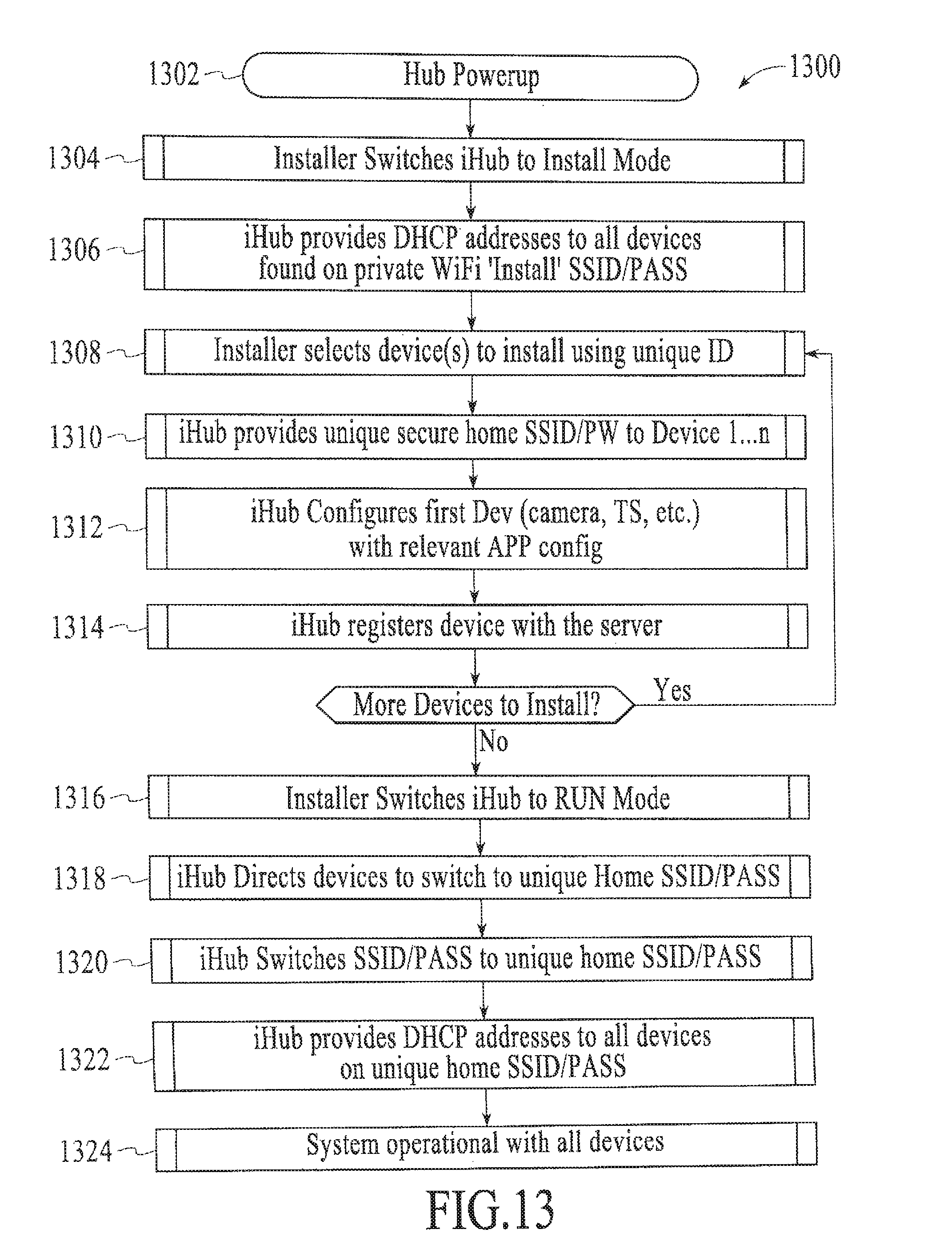
D00013
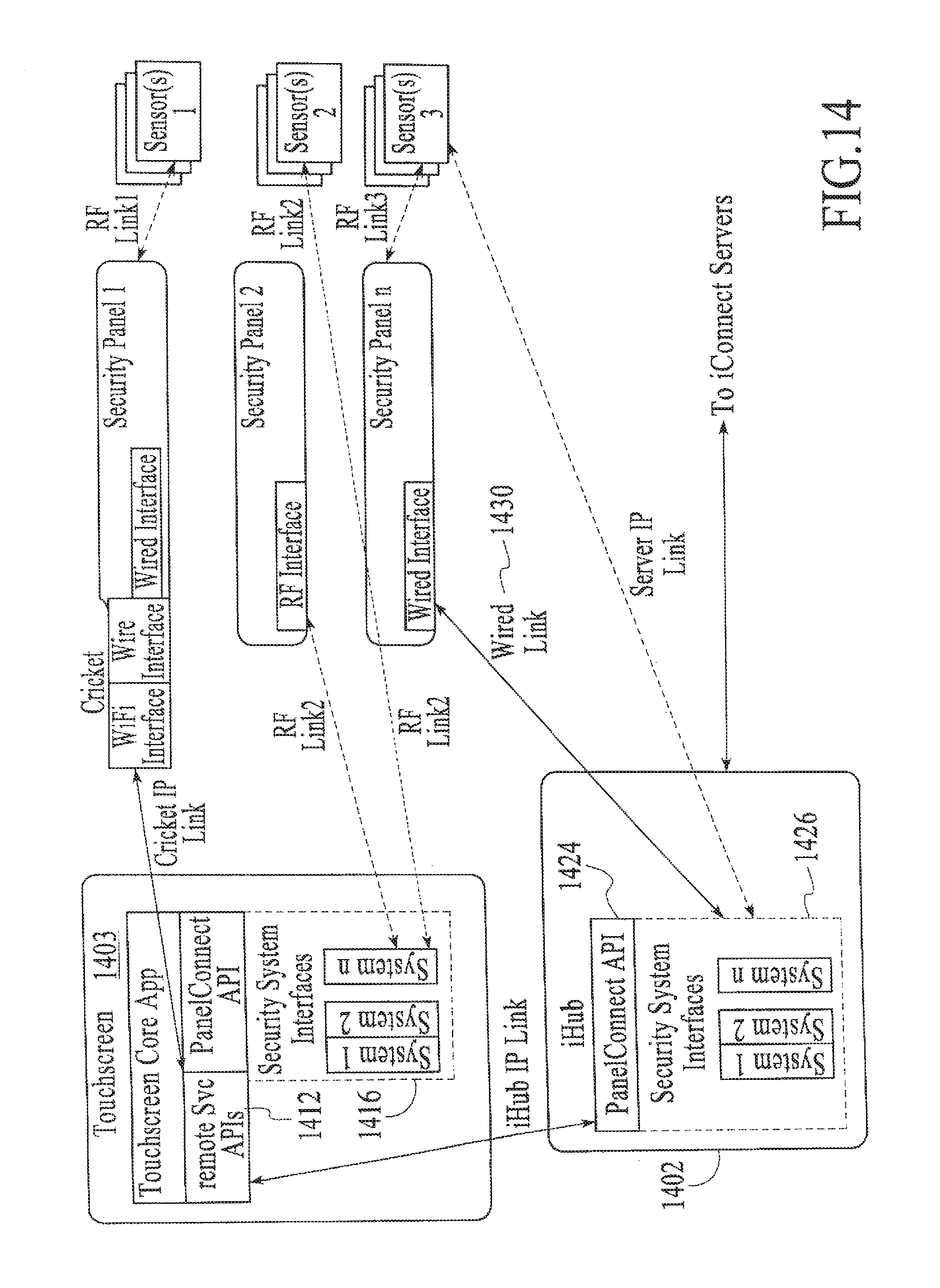
D00014
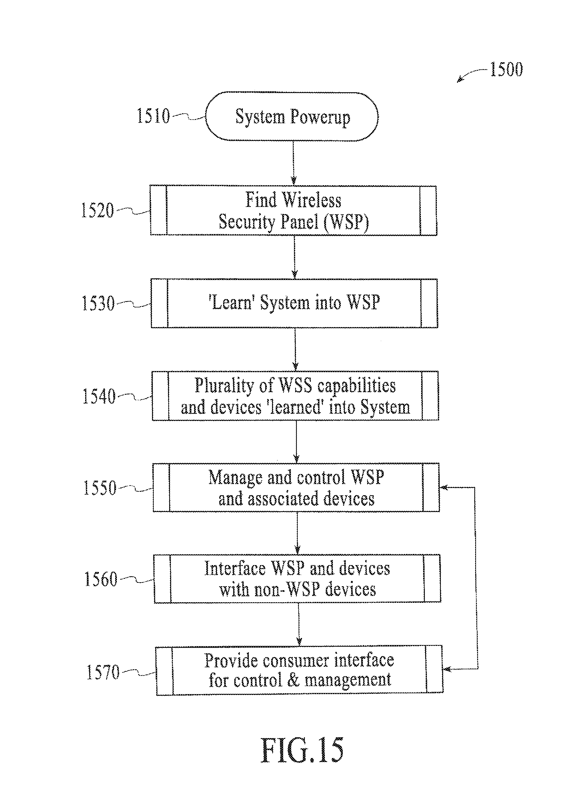
D00015
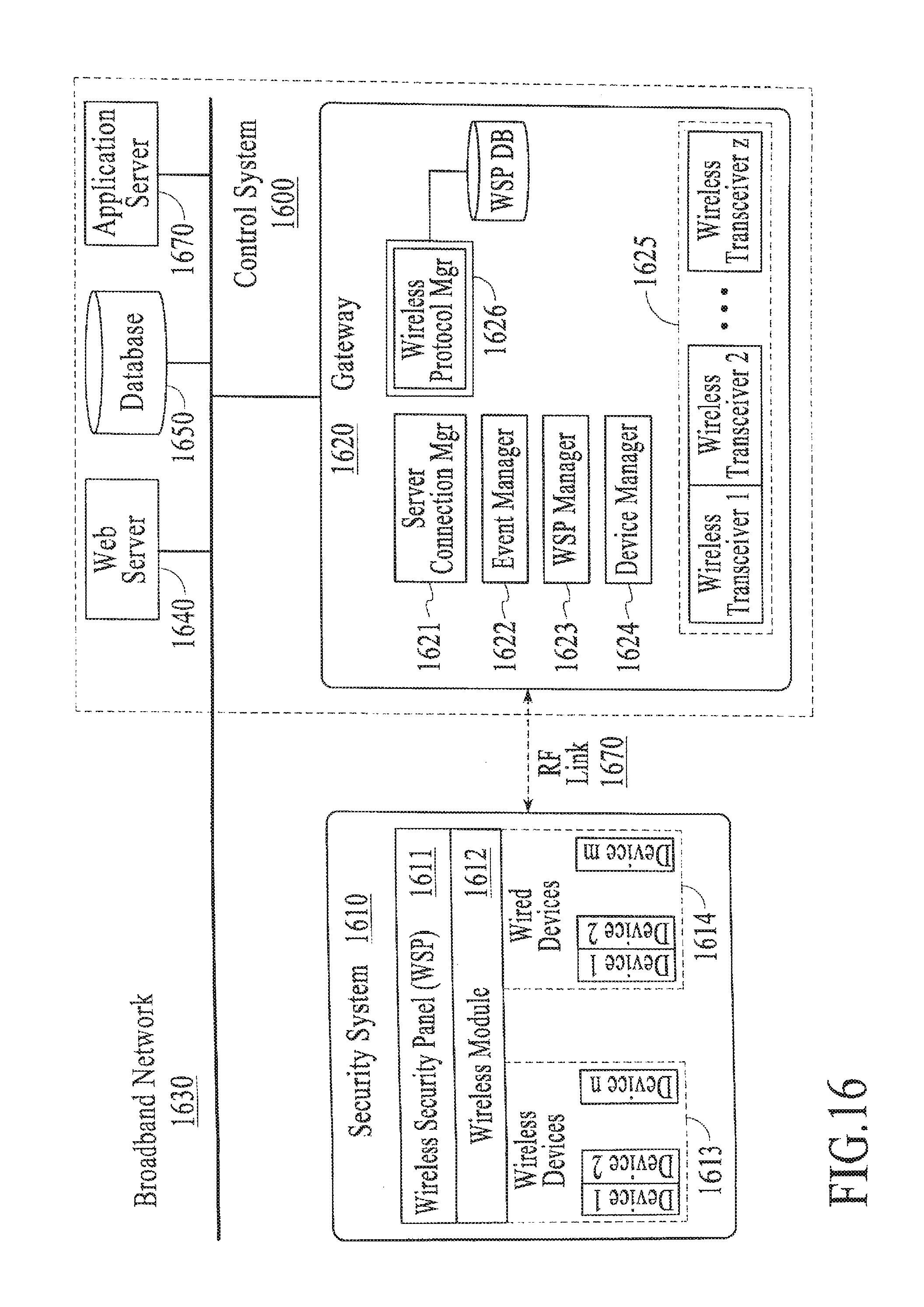
D00016

D00017
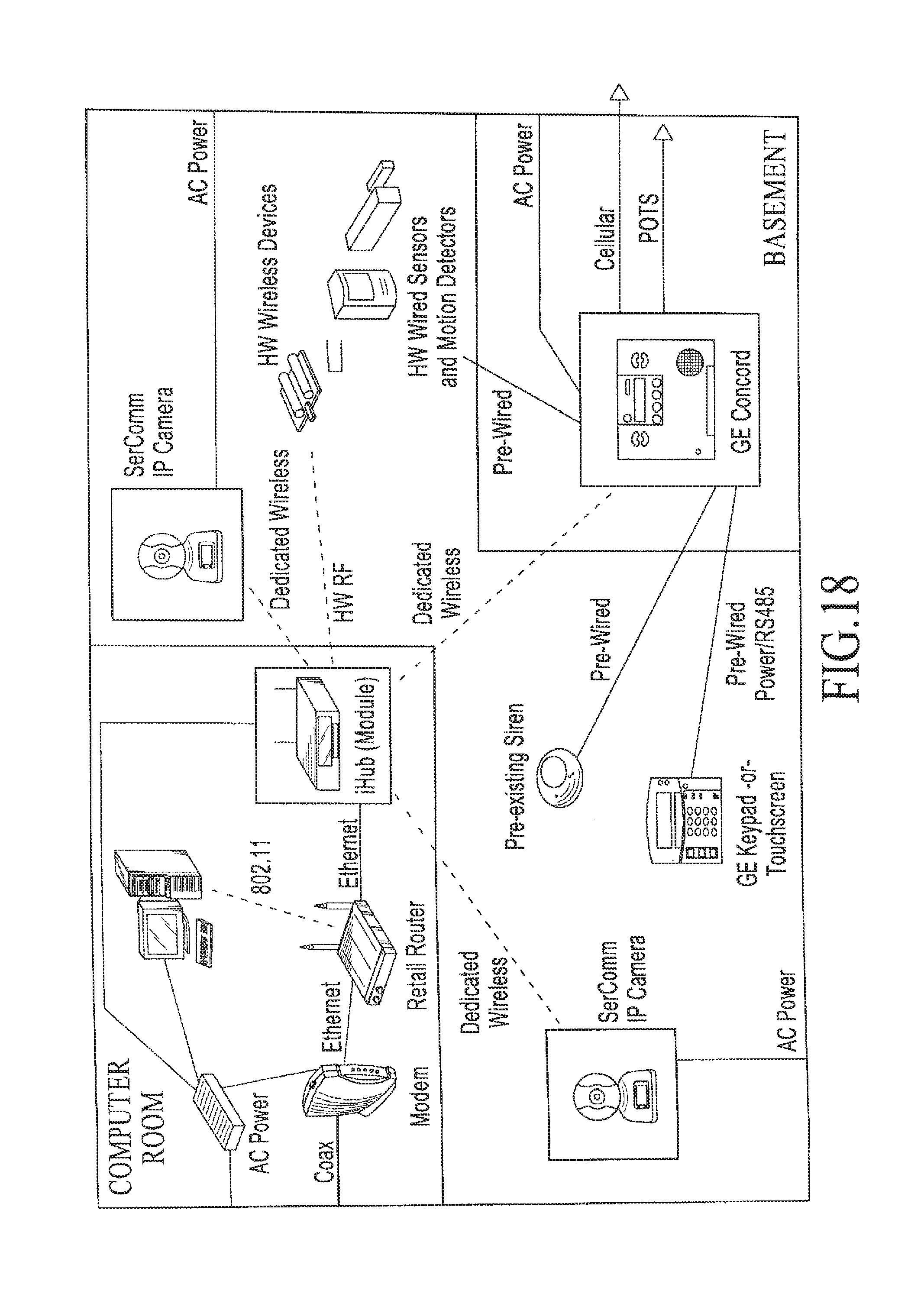
D00018
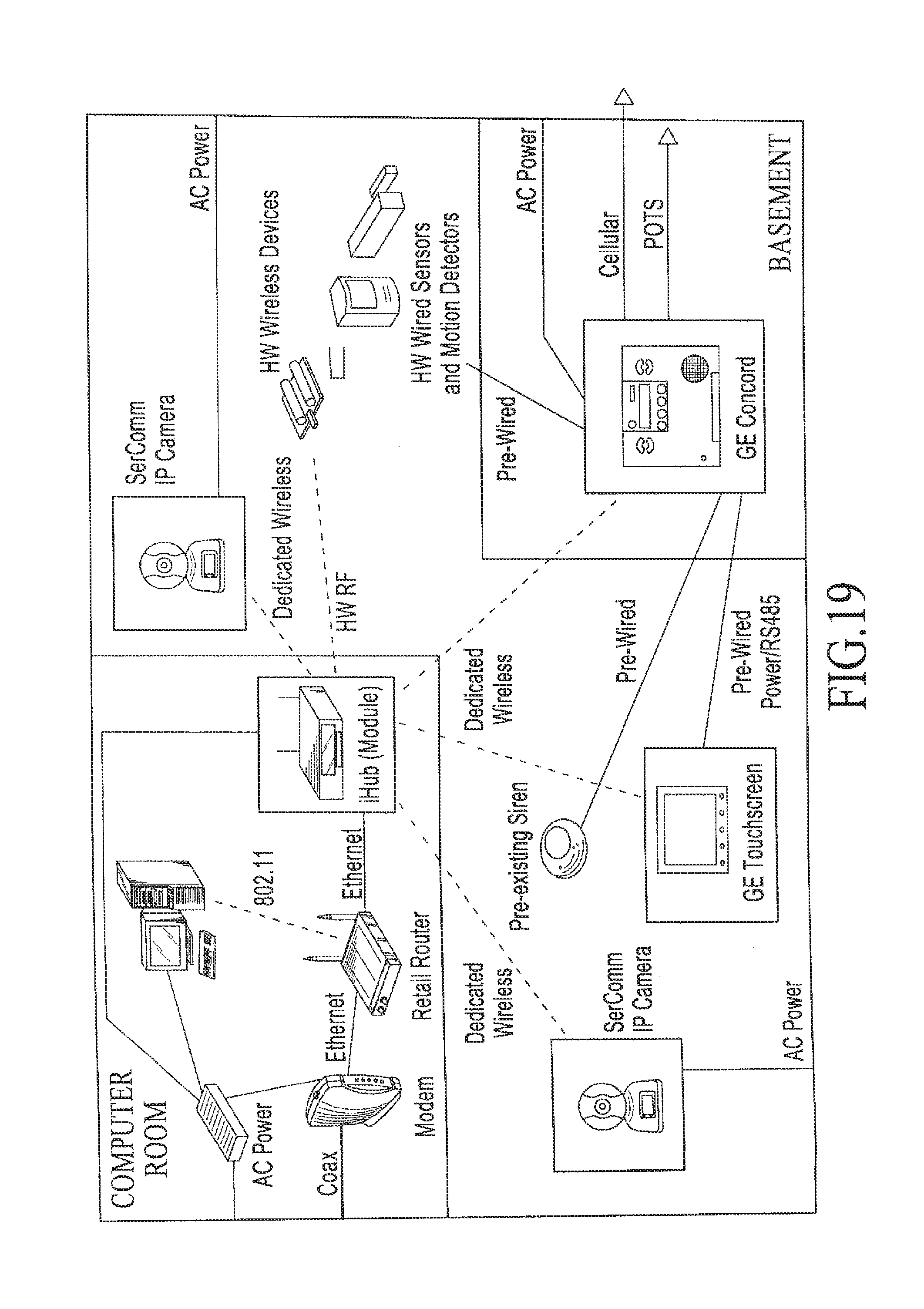
D00019
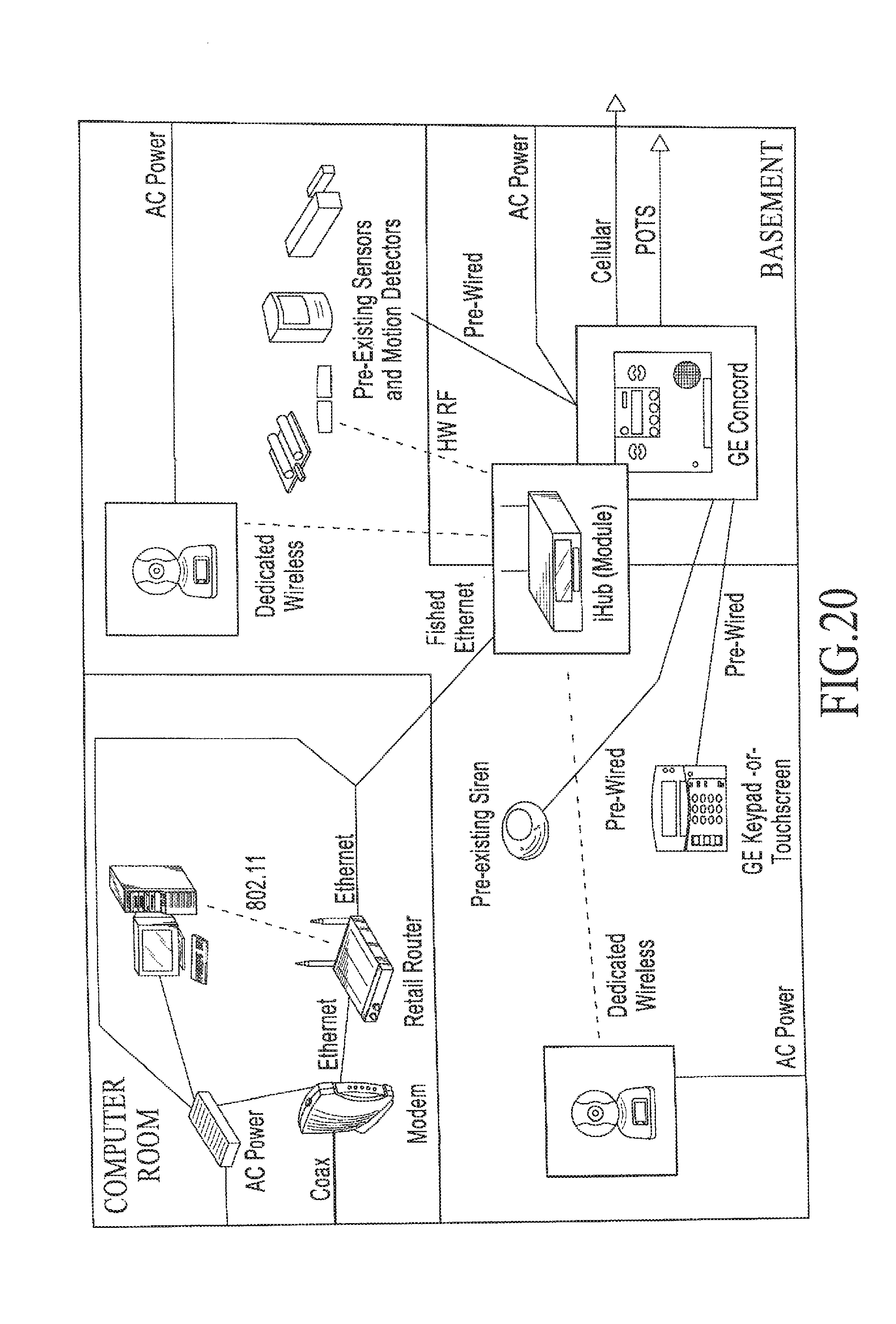
D00020
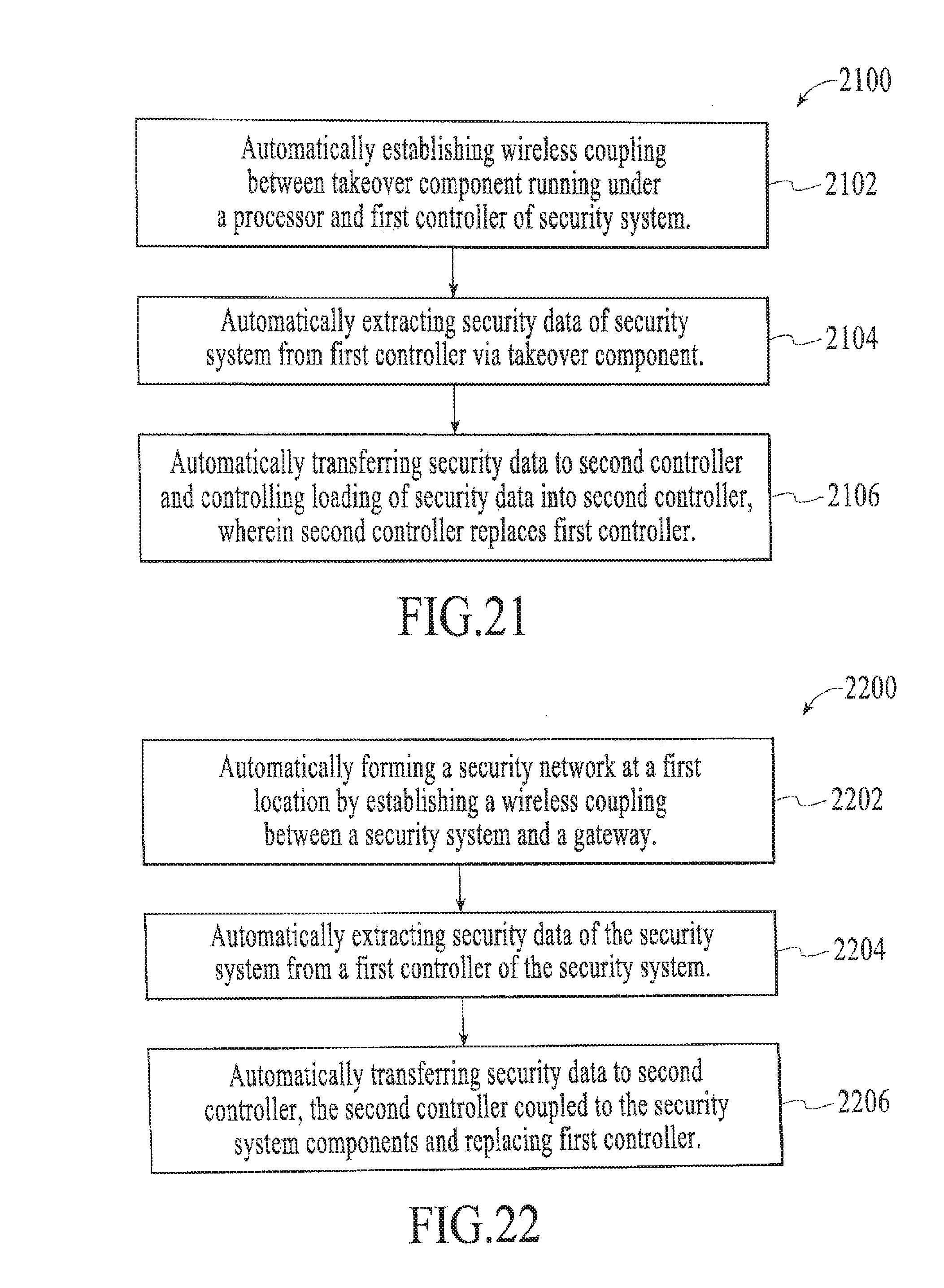
D00021
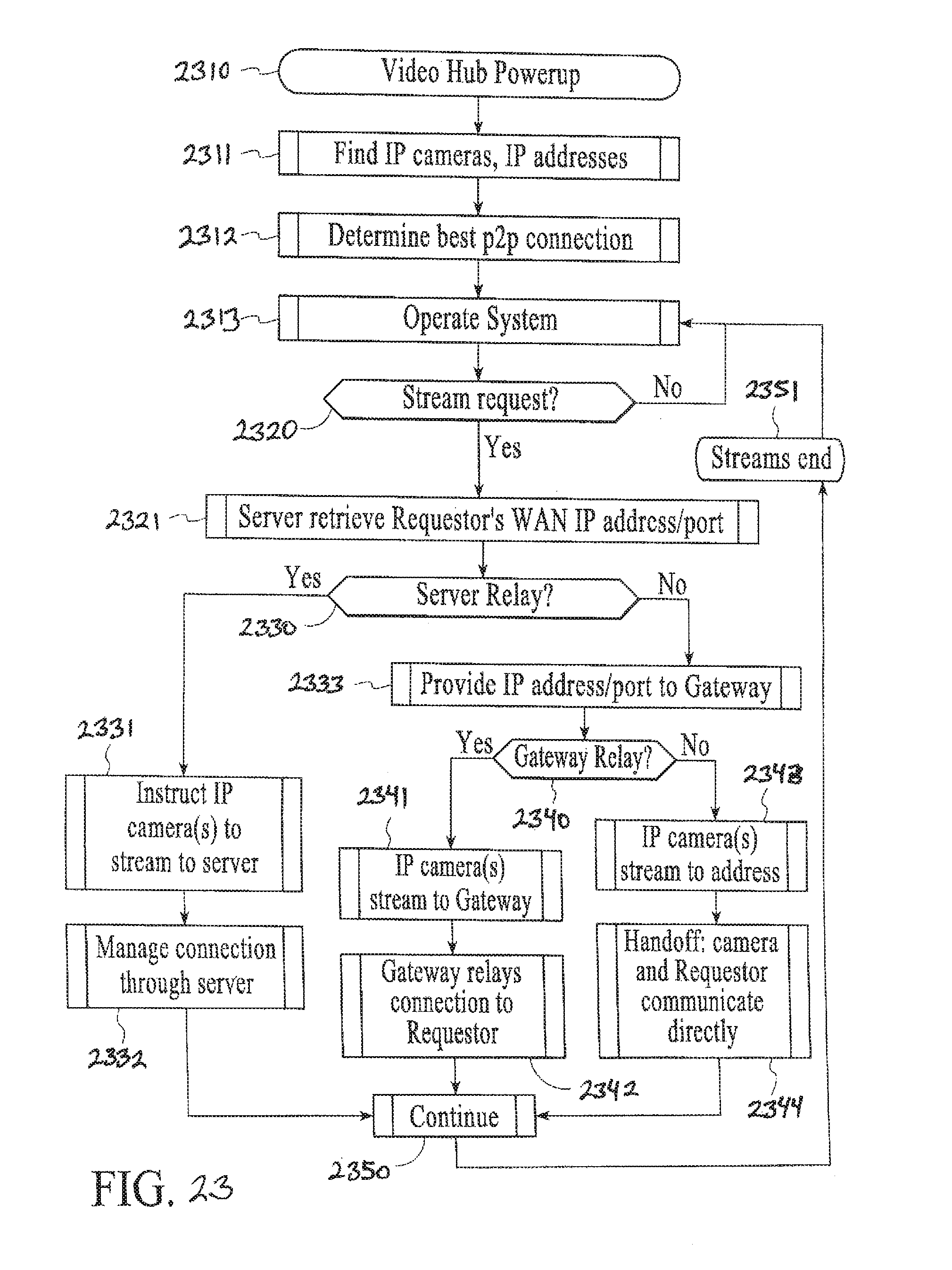
D00022

D00023
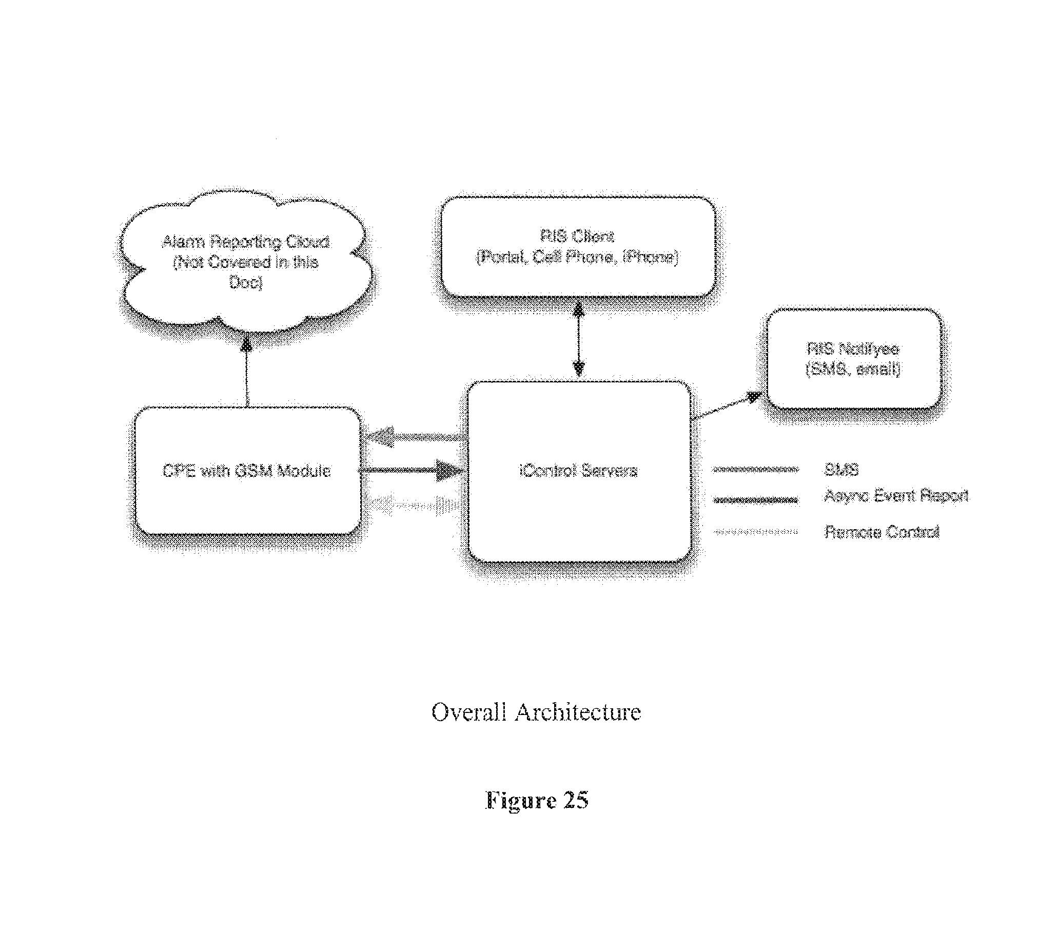
D00024
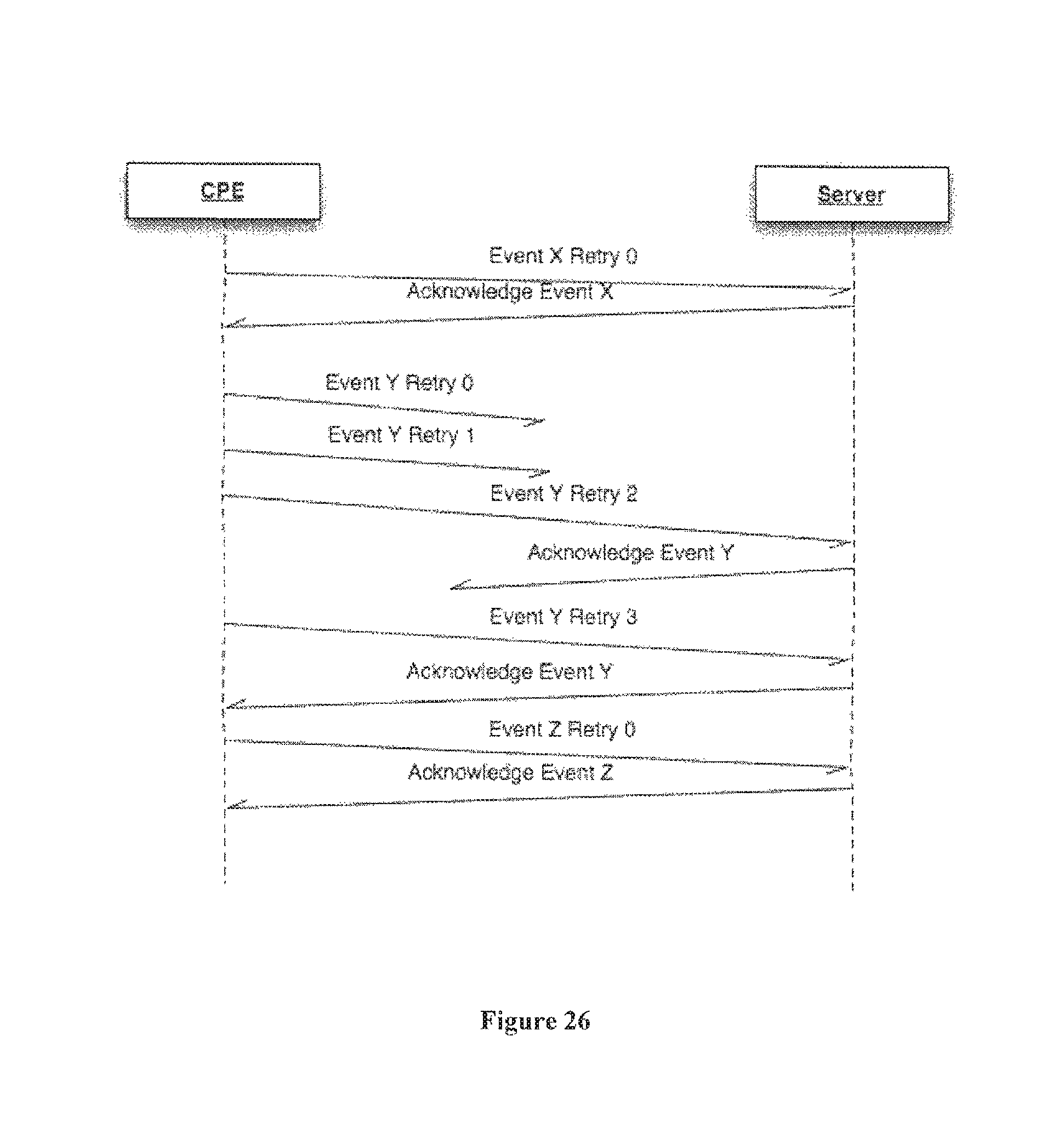
D00025
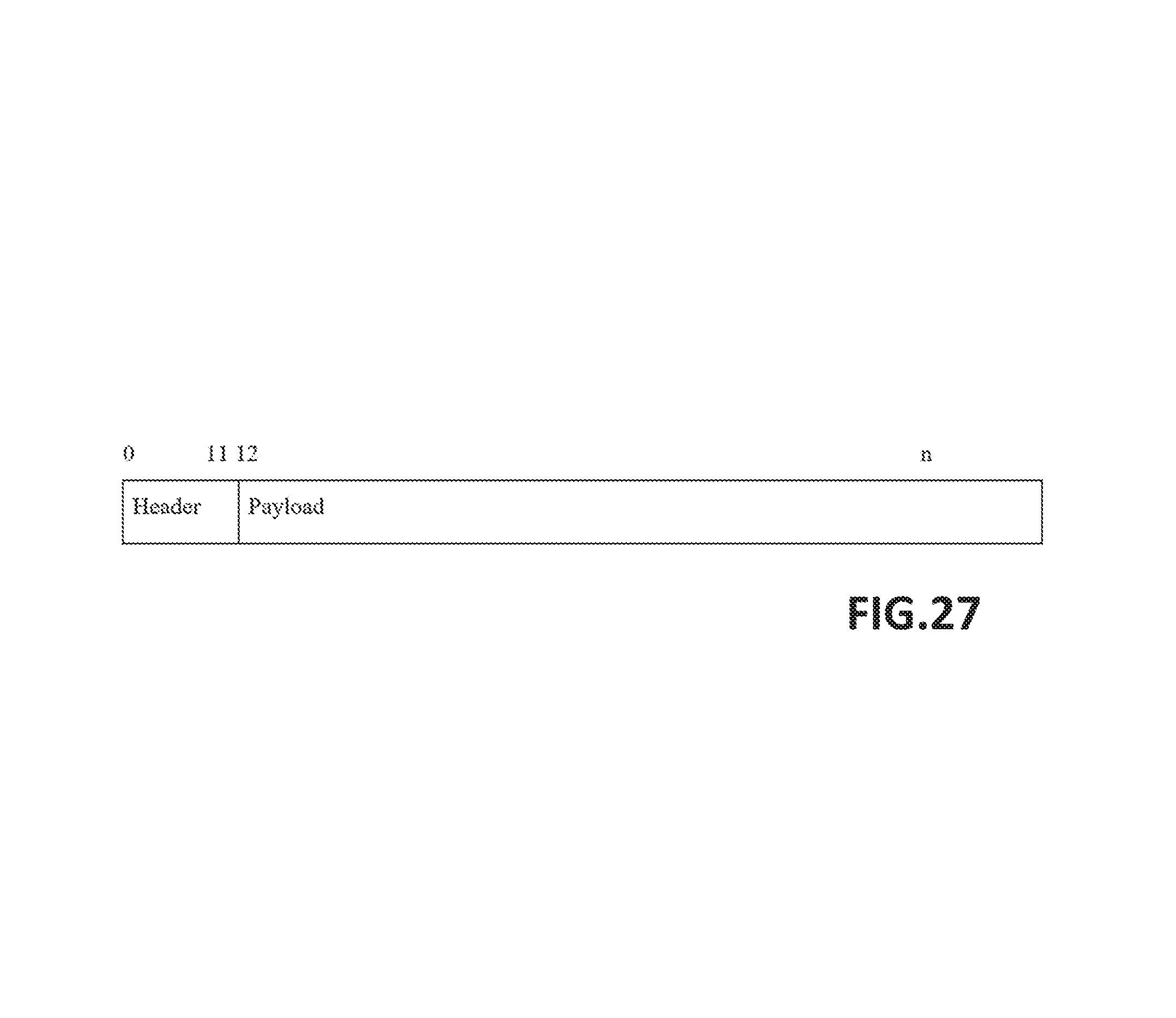
XML
uspto.report is an independent third-party trademark research tool that is not affiliated, endorsed, or sponsored by the United States Patent and Trademark Office (USPTO) or any other governmental organization. The information provided by uspto.report is based on publicly available data at the time of writing and is intended for informational purposes only.
While we strive to provide accurate and up-to-date information, we do not guarantee the accuracy, completeness, reliability, or suitability of the information displayed on this site. The use of this site is at your own risk. Any reliance you place on such information is therefore strictly at your own risk.
All official trademark data, including owner information, should be verified by visiting the official USPTO website at www.uspto.gov. This site is not intended to replace professional legal advice and should not be used as a substitute for consulting with a legal professional who is knowledgeable about trademark law.