Systems and methods for making and using mounts for receiving objects and coupling to surfaces
Carnevali A
U.S. patent number 10,378,690 [Application Number 15/650,732] was granted by the patent office on 2019-08-13 for systems and methods for making and using mounts for receiving objects and coupling to surfaces. This patent grant is currently assigned to NATIONAL PRODUCTS, INC.. The grantee listed for this patent is National Products, Inc.. Invention is credited to Jeffrey D. Carnevali.


View All Diagrams
| United States Patent | 10,378,690 |
| Carnevali | August 13, 2019 |
Systems and methods for making and using mounts for receiving objects and coupling to surfaces
Abstract
A mount for receiving a cylindrical element includes a retention assembly that retains the cylindrical element between the retention assembly and a base. The retention assembly includes arm segments extending from the base and retaining members disposed along at least one of the arm segments. The retaining members are separated from each other by a gap through which the cylindrical element is insertable. At least one of the arm segments or retaining members is resilient so that the gap is widened when that cylindrical element is pushed through the gap. The retaining members retain the cylindrical element between the retaining members and the base until force is applied to pull the cylindrical element back through the gap. A biasing member extends from, and is moveable relative to, the base to bias the cylindrical element against the retaining members while lacking sufficient force to push the cylindrical element through the gap.
| Inventors: | Carnevali; Jeffrey D. (Seattle, WA) | ||||||||||
|---|---|---|---|---|---|---|---|---|---|---|---|
| Applicant: |
|
||||||||||
| Assignee: | NATIONAL PRODUCTS, INC.
(Seattle, WA) |
||||||||||
| Family ID: | 64998731 | ||||||||||
| Appl. No.: | 15/650,732 | ||||||||||
| Filed: | July 14, 2017 |
Prior Publication Data
| Document Identifier | Publication Date | |
|---|---|---|
| US 20190017651 A1 | Jan 17, 2019 | |
| Current U.S. Class: | 1/1 |
| Current CPC Class: | F16M 11/2085 (20130101); F16M 11/425 (20130101); A47B 95/008 (20130101); F16M 11/2064 (20130101); F16M 11/2078 (20130101); F16M 11/14 (20130101); F16M 13/02 (20130101); F16M 2200/045 (20130101); F16M 2200/022 (20130101); F16M 2200/024 (20130101); F16M 2200/065 (20130101) |
| Current International Class: | F16M 11/14 (20060101); F16M 11/20 (20060101); F16M 13/02 (20060101); A47B 95/00 (20060101); F16M 11/42 (20060101) |
| Field of Search: | ;248/128,68.1,67.7,70,72,74.4 |
References Cited [Referenced By]
U.S. Patent Documents
| 180881 | August 1876 | Howson |
| 538534 | April 1895 | Neill |
| 596729 | January 1898 | White |
| 842007 | January 1907 | Parker |
| 855149 | May 1907 | Vaughn et al. |
| 890656 | June 1908 | Johnson |
| 892105 | June 1908 | White |
| 958052 | May 1910 | Williams |
| 1009913 | November 1911 | Maguire et al. |
| 1280013 | September 1918 | Goddard |
| 1359645 | November 1920 | Zink |
| 1455441 | May 1923 | Hodny |
| 1509068 | September 1924 | Herron |
| 1934223 | November 1933 | Booth |
| 2029089 | January 1936 | Weirauch |
| 2114767 | April 1938 | Hodny et al. |
| 2121317 | June 1938 | Cohen |
| D142057 | August 1945 | Baxter |
| 2560556 | July 1951 | Creedon |
| 2650788 | September 1953 | Hulstein |
| 2688504 | September 1954 | Parker |
| 2710609 | June 1955 | Giller |
| 2723823 | November 1955 | Polk |
| 2752173 | June 1956 | Krooss |
| 2859710 | November 1958 | Elsner |
| 2861501 | November 1958 | Strelakos |
| 3096061 | July 1963 | Bertell |
| 3252677 | May 1966 | Raymond |
| 3304038 | February 1967 | Guthrie |
| 3605637 | September 1971 | Prete, Jr. |
| 3652050 | March 1972 | Marrujo et al. |
| 3779502 | December 1973 | Marberg |
| 3843272 | October 1974 | Jorn |
| 4060241 | November 1977 | Hegel |
| 4060331 | November 1977 | Domer et al. |
| 4066231 | January 1978 | Bahner |
| 4066311 | January 1978 | Poulson |
| D247420 | March 1978 | Reynolds |
| 4085684 | April 1978 | McLennan et al. |
| 4183387 | January 1980 | Lenz |
| 4205486 | June 1980 | Guarnacci |
| 4222680 | September 1980 | Browning |
| 4225258 | September 1980 | Thompson |
| 4307864 | December 1981 | Benoit |
| 4461284 | July 1984 | Fackler |
| 4491435 | January 1985 | Meier |
| 4585197 | April 1986 | Liautaud et al. |
| 4611839 | September 1986 | Rung et al. |
| 4620813 | November 1986 | Lacher |
| 4641986 | February 1987 | Tsui et al. |
| 4677794 | July 1987 | Perron et al. |
| 4688843 | August 1987 | Hall |
| 4796508 | January 1989 | Hoshino |
| 4800795 | January 1989 | Yamashita |
| 4805784 | February 1989 | Solheim et al. |
| 4842308 | June 1989 | Spotts |
| 4872630 | October 1989 | Cooper |
| 4950099 | August 1990 | Roellin |
| 5071279 | December 1991 | Rustrom |
| 5092551 | March 1992 | Meier |
| 5109321 | April 1992 | Maglica et al. |
| 5118058 | June 1992 | Richter |
| 5241796 | September 1993 | Hellwig et al. |
| 5251859 | October 1993 | Cyrell et al. |
| 5259711 | November 1993 | Beck |
| 5270911 | December 1993 | Maglica et al. |
| 5284098 | February 1994 | Klapperich et al. |
| 5305700 | April 1994 | Strong et al. |
| 5419522 | May 1995 | Luecke et al. |
| 5441225 | August 1995 | Hall |
| 5564668 | October 1996 | Crowe, II |
| 5628597 | May 1997 | Chudoba et al. |
| 5727858 | March 1998 | Shapiro |
| 5823724 | October 1998 | Lee |
| 5845885 | December 1998 | Carnevali |
| 6173926 | January 2001 | Elvegaard |
| 6308642 | October 2001 | Branam et al. |
| 6561476 | May 2003 | Carnevali |
| 6581892 | June 2003 | Carnevali |
| 6588722 | July 2003 | Eguchi et al. |
| 6666420 | December 2003 | Carnevali |
| 6688568 | February 2004 | Moufflet |
| 6695183 | February 2004 | Hancock |
| 6789988 | September 2004 | Moradians |
| 6846140 | January 2005 | Anderson et al. |
| 6902089 | June 2005 | Carnevali |
| 6945414 | September 2005 | Stevens et al. |
| 7090181 | August 2006 | Biba et al. |
| 7100808 | September 2006 | Hancock |
| 7159998 | January 2007 | Moreland |
| D539639 | April 2007 | Nagle |
| 7277240 | October 2007 | Carnevali |
| 7320450 | January 2008 | Carnevali |
| D563781 | March 2008 | Carnevali |
| D564062 | March 2008 | Carnevali |
| 7337934 | March 2008 | Alling |
| 7401995 | July 2008 | Senakiewich, II |
| 7422184 | September 2008 | Carnevali |
| D588903 | March 2009 | Carnevali |
| D589327 | March 2009 | Carnevali |
| D590696 | April 2009 | Carnevali |
| 7523904 | April 2009 | Carnevali |
| 7551458 | June 2009 | Carnevali |
| 7556463 | July 2009 | Hall |
| 7571522 | August 2009 | Carnevali |
| 7607622 | October 2009 | Carnevali |
| 7682543 | March 2010 | Carnevali |
| 7731140 | June 2010 | Carnevali |
| 7774973 | August 2010 | Carnevali |
| D629080 | December 2010 | Dole et al. |
| 7849630 | December 2010 | Carnevali |
| 7850133 | December 2010 | Carnevali |
| 7854204 | December 2010 | Dacus |
| RE42060 | January 2011 | Carnevali |
| 7887018 | February 2011 | Carnevali |
| 7950701 | May 2011 | Dole et al. |
| 7954773 | June 2011 | Carnevali |
| 7975971 | July 2011 | Carnevali |
| 7980798 | July 2011 | Kuehn et al. |
| RE42581 | August 2011 | Carnevali |
| 7988106 | August 2011 | Carnevali |
| 8020828 | September 2011 | Carnevali |
| 8037904 | October 2011 | Carnevali |
| 8156681 | April 2012 | Carnevali |
| 8201788 | June 2012 | Carnevali |
| 8235340 | August 2012 | Carnevali |
| RE43806 | November 2012 | Carnevali |
| 8322955 | December 2012 | Arnesen et al. |
| 8408853 | April 2013 | Womack et al. |
| 8454178 | June 2013 | Carnevali |
| 8505861 | August 2013 | Carnevali |
| 8534519 | September 2013 | Hancock |
| 8590855 | November 2013 | Carnevali |
| 8651289 | February 2014 | Diaz, Jr. |
| 8776698 | July 2014 | Pherson |
| 8992238 | March 2015 | Chinn |
| 9056580 | June 2015 | Baldsiefen et al. |
| 9180925 | November 2015 | Carnevali |
| 9253970 | February 2016 | Carnevali |
| 9365150 | June 2016 | Baldsiefen et al. |
| 9379504 | June 2016 | Chinn |
| 9623787 | April 2017 | Sterling |
| 9671060 | June 2017 | Cifers |
| 9828073 | November 2017 | Cifers, III |
| 9944217 | April 2018 | Schroeder et al. |
| 9975466 | May 2018 | Hendren et al. |
| 9987993 | June 2018 | Thorimbert |
| 2003/0042282 | March 2003 | Gates |
| 2003/0185008 | October 2003 | Moreland |
| 2004/0178309 | September 2004 | Crowley et al. |
| 2005/0036848 | February 2005 | Cunningham et al. |
| 2005/0092876 | May 2005 | Carnevali |
| 2005/0132937 | June 2005 | Branam |
| 2006/0000957 | January 2006 | Carnevali |
| 2006/0102823 | May 2006 | Carnevali |
| 2008/0115344 | May 2008 | Carnevali |
| 2008/0296334 | December 2008 | Carnevali |
| 2009/0014584 | January 2009 | Ruddock et al. |
| 2009/0095206 | April 2009 | Dacus |
| 2009/0108151 | April 2009 | Carnevali |
| 2009/0108152 | April 2009 | Carnevali |
| 2009/0140112 | June 2009 | Carnevali |
| 2009/0241293 | October 2009 | Swerdlick |
| 2010/0282802 | November 2010 | Carnevali |
| 2010/0284199 | November 2010 | Carnevali |
| 2010/0288843 | November 2010 | Arnesen et al. |
| 2011/0097177 | April 2011 | Carnevali |
| 2012/0006948 | January 2012 | Hiss et al. |
| 2012/0181409 | July 2012 | Hayahara et al. |
| 2012/0217353 | August 2012 | Hennon |
| 2012/0318937 | December 2012 | Carnevali |
| 2013/0133158 | May 2013 | Tran |
| 2014/0003878 | January 2014 | Knox et al. |
| 2014/0034794 | February 2014 | Carnevali |
| 2014/0226315 | August 2014 | Nicieja et al. |
| 2014/0248103 | September 2014 | Baldsiefen et al. |
| 2015/0030386 | January 2015 | Carnevali |
| 2015/0275942 | October 2015 | Carnevali |
| 2016/0288691 | October 2016 | Aubrey et al. |
| 2017/0209318 | July 2017 | Schroeder et al. |
Other References
|
US. Appl. No. 15/612,764, filed Jun. 2, 2017. cited by applicant . U.S. Appl. No. 15/612,798, filed Jun. 2, 2017. cited by applicant . U.S. Appl. No. 15/627,102, filed Jun. 19, 2017. cited by applicant . U.S. Appl. No. 15/650,726, filed Jul. 14, 2017. cited by applicant . Yakattack.us, 7 pages of product description of GearTrac retrieved from web site at: www.yakattack.us/by-product-name/geartrac/. cited by applicant . Yakattack.us, 4 pages of product description of GTTL retrieved from web site at: www.yakattack.us/geartrac/gttl/. cited by applicant . Yakattack.us, 6 pages of product description of GTSL90 retrieved from web site at: www.yakattack.us/by-product-name/geartrac/gtsl90/. cited by applicant . Yakattack.us, 5 pages of product description of GT90 retrieved from web site at: www.yakattack.us/geartrac/gt90/. cited by applicant . Yakattack.us, 4 pages of product description of GT175 retrieved from web site at: www.yakattack.us/geartrac/gt175/. cited by applicant. |
Primary Examiner: Millner; Monica E
Attorney, Agent or Firm: Lowe Graham Jones PLLC Black; Bruce E.
Claims
What is claimed as new and desired to be protected by Letters Patent of the United States is:
1. A mount for receiving a cylindrical element, the mount comprising: a base; a retention assembly coupled to the base and configured and arranged to retain the cylindrical element between the retention assembly and the base, the retention assembly comprising a plurality of arm segments, each arm segment extending from the base, and at least two retaining members, each retaining member disposed at the distal end of at least one of the plurality of arm segments, wherein the retaining members are separated from each other by a gap through which the cylindrical element is insertable, wherein at least one of the arm segments or retaining members is resilient so that the gap is widened when that cylindrical element is pushed through the gap, wherein the retaining members retain the cylindrical element between the retaining members and the base until force is applied to pull the cylindrical element back through the gap; and a biasing member extending from, and moveable relative to, the base to engage the cylindrical element and bias the cylindrical element against the retaining members while lacking sufficient force to push the cylindrical element through the gap, wherein the biasing member comprises a movable element and at least one biasing element urging the movable element to move relative to the base.
2. The mount of claim 1, wherein the arm segments are resilient and the retaining members are rigid.
3. The mount of claim 1, wherein the retaining members are resilient and the arm segments are rigid.
4. The mount of claim 1, wherein the retaining members are resilient and the arm segments are resilient.
5. The mount of claim 1, wherein the retaining members are rotatable relative to the arm segments, the rotation of the retaining members facilitating insertion of the cylindrical element through the gap.
6. The mount of claim 1, wherein the retention assembly comprises at least one multi-arm assembly, the at least one multi-arm assembly comprising at least two of the arm segments coupled together into one of a U-shape or a C-shape.
7. The mount of claim 1, wherein the arm segments are each individually coupled to the base.
8. The mount of claim 1, wherein the at least one biasing element comprises a coiled spring.
9. A mount assembly, comprising: the mount of claim 1; and a retention element coupled to the base of the mount, the retention element configured and arranged to couple the mount to a mounting track.
10. A mounting system, comprising: the mount assembly of claim 9, and a mounting track configured and arranged for attaching to a surface and to receive the retention element of the mount assembly.
11. A method for mounting a cylindrical element to a mount, the method comprising: providing the mount of claim 1; and inserting the cylindrical element through the gap between the retaining members of the mount and against the biasing member of the mount.
12. The mount of claim 5, wherein each of the retaining members is configured to rotate 360 degrees about an axis.
13. The mount of claim 1, wherein at least one the biasing element is configured to push the movable element to extend out of the base.
14. The mount of claim 13, wherein the movable element is configured to at least partially retract into the base upon application of a force countering the at least one biasing element.
15. The mount of claim 1, wherein the retaining members extend distally beyond the arm segments.
16. The mount of claim 1, wherein the movable element of the biasing member is unattached to the base so that the movable element is freely movable relative to the base.
17. The mount of claim 1, wherein the retaining elements are spherical.
18. The mount of claim 1, wherein the retaining elements are cylindrical.
19. The mount of claim 1, wherein the retaining elements are configured to engage the cylindrical element and push the cylindrical element against the movable element of the biasing member.
20. The mount of claim 8, wherein the coiled spring is configured to be compressed when the cylindrical element is retained between the retention assembly and the base.
Description
FIELD
The present invention is directed to mounts to receive objects and to couple to surfaces. The present invention is also directed to mounts configured and arranged to receive objects and couple to mounting tracks.
BACKGROUND
Providing mounts for holding, retaining, or securing objects has proven beneficial for many different uses. Some mountable-objects, such as electronic devices (e.g., phones, laptops, tablets, visual-enhancement devices, positioning devices, or the like), or manual-activity-based objects (e.g., cylindrical elements, oars, or the like) are increasingly used in situations where mounting the object to a surface increases the convenience of using the object. For example, mounts may eliminate the need to hold an object, or prop the device up, in order to use the object, thereby allowing a user to use the object more efficiently, or while simultaneously engaging in other activities which may benefit from the use of both hands without the encumberment of holding or propping-up the object. In some instances, mounting an object may increase user safety by enabling use of the object, without the distraction of holding the object.
Track systems enable an object to be held, retained, or secured, while also enabling limited movement of the object along a fixed path, or track. Attaching track systems to a surface provides a way to mount an object to the surface while also allowing flexibility of positioning of the object along portions of the surface along which the track system extends.
BRIEF SUMMARY
In one embodiment, a mount for receiving a cylindrical element includes a retention assembly coupled to a base and configured to retain the cylindrical element between the retention assembly and the base. The retention assembly includes arm segments extending from the base and at least two retaining members disposed at the distal end of at least one of the arm segments. The retaining members are separated from each other by a gap through which the cylindrical element is insertable. At least one of the arm segments or retaining members is resilient so that the gap is widened when that cylindrical element is pushed through the gap. The retaining members retain the cylindrical element between the retaining members and the base until force is applied to pull the cylindrical element back through the gap. A biasing member extends from, and is moveable relative to, the base to bias the cylindrical element against the retaining members while lacking sufficient force to push the cylindrical element through the gap.
In at least some embodiments, the arm segments are resilient and the retaining members are rigid. In at least some embodiments, the retaining members are resilient and the arm segments are rigid. In at least some embodiments, the retaining members are resilient and the arm segments are resilient.
In at least some embodiments, the retaining members are rotatable relative to the arm segments, the rotation of the retaining members facilitating insertion of the cylindrical element through the gap. In at least some embodiments, the retention assembly includes at least one multi-arm assembly, the at least one multi-arm assembly including at least two of the arm segments coupled together into one of a U-shape or a C-shape. In at least some embodiments, the arm segments are each individually coupled to the base. In at least some embodiments, the biasing member includes a movable element and a biasing element urging the movable element to move relative to the base. In at least some embodiments, the biasing element includes a coiled spring.
In another embodiment, a mount assembly includes the mount described above; and a retention element coupled to the base of the mount, the retention element configured to couple the mount to a mounting track.
In yet another embodiment, a mounting system includes the mount assembly described above, and a mounting track configured for attaching to a surface and to receive the retention element of the mount assembly.
In still yet another embodiment, a method for mounting a cylindrical element to a mount includes providing the mount described above; and inserting the cylindrical element through the gap between the retaining members of the mount and against the biasing member of the mount.
In another embodiment, an articulating mount assembly includes a base comprising a socket defining a first axis of rotation and a multi-axis coupling assembly coupled to the base. The multi-axis coupling assembly includes a spline insertable into the socket. A hub is coupled to the spline and configured to rotate about the base along the first axis of rotation. The hub is configured to rotatably couple with an articulating arm assembly so that the articulating arm assembly is rotatable relative to the hub along a second axis of rotation different from to the first axis of rotation. A slip disc washer is disposed between the spline and the hub. The slip disc washer is configured to control rotation of the hub about the first axis of rotation by increasing resistance to rotation while still permitting full rotation of the hub about the first axis of rotation.
In at least some embodiments, at least one retention element is configured to couple the base to a mounting track. In at least some embodiments, the base and socket are formed as a single-piece structure. In at least some embodiments, the second axis of rotation is orthogonal to the first axis of rotation.
In at least some embodiments, the articulating arm assembly is coupled to the hub along the second axis of rotation. The articulating arm assembly includes a first arm having a proximal end and an opposing distal end. The proximal end of the first arm is coupled to the hub and configured to rotate about the second axis of rotation. A second arm has a proximal end and an opposing distal end. The proximal end of the second arm is rotatably coupled to the distal end of the first arm along a third axis of rotation. The distal end of the second arm is configured to receive a mount.
In yet another embodiment, an articulating mount system includes the articulating mount assembly described above and a mount coupleable to the distal end of the second member of the articulating mount assembly. The mount is configured to to couple an object to the articulating mount assembly. In at least some embodiments, the mount is a ball mount.
In still yet other embodiments, a method of mounting an object to a mounting track includes providing the articulating mount system described above; coupling the base of the articulating mount system to a mounting track; and mounting the object to the mount disposed along the articulating mount assembly.
BRIEF DESCRIPTION OF THE DRAWINGS
Non-limiting and non-exhaustive embodiments of the present invention are described with reference to the following drawings. In the drawings, like reference numerals refer to like parts throughout the various figures unless otherwise specified.
For a better understanding of the present invention, reference will be made to the following Detailed Description, which is to be read in association with the accompanying drawings, wherein:
FIG. 1 is a schematic perspective view of one embodiment of a cylindrical element suitable for being received by a mount positioned along a mounting track, according to the invention;
FIG. 2A is a schematic perspective view of one embodiment of the cylindrical element of FIG. 1 received by the mount of FIG. 1 and positioned along the mounting track of FIG. 1, according to the invention;
FIG. 2B is a schematic close-up perspective view of one embodiment of the cylindrical element of FIG. 2A received by the mount of FIG. 2A and positioned along the mounting track of FIG. 2A, according to the invention;
FIG. 3A is a schematic side view of one embodiment of the cylindrical element of FIG. 1 positioned over a pair of retaining members and arm segments of a retention assembly of the mount of FIG. 1, the retention assembly in a relaxed configuration with the pair of retaining members separated from each other by a gap through which the cylindrical element is insertable, according to the invention;
FIG. 3B is a schematic side view of one embodiment of the cylindrical element of FIG. 3A partially positioned between the pair of retaining members of FIG. 3A, the cylindrical element causing the gap between the retaining members to extend, according to the invention;
FIG. 3C is a schematic side view of one embodiment of the cylindrical element of FIG. 3A fully positioned between the pair of retaining members of FIG. 3A and over a biasing member, the gap between the pair of retaining members extended to accommodate an entire lateral dimension of the cylindrical element, according to the invention;
FIG. 3D is a schematic side view of one embodiment of the cylindrical element of FIG. 3A retained by the mount of FIG. 3A with the cylindrical element physically contacted by the retaining members of the mount of FIG. 3A and the biasing member, according to the invention;
FIG. 4 is a schematic side view of another embodiment of a cylindrical element retained by the mount of FIG. 3A with the cylindrical element physically contacted by the pair of retaining members and the biasing member of the mount of FIG. 3A, according to the invention;
FIG. 5A is a schematic cross-sectional view of one embodiment of a cylindrical element positioned over the retention assembly and the biasing member of the mount of FIG. 1, the retention assembly and the biasing member each in a relaxed configuration, according to the invention;
FIG. 5B is a schematic cross-sectional view of one embodiment of the cylindrical element of FIG. 5A positioned in the mount with the retention assembly and the biasing member of the mount of FIG. 5A each physically contacting the cylindrical element, the retention assembly and the biasing member each in a stressed configuration and exerting forces against each other to retain the cylindrical element, according to the invention;
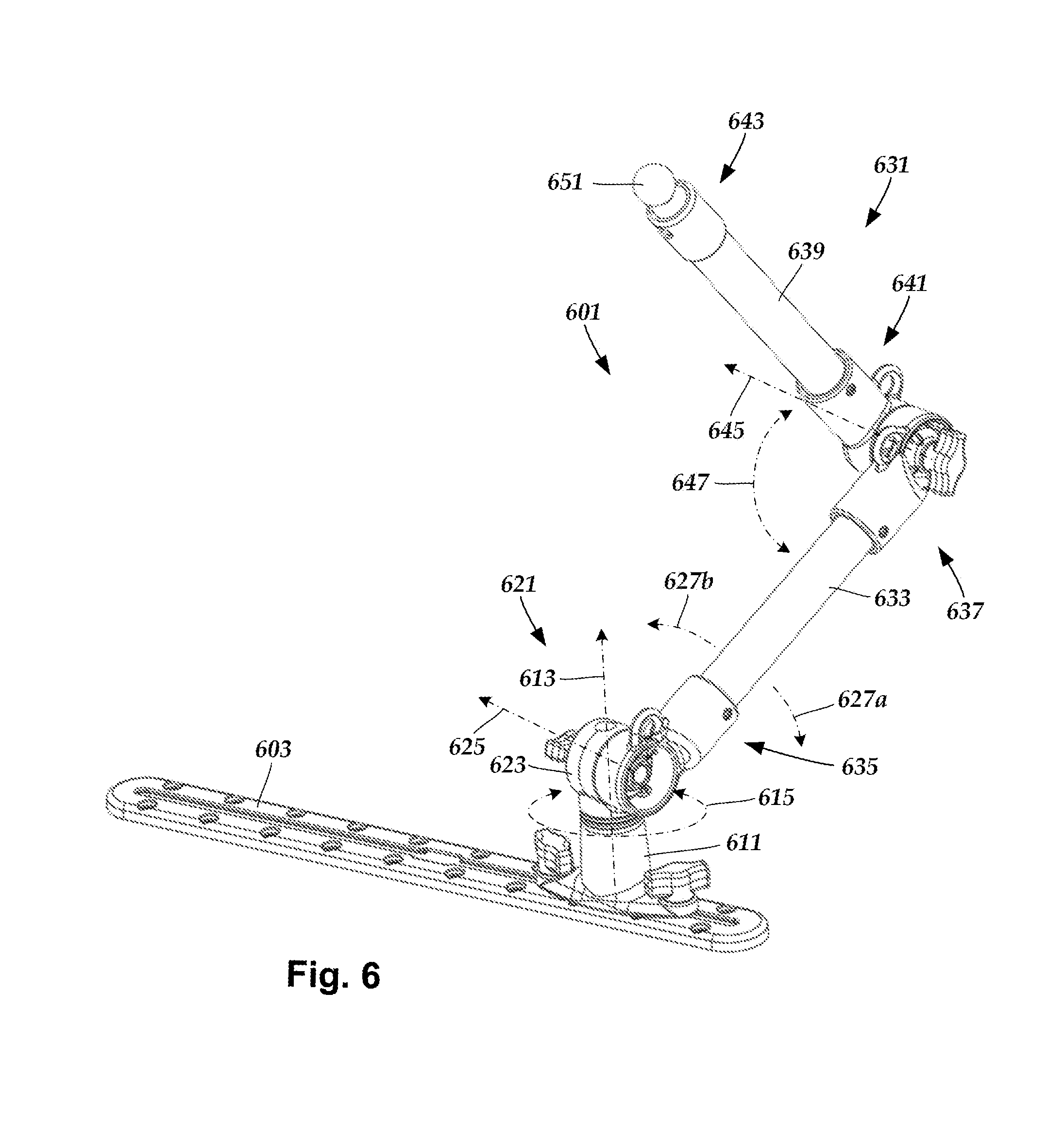
FIG. 6 is a schematic perspective view of one embodiment of an articulating mount assembly positioned along a mounting track, according to the invention;
FIG. 7 is a schematic perspective view of one embodiment of a portion of the articulating mount assembly of FIG. 6 disposed over the mounting track of FIG. 6, according to the invention; and
FIG. 8 is a schematic close-up perspective view of one embodiment of a portion of the articulating mount assembly of FIG. 6 disposed over the mounting track of FIG. 6, according to the invention.
DETAILED DESCRIPTION
The present invention is directed to mounts to receive objects and to couple to surfaces. The present invention is also directed to mounts configured and arranged to receive objects and couple to mounting tracks.
Mounts can be used for mounting objects to surfaces. In some instances, it may be advantageous to mount objects to surfaces by mounting the mounts to mounting tracks that, in turn, are attached to surfaces. Such an arrangement provides flexibility of location of the mounted object, as the mount is typically moveable, and retainable at multiple locations, along a fixed path defined by the mounting track.
A mounting track includes a continuous track formed along at least one track section along which a mount assembly, which includes a mount, can move. The continuous track retains the mount assembly to restrict movement of the mount to positions along the continuous track.
The mounting track can, optionally, be attached to a surface (e.g., a vehicle surface, a dock, a countertop, a railing, a gunwale, a cabinet, a table, a floor, a wall, a ceiling, a ledge, a handle, or the like). The mounting track can be configured to the size and shape of the surface to which the mounting track is attached. Examples of mounting tracks suitable for receiving mounts are found in, for example, U.S. patent application Ser. Nos. 15/612,764; 15/612,798; and Ser. No. 15/627,102, all of which are incorporated by reference.
Turning to FIGS. 1-5B, in some embodiments a mount is configured to receive a cylindrical element. FIG. 1 shows, in perspective view, one embodiment of a cylindrical element 101 suitable for being received by a mount 111 suitable for mounting to a surface. In the illustrated embodiment, the mount 111 is shown coupled to a mounting track 103 that is configured for attaching to a surface.
In some embodiments, the cylindrical element is entirely cylindrical (e.g., a tube, pipe, rod, or the like). In other embodiments, the cylindrical element is an elongated cylindrical portion of a larger object that includes one or more non-cylindrical portions. For example, the cylindrical element may be an oar, a fishing pole, or a handle of a tool, such as a hammer, shovel, screwdriver, or the like.
In some embodiments, the cylindrical element has a transverse profile that is circular, oblong, oval, capsule-shaped, or the like. In other embodiments, the cylindrical element has a transverse profile that is multi-sided. For example, the transverse profile of the cylindrical element may have three, four, five, six, seven, eight, nine, ten, eleven, twelve, or more sides.
FIG. 2A shows, in perspective view, the cylindrical element 101 received by the mount 111 and positioned along the mounting track 103. FIG. 2B shows a close-up view of the mount 111 positioned along the mounting track 103. The mount 111 is coupled to the mounting track 103 via a retention element (not shown in FIGS. 2A-2B), which is discussed in more detail below, with reference to FIGS. 5A-5B.
The mount 111 includes a retention assembly 115 coupled to a base 121. The retention assembly 115 is configured to guide and receive the cylindrical element 101 using multiple retaining members 125a, 125b disposed along distal ends of multiple arm segments 131a-d extending from the base 121. The retaining members 125a, 125b are configured to guide the cylindrical element 101 through a gap between the retaining members and push the cylindrical element against a biasing member extending from, and moveable relative to, the base to bias the cylindrical element against the retaining members while lacking sufficient force to push the cylindrical element through the gap.
The mount 111 can include any suitable number of arm segments extending from the base including, for example, two, three, four, five, six, seven, eight, or more arm segments. In FIGS. 2A-2B (and in other figures) four arm segments are shown. In some embodiments, at least some of the arm segments are physically separated from each of the remaining arm segments. In other embodiments, and as shown in the illustrated embodiments, two or more arm segments are connected together into multi-arm assemblies, such as multi-arm assemblies 133a, 133b. In at least some embodiments, the multi-arm assemblies are U-shaped, or C-shaped. In at least some embodiments, each multi-arm assembly 133a, 133b couples to multiple retaining members.
The mount 111 can include any suitable number of retaining members including, for example, two, three, four, five, six, seven, eight, or more retaining members. In FIGS. 2A-2B (and in other figures) two retaining members 125a, 125b are shown. In the illustrated embodiment, the retaining members are spherical. Other shapes, both geometric and non-geometric, are possible including, for example, oval, capsule-shaped, cylindrical, or the like. In at least some embodiments, at least one retaining member is rotatable. It may be advantageous for at least one of the retaining members to be rotatable to facilitate guidance of a cylindrical element between the arm segments.
The retaining members can be coupled to any suitable number of arm segments including, for example, one, two, three, four, five, six, seven, eight, or more arm segments. In the illustrated embodiment, each retaining member is coupled to two arm segments.
FIGS. 3A-3D show, in side view, one embodiment of the cylindrical element being received and retained by the mount 111. FIG. 3A shows the cylindrical element 101 positioned over the retention assembly 115 of the mount 111. The cylindrical element 101 is also disposed over a biasing member 137 disposed along the base 121.
As shown in FIG. 3A, the retaining members 125a, 125b of the retention assembly 115 are separated from one another by a gap having a first distance 141 when the retention assembly is in a relaxed configuration. As also shown in FIG. 3A, the cylindrical element includes at least one lateral dimension (shown in FIG. 3A as two-headed directional arrow 145) that is larger than the gap 141. Note that the lateral dimension is any dimension perpendicular to the long axis of the cylindrical element.
When the cylindrical element 101 passes between the guided elements 125a, 125b, the cylindrical element 101 extends the gap between the retaining members 125a, 125b, thereby exerting forces 151a, 151b that oppose the biasing of the retention assembly 115. When the cylindrical element 101 is moved in a direction 155 toward the biasing member 137, once the cylindrical element passes the beyond the gap 141 the retention assembly 115 pushes the cylindrical element against the biasing member 137.
FIG. 3B shows the cylindrical element 101 partially positioned between the retaining members 125a, 125b. The cylindrical element 101 causes the gap 141 to extend and the retention assembly 115 transitions to a strained configuration. FIG. 3C shows the cylindrical element 101 fully positioned between the retaining members 125a, 125b. The gap 141 between the retaining members 125a, 125b is further extended to accommodate the entire lateral dimension 145 of the cylindrical element 101.
As the cylindrical element 101 continues in the direction 155 from the position shown in FIG. 3C, the retention assembly 115 begins to counteract the opposing forces 151a, 151b exerted by the cylindrical element 101. As a result, the retention assembly pushes the cylindrical element 101 against the biasing member 137, causing it to move downward, as shown by directional arrow 165. The biasing of the biasing member 137 counteracts the downward force applied by the biasing of the retention assembly 115 with an upward (with respect to the base) force sufficient to retain the cylindrical element 101 without pushing the cylindrical element back through the gap.
FIG. 3D shows the cylindrical element 101 retained by the mount 111. The biasing of the retention assembly exerts inward forces 169a, 169b against the cylindrical element 101. The inward forces 169a, 169b also push the cylindrical element against the biasing member 137, as shown by directional arrow 155. At the same time, the bias of the biasing member 137 exerts a counteracting force, as shown by directional arrow 171, that pushes the cylindrical element 101 against the retaining member 125a, 125b. Collectively, the retention assembly and the biasing member retain the cylindrical element 101.
At least one of the arm segments or the two retaining members is resilient so that the gap is extended when that cylindrical element is pushed through the gap. The resiliency of the retention assembly can be generated by the arm segments, the retaining members, or a combination of both the arm segments and the retaining members. In at least some embodiments, at least one of the retaining members is resilient (e.g., compressible). In other embodiments, at least one of the retaining members is rigid. In at least some embodiments, at least one of the arm segments is resilient (e.g., flexible). In other embodiments, at least one of the arm segments is rigid.
The biasing of the biasing member can be generated in any suitable manner. In at least some embodiments, the biasing member is biased from at least one biasing element. The at least one biasing element can, for example, be implemented as at least one spring, such as at least one coiled spring. In at least some embodiments, the at least one biasing member extends from, and is moveable relative to, the base to bias the cylindrical element against the retaining members while lacking sufficient force to push the cylindrical element through the gap.
The mount can be used with cylindrical elements having different lateral dimensions and transverse shapes. FIG. 4 shows, in side view, of another embodiment of a cylindrical element 401 retained by the retention assembly 115 and the biasing member 137 of the mount 111. The cylindrical element 401 is physically contacted by the retaining members 125a, 125b and the biasing member 137. The cylindrical element 401 has a largest lateral dimension that is larger than the largest lateral dimension of the cylindrical element 101 of FIGS. 1-3D, yet the cylindrical element is still able to fit between the arm segments 131a, 131b and be retained by the mount 111. The cylindrical element 401 also has a different transverse cross-sectional shape than the cylindrical element 101. The cylindrical element 401 has a round transverse (lateral) shape, whereas the cylindrical element 101 has a dodecahedral transverse (lateral) shape.
FIG. 5A shows, in cross-sectional view, one embodiment of a cylindrical element 501 positioned over a mount assembly 573 coupled to the mounting track 103. The mount assembly 573 includes the mount 111 of FIGS. 1-4 and a retention element 575 coupleable to the mount 111. In FIGS. 5A-5B, the retention element 575 includes an elongated member attached to a flange. The elongated member is coupled to the mount 111, and the flange is coupled to the mounting track 103. The cylindrical element 401 is positioned over the retention assembly 115 of the mount 111.
The cylindrical element 501 is also disposed over the biasing member 137 and the base 121. As shown in FIG. 5A, the retention assembly 115 is in a relaxed configuration where the retaining members 125a, 125b are separated from each other by the gap 141. As also shown in FIG. 5A, the cylindrical element includes at least one lateral dimension 545 that is larger than the gap 141.
As shown in FIG. 5A, the biasing member 137 includes a biasing element, formed as a spring 581, coupled to a movable element 582 upon which a received object is positioned. The spring 581 is disposed in the base 121 and provides at least some of the biasing for the biasing member 137. In FIG. 5A, the spring 581 is in a relaxed configuration.
FIG. 5B shows, in cross-sectional view, one embodiment of the cylindrical element 501 positioned against the biasing member and retained by the mount 111. The spring 581 is in a stressed, or compressed, configuration that functions in combination with the resiliency of the retention assembly 115 to retain the cylindrical element 501.
Turning to FIGS. 6-8, in some embodiments an articulating mount assembly includes a mount positioned along an assembly that includes pivoting and rotating connections between two or more components. The articulating mount assembly may enable increased flexibility to move the mount to a mounting location than if the mount were attached along a non-articulating, or fixed, mount assembly. Such flexibility may be increased still more by coupling the articulating mount assembly to a mounting track. A ball mount is used as the exemplary mount positioned along the articulating mount assembly in the below description, for clarity of illustration. It will be understood, however, that any suitable mount may be disposed along the articulating mount assembly instead of a ball mount.
FIG. 6 shows, in perspective view, one embodiment of an articulating mount assembly 601. The articulating mount assembly 601 includes a base 611, a rotatable multi-axis coupling assembly 621 coupled to the base, and an articulating arm assembly 631 coupled to the multi-axis coupling assembly. A mount 651 is coupled, or coupleable, to the articulating arm assembly.
The base 611 is configured to couple the articulating mount assembly 601 to a surface. In at least some embodiments, the articulating mount assembly 601 is coupled to a mounting track, such as the mounting track 603. The mounting track can, optionally, be attached to a surface (e.g., a vehicle surface, a dock, a countertop, a railing, a gunwale, a cabinet, a table, a floor, a wall, a ceiling, a ledge, or the like). The mounting track can be configured to the size and shape of the surface to which the mounting track is attached. The mounting track can be used to retain any suitable number of mount assemblies (e.g., one, two three, four, five, six, seven, eight, nine, ten, twenty, or more mount assemblies). When the articulating mount assembly 601 is mounted to a mounting track, the articulating mount assembly 601 is movable along a fixed path formed by the track, thereby further increasing the number of mounting locations reachable by the mount 651 compared to when the articulating mount assembly is attached to a surface at a fixed location.
The base 611 defines a first axis of rotation 613. The multi-axis coupling assembly 621 includes a hub 623 that is coupled to the base 611 and rotatable about the first axis of rotation 613, as indicated by directional arrow 615. The hub 623 also rotatably couples to the articulating arm assembly 631 about a second axis of rotation 625 that is different than the first axis of rotation 613. In at least some embodiments, the second axis of rotation 625 is orthogonal to the first axis of rotation 613. The articulating arm assembly 631 is configured to pivot about the second axis of rotation 625, as shown by directional arrows 627a, 627b.
The articulating arm assembly 631 includes a first arm 633 having a proximal end 635 and an opposing distal end 637. In at least some embodiments, the proximal end 635 of the first arm 633 is pivotably coupled to the hub 623. The articulating arm assembly 631 further includes a second arm 639 having a proximal end 641 and an opposing distal end 643. The proximal end 641 is pivotably coupled to the distal end 637 of the first arm 633 along a third axis of rotation 645. The directions of the pivoting between the first arm 633 and the second arm 639 is shown by directional arrow 647. The mount 651 is coupled, or coupleable, to the second arm 639. In at least some embodiments, the mount 651 is coupled, or coupleable, to the distal end 643 of the second arm 639.
As mentioned above, the mount 651 can be any suitable type of mount including, for example, a ball mount, an electronic device mount (e.g., a camera mount, a smartphone mount, a tablet mount, a positioning device mount, a music player mount, or the like) a cleat, a drink holder, or the like or combinations thereof. The choice of different mounts may, in some instances, be determined based, at least in part, on the particular functionality desired. In at least some embodiments, mounts can be removed from the articulating mount assembly and swapped out for other mounts, as desired.
In at least some embodiments, the articulating mount assembly includes at least one retention element configured to facilitate coupling of the articulating mount assembly to a mounting track. FIG. 7 shows, in perspective view, one embodiment of the articulating mount assembly 601 disposed over the mounting track 603. In the illustrated embodiment, the articulating mount assembly 601 includes two retention elements 755a, 755b extending from the base 611. The articulating mount assembly 601 can include any suitable number of retention elements including, for example, one, two, three, four, or more retention elements.
The retention elements 755a, 755b are configured for being received by the mounting track 603. In at least some embodiments, the retention elements 755a, 755b include elongated members 757a, 757b, respectively, that couple to the base 611 and flanges 759a, 759b, respectively, that are configured for being retained along the mounting track 603. In at least some embodiments, tighteners 761a, 761b disposed along the base 611 are used to facilitate tightening the retention elements 755a, 755b, respectively, against the mounting track 603, thereby enabling the articulating mount assembly 601 to be locked by a user at a desired location along the mounting track 603.
FIG. 8 shows, in exploded perspective view, one embodiment of the articulating mount assembly 601 disposed over the mounting track 603. The base 611 includes a socket 865 defining along the first axis of rotation 613. In at least some embodiments, the base 611, with the socket 865 positioned within the base, is formed as a single-piece structure to simplify use. The multi-axis coupling assembly 621 includes a spline 869 extending from the hub 623 and inserted into the socket 865 during use of the articulating mount assembly 601.
In at least some embodiments, a slip disc washer 871 is disposed between the spline 869 and the hub 623. The slip disc washer 871 is configured and arranged to control rotation of the hub 623 about the first axis of rotation 613, as indicated by directional arrow 615. In at least some embodiments, the slip disc washer 871 provides increased resistance to rotation of the hub 623 about the first axis of rotation 613 relative to rotation of the hub 623 about the first axis of rotation 613 without the slip disc washer 871. In FIG. 8, the slip disc washing includes nubs, such as nub 873 disposed along a major surface 874 of the slip disc washer 871. The sizes and shapes of the nubs 873 function to adjust the amount of resistance to rotation of the hub 623 about the first axis or rotation 613. In other embodiments, other surface features, such as surface abrasions, dimples, and other features are used in lieu of (or in addition to) nubs to provide resistance to rotation. In at least some embodiments, the nubs 873 provide a ratcheting rotational movement of the hub 623 about the first axis or rotation 613.
In at least some embodiments, first arm 633 pivotably couples to the hub 623, at least in part, via a shaft 675 that defines the second axis of rotation 625. In FIG. 8, the shaft 675 extends from the first arm 633 and is configured for being received by a corresponding aperture (not shown) defined in the hub 623. In other embodiments, the shaft extends from the hub and is received by a corresponding aperture defined in the first arm 633. In at least some embodiments, another matable shaft and aperture are used to form the pivotable coupling between the first arm 633 and the second arm 639 along the third axis or rotation 645.
The above specification provides a description of the manufacture and use of the invention. Since many embodiments of the invention can be made without departing from the spirit and scope of the invention, the invention also resides in the claims hereinafter appended.
* * * * *
References
D00000
D00001
D00002
D00003
D00004
D00005
D00006
D00007
D00008
D00009
D00010
D00011
D00012

XML
uspto.report is an independent third-party trademark research tool that is not affiliated, endorsed, or sponsored by the United States Patent and Trademark Office (USPTO) or any other governmental organization. The information provided by uspto.report is based on publicly available data at the time of writing and is intended for informational purposes only.
While we strive to provide accurate and up-to-date information, we do not guarantee the accuracy, completeness, reliability, or suitability of the information displayed on this site. The use of this site is at your own risk. Any reliance you place on such information is therefore strictly at your own risk.
All official trademark data, including owner information, should be verified by visiting the official USPTO website at www.uspto.gov. This site is not intended to replace professional legal advice and should not be used as a substitute for consulting with a legal professional who is knowledgeable about trademark law.