Systems and methods of biometric analysis with adaptive trigger
Ackerman , et al.
U.S. patent number 10,373,008 [Application Number 15/471,131] was granted by the patent office on 2019-08-06 for systems and methods of biometric analysis with adaptive trigger. This patent grant is currently assigned to Princeton Identity, Inc.. The grantee listed for this patent is Princeton Identity, Inc.. Invention is credited to David Alan Ackerman, James R. Bergen, Barry E. Mapen, Steven N. Perna.

| United States Patent | 10,373,008 |
| Ackerman , et al. | August 6, 2019 |
Systems and methods of biometric analysis with adaptive trigger
Abstract
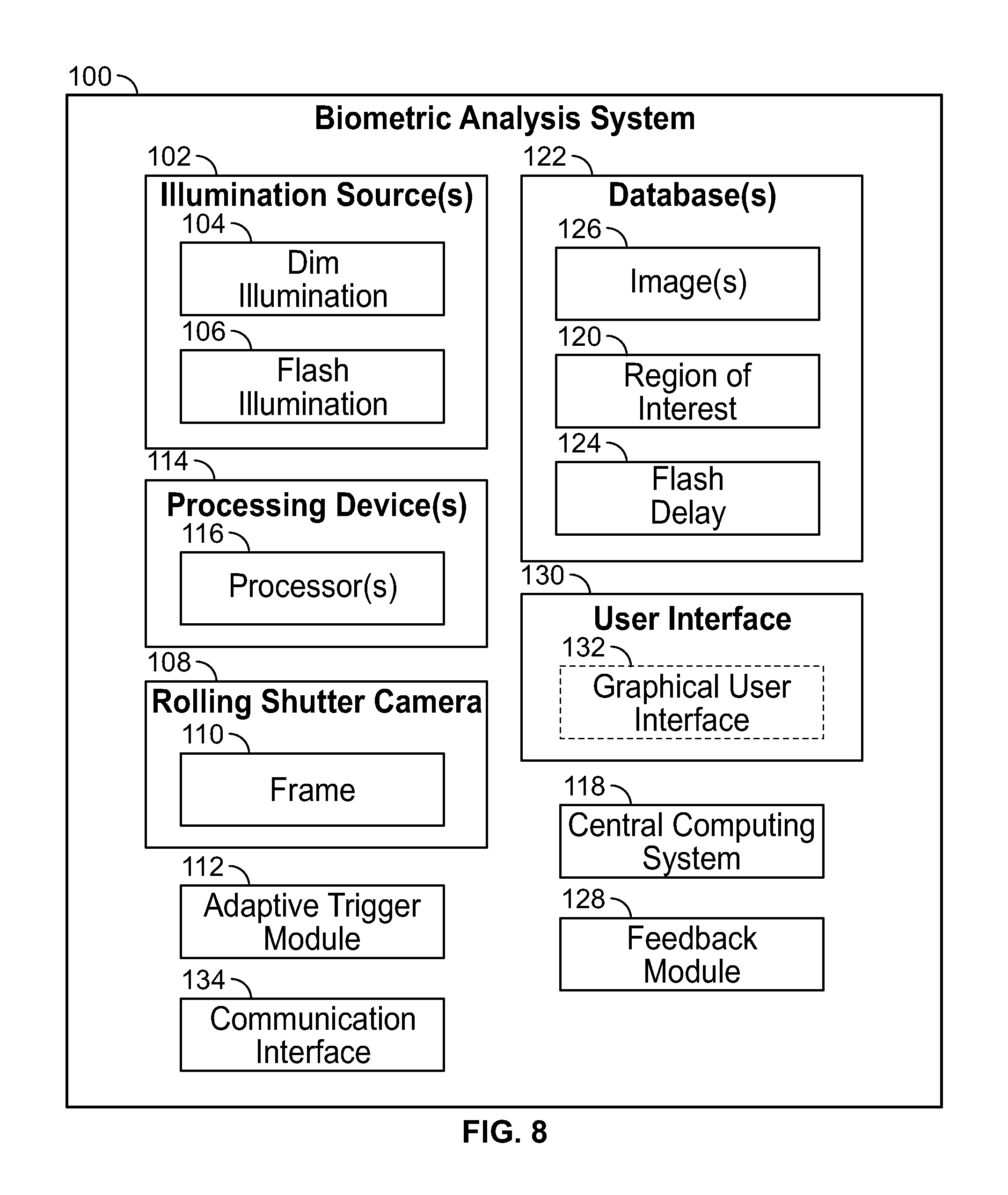
Exemplary embodiments are directed to biometric analysis systems including one or more illumination sources configured to provide dim illumination to a scene including an object and configured to provide flash illumination to the object in the scene. The biometric analysis systems include a rolling shutter camera configured to capture one or more images. The biometric analysis systems include an adaptive trigger module configured to analyze the scene to detect the object in the scene during dim illumination of the scene, determine a position in a frame of the rolling shutter camera that coincides with the detected object in the scene, and arrange a delay between a start of image writing by the rolling shutter camera and a trigger of the one or more illumination sources such that a stripe of the flash illumination coincides with the detected object in the scene.
| Inventors: | Ackerman; David Alan (Hopewell, NJ), Bergen; James R. (Hopewell, NJ), Mapen; Barry E. (Stonington, CT), Perna; Steven N. (Lawrenceville, NJ) | ||||||||||
|---|---|---|---|---|---|---|---|---|---|---|---|
| Applicant: |
|
||||||||||
| Assignee: | Princeton Identity, Inc.
(Hamilton, NJ) |
||||||||||
| Family ID: | 59961086 | ||||||||||
| Appl. No.: | 15/471,131 | ||||||||||
| Filed: | March 28, 2017 |
Prior Publication Data
| Document Identifier | Publication Date | |
|---|---|---|
| US 20170286792 A1 | Oct 5, 2017 | |
Related U.S. Patent Documents
| Application Number | Filing Date | Patent Number | Issue Date | ||
|---|---|---|---|---|---|
| 62316347 | Mar 31, 2016 | ||||
| Current U.S. Class: | 1/1 |
| Current CPC Class: | H04N 5/2256 (20130101); H04N 5/2329 (20130101) |
| Current International Class: | G06K 9/20 (20060101); H04N 7/18 (20060101); H04N 5/225 (20060101); G06K 9/00 (20060101) |
| Field of Search: | ;382/117,118,124 |
References Cited [Referenced By]
U.S. Patent Documents
| 3852592 | December 1974 | Scoville et al. |
| 3993888 | November 1976 | Fellman |
| 4109237 | August 1978 | Hill |
| 4641349 | February 1987 | Flom et al. |
| 5291560 | March 1994 | Daugman |
| 5337104 | August 1994 | Smith et al. |
| 5481622 | January 1996 | Gerhardt et al. |
| 5572596 | November 1996 | Wildes et al. |
| 5835616 | November 1998 | Lobo et al. |
| 5861940 | January 1999 | Robinson et al. |
| 5933515 | August 1999 | Pu et al. |
| 5953440 | September 1999 | Zhang et al. |
| 5966197 | October 1999 | Yee |
| 5987459 | November 1999 | Swanson et al. |
| 6055322 | April 2000 | Salganicoff et al. |
| 6081607 | June 2000 | Mori et al. |
| 6119096 | September 2000 | Mann et al. |
| 6144754 | November 2000 | Okano et al. |
| 6204858 | March 2001 | Gupta |
| 6229907 | May 2001 | Okano et al. |
| 6247813 | June 2001 | Kim et al. |
| 6252976 | June 2001 | Schildkraut et al. |
| 6301370 | October 2001 | Steffens et al. |
| 6307954 | October 2001 | Suzaki |
| 6320610 | November 2001 | Van Sant et al. |
| 6421462 | July 2002 | Christian et al. |
| 6424727 | July 2002 | Musgrave et al. |
| 6433326 | August 2002 | Levine et al. |
| 6525303 | February 2003 | Gladnick |
| 6526160 | February 2003 | Ito |
| 6542624 | April 2003 | Oda |
| 6549644 | April 2003 | Yamamoto |
| 6614919 | September 2003 | Suzaki et al. |
| 6714665 | March 2004 | Hanna et al. |
| 6765581 | July 2004 | Cheng |
| 6836554 | December 2004 | Bolle et al. |
| 6850252 | February 2005 | Hoffberg |
| 6895103 | May 2005 | Chen et al. |
| 6912298 | June 2005 | Wilensky |
| 6977989 | December 2005 | Bothe et al. |
| 7015955 | March 2006 | Funston et al. |
| 7095901 | August 2006 | Lee et al. |
| 7099495 | August 2006 | Kodno et al. |
| 7118042 | October 2006 | Moore et al. |
| 7130453 | October 2006 | Kondo et al. |
| 7146027 | December 2006 | Kim et al. |
| 7295686 | November 2007 | Wu |
| 7310443 | December 2007 | Kris et al. |
| 7380938 | June 2008 | Chmielewski, Jr. et al. |
| 7428320 | September 2008 | Northcott et al. |
| 7466308 | December 2008 | Dehlin |
| 7466847 | December 2008 | Komura |
| 7542628 | June 2009 | Lolacono et al. |
| 7574021 | August 2009 | Matey |
| 7583823 | September 2009 | Jones et al. |
| 7599524 | October 2009 | Camus et al. |
| 7627147 | December 2009 | Lolacono et al. |
| 7634114 | December 2009 | Zappia |
| 7657127 | February 2010 | Lolacono et al. |
| 7751598 | July 2010 | Matey et al. |
| 7925059 | April 2011 | Hoyos et al. |
| 8050463 | November 2011 | Hamza |
| 8170293 | May 2012 | Tosa et al. |
| 8189879 | May 2012 | Cambier |
| 8195576 | June 2012 | Grigg et al. |
| 8200980 | June 2012 | Robinson et al. |
| 8317325 | November 2012 | Raguin et al. |
| 8337104 | December 2012 | Takiguchi et al. |
| 8374404 | February 2013 | Williams et al. |
| 8553948 | October 2013 | Hanna |
| 8603165 | December 2013 | Park |
| 8639058 | January 2014 | Bergen et al. |
| 8682073 | March 2014 | Bergen |
| 8755607 | June 2014 | Bergen et al. |
| 8854446 | October 2014 | Bergen et al. |
| 8934005 | January 2015 | De Bruijn |
| 9100825 | August 2015 | Schultz et al. |
| 9131141 | September 2015 | Tinker et al. |
| 9195890 | November 2015 | Bergen |
| 9514365 | December 2016 | Tinker et al. |
| 9665772 | May 2017 | Bergen |
| 9836647 | December 2017 | Perna et al. |
| 9836648 | December 2017 | Perna et al. |
| 10025982 | July 2018 | Perna et al. |
| 2002/0080141 | June 2002 | Imai et al. |
| 2002/0118864 | August 2002 | Kondo et al. |
| 2002/0150280 | October 2002 | Li |
| 2002/0154794 | October 2002 | Cho |
| 2002/0164054 | November 2002 | McCartney et al. |
| 2002/0180586 | December 2002 | Kitson et al. |
| 2003/0046553 | March 2003 | Angelo |
| 2003/0103652 | June 2003 | Lee et al. |
| 2003/0123711 | July 2003 | Kim et al. |
| 2003/0169334 | September 2003 | Braithwaite et al. |
| 2003/0174211 | September 2003 | Imaoka et al. |
| 2004/0037452 | February 2004 | Shin |
| 2004/0088584 | May 2004 | Shachar et al. |
| 2004/0146187 | July 2004 | Jeng |
| 2004/0170304 | September 2004 | Haven |
| 2004/0213437 | October 2004 | Howard et al. |
| 2004/0236549 | November 2004 | Dalton |
| 2005/0047655 | March 2005 | Luo et al. |
| 2005/0063582 | March 2005 | Park et al. |
| 2005/0084179 | April 2005 | Hanna et al. |
| 2005/0088200 | April 2005 | Takekuma et al. |
| 2005/0210267 | September 2005 | Sugano et al. |
| 2005/0270386 | December 2005 | Saitoh et al. |
| 2006/0008125 | January 2006 | Lauper et al. |
| 2006/0028617 | February 2006 | Matsumura et al. |
| 2006/0098097 | May 2006 | Wach et al. |
| 2006/0105806 | May 2006 | Vance et al. |
| 2006/0120570 | June 2006 | Azuma et al. |
| 2006/0140454 | June 2006 | Northcott et al. |
| 2006/0150928 | July 2006 | Lehmann et al. |
| 2006/0184243 | August 2006 | Yilmaz |
| 2006/0202036 | September 2006 | Wang |
| 2006/0210123 | September 2006 | Kondo et al. |
| 2006/0222212 | October 2006 | Du et al. |
| 2006/0245623 | November 2006 | Loiacono et al. |
| 2006/0274918 | December 2006 | Amantea et al. |
| 2007/0014439 | January 2007 | Ando |
| 2007/0025598 | February 2007 | Kobayashi et al. |
| 2007/0036397 | February 2007 | Hamza |
| 2007/0047770 | March 2007 | Swope et al. |
| 2007/0140531 | June 2007 | Hamza |
| 2007/0160266 | July 2007 | Jones et al. |
| 2007/0189582 | August 2007 | Hamza et al. |
| 2007/0198850 | August 2007 | Martin et al. |
| 2007/0201728 | August 2007 | Monro |
| 2007/0206935 | September 2007 | Ono |
| 2007/0236567 | October 2007 | Pillman et al. |
| 2007/0285537 | December 2007 | Dwinell et al. |
| 2008/0049185 | February 2008 | Huffman et al. |
| 2008/0069411 | March 2008 | Friedman |
| 2008/0121721 | May 2008 | Chen et al. |
| 2008/0180544 | July 2008 | Drader |
| 2008/0187174 | August 2008 | Metaxas et al. |
| 2008/0219515 | September 2008 | Namgoong |
| 2008/0271116 | October 2008 | Robinson et al. |
| 2009/0041309 | February 2009 | Kim |
| 2009/0208064 | August 2009 | Cambier |
| 2009/0216606 | August 2009 | Coffman et al. |
| 2009/0220126 | September 2009 | Claret-Tournier et al. |
| 2009/0232418 | September 2009 | Lolacono et al. |
| 2009/0278922 | November 2009 | Tinker et al. |
| 2010/0026853 | February 2010 | Mokhnatyuk |
| 2010/0034529 | February 2010 | Jelinek |
| 2010/0046808 | February 2010 | Connell et al. |
| 2010/0063880 | March 2010 | Atsmon et al. |
| 2010/0082398 | April 2010 | Davis et al. |
| 2010/0142938 | June 2010 | Zhang |
| 2010/0176802 | July 2010 | Huguet |
| 2010/0278394 | November 2010 | Raguin et al. |
| 2010/0287053 | November 2010 | Ganong et al. |
| 2010/0290668 | November 2010 | Friedman et al. |
| 2010/0301113 | December 2010 | Bohn et al. |
| 2010/0310133 | December 2010 | Mason et al. |
| 2010/0328420 | December 2010 | Roman |
| 2011/0007205 | January 2011 | Lee |
| 2011/0043683 | February 2011 | Beach et al. |
| 2011/0075893 | March 2011 | Connel, II et al. |
| 2011/0081946 | April 2011 | Singh |
| 2011/0134268 | June 2011 | MacDonald |
| 2011/0142297 | June 2011 | Yu et al. |
| 2011/0187878 | August 2011 | Mor et al. |
| 2011/0317991 | December 2011 | Tsai |
| 2012/0086645 | April 2012 | Zheng et al. |
| 2012/0154536 | June 2012 | Stoker et al. |
| 2012/0155716 | June 2012 | Kim |
| 2012/0163783 | June 2012 | Braithwaite et al. |
| 2012/0243729 | September 2012 | Pasquero |
| 2012/0293642 | November 2012 | Berini et al. |
| 2013/0014153 | January 2013 | Bhatia et al. |
| 2013/0044199 | February 2013 | Nanu et al. |
| 2013/0051631 | February 2013 | Hanna |
| 2013/0081119 | March 2013 | Sampas |
| 2013/0083185 | April 2013 | Coleman, III |
| 2013/0089240 | April 2013 | Northcott et al. |
| 2013/0091520 | April 2013 | Chen |
| 2013/0147603 | June 2013 | Malhas et al. |
| 2013/0150120 | June 2013 | Wu et al. |
| 2013/0162798 | June 2013 | Hanna et al. |
| 2013/0188943 | July 2013 | Wu |
| 2013/0194407 | August 2013 | Kim |
| 2013/0215228 | August 2013 | Stoker et al. |
| 2013/0250085 | September 2013 | MacKinnon |
| 2013/0329115 | December 2013 | Palmeri |
| 2014/0046772 | February 2014 | Raman |
| 2014/0055337 | February 2014 | Karlsson |
| 2014/0059607 | February 2014 | Upadhyay et al. |
| 2014/0071547 | March 2014 | O'Neill et al. |
| 2014/0078389 | March 2014 | Merz |
| 2014/0161325 | June 2014 | Bergen |
| 2014/0171150 | June 2014 | Hurst et al. |
| 2014/0232930 | August 2014 | Anderson |
| 2014/0327815 | November 2014 | Auger |
| 2014/0369575 | December 2014 | Riopka et al. |
| 2015/0037935 | February 2015 | Kim et al. |
| 2015/0098629 | April 2015 | Perna et al. |
| 2015/0098630 | April 2015 | Perna et al. |
| 2015/0126245 | May 2015 | Barkan et al. |
| 2015/0193666 | July 2015 | Derakhshani et al. |
| 2015/0227790 | August 2015 | Smits |
| 2015/0286864 | October 2015 | Gottemukkula et al. |
| 2015/0338915 | November 2015 | Publicover et al. |
| 2015/0379325 | December 2015 | Tinker et al. |
| 2016/0012218 | January 2016 | Perna et al. |
| 2016/0012275 | January 2016 | Bergen |
| 2016/0012292 | January 2016 | Perna et al. |
| 2016/0014121 | January 2016 | Perna et al. |
| 2016/0117544 | April 2016 | Hoyos et al. |
| 2016/0148384 | May 2016 | Bud et al. |
| 2016/0274660 | September 2016 | Publicover et al. |
| 2016/0345818 | December 2016 | Suzuki et al. |
| 2016/0364609 | December 2016 | Ivanisov et al. |
| 2017/0111568 | April 2017 | Hsieh et al. |
| 2017/0124314 | May 2017 | Laumea |
| 2017/0132399 | May 2017 | Pawluk et al. |
| 2017/0286790 | October 2017 | Mapen et al. |
| 2017/0286792 | October 2017 | Ackerman et al. |
| 2017/0323167 | November 2017 | Mapen et al. |
| 2017/0337439 | November 2017 | Ackerman et al. |
| 2017/0337440 | November 2017 | Green et al. |
| 2017/0337441 | November 2017 | Mapen et al. |
| 2017/0347000 | November 2017 | Perna et al. |
| 2018/0025244 | January 2018 | Bohl et al. |
| 2018/0165537 | June 2018 | Ackerman |
| 102708357 | Oct 2012 | CN | |||
| 103048848 | Apr 2013 | CN | |||
| 103099624 | May 2013 | CN | |||
| 0821912 | Feb 1998 | EP | |||
| 1324259 | Jul 2003 | EP | |||
| 2007011667 | Jan 2007 | JP | |||
| 2008-538425 | Oct 2008 | JP | |||
| 4372321 | Nov 2009 | JP | |||
| 2003-0066512 | Aug 2003 | KR | |||
| 10-2011-0134848 | Dec 2011 | KR | |||
| WO-1996/19132 | Jun 1996 | WO | |||
| WO-1997/14873 | Apr 1997 | WO | |||
| WO-1997/21188 | Jun 1997 | WO | |||
| WO-1998/08439 | Mar 1998 | WO | |||
| WO-1999/31183 | Jun 1999 | WO | |||
| WO-2000/39760 | Jul 2000 | WO | |||
| WO-2013/056001 | Apr 2013 | WO | |||
| WO-2014/093227 | Jun 2014 | WO | |||
| WO-2014/100250 | Jun 2014 | WO | |||
| WO-2015/102704 | Jul 2015 | WO | |||
| WO-2017/172695 | Oct 2017 | WO | |||
| WO-2017/173228 | Oct 2017 | WO | |||
Other References
|
US. Appl. No. 15/475,425, filed Mar. 31, 2017, Published. cited by applicant . U.S. Appl. No. 15/514,098, filed Mar. 24, 2017, Published. cited by applicant . U.S. Appl. No. 15/531,922, filed May 31, 2017, Published. cited by applicant . U.S. Appl. No. 15/661,188, filed Jul. 27, 2017, Published. cited by applicant . U.S. Appl. No. 15/661,246, filed Jul. 27, 2017, Published. cited by applicant . U.S. Appl. No. 15/661,267, filed Jul. 27, 2017, Published. cited by applicant . U.S. Appl. No. 15/661,297, filed Jul. 27, 2017, Published. cited by applicant . U.S. Appl. No. 15/661,340, filed Jul. 27, 2017, Published. cited by applicant . U.S. Appl. No. 15/944,327, filed Apr. 3, 2018, Published. cited by applicant . Pending U.S. Appl. No. 16/039,442, filed Jul. 19, 2018. cited by applicant . U.S. Appl. No. 15/839,020, filed Dec. 12, 2017, Published. cited by applicant . Annapoorani et al., Accurate and Fast Iris Segmentation. International Journal of Engineering Science and Technology. 2010;2(6):1492-1499. cited by applicant . Arfken, G., "Mathematical Methods for Physicists," Academic Press, NY 6.sup.th Ed. (2005). cited by applicant . Atos Origin, "UK Passport Service, Biometrics Enrollment Trial." Atos Origin Report (May 2005). cited by applicant . Bertalmio et al., Navier-Stokes, Fluid Dynamics, and Image and Video Inpainting. Proceedings of the 2001 IEEE Computer Society Conferenc on Computer Vision and Pattern Recognition. CVPR 2001, 8 pages, (2001). cited by applicant . Betke, et al., "Preliminary Investigation of Real-time Monitoring of a Driver in City Traffic," IEEE Intelligent Vehicles Syposium, Oct. 3-5, 2000, Dearborn, MI, 563-568. cited by applicant . Boehnen et al., A Multi-Sample Standoff Multimodal Biometric System, Theory, Aoolications and Systems (BTAS), Sep. 23, 2012, pp. 127-134. cited by applicant . Bowyer et al., Image Understanding for Iris Biometrics: A Survey. Computer Vision and Image Understanding. 2008;110:281-307. cited by applicant . Braithwaite, Michael et al., "Application-Specific Biometric Templates," AutoID 2002 Workshop, Tarrytown, NY, pp. 1-10 (2002). cited by applicant . Burt, et al., "The Laplacian Pyramid as a Compact Image Code," IEEE Transactions on Communications, 31(4): 532-540, 1983. cited by applicant . Canadian Offic Action for Application 2,833, 740 dated Jan. 15, 2018. cited by applicant . Office Action dated Oct. 30, 2018, issued in connection with U.S. Appl. No. 15/514,098 (35 pages). cited by applicant . Daugman John, "How Iris Recognition Works," IEEE Transactions on Circuits and Systems for Video Teohnology, vol. 14, No. 1 (Jan. 2004). cited by applicant . Daugman, J., "High confidence visual recognition of persons by a test of statistical independence", IEEE Transactions on Pattern Analysis and Machine Intelligence, 15 (11), pp. 1148-1161 (1993). cited by applicant . Daugman, J., "Recognizing Persons by Their Iris Patterns," in Biometrics: Personal Indentification in a Networked Society, A.K.Jain, et al., eds. Kluwer Academic Pub. 1999. cited by applicant . Daugman, John et al., "Iris recognition border-crossing system in the UAE," International Airport Review, Issue 2 (2004). cited by applicant . Daugman, John."How Iris Recognition Works" .Jun. 13, 2003. IEEE Transactions on Circuits and Systems for Video technology, vol. 14, No. 1. cited by applicant . Daugman, The Importance of Being Random: Statistical Principles of Iris Recognition. Pattern Recognition. Pre-publication version. 13 pages, Dec. 21, 2001. cited by applicant . DellaVecchia, et al., "Methodology and apparatus for using the human iris as a robust biometric," Ophthalmic Technologies VIII, SPIE Biomedical Optics Society, Photonics West Conference, San Jose, CA Jan. 24, 1998. cited by applicant . Du et al., Analysis of Partial Iris Recognition Using a 1-D Approach. Proceedings, IEEE International Conference on Acoustics, Speech, and Signal Processing. Mar. 18-23, 2005;2;961-964. cited by applicant . European Office Action for Application 12719332.4 dated Jan. 29, 2018. cited by applicant . European Search Report for Apllication 14876521.7 dated Oct. 19, 2017. cited by applicant . Extended European Search Report in connection with European Patent Application No. 15864635.6 dated Jun. 6, 2018 (8 pages). cited by applicant . Fan, et al., "An Efficient Automatic Iris Image Acquisition and Preprocessing System," Proceedings of the 2006 IEEE International Conference on Mechatronics and Automation, pp. 1779-1784 (6 pages). cited by applicant . Final Office Action dated Aug. 18, 2016 from U.S. Appl. No. 14/858,715, filed Sep. 18, 2015 (6 pages). cited by applicant . Final Office Action dated Aug. 4, 2016 from U.S. Appl. No. 14/509,366, filed Oct. 8, 2014 (24 pages). cited by applicant . Final Office Action dated Mar. 21, 2017 from U.S. Appl. No. 14/863,936, filed Sep. 24, 2015 (17 pages). cited by applicant . Final Office Action dated Mar. 22, 2017 from U.S. Appl. No. 14/863,950, filed Sep. 24, 2015 (16 pages). cited by applicant . Final Office Action dated Mar. 22, 2017 from U.S. Appl. No. 14/863,960, filed Sep. 24, 2015 (21 pages). cited by applicant . Final Office Action for U.S. Appl. No. 10/818,307, dated Jan. 21, 2009, 28 pages. cited by applicant . Final Office Action for U.S. Appl. No. 10/818,307, dated Jan. 30, 2008, 19 pages. cited by applicant . Final Office Action for U.S. Appl. No. 11/377,042, dated Nov. 14, 2008, 20 pages. cited by applicant . Final Office Action for U.S. Appl. No. 11/510,197, dated May 5, 2009, 16 pages. cited by applicant . Final Office Action for U.S. Appl. No. 12/464,369, dated Aug. 5, 2014, 22 pages. cited by applicant . Final Office Action for U.S. Appl. No. 12/464,369, dated Oct. 3, 2012, 27 pages. cited by applicant . Final Office Action for U.S. Appl. No. 12/576,644, dated Oct. 13, 2010, 11 pages. cited by applicant . Final Office Action for U.S. Appl. No. 14/100,615, dated Sep. 1, 2015, 22 pages. cited by applicant . Final Office Action for U.S. Appl. No. 14/509,356, dated Sep. 28, 2016, 20 pages. cited by applicant . Final Office Action for U.S. Appl. No. 14/509,366, dated Aug. 4, 2016, 29 pages. cited by applicant . Final Office Action for U.S. Appl. No. 14/846,090, dated Jun. 15, 2016, 17 pages. cited by applicant . Final Office Action for U.S. Appl. No. 14/858,715, dated Aug. 18, 2016, 29 pages. cited by applicant . Final Office Action for U.S. Appl. No. 14/858,715, dated Aug. 18, 2016, 6 pages. cited by applicant . Final Office Action for U.S. Appl. No. 14/863,936, dated Mar. 21, 2017, 17 pages. cited by applicant . Final Office Action for U.S. Appl. No. 14/863,950, dated Mar. 22, 2017, 16 pages. cited by applicant . Final Office Action for U.S. Appl. No. 14/863,960, dated Mar. 22, 2017, 21 pages. cited by applicant . First Japanese Office Action for Application 2015-545911 dated Feb. 26, 2018 ( with English translation). cited by applicant . FIT Validation Studies, http://www.pmifit.com/validation.htm, Mar. 2, 2004. cited by applicant . Google Scholar Search--"Rida Hadma" pp. 1 of 2. cited by applicant . Haro, et al., "Detecting and Tracking Eyes by Using Their Physological Properties, Dynamics and Appearance," CVPR 2000, 163-168. cited by applicant . Hutchinson, et al., "Human-Computer Interaction Using Eye-Gaze Input," IEEE Transaction on Systems, Man and Cybernetics, 19(6): 1527-1534, 1989. cited by applicant . International Biometrics Group, "Independent Testing of Iris Recognition Technology, Final Report," Study Commissioned by the US Department of Homeland Security (May 2005). cited by applicant . International Preliminary Report on Patentability for Application No. PCT/US2015/051863, dated Mar. 28, 2017, 6 pages. cited by applicant . International Search Report and Written Opinion for Application No. PCT/US17/13110, dated May 18, 2017, 12 pages. cited by applicant . International Search Report and Written Opinion for Application No. PCT/US2013/073887, dated Mar. 20, 2014, 11 pages. cited by applicant . International Search Report and Written Opinion for Application No. PCT/US2017/025303, dated Jun. 16, 2017, 11 pages. cited by applicant . International Search Report and Written Opinion for PCT/US2017/24444 dated Jun. 19, 2017 pp. 1-15. cited by applicant . International Search Report and Written Opinion for PCT/US2018/042807, dated Sep. 27, 2018, pp. 1-19. cited by applicant . International Search Report and Written Opinionf for PCT/US2017/025303 dated Jun. 16, 2017. cited by applicant . International Search Report for Application No. PCT/US2015/051863, dated Dec. 10, 2015, 1 page. cited by applicant . International Search Report for Application No. PCT/US2017/065793, dated Feb. 16, 2018, 3 pages. cited by applicant . International Search Report for PCT/US2015061024, dated Mar. 31, 2016. cited by applicant . International Search Report of the International Searching Authority dated Jun. 28, 2018, issued in connection with International Application No. PCT/US2018/025895 (3 pages). cited by applicant . Iwai, Daisuke, Shoichiro Mihara, and Kosuke Sato. "Extended depth-of-field projector by fast focal sweep projection." IEEE transactions on visualization and computer graphics 21.4 (2015): 462-470. cited by applicant . Jacob, R., "The Use of Eye Movements in Human-Computer Interaction Techniques: What you Look at is What you Get," ACM Trans. Info.Sys., 9(3):152-169. cited by applicant . Japanese Office Action for Application No. 2015-545911, dated Feb. 20, 2018, 6 pages. cited by applicant . Li, Zexi, "An Iris Recognition Algorithm Based on Coarse and Fine Location," 2017 IEEE 2nd International Conference on Big Data Analysis, pp. 744-747 (4 pages). cited by applicant . Ma et al., "Efficient Iris Recognition by Characterizing Key Local Variations", IEEE Transactions on Image Processing, vol. 13, No. 6, Jun. 2004, 12 pages. cited by applicant . Ma., et al. "Iris Recognition Using Circular Symmetric Filters," Pattern Recognition, 2002, Proceedings 16th International Conference on vol. 2 IEEE, 2002 (4 pages). cited by applicant . Ma., et al., "Iris Recognition Based on Multichannel Gabor Filtering" ACCV2002: The 5th Asian Conference on Computer Vision, Jan. 23-25, 2002, Melbourne, Australia (5 pages). cited by applicant . Mansfield, Tony et al., "Biometric Product Testing Final Report," CESG Contract X92A/4009309, CESG/BWG Biometric Test Programme; Centre for Mathematics & Scientific Computing, National Physical Laboratory (2001). cited by applicant . Matey et al., Iris on the Move: Acquisition of Images for Iris Recognition in Less Constrained Environments. Proceedings of the IEEE. Nov. 2006;94(11):1936-1947. cited by applicant . Miyazawa et al., Iris Recognition Algorithm Based on Phase-Only Correlation, The Institute of Image Information and Television Engineers, JapanJun. 27, 2006, vol. 30, No. 33, pp. 45-48. cited by applicant . Monro et al., An Effective Human Iris Code with Low Complexity. IEEE International Conference on Image Processing. Sep. 14, 2005;3:277-280. cited by applicant . Narayanswamy, et al., "Extended Depth-of-Field Iris Recognition System for a Workstation Environment," Proc. SPIE. vol. 5779 (2005) (10 pages). cited by applicant . Negin, et al., "An Iris Biometric System for Public and Personal Use," IEEE Computer, pp. 70-75, Feb. 2000. cited by applicant . Nguyen, et al., "Quality-Driven Super-Resolution for Less Constrained Iris Recognition at a Distance and on the Move," IEEE Transactions on Information Forensics and Security 6.4 (2011) pp. 1248-1558 (11 pages). cited by applicant . Non-Final Office Action for U.S. Appl. No. 10/809,471, dated Mar. 19, 2007, 12 pages. cited by applicant . Non-Final Office Action for U.S. Appl. No. 10/818,307, dated Jul. 10, 2008, 28 pages. cited by applicant . Non-Final Office Action for U.S. Appl. No. 10/818,307, dated Mar. 20, 2007, 22 pages. cited by applicant . Non-Final Office Action for U.S. Appl. No. 11/334,968, dated Jan. 6, 2009, 28 pages. cited by applicant . Non-Final Office Action for U.S. Appl. No. 11/377,042, dated Apr. 8, 2009, 22 pages. cited by applicant . Non-Final Office Action for U.S. Appl. No. 11/377,042, dated Jan. 7, 2008, 13 pages. cited by applicant . Non-Final Office Action for U.S. Appl. No. 11/510,197, dated Oct. 10, 2008, 36 pages. cited by applicant . Non-Final Office Action for U.S. Appl. No. 11/510,197, dated Oct. 8, 2009, 21 pages. cited by applicant . Non-Final Office Action for U.S. Appl. No. 11/849,969, dated Dec. 19, 2008, 17 pages. cited by applicant . Non-Final Office Action for U.S. Appl. No. 11/857,432, dated Dec. 30, 2008, 23 pages. cited by applicant . Non-Final Office Action for U.S. Appl. No. 12/429,695, dated Sep. 2, 2009, 11 pages. cited by applicant . Non-Final Office Action for U.S. Appl. No. 12/464,369, dated Jan. 2, 2015, 23 pages. cited by applicant . Non-Final Office Action for U.S. Appl. No. 12/464,369, dated May 9, 2012, 33 pages. cited by applicant . Non-Final Office Action for U.S. Appl. No. 12/576,644, dated Jul. 14, 2010, 14 pages. cited by applicant . Non-Final Office Action for U.S. Appl. No. 13/096,716, dated May 23, 2013, 16 pages. cited by applicant . Non-Final Office Action for U.S. Appl. No. 13/096,724, dated Jan. 16, 2014, 29 pages. cited by applicant . Non-Final Office Action for U.S. Appl. No. 13/096,728, dated May 7, 2013, 33 pages. cited by applicant . Non-Final Office Action for U.S. Appl. No. 13/096,728, dated Nov. 8, 2012, 37 pages. cited by applicant . Non-Final Office Action for U.S. Appl. No. 14/100,615, dated Mar. 4, 2015, 19 pages. cited by applicant . Non-Final Office Action for U.S. Appl. No. 14/509,356, dated Feb. 29, 2016, 19 pages. cited by applicant . Non-Final Office Action for U.S. Appl. No. 14/509,356, dated Mar. 16, 2017, 21 pages. cited by applicant . Non-Final Office Action for U.S. Appl. No. 14/509,366, dated Feb. 21, 2017, 25 pages. cited by applicant . Non-Final Office Action for U.S. Appl. No. 14/509,366, dated Mar. 3, 2016, 40 pages. cited by applicant . Non-Final Office Action for U.S. Appl. No. 14/846,090, dated Jan. 7, 2016, 35 pages. cited by applicant . Non-Final Office Action for U.S. Appl. No. 14/858,715, dated Mar. 14, 2016, 37 pages. cited by applicant . Non-Final Office Action for U.S. Appl. No. 14/863,936, dated Aug. 4, 2016, 16 pages. cited by applicant . Non-Final Office Action for U.S. Appl. No. 14/863,936, dated Sep. 26, 2017, 28 pages. cited by applicant . Non-Final Office Action for U.S. Appl. No. 14/863,950, dated Aug. 3, 2016, 15 pages. cited by applicant . Non-Final Office Action for U.S. Appl. No. 14/863,950, dated Sep. 26, 2017, 22 pages. cited by applicant . Non-Final Office Action for U.S. Appl. No. 14/863,960, dated Aug. 3, 2016, 21 pages. cited by applicant . Non-Final Office Action for U.S. Appl. No. 14/863,960, dated Sep. 28, 2017, 28 pages. cited by applicant . Non-Final Office Action for U.S. Appl. No. 15/475,425, dated Jul. 12, 2018, 31 pages. cited by applicant . Non-Final Office Action for U.S. Appl. No. 15/531,922, dated Jun. 12, 2018, 17 pages. cited by applicant . Non-Final Office Action for for U.S. Appl. No. 12/464,369, dated Feb. 27, 2014, 25 pages. cited by applicant . Notice of Allowance dated Feb. 1, 2017 from U.S. Appl. No. 14/858,715, filed Sep. 18, 2015 (8 pages). cited by applicant . Notice of Allowance for U.S. Appl. No. 10/809,471, dated Mar. 24, 2008, 14 pages. cited by applicant . Notice of Allowance for U.S. Appl. No. 10/809,471, dated Oct. 5, 2007, 11 pages. cited by applicant . Notice of Allowance for U.S. Appl. No. 10/818,307, dated May 18, 2009, 8 pages. cited by applicant . Notice of Allowance for U.S. Appl. No. 11/334,968, dated Apr. 17, 2009, 11 pages. cited by applicant . Notice of Allowance for U.S. Appl. No. 11/377,042, dated Sep. 8, 2009, 16 pages. cited by applicant . Notice of Allowance for U.S. Appl. No. 11/510,197, dated Feb. 1, 2010, 13 pages. cited by applicant . Notice of Allowance for U.S. Appl. No. 11/849,969, dated Aug. 20, 2009, 21 pages. cited by applicant . Notice of Allowance for U.S. Appl. No. 11/849,969, dated Jul. 10, 2009, 18 pages. cited by applicant . Notice of Allowance for U.S. Appl. No. 11/857,432, dated Jun. 17, 2009, 17 pages. cited by applicant . Notice of Allowance for U.S. Appl. No. 12/429,695, dated Dec. 15, 2009, 7 pages. cited by applicant . Notice of Allowance for U.S. Appl. No. 12/429,695, dated Nov. 17, 2009, 12 pages. cited by applicant . Notice of Allowance for U.S. Appl. No. 12/464,369, dated May 8, 2015, 29 pages. cited by applicant . Notice of Allowance for U.S. Appl. No. 12/576,644, dated Dec. 10, 2010, 14 pages. cited by applicant . Notice of Allowance for U.S. Appl. No. 13/096,716, dated Oct. 30, 2013, 25 pages. cited by applicant . Notice of Allowance for U.S. Appl. No. 13/096,724, dated Aug. 19, 2014, 17 pages. cited by applicant . Notice of Allowance for U.S. Appl. No. 13/096,728, dated Feb. 7, 2014, 33 pages. cited by applicant . Notice of Allowance for U.S. Appl. No. 13/096,735, dated Jun. 24, 2013, 24 pages. cited by applicant . Notice of Allowance for U.S. Appl. No. 13/096,735, dated Oct. 4, 2013, 26 pages. cited by applicant . Notice of Allowance for U.S. Appl. No. 14/100,615, dated Sep. 28, 2015, 22 pages. cited by applicant . Notice of Allowance for U.S. Appl. No. 14/509,356, dated Aug. 1, 2017, 29 pages. cited by applicant . Notice of Allowance for U.S. Appl. No. 14/509,366, dated Jul. 31, 2017, 59 pages. cited by applicant . Notice of Allowance for U.S. Appl. No. 14/846,090, dated Jul. 25, 2016, 22 pages. cited by applicant . Notice of Allowance for U.S. Appl. No. 14/858,715, dated Feb. 1, 2017, 42 pages. cited by applicant . Notice of Allowance for U.S. Appl. No. 14/858,715, dated Feb. 1, 2017, 8 pages. cited by applicant . Notice of Allowance for U.S. Appl. No. 14/858,715, dated Mar. 1, 2017, 13 pages. cited by applicant . Notice of Allowance for U.S. Appl. No. 14/863,936, dated Mar. 20, 2018, 9 pages. cited by applicant . Notice of Allowance for U.S. Appl. No. 14/863,950, dated Mar. 27, 2018, 9 pages. cited by applicant . Notice of Allowance for U.S. Appl. No. 14/863,960, dated Mar. 20, 2018, 9 pages. cited by applicant . Office Action dated Aug. 3, 2016 from U.S. Appl. No. 14/863,950, filed Sep. 24, 2015 (15 pages). cited by applicant . Office Action dated Aug. 3, 2016 from U.S. Appl. No. 14/863,960, filed Sep. 24, 2015 (21 pages). cited by applicant . Office Action dated Aug. 4, 2016 from U.S. Appl. No. 14/863,936, filed Sep. 24, 2015 (16 pages). cited by applicant . Office Action dated Feb. 21, 2017 from U.S. Appl. No. 14/509,366, filed Oct. 8, 2014 (25 pages). cited by applicant . Office Action dated Mar. 14, 2016 from U.S. Appl. No. 14/858,715, filed Sep. 18, 2015 (9 pages). cited by applicant . Office Action dated Mar. 3, 2016 from U.S. Appl. No. 14/509,366, filed Oct. 8, 2014 (19 pages). cited by applicant . Ortiz et al., An Optimal Strategy for Dilation Based Iris Image Enrollment. IEEE International Joint Conference on Biometrics. 6 pages, Sep. 29-Oct. 2, 2014. cited by applicant . Restriction Requirement for U.S. Appl. No. 11/510,197, dated May 16, 2008, 12 pages. cited by applicant . Robert J.K. Jakob, "Eye Movement Based Human Computer Interaction Techniques; Toward Non-Command Interfaces," Advances in Human-Computer Interaction, vol. 4, ed. by H.R. Hartson and D. Hix, pp. 151-190, Ablex Publishing Co., Norwood, N.J. (1993). cited by applicant . Robert J.K. Jakob, "Eye Tracking in Advanced Interface Design," in Virtual Environments and Advanced Interface Dseign, ed. by W. Barfield and T.A. Furness, pp. 258-288, Oxford University Press, New York (1995). cited by applicant . Roth, Mouthpiece Meditations, Part 3. Online Trombone Journal, www.trombone.org. 5 pages, Jul. 23, 2018. cited by applicant . Schovanec, Ocular Dynamics and Skeletal Systems, IEEE Control Systems Magazine. Aug. 2001;21(4):70-79. cited by applicant . Scoblete, The Future of the Electronic Shutter. pdn, Photo District News, retrieved online at: https://www.pdnonline.com/gear/cameras/the-future-of-the-electronic-shutt- er/, 6 pates, May 9, 2016. cited by applicant . Second Japanese Office Action for Application 2015-545911 dated Feb. 26, 2018 ( with English translation). cited by applicant . Singapore Search Report and Written Report for Application No. 11201704097X, dated Mar. 13, 2018, 5 pages. cited by applicant . SRI International, "Seeing the Future of Iris Recognition", available at www.sri.com/iom, Mar. 2014, 9 pages. cited by applicant . Swiniarski, Experiments on Human Recognition Using Error Backpropagation Artificial Neural Network. Neural Networks Class (CS553) of San Diego State University Computer Science Department, Apr. 2004. cited by applicant . Tan et al., Efficient Iris Recognition by Characterizing Key Local Variations. IEEE Transactions on Image Processing. Jun. 2004;13(6):739-750. cited by applicant . U.S. Appl. No. 14/100,615, "Iris Biometric Matching System", filed Dec. 9, 2013, 57 pages. cited by applicant . U.S. Appl. No. 14/100,615, "Iris Biometric Matching System," filed Dec. 9, 2013, 61 pages. cited by applicant . U.S. Appl. No. 61/888,130, filed Oct. 8, 2013, 20 pages. cited by applicant . Van der Wal, et al., "The Acadia Vision Processor," IEEE International Workshop on Computer Architecture for Machine Perception, pp. 31-40, Padova, Italy, Sep. 11-13, 2000. cited by applicant . Weisstein E. et al.; "Circle" From MathWorld--A Wolfram Web Resource. www.mathworld.wolfram.com/circle.html, pp. 1 to 8., Jul. 3, 2008. cited by applicant . Wildes, R., "Iris Recognition: An Emerging Biometric Technology," Proc. IEEE, 85(9):1348-1363, Sep. 1997. cited by applicant . Written Opinion for Application No. PCT/US2015/051863, dated Dec. 10, 2015, 5 pages. cited by applicant . Written Opinion for Application No. PCT/US2017/065793, dated Feb. 16, 2018, 10 pages. cited by applicant . Written Opinion for PCT/US2015061024, dated Mar. 21, 2016. cited by applicant . Written Opinion of the International Searching Authority dated Jun. 28, 2018, issued in connection with International Application No. PCT/US2018/025895 (10 pages). cited by applicant . www.m-w.com--definition- "ellipse" (Refer to Ellipse Illustration; also attached) pp. 1 of 2. cited by applicant . Yokoya, Ryunosuke, and Shree K. Nayar. "Extended depth of field catadioptric imaging using focal sweep." Proceedings of the IEEE International Conference on Computer Vision. 2015. cited by applicant . Zhu, et al., "Biometric Personal Identification Based on Iris Patterns," Pattern Recognition, Proceedings 15th International Conference on vol. 2 IEEE (2000) (4 pages). cited by applicant . International Search Report and Written Opinion for Application No. PCT/US17/24444 dated Jun. 19, 2017 (9 pages). cited by applicant . Daugman, John, The Importance of Being Random: Statistical Principles of Iris Recognition, The Journal of the Pattern Recognition, PR1656, 2001, pp. 1-13. cited by applicant . Scoblete, Greg, The Future of the Electronic Shutter, Photo District News, May 9, 2016, pp. 1-6. cited by applicant. |
Primary Examiner: Mariam; Daniel G
Attorney, Agent or Firm: McCarter & English, LLP
Parent Case Text
CROSS-REFERENCE TO RELATED APPLICATIONS
The present application claims the benefit of priority to U.S. Provisional Patent Application No. 62/316,347, filed Mar. 31, 2016, which is hereby incorporated by reference in its entirety.
Claims
What is claimed is:
1. A biometric analysis system, comprising: one or more illumination sources configured to provide dim illumination to a scene including an object and configured to provide flash illumination to the object in the scene; a rolling shutter camera configured to capture one or more images; and an adaptive trigger module configured to (i) analyze the scene to detect the object in the scene during dim illumination of the scene, (ii) determine a position in a frame of the rolling shutter camera that coincides with the detected object in the scene, and (iii) arrange a delay between a start of image writing by the rolling shutter camera and a trigger of the one or more illumination sources such that a stripe of the flash illumination coincides with the detected object in the scene.
2. The biometric analysis system of claim 1, wherein the adaptive trigger module is configured to track movement of the object within a field-of-view of the rolling shutter camera.
3. The biometric analysis system of claim 2, wherein the adaptive trigger module is configured to modify the delay between the start of image writing by the rolling shutter camera and the trigger of the one or more illumination sources based on detected movement of the object within the field-of-view.
4. The biometric analysis system of claim 1, wherein the adaptive trigger module is configured to detect a region of interest of the object and arranges the delay such that the stripe of flash illumination coincides with the detected region of interest of the object.
5. The biometric analysis system of claim 4, wherein the region of interest of the object includes eyes of a person.
6. The biometric analysis system of claim 1, wherein the object is a person, and wherein the adaptive trigger module comprises a face finder configured to detect a face of the person.
7. The biometric analysis system of claim 1, wherein the object is a physical item, and the adaptive trigger module comprises an identifier finder configured to detect a unique identifier associated with the physical item.
8. The biometric analysis system of claim 7, wherein the unique identifier is a barcode or a quick response (QR) code.
9. The biometric analysis system of claim 1, wherein the one or more illumination sources are configured to provide the flash illumination as a synchronized pulse of flash illumination.
10. The biometric analysis system of claim 1, wherein the flash illumination provided by the one or more illumination sources is brighter than the dim illumination provided by the one or more illumination sources.
11. The biometric analysis system of claim 1, wherein the one or more illumination sources comprise a first illumination source configured to provide the dim illumination and a second illumination source configured to provide the flash illumination.
12. The biometric analysis system of claim 1, wherein the one or more illumination sources are near infrared illumination sources.
13. The biometric analysis system of claim 1, wherein the one or more illumination sources are ambient light.
14. The biometric analysis system of claim 1, wherein the adaptive trigger module is configured to sweep an illuminated stripe down the frame as the rolling shutter camera captures the one or more images, analyzes an illuminated section of the one or more images to identify a region of interest in the illuminated section, and stops sweeping of the illuminated stripe when the region of interest is identified.
15. The biometric analysis system of claim 1 provided as a smartphone having said one or more illumination sources, said rolling shutter camera, and said adaptive trigger module.
16. A biometric analysis system, comprising: one or more illumination sources configured to provide dim illumination to a scene including a subject and configured to provide flash illumination to the subject in the scene; a rolling shutter camera configured to capture one or more images; and an adaptive trigger module configured to (i) analyze the scene to detect eyes of the subject in the scene during dim illumination of the scene, (ii) identify the eyes of the subject as a region of interest, (iii) determine a position in a frame of the rolling shutter camera that coincides with the identified region of interest, and (iv) arrange a flash pulse delay between a start of image writing by the rolling shutter camera and a trigger of the one or more illumination sources such that a stripe of the flash illumination coincides with the identified region of interest.
17. The biometric analysis system of claim 16, wherein the flash pulse delay ensures that the illuminated region of interest is maintained in a center of the frame of the rolling shutter camera.
18. The biometric analysis system of claim 16, comprising a feedback module configured to analyze a captured image of the region of interest and determine if the region of interest is illuminated by the stripe of the flash illumination.
19. The biometric analysis system of claim 18, wherein the adaptive trigger module is configured to adjust the flash pulse delay based on the determination of the feedback module to ensure that the region of interest is illuminated by the stripe of the flash illumination.
20. The biometric analysis system of claim 16 provided as a smartphone having said one or more illumination sources, said rolling shutter camera, and said adaptive trigger module.
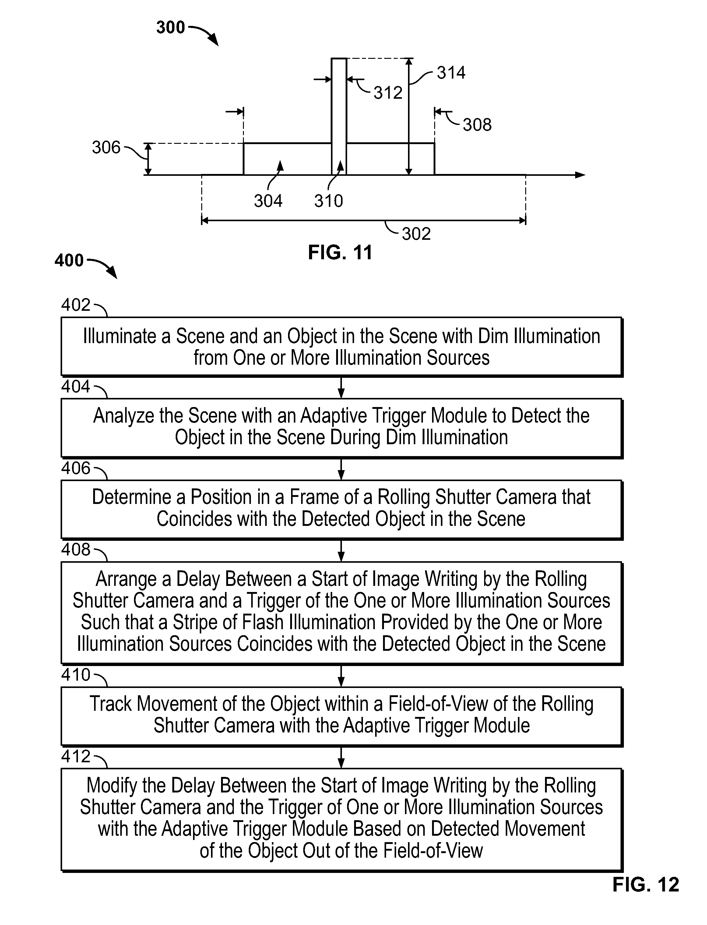
21. A method of biometric analysis, comprising: illuminating a scene and an object in the scene with dim illumination from one or more illumination sources; analyzing the scene with an adaptive trigger module to detect the object in the scene during dim illumination; determining a position in a frame of a rolling shutter camera that coincides with the detected object in the scene; and arranging a delay between a start of image writing by the rolling shutter camera and a trigger of the one or more illumination sources such that a stripe of flash illumination provided by the one or more illumination sources coincides with the detected object in the scene.
22. The method of claim 21, comprising tracking movement of the object within a field-of-view of the rolling shutter camera with the adaptive trigger module.
23. The method of claim 22, comprising modifying the delay between the start of image writing by the rolling shutter camera and the trigger of the one or more illumination sources with the adaptive trigger module based on detected movement of the object within the field-of-view.
24. A non-transitory computer-readable medium storing instructions for biometric analysis that are executable by a processing device, wherein execution of the instructions by the processing device causes the processing device to: illuminate a scene and an object in the scene with dim illumination from one or more illumination sources; analyze the scene with an adaptive trigger module to detect the object in scene during dim illumination; determine a position in a frame of a rolling shutter camera that coincides with the detected object in the scene; and arrange a delay between a start of image writing by the rolling shutter camera and a trigger of the one or more illumination sources such that a stripe of flash illumination provided by the one or more illumination sources coincides with the detected object in the scene.
Description
TECHNICAL FIELD
The present disclosure relates to systems and methods of biometric analysis and, in particular, to biometric analysis systems including an adaptive trigger configured to align an object (e.g., a subject, a barcode, or the like) within a camera field-of-view to improve application of flash illumination to the desired area of the object for capture and analysis.
BACKGROUND
Security is a concern in a variety of transactions involving private information. As an example, iris recognition is a well-accepted and accurate means of biometric identification used in government and commercial systems around the world that enables secure transactions and an added layer of security beyond keys and/or passwords. Due to the increased security provided by iris recognition systems, an increase in use of such systems has occurred around the world.
Traditional cameras used in biometric identification are generally expensive. Video cameras that use complementary metal-oxide-semiconductor (CMOS) or semiconductor charge-coupled device (CCD) image sensors typically use electronic shutters to determine the time period over which the sensor measures light. A trigger signal opens the shutter for a predetermined time during which each pixel within the sensor array collects (integrates) incoming light. At the end of the exposure, the signal collected (integrated) in each pixel during the exposure remains fixed and is then systematically read out, converted to a digital signal, and processed to become an image. Pixels are then cleared and readied for the next exposure to light.
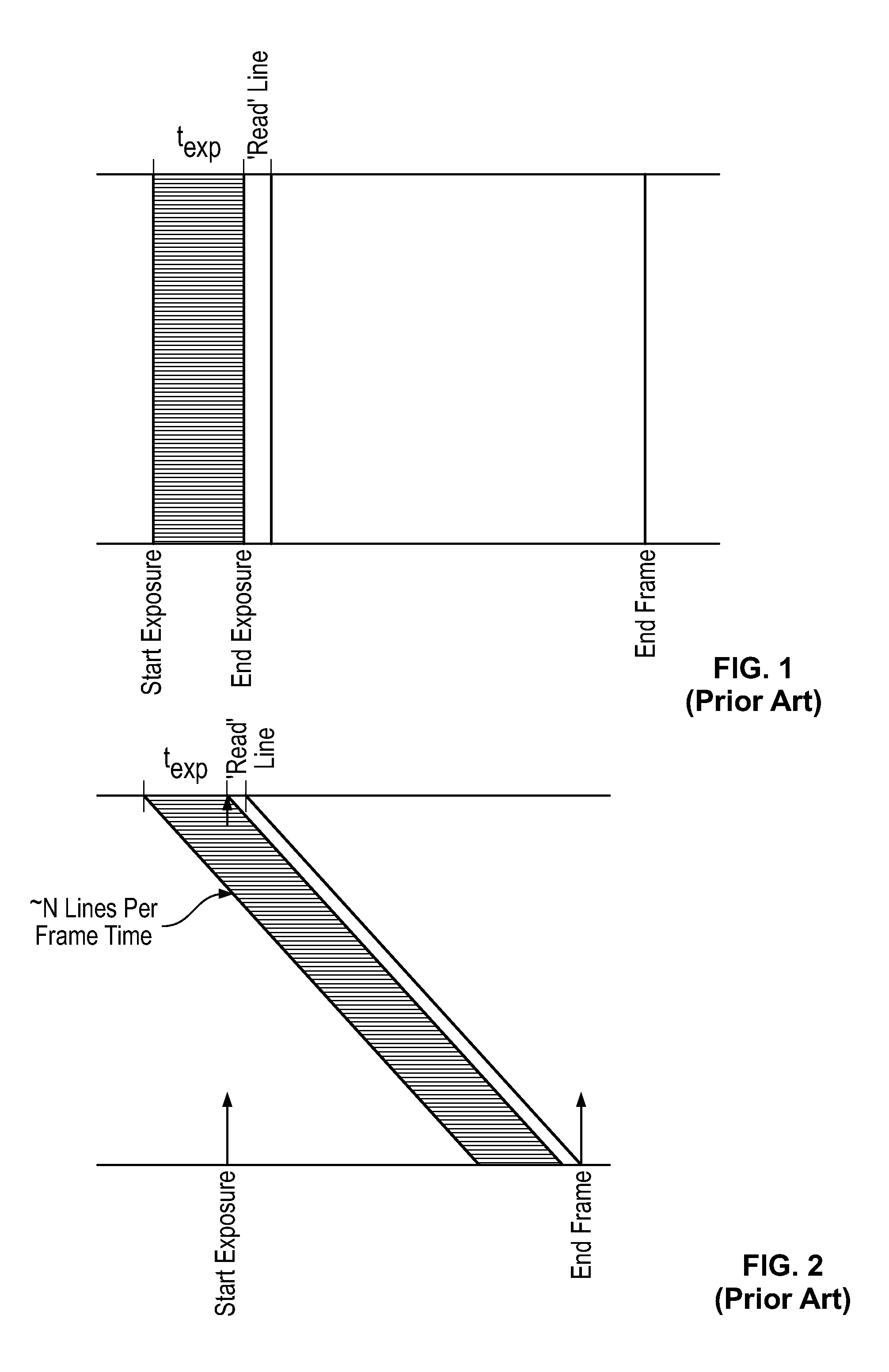
There are different types of electronic shutters used in the industry. FIG. 1 is a diagram of a traditional global shutter camera schedule of events for signal collection, including the timeline for exposure of each row of an image sensor in the global shutter camera. Global shutters simultaneously expose an entire array of pixels, e.g., N rows by M columns, during signal collection. During a single exposure event (during t.sub.exp), light is simultaneously collected in each pixel. When the global shutter closes, the light signal within each pixel represents the image during the period of the single exposure. All pixels integrate signal over exactly the same period of time. Global shutter cameras avoid flash timing issues incurred when using rolling shutter cameras. However, global shutter cameras are expensive options for biometric analysis, thereby increasing the overall costs associated with biometric analysis systems.
Rolling shutter cameras save cost and size in their sensor design. FIG. 2 is a diagram of a traditional rolling shutter schedule of events for signal collection, including the rolling shutter timeline. Rolling shutters expose an array of pixels differently from global shutters. A rolling shutter system exposes a first row of pixels for an exposure time (t.sub.exp) and then commences to read-out the exposed row of pixels for digitization. The read-out process occupies a unique onboard resource for a period referred to as a read-out time during which no other row can be read-out. To minimize the duration of the total exposure including the read-out process, the rolling shutter exposes the second row of pixels during a time that is equal to but delayed from the first row by a read-out time. The second row is thereby exposed to light and ready to be read-out at the moment that the read-out process for the first row is complete. The third row is exposed to light for a time interval equal in length to that of the first two rows but delayed relative to the second row by a read-out time allowing for the required time to read-out the second row. The process "rolls" down the pixel array reading row-by-row in sequence taking a total time equal to the exposure time for a single row plus the read-out time interval, times the number of rows. The time interval during which a row is exposed and therefore the events captured by that row are different for each row for a rolling shutter sensor. This is a key difference from a global shutter sensor, especially when using a short flash.
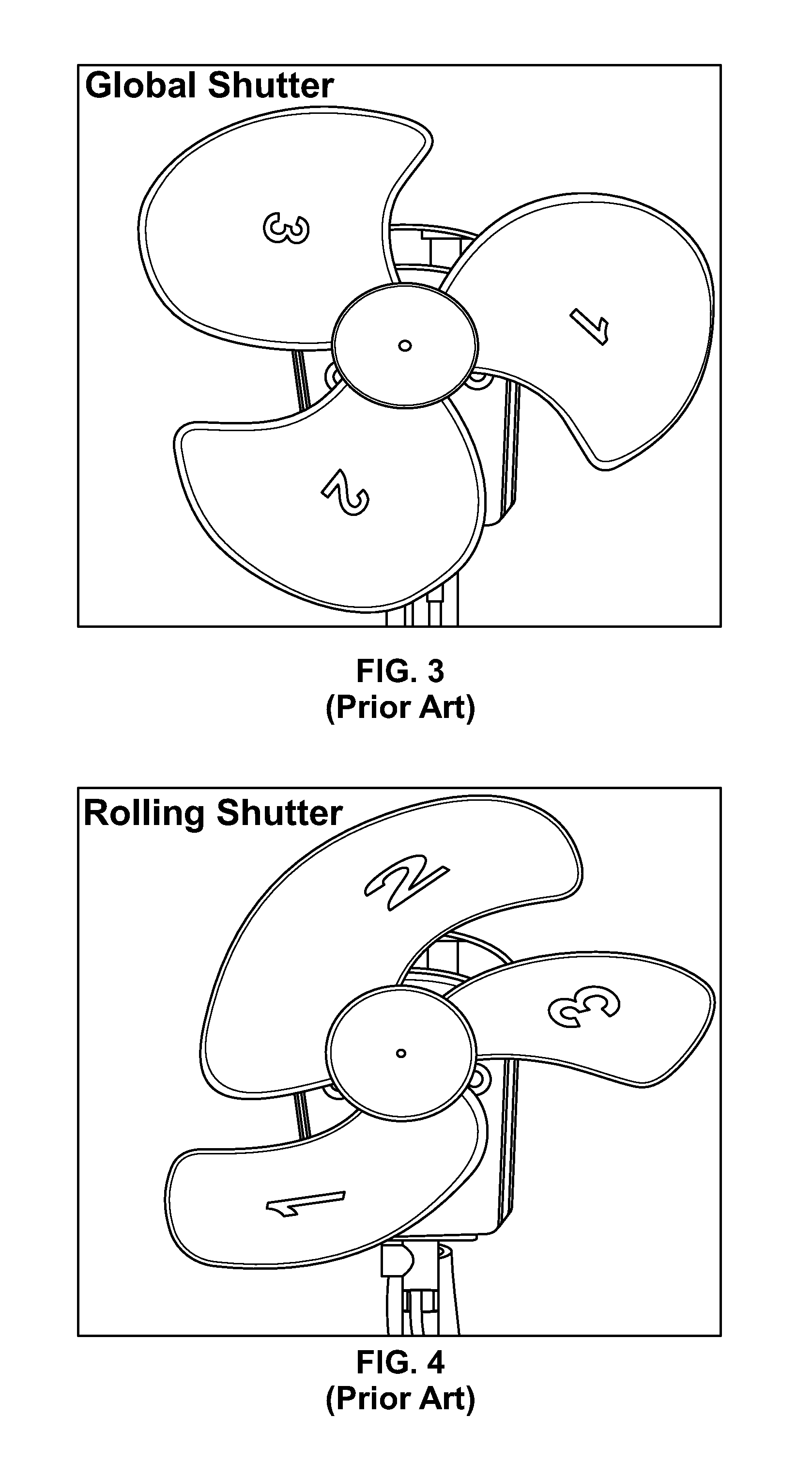
As shown in FIGS. 1 and 2, the light collection time period for each row of a sensor with a global shutter is simultaneous while the time periods of light collection for each row of a sensor equipped with a rolling shutter are not simultaneous. Rather, light collection time periods for each row of a rolling shutter are offset from one another with a delay between rows equal to the row read-out time. The different exposure techniques result in image shearing. For example, FIG. 3 shows an image in which a moving fan blade was captured by an image sensor with a global shutter with no or little distortion as compared to the same moving fan captured by an image sensor with a rolling shutter shown in FIG. 4. Image shearing is an inevitable consequence of the row-by-row time delays built into a rolling shutter sensor in which each row "sees" the scene over a slightly different and offset time interval.
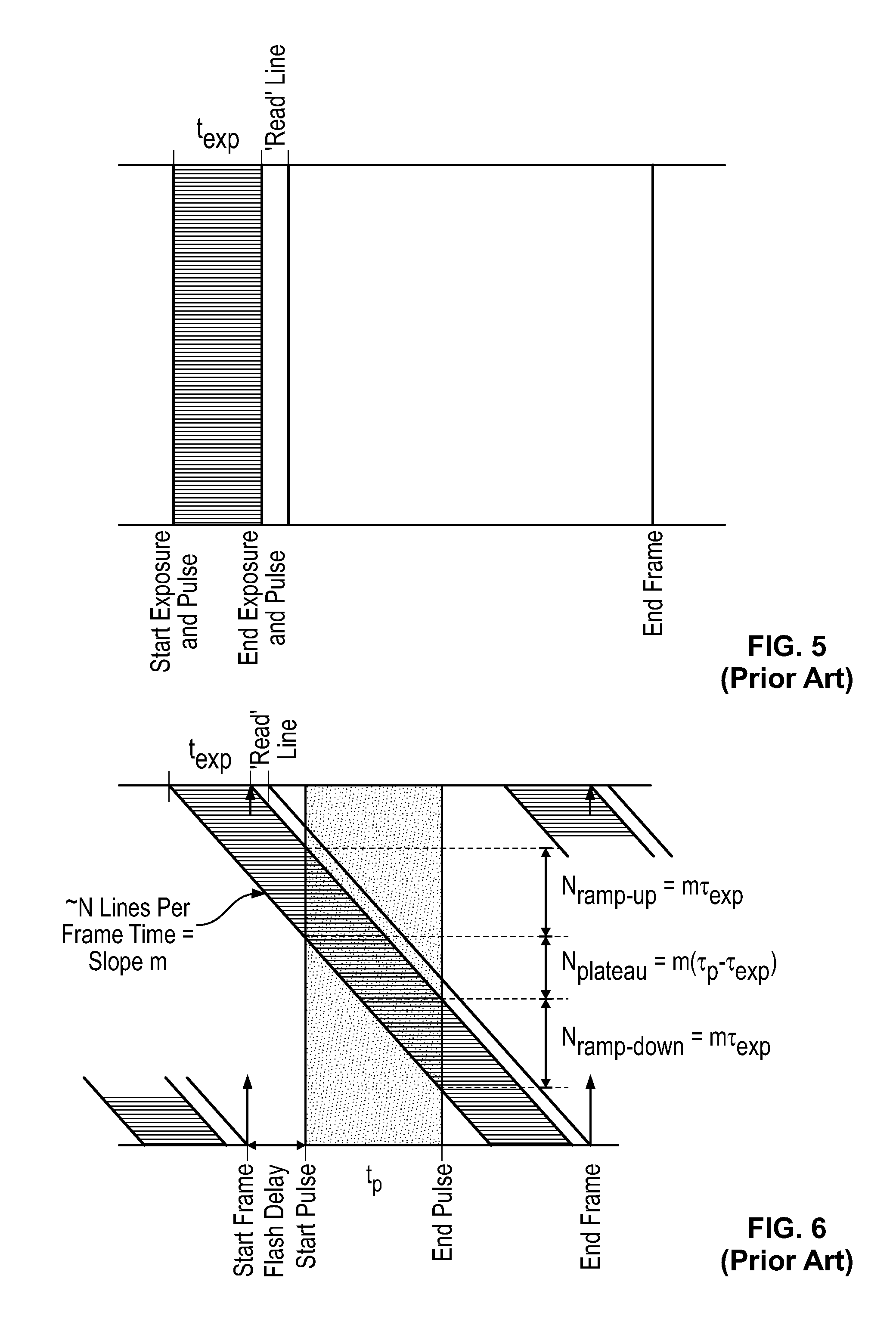
The row-by-row delay in exposure of a rolling shutter also has an effect on coordinating an exposure with flash illumination. As discussed herein, a flash refers to a short, intense period of illumination of a subject during which the light applied by the flash dominates other sources of light on the scene (e.g., the area surrounding the subject). FIG. 5 shows the exposure of each row during t.sub.exp with the shaded region indicating the duration of time of the flash illumination occurring simultaneous during t.sub.exp. In a global shutter, the exposure of all the pixels in a sensor can be coordinated with the application of the flash illumination to the scene. For example, if the period of the flash pulse is 1 ms, the global shutter can open simultaneously with the start of the pulse and close simultaneously with the end of the pulse 1 ms later. The flash illuminates the pixels during and only during their global exposure. Light forming the image is, by assumption, dominated by the light applied to the scene by the flash. If, for example, sunlight is present in the scene, the irradiance on the object from the flash is significantly brighter than that of the sunlight during the flash pulse when pixels are exposed by the global shutter.
Coordinating a flash pulse with a rolling shutter exposure is more complicated than with a global shutter. FIG. 6 shows the rolling shutter exposure during t.sub.exp for each row extending diagonally across the diagram, and the time period for flash illumination illustrated as the vertical shaded region t.sub.p. After a flash delay, the flash pulse occurs between the start pulse and end pulse points of the diagram. Because the exposure period for each row is delayed from the previous row by a short read-out time interval, illumination of a full frame requires that a flash pulse provide illumination during a period when all rows are integrating light. Failure to meet this condition creates a situation in which some rows of pixels integrate light from the flash pulse while some do not, and perhaps some rows integrate light from only a portion of the flash pulse. In this case, the image is unevenly illuminated. As shown in FIG. 6, some rows are finished integrating before the flash starts and other rows do not start integrating until after the flash ends. In addition, other rows integrate a partial flash and some integrate the full flash. Thus, a subset of lines on the rolling shutter sensor receive adequate illumination, but outside of this set of lines, the other parts of the sensor remain largely dark.
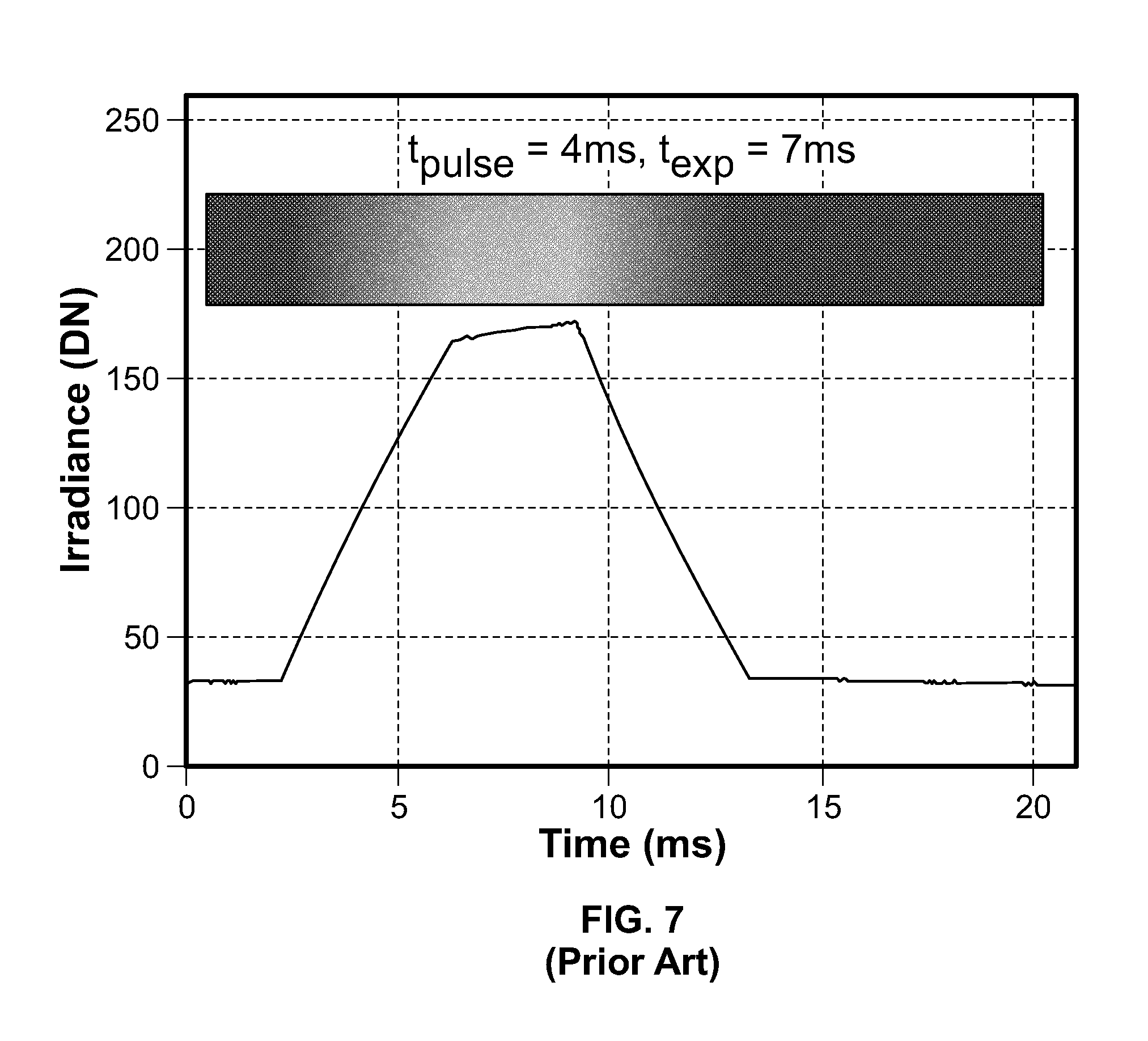
One example of a short flash pulse can be considered with respect to FIG. 6, which, across the top horizontal line, four horizontal dashed lines, and bottom lines, respectively shows row numbers 0, 200, 450, 600, 850, and 1000. The flash pulse can start as row 200 of 1000 rows finishes integrating the signal and begins to read-out, indicated by the top dashed line. The flash pulse can end as row 850 of 1000 begins integrating the signal, indicated by the bottom dashed line. FIG. 6 shows that rows 450 through 599 receive the full illumination of the flash pulse, as bracketed by the middle two dashed lines. However, rows 200 to 449 and rows 600 to 849 only receive a portion of the flash illumination while rows outside of these ranges, e.g., rows 1 to 199 and 850 to 1000, receive no flash illumination. Assuming insignificant ambient light, the resulting image would show an illumination stripe surrounded by dim regions. The transition from bright to dim at the top and bottom of the stripe is due to rows that receive flash illumination over a fraction of the total pulse time. FIG. 7 shown a portion of an image acquired using a rolling shutter camera with a delayed flash pulse in which the recorded irradiance is plotted to show dark regions before and after the flash, ramp-up and ramp-down regions of partial illumination, and a plateau region of complete flash illumination. The plateau region of FIG. 7 is not flat because the flash itself was not uniform over the field-of-view. As another example, an image captured using a rolling shutter camera would include a horizontal stripe with a vertical height proportional to the duration of the flash illumination. In cases with bright ambient illumination, the un-flashed portion of the image would appear, but might be significantly dimmer if the flash illumination is brighter than the ambient illumination.
When an image of a particular object is desired with a rolling shutter camera, a trigger signal can be initiated by the sensor controller to fire the flash at a preset time relative to the start of image writing. For example, the flash can fire when the first line is written and can remain on for 50 of 1000 lines. The resultant image would be flash illuminated for the top 5% of the image and would be dark elsewhere. The same flash can be delayed until the 500.sup.th line of 1000 lines, resulting in an image with a stripe of illuminated content approximately halfway down the frame. With such an arrangement, the photographer would need to align the subject within the camera field-of-view such that the stripe of illumination detected by the sensor corresponds to the position of the desired object.
Traditionally, one solution to the problem of flash illuminating an image using a rolling shutter has been to use an extended period of illumination, e.g., a flash pulse that is started simultaneously with the beginning of the exposure of the first row of pixels and is not finished until the last row of pixels has been exposed. The extended period of illumination is needed to expose the entire image since image lines are written sequentially rather than all at once (as is the case with a camera including a more expensive and physically larger global shutter sensor). This technique necessitates a longer flash pulse compared to the global shutter case, and would show up in FIG. 6 as a shaded region covering all of the rows with a duration equal to the frame time. This technique would also illuminate the full frame shown in FIG. 7. Additional requirements on the flash in terms of power output, heating and reliability are needed based on the longer pulse for this technique. A longer pulse might also challenge requirements for eye-safety. For these reasons, full frame pulses with rolling shutters are considered impractical.
Thus, a need exists for improved biometric analysis systems including a rolling shutter that are capable of illuminating and capturing the desired area of an object for identification without an extended flash. These and other needs are addressed by the systems and methods of biometric analysis of the present disclosure.
SUMMARY
In accordance with embodiments of the present disclosure, an exemplary biometric analysis system is provided that includes one or more illumination sources configured to provide dim illumination to a scene including an object, and further configured to provide flash illumination to the object in the scene. In some embodiments, the dim illumination can be provided by an illumination source external and separate from the biometric analysis system, such as ambient light, sunlight, any other light source, or the like (e.g., one or more of the illumination sources can be ambient light). In some embodiments, the biometric analysis system can include a single illumination source that provides the dim illumination, with the same illumination source providing the flash illumination at the determined time period. In some embodiments, the biometric analysis system can include a first illumination source that provides the dim illumination, and a second (separate) illumination source that provides the flash illumination. In some embodiments, the first illumination source can continue to provide the dim illumination during the flash illumination from the second illumination source. In some embodiments, the first illumination source can be automatically actuated into a non-illuminating configuration during the flash illumination provided by the second illumination source, and automatically actuated into an illuminating configuration after the flash illumination is complete.
The biometric analysis system includes a rolling shutter camera configured to capture one or more images. The rolling shutter camera generally includes a frame with a field-of-view. The term "image" as used herein can include still frame images, video, combinations thereof, or the like. The biometric analysis system includes an adaptive trigger module configured to be executed by a controller or processing device. The adaptive trigger module, when executed, can be configured to analyze the scene to detect the object in the scene during dim illumination of the scene. The adaptive trigger module, when executed, can be configured to determine a position in the frame of the rolling shutter camera that coincides with the detected object in the scene. The adaptive trigger module, when executed, can be configured to arrange a delay (a time delay) between a start of image writing by the rolling shutter camera and a trigger of the one or more illumination sources such that a stripe of the flash illumination coincides with the detected object in the scene.
In some embodiments, the adaptive trigger module, when executed, can be configured to track movement of the object within a field-of-view of the rolling shutter camera. In such embodiments, the adaptive trigger module can be configured to modify the delay between the start of image writing by the rolling shutter camera and the trigger of the one or more illumination sources based on detected movement of the object within the field-of-view.
In some embodiments, the adaptive trigger module can be configured to detect a region of interest of the object and arranges the delay such that the stripe of flash illumination coincides with the detected region of interest of the object. In one embodiment, the region of interest of the object can include one or both eyes of a person.
In some embodiments, the object can be a person. In such embodiments, the adaptive trigger module includes a face finder configured to detect a face (and/or features of the face) of the person. In some embodiments, the object can be a physical item. In such embodiments, the adaptive trigger module can include an identifier finder configured to detect a unique identifier (e.g., a barcode, a quick response (QR) code, combinations thereof, or the like) associated with the physical item.
In some embodiments, the one or more illumination sources can be configured to provide the flash illumination as a synchronized pulse of flash illumination. The flash illumination provided by the one or more illumination sources is brighter than the dim illumination provided by the one or more illumination sources. In one embodiment, the one or more illumination sources can be near infrared (NIR) illumination sources. In some embodiments, the adaptive trigger module can be configured to sweep an illuminated stripe down the frame as the rolling shutter camera captures the one or more images, analyze an illuminated section of the one or more images to identify a region of interest in the illuminated section, and stop sweeping of the illuminated stripe when the region of interest is identified.
In accordance with embodiments of the present disclosure, an exemplary biometric analysis system is provided that includes one or more illumination sources configured to provide dim illumination to a scene including a subject and configured to provide flash illumination to the subject in the scene. The biometric analysis system includes a rolling shutter camera configured to capture one or more images. The biometric analysis system includes an adaptive trigger module configured to be executed by a controller or processing device. The adaptive trigger module, when executed, can be configured to analyze the scene to detect eyes of the subject in the scene during dim illumination of the scene. The adaptive trigger module, when executed, can be configured to identify the eyes of the subject as a region of interest. The adaptive trigger module, when executed, can be configured to determine a position in a frame of the rolling shutter camera that coincides with the identified region of interest. The adaptive trigger module, when executed, can be configured to arrange a flash pulse delay between a start of image writing by the rolling shutter camera and a trigger of the one or more illumination sources such that a stripe of the flash illumination coincides with the identified region of interest. In some embodiments, rather than or in addition to using dim illumination, the adaptive trigger module can be executed to search and find the region of interest by systematically sweeping an illuminated stripe down the field-of-view and stopped when a region of interest is detected. Thus, rather than using a single frame (as in dim illumination), the illuminated stripe can be a fraction in width of the full frame and is advanced across the field-of-view, thereby using multiple frames to detect the region of interest. The region of interest can be tracked by the adaptive trigger module after being detected.
The flash pulse delay can ensure that the illuminated region of interest is substantially maintained in a center of the frame of the rolling shutter camera. The biometric analysis system can include a feedback module configured to be executed by the controller or processing device. The feedback module, when executed, can be configured to analyze a captured image of the region of interest and determine if the region of interest is illuminated by the stripe of the flash illumination. The adaptive trigger module, when executed, can be configured to adjust the flash pulse delay based on the determination of the feedback module to ensure that the region of interest is illuminated by the stripe of the flash illumination.
In accordance with embodiments of the present disclosure, an exemplary method of biometric analysis is provided. The method includes illuminating a scene and an object in the scene with dim illumination from one or more illumination sources. The method includes analyzing the scene with an adaptive trigger module to detect the object in scene during dim illumination. The method includes determining a position in a frame of a rolling shutter camera that coincides with the detected object in the scene. The method includes arranging a delay between a start of image writing by the rolling shutter camera and a trigger of the one or more illumination sources such that a stripe of flash illumination provided by the one or more illumination sources coincides with the detected object in the scene.
In some embodiments, the method can include tracking movement of the object within a field-of-view of the rolling shutter camera with the adaptive trigger module. In such embodiments, the method can include modifying the delay between the start of image writing by the rolling shutter camera and the trigger of the one or more illumination sources with the adaptive trigger module based on detected movement of the object within the field-of-view.
In accordance with embodiments of the present disclosure, an exemplary non-transitory computer-readable medium storing instructions for biometric analysis is provided. Execution of the instructions by a processing device (or controller) causes the processing device to illuminate a scene and an object in the scene with dim illumination from one or more illumination sources. Execution of the instructions by a processing device causes the processing device to analyze the scene with an adaptive trigger module to detect the object in scene during dim illumination. Execution of the instructions by a processing device causes the processing device to determine a position in a frame of a rolling shutter camera that coincides with the detected object in the scene. Execution of the instructions by a processing device causes the processing device to arrange a delay between a start of image writing by the rolling shutter camera and a trigger of the one or more illumination sources such that a stripe of flash illumination provided by the one or more illumination sources coincides with the detected object in the scene.
Other objects and features will become apparent from the following detailed description considered in conjunction with the accompanying drawings. It is to be understood, however, that the drawings are designed as an illustration only and not as a definition of the limits of the invention.
BRIEF DESCRIPTION OF THE DRAWINGS
To assist those of skill in the art in making and using the disclosed systems and methods of biometric analysis, reference is made to the accompanying figures, wherein:
FIG. 1 (prior art) is a diagram of a traditional global shutter camera schedule of events showing simultaneous exposure of each row between start and end of exposure followed by simultaneous read-out.
FIG. 2 (prior art) is a diagram of a traditional rolling shutter camera schedule of events showing start of frame, cascading exposure of pixel rows, and rolling read-out, with delay between rows being equal to read-out time.
FIG. 3 (prior art) is an image of a moving fan illustrating minimal distortion as captured by a traditional global shutter camera.
FIG. 4 (prior art) is an image of a moving fan illustrating shearing distortion effects caused by cascading row delays as captured by a traditional rolling shutter camera.
FIG. 5 (prior art) is a diagram of a traditional global shutter schedule of events showing simultaneous exposure of each row between start and end of exposure followed by simultaneous read-out, with a flash firing during the same time interval as that in which the rows are exposed (t.sub.exp).
FIG. 6 (prior art) is a diagram of a traditional rolling shutter schedule of events showing start of frame, cascading exposure of pixel rows, and rolling read-out, with a flash firing after the beginning of the frame, illuminating some but not all rows, and some rows partially but others completely, resulting in a ramp-up, plateau and ramp-down periods of flash illumination.
FIG. 7 (prior art) is a diagram of a vertical strip of an image (re-oriented horizontally to align with the time axis) showing dark, ramp-up, plateau, ramp-down, and another dark region due to timing of flash in a traditional rolling shutter frame.
FIG. 8 is a schematic block diagram of an exemplary biometric analysis system in accordance with the present disclosure.
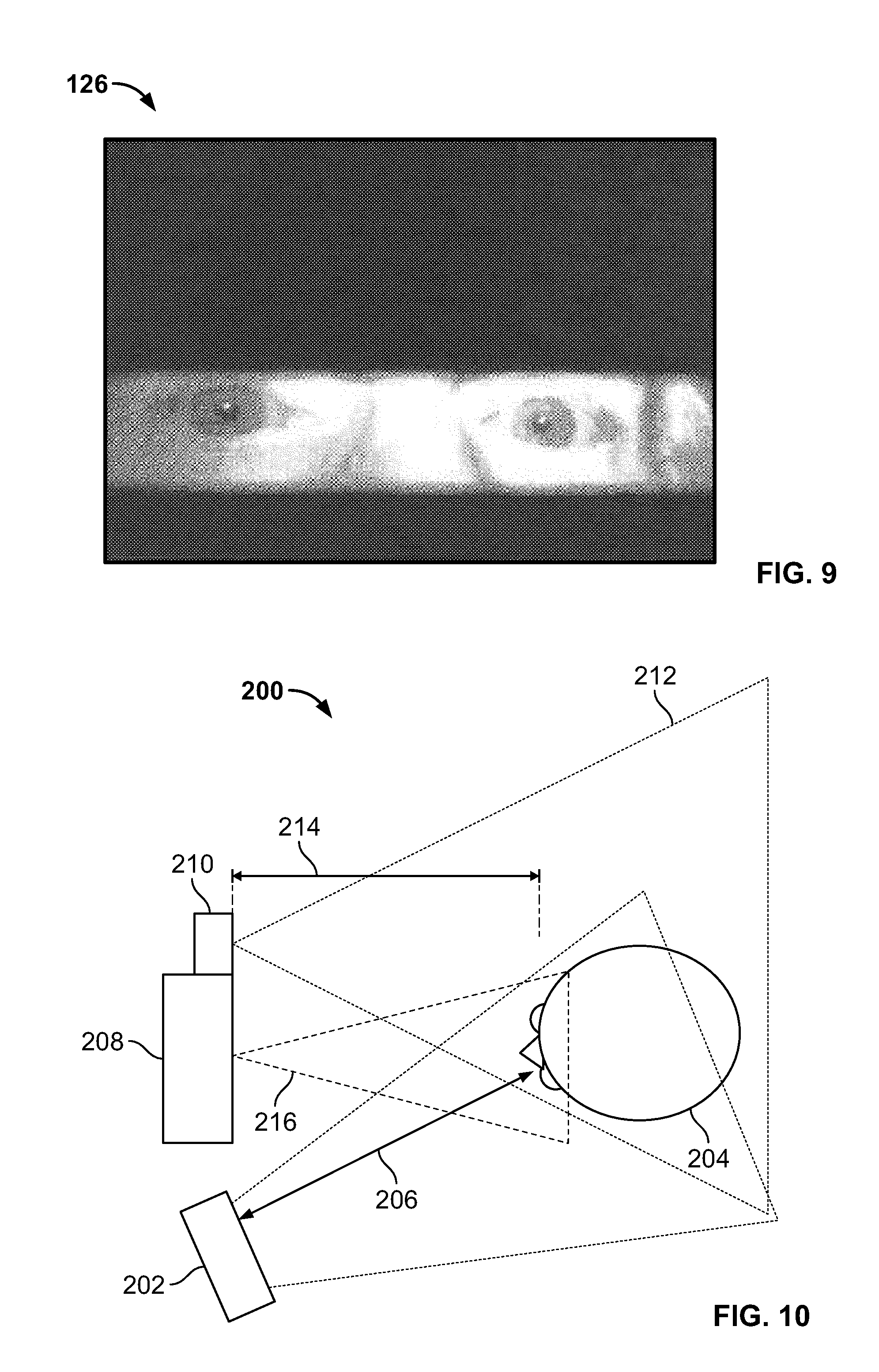
FIG. 9 is a representation of an image captured by a rolling shutter camera of the exemplary biometric analysis system including a stripe of flash illumination across a region of interest.
FIG. 10 is a diagrammatic view of an exemplary biometric analysis system in accordance with the present disclosure.
FIG. 11 is a diagrammatic view of a frame action of a rolling shutter camera of an exemplary biometric analysis system in accordance with the present disclosure.
FIG. 12 is a flowchart illustrating an exemplary process of implementing an exemplary biometric analysis system in accordance with the present disclosure.
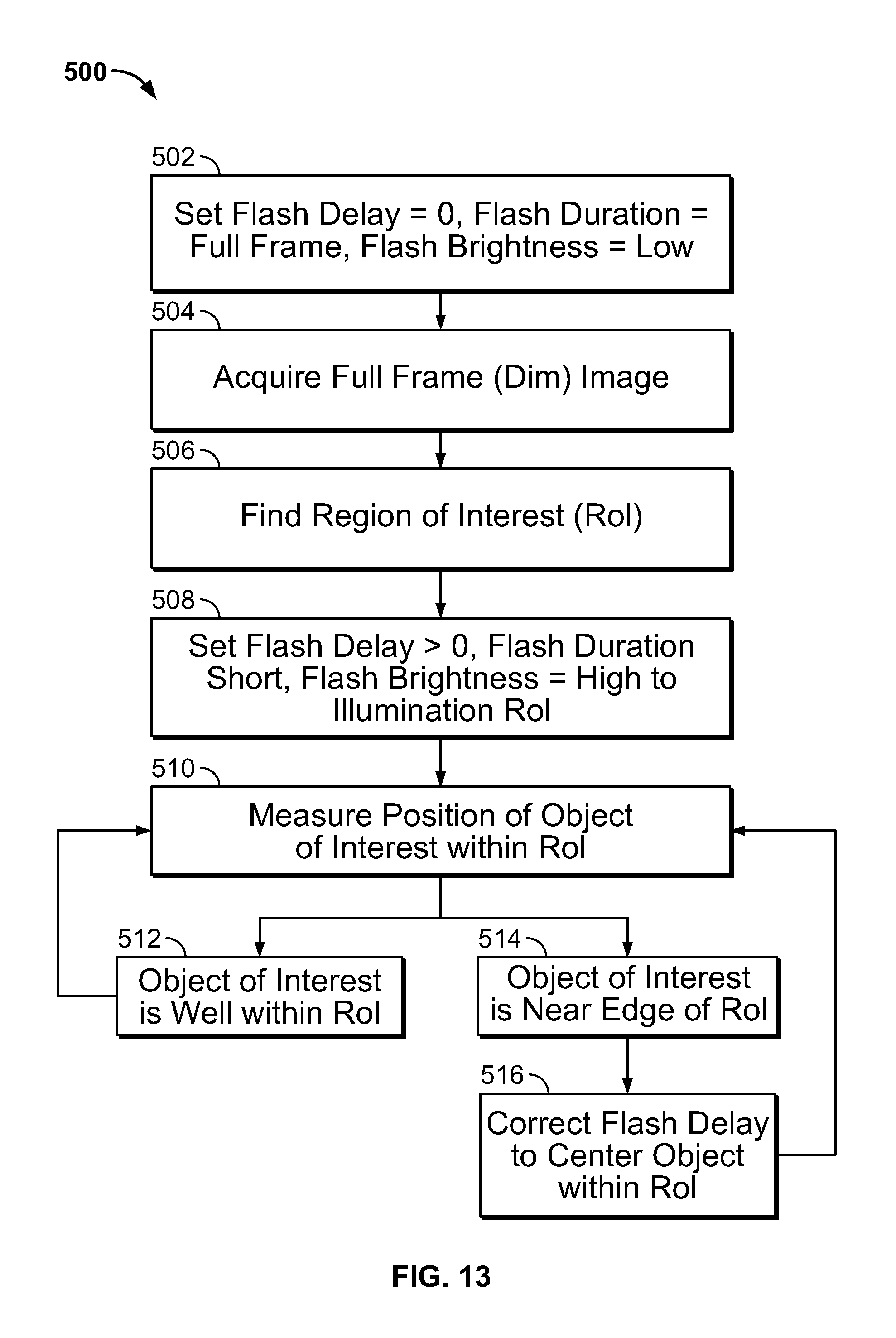
FIG. 13 is a flowchart illustrating an exemplary process of implementing an exemplary biometric analysis system in accordance with the present disclosure.
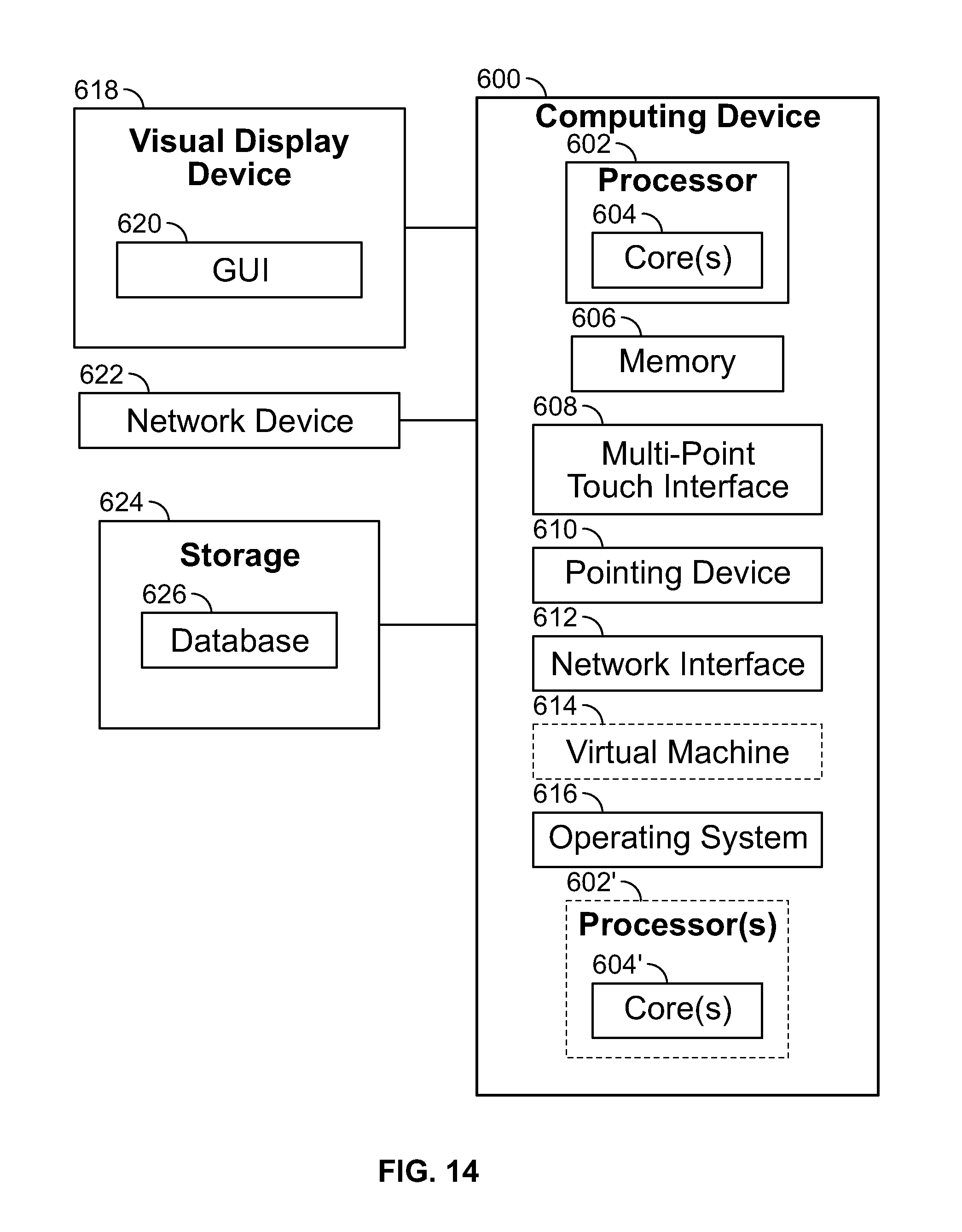
FIG. 14 is a block diagram of an exemplary computing device for implementing an exemplary biometric analysis system in accordance with the present disclosure.
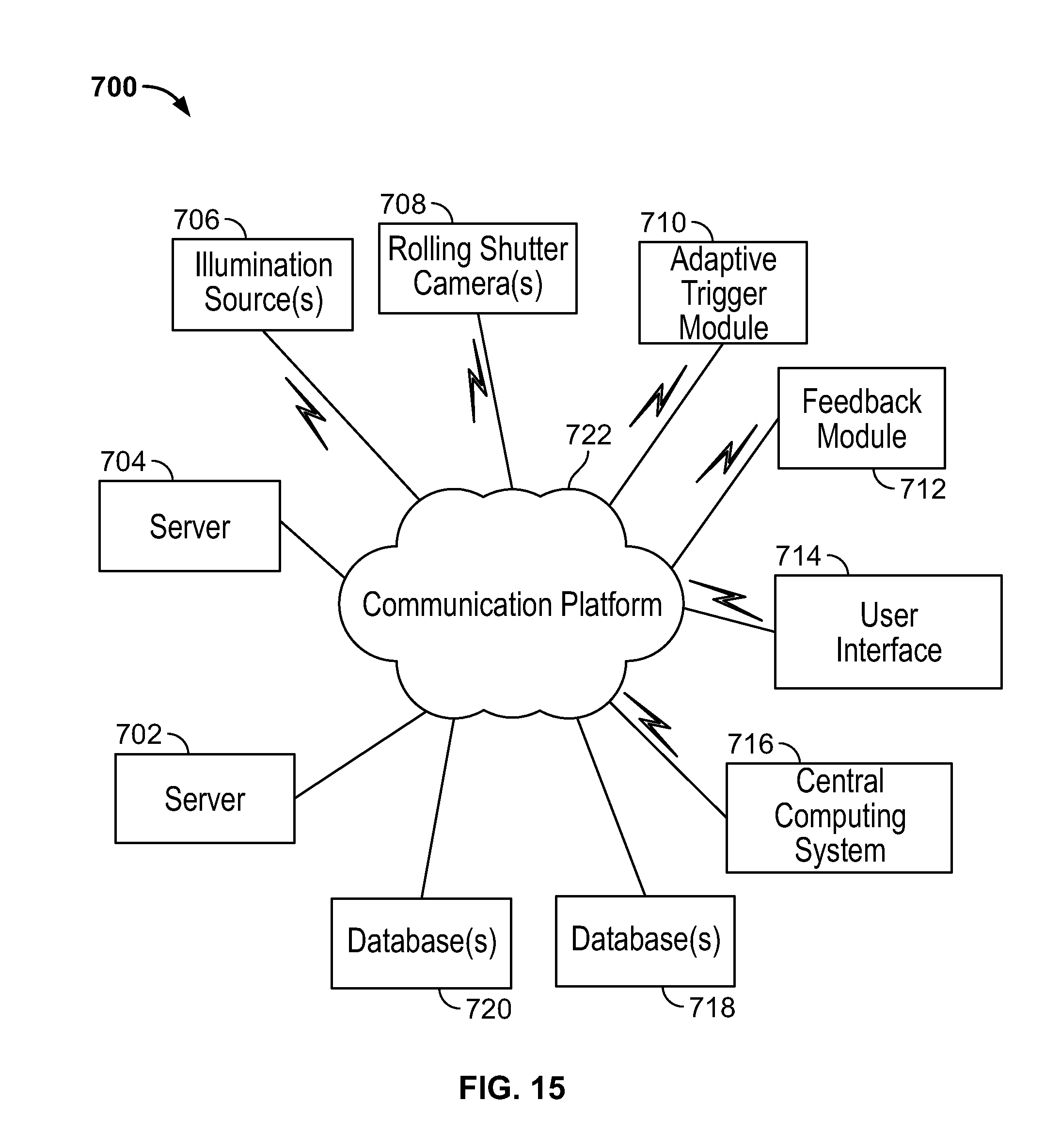
FIG. 15 is a block diagram of an exemplary biometric analysis system environment in accordance with the present disclosure.
DESCRIPTION OF EXEMPLARY EMBODIMENTS
In accordance with embodiments of the present disclosure, exemplary biometric analysis systems are described herein for a rolling shutter camera that include an adaptive trigger for ensuring that the stripe of light from the flash illumination illuminates a region of interest of an object, such as the eyes of a person, during image writing. The biometric analysis systems generally include one or more illumination sources that initially provide dim illumination to a scene to detect the object and identify the region of interest of the object. Based on the identified region of interest, a delay between the start of image writing by the rolling shutter camera and the trigger of the illumination source is arranged or coordinated to ensure that the stripe of the flash illumination coincides with the region of interest of the object.
Cameras that include rolling shutter image sensors are typically cheaper than those with global shutter image sensors. The exemplary biometric analysis systems use flash illumination in combination with inexpensive rolling shutter cameras of the type found in low-cost cameras and smartphones. The biometric analysis systems address a rolling shutter-specific problem that occurs when the brightness of the ambient light in the scene may need an exposure time less than the full frame time to avoid saturation, and the exposure time is sufficiently short that the first rows of the image are finished integrating light and reading out before the last lines of the image have begun integration. In cases of short exposure times, a single, short flash pulse will not illuminate an entire frame, leaving portions of the frame relatively dark. Long exposure times can result in motion blur.
The exemplary biometric analysis systems balance the following parameters to ensure the captured image quality is sufficient for identification, and further ensuring that the region of interest is adequately illuminated by the flash: sensor frame rate, sensor exposure time, flash pulse intensity, flash pulse duration, flash pulse repetition, processed frame rate, and flash pulse offset. Increasing the sensor frame rate over the available ranges increases the speed that the reset and read lines move over the image. For a given sensor exposure time, increasing the frame rate effectively increases the number of exposed lines during that period. For example, with the exposure time remaining the same, the execution time of the internal clock of the camera can be increased to operate the camera at a faster rate, thereby capturing a greater number of lines during the exposure time. The drawbacks of increased sensor frame rates are additional data transfers and additional heating due to higher clock speed. Lower frame rates may be desirable for dark indoor lighting conditions and higher frame rates may be desirable for outdoor bright lighting conditions.
Increasing the sensor exposure time increases the distance between the reset and read times. This effectively increases the number of exposed lines during that period, allowing a short flash pulse to cover more lines. The drawback of increasing this period is that additional ambient light is accumulated over the entire period. During outdoor operation, it may be beneficial to keep the exposure time as short as possible, but allowing enough lines to be covered by the flash. Keeping the exposure time shorter is also important to avoid introducing motion blur which can degrade recognition performance.
The flash pulse needs to be bright enough to overpower direct sunlight for effective outdoor operation. The flash pulse is limited by available system power and eye safety limits. In general, eye safety can be roughly proportional to the total amount of energy absorbed by the eye over a period of time (e.g., t.sup.-0.75). Reducing the intensity, pulse duration, and pulse repetition all move the system into a safer standing. Longer flash pulses allow more lines to be exposed in a rolling shutter. However, longer pulses can lead to increased eye safety concerns forcing the system to use less intense pulses when longer durations are used.
Several short flash pulses may be used back-to-back to illuminate additional lines with minimal overlap between exposed lines. This technique can reduce the total eye exposure and power requirements while expanding the total number of lines that can be properly illuminated. Pulse rate, duration, and intensity can all impact the system power requirements. Increasing any of these parameters generally increases the demand for power.
In some embodiments, since eye safety depends on the total exposure over a period of time, one method to reduce the total exposure can be to selectively process frames. While images can be captured at 60 frames per second (fps), only one in four can be illuminated with the flash, which would reduce the exposure to an equivalent of 15 fps with the advantages of capturing at 60 fps. Such technique allows for improved line read speeds, bringing the rolling shutter camera closer to the global shutter camera timing.
In some embodiments, the systems can include a continuous feedback loop to a user who is attempting to align their eye with a small box on the screen (e.g., in situations involving a smaller screen, such as a smartphone). The feedback loop allows the system to predetermine which lines should be exposed. A low level of continuous, dim illumination can be provided to ensure the user has a reasonable image to complete this task. Depending on the available processing power and flash offset controls, the continuously illuminated frames can be processed to detect specular reflections, and further used to change the flash offset or delay. Such operation allows the user additional margin when attempting to place their eye in the box while keeping the exposure levels to a minimum.
The biometric analysis systems adjust the portion of the frame that is illuminated such that the important portion of the image (e.g., a region of interest) is well-lit and the unimportant portions of the images are left dim. The biometric analysis systems can be used in imaging in the near infrared (NIR) spectrum using a short, intense, eye-safe NIR flash with an NIR filter to freeze motion and emphasize the flash relative to ambient light (including bright sun). The biometric analysis systems including the NIR flash with a rolling shutter camera can be used in, e.g., iris biometrics, or the like, in which cost reduction realized by using a rolling shutter instead of a global shutter is a primary driver in component selection.
The biometric analysis systems include an adaptive step in which dim illumination allows a vision system (e.g., a sensor in a rolling shutter camera including a processor) to detect the position of the desired object in the field-of-view of the camera. In some embodiments, the dim illumination remains on for the entire process of capturing an image, and reveals an under-illuminated frame. Dim illumination, although dimmer than illumination by the flash, is bright enough to perform an automated scene analysis, e.g., face finding, object identification, or the like, that can output a recommendation of a position in the frame that would benefit from flash illumination. For example, if a face appeared between 20% and 40% of the frame height measured from the bottom, a controller or processor can arrange a delay between the start of image writing and the flash trigger such that a stripe of illumination coincides with the desired object. If the object moves in the field-of-view, biometric analysis systems can function dynamically to track movement of the object and change the delay accordingly. In some embodiments, rather than or in addition to using dim illumination, the adaptive trigger module can be executed to search and find the region of interest by systematically sweeping an illuminated stripe down the field-of-view and stopped when a region of interest is detected. Thus, rather than using a single frame (as in dim illumination), the illuminated stripe can be a fraction in width of the full frame and is advanced across the field-of-view, thereby using multiple frames to detect the region of interest. The region of interest can be tracked by the adaptive trigger module after being detected. Such arrangements to locate and track the object and indicate to the adaptive trigger module changes in the position of the object permits moving objects to be accurately imaged by the biometric analysis systems.
The biometric analysis systems disclosed herein can be used for rolling shutter photography (e.g., NIR photography) of objects while outdoors or indoors. The biometric analysis systems can acquire NIR images with controlled illumination in full sun or in dim ambient lighting. An image of a desired object that fills less than a full frame, e.g., a person's face with the entire person in the field-of-view, can be captured by the biometric analysis systems. Due to the low cost, small size and availability of rolling shutter sensors, incorporation of the biometric analysis systems into cost-sensitive or size-sensitive platforms can benefit cost-sensitive or size-sensitive users. As one example, the biometric analysis systems can be used in cargo identification in which infrared dye for markings signify authenticity. As another example, a box marked with writing can be imaged with a small and inexpensive handheld infrared camera that would look for the marking surrounding an NIR watermark.
The flash trigger can be adjusted to fire in order to illuminate the markings, leaving the rest of the field-of-view above and below the mark of interest in the dark. Handheld devices, including smartphones, barcode readers, and other mass produced electronic devices, can incorporate the biometric analysis systems at a small and low cost. Traditionally, a rolling shutter camera would reduce the cost for such systems, but would require an extended flash to illuminate an entire scene to guarantee capturing the subject of interest. The exemplary biometric analysis systems include a rolling shutter camera with an adaptive image content-based trigger that issues a shorter flash of a near infrared light that allows for use of smaller batteries, provides for a longer battery life, provides for improved eye safety, and allows for longer illumination source lifetimes.
The biometric analysis systems disclosed herein can provide flash illumination for illuminating an object sufficiently to outshine the sun, and in some embodiments can use strobing flash illumination as is disclosed in, e.g., U.S. Pat. No. 7,542,628; 7,627,147; 7,657,127; 9,131,141; U.S. Patent Application Publication No. 2015/0098630; U.S. Patent Application Publication No. 2016/0014121; U.S. Patent Application Publication No. 2016/0012218; and U.S. Patent Application Publication No. 2016/0012292, which are incorporated by reference herein.
The exemplary biometric analysis systems use a rolling shutter camera and a flash illumination that is triggered adaptively to illuminate the region of interest of the scene or object. The adaptive trigger can be configured to follow or track the subject, and adjusts the flash timing to maintain the stripe of flash illumination on the subject of interest. In one embodiment, a face finder can be used as an image analytic to trigger the flash. In one embodiment, a unique identifier, such as a bar code or QR code, can be detected and illuminated by the stripe of flash illumination. In either case, the biometric analysis system can locate the object in a relatively dimly lit scene, and then initiates the repetitive flash that illuminates the object. Flash timing can be adjusted to maintain the object in the illuminated region of the field-of-view of the rolling shutter camera.
With respect to the delayed flash, an assumption can be made that the start of integration of the first row of a rolling shutter sensor coincides with time t=0. A further assumption can be made that a flash pulse is started at some time later, e.g., delayed by a time .DELTA.t. Rows that are read-out (e.g., integrate light) before .DELTA.t miss any light from the flash. Rows that are in the process of integrating light when the flash starts--some nearly finished, some just starting--receive fractions of the flash and form the ramp-up region of partial illumination. Pixels in rows that start integrating at or after the start of the flash and that finish integrating light by the end of the flash are illuminated by the full flash. By adjusting the delay time .DELTA.t, the rows of full flash illumination can be adjusted from the top of the image frame to the bottom to focus on a region of interest located within the frame.
In particular, the biometric analysis systems can be used to detect the region of interest within the frame of the rolling shutter camera, and intentionally delay the flash illumination in a coordinated manner to ensure that the region of interest is illuminated by the flash during exposure and read-out of the corresponding rows. Proper adjustment of the delay time can cause the stripe of flash illumination due to the short flash pulse to brighten the region of interest. In some embodiments, the stripe can scan or search the image in successive frames of a photo or video stream. Such technique can be performed by systematically sweeping an illuminated stripe down the field-of-view and stopping when a region of interest is detected. Thus, rather than using a single frame (as in dim illumination), the illuminated stripe can be a fraction in width of the full frame and is advanced across the field-of-view, thereby using multiple frames to detect the region of interest. The region of interest can be tracked by the adaptive trigger module after being detected.
In some embodiments, a pre-flash (e.g., a single long, low intensity flash that illuminates the full frame and that is both eye-safe and within the operating range of the illumination hardware) can provide a single, dim image of the scene. Automated image analysis of the full scene that can tolerate the low light can detect and output a region of interest that is the width of the image and the height of the flash illumination stripe. With the region of interest defined, an automated delay signal can set the illumination stripe to the optimal position to illuminate the region of interest in succeeding frames of a photo or video stream using the full flash brightness over the narrowed region of interest. If the desired feature of the object begins to move out of the illumination stripe (as determined by video analysis performed at the frame rate), the delay can adapt using negative feedback to maintain the position of the desired feature centered within the well-lit region of the image.
In some embodiments, the biometric analysis systems can be used to capture NIR images of an object that is bathed in sunlight. While a fraction of the solar spectrum covers the NIR wavelengths, it can be assumed that filtered solar NIR irradiance (e.g., from 800 nm to 900 nm) is insufficient to illuminate a video frame that is adequately short in duration to suppress motion blur. It can be further assumed that using a long flash that covers the entire rolling shutter frame period is impractical, even with a short exposure time, due to hardware limitations or eye safety concerns. A short NIR flash pulse that can only illuminate a portion of the frame with an adaptive delay time to ensure that the region of interest is illuminated can therefore be used.
The biometric analysis systems initially detect and identify a region of interest of an object, such as the eyes of a subject. Eye finding can be accomplished using a number of different processes, such as full frame NIR illumination with a relatively dim, eye-safe (and hardware-safe) long NIR flash pulse; partial frame illumination due to a short, intense pulse that is automatically swept frame-by-frame over the full field-of-view until the eyes appear in the search; and/or image acquisition by a color (or other spectrum) auxiliary camera that produces a full frame image allowing eye-finding or face-finding, and then translation from the auxiliary camera frame position to a NIR camera position.
After the eyes are detected and their position located in the NIR camera frame, the biometric analysis systems automatically set the flash pulse delay to illuminate a stripe across the frame including the eyes (e.g., the region of interest). The delay that sets the vertical position of the illumination stripe can be automatically adjusted to maintain the eyes in substantially the center of the frame. While the portions of the frame outside of the illumination stripe remain unusably dark, the important information about the eyes remains well lit.
The competing solar illumination may dimly illuminate the rest of the frame. This is not an issue as long as the flash illumination stripe remains resolved and does not saturate due to the sum of the in-band solar irradiance and the applied NIR light. If the illumination stripe nears the saturation level, the intensity of the applied flash can be throttled back. It is preferable to decrease the NIR illumination irradiance on the object rather than reducing the exposure or pulse duration, since the later strategies reduce the portions of the image that are illuminated.
Any spectrum of light can be used as long as the camera uses a rolling shutter with an in-band flash illuminator. For example, visible light, NIR, short-wave infrared (SWIR), long-wave infrared (LWIR), ultraviolet (UV), or multi-spectral cameras with rolling shutters that use flash illumination. Any process of finding the region of interest can be used as long as the process returns a coordinate to the biometric analysis system that indicates the time delay between the start of frame and the start of the flash. For example, use of an eye finder that seeks corneal reflections of the flash could be useful if the region of interest contains one or two eyes of the subject. As a further example, a color face camera could be useful to find the eyes of a subject in iris recognition; but if nose-recognition were used, the region of interest would contain the subject's nose. If the same camera were used to find the region of interest and to acquire the information from the region of interest, a different illumination protocol could be used for each function. For example, a long, relatively dim pulse could illuminate the entire frame, followed by a short, bright pulse to illuminate the region of interest with better fidelity (e.g., improved signal-to-noise ratio). Any process that provides the information needed to set the delay time would also be useful.
In some embodiments, feedback can be used to maintain the region of interest in the illumination stripe. For example, negative feedback can be used to correct the position of the region of interest within the illumination stripe. If the object of interest begins to move or slip to the top or bottom of the region of interest illuminated by the flash, feedback can be used to correct the delay time. For example, if the stripe illuminating the region of interest needs to move up in the frame to follow the object of interest, the delay would need to be corrected in one direction. If the object of interest moves down in the frame, the sign of the delay correction would need to be in the opposite direction. If the delay reaches the minimum or maximum value or, in other words, the object of interest begins to leave the camera field-of-view, the controller or processing device automatically reorients the camera to maintain the object in the field-of-view. In some embodiments, a feedback signal (e.g., an audio alarm, a visual alarm, combinations thereof, or the like) can provide feedback to an operator regarding the object leaving the field-of-view.
The width of the flash illumination stripe relative to the frame height can be set by practical considerations. For example, rolling shutter cameras with very short read-out times generally have wider flash illumination stripes, all other things being equal. The longest flash pulse can be dictated by practical issues, including available power to the illumination source, operating conditions in power, and temperature of the illumination source. For example, it is known that flashing an illumination source too often can damage it, and reduces the safety of human eyes in and around the illumination source. A flash illumination stripe that is narrow relative to the frame height generally should be more accurately timed than a flash illumination stripe that is wider and that can tolerate more motion of the object of interest within the flash illumination stripe.
With reference to FIG. 8, a schematic block diagram of an exemplary biometric analysis system 100 (hereinafter "system 100") is provided. The system 100 is configured to detect and identify a region of interest of an object, such as the eyes of a person, and generates a time delay of the flash illumination such that the flash coincides with the region of interest. A rolling shutter camera can therefore be used for capturing one or more images for biometric analysis with the delayed flash illumination ensuring that the region of interest will be properly illuminated in the captured images. The system 100 is configured to track the region of interest within the frame or field-of-view of the rolling shutter camera, and adjusts the time delay of the flash pulse appropriately based on movement of the region of interest in and out of the frame.
The system 100 generally includes one or more illumination sources 102. The illumination sources 102 are configured to initially provide dim illumination 104 to a scene including an object to detect and identify the object (or the region of interest of the object). In some embodiments, the dim illumination 104 can be separate from the system 100 and can be provided by, e.g., ambient light, any other illumination source, sunlight, combinations thereof, or the like. The illumination sources 102 are further configured to provide flash illumination 106 (e.g., a pulse of flash illumination) to illuminate the region of interest during exposure of the rows corresponding to the region of interest, thereby ensuring that the region of interest will be illuminated in the captured image. In some embodiments, a single illumination source 102 can provide both the dim illumination 104 and the flash illumination 106. In some embodiments, separate illumination sources 102 can provide the dim illumination 104 and the flash illumination 106. In one embodiment, the illumination sources 102 can be NIR illumination sources. It should be understood that the dim illumination 104 is less bright than the flash illumination 106, and provides sufficient ambient light for the system 100 to detect objects in a scene as viewed by the rolling shutter camera.
The system 100 includes a rolling shutter camera 108 including a frame 110 with a field-of-view. The rolling shutter camera 108 is configured to capture one or more images (e.g., still frame images, video images, combinations thereof, or the like). The rolling shutter camera 108 is configured to initially capture an image of the scene and the object in the scene under dim illumination 104 conditions. The system 100 includes an adaptive trigger module 112 configured to be executed by a processing device 114 having a processor 116 (e.g., a controller). Although illustrated as separate components from the rolling shutter camera 108, it should be understood that in some embodiments, the rolling shutter camera 108 can include the illumination sources 102, the adaptive trigger module 112, the processing device 114, or the like. In some embodiments, the processing device 114 can be part of a central computing system 118. When executed, the adaptive trigger module 112 can analyze the captured image of the scene illuminated by the dim illumination 104 and detects the region of interest 120 within the scene. For example, the adaptive trigger module 112 can detect and identify the region of interest 120 as one of more eyes of the user, and stores the rows of the frame 110 corresponding to the region of interest 120 in a database 122 (e.g., a local or remote database).
Based on the rows of the frame 110 corresponding to the region of interest 120, the adaptive trigger module 112 arranges a flash pulse delay 124 between the start of image writing by the rolling shutter camera 108 and a trigger of the flash illumination 106 such that the flash illumination 108 coincides with the identified region of interest 120. For example, if the eyes of the user are the region of interest 120 corresponding with rows 400-600 of the frame 110, the adaptive trigger module 112 arranges the flash pulse delay 124 such that the flash illumination 106 is triggered to illuminate the object during rows 400-600. Thus, rather than triggering the flash illumination 106 at the same time as the start of image writing by the rolling shutter camera 108, the image writing can start before triggering of the flash illumination 106 and the flash illumination 106 is only triggered to illuminate the region of interest 120. Such flash delay 124 ensures that the region of interest 120 is illuminated in the images 126 captured by the rolling shutter camera 108. The resulting image 126 generally includes a stripe of flash illumination 106 extending across the image 126 and over the eyes of the user (see, e.g., FIG. 9). Depending on the length of the exposure time, the height of the stripe of flash illumination 106 can be greater or smaller relative to the top and bottom of the image 126.
In some embodiments, the adaptive trigger module 112 can include a face finder algorithm that locates the face and/or features of the face in the scene. The face finder algorithm can therefore locate the face identifies one or more eyes of the face as the region of interest 120. Although discussed herein as eyes of a user, it should be understood that the region of interest 120 can be a unique identifier associated with a physical item that can be detected by an identifier finder algorithm of the adaptive trigger module 112. For example, the identifier finder algorithm of the adaptive trigger module 112 can be used to detect, e.g., a barcode, a QR code, or the like, on a physical item, identifies such unique identifier as the region of interest 120, and adjusts the flash delay 124 to ensure that the unique identifier is illuminated during capture of the image 126.
The adaptive trigger module 112 can be configured to track movement of the object within the field-of-view or frame 110 of the rolling shutter camera 108. In some embodiments, the adaptive trigger module 112 can be configured to continuously scan the scene in the frame 110 to detect the position of the region of interest 120. If the user moves such that the region of interest 120 in the frame 110 is not centered or changes relative to the previously detected rows for the region of interest 120, the adaptive trigger module 112 can determine the new rows corresponding to the region of interest 120, stores the new rows in the database 122, and adjusts the flash delay 124 to coincide with the new rows for the region of interest 120. Thus, an object moving in the frame 110 of the rolling shutter camera 108 can be tracked by the adaptive trigger module 112 to allow for the region of interest 120 of a moving object to be properly illuminated by the flash illumination 106.
The system 100 includes a feedback module 128 configured to be executed by the processing device 114 and/or the central computing system 118. In some embodiments, the rolling shutter camera 108 can include the feedback module 128. When executed, the feedback module 128 receives as input the images 126 captured by the rolling shutter camera 108 and analyzes the region of interest 120 captured in the image 126 to determine if the region of interest 120 is illuminated by the stripe of flash illumination 106. If the region of interest 120 is illuminated by the stripe of flash illumination 106, the feedback module 128 electronically outputs such findings to the adaptive trigger module 112 and no changes are made in the flash delay 124. If the region of interest 120 is not illuminated (or only partially illuminated) by the stripe of flash illumination 106, the feedback module 128 electronically outputs such findings to the adaptive trigger module 112. Based on the feedback from the feedback module 128, the adaptive trigger module 112 analyzes the frame 110 to locate the region of interest 120, determines the new rows associated with the region of interest 120, and adjusts the flash pulse delay 124 to trigger the flash illumination 106 at the appropriate rows coinciding with the region of interest 120. The feedback loop can be continuously performed to ensure the region of interest 120 is always illuminated by the stripe of flash illumination 106.
The system 100 can include a user interface 130 with a graphical user interface (GUI) 132 for receiving input from a user and for outputting information to the user. For example, the user interface 130 can be used to initiate the process performed by the system 100. As a further example, the user interface 130 can output an audio and/or visual alarm to the user when the region of interest 120 is no longer centered in the frame 110. The system 100 can include a communication interface 134 configured to provide a means for electronic transmission between components of the system 100, e.g., the illumination sources 102, the processing device 114, the rolling shutter camera 108, the adaptive trigger module 112, the database 122, the user interface 130, the central computing system 118, and feedback module 128, or the like.
FIG. 10 is a diagrammatic view of an exemplary biometric analysis system 200 (hereinafter "system 200") of the present disclosure. The system 200 includes an illumination source 202 that provides dim illumination to the subject 204 in the scene. In some embodiments, the illumination source 202 can provide 1 ms NIR pulses to the scene. In some embodiments, the illumination source 202 can be an NIR light source not connected to the camera 208. The illumination source 202 can be positioned a distance 206 from the subject 204. In some embodiments, the illumination source 202 can also be configured to provide the flash illumination to the subject 204.
The system 200 includes a camera 208 including a rolling shutter (e.g., a rolling shutter camera, such as a smartphone camera, or the like) configured to capture one or more images of the subject. The camera 208 can have a field-of-view represented by area 216, including the region of interest of the subject 204. In some embodiments, the camera 208 includes an illumination source 210 (e.g., an integrated NIR light source) configured to provide flash illumination to a region of interest (e.g., the eyes of the subject 204). As an example, area 212 indicates the coverage of the NIR flash illumination provided by the illumination source 210, with the region of interest on the subject 204 being within the area 212. The camera 208 can be spaced by a distance 214 from the subject 204. In FIG. 10, the illumination source 202 appears separate from camera 202, however, one skilled in the art shall appreciate that, in some embodiments, the illumination source 202 can be incorporated into the camera 208 assembly such that the camera 208 assembly is capable of providing both the dim illumination and flash illumination to the subject 204.
FIG. 11 is a diagrammatic view of a frame action 300 of a rolling shutter camera of the exemplary biometric analysis systems disclosed herein. The frame action 300 includes a total frame time 302. Ambient light 304 having a low illumination level 306 can be provided for all or part of the total frame time 302 by a dim illumination source and/or sunlight. The total camera exposure time 308 indicates when the rolling shutter camera begins and ends image writing and read-out.
Based on the determination of the region of interest and the corresponding rows of the frame, a pulse of flash illumination 310 (e.g., NIR from a light-emitting diode (LED) illumination source) is triggered to coincide with the rows of the region of interest. The pulse of flash illumination 310 has a time or pulse width 312 that is significantly smaller than the camera exposure time 308, and an illumination level 314 that is brighter or higher than the level 306 of the ambient light 304. The region of interest is thereby illuminated by the flash illumination 310 while the remaining rows of the captured image are only illuminated by the ambient light 304.
In some embodiments, a 1280.times.960 sensor can be used with the rolling shutter camera. In some embodiments, a 120 fps VGA (640.times.480) sensor can be used with the rolling shutter camera to allow for full frame exposure in 4 ms, and can be synchronized with an approximately 4 ms LED flash every 8.sup.th frame. The VGA output can provide (unscaled) 15 fps feedback to the user facing the monitor of the system. The 4 ms can provide sufficient flash pulse while allowing for cost effective use of an LED and rolling shutter accommodation, and allowing for eye safety.
In some embodiments, a bright light (e.g., approximately 850 nm LED, two LEDs) can be used for the flash pulse. The systems can therefore have high pulsed current capabilities. The rolling shutter camera can have a high quality camera lens and NIR filtering. In some embodiments, the NIR filter can be tighter than 100 nm around the LED center wavelength. In some embodiments, the system can include optics with a modulation transfer function (MTF) optimized for the spatial frequencies that enter the system. In some embodiments, the system can include preprocessing of iris images for a particular spectrum of spatial frequencies (e.g., low, medium, high, or the like).
FIG. 12 is a flowchart illustrating an exemplary process 400 of implementing the biometric analysis systems disclosed herein. To begin, at step 402, a scene and an object in the scene are illuminated with dim illumination from one or more illumination sources. At step 404, the scene is analyzed with an adaptive trigger module to detect the object (or a region of interest associated with the object) in the scene during dim illumination. At step 406, a position in a frame of a rolling shutter camera is determined with the adaptive trigger module, the position coinciding with the detected object (or region of interest associated with the object) in the scene.
At step 408, a delay is arranged by the adaptive trigger module between a start of image writing by the rolling shutter camera and a trigger of the illumination sources such that a stripe of flash illumination provided by the illumination sources coincides with the detected object (or region of interest associated with the object) in the scene. At step 410, movement of the object is tracked within a field-of-view of the rolling shutter camera with the adaptive trigger module. At step 412, the delay between the start of image writing by the rolling shutter camera and the trigger of the illumination sources is modified with the adaptive trigger module based on detected movement of the object (or region of interest associated with the object) out of the field-of-view.
FIG. 13 is a flowchart illustrating an exemplary process 500 of implementing the biometric analysis systems disclosed herein. To begin, at step 502, the adaptive trigger module can set the flash delay at 0 ms, the flash duration equal to the time of the full frame, and the flash brightness to low. At step 504, a full frame image can be acquired with the rolling shutter camera under dim illumination. At step 506, the adaptive trigger module analyzes the image captured at step 504 and locates the region of interest in the image.
At step 508, the adaptive trigger module sets the flash delay to a value greater than 0 ms, the flash duration to short (e.g., a pulse), and the flash brightness to high (e.g., higher than the dim illumination) to illuminate the region of interest. At step 510, the adaptive trigger module measures the position of the object of interest within the region of interest (e.g., eyes of the user located on the user's face). At step 512, if the object of interest is within the region of interest, the process 500 continues a loop to constantly (or at predetermined frequencies of time) ensure that the object is maintained within the region of interest. At step 514, if the object of interest is near an edge of the frame or region of interest, the process 500 performs step 516 to correct the flash delay such that the object is centered within the region of interest. The region of interest can thereby be maintained in the flash illumination stripe despite relative motion of the object and/or the camera. In some embodiments, the process can include a loop that analyzes the captures images to control the intensity of the flash illumination, thereby avoiding saturation of the object.
FIG. 14 is a block diagram of a computing device 600 in accordance with exemplary embodiments of the present disclosure. The computing device 600 includes one or more non-transitory computer-readable media for storing one or more computer-executable instructions or software for implementing exemplary embodiments. The non-transitory computer-readable media may include, but are not limited to, one or more types of hardware memory, non-transitory tangible media (for example, one or more magnetic storage disks, one or more optical disks, one or more flash drives), and the like. For example, memory 606 included in the computing device 600 may store computer-readable and computer-executable instructions or software for implementing exemplary embodiments of the present disclosure (e.g., instructions for operating the illumination sources, instructions for operating the processing device, instructions for operating the rolling shutter camera, instructions for operating the adaptive trigger module, instructions for operating the communication interface, instructions for operating the user interface, instructions for operating the central computing system, instructions for operating the feedback module, combinations thereof, or the like). The computing device 600 also includes configurable and/or programmable processor 602 and associated core 604, and optionally, one or more additional configurable and/or programmable processor(s) 602' and associated core(s) 604' (for example, in the case of computer systems having multiple processors/cores), for executing computer-readable and computer-executable instructions or software stored in the memory 606 and other programs for controlling system hardware. Processor 602 and processor(s) 602' may each be a single core processor or multiple core (604 and 604') processor.
Virtualization may be employed in the computing device 600 so that infrastructure and resources in the computing device 600 may be shared dynamically. A virtual machine 614 may be provided to handle a process running on multiple processors so that the process appears to be using only one computing resource rather than multiple computing resources. Multiple virtual machines may also be used with one processor. Memory 606 may include a computer system memory or random access memory, such as DRAM, SRAM, EDO RAM, and the like. Memory 606 may include other types of memory as well, or combinations thereof.
A user may interact with the computing device 600 through a visual display device 618 (e.g., a personal computer, a mobile smart device, or the like), such as a computer monitor, which may display one or more user interfaces 620 (e.g., a graphical user interface) that may be provided in accordance with exemplary embodiments. The computing device 600 may include other I/O devices for receiving input from a user, for example, a camera, a sensor, a keyboard or any suitable multi-point touch interface 608, a pointing device 610 (e.g., a mouse). The keyboard 608 and the pointing device 610 may be coupled to the visual display device 618. The computing device 600 may include other suitable conventional I/O peripherals.
The computing device 600 may also include one or more storage devices 624, such as a hard-drive, CD-ROM, eMMC (MultiMediaCard), SD (secure digital) card, flash drive, non-volatile storage media, or other computer readable media, for storing data and computer-readable instructions and/or software that implement exemplary embodiments of the biometric analysis systems described herein. Exemplary storage device 624 may also store one or more databases 626 for storing any suitable information required to implement exemplary embodiments. For example, exemplary storage device 624 can store one or more databases 626 for storing information, such as data relating to captured images 126 under dim illumination 104 and flash illumination 106, regions of interest 120, flash delay 124, combinations thereof, or the like, and computer-readable instructions and/or software that implement exemplary embodiments described herein. The databases 626 may be updated by manually or automatically at any suitable time to add, delete, and/or update one or more items in the databases.
The computing device 600 can include a network interface 612 configured to interface via one or more network devices 622 with one or more networks, for example, Local Area Network (LAN), Wide Area Network (WAN) or the Internet through a variety of connections including, but not limited to, standard telephone lines, LAN or WAN links (for example, 802.11, T1, T3, 56 kb, X.25), broadband connections (for example, ISDN, Frame Relay, ATM), wireless connections, controller area network (CAN), or some combination of any or all of the above. The network interface 612 may include a built-in network adapter, network interface card, PCMCIA network card, PCI/PCIe network adapter, SD adapter, Bluetooth adapter, card bus network adapter, wireless network adapter, USB network adapter, modem or any other device suitable for interfacing the computing device 600 to any type of network capable of communication and performing the operations described herein. Moreover, the computing device 600 may be any computer system, such as a workstation, desktop computer, server, laptop, handheld computer, tablet computer (e.g., the tablet computer), mobile computing or communication device (e.g., the smart phone communication device), an embedded computing platform, or other form of computing or telecommunications device that is capable of communication and that has sufficient processor power and memory capacity to perform the operations described herein.
The computing device 600 may run any operating system 616, such as any of the versions of the Microsoft.RTM. Windows.RTM. operating systems, the different releases of the Unix and Linux operating systems, any version of the MacOS.RTM. for Macintosh computers, any embedded operating system, any real-time operating system, any open source operating system, any proprietary operating system, or any other operating system capable of running on the computing device and performing the operations described herein. In exemplary embodiments, the operating system 616 may be run in native mode or emulated mode. In an exemplary embodiment, the operating system 616 may be run on one or more cloud machine instances.
FIG. 15 is a block diagram of an exemplary biometric analysis system environment 700 in accordance with exemplary embodiments of the present disclosure. The environment 700 can include servers 702, 704 configured to be in communication with one or more illumination sources 706, one or more rolling shutter cameras 708, one or more adaptive trigger modules 710, a feedback module 712, a user interface 714, and a central computing system 716 via a communication platform 922, which can be any network over which information can be transmitted between devices communicatively coupled to the network. For example, the communication platform 722 can be the Internet, Intranet, virtual private network (VPN), wide area network (WAN), local area network (LAN), and the like. In some embodiments, the communication platform 722 can be part of a cloud environment.
The environment 700 can include repositories or databases 718, 720, which can be in communication with the servers 702, 904, as well as the one or more illumination sources 706, one or more rolling shutter cameras 708, one or more adaptive trigger modules 710, the feedback module 712, the user interface 714, and the central computing system 716, via the communications platform 722.
In exemplary embodiments, the servers 702, 704, one or more illumination sources 706, one or more rolling shutter cameras 708, one or more adaptive trigger modules 710, the feedback module 712, the user interface 714, and the central computing system 716 can be implemented as computing devices (e.g., computing device 600). Those skilled in the art will recognize that the databases 718, 720 can be incorporated into one or more of the servers 702, 704. In some embodiments, the database 718 can store data relating to captured images, regions of interest 120, flash delay 124, combinations thereof, or the like, can be distributed over multiple databases 718, 720.
While exemplary embodiments have been described herein, it is expressly noted that these embodiments should not be construed as limiting, but rather that additions and modifications to what is expressly described herein also are included within the scope of the invention. Moreover, it is to be understood that the features of the various embodiments described herein are not mutually exclusive and can exist in various combinations and permutations, even if such combinations or permutations are not made express herein, without departing from the spirit and scope of the invention.
* * * * *
References
D00000
D00001
D00002
D00003
D00004
D00005
D00006
D00007
D00008
D00009
D00010
XML
uspto.report is an independent third-party trademark research tool that is not affiliated, endorsed, or sponsored by the United States Patent and Trademark Office (USPTO) or any other governmental organization. The information provided by uspto.report is based on publicly available data at the time of writing and is intended for informational purposes only.
While we strive to provide accurate and up-to-date information, we do not guarantee the accuracy, completeness, reliability, or suitability of the information displayed on this site. The use of this site is at your own risk. Any reliance you place on such information is therefore strictly at your own risk.
All official trademark data, including owner information, should be verified by visiting the official USPTO website at www.uspto.gov. This site is not intended to replace professional legal advice and should not be used as a substitute for consulting with a legal professional who is knowledgeable about trademark law.