Direction-controllable catheter using drug injection channel
Lee , et al.
U.S. patent number 10,363,395 [Application Number 15/563,175] was granted by the patent office on 2019-07-30 for direction-controllable catheter using drug injection channel. This patent grant is currently assigned to KOREA ADVANCED INSTITUTE OF SCIENCE AND TECHNOLOGY. The grantee listed for this patent is Korea Advanced Institute of Science And Technology. Invention is credited to Seong Pil Byeon, Yun Jin Gu, Hye Hyun Han, Ji Hye Hwang, Young Gi Jung, Seung Gyu Kang, Cheong Jun Kim, Myeong Jin Kim, Su Bon Kim, Dong Myoung Lee, Doo Yong Lee, Hyun Seok Lee, Su Hwan Park.


| United States Patent | 10,363,395 |
| Lee , et al. | July 30, 2019 |
Direction-controllable catheter using drug injection channel
Abstract
The present invention relates to a direction-controllable drug injection catheter. According to the present invention, provided is the catheter extending along a central axis "A" including a drug injection part in which a drug injection channel has been formed; a channel opening and closing means which opens and closes the drug injection channel; and a steering structure which is rotationally asymmetric with respect to the central axis "A" and varies according to a pressure change of the drug injection channel for the purpose of steering.
| Inventors: | Lee; Doo Yong (Daejeon, KR), Han; Hye Hyun (Daejeon, KR), Gu; Yun Jin (Daejeon, KR), Kang; Seung Gyu (Daejeon, KR), Kim; Myeong Jin (Daejeon, KR), Kim; Cheong Jun (Daejeon, KR), Byeon; Seong Pil (Daejeon, KR), Jung; Young Gi (Daejeon, KR), Kim; Su Bon (Daejeon, KR), Lee; Hyun Seok (Daejeon, KR), Lee; Dong Myoung (Daejeon, KR), Park; Su Hwan (Daejeon, KR), Hwang; Ji Hye (Daejeon, KR) | ||||||||||
|---|---|---|---|---|---|---|---|---|---|---|---|
| Applicant: |
|
||||||||||
| Assignee: | KOREA ADVANCED INSTITUTE OF SCIENCE
AND TECHNOLOGY (Daejeon, KR) |
||||||||||
| Family ID: | 54061886 | ||||||||||
| Appl. No.: | 15/563,175 | ||||||||||
| Filed: | April 1, 2015 | ||||||||||
| PCT Filed: | April 01, 2015 | ||||||||||
| PCT No.: | PCT/KR2015/003232 | ||||||||||
| 371(c)(1),(2),(4) Date: | September 29, 2017 | ||||||||||
| PCT Pub. No.: | WO2016/159411 | ||||||||||
| PCT Pub. Date: | October 06, 2016 |
Prior Publication Data
| Document Identifier | Publication Date | |
|---|---|---|
| US 20180085556 A1 | Mar 29, 2018 | |
Foreign Application Priority Data
| Mar 31, 2015 [KR] | 10-2015-0045299 | |||
| Current U.S. Class: | 1/1 |
| Current CPC Class: | A61M 25/0075 (20130101); A61M 25/0612 (20130101); A61M 25/0155 (20130101); A61M 25/0084 (20130101); A61M 25/0054 (20130101); A61M 25/0105 (20130101); A61M 25/0138 (20130101); A61M 25/0074 (20130101); A61M 2025/0018 (20130101); A61M 25/0905 (20130101) |
| Current International Class: | A61M 31/00 (20060101); A61M 25/00 (20060101); A61M 25/01 (20060101); A61M 25/06 (20060101); A61M 37/00 (20060101); A61M 25/09 (20060101) |
References Cited [Referenced By]
U.S. Patent Documents
| 5476100 | December 1995 | Galel |
| 6024730 | February 2000 | Pagan |
| 6506196 | January 2003 | Laufer |
| 6746422 | June 2004 | Noriega |
| 2003/0139793 | July 2003 | Hill |
| 2004/0059257 | March 2004 | Gaber |
| 2004/0220470 | November 2004 | Karmarkar |
| 2007/0060997 | March 2007 | de Boer |
| 2007/0100235 | May 2007 | Kennedy, II |
| 2007/0213671 | September 2007 | Hiatt |
| 2015/0088090 | March 2015 | Macy, Jr. |
| 2017/0215694 | August 2017 | Truckai |
Attorney, Agent or Firm: Foley & Lardner LLP
Claims
The invention claimed is:
1. A catheter extending along a central axis "A", the catheter comprising: a drug injection part in which a drug injection channel has been formed; a channel opening and closing means which opens and closes the drug injection channel; and a steering structure which is rotationally asymmetric with respect to the central axis "A" and varies according to a pressure change of the drug injection channel for the purpose of steering.
2. The catheter of claim 1, wherein the steering structure comprises a support which is bonded to one side outer surface of the drug injection part.
3. The catheter of claim 2, wherein the support comprises a base part, and a plurality of bonding portions which protrude from the base part and have ends bonded to the drug injection part.
4. The catheter of claim 3, wherein the plurality of the bonding portions are disposed in a row along an extension direction of the drug injection channel, and wherein a gap is formed between two adjacent bonding portions among the plurality of the bonding portions.
5. The catheter of claim 3, wherein the bonding portion has a shape which becomes narrower toward the end thereof.
6. The catheter of claim 3, wherein in the base part, a plurality of incision portions are formed on the opposite side to the bonding portion, and wherein the incision portion is located corresponding to the gap.
7. The catheter of claim 2, wherein the support is made of a material having a modulus of elasticity greater than that of the drug injection part.
8. The catheter of claim 2, wherein the drug injection channel is eccentrically located with respect to the whole central axis of the catheter, and wherein the support is located on the opposite side to an eccentric direction of the drug injection channel.
9. The catheter of claim 1, wherein the channel opening and closing means comprises a film-shaped fracture portion which is installed on the drug injection channel and is destroyed by a pressure of the drug.
10. The catheter of claim 1, wherein the channel opening and closing means comprises a support wall which is installed on the drug injection channel and has a through-hole formed therein, and an opening and closing member which opens and closes the through-hole, wherein the opening and closing member comprises a cover which is located further downstream than the support wall and opens and closes the through-hole, an elastic support which is located further upstream than the support wall, and an extension rod which passes through the through-hole and connects the cover with the elastic support, wherein the elastic support comprises a plurality of support wings which radially extend outwardly from the extension rod and of which ends contact the support wall.
Description
TECHNICAL FIELD
The present disclosure relates to a catheter and more particularly to a direction-controllable catheter.
BACKGROUND ART
A catheter is a thin and long tube-shaped medical treatment tool. The catheter is inserted into human body and is used to diagnose and cure a disease such as drug injection to a lesion or removal of tumor.
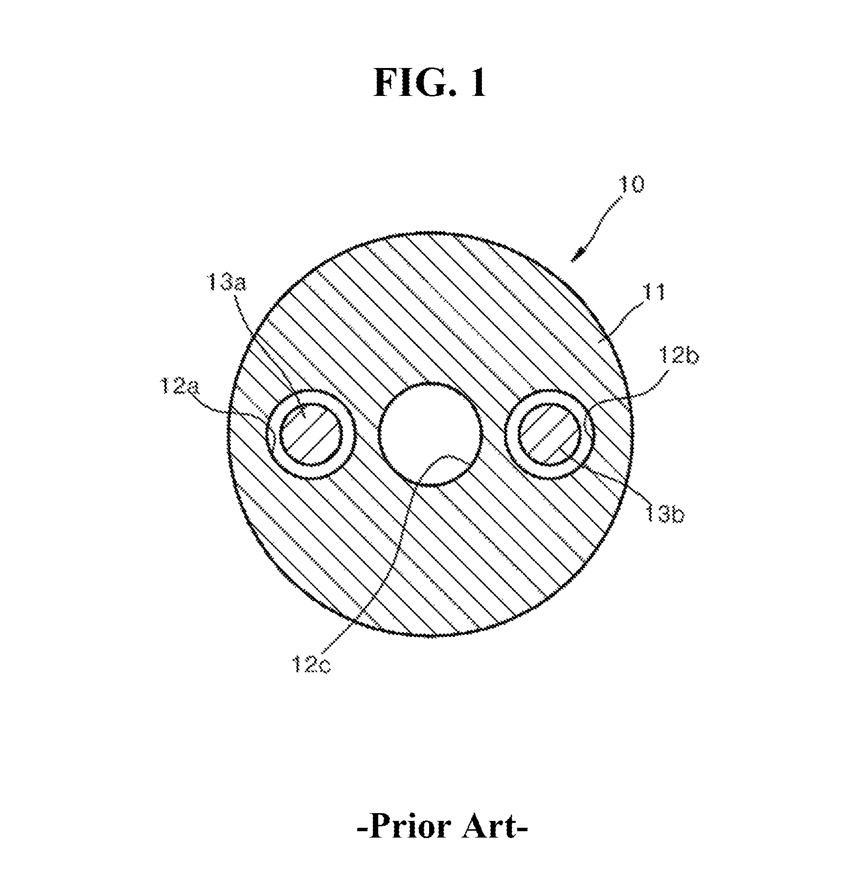
In vascular intervention, after the catheter enters the blood vessel where a lesion exists, the lesion is treated by injecting drugs. If the drug is delivered to a tissue outside the lesion, the tissue outside the lesion necrotizes. Therefore, it is important to position the front end of the catheter as close to the lesion as possible. Accordingly, in a blood vessel with many branches, the catheter capable of steering the front end of the catheter in a desired direction is being developed and used. FIG. 1 is a cross sectional view of a conventional direction-controllable drug injection catheter. Referring to FIG. 1, the catheter 10 includes a flexible tube 11, a drug injection channel 12c formed within the flexible tube 11, two wire channels 12a and 12b formed to have the drug injection channel 12c placed therebetween, and two steering wires 13a and 13b which are positioned in the two wire channels 12a and 12b respectively. The catheter 10 is steered by the two steering wires 13a and 13b. However, in addition to the conventional direction-controllable drug injection channel, two steering channels through which the two steering wires pass respectively are included, so that there is a limit to reduce the thickness of the catheter. Also, the conventional direction-controllable drug injection catheter has a complex structure because it includes a separate configuration for steering.
DISCLOSURE
Technical Problem
The object of the present invention is to significantly reduce the thickness of a direction-controllable drug injection catheter and to simplify the structure of the catheter.
Technical Solution
To achieve the object of the present invention, according to one embodiment of the present invention,
provided is a catheter extending along a central axis "A" including a drug injection part in which a drug injection channel has been formed; a channel opening and closing means which opens and closes the drug injection channel; and a steering structure which is rotationally asymmetric with respect to the central axis "A" and varies according to a pressure change of the drug injection channel for the purpose of steering.
The steering structure may include a support which is bonded to one side outer surface of the drug injection part.
The support may include a base part, and a plurality of bonding portions which protrude from the base part and have ends bonded to the drug injection part.
The plurality of the bonding portions may be disposed in a row along the extension direction of the drug injection channel, and wherein a gap may be formed between two adjacent bonding portions among the plurality of the bonding portions.
The bonding portion may have a shape which becomes narrower toward the end thereof.
In the base part, a plurality of incision portions may be formed on the opposite side to the bonding portion, and the incision portion may be located corresponding to the gap.
The support may be made of a material having a modulus of elasticity greater than that of the drug injection part.
The channel opening and closing means may include a film-shaped fracture portion which is installed on the drug injection channel and is destroyed by a pressure of the drug.
The channel opening and closing means may include a support wall which is installed on the drug injection channel and has a through-hole formed therein, and an opening and closing member which opens and closes the through-hole. The opening and closing member may include a cover which is located further downstream than the support wall and opens and closes the through-hole, an elastic support which is located further upstream than the support wall, and an extension rod which passes through the through-hole and connects the cover with the elastic support. The elastic support may include a plurality of support wings which radially extend outwardly from the extension rod and of which ends contact the support wall.
The drug injection channel may be eccentrically located with respect to the whole central axis of the catheter. The support may be located on the opposite side to the eccentric direction of the drug injection channel.
Advantageous Effects
All of the above-described objects of the present invention can be achieved. Specifically, the catheter according to the embodiment of the present invention includes a drug injection part in which a drug injection channel has been formed; a support which includes a base part, and a plurality of bonding portions which protrude from the base part and have ends bonded to one side outer surface of the drug injection part; and a channel opening and closing means which opens and closes the drug injection channel. The plurality of the bonding portions are disposed in a row along the extension direction of the drug injection channel, and a gap is formed between two adjacent bonding portions among the plurality of the bonding portions. Therefore, the steering is possible only by controlling the pressure within the drug injection channel, so that the thickness of the catheter can be significantly reduced compared to that of the conventional catheter and the structure of the catheter becomes simpler.
DESCRIPTION OF DRAWINGS
FIG. 1 is a cross sectional view showing a conventional direction-controllable drug injection catheter;
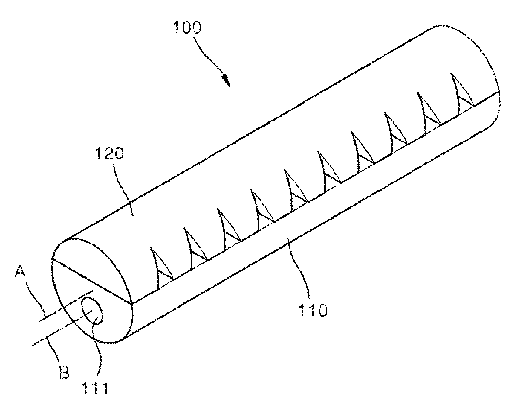
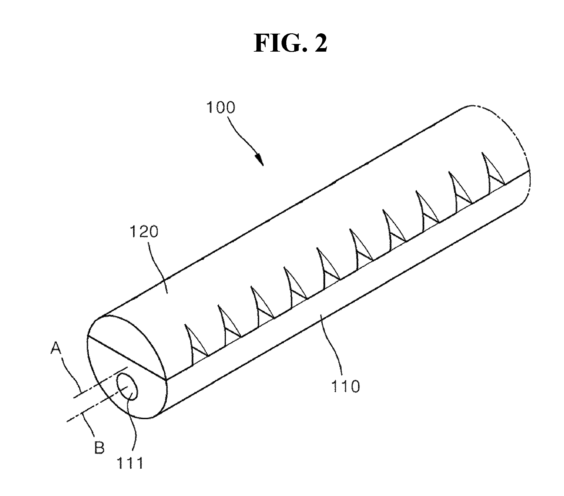
FIG. 2 is a perspective view which shows a front end of a direction-controllable drug injection catheter according to an embodiment of the present invention and shows that the front end has extended in a straight line;
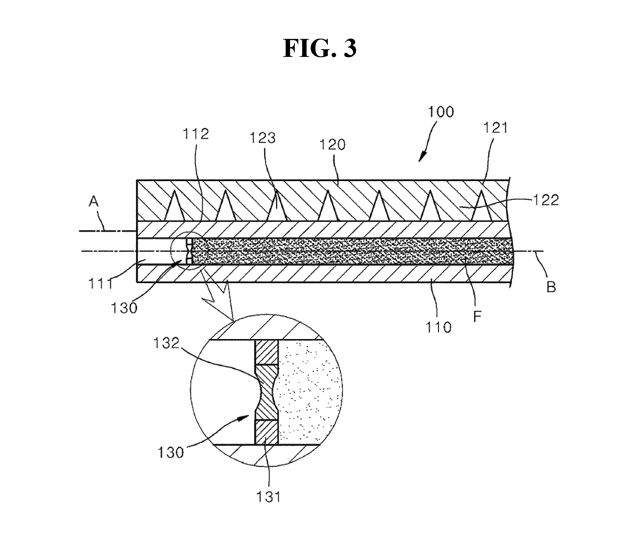
FIG. 3 is a longitudinal sectional view of the catheter shown in FIG. 2;
FIG. 4 is a longitudinal sectional view of the catheter shown in FIG. 2, which shows that the front end has been bent for direction control;
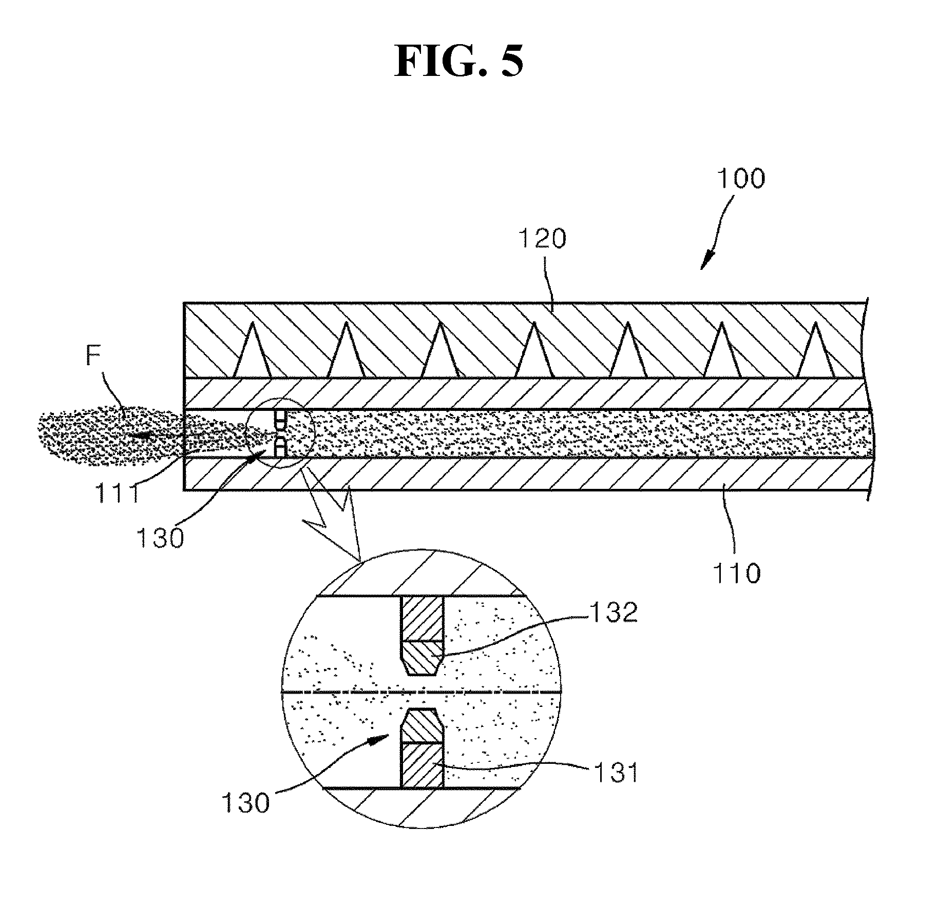
FIG. 5 is a longitudinal sectional view of the catheter shown in FIG. 2, which shows that drug is released;
FIGS. 6 and 7 are side views which show a front end of a direction-controllable drug injection catheter according to another embodiment of the present invention and show respectively a state where the front end has extended in a straight line and a state where the front end has been bent for direction control; and
FIGS. 8 and 9 show another embodiment of a channel opening and closing means shown in FIG. 3 and show respectively a closed state and an open state.
MODE FOR INVENTION
Hereafter, the configuration and operation of an embodiment of the present invention will be described in detail with reference to the drawings.
FIGS. 2 and 3 are a perspective view and a longitudinal sectional view of a front end of a direction-controllable drug injection catheter according to an embodiment of the present invention, which show that the front end has extended in a straight line. Referring to FIGS. 2 and 3, a catheter 100 according to the embodiment of the present invention has generally a circular cross section and extends along a central axis "A". The catheter 100 includes a drug injection part 110, a support 120, and a channel opening and closing means 130.
The drug injection part 110 extends along the central axis "A" and is made of a flexible material which is easily bent. A drug injection channel 111 through which a drug "F" passes is formed within the drug injection part 110. The drug injection channel 111 extends in parallel with the central axis "A" and is eccentrically located with respect to the central axis "A". That is, the central axis "A" of the catheter 100 and a central axis "B" of the drug injection channel 111 are parallel with each other and spaced apart from each other. The drug injection channel 111 is opened and closed by the channel opening and closing means 130. A flat bonding surface 112 to which the support 120 is bonded is formed on one side of the drug injection part 110.
The support 120 is bonded to the one side of the drug injection part 110 and extends along the central axis "A". The support 120 is an example of a steering structure which is rotationally asymmetric with respect to the central axis "A" disclosed in the patent claims. The steering structure is located only on one side of the drug injection channel and is changed according to the pressure change of the drug injection channel for steering. The support 120 is made of a flexible material in such a manner as to be bent together with the drug injection part 110. The support 120 is made of a material having a modulus of elasticity greater than that of the drug injection part 110 because the support 120 functions to structurally support the drug injection part 110. Preferably, the drug injection part 110 is made of rubber, and the support 120 is made of an elastic polymer material. On the opposite side to the drug injection channel 111 eccentrically located with respect to the central axis "A" of the catheter, the support 120 is bonded to the bonding surface 112 formed on the drug injection part 110. The support 120 includes a base part 121 and a plurality of bonding portions 122 protruding from the base part 121. The base part 121 is continuously formed along the longitudinal direction of the drug injection channel 111. The plurality of the bonding portions 122 protrude from the base part 121 and are arranged in a row along the longitudinal direction of the drug injection channel 111. The end of the bonding portion 122 is bonded to the bonding surface 112 formed on one side of the drug injection part 110. The bonding portion 122 becomes narrower toward the end thereof such that a gap is formed between two adjacent bonding portions 122. The two adjacent bonding portions 122 are connected to each other at the base part 121. A plurality of the gaps 123 are formed along the longitudinal direction of the drug injection channel 111. Due to the plurality of the gaps 123, the catheter 100 can be easily bent in a direction in which a distance between the ends of the two bonding portions 122 is reduced.
The channel opening and closing means 130 is installed in the drug injection part 110 and opens and closes the drug injection channel 111. The channel opening and closing means 130 includes a support wall 131 and a fracture portion 132. The support wall 131 is fixed on the wall of the drug injection channel 111. The fracture portion 132 is coupled to the central portion of the support wall 131. The fracture portion 132 is in the form of a film. When a pressure of the drug "F" becomes higher than a certain value in the drug injection channel 111, the fracture portion 132 is destroyed and opens the drug injection channel 111.
While the catheter 100 has been described above focusing on its configuration, the following description will focus on the operation of the catheter 100 in detail. Referring to FIG. 3, the drug "F" is filled in the drug injection channel 111. Without releasing the drug "F" filled in the drug injection channel 111 to the outside through the channel opening and closing means 130, the front end of the catheter 100 extends, as shown, in a straight line. In the state shown in FIG. 3, the catheter 100 is inserted. When the catheter 100 encounters a branch point while being inserted in the state of FIG. 3, the drug "F" in the drug injection channel 111 is inhaled in an opposite direction to the direction in which the catheter is inserted, so that a negative pressure is formed in the catheter 100. As a result, as shown in FIG. 4, the front end of the catheter 100 is bent and thus steering becomes possible. The direction of entry of the catheter 100 can be changed into a desired direction by rotating the catheter 100. Also, a degree to which the catheter 100 is bent (radius of curvature) can be controlled according to the magnitude of the negative pressure formed in the drug injection channel 111. By using the state shown in FIGS. 3 and 4, the front end of the catheter 100 is able to approach as close to a desired position as possible. Then, the pressure within the drug injection channel 111 is increased over a certain value by injecting the drug "F", and thus, the fracture portion 132 of the channel opening and closing means 130 is fractured. Accordingly, as shown in FIG. 5, the drug "F" is released to the outside.
FIG. 6 is a side view showing a direction-controllable drug injection catheter according to another embodiment of the present invention. Referring to FIG. 6, a catheter 200 includes the drug injection part 110, a support 220, and a channel opening and closing means (not shown). Since the drug injection part 110 and the channel opening and closing means (not shown) are the same as those described with reference to FIGS. 2 to 5, the detailed description thereof will be omitted.
The support 220 includes a base part 221 and a plurality of bonding portions 122 which protrude from the base part 221 and are spaced apart from each other by the gap 123. A plurality of incision portions 223 located corresponding to the gap 123 are formed in the base part 221. The incision portion 223 is formed on the outer surface of the support 120 at the opposite side to the drug injection part 110, so that the catheter can be, as shown in FIG. 7, more easily bent. When the catheter 200 extends, as shown in FIG. 6, in a straight line, incision surfaces of the incision portion 223 become in contact with each other. The structure of the bonding portion 122 and the gap 123 is the same as that described with reference to FIGS. 2 to 5. Therefore, the detailed description thereof will be omitted.
FIG. 8 shows another embodiment of the channel opening and closing means shown in FIG. 3. Referring to FIG. 8, the channel opening and closing means 230 includes a support wall 231 and an opening and closing member 235 coupled to the support wall 231. The support wall 231 is installed on the wall of the drug injection channel 111 formed in the drug injection part 110. A through-hole 232 through which the drug passes is formed in the central portion of the support wall 231. The opening and closing member 235 includes a cover 236, an extension rod 237, and an elastic support 238. The cover 236 has a plate shape and is located downstream with respect to the support wall 231. The cover 236 is larger than the through-hole 232 formed in the support wall 231, thereby opening and closing the through-hole 232. The extension rod 237 has an outer diameter less than that of the through-hole 232 and extends through the through-hole 232. The cover 236 is located on the downstream end of the extension rod 237. The elastic support 238 is located at the upstream of the extension rod 237. The support wall 231 is located between the cover 236 and the elastic support 238, and the elastic support 238 is integrally formed with the extension rod 237 on the opposite side to the cover 236. The elastic support 238 includes a plurality of support wings 239 which radially extend outwardly from the extension rod 237 and of which ends contact the support wall 231. Although not shown in detail, the drug is able to pass between the plurality of the support wings 239. The support wings 239 elastically support the extension rod 237 in a bent state where they are inclined toward the upstream the further it is radially and outwardly from the extension rod 237 and are more opened toward the end thereof contacting the support wall 231. Accordingly, the cover 236 receives a force toward the upstream, and thus, closes stably the through-hole 232. In this state, when a pressure by the drug in the drug injection channel 111 becomes higher than a certain value, the cover 236 is, as shown in FIG. 9, pushed downward, and thus, the through-hole 232 is opened, so that the drug is released as indicated by arrows.
While the present invention has been described by way of the embodiment thereof, the present invention is not limited to this. The embodiment can be modified or changed without departing from the spirit and scope of the present invention, and it can be understood by those skilled in the art that such modification and change belong to the present invention.
* * * * *
D00000
D00001
D00002
D00003
D00004
D00005
D00006
D00007
D00008
D00009
XML
uspto.report is an independent third-party trademark research tool that is not affiliated, endorsed, or sponsored by the United States Patent and Trademark Office (USPTO) or any other governmental organization. The information provided by uspto.report is based on publicly available data at the time of writing and is intended for informational purposes only.
While we strive to provide accurate and up-to-date information, we do not guarantee the accuracy, completeness, reliability, or suitability of the information displayed on this site. The use of this site is at your own risk. Any reliance you place on such information is therefore strictly at your own risk.
All official trademark data, including owner information, should be verified by visiting the official USPTO website at www.uspto.gov. This site is not intended to replace professional legal advice and should not be used as a substitute for consulting with a legal professional who is knowledgeable about trademark law.