Composite plug for arteriotomy closure and method of use
Hill , et al.
U.S. patent number 10,363,020 [Application Number 13/649,268] was granted by the patent office on 2019-07-30 for composite plug for arteriotomy closure and method of use. This patent grant is currently assigned to BOSTON SCIENTIFIC SCIMED INC.. The grantee listed for this patent is BOSTON SCIENTIFIC SCIMED, INC.. Invention is credited to James G. Hansen, Jason P. Hill, Susan M. Shoemaker.


| United States Patent | 10,363,020 |
| Hill , et al. | July 30, 2019 |
Composite plug for arteriotomy closure and method of use
Abstract
A method for the use of a composite plug for arteriotomy closure which includes an elongate core member and one or more layers disposed at least in part about the elongate core member. The composite plug may include an outer member at least partially surrounding the elongate core member. The method of use of the composite plug results in a progression of radial swelling along the longitudinal axis of the composite plug.
| Inventors: | Hill; Jason P. (Brooklyn Park, MN), Shoemaker; Susan M. (Elk River, MN), Hansen; James G. (Coon Rapids, MN) | ||||||||||
|---|---|---|---|---|---|---|---|---|---|---|---|
| Applicant: |
|
||||||||||
| Assignee: | BOSTON SCIENTIFIC SCIMED INC.
(Maple Grove, MN) |
||||||||||
| Family ID: | 42107480 | ||||||||||
| Appl. No.: | 13/649,268 | ||||||||||
| Filed: | October 11, 2012 |
Prior Publication Data
| Document Identifier | Publication Date | |
|---|---|---|
| US 20130035719 A1 | Feb 7, 2013 | |
Related U.S. Patent Documents
| Application Number | Filing Date | Patent Number | Issue Date | ||
|---|---|---|---|---|---|
| 12390289 | Feb 20, 2009 | 8292918 | |||
| Current U.S. Class: | 1/1 |
| Current CPC Class: | A61B 17/0057 (20130101); A61B 2017/00898 (20130101); A61B 2017/00526 (20130101); A61B 2017/00601 (20130101); A61B 2017/00004 (20130101) |
| Current International Class: | A61B 17/00 (20060101); A61B 17/03 (20060101) |
| Field of Search: | ;606/213 ;600/32 ;604/13,15,11 |
References Cited [Referenced By]
U.S. Patent Documents
| 3952377 | April 1976 | Morell |
| 5021059 | June 1991 | Kensey et al. |
| 5061274 | October 1991 | Kensey |
| 5084050 | January 1992 | Draenert |
| 5108421 | April 1992 | Fowler |
| 5129882 | July 1992 | Weldon et al. |
| 5192300 | March 1993 | Fowler |
| 5192302 | March 1993 | Kensey et al. |
| 5221259 | June 1993 | Weldon et al. |
| 5222974 | June 1993 | Kensey et al. |
| 5254105 | October 1993 | Haaga |
| 5275616 | January 1994 | Fowler |
| 5282827 | February 1994 | Kensey et al. |
| 5290310 | March 1994 | Makower et al. |
| 5292332 | March 1994 | Lee |
| 5310407 | May 1994 | Casale |
| 5312435 | May 1994 | Nash et al. |
| 5320639 | June 1994 | Rudnick |
| 5334216 | August 1994 | Vidal et al. |
| 5342393 | August 1994 | Stack |
| 5350399 | September 1994 | Erlebacher et al. |
| 5370660 | December 1994 | Weinstein et al. |
| 5383896 | January 1995 | Gershony et al. |
| 5383899 | January 1995 | Hammerslag |
| 5383905 | January 1995 | Golds et al. |
| 5391183 | February 1995 | Janzen et al. |
| 5411520 | May 1995 | Nash et al. |
| 5413571 | May 1995 | Katsaros et al. |
| 5415657 | May 1995 | Taymor-Luria |
| 5419765 | May 1995 | Weldon et al. |
| 5437631 | August 1995 | Janzen |
| 5441517 | August 1995 | Kensey et al. |
| 5443481 | August 1995 | Lee |
| 5447502 | August 1995 | Haaga |
| 5454833 | October 1995 | Boussignac et al. |
| 5478326 | December 1995 | Shiu |
| 5478352 | December 1995 | Fowler |
| 5486195 | January 1996 | Myers et al. |
| 5529577 | June 1996 | Hammerslag |
| 5531759 | July 1996 | Kensey et al. |
| 5540715 | July 1996 | Katsaros et al. |
| 5545178 | August 1996 | Kensey et al. |
| 5549633 | August 1996 | Evans et al. |
| 5571181 | November 1996 | Li |
| 5573518 | November 1996 | Haaga |
| 5591204 | January 1997 | Janzen et al. |
| 5593422 | January 1997 | Muijs Van de Moer et al. |
| 5601602 | February 1997 | Fowler |
| 5613974 | March 1997 | Andreas et al. |
| 5620461 | April 1997 | Muijs Van De Moer et al. |
| 5626601 | May 1997 | Gershony et al. |
| 5630833 | May 1997 | Katsaros et al. |
| 5649959 | July 1997 | Hannam et al. |
| 5653730 | August 1997 | Hammerslag |
| 5662681 | September 1997 | Nash et al. |
| 5676689 | October 1997 | Kensey et al. |
| 5700277 | December 1997 | Nash et al. |
| 5702421 | December 1997 | Schneidt |
| 5707393 | January 1998 | Kensey et al. |
| 5716375 | February 1998 | Fowler |
| 5725498 | March 1998 | Janzen et al. |
| 5725551 | March 1998 | Myers et al. |
| 5728114 | March 1998 | Evans et al. |
| 5728122 | March 1998 | Leschinsky et al. |
| 5728133 | March 1998 | Kontos |
| 5728134 | March 1998 | Barak |
| 5741223 | April 1998 | Janzen et al. |
| 5782860 | July 1998 | Epstein et al. |
| 5810884 | September 1998 | Kim |
| 5830130 | November 1998 | Janzen et al. |
| 5843124 | December 1998 | Hammerslag |
| 5853421 | December 1998 | Leschinsky et al. |
| 5861004 | January 1999 | Kensey et al. |
| 5871474 | February 1999 | Hermann et al. |
| 5871501 | February 1999 | Leschinsky et al. |
| 5906631 | May 1999 | Imran |
| 5916236 | June 1999 | Muijs Van de Moer et al. |
| 5922009 | July 1999 | Epstein et al. |
| 5935147 | August 1999 | Kensey et al. |
| 5935169 | August 1999 | Chan |
| 5947997 | September 1999 | Pavcnik et al. |
| 5948425 | September 1999 | Janzen et al. |
| 5951583 | September 1999 | Jensen et al. |
| 5957925 | September 1999 | Cook et al. |
| 6007561 | December 1999 | Bourque et al. |
| 6017359 | January 2000 | Gershony et al. |
| 6045569 | April 2000 | Kensey et al. |
| 6045570 | April 2000 | Epstein et al. |
| 6048357 | April 2000 | Kontos |
| 6048358 | April 2000 | Barak |
| 6054569 | April 2000 | Bennett et al. |
| 6056768 | May 2000 | Cates et al. |
| 6056769 | May 2000 | Epstein et al. |
| 6056770 | May 2000 | Epstein et al. |
| 6080183 | June 2000 | Tsugita et al. |
| 6083522 | July 2000 | Chu et al. |
| 6110184 | August 2000 | Weadock |
| 6120524 | September 2000 | Taheri |
| 6126675 | October 2000 | Shchervinsky et al. |
| 6162240 | December 2000 | Cates et al. |
| 6179863 | January 2001 | Kensey et al. |
| 6183496 | February 2001 | Urbanski |
| 6190400 | February 2001 | Van De Moer et al. |
| 6200329 | March 2001 | Fung et al. |
| 6251141 | June 2001 | Pierson, III et al. |
| 6261309 | July 2001 | Urbanski |
| 6296632 | October 2001 | Luscher et al. |
| 6296657 | October 2001 | Brucker |
| 6296658 | October 2001 | Gershony et al. |
| 6325789 | December 2001 | Janzen et al. |
| 6350274 | February 2002 | Li |
| 6368300 | April 2002 | Fallon et al. |
| 6368341 | April 2002 | Abrahamson |
| 6425911 | July 2002 | Akerfeldt et al. |
| 6461346 | October 2002 | Buelna |
| 6464712 | October 2002 | Epstein et al. |
| 6468293 | October 2002 | Bonutti et al. |
| 6475177 | November 2002 | Suzuki |
| 6475230 | November 2002 | Bonutti et al. |
| 6500152 | December 2002 | Illi |
| 6508828 | January 2003 | Akerfeldt et al. |
| 6524328 | February 2003 | Levinson |
| 6527734 | March 2003 | Cragg et al. |
| 6537299 | March 2003 | Hogendijk et al. |
| 6540735 | April 2003 | Ashby et al. |
| 6569187 | May 2003 | Bonutti et al. |
| 6572635 | June 2003 | Bonutti |
| 6592608 | July 2003 | Fisher et al. |
| 6596012 | July 2003 | Akerfeldt et al. |
| 6596014 | July 2003 | Levinson et al. |
| 6613070 | September 2003 | Redmond et al. |
| 6623509 | September 2003 | Ginn |
| 6632238 | October 2003 | Ginn et al. |
| 6645225 | November 2003 | Atkinson |
| 6656207 | December 2003 | Epstein et al. |
| 6663655 | December 2003 | Ginn et al. |
| 6682489 | January 2004 | Tenerz et al. |
| 6685727 | February 2004 | Fisher et al. |
| 6699261 | March 2004 | Cates et al. |
| 6712837 | March 2004 | .ANG.kerfeldt et al. |
| 6733515 | May 2004 | Edwards et al. |
| 6743195 | June 2004 | Zucker |
| 6749621 | June 2004 | Pantages et al. |
| 6764500 | July 2004 | Muijs Van De Moer et al. |
| 6780197 | August 2004 | Roe et al. |
| 6790220 | September 2004 | Morris et al. |
| 6818008 | November 2004 | Cates et al. |
| 6860895 | March 2005 | Akerfeldt et al. |
| 6863680 | March 2005 | Ashby |
| 6890342 | May 2005 | Zhu et al. |
| 6890343 | May 2005 | Ginn et al. |
| 6896692 | May 2005 | Ginn et al. |
| 6929655 | August 2005 | Egnelov et al. |
| 6939363 | September 2005 | .ANG.kerfeldt |
| 6942684 | September 2005 | Bonutti |
| 6955683 | October 2005 | Bonutti |
| 6964658 | November 2005 | Ashby et al. |
| 6969397 | November 2005 | Ginn |
| 7001398 | February 2006 | Carley et al. |
| 7008439 | March 2006 | Janzen et al. |
| 7008440 | March 2006 | Sing et al. |
| 7008441 | March 2006 | Zucker |
| 7008442 | March 2006 | Brightbill |
| 7025776 | April 2006 | Houser et al. |
| 7037323 | May 2006 | Sing et al. |
| 7044916 | May 2006 | Tenerz et al. |
| 7083635 | August 2006 | Ginn |
| 7192436 | March 2007 | Sing et al. |
| 7267679 | September 2007 | McGuckin, Jr. et al. |
| 7316704 | January 2008 | Bagaoisan et al. |
| 7322976 | January 2008 | Yassinzadeh |
| 7331979 | February 2008 | Khosravi et al. |
| 7331981 | February 2008 | Cates et al. |
| 7335220 | February 2008 | Khosravi et al. |
| 7488340 | February 2009 | Kauphusman et al. |
| 7491217 | February 2009 | Hendren et al. |
| 7695492 | April 2010 | Ashby et al. |
| 7749279 | July 2010 | Twomey et al. |
| 2002/0002889 | January 2002 | Ashby et al. |
| 2002/0016612 | February 2002 | Ashby et al. |
| 2002/0198562 | December 2002 | Akerfeldt et al. |
| 2003/0023267 | January 2003 | Ginn |
| 2003/0051735 | March 2003 | Pavcnik et al. |
| 2003/0088271 | May 2003 | Cragg et al. |
| 2004/0093025 | May 2004 | Egnelov |
| 2004/0098044 | May 2004 | Van de Moer et al. |
| 2004/0098046 | May 2004 | Tenerz et al. |
| 2004/0158287 | August 2004 | Cragg et al. |
| 2004/0172059 | September 2004 | Tenerz et al. |
| 2004/0204741 | October 2004 | Egnelov et al. |
| 2004/0215232 | October 2004 | Belhe et al. |
| 2004/0243007 | December 2004 | Tenerz et al. |
| 2005/0033360 | February 2005 | Sing et al. |
| 2005/0049637 | March 2005 | Morris et al. |
| 2005/0085852 | April 2005 | Ditter |
| 2005/0085855 | April 2005 | Forsberg |
| 2005/0096696 | May 2005 | Forsberg |
| 2005/0096697 | May 2005 | Forsberg et al. |
| 2005/0107827 | May 2005 | Paprocki |
| 2005/0125031 | June 2005 | Pipenhagen et al. |
| 2005/0137624 | June 2005 | Fallman |
| 2005/0169974 | August 2005 | Tenerz et al. |
| 2005/0177189 | August 2005 | Ginn et al. |
| 2005/0267521 | December 2005 | Forsberg |
| 2005/0267528 | December 2005 | Ginn et al. |
| 2006/0004408 | January 2006 | Morris et al. |
| 2006/0030886 | February 2006 | Clark |
| 2006/0034930 | February 2006 | Khosravi et al. |
| 2006/0047313 | March 2006 | Khanna et al. |
| 2006/0058844 | March 2006 | White et al. |
| 2006/0100664 | May 2006 | Pai et al. |
| 2006/0135996 | June 2006 | Schwartz et al. |
| 2006/0142797 | June 2006 | Egnelov |
| 2006/0173492 | August 2006 | Akerfeldt et al. |
| 2006/0178682 | August 2006 | Boehlke |
| 2006/0206146 | September 2006 | Tenerz |
| 2006/0229669 | October 2006 | Mirizzi et al. |
| 2006/0229672 | October 2006 | Forsberg |
| 2006/0229673 | October 2006 | Forsberg |
| 2006/0229674 | October 2006 | Forsberg |
| 2006/0265006 | November 2006 | White et al. |
| 2006/0265007 | November 2006 | White et al. |
| 2006/0265008 | November 2006 | Maruyama et al. |
| 2006/0276871 | December 2006 | Lamson et al. |
| 2007/0032823 | February 2007 | Tegg |
| 2007/0032824 | February 2007 | Terwey |
| 2007/0038244 | February 2007 | Morris et al. |
| 2007/0038245 | February 2007 | Morris et al. |
| 2007/0073337 | March 2007 | Abbott et al. |
| 2007/0073345 | March 2007 | Pipenhagen et al. |
| 2007/0083231 | April 2007 | Lee |
| 2007/0083232 | April 2007 | Lee |
| 2007/0129757 | June 2007 | Armstrong |
| 2007/0135842 | June 2007 | Van de Moer et al. |
| 2007/0276433 | November 2007 | Huss |
| 2008/0004657 | January 2008 | Obermiller et al. |
| 2008/0065121 | March 2008 | Kawaura et al. |
| 2008/0071311 | March 2008 | White et al. |
| 2008/0097521 | April 2008 | Khosravi et al. |
| 2008/0109030 | May 2008 | Houser et al. |
| 2008/0114394 | May 2008 | Houser et al. |
| 2009/0024106 | January 2009 | Morris |
| 2009/0069843 | March 2009 | Agnew |
| 2009/0118757 | May 2009 | Burnett et al. |
| 2009/0171388 | July 2009 | Dave et al. |
| 1568326 | Aug 2005 | EP | |||
| 1671591 | Jun 2006 | EP | |||
| 06339483 | Dec 1994 | JP | |||
| 2000258673 | Sep 2000 | JP | |||
| 2002515797 | May 2002 | JP | |||
| 2006508712 | Mar 2006 | JP | |||
| 2007501100 | Jan 2007 | JP | |||
| 2008518742 | Jun 2008 | JP | |||
| 2008526448 | Jul 2008 | JP | |||
| 8911301 | Nov 1989 | WO | |||
| 2006078578 | Jul 2006 | WO | |||
| 2006124238 | Nov 2006 | WO | |||
Attorney, Agent or Firm: Seager, Tufte & Wickhem LLP
Parent Case Text
CROSS-REFERENCE TO RELATED APPLICATIONS
This application is a divisional application of U.S. application Ser. No. 12/390,289 filed Oct. 19, 2010, now U.S. Pat. No. 8,292,918.
Claims
What is claimed is:
1. A method of use of a composite arteriotomy plug comprising: positioning a composite arteriotomy plug having an elongate core member, a distal end, and a proximal end within a tissue tract adjacent to a vessel puncture, wherein the composite arteriotomy plug varies along an axial extent of the composite arteriotomy with regard to at least one of composition, placement, and thickness of one or more layers disposed about the elongate core member of the composite arteriotomy plug as a function of longitudinal distance from the distal end of the composite arteriotomy plug; controlling longitudinal exposure of the composite arteriotomy plug to body fluids within the tissue tract by altering at least one of the composition, placement, and thickness of the one or more layers disposed about the elongate core member of the composite arteriotomy plug as a function of longitudinal distance from the distal end of the composite arteriotomy plug; and allowing the composite arteriotomy plug to expand radially upon contact with bodily fluids with a swelling profile in which swelling is generally initiated at or near the distal end of the composite arteriotomy plug and continues at more proximal locations as a function of time.
2. The method of claim 1, wherein the elongate core member comprises a gelatin foam and the one or more layers disposed about the elongate core member comprise a material selected from a hydrogel, a hemostatic material, and combinations thereof.
3. The method of claim 1, wherein one layer disposed about the elongate core member of the composite arteriotomy plug comprises an outer member at least partially surrounding the elongate core member, said outer member having a distal end and a proximal end.
4. The method of claim 3, wherein a portion of the elongate core member extends distally with respect to the outer member.
5. The method of claim 4, wherein distal of the outer member, a lateral cross-section of the composite arteriotomy plug includes only the elongate core member.
6. The method of claim 3, wherein proximal of the elongate core member, a lateral cross-section of the composite arteriotomy plug includes only the outer member.
7. The method of claim 3, wherein the elongate core member of the composite arteriotomy plug is compressed prior to applying the outer member at least partially surrounding the elongate core member.
8. The method of claim 3, wherein at least some of the one or more layers of the composite arteriotomy plug are positioned between the elongate core member and the outer member.
9. The method of claim 8, wherein at least some of the one or more layers of the composite arteriotomy plug are not covered by the outer member.
10. The method of claim 1, wherein one or more regions of the composite arteriotomy plug has been removed.
11. The method of claim 10, wherein removing one or more regions of the composite arteriotomy plug provides improved fluid access to an interior of the composite arteriotomy plug.
12. The method of claim 11, wherein improved fluid access to the interior of the composite arteriotomy plug alters a local rate of radial expansion of the composite arteriotomy plug.
13. The method of claim 10, wherein removing one or more regions of the composite arteriotomy plug creates one or more of notches, grooves and helical grooves.
14. The method of claim 1, wherein the one or more layers are continuous.
15. The method of claim 1, wherein the one or more layers are discontinuous.
16. The method of claim 1, wherein the composite arteriotomy plug further comprises an axial lumen adapted to receive a suture.
17. The method of claim 16, wherein a suture is received within the axial lumen of the composite arteriotomy plug.
18. The method of claim 16, wherein the suture is attached to an anchor adjacent to a vessel puncture.
Description
BACKGROUND OF THE INVENTION
A large number of diagnostic and interventional procedures involve the percutaneous introduction of instrumentation into a vein or artery. For example, coronary angioplasty, angiography, atherectomy, stenting of arteries, and many other procedures often involve accessing the vasculature through a catheter placed in the femoral artery or other blood vessel. Once the procedure is completed and the catheter or other instrumentation is removed, bleeding from the punctured artery must be controlled.
Traditionally, external pressure is applied to the skin entry site to stem bleeding from a puncture wound in a blood vessel. Pressure is continued until hemostasis has occurred at the puncture site. In some instances, pressure must be applied for up to an hour or more during which time the patient is uncomfortably immobilized. Further, external pressure to close the vascular puncture site works best when the vessel is close to the skin surface but may be unsuitable for patients with substantial amounts of subcutaneous adipose tissue since the skin surface may be a considerable distance from the vascular puncture site.
There are several approaches to close the vascular puncture site including the use of anchor and plug systems as well as suture systems. Internal suturing of the blood vessel puncture requires a specially designed suturing device. These suturing devices involve a significant number of steps to perform suturing and require substantial expertise. Additionally, when releasing hemostasis material at the puncture site and withdrawing other devices out of the tissue tract, the currently employed approaches to sealing the puncture may only partially occlude the tract thereby allowing blood to seep out of the puncture.
SUMMARY
The disclosure pertains to a composite plug for arteriotomy closure comprising an elongate core member having a distal end, a proximal end, and a lumen connecting the distal end and the proximal end, said lumen sized to receive a suture, and one or more layers disposed at least in part about the plug, wherein the core member comprises a gelatin foam and the one or more layers which may include a hydrogel and/or a hemostatic material, further wherein the plug has been partially compacted in a radial dimension.
In another aspect, the disclosure pertains to a method of manufacturing a composite plug for arteriotomy closure comprising the steps of providing a gelatin foam blank larger than a desired core member; removing excess gelatin foam from the gelatin foam blank larger than a desired core member to form a core member having a distal end and a proximal end; providing a lumen sized to receive a suture, said lumen connecting the distal end and the proximal end of core member; providing at least one layer disposed about the plug, which said layer may include a hydrogel and/or a hemostatic material; providing a suture within the lumen which extends distally and proximately from the core member; and partially compacting the plug in a radial dimension.
In yet another aspect, the disclosure pertains to a method of deploying a composite plug for arteriotomy closure comprising the steps of providing a composite plug comprising an elongate core member having a distal end, a proximal end, and a lumen connecting the distal end and the proximal end, said lumen sized to receive a suture and one or more layers disposed at least in part about the plug, wherein the core member comprises a gelatin foam and one or more layers comprising a material which may include a hydrogel and/or a hemostatic material, further wherein the plug includes a suture extending through the lumen; radially compacting the plug; inserting the compacted plug into a temporary containment sheath; providing an anchoring site adjacent to a vessel; attaching the suture to the anchoring site; inserting the temporary containment sheath at least partially into a tract adjacent to the vessel; ejecting the composite plug from the temporary containment sheath; and positioning the composite plug adjacent to the vessel and within the tract.
It is within the scope of the disclosure to include within the arteriotomy closure plug an outer member which at least partially surrounds the core member as well as additional layers which may include a hydrogel and/or a hemostatic material applied to the outer member.
BRIEF DESCRIPTION OF DRAWINGS
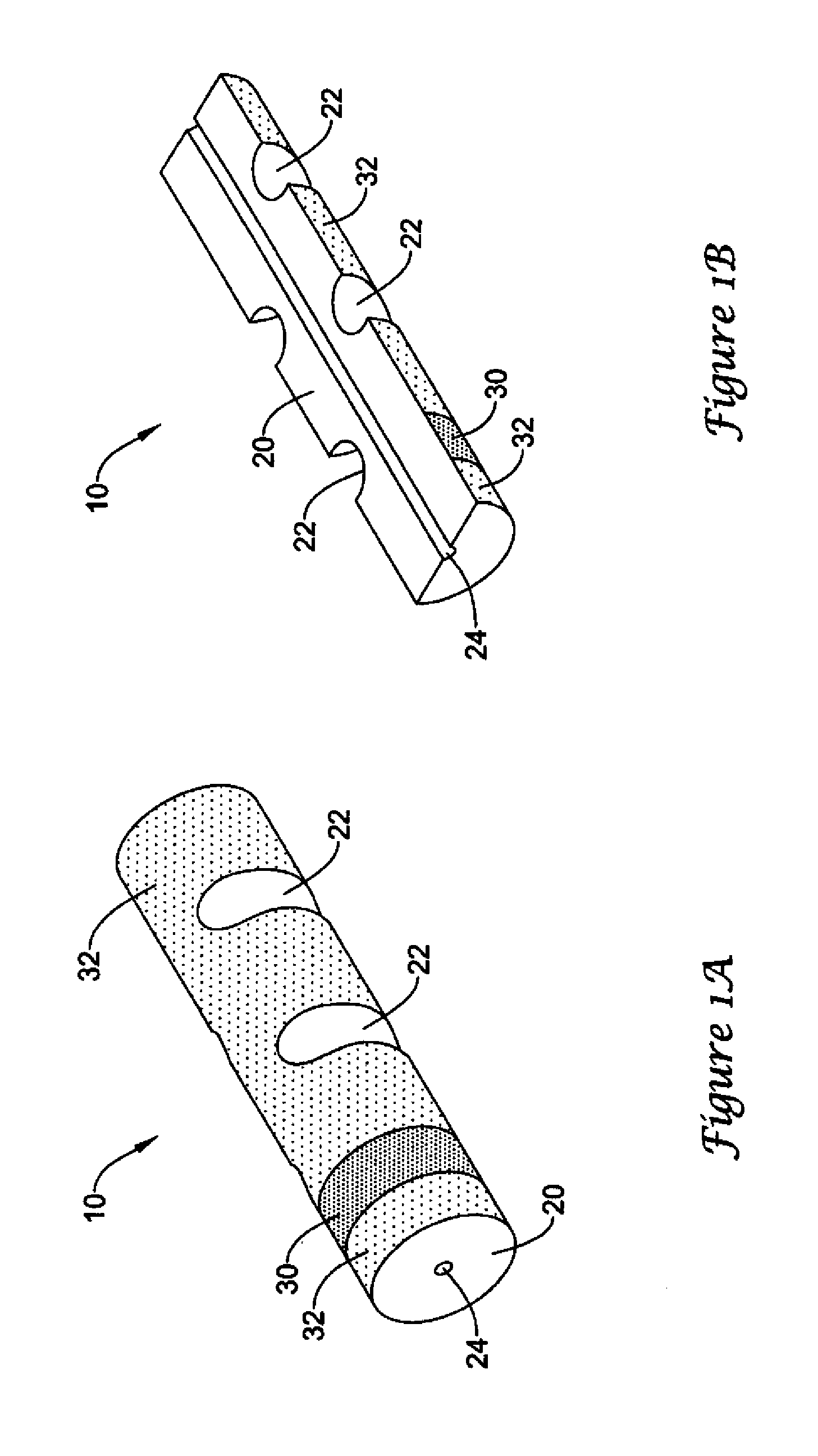
FIG. 1A is a perspective view of a composite arteriotomy closure plug of the invention.
FIG. 1B is a perspective view of a longitudinally sectioned composite arteriotomy closure plug of FIG. 1A.
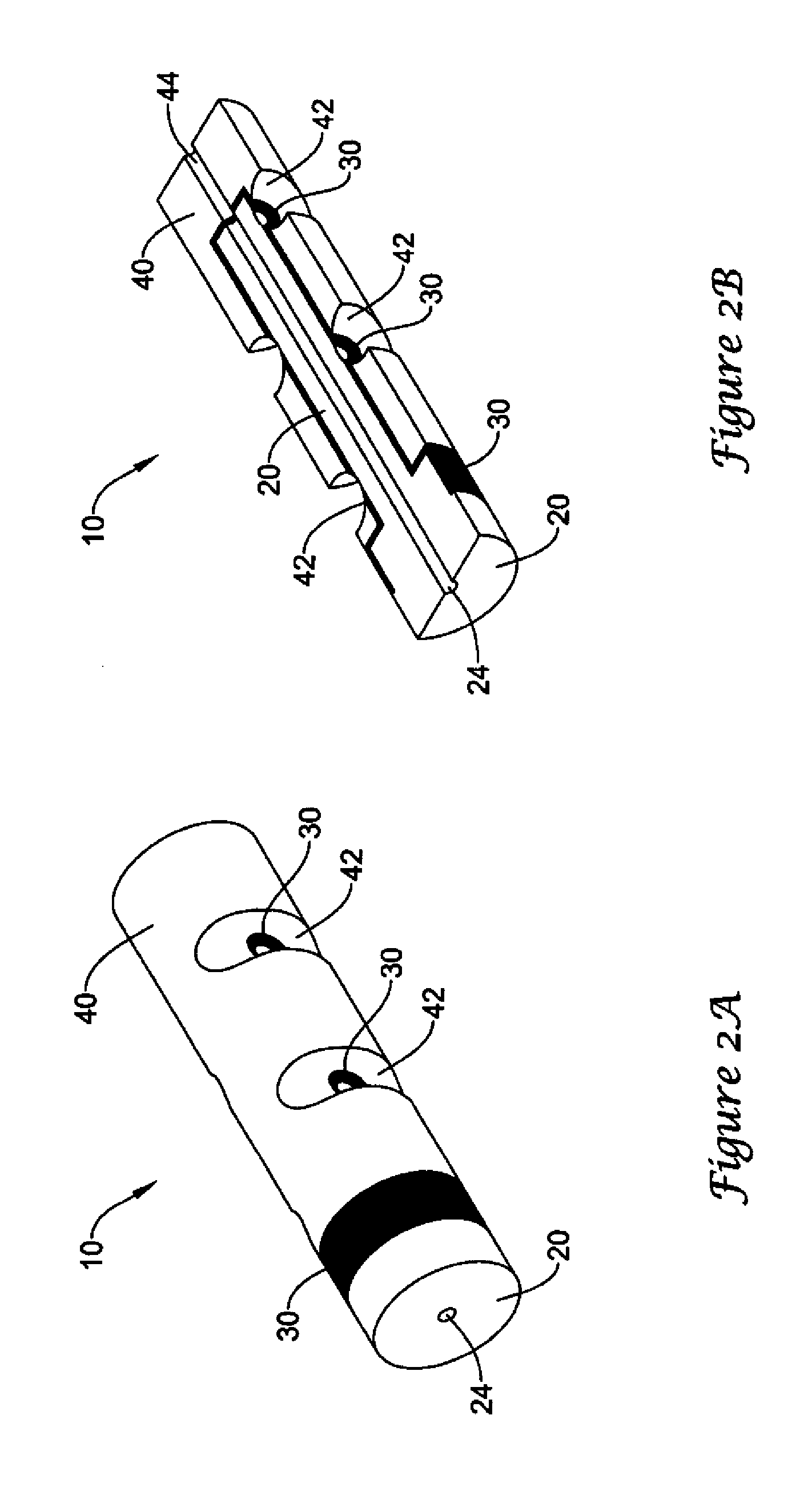
FIG. 2A is a perspective view of a composite arteriotomy closure plug of the invention.
FIG. 2B is a perspective view of a longitudinally sectioned composite arteriotomy closure plug of FIG. 2A.
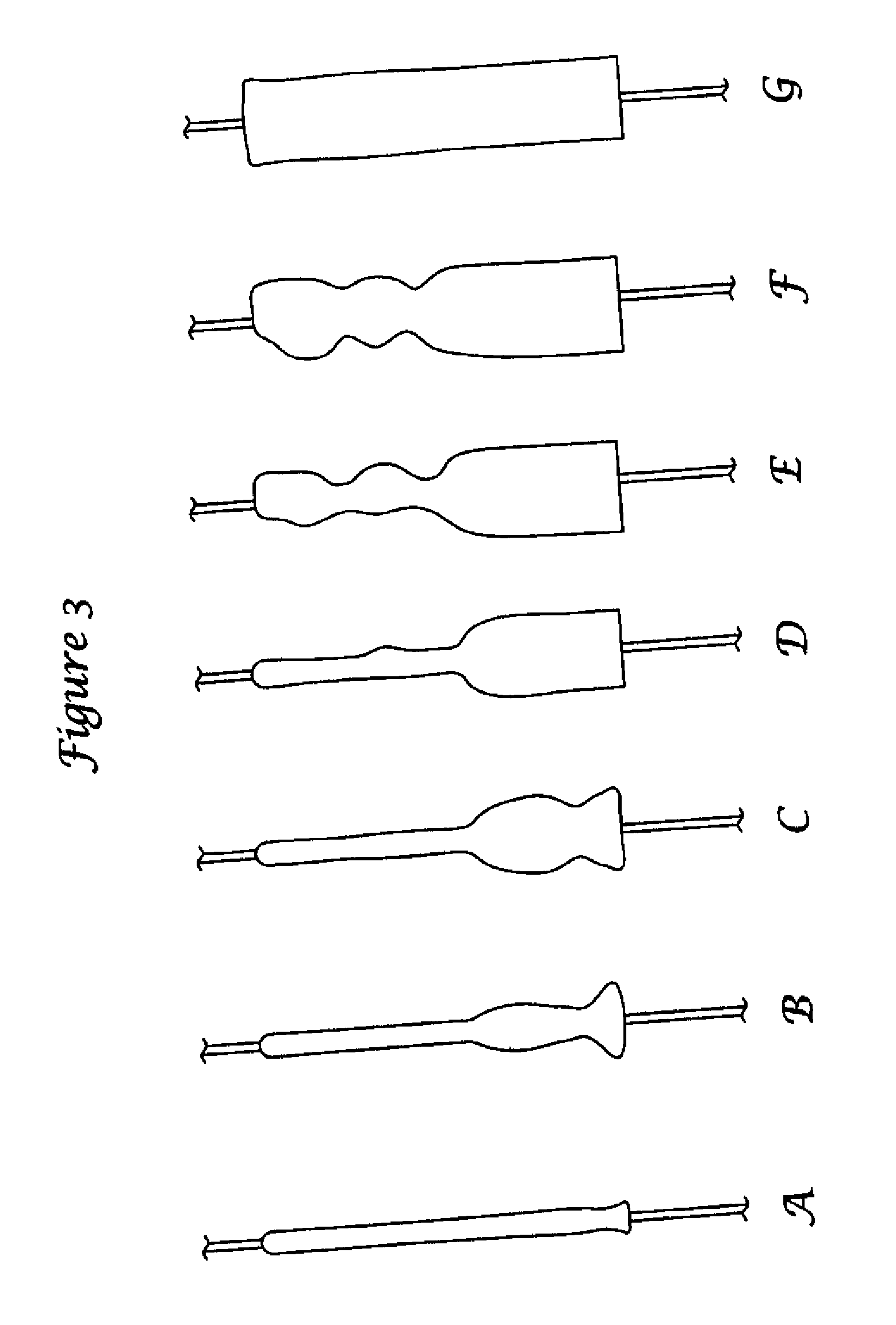
FIGS. 3A-G are schematic representations of stages in the expansion of a composite arteriotomy closure plug of the invention.
FIG. 4 is a schematic cross-section of a composite arteriotomy closure plug of the invention during delivery.
DETAILED DESCRIPTION
The following description should be read with reference to the drawings wherein like reference numerals indicate like elements throughout the several views. The drawings, which are not necessarily to scale, are not intended to limit the scope of the claimed invention. The detailed description and drawings illustrate example embodiments of the claimed invention.
All numbers are herein assumed to be modified by the term "about." The recitation of numerical ranges by endpoints includes all numbers subsumed within that range (e.g., 1 to 5 includes 1, 1.5, 2, 2.75, 3, 3.80, 4, and 5).
As used in this specification and the appended claims, the singular forms "a", "an", and "the" include the plural referents unless the content clearly dictates otherwise. As used in this specification and the appended claims, the term "or" is generally employed in its sense including "and/or" unless the content clearly dictates otherwise.
Embodiments are described herein in the context of a hemostatic pressure plug. Those of ordinary skill in the art will appreciate that the following detailed description is illustrative only and is not intended to be in any way limiting. In the interest of clarity, not all of the routine features of the implementations described herein are shown and described.
Providing hemostasis at a blood vessel puncture site is important for procedures such as percutaneous access to prevent bleeding and hematoma. Thus, a solution to facilitate hemostasis at a puncture site may be achieved by deploying a flexible hemostatic plug within the puncture tract.
Referring now to FIGS. 1A-B, which together illustrate a composite arteriotomy closure plug (10) having an elongate core member (20) provided with a lumen (24) extending axially from a distal end to a proximal end and sized to accept a suture (not shown), it will be seen that the core member has been provided with a first layer (30) and second layers (32). The core member may be formed from absorbable gelatin foam such as GELFOAM.RTM. (Pharmacia & Upjohn, Inc., Bridgewater, N.J.), Surgifoam.TM. (Johnson & Johnson, New Brunswick, N.J.), CURASPON.RTM. (CuraMedical BV, Assendelft, Netherlands), GELITASPON.RTM. (Gelita Medical BV, Amsterdam, Netherlands), GELASPON.RTM. (Juvalis--Bernburg, Germany), or similar materials which may become available.
Layers (30) and (32), which may be continuous or discontinuous and which may optionally overlap, may be formulated from materials including a hydrogel, a hemostatic material, an antimicrobial, a growth promoter, thrombus enhancing agents, and the like. It will also be appreciated that the layers may be discrete layers applied to the plug by, for example, extrusion or coating or may be present as generally surface regions of the plug which contain elevated amounts of the layer material. These regions of enriched material may be introduced by allowing the layer components to migrate into the plug material. The hydrogel component, if present, may include any of the commonly employed biocompatible hydrogels, such as polyethylene glycols (PEG) on the molecular weight range of about 600 to 6,000, including PEG 900, PEG 3350, and PEG 6000 (Sigma-Aldrich, St. Louis, Mo.). Of the hemostatic materials commonly available, starch such as BleedArrest.TM. Clotting Powder (Hemostasis, LLC, St. Paul, Minn.), PerClot.TM. (Starch Medical, San Jose, Calif.), SuperClot.TM. (Starch Medical, San Jose, Calif.) or Arista.TM. AH (Medafor, Minneapolis, Minn.) may be employed alone or in combination with polyethylene glycol as a binder. The hemostatic material may be mixed with the binder or may be adhered to the plug component(s) by contacting the plug component with the hemostatic material under conditions in which one or both have moistened surfaces. For example, a hydrogel material may be applied from solution by one of the common techniques such spraying and when the carrier has partially evaporated to a tacky state, the hemostatic material may be applied by impingement or by tumbling. In some embodiments, the hemostatic material may be applied directly to the plug where it may be mechanically retained within the pores of the foam. In addition to serving as a binder for a hemostatic material, the hydrogel component may also be used to modulate the rate of swelling of the gelatin foam and, in some embodiments, may serve as a lubricant during the deployment of the composite plug. The composite arteriotomy closure plug (10) of FIGS. 1A-B may optionally include horizontal or vertical slits, notches, grooves, helical grooves, and the like which are believed to facilitate axial compression of the plug and to provide controlled buckling and folding of the plug. Notches (22) are illustrated.
FIGS. 2A-B, which together illustrate a composite arteriotomy closure plug (10) having an elongate core member (20) provided with a lumen (24), additionally include an outer member (40) having the general shape of a cylindrical cap which mates with a core member (20) having a T-shaped axial cross-section resulting in a core member which resembles a cylindrical distal segment joined to a reduced diameter cylindrical proximal segment. The outer member (40) has at least a first lumen which may receive at least a portion of the core member and typically has a second lumen (44) sized and aligned with the lumen (24) of the core member to receive the suture (not shown) extending through the core member to provide a continuous path therefor. The exterior surfaces of the core member distal segment and the outer member proximal end may have substantially the same cross-section to provide a smooth join. As in the monolithic plug of FIGS. 1A-B, the plug of FIGS. 2A-B may optionally include horizontal or vertical slits, notches, grooves, helical grooves, and the like which are believed to facilitate axial compression of the plug and to provide controlled buckling and folding of the plug. Notches (42) are illustrated. Suitable modifications to control buckling of the composite plugs of this disclosure may be found, for example in co-pending application Serial No. and Ser. No. 12/389,847, filed Feb. 20, 2009, incorporated herein by reference in their entirety.
It will be appreciated that any given embodiment may have more than one core member and/or more than one outer member if desired. Such multi-component plugs may be useful in those configurations which would be difficult to fabricate from only one or two members. For example, distal and proximal outer members in the form of caps may be applied to a completely contained core member.
The layers associated with the closure plug of FIGS. 2A-B may have compositions similar to those discussed above. The layers may be positioned about the core member, between the core member and the outer member, and/or about the outer member. Although generally circumferential layers have bee depicted in FIGS. 1A through 2B, it will be appreciated that the layers may be applied as longitudinal stripes, as spirals, as patterned regions, and the like to achieve a swelling profile.
FIGS. 3 A-G are illustrative of the progression in swelling which may occur when a composite arteriotomy closure plug is exposed to an appropriate fluid, in this case by full submersion in water. The radial expansion profile along the plug, as a function of time, may be altered by controlling the composition, placement, and thickness of layers applied to the plug and by the positioning of horizontal or vertical slits, notches, grooves, and the like. In addition, the profile may be controlled by mechanically altering the local porosity of the gelatin foam components. In some embodiments, it may be desirable to alter the expansion profile to favor early expansion near the distal end of the composite plug which is believed to stabilize the plug within the tract and to minimize proximal movement within the tract under the influence of any arterial blood pressure which may leak from the vessel. Additionally, it is believed that a swelling profile in which swelling is generally initiated at or near the distal end of the composite plug and continues at progressively more proximal locations may tend to press the composite plug distally into the tract to an extent which may resist ejection of the plug without undesirable intrusion into the vessel.
FIG. 4 illustrates schematically the deployment of a composite plug (10) for arteriotomy closure within a wound tract adjacent to an arterial puncture. The arterial wall (100) has been punctured proximate the anchoring site (70). In this illustrative example, an anchoring site for the suture (50) has been provided as a loop attached to a toggle or patch disposed within the lumen (110) of the artery although other anchoring site mechanisms are known and may be used with the composite arteriotomy closure plug. The composite plug (10) has been radially compressed within temporary sheath (60) and advanced through the tract to a position adjacent to the arterial puncture. As illustrated, the composite plug comprises a core member (20) and an outer member (40) which has been advanced along suture (50) to the deployment position. The composite plug (10) may then be ejected from the temporary sheath (60) by conventional means, which have been omitted for clarity, and the temporary sheath may be withdrawn, typically through a cannula within the wound tract. Following or concurrent with ejection, the composite plug may be axially compressed within the wound tract. A variety of techniques may be used alone or in combination. For example, the axial suture (50) may be placed in tension against a suture anchor site (70) while a slip knot is advanced distally along the suture. Compression may be augmented by the use of a pushrod. It is believed that the presence of horizontal or vertical slits, notches, grooves, helical grooves, and the like facilitate axial compression and folding in a controlled manner while minimizing forces which might tend to result in undesirable intrusion of the plug into the vessel. In other embodiments, the anchoring site may not need to provide a separate anchoring structure, but may simply provide sufficient fluid to create initial distal swelling of the composite plug which will serve to anchor the plug within the tract.
As noted above, in some embodiments one or more regions of the composite plug may be modified by horizontal or vertical slits or material may be removed to provide notches, grooves, helical grooves, and the like which may lower axial compression forces on the composite plug during deployment within a wound tract. Smooth compression is desirable to control buckling and folding of the composite plug while avoiding excessive internal stresses which may tend to allow the suture to tear the composite plug. In addition to facilitating compression, the removed regions may provide improved fluid access to the interior of the composite plug including, but not limited to, access to any interior layers which may be present therein.
In some embodiments, the layer or layers applied to components of the composite plug may provide a continuous layer which covers all or part of the surface of the plug. In other embodiments, the layers may be discontinuous as in longitudinal or circumferential stripes. When more than one layer is present on a surface, the layers may be spaced-apart, may abut, or may overlap. In addition to stripes or bands, the layers may be applied in a pattern-wise manner. One or more layers may be present between components of the composite plug. The layers associated with a composite plug may all have a similar composition or the composition may vary from layer to layer. In some embodiments, the composition of a single layer may vary along the length of the composite plug. In yet other embodiments a layer may comprise a region of higher concentration of layer material within a core member or outer member.
The components and placement of layers may be selected to enhance or to impede the uptake of fluid by the composite plug and so may be used to control the intermediate shapes which the composite plug adopts as it swells locally in response to fluid contact. For example, partially filling the surface structure of the gelatin foam with hydrogel, particularly a higher molecular weight hydrogel, will often impede uptake of fluid and so will delay the swelling of the composite plug locally. Conversely, lower molecular weight hydrogels may serve as wetting agents or surfactants and may enhance the uptake of fluids thereby accelerating swelling.
Although it is within the scope of the disclosure to apply the layers by any method known in the art, dip coating and spray coating have been found to be appropriate and convenient. The hydrogel has been applied from solutions in water, isopropanol, and ethanol. Alcoholic solutions of polyethylene glycol have been found to have little effect on the gelatin foam structure, while aqueous solutions, especially when used for dip coating, may partially collapse the foam structure near the surface. Polyethylene glycol applied to the gelatin foam prior to radial compression has been found to increase the volumetric expansion upon hydration. In some embodiments, it may be desirable to distribute polyethylene glycol, or other hydrogel material, throughout the gelatin foam by applying the hydrogel from an alcoholic solution by dip coating. The distribution of PEG within the foam may be controlled by varying the temperature and dip time. The resulting distribution may be essentially uniform or may gradually increase in concentration from the center toward the surface. Addition of suitable surfactants may increase the rate of penetration of PEG solutions through the gelatin foam. Drying of the plug following dip coating may be accomplished with or without the application of vacuum. The drying process may influence shrinkage and hydration volume expansion capacity without significantly affecting leak performance.
In addition to providing a layer comprising a material such as a hydrogel and/or hemostatic material on a portion of the surface of a core member and/or outer member, the surfaces of the composite plug may be further modified by local mechanical compression or elongation, partially collapsing the gelatin foam using heat, exposure of the surface to water followed by drying, or the like.
In some embodiments, in addition to a core member and layers thereon, the composite plug may include an outer member at least partially surrounding the core member. The outer member may be fabricated form the same gelatin foam as the core member, a gelatin foam having a different density, or a different material such as collagen. The outer member may have one or more lumens therethrough. One such lumen may be sized to receive a suture and generally aligned with the lumen of the core member when the core member and the outer member are assembled. An outer member lumen may be sized and positioned to accept at least a portion of the core member therein either before or after partial radial compression of that portion of the core member to be contained within the outer member.
In some embodiments, the core member will have a generally T-shaped axial cross-section and generally circular transverse cross-sections. An outer member for a core member having a generally T-shaped axial cross-section may have a mating generally U-shaped axial cross-section. In such embodiments, the cross-section of the enlarged distal end of the core member may be similar to the cross-section of the distal end of the outer member to provide a smooth transition between the two components. In other embodiments, the composite plug may comprise multiple core members and/or multiple outer members to facilitate fabrication of more complex composite plugs. It will be appreciated that transverse cross-sections of the core member(s) and the outer member(s) are not necessarily circular and that the overall shape of the composite plug is not necessarily cylindrical although those shapes may be somewhat easier to fabricate and have been selected for the nonlimiting illustrative examples. In some embodiments, the outer member may extend a short distance proximal of the proximal end of the core member. In these and other embodiments, the distal end of the core element may extend a short distance distal of the distal end of the outer element. Although the dimensions of the composite plug may be varied depending on anticipated usage sites, the length of the composite plug will often be greater than the average diameter of the plug and advantageously may be selected to be about four to five times the average diameter prior to radial compression although greater or lesser ratios may be employed.
In those embodiments which include at least one core member and at least one outer member, one or more layers including one or more of a hydrogel and a hemostatic material may be disposed between the at least one core member and at least one outer member. Although the layer or layers disposed between a core member and an outer layer usefully may tend to adhere the two components together, that is not a necessary function of the layer or layers. In those embodiments in which at least one layer is disposed between a core member and an outer member, any slits, notches, grooves, or the like which may be present may optionally expose or improve fluid access to a portion of the at least one layer. Optionally, the slits, notches, or grooves may penetrate the at least one layer.
The composite plug of the disclosure may be formed, for example, by removing excess gelatin foam from a blank larger than the desired core member and/or outer element. These components may then be provided with a lumen connecting the distal and proximal ends of the components, said lumen sized to receive a suture therethrough. If an outer member is to be used, the lumen thereof may be enlarged to accommodate at least a portion of the core member in a partially compressed or uncompressed state. At least one layer may be disposed about the components of the plug, said layer including at least one of a hydrogel and a hemostatic material. In some embodiments, the at least one layer may be applied to a core member. In other embodiments, the at least one layer may be applied to an outer member. In yet other embodiments, the at least one layer may be applied to both core members and outer members. The core member(s) and outer member(s) may be assembled by positioning at least a portion of the core member(s) within a lumen of a corresponding outer member or members with or without an interposed layer comprising a material including at least one of a hydrogel and a hemostatic material. A suture may be provided within the lumen of the core member(s) and may extend through lumens of any outer members which may be present thereby extending at least from the distal end of the composite plug to the proximal end of the composite plug. The assembled composite plug may then be provided with one or more horizontal or vertical slits, notches, grooves, helical grooves, or the like and at least partially compacted in a radial dimension. In some embodiments, a portion of the composite arteriotomy closure plug may be mechanically modified to alter the permeability of the plug to fluids. The mechanical modification may, for example, take the form of flexing the plug to partially break portions of the foam structure or of selectively piercing the plug to provide fluid access channels. Such modification may occur before or after application of one or more layers and before or after radial compression. Additional mechanical modification may occur after the formation of notches or grooves. The composite plug may be subjected to a drying or desiccating step to remove excess moisture prior to storage or use.
It is believed that the ability of the composite arteriotomy closure plug to seal a wound tract has at least two major contributors. The first is an enhanced ability to clot blood which may be attributed to contributions from both the gelatin foam and the hemostatic material. In addition to the clotting function, the gelatin foam, hemostatic material, and the hydrogel are each capable of swelling upon hydration to expand within the wound tract thereby closing any potential leak paths. Appropriately chosen hemostatic and hydrogel materials may also increase the viscosity of fluids within the tract further enhancing the sealing action. Although the relative amounts of the various components employed in a composite arteriotomy plug of the disclosure may vary with the particular materials selected, hydrogel loadings of 0 to about 3:1 and hemostatic material loadings of about 0.25:1 to about 3:1 by weight on the weight of the foam will often be appropriate.
As shown in FIGS. 3A-G, the localization of hydrogel and hemostatic material in layers, as well as mechanical modification of plug porosity, may be used to control the progression of swelling along the length of the disclosed composite closure plug to a degree not possible with a conventional arteriotomy closure plug which tends to swell uniformly upon exposure to bodily fluids. By initiating swelling near the distal end and delaying swelling near the proximal end, the plug may be provided with early stability within the wound tract, attributable to the soft wide base, while maintaining firmness for deliverability near the proximal end. As discussed above, progressive swelling from the distal end toward the proximal end of the plug is believed to resist expulsion of the plug under the influence of arterial blood pressure.
Testing of a variety of composite plugs of the disclosure versus unmodified gelatin foam plugs, as well as commercially available plugs, has shown a reduction in peak by-pass water flow rates within a simulated tract of the order of 3.5:1 to 28:1 in the initial minute of exposure. Further, unmodified gelatin foam plugs allowed sustained leakage during the second through the tenth minute of exposure which ranged between 10 and 16 ml/min compared to essentially zero leakage for composite plugs under the same test conditions. A commercially available collagen arteriotomy closure plug allowed sustained leakage of 3 to 4 ml/min under the same conditions.
Once fabricated and compressed, the composite arteriotomy closure plug may be inserted into a temporary containment sheath for delivery to the vicinity of the vessel puncture. Apparatus suitable for delivering the composite arteriotomy closure plug is disclosed in co-pending application Ser. No. 12/390,241, filed Feb. 20, 2009 incorporated herein by reference in its entirety. In some embodiments, the radial compression which accompanies insertion into a temporary containment sheath may be of the order of 3:1, 8:1, or even 10:1. A degree of elastic rebound may be expected. In some embodiments, the suture may be attached to an anchor adjacent to a vessel puncture. The anchor site may be any of the anchor sites known in the art. For example, it may take the form of a loop attached to a toggle or patch located within the punctured vessel. Other forms of anchor site are also contemplated. For example, the anchor site may be formed by the distal lip of a catheter, cannula, or the temporary sheath within which the composite plug is contained if the lip serves to position the suture extending from the distal end of the composite plug adjacent to the vessel puncture during the deployment of the composite plug. Following insertion of the temporary containment sheath within the wound tract and tensioning of the distal suture to ensure that the composite plug is properly positioned within the tract, the composite plug may be ejected from the temporary containment sheath and, if necessary, further oriented within the tract by manipulation of the proximal end of the plug as it begins to expand. In addition, the composite plug may be axially compressed with attendant buckling and or folding within the wound tract. In other embodiments, a suture may not be required for proper deployment of the composite plug and swelling of the distal end upon exposure to fluids may suffice to anchor the plug within the tract. The containment sheath, as well as any other apparatus remaining within the wound tract, may then be removed to allow the composite plug to expand and seal the tract.
Various modifications and alterations of this invention will become apparent to those skilled in the art without departing from the scope and principles of this invention, and it should be understood that this invention is not to be unduly limited to the illustrative embodiments set forth hereinabove. All publications and patents are herein incorporated by reference to the same extent as if each individual publication or patent was specifically and individually indicated to be incorporated by reference.
* * * * *
D00000
D00001
D00002
D00003
D00004
XML
uspto.report is an independent third-party trademark research tool that is not affiliated, endorsed, or sponsored by the United States Patent and Trademark Office (USPTO) or any other governmental organization. The information provided by uspto.report is based on publicly available data at the time of writing and is intended for informational purposes only.
While we strive to provide accurate and up-to-date information, we do not guarantee the accuracy, completeness, reliability, or suitability of the information displayed on this site. The use of this site is at your own risk. Any reliance you place on such information is therefore strictly at your own risk.
All official trademark data, including owner information, should be verified by visiting the official USPTO website at www.uspto.gov. This site is not intended to replace professional legal advice and should not be used as a substitute for consulting with a legal professional who is knowledgeable about trademark law.