IV access device having an angled paddle grip
Sonderegger , et al. July 23, 2
U.S. patent number 10,357,636 [Application Number 15/286,198] was granted by the patent office on 2019-07-23 for iv access device having an angled paddle grip. This patent grant is currently assigned to Becton, Dickinson and Company. The grantee listed for this patent is Becton, Dickinson and Company. Invention is credited to Jonathan Karl Burkholz, Bart D. Peterson, Ralph L. Sonderegger.


| United States Patent | 10,357,636 |
| Sonderegger , et al. | July 23, 2019 |
IV access device having an angled paddle grip
Abstract
An IV access device can include a needle hub having an angled paddle grip to facilitate insertion of the catheter at a low angle. The angled paddle grip can also minimize any interference that an extension tube or stabilization platform may cause during insertion. By employing an angled paddle grip, the catheter can be inserted while maintaining the stabilization platform in an orientation that is substantially parallel to the patient's skin. Also, in cases where the extension tube may run parallel with the stabilization platform, the angled paddle grip can prevent the extension tube from extending into the patient's skin during insertion. This will prevent the stabilization platform and/or the extension tube from catching on the patient's skin or otherwise inhibiting a smooth insertion of the catheter.
| Inventors: | Sonderegger; Ralph L. (Farmington, UT), Peterson; Bart D. (Farmington, UT), Burkholz; Jonathan Karl (Salt Lake City, UT) | ||||||||||
|---|---|---|---|---|---|---|---|---|---|---|---|
| Applicant: |
|
||||||||||
| Assignee: | Becton, Dickinson and Company
(Franklin Lakes, NJ) |
||||||||||
| Family ID: | 57223758 | ||||||||||
| Appl. No.: | 15/286,198 | ||||||||||
| Filed: | October 5, 2016 |
Prior Publication Data
| Document Identifier | Publication Date | |
|---|---|---|
| US 20170120012 A1 | May 4, 2017 | |
Related U.S. Patent Documents
| Application Number | Filing Date | Patent Number | Issue Date | ||
|---|---|---|---|---|---|
| 62247621 | Oct 28, 2015 | ||||
| 62247596 | Oct 28, 2015 | ||||
| 62296383 | Feb 17, 2016 | ||||
| 62247599 | Oct 28, 2015 | ||||
| 62247617 | Oct 28, 2015 | ||||
| 62247607 | Oct 28, 2015 | ||||
| 62247624 | Oct 28, 2015 | ||||
| 62247626 | Oct 28, 2015 | ||||
| 62296385 | Feb 17, 2016 | ||||
| Current U.S. Class: | 1/1 |
| Current CPC Class: | A61M 25/0606 (20130101); A61M 25/0637 (20130101); A61M 25/0693 (20130101); A61M 25/0097 (20130101) |
| Current International Class: | A61M 25/00 (20060101); A61M 25/06 (20060101) |
| Field of Search: | ;604/164 |
References Cited [Referenced By]
U.S. Patent Documents
| 3046984 | July 1962 | Eby |
| 3547119 | December 1970 | Hall et al. |
| 3589361 | June 1971 | Loper et al. |
| 3827434 | August 1974 | Thompson et al. |
| 3853127 | December 1974 | Spademan |
| 3859998 | January 1975 | Thomas et al. |
| 4003403 | January 1977 | Nehring |
| 4043346 | August 1977 | Mobley et al. |
| 4099528 | July 1978 | Sorenson et al. |
| 4149539 | April 1979 | Cianci |
| 4172448 | October 1979 | Brush |
| 4177809 | December 1979 | Moorehead |
| 4193399 | March 1980 | Robinson |
| 4200096 | April 1980 | Charvin |
| 4269186 | May 1981 | Loveless et al. |
| 4311137 | January 1982 | Gerard |
| 4317445 | March 1982 | Robinson |
| 4326519 | April 1982 | D'Alo et al. |
| 4353369 | October 1982 | Muetterties et al. |
| 4362156 | December 1982 | Feller, Jr. et al. |
| 4365630 | December 1982 | McFarlane |
| 4387879 | June 1983 | Tauschinski |
| 4419094 | December 1983 | Patel |
| 4449693 | May 1984 | Gereg |
| 4496348 | January 1985 | Genese et al. |
| 4525157 | June 1985 | Vaillancourt |
| 4531935 | July 1985 | Berryessa |
| 4682980 | July 1987 | Suzuki |
| 4701162 | October 1987 | Rosenberg |
| 4703761 | November 1987 | Rathbone et al. |
| 4758225 | July 1988 | Cox et al. |
| 4765588 | August 1988 | Atkinson |
| 4772264 | September 1988 | Cragg |
| 4813939 | March 1989 | Marcus |
| 4834708 | May 1989 | Pillari |
| 4842591 | June 1989 | Luther |
| 4874377 | October 1989 | Newgard et al. |
| 4894052 | January 1990 | Crawford |
| 4917668 | April 1990 | Haindl |
| 4917671 | April 1990 | Chang |
| 4925444 | May 1990 | Orkin et al. |
| 4935010 | June 1990 | Cox et al. |
| 4950257 | August 1990 | Hibbs et al. |
| 4966586 | October 1990 | Vaillancourt |
| D315822 | March 1991 | Ryan |
| 5032116 | July 1991 | Peterson et al. |
| 5041097 | August 1991 | Johnson |
| 5053014 | October 1991 | Van Heugten |
| 5057087 | October 1991 | Harmon |
| 5059186 | October 1991 | Yamamoto et al. |
| 5062836 | November 1991 | Wendell |
| 5064416 | November 1991 | Newgard et al. |
| 5084023 | January 1992 | Lemieux |
| 5085645 | February 1992 | Purdy et al. |
| 5108374 | April 1992 | Lemieux |
| 5127905 | July 1992 | Lemieux |
| 5135504 | August 1992 | McLees |
| 5154703 | October 1992 | Bonaldo |
| 5156596 | October 1992 | Balbierz et al. |
| 5176653 | January 1993 | Metais |
| 5176662 | January 1993 | Bartholomew et al. |
| 5201717 | April 1993 | Wyatt et al. |
| 5211634 | May 1993 | Vaillancourt |
| 5215525 | June 1993 | Sturman |
| 5215528 | June 1993 | Purdy et al. |
| 5215529 | June 1993 | Fields et al. |
| 5226883 | July 1993 | Katsaros et al. |
| 5234410 | August 1993 | Graham et al. |
| 5242411 | September 1993 | Yamamoto et al. |
| 5254097 | October 1993 | Schock et al. |
| 5267971 | December 1993 | Brimhall |
| 5269764 | December 1993 | Vetter et al. |
| 5273546 | December 1993 | McLaughlin et al. |
| 5290222 | March 1994 | Feng et al. |
| 5290246 | March 1994 | Yamamoto et al. |
| 5295969 | March 1994 | Fischell et al. |
| 5306243 | April 1994 | Bonaldo |
| 5312359 | May 1994 | Wallace |
| 5328482 | July 1994 | Sircom et al. |
| 5330435 | July 1994 | Vaillancourt |
| 5342315 | August 1994 | Rowe et al. |
| 5350363 | September 1994 | Goode et al. |
| 5352205 | October 1994 | Dales et al. |
| 5356381 | October 1994 | Ensminger et al. |
| 5368029 | November 1994 | Holcombe et al. |
| 5405323 | April 1995 | Rogers et al. |
| 5447501 | September 1995 | Karlsson et al. |
| 5456675 | October 1995 | Wolbring et al. |
| 5458658 | October 1995 | Sircom |
| 5487728 | January 1996 | Vaillancourt |
| 5509912 | April 1996 | Vaillancourt et al. |
| 5520666 | May 1996 | Choudhury et al. |
| 5542932 | August 1996 | Daugherty |
| 5549566 | August 1996 | Elias et al. |
| 5549576 | August 1996 | Patterson et al. |
| 5549577 | August 1996 | Siegel et al. |
| 5562631 | October 1996 | Bogert |
| 5562633 | October 1996 | Wozencroft |
| 5573510 | November 1996 | Isaacson |
| 5575769 | November 1996 | Vaillancourt |
| 5575777 | November 1996 | Cover et al. |
| 5584809 | December 1996 | Gaba |
| 5599310 | February 1997 | Bogert |
| 5601536 | February 1997 | Crawford et al. |
| 5613663 | March 1997 | Schmidt et al. |
| 5651772 | July 1997 | Arnett |
| 5657963 | August 1997 | Hinchliffe et al. |
| 5676656 | October 1997 | Brimhall |
| 5690612 | November 1997 | Lopez et al. |
| 5690619 | November 1997 | Erskine |
| 5697907 | December 1997 | Gaba |
| 5697914 | December 1997 | Brimhall |
| 5697915 | December 1997 | Lynn |
| 5699821 | December 1997 | Paradis |
| 5700244 | December 1997 | Kriesel |
| 5700250 | December 1997 | Erskine |
| 5704919 | January 1998 | Kraus et al. |
| 5718688 | February 1998 | Wozencroft |
| 5730123 | March 1998 | Lorenzen et al. |
| 5738144 | April 1998 | Rogers |
| 5749856 | May 1998 | Zadini et al. |
| 5749861 | May 1998 | Guala et al. |
| 5772636 | June 1998 | Brimhall et al. |
| 5800399 | September 1998 | Bogert et al. |
| 5806831 | September 1998 | Paradis |
| 5810780 | September 1998 | Brimhall et al. |
| 5817069 | October 1998 | Arnett |
| 5843046 | December 1998 | Motisi et al. |
| 5853393 | December 1998 | Bogert |
| 5882345 | March 1999 | Yoon |
| 5911710 | June 1999 | Barry et al. |
| 5935109 | August 1999 | Donnan |
| 5935110 | August 1999 | Brimhall |
| 5947932 | September 1999 | Desecki et al. |
| 5954698 | September 1999 | Pike |
| 5961497 | October 1999 | Larkin |
| 5967490 | October 1999 | Pike |
| 6039302 | March 2000 | Cote, Sr. et al. |
| 6056726 | May 2000 | Isaacson |
| 6077244 | June 2000 | Botich et al. |
| 6117108 | September 2000 | Woehr et al. |
| 6142981 | November 2000 | Heck et al. |
| 6171287 | January 2001 | Lynn et al. |
| 6206851 | March 2001 | Prosl |
| 6221047 | April 2001 | Greene et al. |
| 6224569 | May 2001 | Brimhall |
| 6273869 | August 2001 | Vaillancourt |
| 6287278 | September 2001 | Woehr et al. |
| D451600 | December 2001 | Crawford et al. |
| 6379332 | April 2002 | Van Landuyt |
| D458678 | June 2002 | Cindrich |
| D458994 | June 2002 | Cindrich |
| 6461362 | October 2002 | Halseth et al. |
| 6485473 | November 2002 | Lynn |
| 6497994 | December 2002 | Kafrawy |
| 6506181 | January 2003 | Meng et al. |
| D469870 | February 2003 | Niermann et al. |
| 6565542 | May 2003 | Kumar et al. |
| 6575960 | June 2003 | Becker et al. |
| 6595954 | July 2003 | Luther et al. |
| 6595981 | July 2003 | Huet |
| 6616630 | September 2003 | Woehr et al. |
| 6652486 | November 2003 | Bialecki et al. |
| 6663592 | December 2003 | Rhad et al. |
| 6689102 | February 2004 | Greene |
| 6695814 | February 2004 | Greene et al. |
| 6699221 | March 2004 | Vaillancourt |
| 6709419 | March 2004 | Woehr |
| 6719726 | April 2004 | Meng et al. |
| 6740063 | May 2004 | Lynn |
| D491266 | June 2004 | Cindrich et al. |
| D492031 | June 2004 | Cindrich et al. |
| 6749588 | June 2004 | Howell et al. |
| D492774 | July 2004 | Cindrich et al. |
| 6837884 | January 2005 | Woloszko |
| 6883778 | April 2005 | Newton et al. |
| 7008404 | March 2006 | Nakajima |
| 7347839 | March 2008 | Hiejima |
| 7396346 | July 2008 | Nakajima |
| 7470254 | December 2008 | Basta et al. |
| D592302 | May 2009 | Stokes et al. |
| 7670317 | March 2010 | Cindrich et al. |
| 7694403 | April 2010 | Moulton |
| 7736339 | June 2010 | Woehr et al. |
| 7905856 | March 2011 | McGuckin, Jr. et al. |
| 7914494 | March 2011 | Hiejima |
| 8066670 | November 2011 | Cluff et al. |
| 8066675 | November 2011 | Cindrich et al. |
| 8070725 | December 2011 | Christensen |
| 8357119 | January 2013 | Stout et al. |
| 8361020 | January 2013 | Stout et al. |
| 8388583 | March 2013 | Stout et al. |
| 8574203 | November 2013 | Stout et al. |
| 8597252 | December 2013 | Burkholz et al. |
| 8641675 | February 2014 | Stout et al. |
| 8679063 | March 2014 | Stout et al. |
| D713522 | September 2014 | Woehr et al. |
| 2001/0053895 | December 2001 | Vaillancourt |
| 2002/0072712 | June 2002 | Nool et al. |
| 2002/0082546 | June 2002 | Crank et al. |
| 2002/0177814 | November 2002 | Meng et al. |
| 2003/0083620 | May 2003 | Luther et al. |
| 2004/0078003 | April 2004 | Smith et al. |
| 2004/0092889 | May 2004 | Ferguson et al. |
| 2004/0102735 | May 2004 | Moulton et al. |
| 2004/0181192 | September 2004 | Cuppy |
| 2004/0193112 | September 2004 | Glazier et al. |
| 2004/0204681 | October 2004 | Thoresen et al. |
| 2004/0225260 | November 2004 | Villa et al. |
| 2004/0243060 | December 2004 | Rossi et al. |
| 2004/0243061 | December 2004 | McGurk |
| 2005/0273019 | December 2005 | Conway et al. |
| 2005/0277879 | December 2005 | Daga |
| 2006/0163515 | July 2006 | Ruschke |
| 2007/0043334 | February 2007 | Guala |
| 2007/0083157 | April 2007 | Belley et al. |
| 2007/0083162 | April 2007 | O'Reagan et al. |
| 2007/0093778 | April 2007 | Cindrich et al. |
| 2007/0191777 | August 2007 | King |
| 2007/0225648 | September 2007 | Winsor et al. |
| 2007/0233007 | October 2007 | Adams |
| 2008/0039796 | February 2008 | Nakajima |
| 2008/0108944 | May 2008 | Woehr et al. |
| 2008/0132832 | June 2008 | McKinnon et al. |
| 2008/0255473 | October 2008 | Dalebout et al. |
| 2008/0287906 | November 2008 | Burkholz et al. |
| 2009/0054845 | February 2009 | Puhasmagi et al. |
| 2009/0099431 | April 2009 | Dalebout et al. |
| 2009/0287189 | November 2009 | Suwito |
| 2010/0204648 | August 2010 | Stout et al. |
| 2010/0204675 | August 2010 | Woehr et al. |
| 2010/0222746 | September 2010 | Burkholz |
| 2010/0280455 | November 2010 | Ogawa et al. |
| 2011/0046570 | February 2011 | Stout et al. |
| 2011/0054403 | March 2011 | Tanabe et al. |
| 2011/0130728 | June 2011 | McKinnon |
| 2012/0016265 | January 2012 | Peterson et al. |
| 2012/0016307 | January 2012 | Burkholz et al. |
| 2012/0053523 | March 2012 | Harding |
| 2013/0090608 | April 2013 | Stout et al. |
| 2013/0218082 | August 2013 | Hyer et al. |
| 2013/0237925 | September 2013 | Trainer et al. |
| 2014/0046258 | February 2014 | Stout et al. |
| 2014/0107584 | April 2014 | Rosenberg et al. |
| 2014/0364809 | December 2014 | Isaacson et al. |
| 2015/0224296 | August 2015 | Winsor |
| 2017/0120008 | May 2017 | Burkholz et al. |
| 2017/0120014 | May 2017 | Harding et al. |
| 2017/0216535 | August 2017 | Mao |
| 2 133 053 | Mar 1995 | CA | |||
| 101879341 | Nov 2010 | CN | |||
| 102440822 | May 2012 | CN | |||
| 102716541 | Oct 2012 | CN | |||
| 203852671 | Oct 2014 | CN | |||
| 20 2009 009 602 | Dec 2009 | DE | |||
| 0 268 480 | May 1988 | EP | |||
| 0 732 120 | Sep 1996 | EP | |||
| 0 812 601 | Dec 1997 | EP | |||
| 0 993 839 | Apr 2000 | EP | |||
| 1 306 097 | May 2003 | EP | |||
| 1 679 043 | Jul 2006 | EP | |||
| 1 884 257 | Feb 2008 | EP | |||
| 1 944 049 | Jul 2008 | EP | |||
| 2022421 | Feb 2009 | EP | |||
| 2 044 970 | Apr 2009 | EP | |||
| 2 327 434 | Jun 2011 | EP | |||
| 2508466 | Jun 2014 | GB | |||
| 2011045544 | Mar 2011 | JP | |||
| 2014108112 | Jun 2014 | JP | |||
| 88/07388 | Oct 1988 | WO | |||
| 97/45151 | Dec 1997 | WO | |||
| 98/42393 | Oct 1998 | WO | |||
| 99/34849 | Jul 1999 | WO | |||
| 01/12254 | Feb 2001 | WO | |||
| 02/096495 | Dec 2002 | WO | |||
| 2004/032995 | Apr 2004 | WO | |||
| 2004/082727 | Sep 2004 | WO | |||
| 2004/087247 | Oct 2004 | WO | |||
| 2004/098685 | Nov 2004 | WO | |||
| 2006/037638 | Apr 2006 | WO | |||
| 2008/022258 | Feb 2008 | WO | |||
| 2008/045761 | Apr 2008 | WO | |||
| 2008/052790 | May 2008 | WO | |||
| 2008/058132 | May 2008 | WO | |||
| 2008/058133 | May 2008 | WO | |||
| 2009/114833 | Sep 2009 | WO | |||
| 2010/093791 | Aug 2010 | WO | |||
| 2010/111283 | Sep 2010 | WO | |||
| 2010/111285 | Sep 2010 | WO | |||
| 2011/055287 | May 2011 | WO | |||
| 2011/109542 | Sep 2011 | WO | |||
| 2016/007442 | Jan 2016 | WO | |||
| 2017/062579 | Apr 2017 | WO | |||
Other References
|
Silva, Elson, Email Regarding "Respecting Hydrology Science and IP Rights--US Pat. Application 20110130728," pp. 1-6 (Jun. 2, 2011). cited by applicant. |
Primary Examiner: Gray; Phillip A
Attorney, Agent or Firm: Kirton & McConkie Metcalf; Lloyd Stinger; Kevin
Parent Case Text
RELATED APPLICATIONS
This application claims the benefit of U.S. Provisional Patent Application Ser. No. 62/247,621, which was filed Oct. 28, 2015, U.S. Provisional Patent Application No. 62/247,596, which was filed on Oct. 28, 2015, U.S. Provisional Patent Application No. 62/296,383, which was filed on Feb. 17, 2016, U.S. Provisional Patent Application No. 62/247,599, which was filed Oct. 28, 2015, U.S. Provisional Patent Application No. 62/247,617, which was filed on Oct. 28, 2015, U.S. Provisional Patent Application Ser. No. 62/247,607, which was filed Oct. 28, 2015, U.S. Provisional Patent Application Ser. No. 62/247,624, which was filed Oct. 28, 2015, U.S. Provisional Application No. 62/247,626, which was filed on Oct. 28, 2015, and U.S. Provisional Application No. 62/296,385, which was filed on Feb. 17, 2016, each of which is incorporated herein by reference in their entirety.
Claims
The invention claimed is:
1. An IV access device comprising: a catheter adapter from which a catheter extends distally, the catheter adapter including a wing; and a needle hub from which a needle extends distally, the needle hub being configured to be coupled to the catheter adapter such that the needle extends through the catheter; wherein the needle hub further includes a paddle grip oriented at an angle and configured to lift the wing to a corresponding angle.
2. The IV access device of claim 1, wherein the wing is formed of a flexible material that allows the wing to pivot from a flat orientation into an angled orientation when the paddle grip is adjacent the wing.
3. The IV access device of claim 1, wherein the wing is coupled to the catheter adapter via a hinged connection, the hinged connection allowing the wing to pivot from a flat orientation to an angled orientation when the paddle grip is adjacent the wing.
4. The IV access device of claim 1, wherein, when the needle hub is not coupled to the catheter adapter, the wing is positioned in a flat orientation.
5. The IV access device of claim 1, wherein the wing is a first wing, the catheter adapter further comprising a second wing that is positioned opposite the first wing.
6. The IV access device of claim 5, wherein the paddle grip is a first paddle grip, the needle hub further comprising a second paddle grip that is positioned opposite the first paddle grip.
7. The IV access device of claim 6, wherein the second paddle grip is oriented at an angle.
8. The IV access device of claim 6, further comprising: an extension tube coupled to the catheter adapter.
9. The IV access device of claim 8, wherein the extension tube is coupled to the second wing.
10. The IV access device of claim 1, wherein the paddle grip is a first paddle grip, the needle hub further comprising a second paddle grip that is positioned opposite the first paddle grip.
11. The IV access device of claim 1 wherein the needle hub further comprises a flash chamber at a proximal end of the needle hub, a proximal end of the needle being in fluid communication with the flash chamber.
12. The IV access device of claim 1, wherein the paddle grip is oriented at an angle that causes the wing to be substantially parallel with the paddle grip when the paddle grip is adjacent the wing.
13. The IV access device of claim 1, wherein the wing is a first wing and the catheter adapter comprises a second wing opposite the first wing, the second wing being positioned in a flat orientation when the paddle grip positions the first wing in an angled orientation.
14. The IV access device of claim 1, wherein the wing extends outwardly beyond the paddle grip.
15. The IV access device of claim 1, wherein the paddle grip extends outwardly beyond the wing.
16. An IV access device comprising: a catheter adapter from which a catheter extends distally, the catheter adapter including a wing; and a needle hub from which a needle extends distally, the needle hub being configured to be coupled to the catheter adapter such that the needle extends through the catheter; wherein the needle hub further includes a paddle grip that is configured to be positioned adjacent the wing when the needle hub is coupled to the catheter adapter, wherein, when the paddle grip is forced into contact with the wing, the paddle grip causes the wing to be elevated into an angled orientation.
17. The IV access device of claim 16, wherein the paddle grip is forced into contact with the wing when the paddle grip and wing are squeezed between a thumb and finger of a clinician during insertion of the catheter.
18. The IV access device of claim 16, wherein the wing is a first wing, the catheter adapter comprising a second wing positioned opposite the first wing, the second wing incorporating an extension tube.
19. An IV access device comprising: a catheter adapter from which a catheter extends distally, the catheter adapter including a first wing that extends from a first side of the catheter adapter and a second wing that extends from a second side of the catheter adapter opposite the first side; an extension tube that couples to the catheter adapter on the second side; and a needle hub from which a needle extends distally, the needle hub being configured to be coupled to the catheter adapter such that the needle extends through the catheter, the needle hub including a paddle grip that is configured to be positioned adjacent the first wing when the needle hub is coupled to the catheter adapter, wherein the paddle grip oriented at an angle and configured to lift the first wing to a corresponding angle.
20. The IV access device of claim 19, wherein the first and second wing are configured to extend outwardly within a common plan, the paddle grip causing the first wing to be positioned at an angle with respect to the common plane.
Description
BACKGROUND
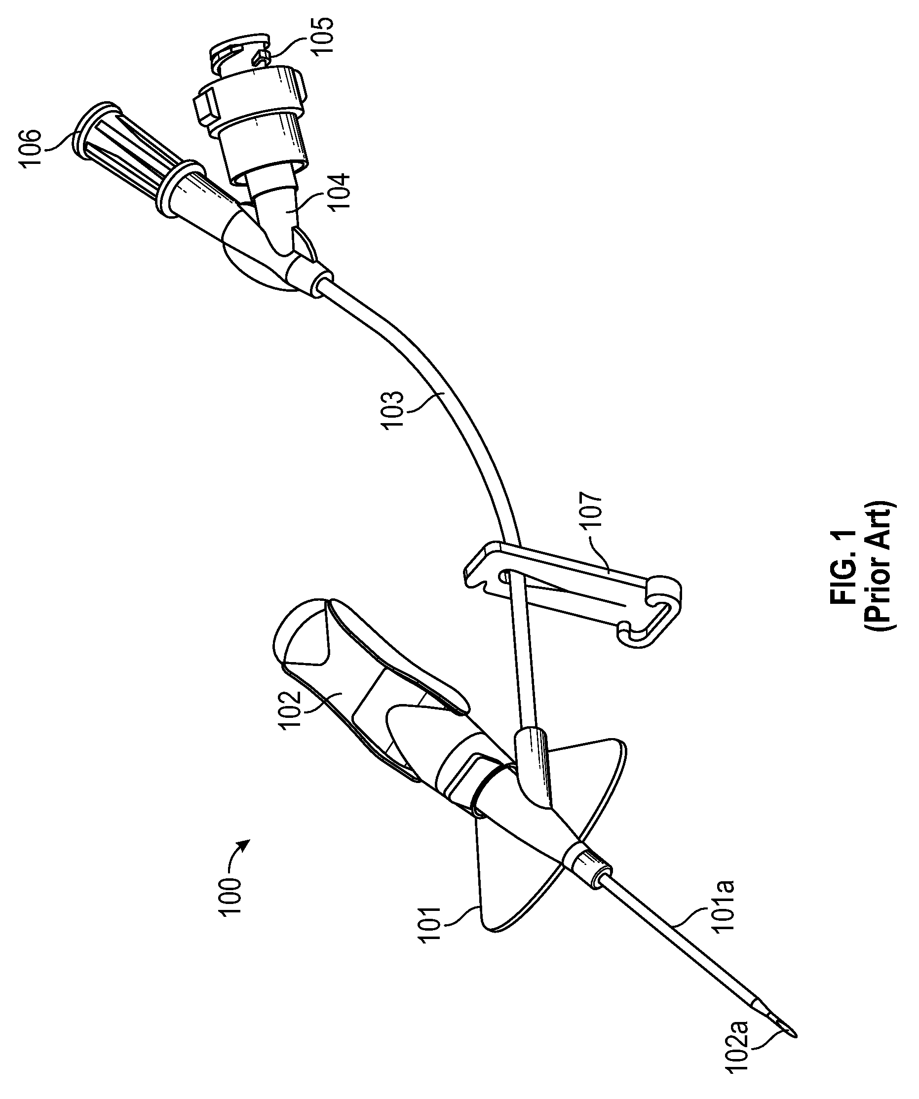
When an IV access device is identified as being "closed" or "integrated," it generally refers to the fact that the device is configured to prevent blood from escaping the device during insertion of the catheter. Typically, such IV access devices accomplish this by integrating an extension set with the catheter adapter.
FIG. 1 illustrates an example of a PRIOR ART closed IV access device 100. Device 100 includes a catheter adapter 101 from which a catheter 101a extends, a needle hub 102 from which a needle 102a extends, an extension tube 103 that is coupled to catheter adapter 101 at one end and includes a Y-adapter 104 coupled to the other end, and a clamp 107 for blocking or limiting fluid flow through extension tube 103. Y-adapter 104 includes a port 105 and a vent plug 106. Device 100 can be a closed system by incorporating fluid flow blocking components (e.g., a septum or vent) into each external opening of the device such as into a proximal end of catheter adapter 101 and into any ports in adapter 104.
Oftentimes, when using an IV access device such as access device 100, the clinician will grip catheter adapter 101 and/or needle hub 102 with the thumb on top and one or more fingers underneath. Also, if catheter adapter 101 includes a stabilization platform, such as is shown in FIG. 1, the clinician may grip a portion of the stabilization platform opposite extension tube 103. When this type of insertion technique is employed, it is difficult to position catheter adapter 101 at a low angle with respect to the patient's skin--something that is desirable to do to obtain proper placement of catheter 101a--since the clinician's fingers prevent catheter adapter 101 from being positioned close to the patient's skin.
To minimize the angle of insertion while gripping the stabilization platform of catheter adapter 101, a clinician may rotate catheter adapter 101 in a counter-clockwise direction (from the perspective of the clinician) thereby creating a space between the stabilization platform and the patient's skin within which the clinician's fingers may be positioned during insertion. However, rotating catheter adapter 101 in this manner will cause the other side of the stabilization platform, including extension tube 103, to be angled into the patient's skin. In such cases, the stabilization platform and extension tube may drag against or catch on the patient's skin thereby making a smooth insertion difficult.
BRIEF SUMMARY OF THE INVENTION
The present invention is generally directed to an IV access device that includes a needle hub having an angled paddle grip to facilitate insertion of the catheter at a low angle. The angled paddle grip can also minimize any interference that the extension tube or stabilization platform may cause during insertion. By employing an angled paddle grip, the catheter can be inserted while maintaining the stabilization platform in an orientation that is substantially parallel to the patient's skin. Also, because the extension tube runs parallel with the stabilization platform, the extension tube will not be extending into the patient's skin during insertion. This will prevent the extension tube from catching on the patient's skin or otherwise inhibiting a smooth insertion of the catheter.
A catheter adapter in accordance with the present invention can include a stabilization platform (e.g., wings) that may form a surface that can lay flat on the patient's skin. This stabilization platform can be flexible or otherwise repositionable to allow at least one side of the stabilization platform to be oriented at an angle during insertion of the catheter. To orient the stabilization platform at an angle, the needle hub can include an angled paddle grip that is designed to be positioned below the stabilization platform when the needle hub is coupled to the catheter adapter. Due to the flexibility or repositionability of the stabilization platform, the angled paddle grip will lift the stabilization platform to position it at a corresponding angle. The clinician may then grip the angled paddle grip and the angled stabilization platform when inserting the catheter. Due to the angling of these components, the catheter adapter can be maintained in a generally flat orientation during insertion. More particularly, the stabilization platform opposite the angled paddle grip as well as the extension tube will be maintained in a generally flat orientation during insertion thereby minimizing any likelihood that these components will drag against or snag on the patient's skin.
In one embodiment, the present invention is implemented as an IV access device that includes a catheter adapter from which a catheter extends distally, the catheter adapter including a wing; and a needle hub from which a needle extends distally, the needle hub being configured to be coupled to the catheter adapter such that the needle extends through the catheter. The needle hub further includes a paddle grip that is configured to be positioned adjacent the wing when the needle hub is coupled to the catheter adapter, the paddle grip being oriented at an angle.
In another embodiment, the present invention is implemented as an IV access device that includes a catheter adapter from which a catheter extends distally, the catheter adapter including a wing; and a needle hub from which a needle extends distally, the needle hub being configured to be coupled to the catheter adapter such that the needle extends through the catheter. The needle hub further includes a paddle grip that is configured to be positioned adjacent the wing when the needle hub is coupled to the catheter adapter. When the paddle grip is forced into contact with the wing, the paddle grip causes the wing to be elevated into an angled orientation.
In another embodiment, the present invention is implemented as an IV access device comprising a catheter adapter from which a catheter extends distally, the catheter adapter including a first wing that extends from a first side of the catheter adapter and a second wing that extends from a second side of the catheter adapter opposite the first side; an extension tube that couples to the catheter adapter on the second side; and a needle hub from which a needle extends distally. The needle hub is configured to be coupled to the catheter adapter such that the needle extends through the catheter. The needle hub includes a paddle grip that is configured to be positioned adjacent the first wing when the needle hub is coupled to the catheter adapter. The paddle grip causing the first wing to be positioned in an angled orientation.
These and other features and advantages of the present invention may be incorporated into certain embodiments of the invention and will become more fully apparent from the following description and appended claims, or may be learned by the practice of the invention as set forth hereinafter. The present invention does not require that all the advantageous features and all the advantages described herein be incorporated into every embodiment of the invention.
BRIEF DESCRIPTION OF THE SEVERAL VIEWS OF THE DRAWINGS
In order that the manner in which the above-recited and other features and advantages of the invention are obtained will be readily understood, a more particular description of the invention briefly described above will be rendered by reference to specific embodiments thereof that are illustrated in the appended drawings. These drawings depict only typical embodiments of the invention and are not therefore to be considered to limit the scope of the invention.
FIG. 1 illustrates a PRIOR ART IV access device.
FIG. 2 illustrates an IV access device in accordance with one or more embodiments of the present invention.
FIG. 3A illustrates a view of the catheter adapter of FIG. 2 separated from the needle hub.
FIG. 3B illustrates a view of the catheter adapter of FIG. 2 when the needle hub is coupled to the catheter adapter.
FIGS. 4A-4E illustrate various views of another access device configured in accordance with one or more embodiments of the present invention.
FIGS. 5A and 5B illustrate various views of another access device configured in accordance with one or more embodiments of the present invention.
FIGS. 6A and 6B illustrate various views of another access device configured in accordance with one or more embodiments of the present invention.
FIGS. 7A and 7B illustrate various views of another access device configured in accordance with one or more embodiments of the present invention.
DETAILED DESCRIPTION OF THE INVENTION
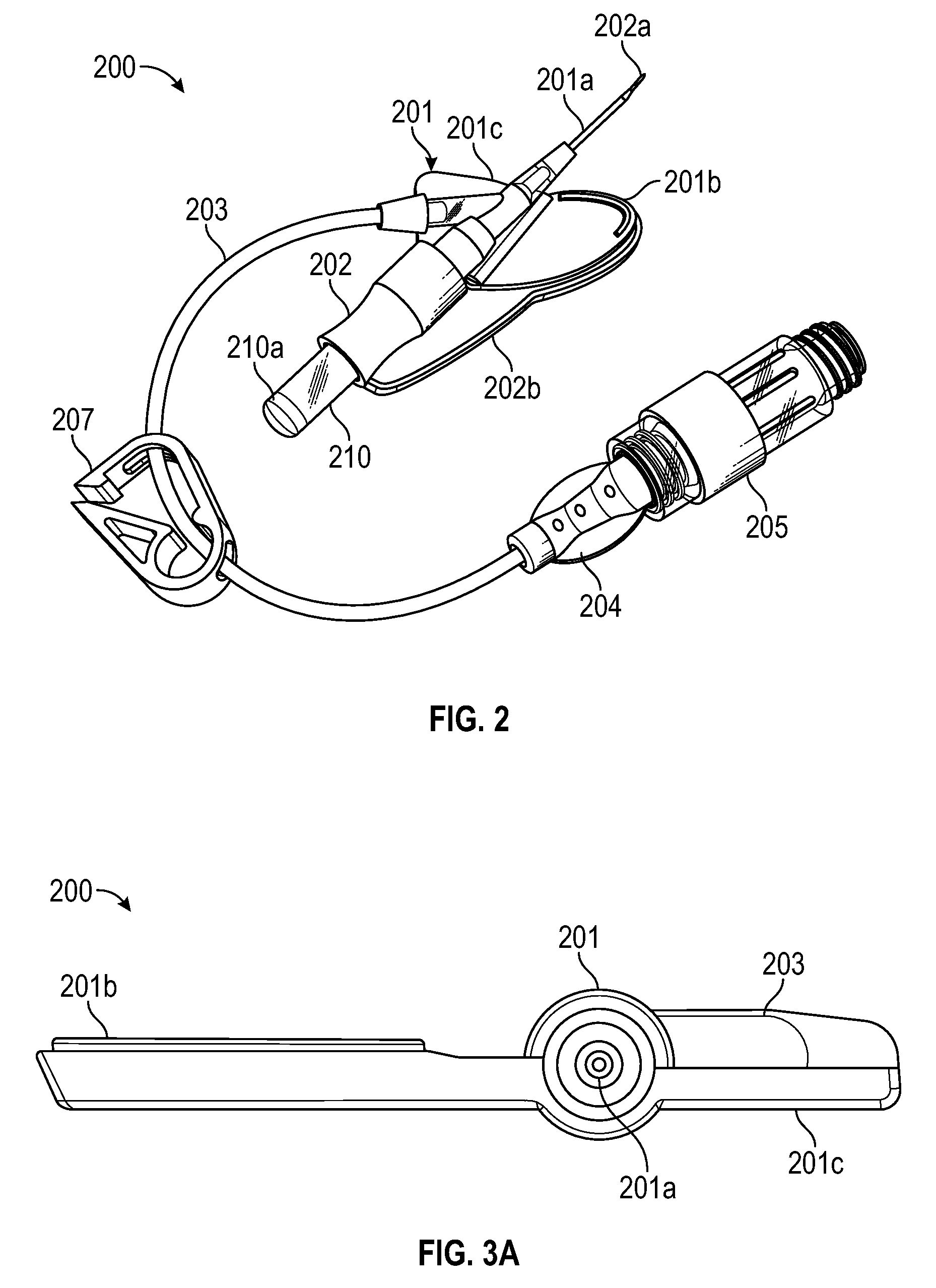
FIG. 2 illustrates an example of a closed IV access device 200 that is configured in accordance with one or more embodiments of the present invention. Access device 200 includes a catheter adapter 201 from which a catheter 201a extends distally, a needle hub 202 from which a needle 202a extends distally, an extension tube 203 that is fluidly coupled to a lumen of catheter adapter 201, and a clamp 207 for restricting the flow of fluid through extension tube 203. A luer adapter 204 or other type of adapter can be coupled to the end of extension tube 203. Also, a luer access device 205, such as one that includes a septum, may be coupled to luer adapter 204.
Catheter adapter 201 can include a stabilization platform formed by wings 201b and 201c which extend outwardly from opposite sides of catheter adapter 201. As shown in FIG. 2, access device 200 is configured for right-hand use in that extension tube 203 couples to the left side of catheter adapter 201 such that wing 201b is fully exposed. This can facilitate gripping wing 201b with the thumb of the right hand. As shown, extension tube 203 can run substantially parallel with wing 201c.
Needle hub 202 includes a paddle grip 202b that extends outwardly from the right side of needle hub 202 and has a shape that generally corresponds to the shape of wing 201b. Accordingly, paddle grip 202b can be positioned directly beneath wing 201b so that wing 201b and paddle grip 202b can be sandwiched between the clinician's thumb and index finger during insertion of catheter 201a. Alternatively, paddle grip 202b could be configured to be positioned above or otherwise adjacent to wing 201b. By configuring paddle grip 202b in this manner, the clinician can easily withdraw needle hub 202 from catheter adapter 201 by simply sliding the index finger backwards with respect to the thumb thereby causing the paddle grip 202b to slide backward away from wing 201b.
In some embodiments, needle hub 202 may also include a flash chamber 210 that is coupled to the proximal end of needle hub 202. Flash chamber 210 can include a plug 210a that allows air to escape through a proximal opening in needle hub 202 while preventing blood from escaping. Also, a proximal end of needle 202a can extend into flash chamber 210 and can include an opening to allow blood to flow out of needle 202a and into flash chamber 210.
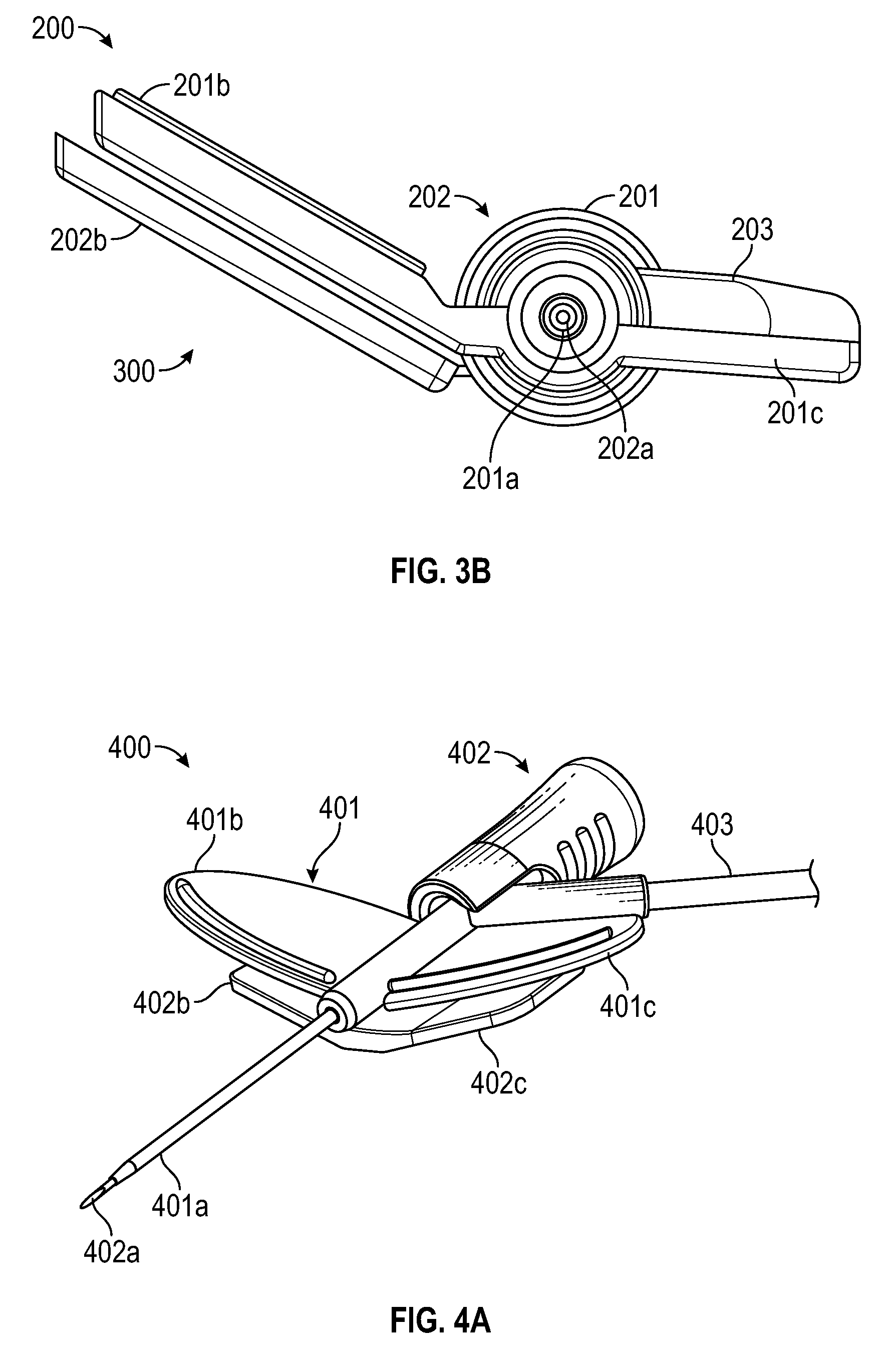
In accordance with embodiments of the present invention, and as shown in FIGS. 3A and 3B, paddle grip 202b can be angled with respect to a flat orientation of catheter adapter 201. FIG. 3A illustrates catheter adapter 201 when needle hub 202 is not coupled thereto. As shown, wings 201b and 201c are configured to lay flat (e.g., within the same plane) to form a stabilization platform on the patient's skin. Extension tube 203 is also shown as extending substantially in parallel with wing 201c. In fact, in access device 200, the interface between extension tube 203 and catheter adapter 201 is formed into wing 201c.
In contrast, FIG. 3B illustrates the orientation of wing 201b when needle hub 202 is coupled to catheter adapter 201. Paddle grip 202b can be oriented at an angle to the flat orientation of wing 201b so that, when paddle grip 202b is positioned underneath and in contact with wing 201b, paddle grip 202b lifts wing 201b into the angled orientation depicted in FIG. 3B. Importantly, with wing 201b in this angled orientation, wing 201c remains in its flat orientation. The space 300 that is created underneath wing 201b and paddle grip 202b allows the clinician to position his or her fingers underneath paddle grip 202b while still maintaining catheter adapter 201 in its flat orientation.
More particularly, the clinician may place his or her thumb on top of wing 201b and one or more of his or her fingers under paddle grip 202b during insertion of catheter 201a while still maintaining catheter adapter 201 at a low angle with respect to the patient's skin and without having to rotate catheter adapter to cause wing 201c and extension tube 203 to extend towards the patient's skin. In this way, the angled paddle grip 202b can facilitate a smooth insertion of catheter 201a at a low angle.
After the catheter has been properly placed in a patient's vein, needle hub 202 can be withdrawn from catheter adapter 201. Withdrawing needle hub 202 will likewise cause paddle grip 202b to be withdrawn such that it no longer supports wing 201b in the angled orientation. As a result, wing 201b can return to its flat orientation to facilitate securing catheter adapter 201 against the patient's skin. Accordingly, the design of access device 200 facilitates inserting catheter 201a at a low angle while still allowing catheter adapter 201 to be secured comfortably to the patient's skin.
FIGS. 3A and 3B depict an embodiment where wing 201b is formed of a flexible material that allows it to be positioned in the angled orientation. In some embodiments, a flexible material of the present invention comprises a hardness of from approximately 30 Shore A to approximately 90 Shore D. In some embodiments, a flexible material comprises a durometer hardness of from approximately 50 Shore A to approximately 90 Shore D. In some embodiments, wing 201c may be formed of the same or similar flexible material as wing 201b. In other embodiments, wing 201b (and possibly wing 201c) may be coupled to catheter adapter 201 via a hinged connection that allows the wing to pivot between the flat orientation and the angled orientation. A hinged connection may be preferred when wing 201b and/or wing 201c is formed of a rigid or semi-rigid material. In some cases, the flexibility of a wing may be created by forming a thin section within the wing. For example, a portion of the wing that extends along the length of the catheter adapter may be thinner than other portions of the wing so that the wing is allowed to bend along the thinner portion.
As indicated above, FIGS. 2, 3A, and 3B depict an access device that is designed for right-handed insertion. By inverting the depicted design, an access device configured for left-handed insertion would be formed. Also, even though the invention has primarily been described with reference to an access device that includes an extension tube (e.g., a closed or integrated device), an angled paddle grip could be employed with any type of catheter adapter having a stabilization platform consisting of at least one wing including those that do not include an extension tube.
In some embodiments, a needle hub may be configured to include two paddle grips for positioning both wings at an angled orientation. FIGS. 4A-4E and 5A-5B illustrate examples of such a two paddle grip configuration.
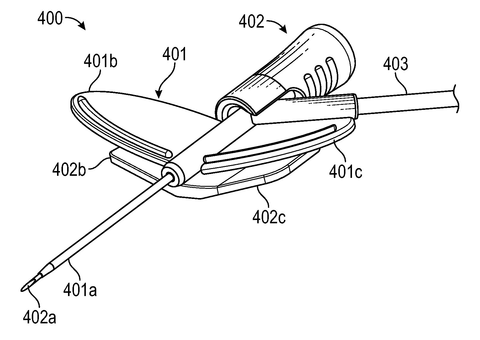
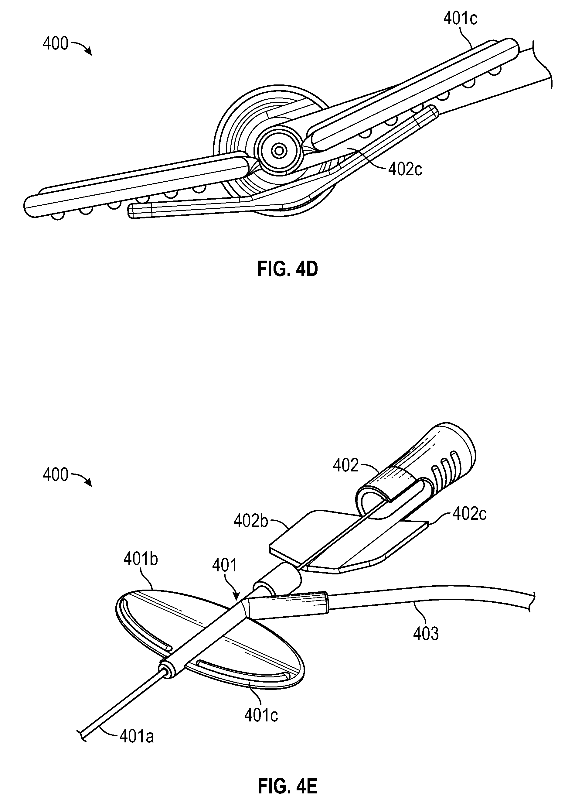
In FIG. 4A, an access device 400 similar to access device 200 is depicted. Access device 400 includes a catheter adapter 401 having a catheter 401a, a needle hub 402 that secures a needle 402a, and an extension tube 403 that extends from catheter adapter 401. Catheter adapter 401 includes two wings 401b and 401c that extend from opposite sides of catheter adapter 401. Both wings 401b and 401c are flexible to allow them to be positioned in an angled orientation. Needle hub 402 includes two paddle grips 402b and 402c that are configured to be positioned underneath wings 401b and 401c respectively when needle hub 402 is coupled to catheter adapter 401.
As best shown in FIG. 4B, paddle grips 402b and 402c are oriented at an angle so that wings 401b and 401c are lifted into a corresponding angled orientation. By orienting both wings 401b and 401c at an angle, catheter 401a can more easily be inserted at a low angle. For example, as represented in FIG. 4C, if a right-handed user were to grip paddle grip 402b and wing 401b, the user could rotate catheter adapter 401 slightly in a counterclockwise direction without causing wing 401c to be extended towards the patient's skin. In other words, by angling wing 401c in addition to wing 401b, more space can be created underneath wing 401b and paddle grip 402b to accommodate the user's fingers without having to increase the angle of insertion and while still maintaining wing 401c in a generally parallel orientation with respect to the patient's skin. Similarly, as represented in FIG. 4D, a left-handed user could grip wing 401c and paddle grip 402c during insertion and rotate catheter adapter 401 in a clockwise direction without causing wing 401b to be extended into the patient's skin.
After catheter 401a has been inserted into the patient's vasculature, needle hub 400 can be withdrawn from catheter adapter 401 as shown in FIG. 4E. With needle hub 400 withdrawn, wings 401b and 401c can return to their flat orientation (e.g., an orientation within a common plane) and secured to the patient (e.g., via tape).
FIGS. 5A and 5B illustrate an access device 500 that is substantially similar to access device 400. Access device 500 includes a catheter adapter 501 having a catheter 501a and wings 501b and 501c, a needle hub 502 having paddle grips 502b and 502c, and an extension tube 503. Paddle grips 502b and 502c can function in a similar manner as paddle grips 402b and 402c. However, as best shown in FIG. 5A, paddle grips 502b and 502c are shaped in a similar manner as wings 501b and 501c. In contrast, as best shown in FIGS. 4A and 4B, paddle grips 402b and 402c are shorter than wings 401b and 401c, only extending outwardly about half the distance that wings 401b and 401c extend.
It is noted that although the configuration of needle hub 400 and needle hub 500 are different than the configuration of needle hub 200, needle hub 200 may also be configured to include a second paddle grip similar to and opposite paddle grip 202b. In such cases, needle hub 200 could function as described above to position wings 201b and 201c in an angled orientation.
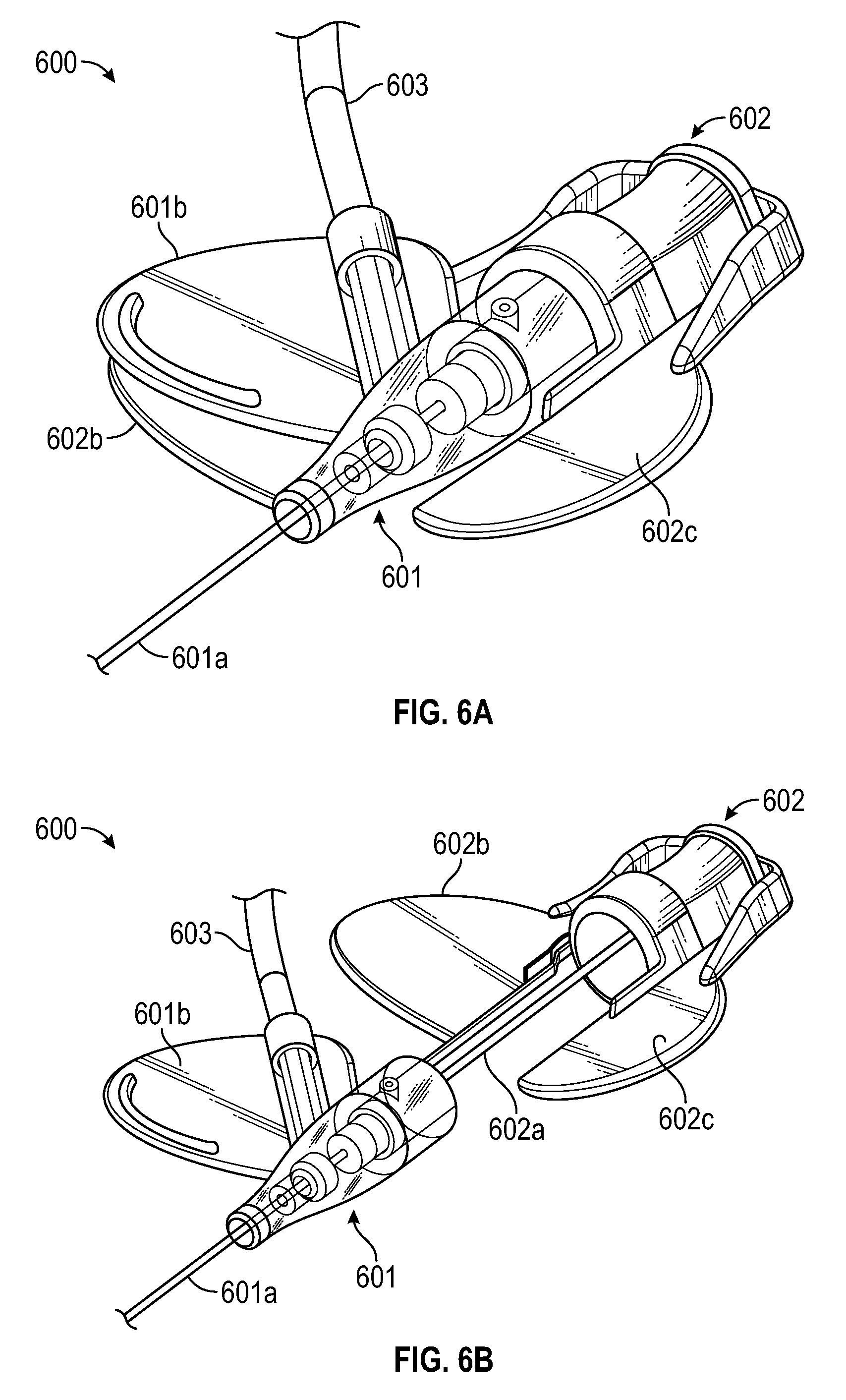
In some embodiments, a needle hub may include a paddle grip even though the catheter adapter may not have a corresponding wing. FIGS. 6A and 6B illustrate an example of an access device 600 that is configured in this manner. In FIG. 6A, needle hub 602 is shown as being coupled to catheter adapter 601 while in FIG. 6B needle hub 602 is shown as being decoupled from catheter adapter 601.
Catheter adapter 601 includes a catheter 601a and a single wing 601b that extends outwardly from a right side of the catheter adapter. An interface for coupling an extension tube 603 to catheter adapter 601 is formed within wing 601b. Although catheter adapter 601 includes only a single wing 601b, needle hub 602, from which needle 602a extends, includes paddle grips 602b and 602c that are configured to be positioned on opposite sides of catheter adapter 601 when needle hub 602 is coupled to catheter adapter 601. Paddle grip 602b generally corresponds to the shape of wing 601b and is angled such that it lifts wing 601b into an angled orientation. Paddle grip 602c may be configured in a flat orientation or in an angled orientation (e.g., as with paddle grip 402c and 502c). By including paddle grip 602c, the clinician has the option of positioning catheter adapter 601 in the orientation shown in FIG. 6B or of rotating catheter adapter 601 with respect to needle hub 602 so that wing 601b is adjacent wing 602c. Rotating catheter adapter 601 in this manner would allow the clinician to grip access device 600 on the left side (as opposed to on the right side when catheter adapter 601 is positioned as shown in FIG. 6A) during insertion of catheter 601a.
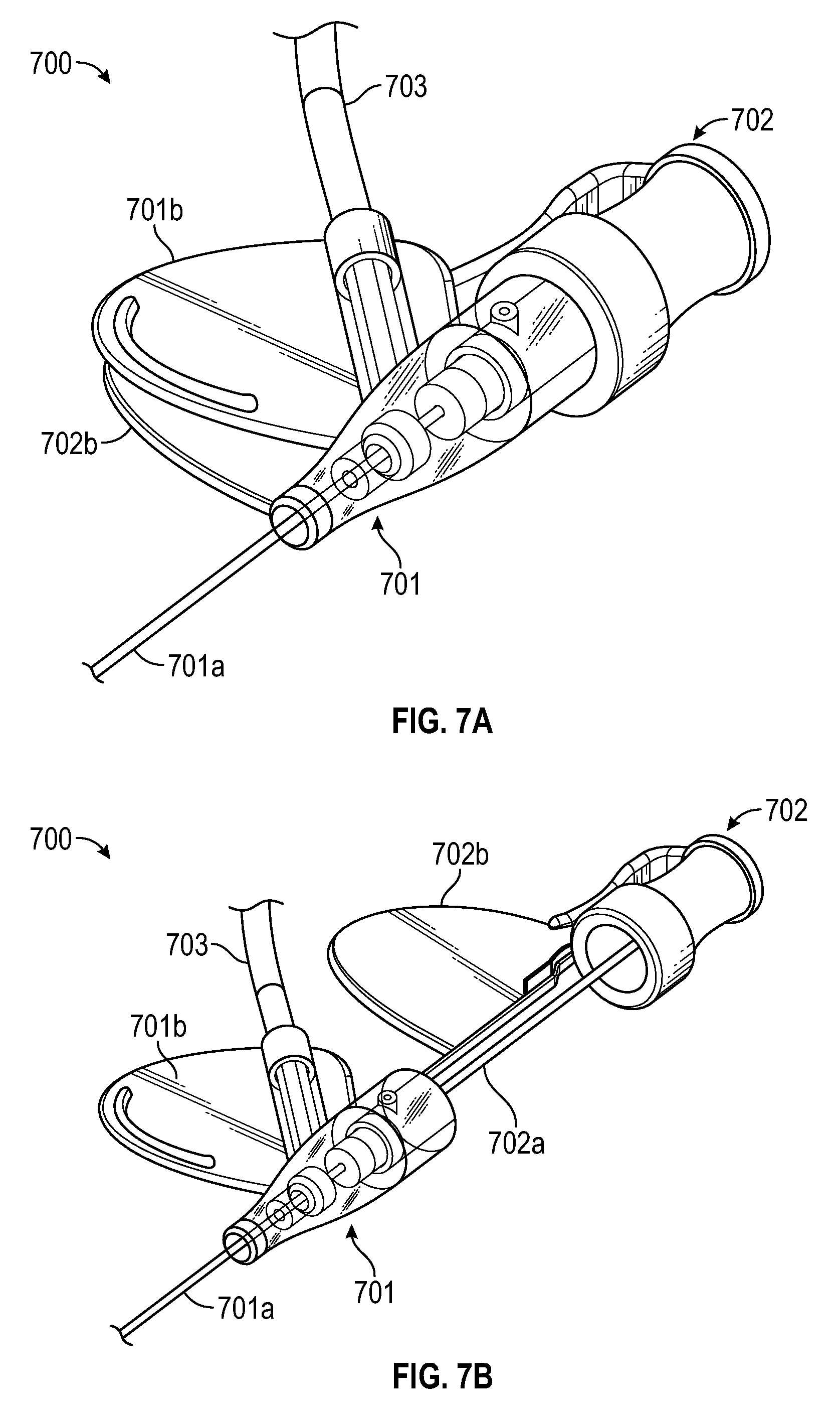
FIGS. 7A and 7B illustrate an access device 700 that includes a single paddle grip and a single wing on the same side as the extension tubing. Access device 700 includes a catheter adapter 701 from which a catheter 701a extends distally. Catheter adapter 701 also includes a wing 701b and extension tubing 703 that extends from catheter adapter 701 on the same side as wing 701b. Access device 700 also includes a needle hub 702 from which a needle 702a extends distally and a paddle grip 702b that is oriented at an angle so that wing 701b can also be oriented at an angle when paddle grip 702b is positioned adjacent (e.g., under) wing 701b. Access device 700 is therefore similar to access device 600 except that needle hub 702 does not include a second wing similar to wing 602c. Although not depicted, it is possible that access device 700 could be configured such that extension tubing 703 couples to catheter adapter 701 on a side opposite wing 701b.
In summary, the present invention is generally directed to access devices that include needle hubs having one or more angled paddle grips for positioning one or more wings of a catheter adapter's stabilization platform in an angled orientation. By positioning a wing in an angled orientation, the insertion of the catheter at a low angle is facilitated.
Various embodiments of the present invention further comprise a safety mechanism configured to secure the sharpened, distal tip of the introducer needle following removal and separation of the needle hub from the catheter adapter. A safety mechanism may include any compatible device known in the art. In some instances, the safety mechanism is configured to interact with a needle feature, such as a ferrule, notch, crimp or bump on the cannula. The crimp or bump formed in the cannula causes a slight out of round configuration that can be used to activate a safety mechanism. In some instance, the safety mechanism comprises an arm or lever that is actuated to capture the needle tip within the mechanism and prevent the tip from emerging prior to safe disposal.
The safety mechanism is attached to the body of the needle and is capable of sliding along the length thereof. In some instances, an initial or assembled position of the safety mechanism is located in proximity to the base or proximal end of the catheter adapter prior to catheterization. For some configurations, the assembled position of the safety mechanism is between the proximal end of the needle hub and the proximal end of the catheter adapter or stabilization platform, wherein the safety mechanism does not overlap the catheter adapter or stabilization platform. In some instances, a portion of the safety mechanism is positioned within the catheter adapter, with the balance of the safety mechanism being positioned external to the catheter adapter, such as within the needle hub. In some embodiments, a portion of the catheter adapter or stabilization platform is extended proximally to provide a housing in which at least a portion of the safety mechanism is housed. In some instances, the entire safety mechanism is housed within the housing of the catheter adapter or stabilization platform prior to catheterization.
In some embodiments, the assembled position of the safety mechanism positions the proximal end of the catheter adapter between the distal end of the safety mechanism and a distal end of a paddle grip of the needle hub. In some instances, the assembled position of the safety mechanism positions the proximal end of the catheter adapter between the distal end of the safety mechanism and a proximal end of a paddle grip of the needle hub. In some instances, a portion of the safety mechanism overlaps a portion of a paddle grip of the needle hub. In some embodiments, at least some portion of at least one of the catheter adapter and the paddle grip overlaps at least some portion of the safety mechanism. In some embodiments, no portion of the catheter adapter or paddle grip overlaps any portion of the safety mechanism.
In some embodiments, a defeatable mechanical connection is provided between the safety mechanism and at least one other component of the access device. In some embodiments, a distal end of the safety mechanism is selectively coupled to a proximal end of the catheter adapter. In one embodiment, the safety mechanism interlocks internally to the proximal end of the catheter adapter. In one embodiment, the safety mechanism interlocks externally to the proximal end of the catheter adapter. In some embodiments, a distal end of the safety mechanism is selectively coupled to a proximal end of the stabilization platform. In some embodiments, a surface of the safety mechanism is selectively coupled to at least one surface of at least one of the catheter adapter, a blood control valve, an extension tube, and the stabilization platform. In some instances, the mechanical connection is defeated upon securement of the needle tip within the safety mechanism.
The present invention may be embodied in other specific forms without departing from its structures, methods, or other essential characteristics as broadly described herein and claimed hereinafter. The described embodiments are to be considered in all respects only as illustrative, and not restrictive. The scope of the invention is, therefore, indicated by the appended claims, rather than by the foregoing description. All changes that come within the meaning and range of equivalency of the claims are to be embraced within their scope.
* * * * *
D00000
D00001
D00002
D00003
D00004
D00005
D00006
D00007
D00008
XML
uspto.report is an independent third-party trademark research tool that is not affiliated, endorsed, or sponsored by the United States Patent and Trademark Office (USPTO) or any other governmental organization. The information provided by uspto.report is based on publicly available data at the time of writing and is intended for informational purposes only.
While we strive to provide accurate and up-to-date information, we do not guarantee the accuracy, completeness, reliability, or suitability of the information displayed on this site. The use of this site is at your own risk. Any reliance you place on such information is therefore strictly at your own risk.
All official trademark data, including owner information, should be verified by visiting the official USPTO website at www.uspto.gov. This site is not intended to replace professional legal advice and should not be used as a substitute for consulting with a legal professional who is knowledgeable about trademark law.