Optical sensor for measuring physiological properties
McCombie , et al. July 23, 2
U.S. patent number 10,357,187 [Application Number 13/399,586] was granted by the patent office on 2019-07-23 for optical sensor for measuring physiological properties. This patent grant is currently assigned to SOTERA WIRELESS, INC.. The grantee listed for this patent is Scott Clear, Marshall Dhillon, Julian Groeli, Devin McCombie, Jim Moon, Gunnar Trommer. Invention is credited to Scott Clear, Marshall Dhillon, Julian Groeli, Devin McCombie, Jim Moon, Gunnar Trommer.


| United States Patent | 10,357,187 |
| McCombie , et al. | July 23, 2019 |
Optical sensor for measuring physiological properties
Abstract
The invention provides a physiological probe that comfortably attaches to the base of the patient's thumb, thereby freeing up their fingers for conventional activities in a hospital, such as reading and eating. The probe, which comprises a separate cradle module and sensor module, secures to the thumb and measures time-dependent signals corresponding to LEDs operating near 660 and 905 nm. The cradle module, which contains elements subject to wear, is preferably provided as a disposable unit.
| Inventors: | McCombie; Devin (San Diego, CA), Trommer; Gunnar (Encinitas, CA), Moon; Jim (Portland, OR), Dhillon; Marshall (San Diego, CA), Clear; Scott (Escondido, CA), Groeli; Julian (San Diego, CA) | ||||||||||
|---|---|---|---|---|---|---|---|---|---|---|---|
| Applicant: |
|
||||||||||
| Assignee: | SOTERA WIRELESS, INC. (San
Diego, CA) |
||||||||||
| Family ID: | 46672958 | ||||||||||
| Appl. No.: | 13/399,586 | ||||||||||
| Filed: | February 17, 2012 |
Prior Publication Data
| Document Identifier | Publication Date | |
|---|---|---|
| US 20130046159 A1 | Feb 21, 2013 | |
Related U.S. Patent Documents
| Application Number | Filing Date | Patent Number | Issue Date | ||
|---|---|---|---|---|---|
| 61444320 | Feb 18, 2011 | ||||
| Current U.S. Class: | 1/1 |
| Current CPC Class: | A61B 5/6826 (20130101); A61B 5/14552 (20130101); A61B 2562/146 (20130101); A61B 2560/0443 (20130101); A61B 5/6838 (20130101) |
| Current International Class: | A61B 5/1455 (20060101); A61B 5/00 (20060101) |
| Field of Search: | ;600/309-344 |
References Cited [Referenced By]
U.S. Patent Documents
| 4263918 | April 1981 | Swearingen et al. |
| 4270547 | June 1981 | Steffen et al. |
| 4305400 | December 1981 | Logan |
| 4367752 | January 1983 | Jimenez et al. |
| 4577639 | March 1986 | Simon et al. |
| 4582068 | April 1986 | Phillipps et al. |
| 4653498 | March 1987 | New, Jr. et al. |
| 4710164 | December 1987 | Levin et al. |
| 4722351 | February 1988 | Phillipps et al. |
| 4802486 | February 1989 | Goodman et al. |
| 4807638 | February 1989 | Sramek |
| 4905697 | March 1990 | Heggs et al. |
| 5025791 | June 1991 | Niwa |
| 5140990 | August 1992 | Jones et al. |
| 5190038 | March 1993 | Polson et al. |
| 5197489 | March 1993 | Conlan |
| 5247931 | September 1993 | Norwood |
| 5316008 | May 1994 | Suga et al. |
| 5339818 | August 1994 | Baker et al. |
| 5435315 | July 1995 | McPhee et al. |
| 5448991 | September 1995 | Polson et al. |
| 5465082 | November 1995 | Chaco |
| 5482036 | January 1996 | Diab et al. |
| 5485838 | January 1996 | Ukawa et al. |
| 5490505 | February 1996 | Diab et al. |
| 5515858 | May 1996 | Myllymaki |
| 5517988 | May 1996 | Gerhard |
| 5524637 | June 1996 | Erickson |
| 5549650 | August 1996 | Bornzin et al. |
| 5575284 | November 1996 | Athan et al. |
| 5577508 | November 1996 | Medero |
| 5588427 | December 1996 | Tien |
| 5593431 | January 1997 | Sheldon |
| 5632272 | May 1997 | Diab et al. |
| 5649543 | July 1997 | Hosaka et al. |
| 5680870 | October 1997 | Hood et al. |
| 5685299 | November 1997 | Diab et al. |
| 5709205 | January 1998 | Bukta |
| 5743856 | April 1998 | Oka et al. |
| 5766131 | June 1998 | Kondo et al. |
| 5769785 | June 1998 | Diab et al. |
| 5800349 | September 1998 | Isaacson et al. |
| 5820550 | October 1998 | Polson et al. |
| 5848373 | December 1998 | Delorme et al. |
| 5853370 | December 1998 | Chance et al. |
| 5857975 | January 1999 | Golub |
| 5865755 | February 1999 | Golub |
| 5865756 | February 1999 | Peel, III |
| 5873834 | February 1999 | Yanagi et al. |
| 5876353 | March 1999 | Riff |
| 5895359 | April 1999 | Peel, III |
| 5899855 | May 1999 | Brown |
| 5913827 | June 1999 | Gorman |
| 5919141 | July 1999 | Money et al. |
| 5941836 | August 1999 | Friedman |
| 5964701 | October 1999 | Asada et al. |
| 5964720 | October 1999 | Pelz |
| 5971930 | October 1999 | Elghazzawi |
| 6002952 | December 1999 | Diab et al. |
| 6011985 | January 2000 | Athan et al. |
| 6018673 | January 2000 | Chin et al. |
| 6036642 | March 2000 | Diab et al. |
| 6041783 | March 2000 | Gruenke |
| 6057758 | May 2000 | Dempsey et al. |
| 6067462 | May 2000 | Diab et al. |
| 6081735 | June 2000 | Diab et al. |
| 6081742 | June 2000 | Amano et al. |
| 6094592 | July 2000 | Yorkey et al. |
| 6117077 | September 2000 | Del Mar et al. |
| 6129686 | October 2000 | Friedman |
| 6157850 | December 2000 | Diab et al. |
| 6159147 | December 2000 | Lichter et al. |
| 6160478 | December 2000 | Jacobsen et al. |
| 6168569 | January 2001 | McEwen et al. |
| 6176831 | January 2001 | Voss et al. |
| 6198394 | March 2001 | Jacobsen et al. |
| 6198951 | March 2001 | Kosuda et al. |
| 6199550 | March 2001 | Wiesmann et al. |
| 6206830 | March 2001 | Diab et al. |
| 6236872 | May 2001 | Diab et al. |
| 6251080 | June 2001 | Henkin et al. |
| 6261247 | July 2001 | Ishikawa et al. |
| 6262769 | July 2001 | Anderson et al. |
| 6263222 | July 2001 | Diab et al. |
| 6287262 | September 2001 | Amano et al. |
| 6322516 | November 2001 | Masuda et al. |
| 6334065 | December 2001 | Al-Ali et al. |
| 6371921 | April 2002 | Caro et al. |
| 6388240 | May 2002 | Schulz et al. |
| RE37852 | September 2002 | Aso et al. |
| 6443890 | September 2002 | Schulze et al. |
| 6480729 | November 2002 | Stone |
| 6491647 | December 2002 | Bridger et al. |
| 6503206 | January 2003 | Li et al. |
| 6514218 | February 2003 | Yamamoto |
| 6516289 | February 2003 | David |
| 6526310 | February 2003 | Carter et al. |
| 6527729 | March 2003 | Turcott |
| 6541756 | April 2003 | Schulz et al. |
| 6544173 | April 2003 | West et al. |
| 6544174 | April 2003 | West et al. |
| 6546267 | April 2003 | Sugiura et al. |
| 6551252 | April 2003 | Sackner et al. |
| 6584336 | June 2003 | Ali et al. |
| 6589170 | July 2003 | Flach et al. |
| 6595929 | July 2003 | Stivoric et al. |
| 6605038 | August 2003 | Teller et al. |
| 6606993 | August 2003 | Wiesmann et al. |
| 6616606 | September 2003 | Petersen et al. |
| 6645154 | November 2003 | Oka |
| 6650917 | November 2003 | Diab et al. |
| 6684090 | January 2004 | Ali et al. |
| 6694177 | February 2004 | Eggers et al. |
| 6699194 | March 2004 | Diab et al. |
| 6732064 | May 2004 | Kadtke et al. |
| 6745060 | June 2004 | Diab et al. |
| 6770028 | August 2004 | Ali et al. |
| 6790178 | September 2004 | Mault et al. |
| 6811538 | November 2004 | Westbrook et al. |
| 6845256 | January 2005 | Chin et al. |
| 6850787 | February 2005 | Weber et al. |
| 6879850 | April 2005 | Kimball |
| 6893396 | May 2005 | Schulze et al. |
| 6912414 | June 2005 | Tong |
| 6934571 | August 2005 | Wiesmann et al. |
| 6947781 | September 2005 | Asada et al. |
| 6976958 | December 2005 | Quy |
| 6985078 | January 2006 | Suzuki et al. |
| 6997882 | February 2006 | Parker et al. |
| 7020508 | March 2006 | Stivoric et al. |
| 7020578 | March 2006 | Sorensen et al. |
| 7029447 | April 2006 | Rantala |
| 7041060 | May 2006 | Flaherty et al. |
| 7048687 | May 2006 | Reuss et al. |
| 7115824 | October 2006 | Lo |
| 7156809 | January 2007 | Quy |
| 7184809 | February 2007 | Sterling et al. |
| 7186966 | March 2007 | Al-Ali |
| 7194293 | March 2007 | Baker, Jr. |
| 7215984 | May 2007 | Diab et al. |
| 7215987 | May 2007 | Sterling et al. |
| 7225007 | May 2007 | Al-Ali et al. |
| 7237446 | July 2007 | Chan et al. |
| 7241265 | July 2007 | Cummings et al. |
| 7257438 | August 2007 | Kinast |
| 7296312 | November 2007 | Menkedick et al. |
| 7299159 | November 2007 | Nanikashvili |
| 7301451 | November 2007 | Hastings |
| 7314451 | January 2008 | Halperin et al. |
| 7351206 | April 2008 | Suzuki et al. |
| 7355512 | April 2008 | Al-Ali |
| 7373191 | May 2008 | Delonzer et al. |
| 7373912 | May 2008 | Self et al. |
| 7377794 | May 2008 | Al-Ali et al. |
| 7382247 | June 2008 | Welch et al. |
| 7383069 | June 2008 | Ruchti et al. |
| 7383070 | June 2008 | Diab et al. |
| 7384398 | June 2008 | Gagnadre et al. |
| 7400919 | July 2008 | Petersen et al. |
| 7412272 | August 2008 | Medina |
| 7420472 | September 2008 | Tran |
| 7427926 | September 2008 | Sinclair et al. |
| 7455643 | November 2008 | Li et al. |
| 7468036 | December 2008 | Rulkov et al. |
| 7477143 | January 2009 | Albert |
| 7479890 | January 2009 | Lehrman et al. |
| 7485095 | February 2009 | Shusterman |
| 7502643 | March 2009 | Farringdon et al. |
| 7508307 | March 2009 | Albert |
| 7509131 | March 2009 | Krumm et al. |
| 7509154 | March 2009 | Diab et al. |
| 7522035 | April 2009 | Albert |
| 7530949 | May 2009 | Al-Ali et al. |
| 7539532 | May 2009 | Tran |
| 7541939 | June 2009 | Zadesky et al. |
| 7542878 | June 2009 | Nanikashvili |
| 7586418 | September 2009 | Cuddihy et al. |
| 7598878 | October 2009 | Goldreich |
| 7602301 | October 2009 | Stirling et al. |
| 7616110 | November 2009 | Crump et al. |
| 7625344 | December 2009 | Brady et al. |
| 7628071 | December 2009 | Sasaki et al. |
| 7628730 | December 2009 | Watterson et al. |
| 7641614 | January 2010 | Asada et al. |
| 7648463 | January 2010 | Elhag et al. |
| 7656287 | February 2010 | Albert et al. |
| 7668588 | February 2010 | Kovacs |
| 7670295 | March 2010 | Sackner et al. |
| 7674230 | March 2010 | Reisfeld |
| 7674231 | March 2010 | McCombie et al. |
| 7678061 | March 2010 | Lee et al. |
| 7684954 | March 2010 | Shahabdeen et al. |
| 7689437 | March 2010 | Teller et al. |
| 7698101 | April 2010 | Alten et al. |
| 7698830 | April 2010 | Townsend et al. |
| 7698941 | April 2010 | Sasaki et al. |
| 7715984 | May 2010 | Ramakrishnan et al. |
| 7725147 | May 2010 | Li et al. |
| 7782189 | August 2010 | Spoonhower et al. |
| 7827011 | November 2010 | Devaul et al. |
| 7925022 | April 2011 | Jung et al. |
| 7976480 | July 2011 | Grajales et al. |
| 7983933 | July 2011 | Karkanias et al. |
| 8047998 | November 2011 | Kolluri et al. |
| 8082160 | December 2011 | Collins, Jr. et al. |
| 8137270 | March 2012 | Keenan et al. |
| 8167800 | May 2012 | Ouchi et al. |
| 2001/0004234 | June 2001 | Petelenz et al. |
| 2001/0007923 | July 2001 | Yamamoto |
| 2001/0013826 | August 2001 | Ahmed et al. |
| 2002/0013517 | January 2002 | West et al. |
| 2002/0032386 | March 2002 | Sackner et al. |
| 2002/0072859 | June 2002 | Kajimoto et al. |
| 2002/0151805 | October 2002 | Sugo et al. |
| 2002/0156354 | October 2002 | Larson |
| 2002/0170193 | November 2002 | Townsend et al. |
| 2002/0183627 | December 2002 | Nishii et al. |
| 2002/0193671 | December 2002 | Ciurczak et al. |
| 2002/0193692 | December 2002 | Inukai et al. |
| 2002/0198679 | December 2002 | Victor et al. |
| 2003/0004420 | January 2003 | Narimatsu |
| 2003/0130590 | July 2003 | Bui et al. |
| 2003/0135099 | July 2003 | Al-Ali |
| 2003/0153836 | August 2003 | Gagnadre et al. |
| 2003/0158699 | August 2003 | Townsend et al. |
| 2003/0167012 | September 2003 | Friedman et al. |
| 2003/0171662 | September 2003 | O'Connor et al. |
| 2003/0181815 | September 2003 | Ebner et al. |
| 2003/0208335 | November 2003 | Unuma et al. |
| 2004/0019288 | January 2004 | Kinast |
| 2004/0030261 | February 2004 | Rantala |
| 2004/0034293 | February 2004 | Kimball |
| 2004/0034294 | February 2004 | Kimball et al. |
| 2004/0054821 | March 2004 | Warren et al. |
| 2004/0073128 | April 2004 | Hatlestad et al. |
| 2004/0077934 | April 2004 | Massad |
| 2004/0122315 | June 2004 | Krill |
| 2004/0133079 | July 2004 | Mazar et al. |
| 2004/0162466 | August 2004 | Quy |
| 2004/0162493 | August 2004 | Mills |
| 2004/0225207 | November 2004 | Bae et al. |
| 2004/0267099 | December 2004 | McMahon et al. |
| 2005/0027205 | February 2005 | Tarassenko et al. |
| 2005/0043598 | February 2005 | Goode, Jr. et al. |
| 2005/0059870 | March 2005 | Aceti |
| 2005/0070773 | March 2005 | Chin et al. |
| 2005/0075550 | April 2005 | Lindekugel |
| 2005/0113107 | May 2005 | Meunier |
| 2005/0113703 | May 2005 | Farringdon et al. |
| 2005/0119586 | June 2005 | Coyle et al. |
| 2005/0119833 | June 2005 | Nanikashvili |
| 2005/0124866 | June 2005 | Elaz et al. |
| 2005/0124903 | June 2005 | Roteliuk et al. |
| 2005/0149350 | July 2005 | Kerr et al. |
| 2005/0171444 | August 2005 | Ono et al. |
| 2005/0187796 | August 2005 | Rosenfeld et al. |
| 2005/0206518 | September 2005 | Welch et al. |
| 2005/0209511 | September 2005 | Heruth et al. |
| 2005/0228296 | October 2005 | Banet |
| 2005/0228298 | October 2005 | Banet et al. |
| 2005/0228301 | October 2005 | Banet et al. |
| 2005/0234317 | October 2005 | Kiani |
| 2005/0240087 | October 2005 | Keenan et al. |
| 2005/0261565 | November 2005 | Lane et al. |
| 2005/0261593 | November 2005 | Zhang et al. |
| 2005/0265267 | December 2005 | Hwang |
| 2005/0283088 | December 2005 | Bernstein |
| 2006/0036141 | February 2006 | Kamath et al. |
| 2006/0047215 | March 2006 | Newman et al. |
| 2006/0074321 | April 2006 | Kouchi et al. |
| 2006/0074322 | April 2006 | Nitzan |
| 2006/0128263 | June 2006 | Baird |
| 2006/0142648 | June 2006 | Banet et al. |
| 2006/0155589 | July 2006 | Lane et al. |
| 2006/0178591 | August 2006 | Hempfling |
| 2006/0200029 | September 2006 | Evans et al. |
| 2006/0252999 | November 2006 | Devaul et al. |
| 2006/0265246 | November 2006 | Hoag |
| 2006/0270949 | November 2006 | Mathie et al. |
| 2006/0271404 | November 2006 | Brown |
| 2006/0281979 | December 2006 | Kim et al. |
| 2007/0010719 | January 2007 | Huster et al. |
| 2007/0055163 | March 2007 | Asada et al. |
| 2007/0066910 | March 2007 | Inukai et al. |
| 2007/0071643 | March 2007 | Hall et al. |
| 2007/0094045 | April 2007 | Cobbs et al. |
| 2007/0118056 | May 2007 | Wang et al. |
| 2007/0129769 | June 2007 | Bourget et al. |
| 2007/0142715 | June 2007 | Banet et al. |
| 2007/0156456 | July 2007 | McGillin et al. |
| 2007/0161912 | July 2007 | Zhang et al. |
| 2007/0185393 | August 2007 | Zhou et al. |
| 2007/0188323 | August 2007 | Sinclair et al. |
| 2007/0193834 | August 2007 | Pai et al. |
| 2007/0208233 | September 2007 | Kovacs |
| 2007/0232867 | October 2007 | Hansmann |
| 2007/0237719 | October 2007 | Jones et al. |
| 2007/0244376 | October 2007 | Wang |
| 2007/0250261 | October 2007 | Soehren |
| 2007/0252853 | November 2007 | Park et al. |
| 2007/0255116 | November 2007 | Mehta et al. |
| 2007/0260487 | November 2007 | Bartfeld et al. |
| 2007/0265533 | November 2007 | Tran |
| 2007/0265880 | November 2007 | Bartfeld et al. |
| 2007/0270671 | November 2007 | Gal |
| 2007/0276261 | November 2007 | Banet et al. |
| 2007/0282208 | December 2007 | Jacobs et al. |
| 2007/0287386 | December 2007 | Agrawal et al. |
| 2007/0293770 | December 2007 | Bour et al. |
| 2007/0293781 | December 2007 | Sims et al. |
| 2008/0004500 | January 2008 | Cazares et al. |
| 2008/0004507 | January 2008 | Williams, Jr. et al. |
| 2008/0004904 | January 2008 | Tran |
| 2008/0027341 | January 2008 | Sackner et al. |
| 2008/0033255 | February 2008 | Essenpreis et al. |
| 2008/0039731 | February 2008 | McCombie et al. |
| 2008/0077027 | March 2008 | Allgeyer |
| 2008/0082001 | April 2008 | Hatlestad et al. |
| 2008/0101160 | May 2008 | Besson |
| 2008/0103405 | May 2008 | Banet et al. |
| 2008/0114220 | May 2008 | Banet et al. |
| 2008/0132106 | June 2008 | Burnes et al. |
| 2008/0139955 | June 2008 | Hansmann et al. |
| 2008/0146887 | June 2008 | Rao et al. |
| 2008/0146892 | June 2008 | Leboeuf et al. |
| 2008/0161707 | July 2008 | Farringdon et al. |
| 2008/0162496 | July 2008 | Postrel |
| 2008/0167535 | July 2008 | Stivoric et al. |
| 2008/0171927 | July 2008 | Yang et al. |
| 2008/0194918 | August 2008 | Kulik et al. |
| 2008/0195735 | August 2008 | Hodges et al. |
| 2008/0204254 | August 2008 | Kazuno |
| 2008/0208013 | August 2008 | Zhang et al. |
| 2008/0208273 | August 2008 | Owen et al. |
| 2008/0214963 | September 2008 | Guillemaud et al. |
| 2008/0221399 | September 2008 | Zhou et al. |
| 2008/0221404 | September 2008 | Tso |
| 2008/0262362 | October 2008 | Kolluri et al. |
| 2008/0275349 | November 2008 | Halperin et al. |
| 2008/0281168 | November 2008 | Gibson et al. |
| 2008/0281310 | November 2008 | Dunning et al. |
| 2008/0287751 | November 2008 | Stivoric et al. |
| 2008/0294019 | November 2008 | Tran |
| 2008/0319282 | December 2008 | Tran |
| 2008/0319327 | December 2008 | Banet et al. |
| 2009/0018408 | January 2009 | Ouchi et al. |
| 2009/0018409 | January 2009 | Banet et al. |
| 2009/0018453 | January 2009 | Banet et al. |
| 2009/0040041 | February 2009 | Janetis et al. |
| 2009/0054752 | February 2009 | Jonnalagadda et al. |
| 2009/0069642 | March 2009 | Gao et al. |
| 2009/0076363 | March 2009 | Bly et al. |
| 2009/0076397 | March 2009 | Libbus et al. |
| 2009/0076398 | March 2009 | Li et al. |
| 2009/0076405 | March 2009 | Amurthur et al. |
| 2009/0082681 | March 2009 | Yokoyama et al. |
| 2009/0112072 | April 2009 | Banet et al. |
| 2009/0112281 | April 2009 | Miyazawa et al. |
| 2009/0112630 | April 2009 | Collins, Jr. et al. |
| 2009/0118590 | May 2009 | Teller et al. |
| 2009/0118626 | May 2009 | Moon et al. |
| 2009/0131759 | May 2009 | Sims et al. |
| 2009/0187085 | July 2009 | Pav |
| 2009/0192366 | July 2009 | Mensinger et al. |
| 2009/0198139 | August 2009 | Lewicke et al. |
| 2009/0221937 | September 2009 | Smith et al. |
| 2009/0222119 | September 2009 | Plahey et al. |
| 2009/0227877 | September 2009 | Tran |
| 2009/0233770 | September 2009 | Vincent et al. |
| 2009/0259113 | October 2009 | Liu et al. |
| 2009/0262074 | October 2009 | Nasiri et al. |
| 2009/0264712 | October 2009 | Baldus et al. |
| 2009/0287067 | November 2009 | Dorogusker et al. |
| 2009/0295541 | December 2009 | Roof |
| 2009/0306485 | December 2009 | Bell |
| 2009/0306487 | December 2009 | Crowe et al. |
| 2009/0306524 | December 2009 | Muhlsteff et al. |
| 2009/0312973 | December 2009 | Hatlestad et al. |
| 2009/0318779 | December 2009 | Tran |
| 2009/0322513 | December 2009 | Hwang et al. |
| 2009/0326349 | December 2009 | McGonigle et al. |
| 2010/0010380 | January 2010 | Panken et al. |
| 2010/0030034 | February 2010 | Schulhauser et al. |
| 2010/0030085 | February 2010 | Rojas Ojeda et al. |
| 2010/0056881 | March 2010 | Libbus et al. |
| 2010/0056886 | March 2010 | Hurtubise et al. |
| 2010/0113948 | May 2010 | Yang et al. |
| 2010/0125188 | May 2010 | Schilling et al. |
| 2010/0130811 | May 2010 | Leuthardt et al. |
| 2010/0160793 | June 2010 | Lee et al. |
| 2010/0160794 | June 2010 | Banet et al. |
| 2010/0160795 | June 2010 | Banet et al. |
| 2010/0160796 | June 2010 | Banet et al. |
| 2010/0160797 | June 2010 | Banet et al. |
| 2010/0160798 | June 2010 | Banet et al. |
| 2010/0168589 | July 2010 | Banet et al. |
| 2010/0210930 | August 2010 | Saylor |
| 2010/0217099 | August 2010 | Leboeuf et al. |
| 2010/0222649 | September 2010 | Schoenberg |
| 2010/0234693 | September 2010 | Srinivasan et al. |
| 2010/0234786 | September 2010 | Fulkerson et al. |
| 2010/0241011 | September 2010 | McCombie et al. |
| 2010/0280440 | November 2010 | Skelton et al. |
| 2010/0298650 | November 2010 | Moon et al. |
| 2010/0298651 | November 2010 | Moon et al. |
| 2010/0298652 | November 2010 | McCombie et al. |
| 2010/0298653 | November 2010 | McCombie et al. |
| 2010/0298654 | November 2010 | McCombie et al. |
| 2010/0298655 | November 2010 | McCombie et al. |
| 2010/0298656 | November 2010 | McCombie et al. |
| 2010/0298657 | November 2010 | McCombie et al. |
| 2010/0298658 | November 2010 | McCombie et al. |
| 2010/0298659 | November 2010 | McCombie et al. |
| 2010/0298660 | November 2010 | McCombie et al. |
| 2010/0298661 | November 2010 | McCombie et al. |
| 2010/0312115 | December 2010 | Dentinger |
| 2010/0324384 | December 2010 | Moon et al. |
| 2010/0324385 | December 2010 | Moon et al. |
| 2010/0324386 | December 2010 | Moon et al. |
| 2010/0324387 | December 2010 | Moon et al. |
| 2010/0324388 | December 2010 | Moon et al. |
| 2010/0324389 | December 2010 | Moon et al. |
| 2010/0331640 | December 2010 | Medina |
| 2011/0066006 | March 2011 | Banet et al. |
| 2011/0066007 | March 2011 | Banet et al. |
| 2011/0066008 | March 2011 | Banet et al. |
| 2011/0066009 | March 2011 | Moon et al. |
| 2011/0066010 | March 2011 | Moon et al. |
| 2011/0066037 | March 2011 | Banet et al. |
| 2011/0066038 | March 2011 | Banet et al. |
| 2011/0066039 | March 2011 | Banet et al. |
| 2011/0066043 | March 2011 | Banet et al. |
| 2011/0066044 | March 2011 | Moon et al. |
| 2011/0066045 | March 2011 | Moon et al. |
| 2011/0066050 | March 2011 | Moon et al. |
| 2011/0066051 | March 2011 | Moon et al. |
| 2011/0066062 | March 2011 | Banet et al. |
| 2011/0070829 | March 2011 | Griffin et al. |
| 2011/0076942 | March 2011 | Taveau et al. |
| 2011/0093281 | April 2011 | Plummer et al. |
| 2011/0105862 | May 2011 | Gies et al. |
| 2011/0144456 | June 2011 | Muhlsteff et al. |
| 2011/0152632 | June 2011 | Le Neel et al. |
| 2011/0178375 | July 2011 | Forster |
| 2011/0224498 | September 2011 | Banet et al. |
| 2011/0224499 | September 2011 | Banet et al. |
| 2011/0224500 | September 2011 | Banet et al. |
| 2011/0224506 | September 2011 | Moon et al. |
| 2011/0224507 | September 2011 | Banet et al. |
| 2011/0224508 | September 2011 | Moon |
| 2011/0224556 | September 2011 | Moon et al. |
| 2011/0224557 | September 2011 | Banet et al. |
| 2011/0224564 | September 2011 | Moon et al. |
| 2011/0257489 | October 2011 | Banet et al. |
| 2011/0257551 | October 2011 | Banet et al. |
| 2011/0257552 | October 2011 | Banet et al. |
| 2011/0257554 | October 2011 | Banet et al. |
| 2011/0257555 | October 2011 | Banet et al. |
| 2011/0275907 | November 2011 | Inciardi et al. |
| 2012/0065525 | March 2012 | Douniama et al. |
| 2012/0123232 | May 2012 | Najarian et al. |
| 0443267 | Aug 1991 | EP | |||
| 0993803 | Apr 2000 | EP | |||
| 2329250 | Mar 1999 | GB | |||
| 1999032030 | Jul 1999 | WO | |||
| 2006005169 | Jan 2006 | WO | |||
| 2007024777 | Mar 2007 | WO | |||
| 2007143535 | Dec 2007 | WO | |||
| 2008037820 | Apr 2008 | WO | |||
| 2008110788 | Sep 2008 | WO | |||
| 2009009761 | Jan 2009 | WO | |||
| 2010135516 | Nov 2010 | WO | |||
| 2010135518 | Nov 2010 | WO | |||
| 2010148205 | Dec 2010 | WO | |||
| 2011032132 | Mar 2011 | WO | |||
| 2011034881 | Mar 2011 | WO | |||
| 2011082341 | Jul 2011 | WO | |||
| 2011112782 | Sep 2011 | WO | |||
| 2011133582 | Oct 2011 | WO | |||
Other References
|
Non-Final Office Action issued by the US Patent and Trademark Office dated Aug. 31, 2012 in U.S. Appl. No. 12/469,213. cited by applicant . Non-Final Office Action issued by the US Patent and Trademark Office dated Sep. 14, 2012 in U.S. Appl. No. 12/650,374. cited by applicant . Drinnan et al., Relation between heart rate and pulse transit time during paced respiration. Physiol. Meas. Aug. 2001;22(3):425-432. cited by applicant . Flash et al., The Coordination of Arm Movements: An Experimentally Confirmed Mathematical Model. J Neurosci. Jul. 1985;5(7):1688-1703. cited by applicant . Ma and Zhang, A Correlation Study on the Variabilities in Pulse Transit Time, Blood Pressure, and Heart Rate Recorded Simultaneously from Healthy Subjects. Conf Proc IEEE Eng Med Biol Soc. 2005;1:996-999. cited by applicant . Non-Final Office Action issued by the US Patent and Trademark Office dated Sep. 17, 2012 in U.S. Appl. No. 12/469,192. cited by applicant . Gallagher, Comparison of Radial and Femoral Arterial Blood Pressure in Children after Cardiopulmonary Bypass. J Clin Monit. Jul. 1985;1(3):168-171. cited by applicant . Park et al., Direct Blood Pressure Measurements in Brachial and Femoral Arteries in Children. Circulation Feb. 1970;41(2)231-237. cited by applicant . Talkowski, Quantifying Physical Activity in Community Dwelling Older Adults Using Accelerometry. University of Pittsburgh (Dissertation) 2008:1-91. cited by applicant . Non-Final Office Action issued by the US Patent and Trademark Office dated Sep. 26, 2012 in U.S. Appl. No. 12/560,104. cited by applicant . Packet Definition. The Linux Information Project Jan. 8, 2006 http://www.linfo.org/packet.html. cited by applicant . RS-232. Wikipedia Dec. 5, 2008 http:I/web.archive.org/web/20081205160754/http:/!en.wikipedia.org/wiki/RS- -232. cited by applicant . Non-Final Office Action issued by the US Patent and Trademark Office dated Oct. 9, 2012 in U.S. Appl. No. 12/762,726. cited by applicant . Final Office Action issued by the US Patent and Trademark Office dated Oct. 22, 2012 in U.S. Appl. No. 12/762,822. cited by applicant . Final Office Action issued by the US Patent and Trademark Office dated Oct. 25, 2012 in U.S. Appl. No. 12/599,426. cited by applicant . Alves et al., CAN Protocol: A Laboratory Prototype for Fieldbus Applications. XIX IMEKO World Congress Fundamental and Applied Metrology Sep. 6-11, 2009, Lisbon, Portugal. 4 pages :454-457 ISBN 978-963-88410-0-1. cited by applicant . Benefits of Digital Sensors. Gems Sensors. Feb. 14, 2008. http://web.archive.org/web/20080214122230/http://www.sensorland.com/HowPa- ge054.html. cited by applicant . Final Office Action issued by the US Patent and Trademark Office dated Oct. 25, 2012 in U.S. Appl. No. 12/762,790. cited by applicant . Non-Final Office Action issued by the US Patent and Trademark Office dated Oct. 30, 2012 in U.S. Appl. No. 12/559,386. cited by applicant . Non-Final Office Action issued by the US Patent and Trademark Office dated Nov. 6, 2012 in U.S. Appl. No. 12/559,379. cited by applicant . Non-Final Office Action issued by the US Patent and Trademark Office dated Nov. 6, 2012 in U.S. Appl. No. 12/650,370. cited by applicant . Poon and Zhang, Cuff-Less and Noninvasive Measurements of Arterial Blood Pressure by Pulse Transit Time. Conf Proc IEEE Eng Med Biol Soc. 2005;6:5877-5880. cited by applicant . Non-Final Office Action issued by the US Patent and Trademark Office dated Nov. 7, 2012 in U.S. Appl. No. 12/559,392. cited by applicant . Non-Final Office Action issued by the US Patent and Trademark Office dated Jul. 18, 2012 in U.S. Appl. No. 12/650,389. cited by applicant . Chan et al., Noninvasive and Cuffless Measurements of Blood Pressure for Telemedicine. Proceedings of the 23rd Annual International Conference of the IEEE Engineering in Medicine and Biology Society 2001:3 pages. cited by applicant . Fung, Advisory System for Administration of Phenylephrine Following Spinal Anesthesia for Cesarean Section. Master's Thesis. University of British Columbia 2002: 119 pages. cited by applicant . Liu et al., The Changes in Pulse Transit Time at Specific Cuff Pressures during Inflation and Deflation. Proceedings of the 28th IEEE EMBS Annual International Conference New York City, USA, Aug. 30-Sep. 3, 2006:6404-6405. cited by applicant . Nitzan et al., Effects of External Pressure on Arteries Distal to the Cuff During Sphygmomanometry. IEEE Transactions on Biomedical Engineering, Jun. 2005;52(6):1120-1127. cited by applicant . USB 2.0 Specification Engineering Change Notice. Oct. 20, 2000. cited by applicant . Yan and Zhang, A Novel Calibration Method for Noninvasive Blood Pressure Measurement Using Pulse Transit Time. Proceedings of the 4th IEEE-EMBS International Summer School and Symposium on Medical Devices and Biosensors St Catharine's College,Cambridge, UK, Aug. 19-22, 2007. cited by applicant . Zislin et al., Ways of Improving the Accuracy of Arterial Pressure Oscillometry. Biomedical Engineering 2005;39(4):174-178. cited by applicant . International Search Report and Written Opinion dated May 29, 2012 issued in PCT/US2012/025648. cited by applicant . Non-Final Office Action issued by the US Patent and Trademark Office dated Aug. 3, 2012 in U.S. Appl. No. 12/762,925. cited by applicant . Non-Final Office Action issued by the US Patent and Trademark Office dated Aug. 3, 2012 in U.S. Appl. No. 12/762,963. cited by applicant . Non-Final Office Action issued by the US Patent and Trademark Office dated Aug. 20, 2012 in U.S. Appl. No. 12/762,777. cited by applicant . Non-Final Office Action issued by the US Patent and Trademark Office dated Aug. 21, 2012 in U.S. Appl. No. 12/469,107. cited by applicant . Non-Final Office Action issued by the US Patent and Trademark Office dated Aug. 24, 2012 in U.S. Appl. No. 12/762,936. cited by applicant . International Search Report and Written Opinion dated Jul. 22, 2011 issued in PCT/US2011/027843. cited by applicant . International Search Report and Written Opinion dated Jul. 20, 2011 issued in PCT/US2011/033100. cited by applicant . Non-Final Office Action issued by the US Patent and Trademark Office dated May 26, 2011 in U.S. Appl. No. 12/469,151. cited by applicant . Response to Non-Final Office Action dated Nov. 25, 2011 in U.S. Appl. No. 12/469,151. cited by applicant . Notice of Allowance issued by the US Patent and Trademark Office dated Feb. 1, 2012 in U.S. Appl. No. 12/469,151. cited by applicant . Non-Final Office Action issued by the US Patent and Trademark Office dated Aug. 4, 2011 in U.S. Appl. No. 12/469,182. cited by applicant . Response to Non-Final Office Action dated Nov. 25, 2011 in U.S. Appl. No. 12/469,182. cited by applicant . Notice of Allowance issued by the US Patent and Trademark Office dated Dec. 28, 2011 in U.S. Appl. No. 12/469,182. cited by applicant . International Search Report and Written Opinion dated Oct. 15, 2010 issued in PCT/US2010/035550. cited by applicant . Non-Final Office Action issued by the US Patent and Trademark Office dated Apr. 12, 2012 in U.S. Appl. No. 12/559,429. cited by applicant . Non-Final Office Action issued by the US Patent and Trademark Office dated Apr. 12, 2012 in U.S. Appl. No. 12/559,430. cited by applicant . Non-Final Office Action issued by the US Patent and Trademark Office dated Apr. 24, 2012 in U.S. Appl. No. 12/559,435. cited by applicant . Non-Final Office Action issued by the US Patent and Trademark Office dated Apr. 25, 2012 in U.S. Appl. No. 12/762,733. cited by applicant . Non-Final Office Action issued by the US Patent and Trademark Office dated Apr. 27, 2012 in U.S. Appl. No. 12/762,822. cited by applicant . Non-Final Office Action issued by the US Patent and Trademark Office dated Mar. 27, 2012 in U.S. Appl. No. 12/559,422. cited by applicant . Mathie, Monitoring and Interpreting Human Movement Patterns using a Triaxial Accelerometer. Faculty of Engineering. The University of New South Wales. PhD Dissertation. Aug. 2003: part1 pp. 1-256. cited by applicant . Mathie, Monitoring and Interpreting Human Movement Patterns using a Triaxial Accelerometer. Faculty of Engineering. The University of New South Wales. PhD Dissertation. Aug. 2003: part2 pp. 256-512. cited by applicant . International Search Report and Written Opinion dated Apr. 27, 2012 as reported in PCT/US2011/067441. cited by applicant . Non-Final Office Action issued by the US Patent and Trademark Office dated May 7, 2012 in U.S. Appl. No. 12/469,115. cited by applicant . Non-Final Office Action issued by the US Patent and Trademark Office dated May 9, 2012 in U.S. Appl. No. 12/762,836. cited by applicant . Non-Final Office Action issued by the US Patent and Trademark Office dated May 10, 2012 in U.S. Appl. No. 12/559,419. cited by applicant . Jackson, Digital Filter Design and Synthesis Using High-Level Modeling Tools. Virginia Polytechnic Institute and State University Thesis. Dec. 1999. cited by applicant . Kim et al., Two Algorithms for Detecting Respiratory Rate from ECG Signal. IFMBE Proceedings 2007;14(6) JC27:4069-4071. cited by applicant . O'Haver, Peak Finding and Measurement, Version 1.6 Oct. 26, 2006. http://web.archive.org/web/20090205162604/http://terpconnect.umd.edu/-toh- /spectrum/PeakFindingandMeasurement.htm. cited by applicant . Reinvuo et al., Measurement of Respiratory Rate with High-Resolution Accelerometer and EMFit Pressure Sensor. Proceedings of the 2006 IEEE Sensors Applications Symposium Feb. 7-9, 2006:192-195. cited by applicant . Non-Final Office Action issued by the US Patent and Trademark Office dated May 11, 2012 in U.S. Appl. No. 12/762,846. cited by applicant . Non-Final Office Action issued by the US Patent and Trademark Office dated May 11, 2012 in U.S. Appl. No. 12/762,874. cited by applicant . Non-Final Office Action issued by the US Patent and Trademark Office dated Jun. 11, 2012 in U.S. Appl. No. 12/469,222. cited by applicant . Non-Final Office Action issued by the US Patent and Trademark Office dated Jun. 8, 2012 in U.S. Appl. No. 12/650,383. cited by applicant . Non-Final Office Action issued by the US Patent and Trademark Office dated Jun. 8, 2012 in U.S. Appl. No. 12/650,392. cited by applicant . Non-Final Office Action issued by the US Patent and Trademark Office dated Jun. 20, 2012 in U.S. Appl. No. 12/762,751. cited by applicant . International Search Report and Written Opinion dated Jun. 29, 2012 issued in PCT/US2012/025640. cited by applicant . Non-Final Office Action issued by the US Patent and Trademark Office dated Jul. 5, 2012 in U.S. Appl. No. 12/560,138. cited by applicant . "Signal Strength." Oct. 6, 2008. http://web.archive.org/web/20081 006200523/http:/!en.wikipedia.org/wiki/Signal_strength. cited by applicant . Non-Final Office Action issued by the US Patent and Trademark Office dated May 24, 2012 in U.S. Appl. No. 12/560,111. cited by applicant . Restriction Requirement issued by the US Patent and Trademark Office dated Apr. 24, 2012 in U.S. Appl. No. 12/469,107. cited by applicant . Response to Restriction Requirement dated Jun. 14, 2012 in U.S. Appl. No. 12/469,107. cited by applicant . Final Office Action issued by the United States Patent and Trademark Office in U.S. Appl. No. 12/469,236 dated Jul. 8, 2013. cited by applicant . Non-Final Office Action issued by the United States Patent and Trademark Office in U.S. Appl. No. 12/560,111 dated Jul. 8, 2013. cited by applicant . Scanaill et al., A Review of Approaches to Mobility Telemonitoring of the Elderly in Their Living Environment. Annals of Biomed Engineer. Apr. 2006;34(4):547-563. cited by applicant . Notice of Allowance issued by the United States Patent and Trademark Office in U.S. Appl. No. 12/762,733 dated Jul. 24, 2013. cited by applicant . Final Office Action issued by the United States Patent and Trademark Office in application No. 12/762,944 dated Aug. 2, 2013. cited by applicant . Response to Office Action issued by the United States Patent and Trademark Office in application No. 12/559,039 dated Aug. 9, 2013. cited by applicant . Sifil et al., Evaluation of the Harmonized Alert Sensing Technology Device for Hemodynamic Monitoring in Chronic Hemodialysis Patients. ASAIO J. Nov.-Dec. 2003;49(6):667-672. cited by applicant . Weinhold et al., Buprenorphine alone and in combination with naloxone in non-dependent humans. Drug Alcohol Depend. Aug. 1992;30(3):263-274. cited by applicant . Final Office Action issued by the United States Patent and Trademark Office in application No. 12/762,726 dated Aug. 15, 2013. cited by applicant . Extended European Search Report and Written Opinion issued in application No. EP 10817733 dated Aug. 29, 2013. cited by applicant . Extended European Search Report and Written Opinion issued in application No. EP 08770884 dated Sep. 17, 2013. cited by applicant . Allen et al., Classification of a known sequence of motions and postures from accelerometry data using adapted Gaussian mixture models. Physiol. Meas. 2006;27:935-951. cited by applicant . Asada et al., Active Noise Cancellation Using MEMS Accelerometers for Motion-Tolerant Wearable Bio-Sensors. Proceedings of the 26th Annual International Conference of the IEEE EMBS. San Francisco, CA, USA. Sep. 1-5, 2004:2157-2160. cited by applicant . Bowers et al., Respiratory Rate Derived from Principal Component Analysis of Single Lead Electrocardiogram. Computers in Cardiology Conference Proceedings Sep. 2008;35:437-440. cited by applicant . Bussmann et al., Measuring daily behavior using ambulatory accelerometry: The Activity Monitor. Behav Res Methods Instrum Comput. Aug. 2001;33(3):349-356. cited by applicant . Cretikos et al., The Objective Medical Emergency Team Activation Criteria: a case-control study. Resuscitation Apr. 2007;73(1):62-72. cited by applicant . Espina et al., Wireless Body Sensor Network for Continuous Cuff-less Blood Pressure Monitoring. Proceedings of the 3rd IEEE-EMBS. International Summer School and Symposium on Medical Devices and Biosensors. MIT, Boston, USA, Sep. 4-6, 2006:11-15. cited by applicant . Fieselmann et al., Respiratory rate predicts cardiopulmonary arrest for internal medicine patients. J Gen Intern Med Jul. 1993;8(7):354-360. cited by applicant . Goldhill et al., A physiologically-based early warning score for ward patients: the association between score and outcome. Anaesthesia Jun. 2005;60(6):547-553. cited by applicant . Hung et al., Estimation of Respiratory Waveform Using an Accelerometer. 5th IEEE International Symposium on Biomedical Imaging: From Nano to Macro, May 14-17, 2008:1493-1496. cited by applicant . Jin, A Respiration Monitoring System Based on a Tri-Axial Accelerometer and an Air-Coupled Microphone. Technische Universiteit Eindhoven, University of Technology. Master's Graduation Paper, Electrical Engineering Aug. 25, 2009. cited by applicant . Karantonis et al., Implementation of a Real-Time Human Movement Classifier Using a Triaxial Accelerometer for Ambulatory Monitoring. IEEE Transactions on Information Technology in Biomedicine. Jan. 2006;10(1):156-167. cited by applicant . Khambete et al., Movement artefact rejection in impedance pneumography using six strategically placed electrodes. Physiol. Meas. 2000;21:79-88. cited by applicant . Khan et al., Accelerometer Signal-based Human Activity Recognition Using Augmented Autoregressive Model Coefficients and Artificial w Neural Nets. 30th Annual International Conference of the IEEE Engineering in Medicine and Biology Society. Aug. 20-24, 2008:5172-5175. cited by applicant . Mason, Signal Processing Methods for Non-Invasive Respiration Monitoring. Department of Engineering Science, University of Oxford 2002. cited by applicant . Mathie et al., Classification of basic daily movements using a triaxial accelerometer. Med Biol Eng Comput. Sep. 2004;42(5):679-687. cited by applicant . Otto et al., System Architecture of a Wireless Body Area Sensor Network for Ubiquitous Health Monitoring. Journal of Mobile Multimedia Jan. 10, 2006;1(4):307-326. cited by applicant . Park et al., An improved algorithm for respiration signal extraction from electrocardiogram measured by conductive textile electrodes using instantaneous frequency estimation. Med Bio Eng Comput 2008;46:147-158. cited by applicant . PDF-Pro for iPhone & iPod touch User Manual. ePapyrus Jul. 2009;1:1-25 http://epapyrus.com/en/files/PDFPro%. cited by applicant . Seo et al., Performance Improvement of Pulse Oximetry-Based Respiration Detection by Selective Mode Bandpass Filtering. Ergonomics and Health Aspects of Work with Computers Lecture Notes in Computer Science, 2007;4566:300-308. cited by applicant . Soh et al., An investigation of respiration while wearing back belts. Applied Ergonomics 1997; 28(3):189-192. cited by applicant . Subbe et al., Effect of introducing the Modified Early Warning score on clinical outcomes, cardiopulmonary arrests and intensive care utilization in acute medical admissions. Anaesthesia Aug. 2003;58(8):797-802. cited by applicant . Vuorela et al., Two portable long-term measurement devices for ECG and bioimpedance. Second International Conference on Pervasive Computing Technologies for Healthcare.. Jan. 30-Feb. 1, 2008: 169-172. cited by applicant . Wolf et al., Development of a Fall Detector and Classifier based on a Triaxial Accelerometer Demo Board. 2007:210-213. cited by applicant . Non-Final Office Action issued by the US Patent and Trademark Office dated Apr. 30, 2012 in U.S. Appl. No. 12/762,790. cited by applicant . Non-Final Office Action issued by the US Patent and Trademark Office dated Mar. 30, 2012 in U.S. Appl. No. 12/469,236. cited by applicant . Non-Final Office Action issued by the US Patent and Trademark Office dated Apr. 3, 2012 in U.S. Appl. No. 12/469,094. cited by applicant . Restriction Requirement issued by the US Patent and Trademark Office dated Feb. 2, 2012 in U.S. Appl. No. 12/469,222. cited by applicant . Non-Final Office Action issued by the US Patent and Trademark Office dated Mar. 27, 2012 in U.S. Appl. No. 12/559,426. cited by applicant . Non-Final Office Action issued by the US Patent and Trademark Office dated Apr. 3, 2012 in U.S. Appl. No. 12/559,039. cited by applicant . Non-Final Office Action issued by the US Patent and Trademark Office dated Dec. 29, 2011 in U.S. Appl. No. 12/559,080. cited by applicant . Response to Non-Final Office Action dated Mar. 19, 2012 in U.S. Appl. No. 12/559,080. cited by applicant . Notice of Allowance issued by the US Patent and Trademark Office dated Apr. 2, 2012 in U.S. Appl. No. 12/559,080. cited by applicant . Non-Final Office Action issued by the US Patent and Trademark Office dated Dec. 15, 2011 in U.S. Appl. No. 12/560,077. cited by applicant . Non-Final Office Action issued by the US Patent and Trademark Office dated Mar. 8, 2012 in U.S. Appl. No. 12/560,093. cited by applicant . Restriction Requirement issued by the US Patent and Trademark Office dated Dec. 14, 2012 in U.S. Appl. No. 12/560,093. cited by applicant . Response to Restriction Requirement dated Feb. 15, 2012 in U.S. Appl. No. 12/560,093. cited by applicant . Non-Final Office Action issued by the US Patent and Trademark Office dated Mar. 1, 2012 in U.S. Appl. No. 12/560,104. cited by applicant . Restriction Requirement issued by the US Patent and Trademark Office dated Jan. 19, 2012 in U.S. Appl. No. 12/469,115. cited by applicant . Response to Restriction Requirement dated Feb. 15, 2012 in U.S. Appl. No. 12/469,115. cited by applicant . Restriction Requirement issued by the US Patent and Trademark Office dated Nov. 14, 2011 in U.S. Appl. No. 12/469,127. cited by applicant . Response to Restriction Requirement dated Feb. 15, 2012 in U.S. Appl. No. 12/469,127. cited by applicant . Non-Final Office Action issued by the US Patent and Trademark Office dated Mar. 9, 2012 in U.S. Appl. No. 12/469,127. cited by applicant . Non-Final Office Action issued by the US Patent and Trademark Office dated Apr. 3, 2012 in U.S. Appl. No. 12/469,137. cited by applicant . International Preliminary Report on Patentability dated Dec. 1, 2011 issued in PCT/US2010/035554. cited by applicant . International Search Report and Written Opinion dated Sep. 23, 2010 issued in PCT/US2010/035554. cited by applicant . International Preliminary Report on Patentability dated Jan. 5, 2012 issued in PCT/US2010/039000. cited by applicant . International Search Report and Written Opinion dated Sep. 7, 2010 issued in PCT/US2010/039000. cited by applicant . International Search Report and Written Opinion dated Nov. 3, 2010 issued in PCT/US2010/048729. cited by applicant . International Search Report and Written Opinion dated Nov. 5, 2010 issued in PCT/US2010/048866. cited by applicant . International Search Report and Written Opinion dated Mar. 3, 2011 issued in PCT/US2010/062564. cited by applicant . Non-Final Office Action issued by the US Patent and Trademark Office dated Aug. 30, 2012 in U.S. Appl. No. 12/469,202. cited by applicant . Non-Final Office Action issued by the US Patent and Trademark Office dated Sep. 17, 2012 in U.S. Appl. No. 12/650,354. cited by applicant . Non-Final Office Action issued by the US Patent and Trademark Office dated Sep. 21, 2012 in U.S. Appl. No. 12/469,115. cited by applicant . Response to Non-Final Office Action issued in U.S. Appl. No. 12/469,236 dated Sep. 27, 2012. cited by applicant . Response to Non-Final Office Action issued in U.S. Appl. No. 12/487,283 dated Sep. 27, 2012. cited by applicant . Non-Final Office Action issued by the US Patent and Trademark Office dated Sep. 28, 2012 in U.S. Appl. No. 12/560,087. cited by applicant . Response to Non-Final Office Action issued in U.S. Appl. No. 12/762,836 dated Oct. 9, 2012. cited by applicant . Response to Non-Final Office Action issued in U.S. Appl. No. 12/559,429 dated Oct. 12, 2012. cited by applicant . Response to Non-Final Office Action issued in U.S. Appl. No. 12/559,430 dated Oct. 12, 2012. cited by applicant . Response to Non-Final Office Action issued in U.S. Appl. No. 12/559,435 dated Oct. 23, 2012. cited by applicant . Final Office Action issued by the US Patent and Trademark Office dated Oct. 24, 2012 in U.S. Appl. No. 12/599,429. cited by applicant . Final Office Action issued by the US Patent and Trademark Office dated Oct. 24, 2012 in U.S. Appl. No. 12/599,430. cited by applicant . Non-Final Office Action issued by the US Patent and Trademark Office dated Oct. 23, 2012 in U.S. Appl. No. 12/762,944. cited by applicant . Response to Non-Final Office Action issued in U.S. Appl. No. 12/762,733 dated Oct. 25, 2012. cited by applicant . Final Office Action issued by the US Patent and Trademark Office dated Oct. 26, 2012 in U.S. Appl. No. 12/762,836. cited by applicant . Non-Final Office Action issued by the US Patent and Trademark Office dated Oct. 24, 2012 in U.S. Appl. No. 12/559,403. cited by applicant . Non Final Office Action issued by the United States Patent and Trademark Office in U.S. Appl. No. 12/559,413 dated Nov. 9, 2012. cited by applicant . Response to Office Action issued in U.S. Appl. No. 12/762,846 dated Nov. 13, 2012. cited by applicant . Response to Office Action issued in U.S. Appl. No. 12/762,874 dated Nov. 13, 2012. cited by applicant . Response to Office Action issued in U.S. Appl. No. 12/560,111 dated Nov. 26, 2012. cited by applicant . Response to Office Action issued in U.S. Appl. No. 11/930,881 dated Nov. 26, 2012. cited by applicant . Final Rejection issued by the United States Patent and Trademark Office in U.S. Appl. No. 12/559,419 dated Nov. 16, 2012. cited by applicant . Non Final Office Action issued by the United States Patent and Trademark Office in U.S. Appl. No. 12/559,408 dated Nov. 23, 2012. cited by applicant . Response to Office Action issued in U.S. Appl. No. 12/138,199 dated Nov. 29, 2012. cited by applicant . Response to Office Action issued in U.S. Appl. No. 12/650,383 dated Dec. 7, 2012. cited by applicant . Response to Office Action issued in U.S. Appl. No. 12/650,392 dated Dec. 7, 2012. cited by applicant . Final Rejection issued by the United States Patent and Trademark Office in U.S. Appl. No. 12/559,435 dated Dec. 12, 2012. cited by applicant . Final Rejection issued by the United States Patent and Trademark Office in U.S. Appl. No. 12/560,111 dated Dec. 12, 2012. cited by applicant . Clifford et al., Measuring Tilt with Low-g Accelerometers. Freescale Semiconductor, Inc., 2005:8 pages. cited by applicant . McKneely et al., Plug-and-Play and Network-Capable Medical Instrumentation and Database with a Complete Healthcare Technology Suite: MediCAN. Joint Workshop on High Confidence Medical Devices, Software, and Systems and Medical Device Plug-and-Play Interoperability. 2007:122-129. cited by applicant . Montgomery et al., Lifeguard--A Personal Physiological Monitor for Extreme Environments. Conf Proc IEEE Eng Med Biol Soc. 2004;3:2192-2195. cited by applicant . Thongpithoonrat et al., Networking and Plug-and-Play of Bedside Medical Instruments. Conf Proc IEEE Eng Med Biol Soc. 2008;2008:1514-1517. cited by applicant . Yang et al., Research on Multi-Parameter Physiological Monitor Based on CAN Bus. IFMBE Proceed. 2008;19:417-419. cited by applicant . Zeltwanger, Controller Area Network and CANopen in Medical Equipment. Bus Briefing: Med Dev Manuf Technol. 2002:34-37. cited by applicant . Zitzmann and Schumann, Interoperable Medical Devices Due to Standardized CANopen Interfaces. Joint Workshop on High Confidence Medical Devices, Software, and Systems and Medical Device Plug-and-Play Interoperability. 2007:97-103. cited by applicant . Non Final Office Action issued by the United States Patent and Trademark Office in U.S. Appl. No. 13/432,976 dated Dec. 14, 2012. cited by applicant . Final Rejection issued by the United States Patent and Trademark Office in U.S. Appl. No. 12/762,733 dated Dec. 20, 2012. cited by applicant . Final Rejection issued by the United States Patent and Trademark Office in U.S. Appl. No. 12/762,846 dated Dec. 20, 2012. cited by applicant . Final Rejection issued by the United States Patent and Trademark Office in U.S. Appl. No. 12/650,392 dated Jan. 3, 2013. cited by applicant . Final Rejection issued by the United States Patent and Trademark Office in U.S. Appl. No. 12/487,283 dated Jan. 3, 2013. cited by applicant . Non Final Office Action issued by the United States Patent and Trademark Office in U.S. Appl. No. 13/292,923 dated Jan. 14, 2013. cited by applicant . Notice of Allowance issued by the United States Patent and Trademark Office in U.S. Appl. No. 11/470,708 dated Jan. 18, 2013. cited by applicant . International Search Report and Written Opinion issued in PCT/US2012/064302 dated Jan. 15, 2013. cited by applicant. |
Primary Examiner: Winakur; Eric F
Assistant Examiner: Fardanesh; Marjan
Attorney, Agent or Firm: Acuity Law Group, PC Whittaker; Michael A.
Parent Case Text
RELATED APPLICATIONS
The present application claims the benefit of priority to U.S. Provisional Application No. 61/444,320, filed Feb. 18, 2011, which is hereby incorporated by reference, including the drawings.
Claims
What is claimed is:
1. A physiological probe configured for securing to a subject's digit, comprising: a sensor module comprising (a) electronic circuitry which comprises (i) at least one source of electromagnetic radiation, and (ii) a photodetector configured to detect radiation from the at least one source of electromagnetic radiation after it has interacted with the subject's tissue, thereby acquiring data relating to at least one physiologic property of the subject, wherein the photodetector is operably connected to a connection cable for delivery of photodetector signals to an external processing unit, and (b) a flexible enclosure providing a cover for the electronic circuitry, wherein the flexible enclosure comprises (i) at least one aperture through which the at least one source of electromagnetic radiation emits radiation for irradiating the subject's tissue, (ii) at least one aperture through which the photodetector receives radiation after it has interacted with the subject's tissue, and (iii) an aperture through which the connection cable passes; and a cradle module comprising (a) at least first and second rigid housing members mated to one another via a hinge region to form an approximately semicircular ring which is configured to releasably receive the sensor module, wherein the hinge region is configured to provide, when secured to the subject's digit, a range of adjustment in a diameter of the ring while physically constraining an included angle measured between the at least one source of electromagnetic radiation and the photodetector within a predetermined range, wherein the predetermined range of the included angle measured between the source(s) of electromagnetic radiation and the photodetector is between about 60.degree. and about 30.degree..
2. A physiological probe according to claim 1, wherein the hinge is configured to accommodate a subject's thumb at the level of the proximal phalanx for purposes of acquiring the data relating to at least one physiologic property of the subject.
3. A physiological probe according to claim 1, wherein the hinge is configured to accommodate a girth of between about 6.2 cm and about 7.4 cm.
4. A physiological probe according to claim 1, wherein the hinge region is a pivoting hinge formed by mating the first and second rigid housing members, and wherein the structure of the first and second rigid housing members constrains opening or closing of the hinge beyond the predetermined range when mated to one another via the pivoting hinge.
5. A physiological probe according to claim 4, wherein, the hinge is configured such that a force applied to move the hinge beyond the predetermined range separates the first and second rigid housing members.
6. A physiological probe according to claim 1, wherein the predetermined range of the included angle measured between the source(s) of electromagnetic radiation and the photodetector is between about 55.degree. and about 35.degree..
7. A physiological probe according to claim 1, wherein the sensor module comprises one or more hinge points in the flexible enclosure.
8. A physiological probe according to claim 7, wherein the sensor module comprises at least two hinge points in the flexible enclosure configured to provide three substantially planar sensor module surfaces when the sensor module is mated to the cradle module.
9. A physiological probe according to claim 1, wherein the surface of the sensor module and the surface of the cradle module which come into contact when the two modules are mated comprise corresponding registration structures configured to register the position of the sensor module in the cradle module.
10. A physiological probe according to claim 1, wherein the length of the cradle module is between about 1 cm and about 1.5 cm.
11. A physiological probe according to claim 1, wherein the cradle module is disposable.
12. A method of obtaining pulse oximetry signals from a subject, comprising: affixing a physiological probe according to claim 1 to the palmar aspect of a digit of the subject at the level of the proximal phalanx, wherein the probe is positioned on the subject's digit such that the source(s) of electromagnetic radiation, when energized, provide irradiation of tissues of the subject through the capillary, arterial, and soft tissue of the digit, and subsequently to the photodetector; energizing the sources to irradiate the tissues of the subject; and detecting photodetector signals at an external processing unit operably connected via the connection cable.
13. A method according to claim 12, further comprising calculating one or more of a blood pressure value, an SpO2 value, a pulse rate, a respiration cycle, and a photoplethysmograph waveform for the subject using the photodetector signals.
14. A method according to claim 12, comprising determining a blood pressure value for the subject using the photodetector signals.
Description
BACKGROUND OF THE INVENTION
The following discussion of the background of the invention is merely provided to aid the reader in understanding the invention and is not admitted to describe or constitute prior art to the present invention.
The saturation of peripheral oxygen in the blood (SpO2) is sometimes referred to as the `fifth vital sign`. Medical professionals can detect hypoxemia, i.e. a deficiency of oxygen, by monitoring a patient's SpO2. Values between about 95-100% are considered normal; those below this indicate hypoxemia, and will typically trigger an alarm in a hospital setting.
A technique called pulse oximetry measures SpO2. Technically this parameter is determined from a patient's arterial oxygen saturation, or SaO2, which is a percentage of oxygenated arterial hemoglobin present in their blood. Functional hemoglobin molecules can bind with up to four oxygen molecules to yield `oxygenated` hemoglobin (HbO2). A hemoglobin molecule bound to less than four oxygen molecules is classified as `reduced` hemoglobin (Hb). Conventional pulse oximeters feature algorithms that assume only HbO2 and Hb are present in the blood, and measure SpO2 from the ratio of oxygenated hemoglobin to the total amount of hemoglobin (both oxygenated and reduced) according to equation (1):
.times..times..times..times..times..times..times..times..times..times..ti- mes..times. ##EQU00001##
HbO2 and Hb feature different absorption spectra in the visible and infrared regions, and can therefore be measured optically. Conventional pulse oximeters thus typically feature light sources (most typically light-emitting diodes, or LEDs) that radiate in the red (near 660 nm) and infrared (typically between 900-950 nm) spectral regions. A photodetector measures a portion of radiation at each wavelength that transmits through the patient's pulsating blood, but is not absorbed. At 660 nm, for example, Hb absorbs about ten times as much radiation as HbO2, whereas at 905 nm HbO2 absorbs about two times as much radiation as Hb. Detection of transmitted radiation at these wavelengths yields two time-dependent waveforms, each called a plethysmogram (PPG), that an oximeter analyzes to solve for SpO2 as defined in equation (1) above.
Specifically, the oximeter processes PPG waveforms measured with red (RED(PPG)) and infrared (IR(PPG)) wavelengths to determine time-dependent AC and DC signals. The term `AC` signals, as used herein, refers to a portion of a PPG waveform that varies relatively rapidly with time, e.g. the portion of the signal modulated by pulsations in the patient's blood. `DC` signals, in contrast, are portions of the PPG that are relatively invariant with time, e.g. the portion of the signal originating from scattering off of components such as bone, skin, and non-pulsating components of the patient's blood.
More specifically, AC signals are modulated by a heartbeat-induced pulse present in both waveforms. The pulse represents a pressure wave, launched by the heart, which propagates through the patient's vasculature and causes a time-dependent increase in volume in both arteries and capillaries. When the pressure pulse reaches vasculature irradiated by the oximeter's optical system, a temporary volumetric increase results in a relatively large optical absorption according to the Beer-Lambert Law. Typically only about 0.5-1% of the total signal measured by the photodetector originates from the AC signal, with the remainder originating from the DC signal. Separation of AC and DC signals is typically done with both analog and digital filtering techniques that are well-known in the art.
During pulse oximetry a normalized `r` value is typically calculated from AC and DC signals using equation (2), below:
.times..times..function..times..times..function..times..times..function..- times..times..function. ##EQU00002## r, which is sometimes called a `ratio of ratios` (RoR), represents a ratio of Hb to HbO2. It equates an actual SpO2 value, which ranges from 0-100% O2, to an empirical relationship that resembles a non-linear equation. Above about 70% O2 this equation typically yields values that are accurate to a few percent. Measurements below this value, while not necessarily accurate, still indicate a hypoxic patient in need of medical attention.
Like SpO2, continuous noninvasive blood pressure ("cNIBP") monitoring relies on accurate measurement of PPG and ACC waveforms obtained from a pulse oximeter, together with an electrocardiogram waveform (ECG). cNIBP is typically measured with the `Composite Technique`, which is described in detail in the co-pending patent applications entitled: VITAL SIGN MONITOR FOR MEASURING BLOOD PRESSURE USING OPTICAL, ELECTRICAL, AND PRESSURE WAVEFORMS (U.S. Ser. No. 12/138,194; filed Jun. 12, 2008 and published as 20090018453A1), and BODY-WORN SYSTEM FOR MEASURING CONTINUOUS NON-INVASIVE BLOOD PRESSURE (cNIBP) (U.S. Ser. No. 12/650,354, filed Nov. 15, 2009 and published as 20100168589A1), the contents of which are fully incorporated herein by reference.
As described therein, the Composite Technique (or, alternatively, the `Hybrid Technique` referred to therein) typically uses a single PPG waveform from the SpO2 measurement (typically the IR(PPG) waveform, as this typically has a better signal-to-noise ratio than the RED(PPG) waveform), along with the ECG waveform, to calculate a parameter called `pulse transit time` (PTT) which strongly correlates to blood pressure. Specifically, the ECG waveform features a sharply peaked QRS complex that indicates depolarization of the heart's left ventricle, and, informally, provides a time-dependent marker of a heart beat. PTT is the time separating the peak of the QRS complex and the onset, or `foot`, of the RED/IR(PPG) waveforms; it is typically a few hundred milliseconds. The QRS complex, along with the foot of each pulse in the RED/IR(PPG), can be used to more accurately extract AC signals using a mathematical technique described in detail below. In certain embodiments, both the RED/IR(PPG) waveforms may be collectively processed to enhance the accuracy of the cNIBP measurement.
Typical pulse oximeters feature a probe encased in a clothespin-shaped housing that includes both red and infrared LEDs, and a photodetector that detects radiation from the LEDs after it passes through a portion of the patient's body. The probe typically clips to a patient's index finger. Most probes operate in a transmission-mode optical geometry, and relay analog waveforms measured by LEDs and the photodetector to an external processing unit. Because it is based on an optical measurement, pulse oximetry can be extremely sensitive to a patient's motion. Activities such as walking, finger tapping, falling, and convulsing can result in a number of artifacts that distort both the AC and DC components of waveforms measured with the oximeter's optical system. Motion-related activities, for example, can cause the oximeter probe to move relative to the patient's finger, change the amount of ambient light that irradiates the photodetector, and disrupt both arterial and venus blood flow in vasculature measured by the optical system. Each of these events can generate artifacts that, in some cases, are similar to the AC and DC signals within the PPG waveforms. Ultimately this can cause the pulse oximeter to generate inaccurate values and false alarms.
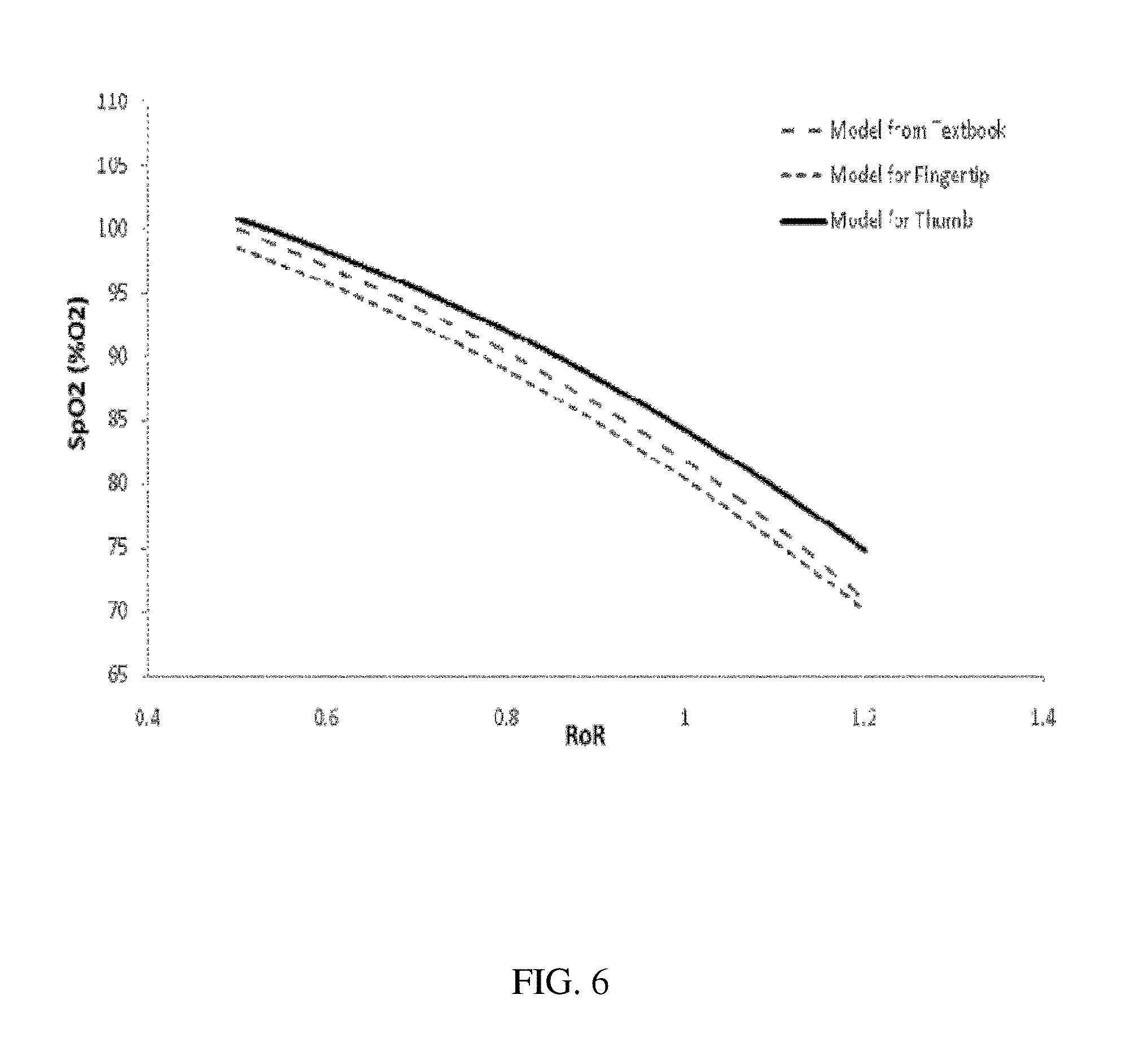
International Patent Application No. PCT/US2010/039000, which is hereby incorporated by reference in its entirety, describes a physiological probe that comfortably clips to the base of the patient's thumb, thereby freeing up their fingers for conventional activities in a hospital, such as reading and eating. The probe reversibly secures to the thumb with, e.g., an easy-to-use Velcro strap, disposable tape, or similar closure, or may be provided in the form of a closed ring which slips over the thumb. It measures time-dependent waveforms (RED/IR(PPG)) corresponding to LEDs typically operating near 660 nm and 905 nm. Clinically accurate pulse oximetry measurements made at the base of the patient's thumb require a set of coefficients relating r (from Eq. 2) to SpO2 that are typically determined with a set of empirical experiments (e.g. a `breathe down` study, described below). These coefficients differ from those used in conventional oximetry measurements because of the differences between vasculature in the base of the thumb and the tip of the index finger. Typically the base of the thumb features relatively fewer capillary beds, and thus the coefficients are preferably adjusted accordingly.
It is to be understood that the invention is not limited in its application to the details of construction and to the arrangements of the components set forth in the following description or illustrated in the drawings. The invention is capable of embodiments in addition to those described and of being practiced and carried out in various ways. Also, it is to be understood that the phraseology and terminology employed herein, as well as the abstract, are for the purpose of description and should not be regarded as limiting.
As such, those skilled in the art will appreciate that the conception upon which this disclosure is based may readily be utilized as a basis for the designing of other structures, methods and systems for carrying out the several purposes of the present invention. It is important, therefore, that the claims be regarded as including such equivalent constructions insofar as they do not depart from the spirit and scope of the present invention.
SUMMARY OF THE INVENTION
It is an object of the present invention to provide a physiological probe having at least one emitter and an associated detector configured to attach to a tissue site, where the detector is configured to measure a detector signal responsive to the intensity of energy from the emitter after it has interacted with a tissue site. These physiological probes, which are well suited to function as pulse oximeter probes as described hereinafter, are configured for securing to a digit of the subject, and most preferably to a subject's thumb at the level of a proximal phalanx.
In particular, the physiological probe of the present invention comprises a sensor module and a cradle module. In various aspects, the present invention relates to the individual components of the probe, to the probe itself, and to methods of its manufacture and use.
The sensor module comprises: (a) a electronic circuitry, which in certain embodiments takes the form of a flexible circuit board, which comprises (i) one or more, and preferably at least two sources of electromagnetic radiation, and (ii) a photodetector configured to detect the radiation from the source(s) which has passed through or been reflected by the subject's tissue, thereby acquiring data relating to at least the oxygen saturation level of blood of the subject, wherein the photodetector is operably connected to a connection cable for delivery of photodetector signals to an external processing unit; and (b) a flexible enclosure providing a cover for the circuit board, wherein the flexible enclosure comprises (i) at least one aperture through which the source(s) emit radiation for irradiating the subject's tissue, (ii) at least one aperture through which the photodetector receives radiation which has interacted with (e.g., passed through and/or been reflected by) the subject's tissue, and (iii) an aperture through which the connection cable passes.
The cradle module comprises: at least first and second rigid housing members mated to one another via a hinge region to form an approximately semicircular ring which is configured to reversibly receive the sensor module; that is, in use the sensor module is releasably attached to the cradle module.
Optionally, the physiological probe of the present invention further comprises a retainer attached to the cradle module and configured to reversibly attach the physiological probe to the digit of the subject, for example by wrapping around the entire circumference of the digit.
As used herein, the term "releasably attached" refers to two separate modules which may be engaged with and disengaged from one another in the course of normal use. In certain embodiments, the hinge region is configured to provide a range of adjustment in the diameter of the ring while physically constraining the included angle measured between the sources and the photodetector within a predetermined range. As used herein, the term "semicircular ring" is not meant to refer to the geometric shape forming an arc of constant radius extending through 180 degrees. Rather, the term refers to a shape which fits circumferentially around a portion of, but not the complete circumference of, a digit as depicted, for example, in FIG. 4.
As noted, the hinge region provides a range of adjustment in the diameter of the semicircular ring formed by the cradle, thereby allowing the physiological probe to adjust to a range of different digit girths. In certain embodiments meant to be compatible with the human thumb, the hinge of an adult-sized cradle is preferably designed to accommodate a girth of between about 6.2 cm and about 7.4 cm, with pediatric sizes or sizes for other (smaller) digits being made appropriately smaller. At the same time, it is important for proper functioning that the geometry of the radiation sources and the photodetector be maintained within an acceptable range for proper function of the sensor.
In one example, the hinge region may be a pivoting joint in which a pin on one rigid housing member fits into a corresponding hole on the other rigid housing member. Alternatively, the hinge region may simply be a flexible region which bridges the two rigid housing members. Other types of hinge arrangements will be apparent to the skilled artisan. When desired, the angular constraint can be accomplished by providing "stops" in one or both of the first and second rigid housing members which prevent opening or closing of the hinge past the predetermined range. Preferably, the predetermined range of the included angle measured between the sources and the photodetector are less than or equal to about 60.degree., and more preferably between about 60.degree. and about 30.degree., and most preferably between about 55.degree. and about 35.degree.. The term "about" in the context of this patent application refers to +/-10% of a given measurement.
The cradle module is preferably designed as a disposable component which receives a sensor module preferably designed for multiple uses. As used herein, the term "disposable" with regard to the cradle refers to the characteristic that the cradle module may be disengaged from sensor module in the course of normal use by the user of the physiological probe such that the sensor module may be easily separated from, and need not be discarded with, the cradle. This can serve to place the device components of the physiological probe most susceptible to wear and cleanability issues on a disposable unit, while retaining the more expensive electronic components on an easily cleanable and reusable unit. In certain embodiments, the hinge is configured such that a force may be applied to move the hinge past one or more of its "stops," thereby separating the first and second rigid housing members and preventing improper reuse. This can also facilitate removal of the sensor module for its reuse. In certain embodiments, the sensor module can be rendered cleanable for reuse by sealing of the apertures positioned proximal to the radiation source(s) and the detector with a material providing sufficient transparency to the appropriate wavelengths being employed in the device.
When the sensor module is mated to the cradle, the sensor module substantially conforms to the semicircular ring shape created by the cradle. As used herein, the term "substantially conforms" refers to a module which fits into the designed shape of another module in a manner which permits the two modules to function as a unit in the intended fashion. To facilitate this conformal fit, the sensor module may comprise one or more flexible hinge regions, (e.g., one or more living hinges molded into the flexible enclosure).
In certain embodiments, the surface of the sensor module and the surface of the cradle module which come into contact when the two modules are mated comprise corresponding registration structures, e.g., a ridge structure on one module which inserts into a corresponding dimple structure on the other module; a tab on one module which fits into a corresponding slot on the other module. The term "registration" as used herein refers to the act of adjusting or aligning the parts of a device in relation to each other. These corresponding registration structures can help to ensure proper placement of the sensor module into the cradle module. The combination of a rigid cradle housing and careful registration of components helps to maintain a consistent orientation of the optical components in the probe and improves the consistency of the optical path through the artery and capillary tissue, while maintaining comfort through the use of relatively soft and flexible materials on the sensor module.
In preferred embodiments, the sensor module comprises at least two flexible hinge points, such that mating of the sensor module to the cradle creates three substantially planar sensor module surfaces. A first planar surface comprises the radiation sources; a middle planar surface provides a flat base surface to engage the thumb tissue of the subject; and a third planar surface comprises the photodetector. These substantially planar surfaces can serve to improve pressure application to the underlying arteries, thereby helping to increase signal amplitudes and maintain a consistent light path.
In certain embodiments, the length of the cradle module is less than the average length of the desired proximal phalanx. In the case of an adult-sized thumb, the cradle may be about 1 cm to 1.5 cm in length, with pediatric sizes being made appropriately smaller. The term "about" in this context refers to +/-10% of a given measurement.
The radiation sources preferably emit radiation at about 660 nm and about 905 nm wavelengths. Preferably, the radiation sources are proximal to one another, and most preferably contained within the same electronic package. In proper use, the physiological probe is placed on the palmar aspect of the digit, preferably the thumb. The present invention can provide a consistent optical path from the radiation sources, through the princeps pollicis artery and soft tissue below the proximal phalanx, and subsequently to the photodetector.
Still other embodiments are found in the following detailed description of the invention, and in the claims.
BRIEF DESCRIPTION OF THE DRAWINGS
FIG. 1 shows a three-dimensional mechanical drawing of an exemplary cradle module for use as a component of a physiological probe, designed to function as a pulse oximeter probe, of the present invention.
FIG. 2 shows a three-dimensional mechanical drawing of an exemplary sensor module for use as a component of a physiological probe, designed to function as a pulse oximeter probe, of the present invention.
FIG. 3 shows a photograph of a distal end of the sensor module of FIG. 2 which includes a pair of light sources and a photodetector.
FIGS. 4A-B show three-dimensional mechanical drawings of the cradle module of FIG. 1 attached to a flexible material configured to wrap around a patient's thumb and housing the sensor module of FIG. 2.
FIG. 4C shows a two-dimensional mechanical drawing of the cradle module of FIG. 1 housing the sensor module of FIG. 2.
FIG. 5 is a series of mechanical drawings depicting how the sensor module of FIG. 2 inserts into the cradle module of FIG. 1 to form an exemplary physiological probe.
FIG. 6 shows a graph depicting a relationship between SpO2 and a `ratio of ratios` (RoR) for measurements from theoretical model in a medical textbook, made from the tip of a patient's index finger, and made from the base of a patient's thumb.
DETAILED DESCRIPTION OF THE INVENTION
FIGS. 1-4 depict components of a semicircular physiologic probe 100 comprising a separate sensor module 101 and cradle module 102 which mate to one another. The probe is designed to be comfortably worn for extended periods (e.g. several days) while freeing up the patient's fingers for activities such as reading and eating that are commonplace in, e.g., a hospital. While described in detail as a pulse oximeter probe, the physiological probes of the present invention are applicable to any similar device having at least one emitter and an associated detector configured to attach to a tissue site.
The cradle module 102 is shaped as a semicircular ring that wraps around a base of patient's digit to measure time-dependent waveforms (PPG) that can be used, e.g., in the determination of SpO2 and cNIBP. The cradle module 102 is comprised of two substantially rigid members 103, 104 connected by a hinge 105. The rigid members 103, 104 may be made out of a number of materials known in the art such as plastics, metals, and the like; for example, polypropylene, acrylates (PMMA, SMMA, etc.), styrenes (SAN, PS, ASA, ABS, etc.), polycarbonate, copolymers, ionomer resins (Surlyn), polyamides, polyesters, thermoplastic elastomers, aluminum, brass, nickel, etc. A preferred example is Eastman Tritan.TM. copolyester. The length of the cradle module is less than the average length of the proximal phalanx so as not to interfere with bending of the digit at the joint. An optimal length for an adult-sized cradle configured for attachment to a thumb is in the range of 1 cm to 1.5 cm.
A portion of each rigid member lying below the hinge location by providing points of interfering physical contact between the two rigid members which act as stops to constrain the opening and closing of the hinge within a predetermined range. This serves two purposes. First, the hinge 105 provides a range of adjustment in the diameter of the opening in the semicircular ring which fits over the digit, thereby allowing the physiological probe to adjust to a range of different finger sizes. In certain embodiments, the hinge of an adult-sized cradle is preferably designed to accommodate a thumb diameter of about 1.8-2.3 cm, or a girth of between about 6.2 cm and about 7.4 cm. Second, to increase the amount of radiation that passes through the artery and capillaries in the tissue, and thereby optimize signal quality, the cradle acts to maintain the LEDs 106, 107 and photodiode 108 at an included angle (.theta.) of approximately 35-55 degrees. As shown in FIG. 4C, the `included angle .theta.` refers to the angle formed between a first line drawn parallel to the planar surface comprising the radiation source and a second line drawn parallel to the planar surface comprising the photodetector. Optical components separated at this angle tend to increase the relative contribution of signal coming from the artery; ultimately this improves the accuracy of the cNIBP measurement, as PTT values measured from arterial components correlate better to blood pressure than those measured from capillary components.
The probe makes a transmission-mode optical measurement along an inner portion of the digit with the pair of embedded LEDs 106, 107 operating at, respectively, 660 and 905 nm, and a single photodetector 108 that detects these wavelengths after they pass through vasculature and other tissue lying beneath the LEDs. Preferably, both LEDs and the photodetector are positioned to measure blood pulsing in portions of the princeps pollicis artery, which is the principal artery of the thumb and stems from the radial artery. Measuring blood flowing in this artery enhances the accuracy of a PTT-based measurements of blood pressure, as is described in more detail in VITAL SIGN MONITOR FOR MEASURING BLOOD PRESSURE USING OPTICAL, ELECTRICAL, AND PRESSURE WAVEFORMS (U.S. Ser. No. 12/138,194; filed Jun. 12, 2008 and published as 20090018453A1), and BODY-WORN SYSTEM FOR MEASURING CONTINUOUS NON-INVASIVE BLOOD PRESSURE (cNIBP) (U.S. Ser. No. 12/650,354, filed Nov. 15, 2009 and published as 20100168589A1), the contents of which have been previously incorporated by reference.
Electronic circuitry providing the LEDs and photodetector may be provided in the form of a small flexible circuit board 109 in the sensor module, which may additionally include, for example, a trans-impedance amplifier for amplifying photocurrent from the photodetector and converting it into a corresponding voltage. The electronic circuitry can also include a resistor that identifies specific wavelengths emitted by the LEDs; these wavelengths, in turn, influence values of correlation coefficients that relate RoR to SpO2, as described below. In other embodiments, the flexible circuit board 109 can be replaced with a series of insulated wires that connect the LEDs, photodetector, trans-impedance amplifier, and other components to form a circuit.
A flexible housing 110 covers and protects the flexible circuit board 109. The flexible housing 110 may preferably be formed from any water and alcohol-resistant material, with materials having a durometer (A) in the range of 25 to 60 (e.g., HTV, RTV, or LSR elastomers, etc.) providing an optimum combination of comfort and sufficient resistance to compression to allow the probe to apply pressure to the underlying arteries. A particularly preferred material has a durometer (A) of about 40, such as Nusil MED-4044 silicone elastomer. For purposes of manufacturing, the circuit board may be inserted into the housing through a slit-like opening 115 at the top, which may then be sealed, for example with a liquid silicone elastomeric material. A connection cable 116 extends through an opening 117 at the bottom of the housing.
The housing features rectangular openings 111 and 112 through which the LEDs emit, and the photodetector receives, radiation. In certain embodiments a filter may be provided over the photodetector in order to both seal the aperture and filter undesired ambient light frequencies. On the emission side, the opening 11 may be sealed using a silicone material which is sufficiently transparent at the emission wavelengths. Forming the housing in a white color allows the housing material to reflect more of the scattered radiation from the sources to the detector, thereby improving sensor efficiency. The size of openings 111 and 112 also affect the efficiency of the sensor, with the optimal size being windows that are somewhat larger than the active component areas. Preferred window sizes are from about 3 to 5 mm, and may be of any shape including square, rectangular, or circular.
The housing also features two cut-out portions 113, 114, or `living hinges`, that make it easily bendable and able to accommodate to the shape of the cradle module. These living hinges serve to subdivide the cradle into three substantially planar sensor module surfaces. A first planar surface comprises the radiation sources; a middle planar surface provides a flat base surface to engage the thumb tissue of the subject; and a third planar surface comprises the photodetector. As shown in FIG. 4, when mated to the cradle, the housing substantially conforms to the shape of the cradle, while providing three relatively planar surfaces which contact the tissue. These surfaces provide for a more uniform pressure application to the underlying arteries, thereby helping to increase signal amplitudes and maintain a consistent light path. This also serves to improve sensor efficiency.
To ensure proper registration of the sensor module within the cradle module, the surfaces of each which come into contact when mated comprise corresponding registration structures, e.g., a ridge structure on the sensor module which inserts into a corresponding dimple or opening 118, 119 on the cradle module. The registration structures may take the form of a protruding ridge disposed on a surface of the sensor module housing which opposes the openings 111, 112. When the sensor module is properly positioned, the ridges insert into the openings 118, 119 in the cradle module to provide positive registration of the two modules. The skilled artisan will understand that other arrangements of registration structures may be probided. For example, the protruding ridge may be disposed on a surface of the cradle module, and a corresponding dimple may be disposed on the sensor module. The distal portions of the sensor module may also insert into registration slots 121, 122 in the cradle module, thereby further ensuring proper positioning of the sensor module within this component.
The probe is held in place around the base of the digit with a reclosable retainer, such as a flexible nylon strap 120. The strap can be attached to the cradle in a number of methods known in the art, such as threading through two openings located the cradle's distal ends; or by bonding of the cradle to the strap via an adhesive, heat-staking or ultra-sonic welding as depicted in FIG. 4. A portion of the strap features a patch of Velcro (containing, e.g., `hooks`) that adheres to a mated patch (containing, e.g., `loops`) on the strap's main portion; the patches reversibly adhere to each other when the probe is placed on the patient's digit, and easily detach so that it can be removed. The strap allows the probe to be securely fastened, which in turn minimizes motion relative to the measurement site.
The flexible cable 116 serves to connect the electronics of the oximeter probe to an external processor for processing signals necessary to determine SpO2 and/or blood pressure measurements. The cable can carry I/O signals to the probe electronics that drive the LEDs according to a timing diagram, and analog signals measured by the photodetector to an amplifying/filtering circuit. The cable preferably comprises a distal connector 123 that plugs into an external processing module to operably connect the probe to an external processor. There, the analog signals are amplified, filtered, digitized, and processed to measure SpO2 and/or blood pressure (e.g. cNIBP) values, as described in detail below.
A detailed description of a preferred embodiment for the circuitry to be incorporated into the oximeter probe, and interconnection of the oximeter probe to a wrist-worn external processing module may be found in International Patent Application No. PCT/US2010/039000 entitled BODY-WORN PULSE OXIMETER, which is hereby incorporated by reference in its entirety.
FIG. 5 depicts in schematic form one example of the sensor module being inserted into the cradle module prior to use. For insertion, the sensor module is flexed at living hinges so that it may approximate the semicircular shape of the cradle module. As noted above with regard to FIG. 2, the sensor module contains the electronic components of the physiological probe, and is configured for multiple uses. In contrast, as depicted in FIG. 1, the cradle lacks electronic components and is intended for disposable use as it contains parts which may be more difficult to properly clean. Because of the rigid structure and constrained hinge of the cradle module, insertion of the sensor module into the cradle module serves to properly position the LEDs relative to the photodetector for an accurate pulse oximetry measurement.
During a pulse oximetry measurement the LEDs intermittently emit beams of radiation at 660 nm and 905 nm at roughly 500 Hz according. Once emitted, the beams pass into the underlying tissue and rapidly diverge to scatter off tissue such as skin, bone, and capillaries near the tissue's outer surface. In the case of the thumb, a portion of the princeps pollicis artery is also sampled by the radiation before it illuminates the photodetector. Both the capillaries and the arteries carry blood that pulsates with each heartbeat and absorbs radiation emitted by the LEDs. This results in separate time-dependent optical waveforms (i.e. RED/IR(PPG), generated by the 660 and 905 nm radiation. Both waveforms feature AC signals corresponding to the time-dependent pulsating blood, and DC signals corresponding to time-independent scattering off the skin, bone, and non-pulsating components of the capillaries and artery. Prior to any filtering the AC component typically represents about 0.5-1% of the total signal.
Collectively processing both the AC and DC signals of the RED/IR(PPG) waveforms yields a SpO2 value. The external processor can calculate these components using a number of signal-processing methodologies that are additionally important for determining PTT-based cNIBP. Ultimately the AC and DC components yield a RoR which then relates to a SpO2 using a series of empirically determined coefficients. In one embodiment, for example, the RoR is determined by first measuring RED/IR(PPG) waveforms, and then passing them through a low-pass filter characterized by a 20 Hz cutoff. The averaged baseline components of each waveform are sampled and stored in memory, and represent RED/IR(DC). Both waveforms are then additionally filtered with high-pass filter having a 0.1 Hz cutoff frequency, which is typically implemented with a finite impulse response function, and finally amplified with a variable gain amplifier. These steps can be done with either analog electronic or digital software filters. Once determined, the AC and DC signals are processed to yield a RoR value, described in equation (3), which relates to SpO2:
.function..function..function..function. ##EQU00003##
FIG. 6 shows an empirical relationship between RoR and SpO2 for measurements made at the base of the thumb with the oximeter probe, along with similar relationships for measurements made at the tip of the index finger with an off-the-shelf oximeter probe (small dashes), and the theoretical curve for measurements made from the tip of the index finger (large dashes). Curves corresponding to measurements made from the index finger and thumb are determined empirically from a group of patients measured under similar conditions. As is clear from the figure, the relationships between RoR and SpO2 are similar, but slightly offset due to differences in the measurement site. Without being bound to any theory, these differences may be due to the relatively low density of capillary beds near the base of the thumb as compared to those in the tip of the index finger. The relationship for all curves in FIG. 6 is non-linear, particularly for SpO2 values ranging from about 70-100%. Values below 70% can be accounted for with a different non-linear model, such as one based on a second-order polynomial. Coefficients a, b, and c for this model are determined by fitting the empirical data to a corresponding mathematical function like the second-order polynomial shown in equation (4) below: SpO2=(a+b*RoR+c*RoR.sup.2).times.100 (4)
Optimized values for a, b, and c coefficients corresponding to measurements made at the base of the thumb are shown in Table 1, below:
TABLE-US-00001 TABLE 1 coefficients for equation 4 relating RoR to SpO2 for measurements made at the base of the thumb Parameter Value A 107.3 B -3.0 C -20.0
The exact values of parameters shown in Table 1 will depend of the specific wavelengths of the LEDs used in the pulse oximeter probe. This is because the SpO2 measurement is fundamentally determined by the relative optical absorption of Hb and HbO2 in the red and infrared spectral regions, and absorption, in turn, will depend on the wavelength emitted by the LEDs. The absorption spectra of Hb and HbO2 are relatively flat in the infrared spectral region, but strongly diverge in the red spectral region. The coefficients shown in Table 1 are thus relatively sensitive to the exact wavelength of the red LED. For this reason, a series of empirical studies need to be performed using pulse oximeter probes featuring LEDs of varying wavelengths surrounding the red emission wavelength (e.g. 600-610 nm) prior to manufacturing. Such a study is typically classified as a `breathe down` study because it involves lowering the SpO2 values of a series of patients (typically about 10-15) under medical supervision. SpO2 is typically lowered by decreasing the amount of oxygen each patient inhales through a specialized ventilator mask; this is often done in a room with a reduced temperature. Blood from the patients is extracted from an arterial line and analyzed with a blood gas analyzer to determine its oxygen content. Simultaneously, a pulse oximeter probe with known LED wavelengths is attached to each patient (in this case at the base of the thumb) and used to measure the RoR described in equation (3). SpO2 values for this experiment, as measured with the blood gas analyzer, typically range from 70-100%. Simultaneous studies are typically done using pulse oximeter probes having LEDs with different red emission spectra. Upon completion of the studies, the wavelength-dependent values of RoR are related to SpO2, as determined by the blood gas analyzer, to calculate coefficients a, b, c as described in Table 1. In general, a different set of coefficients will result for the different LED wavelengths. These coefficients and the optical wavelengths they correspond to, along with a resistor value described below, are stored in a database in memory on the wrist-worn transceiver.
Measurements made at the base of the thumb provide improvements to the measurement of SpO2 values because the circulatory anatomy at this location yields a more predictable arterial signal; this location also increases patient comfort by freeing up the tips of the fingers for use. The IR(PPG) measured from this site, when processed in combination to the ECG waveform, yields a PTT value that can be processed with the Composite Technique to yield an accurate cNIBP measurement. As described above, an IR(PPG) waveform measured from primarily from the princeps pollicis artery increases the accuracy of the cNIBP measurement. With an initial pressure-based calibration systolic (SYS) and diastolic (DIA) blood pressure can be explicitly determined for each heartbeat using an algorithm described in the above-mentioned patent applications, the contents of which have been previously incorporated herein by reference. Typically, PTT values are processed over a 20-40 second time period (often implemented as a `rolling average`) using statistical filtering to improve accuracy. To better define the onset of the PPG waveform, and thus improve the accuracy to which SYS and DIA are determined, times corresponding to RED(foot) and IR(foot) are typically averaged together. When compared to SYS and DIA values measured under clinical conditions with a femoral arterial line, cNIBP measurements made from this particular location were well within the FDA's standards for accuracy (+/-5 mmHg) and standard deviation (8 mmHg). For this and other reasons the base of the thumb appears to be a uniquely good location for measuring both SpO2 and cNIBP.
One skilled in the art readily appreciates that the present invention is well adapted to carry out the objects and obtain the ends and advantages mentioned, as well as those inherent therein. The examples provided herein are representative of preferred embodiments, are exemplary, and are not intended as limitations on the scope of the invention.
It will be readily apparent to a person skilled in the art that varying substitutions and modifications may be made to the invention disclosed herein without departing from the scope and spirit of the invention.
All patents and publications mentioned in the specification are indicative of the levels of those of ordinary skill in the art to which the invention pertains. All patents and publications are herein incorporated by reference to the same extent as if each individual publication was specifically and individually indicated to be incorporated by reference.
The invention illustratively described herein suitably may be practiced in the absence of any element or elements, limitation or limitations which is not specifically disclosed herein. Thus, for example, in each instance herein any of the terms "comprising", "consisting essentially of" and "consisting of" may be replaced with either of the other two terms. The terms and expressions which have been employed are used as terms of description and not of limitation, and there is no intention that in the use of such terms and expressions of excluding any equivalents of the features shown and described or portions thereof, but it is recognized that various modifications are possible within the scope of the invention claimed. Thus, it should be understood that although the present invention has been specifically disclosed by preferred embodiments and optional features, modification and variation of the concepts herein disclosed may be resorted to by those skilled in the art, and that such modifications and variations are considered to be within the scope of this invention as defined by the appended claims.
Other embodiments are set forth within the following claims.
* * * * *
References
D00000
D00001
D00002
D00003
D00004
D00005
D00006
D00007
M00001
M00002
M00003
XML
uspto.report is an independent third-party trademark research tool that is not affiliated, endorsed, or sponsored by the United States Patent and Trademark Office (USPTO) or any other governmental organization. The information provided by uspto.report is based on publicly available data at the time of writing and is intended for informational purposes only.
While we strive to provide accurate and up-to-date information, we do not guarantee the accuracy, completeness, reliability, or suitability of the information displayed on this site. The use of this site is at your own risk. Any reliance you place on such information is therefore strictly at your own risk.
All official trademark data, including owner information, should be verified by visiting the official USPTO website at www.uspto.gov. This site is not intended to replace professional legal advice and should not be used as a substitute for consulting with a legal professional who is knowledgeable about trademark law.