Seismic kit for dynamic cabinet
Segroves , et al. July 16, 2
U.S. patent number 10,356,935 [Application Number 15/976,295] was granted by the patent office on 2019-07-16 for seismic kit for dynamic cabinet. This patent grant is currently assigned to Panduit Corp.. The grantee listed for this patent is Panduit Corp.. Invention is credited to Alex C. Brouwer, Roger D. Segroves.


| United States Patent | 10,356,935 |
| Segroves , et al. | July 16, 2019 |
Seismic kit for dynamic cabinet
Abstract
A cabinet installed in a data center is secured to the floor in the data center by a seismic kit to eliminate excessive deflection of the cabinet during a seismic event. The seismic kit includes a bracket and leveling leg clamps. The bracket is secured to the cabinet frame. The bracket has a first member and a second member with the second member extending upwards from the first member. The leveling leg clamps are secured to the first member of the bracket. The leveling leg clamps have a rectangular member with a cutout to receive leveling legs of the cabinet.
| Inventors: | Segroves; Roger D. (Lockport, IL), Brouwer; Alex C. (New Lenox, IL) | ||||||||||
|---|---|---|---|---|---|---|---|---|---|---|---|
| Applicant: |
|
||||||||||
| Assignee: | Panduit Corp. (Tinley Park,
IL) |
||||||||||
| Family ID: | 64272751 | ||||||||||
| Appl. No.: | 15/976,295 | ||||||||||
| Filed: | May 10, 2018 |
Prior Publication Data
| Document Identifier | Publication Date | |
|---|---|---|
| US 20180338385 A1 | Nov 22, 2018 | |
Related U.S. Patent Documents
| Application Number | Filing Date | Patent Number | Issue Date | ||
|---|---|---|---|---|---|
| 62507959 | May 18, 2017 | ||||
| Current U.S. Class: | 1/1 |
| Current CPC Class: | H05K 7/1495 (20130101); A47B 91/024 (20130101); A47B 91/08 (20130101); A47B 91/026 (20130101) |
| Current International Class: | A47B 91/02 (20060101); H05K 7/14 (20060101) |
| Field of Search: | ;174/520,350 ;211/183 ;361/818 |
References Cited [Referenced By]
U.S. Patent Documents
| 4987708 | January 1991 | Wilcox |
| 5310156 | May 1994 | Matsumura et al. |
| 5875601 | March 1999 | Gutelius, Jr. et al. |
| 6059251 | May 2000 | Gutelius, Jr. et al. |
| 6076326 | June 2000 | Gutelius, Jr. et al. |
| 6134858 | October 2000 | Gutelius, Jr. et al. |
| 6293637 | September 2001 | Anderson et al. |
| 6425488 | July 2002 | Notohardjono et al. |
| 6425648 | July 2002 | Notohardjono et al. |
| 6511282 | January 2003 | Notohardjono et al. |
| 6831225 | December 2004 | Chandler |
| 8490799 | July 2013 | Knight et al. |
| 8925739 | January 2015 | Crippen et al. |
| 8960451 | February 2015 | Florence, Jr. et al. |
| 9532484 | December 2016 | Franklin |
| 2002/0172012 | November 2002 | Chandler |
| 2006/0043031 | March 2006 | Rinderer |
| 2013/0194772 | August 2013 | Rojo |
| 2014/0263129 | September 2014 | Tseng |
| 2015/0002006 | January 2015 | Segroves |
| 2015/0282349 | October 2015 | Mann et al. |
| 2016/0016769 | January 2016 | Embleton |
| 2006022600 | Mar 2006 | WO | |||
Other References
|
1588B_Powerware_9155-Seismic_Kit_2005-2006. cited by examiner . Google Search-Powerware 9155 UPS Seismic Kit. cited by examiner. |
Primary Examiner: Thompson; Timothy J
Assistant Examiner: Egoavil; Guillermo J
Attorney, Agent or Firm: Clancy; Christopher S. Williams; James H. McVady; Aimee E.
Parent Case Text
CROSS REFERENCE TO RELATED APPLICATIONS
This application claims priority to U.S. Provisional Application Ser. No. 62/507,959, filed May 18, 2017, the subject matter of which is hereby incorporated by reference in its entirety.
Claims
The invention claimed is:
1. A cabinet installed in a data center for maintaining electronic equipment, the cabinet comprising; a frame having a front and a back; at least one bracket secured to one of the front frame and the back frame; and leveling leg clamps secured to the at least one bracket; wherein the at least one bracket having at least one exterior leveling foot positioned at an end of the at least one bracket, once the at least one bracket is secured, the at least one leveling foot is raised to contact edges of the frame for reducing the ability of the frame to sway during a seismic event; whereby the at least one bracket is secured to a floor in the data center to eliminate excessive deflection of the cabinet during a seismic event.
2. The cabinet of claim 1, wherein the cabinet has four corners with a leveling leg extending from each corner.
3. The cabinet of claim 2, wherein the leveling leg clamps have a rectangular member with a cutout for receiving one of the leveling legs of the cabinet.
4. The cabinet of claim 1, wherein the at least one bracket having a first member and a second member, the second member extending upwards from the first member, wherein the second member is secured to the frame of the cabinet.
5. The cabinet of claim 4, wherein the first member having a plurality of openings for receiving fasteners to secure the first member to the floor.
6. The cabinet of claim 4, wherein the second member is perpendicular to the first member.
7. The cabinet of claim 4, wherein the second member includes a plurality of elongated slots for receiving fasteners to secure the at least one bracket to the frame of the cabinet.
8. The cabinet of claim 4, wherein the at least one bracket having cutouts in the first member for positioning the first member around leveling legs of the cabinet.
9. A seismic kit secured to a cabinet for eliminating cabinet deflection during a seismic event, the seismic kit comprising: a bracket having a first member and a second member, the second member extending upwards from the first member; and leveling leg clamps secured to the first member of the bracket, wherein the leveling leg clamps having a rectangular member with a cutout for receiving a leveling leg of the cabinet; and wherein the bracket having at least one exterior leveling foot positioned at an end of the bracket, whereby once the bracket is secured the at least one leveling foot is raised to contact edges of a cabinet frame for reducing the ability of the cabinet frame to sway during a seismic event.
10. The seismic kit of claim 9, wherein the first member having a plurality of openings for receiving fasteners to secure the first member to a floor.
11. The seismic kit of claim 9, wherein the second member is perpendicular to the first member.
12. The seismic kit of claim 9, wherein the second member includes a plurality of elongated slots for receiving fasteners to secure the bracket to a cabinet frame.
13. The seismic kit of claim 9, wherein the bracket having cutouts in the first member for positioning the first member around leveling legs of the cabinet.
14. A cabinet installed in a data center for maintaining electronic equipment, the cabinet comprising; a frame having a front and a back; at least one bracket secured to one of the front frame and the back frame and leveling leg clamps secured to the at least one bracket; wherein the at least one bracket having a first member and a second member, the second member extending upwards from the first member, wherein the second member is secured to the frame of the cabinet; wherein the at least one bracket having cutouts in the first member for positioning the first member around leveling legs of the cabinet; whereby the at least one bracket is secured to a floor in the data center to eliminate excessive deflection of the cabinet during a seismic event.
15. A seismic kit secured to a cabinet for eliminating cabinet deflection during a seismic event, the seismic kit comprising: a bracket having a first member and a second member, the second member extending upwards from the first member; and leveling leg clamps secured to the first member of the bracket, wherein the leveling leg clamps having a rectangular member with a cutout for receiving a leveling leg of the cabinet; and wherein the bracket having cutouts in the first member for positioning the first member around leveling legs of the cabinet.
Description
FIELD OF THE INVENTION
The present invention relates to a cabinet, and more particularly to a seismic kit for a dynamic cabinet.
BACKGROUND OF THE INVENTION
A typical cabinet installation in a data center located in a seismic zone requires that the cabinet be secured to the floor of the facility. The cabinet needs to be secured so it can withstand significant forces not normally witnessed in typical non-seismic installations.
Thus, it is desirable to provide an improved seismic kit designed to be easily installed on a cabinet to secure the cabinet in a seismic zone.
SUMMARY OF THE INVENTION
A cabinet installed in a data center is secured to the floor by a seismic kit. The seismic kit includes a bracket and leveling leg clamps. The bracket includes a first member and a second member with the second member extending from the first member. The second member of each bracket is secured to the front frame or the back frame of the cabinet. The first member of each bracket is secured to the floor. The leveling leg clamps are secured to the first member and are positioned around the leveling legs extending from the cabinet. The seismic kit secured to the cabinet eliminates excessive deflection of the cabinet during a seismic event.
BRIEF DESCRIPTION OF THE DRAWINGS
FIG. 1 is a perspective view of a cabinet with a seismic kit of the present invention installed on the front and back of the cabinet.
FIG. 2 is a front perspective view of the seismic kit installed on the front of the cabinet of FIG. 1.
FIG. 3 is a front exploded view of the bracket of the seismic kit of FIG. 2 positioned to be installed on the front cabinet frame.
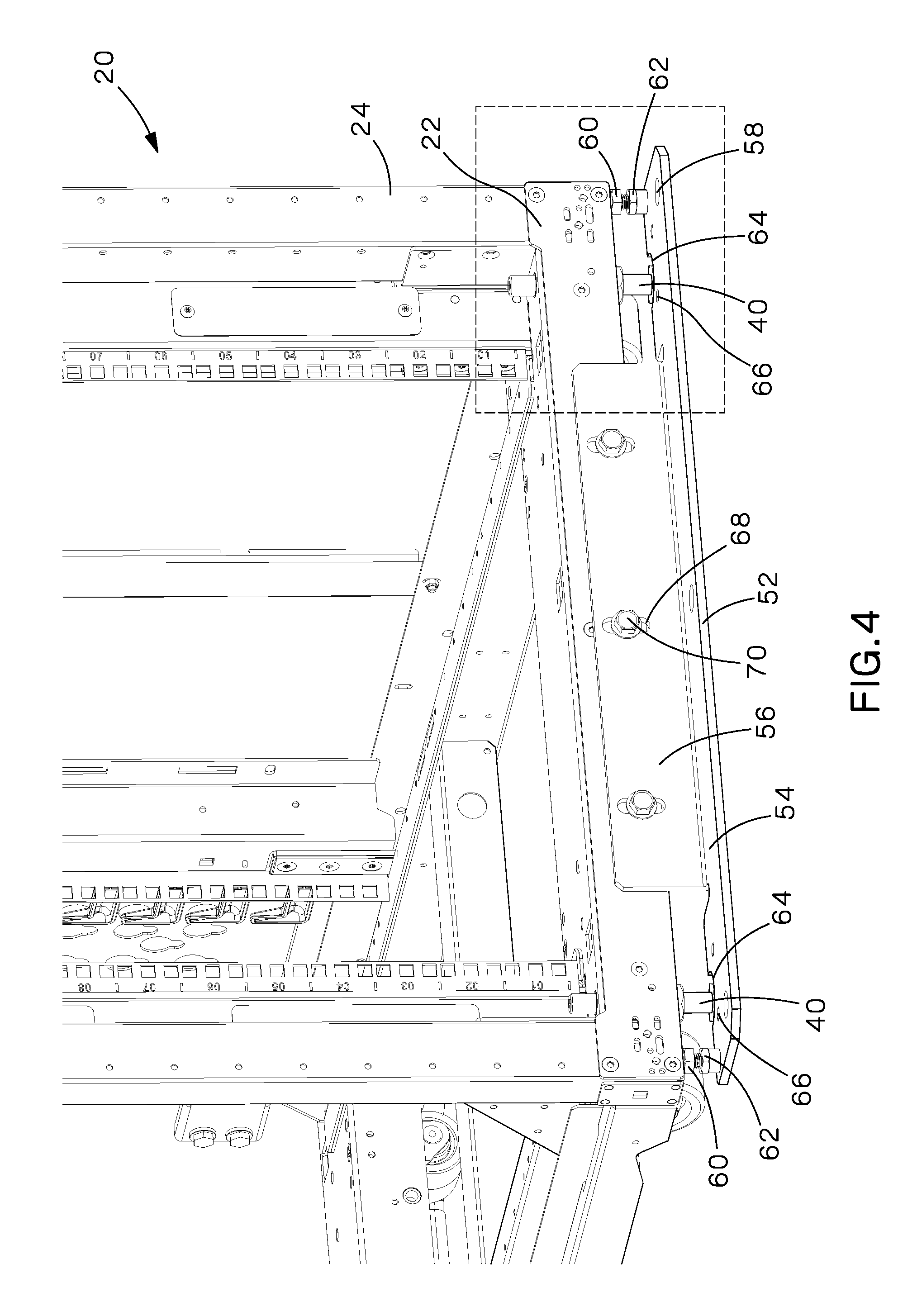
FIG. 4 is a front perspective view of the bracket of FIG. 3 installed on the front cabinet frame.
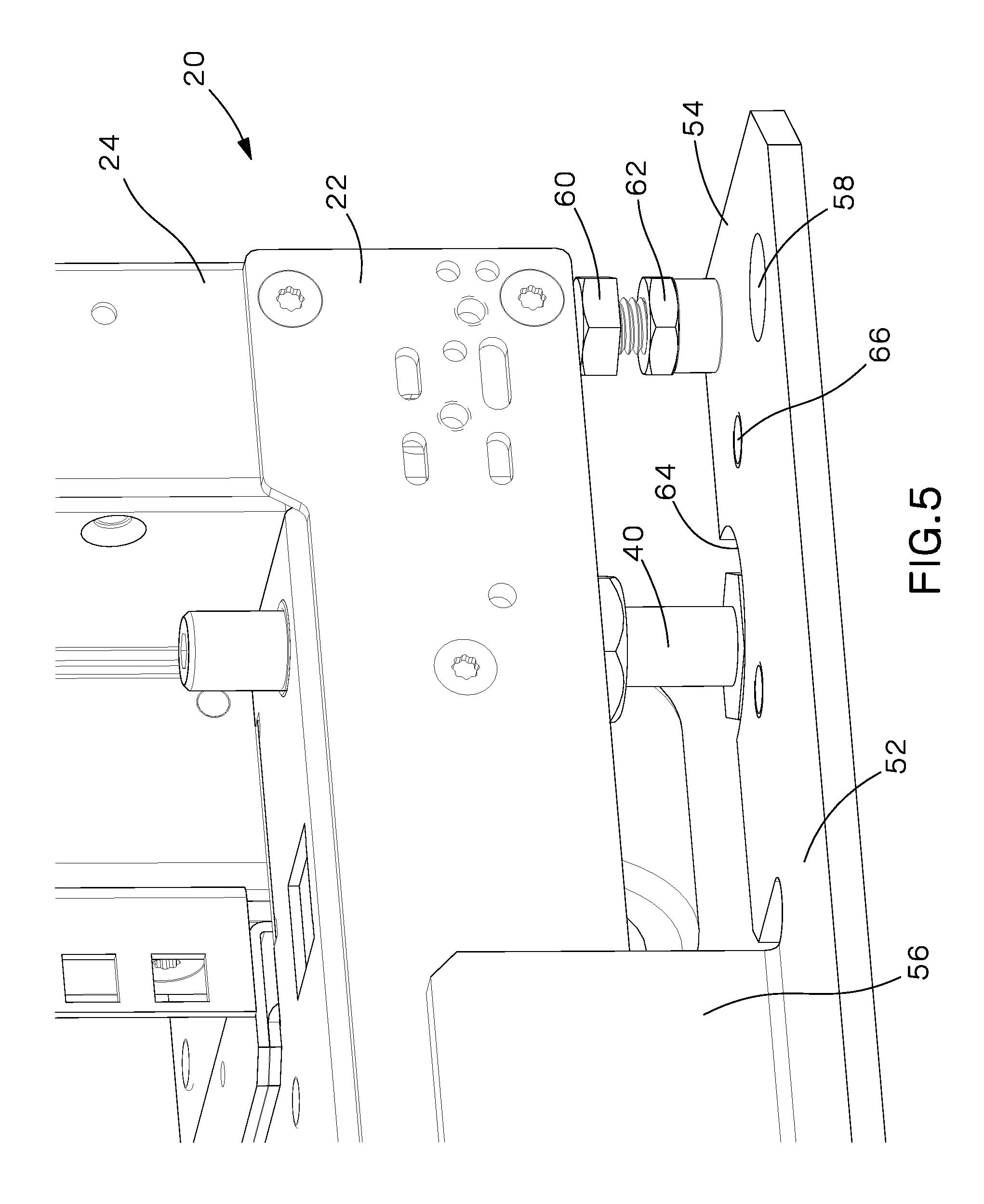
FIG. 5 is a front perspective view of one of the leveling feet of the seismic kit of FIG. 4.
FIG. 6 is a front exploded view of the leveling leg clamps of the seismic kit positioned to be installed on the seismic bracket of FIG. 4.
FIG. 7 is a rear perspective view of the complete seismic kit of FIG. 6 installed on the front of the cabinet.
DETAILED DESCRIPTION
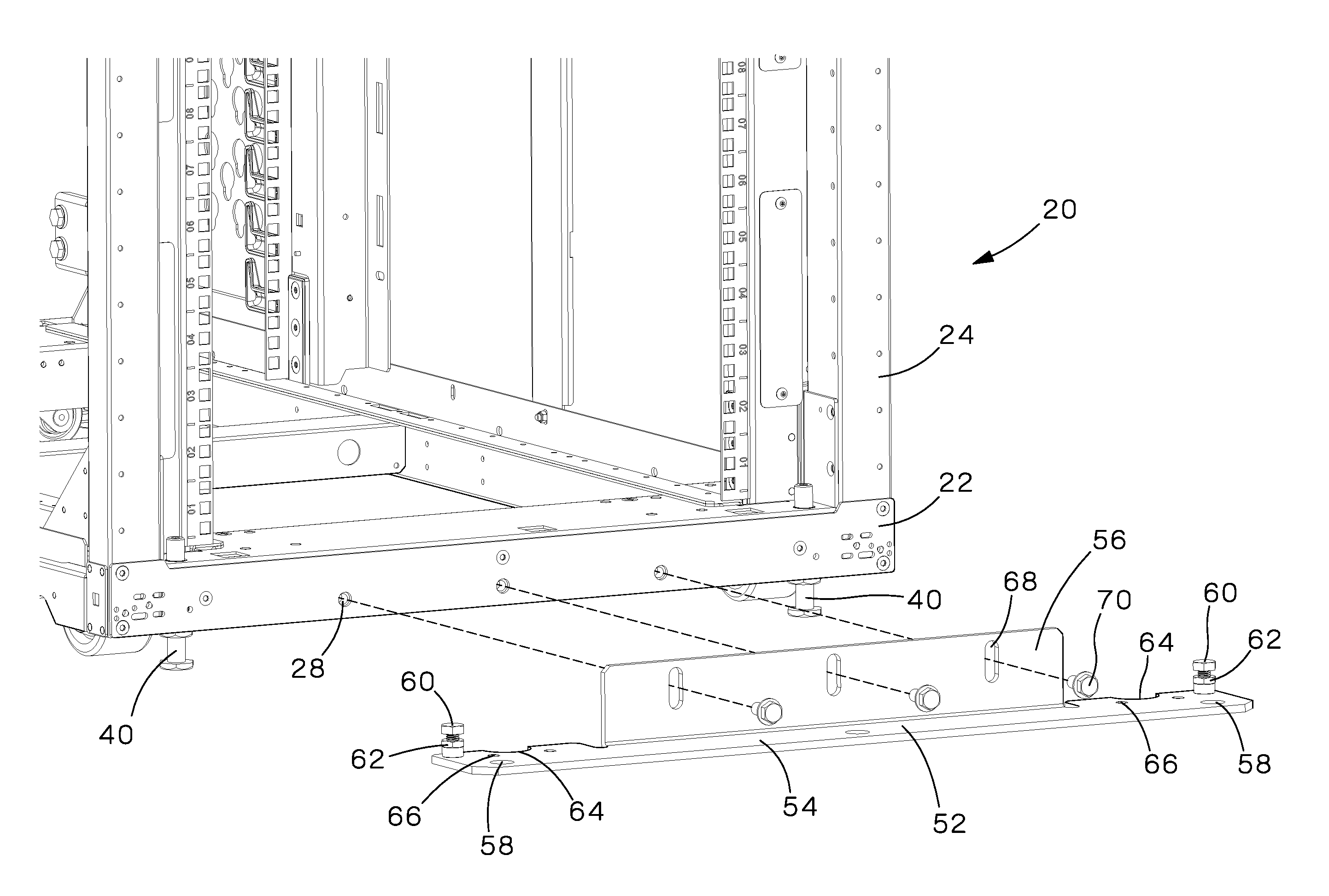
The seismic kit 50 of the present invention is installed on cabinets 20 in data centers located in seismic zones. The seismic kit 50 is bolted on the front and back of the cabinet frame which allows for simplicity during the cabinet placement process. The seismic kit 50 also assures a cabinet height flexibility which enables alignment during ganging of multiple cabinets. As described below, once a cabinet is placed in a desired location, the seismic kit 50 is installed on the cabinet and then secured to floor. The seismic kit 50 includes additional bracing to secure the cabinet 20 to eliminate excessive cabinet deflection during a seismic event.
FIG. 1 illustrates a dynamic cabinet 20 with the seismic kit 50 of the present invention secured on the front 24 of the cabinet 20 and the back 26 of the cabinet 20. FIG. 2 illustrates the seismic bracket 52 and leveling leg clamps 72 of the seismic kit 50 secured to the front 24 of the cabinet 20.
FIGS. 3-7 illustrate the assembly of the seismic kit 50. FIG. 3 illustrates a front 24 of the cabinet 20 with the door removed. The cabinet 20 includes a frame 22 with a plurality of threaded holes 28 along the bottom of the cabinet frame 22. The cabinet 20 also includes a leveling leg 40 located at each corner of the cabinet 20. Once the cabinet 20 has been placed in the desired location, the leveling legs 40 of the cabinet 20 are lowered to the floor to stabilize the cabinet 20 from moving. The leveling legs 40 also help to adjust the height of the cabinets 20 to that of adjacent cabinets, if necessary.
As illustrated in FIG. 3, the seismic bracket 52 includes a first member 54 and a second member 56. The first member 54 extends the width of the cabinet frame 22. The first member 54 includes a plurality of openings or holes 58 for receiving fasteners (not illustrated) to secure the first member 54 to the floor.
Each end of the first member 54 includes an exterior leveling foot 60. When the seismic bracket 52 is installed on the cabinet 20, each leveling foot 60 is positioned between the first member 54 and the bottom of the cabinet 20. Each leveling foot 60 is secured via jam nuts 62. The first member 54 also includes semi-circular cutouts 64 with holes 66 surrounding each semi-circular cutout 64. As illustrated and described with respect to FIGS. 5 and 7, each semi-circular cutout 64 receives one of the leveling legs 40 extending from the cabinet 20.
The second member 56 extends upwards from the first member 54 at the center of the first member 54. The second member 56 is perpendicular to the first member 54. The second member 56 includes a plurality of elongated slots 68 for receiving a mounting bolt 70 to secure the seismic bracket 52 to the cabinet frame 22.
As illustrated in FIG. 4, the seismic bracket 52 is positioned adjacent to the front 24 of the cabinet frame 22. The semi-circular cutouts 64 of the first member 54 of the seismic bracket 52 surround the leveling legs 40 extending from the cabinet 20. The elongated slots 68 in the second member 56 of the seismic bracket 52 are aligned with the threaded holes 28 in the cabinet frame 22. Mounting bolts 70 secure the seismic bracket 52 to the cabinet frame 22. An identical seismic bracket 52 is also secured to the cabinet frame 22 at the back 26 of the cabinet 20.
After the seismic brackets 52 are secured, the exterior leveling feet 60 are raised to contact the outermost edges of the cabinet frame 22 (see FIG. 5). The jam nuts 62 are tightened to hold the leveling feet 60 in place. The leveling feet 60 reduce the ability of the cabinet frame 22 to sway during excessive side to side forces of a seismic event.
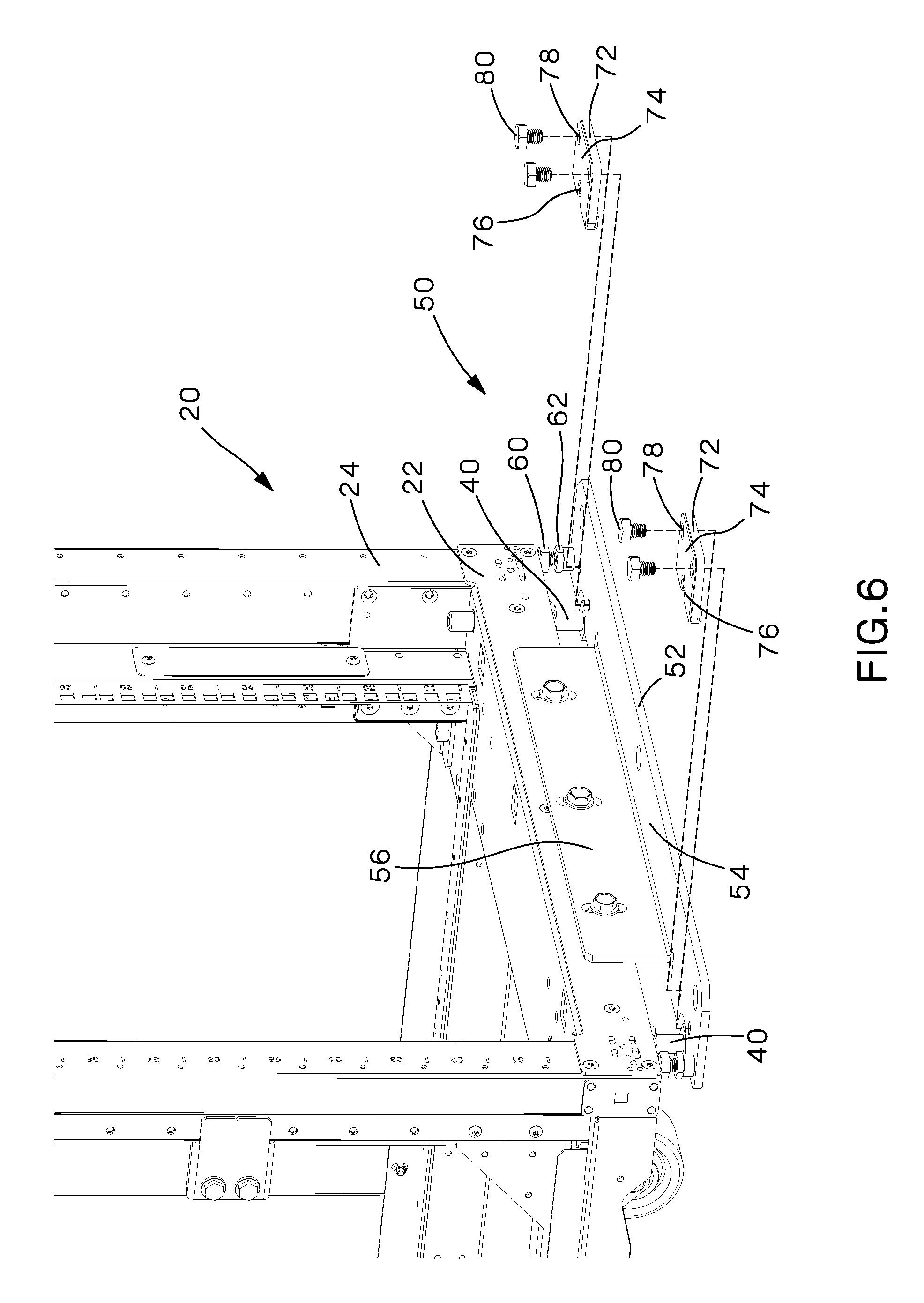
FIG. 6 illustrates an exploded view of the leveling leg clamps 72 prior to being secured to the seismic bracket 52. The leveling leg clamps 72 include a rectangular member 74 with a semi-circular cutout 76 and openings or holes 78 for receiving fasteners, such as leveling leg clamp bolts 80. The leveling leg clamps 72 are positioned on the first member 54 of the seismic bracket 52. The semi-circular cutouts 76 of the leveling leg clamps 72 align with the semi-circular cutouts 64 of the first member 54 of the seismic bracket 52. The leveling leg clamp bolts 80 secure the leveling leg clamps 72 to the first member 54.
As illustrated in FIG. 7, the aligned semi-circular cutouts 76, 64 of each leveling leg clamp 72 and the first member 54, respectively, receive one of the leveling legs 40 extending from the cabinet 20. Installing the leveling leg clamps 72 around the leveling legs 40 restrains the cabinet 20 from deflecting by reducing the vertical displacement of the leveling legs 40 due to side to side external forces.
Furthermore, while the preferred embodiments of the present invention have been shown and described, it will be obvious to those skilled in the art that changes and modifications may be made without departing from the teaching of the invention. The matter set forth in the foregoing description and accompanying drawings is offered by way of illustration only and not as limitation.
* * * * *
D00000
D00001
D00002
D00003
D00004
D00005
D00006
D00007
XML
uspto.report is an independent third-party trademark research tool that is not affiliated, endorsed, or sponsored by the United States Patent and Trademark Office (USPTO) or any other governmental organization. The information provided by uspto.report is based on publicly available data at the time of writing and is intended for informational purposes only.
While we strive to provide accurate and up-to-date information, we do not guarantee the accuracy, completeness, reliability, or suitability of the information displayed on this site. The use of this site is at your own risk. Any reliance you place on such information is therefore strictly at your own risk.
All official trademark data, including owner information, should be verified by visiting the official USPTO website at www.uspto.gov. This site is not intended to replace professional legal advice and should not be used as a substitute for consulting with a legal professional who is knowledgeable about trademark law.