System and method for systemic detection of display errors
Dunn , et al. July 16, 2
U.S. patent number 10,353,785 [Application Number 15/262,837] was granted by the patent office on 2019-07-16 for system and method for systemic detection of display errors. This patent grant is currently assigned to MANUFACTURING RESOURCES INTERNATIONAL, INC.. The grantee listed for this patent is Manufacturing Resources International, Inc.. Invention is credited to William Dunn, John Schuch, David Williams.


| United States Patent | 10,353,785 |
| Dunn , et al. | July 16, 2019 |
| **Please see images for: ( Certificate of Correction ) ** |
System and method for systemic detection of display errors
Abstract
A system and method for systemically addressing failures in electronic displays without user interaction comprises an electronic display connected to a timing and control board, connected to a system control board having a network interface component with a power button. A video player is connected to the system control board and has a video player power button. The system control board may simulate pushing the power button, the video power button, and/or disrupting the power supply to the video player if the video player is not communicating.
| Inventors: | Dunn; William (Alpharetta, GA), Williams; David (Canton, GA), Schuch; John (Buford, GA) | ||||||||||
|---|---|---|---|---|---|---|---|---|---|---|---|
| Applicant: |
|
||||||||||
| Assignee: | MANUFACTURING RESOURCES
INTERNATIONAL, INC. (Alpharetta, GA) |
||||||||||
| Family ID: | 58240396 | ||||||||||
| Appl. No.: | 15/262,837 | ||||||||||
| Filed: | September 12, 2016 |
Prior Publication Data
| Document Identifier | Publication Date | |
|---|---|---|
| US 20170075777 A1 | Mar 16, 2017 | |
Related U.S. Patent Documents
| Application Number | Filing Date | Patent Number | Issue Date | ||
|---|---|---|---|---|---|
| 62216470 | Sep 10, 2015 | ||||
| Current U.S. Class: | 1/1 |
| Current CPC Class: | G06F 11/0757 (20130101); G06F 11/2028 (20130101); G06F 11/2025 (20130101); G06F 11/203 (20130101); G06F 11/3041 (20130101); G06F 11/3476 (20130101); G06F 2201/805 (20130101) |
| Current International Class: | G06F 11/20 (20060101); G06F 11/30 (20060101); G06F 11/07 (20060101); G06F 11/34 (20060101) |
References Cited [Referenced By]
U.S. Patent Documents
| 5162785 | November 1992 | Fagard |
| 5351201 | September 1994 | Harshbarger, Jr. et al. |
| 5590831 | January 1997 | Manson et al. |
| 5751346 | May 1998 | Dozier et al. |
| 5786801 | July 1998 | Ichise |
| 5952992 | September 1999 | Helms |
| 6144359 | November 2000 | Grave |
| 6157143 | December 2000 | Bigio et al. |
| 6215411 | April 2001 | Gothard |
| 6222841 | April 2001 | Taniguchi |
| 6259492 | July 2001 | Imoto et al. |
| 6384736 | May 2002 | Gothard |
| 6421694 | July 2002 | Nawaz et al. |
| 6509911 | January 2003 | Shimotono |
| 6546294 | April 2003 | Kelsey et al. |
| 6553336 | April 2003 | Johnson et al. |
| 6587525 | July 2003 | Jeong et al. |
| 6753842 | June 2004 | Williams et al. |
| 6812851 | November 2004 | Dukach et al. |
| 6850209 | February 2005 | Mankins et al. |
| 6968375 | November 2005 | Brown |
| 7038186 | May 2006 | De Brabander et al. |
| 7064672 | June 2006 | Gothard |
| 7319862 | January 2008 | Lincoln et al. |
| 7330002 | February 2008 | Joung |
| 7369058 | May 2008 | Gothard |
| 7380265 | May 2008 | Jensen et al. |
| 7391317 | June 2008 | Abraham et al. |
| 7451332 | November 2008 | Culbert et al. |
| 7474294 | January 2009 | Leo et al. |
| 7577458 | August 2009 | Lin |
| 7581094 | August 2009 | Apostolopoulos et al. |
| 7595785 | September 2009 | Jang |
| 7612278 | November 2009 | Sitrick et al. |
| 7614065 | November 2009 | Weissmueller, Jr. et al. |
| 7636927 | December 2009 | Zigmond et al. |
| 7675862 | March 2010 | Pham et al. |
| 7751813 | July 2010 | Varanda |
| 7764280 | July 2010 | Shiina |
| 7774633 | August 2010 | Harrenstien et al. |
| 7795821 | September 2010 | Jun |
| 7949893 | May 2011 | Knaus |
| 8212921 | July 2012 | Yun |
| 8218812 | July 2012 | Sugimoto et al. |
| 8248203 | August 2012 | Hanwright et al. |
| 8441574 | May 2013 | Dunn et al. |
| 8601252 | December 2013 | Mendelow |
| 8689343 | April 2014 | De Laet |
| 8983385 | March 2015 | Macholz |
| 9026686 | May 2015 | Dunn et al. |
| 2002/0019933 | February 2002 | Friedman et al. |
| 2002/0026354 | February 2002 | Shoji et al. |
| 2002/0112026 | August 2002 | Fridman et al. |
| 2002/0120721 | August 2002 | Eilers et al. |
| 2002/0147648 | October 2002 | Fadden et al. |
| 2002/0152425 | October 2002 | Chaiken et al. |
| 2002/0163513 | November 2002 | Tsuji |
| 2002/0163916 | November 2002 | Oskouy et al. |
| 2002/0164962 | November 2002 | Mankins et al. |
| 2002/0190972 | December 2002 | Ven de Van |
| 2002/0194365 | December 2002 | Jammes |
| 2002/0194609 | December 2002 | Tran |
| 2003/0031128 | February 2003 | Kim et al. |
| 2003/0039312 | February 2003 | Horowitz et al. |
| 2003/0061316 | March 2003 | Blair et al. |
| 2003/0097497 | May 2003 | Esakov |
| 2003/0098881 | May 2003 | Nolte et al. |
| 2003/0161354 | August 2003 | Bader et al. |
| 2003/0177269 | September 2003 | Robinson et al. |
| 2003/0196208 | October 2003 | Jacobson |
| 2003/0214242 | November 2003 | Berg-johansen |
| 2003/0230991 | December 2003 | Muthu et al. |
| 2004/0036697 | February 2004 | Kim et al. |
| 2004/0138840 | July 2004 | Wolfe |
| 2004/0158872 | August 2004 | Kobayashi |
| 2004/0194131 | September 2004 | Ellis et al. |
| 2004/0243940 | December 2004 | Lee et al. |
| 2004/0252400 | December 2004 | Blank et al. |
| 2004/0253947 | December 2004 | Phillips et al. |
| 2005/0033840 | February 2005 | Nisani et al. |
| 2005/0070335 | March 2005 | Jitsuishi et al. |
| 2005/0071252 | March 2005 | Henning et al. |
| 2005/0073518 | April 2005 | Bontempi |
| 2005/0088984 | April 2005 | Chin et al. |
| 2005/0123001 | June 2005 | Craven et al. |
| 2005/0132036 | June 2005 | Jang et al. |
| 2005/0179554 | August 2005 | Lu |
| 2005/0184983 | August 2005 | Brabander et al. |
| 2005/0216939 | September 2005 | Corbin |
| 2005/0231457 | October 2005 | Yamamoto et al. |
| 2005/0267943 | December 2005 | Castaldi et al. |
| 2005/0289061 | December 2005 | Kulakowski et al. |
| 2005/0289588 | December 2005 | Kinnear |
| 2006/0007107 | January 2006 | Ferguson |
| 2006/0022616 | February 2006 | Furukawa et al. |
| 2006/0150222 | July 2006 | McCafferty et al. |
| 2006/0160614 | July 2006 | Walker et al. |
| 2006/0269216 | November 2006 | Wiemeyer et al. |
| 2007/0039028 | February 2007 | Bar |
| 2007/0157260 | July 2007 | Walker |
| 2007/0168539 | July 2007 | Day |
| 2007/0200513 | August 2007 | Ha et al. |
| 2007/0214812 | September 2007 | Wagner et al. |
| 2007/0237636 | October 2007 | Hsu |
| 2007/0268241 | November 2007 | Nitta et al. |
| 2007/0273519 | November 2007 | Ichikawa et al. |
| 2007/0274400 | November 2007 | Murai et al. |
| 2007/0286107 | December 2007 | Singh et al. |
| 2007/0291198 | December 2007 | Shen |
| 2008/0008471 | January 2008 | Dress |
| 2008/0024268 | January 2008 | Wong et al. |
| 2008/0034205 | February 2008 | Alain et al. |
| 2008/0037466 | February 2008 | Ngo et al. |
| 2008/0037783 | February 2008 | Kim et al. |
| 2008/0055297 | March 2008 | Park |
| 2008/0096559 | April 2008 | Phillips et al. |
| 2008/0104631 | May 2008 | Krock et al. |
| 2008/0111958 | May 2008 | Kleverman et al. |
| 2008/0112601 | May 2008 | Warp |
| 2008/0136770 | June 2008 | Peker et al. |
| 2008/0163291 | July 2008 | Fishman et al. |
| 2008/0185976 | August 2008 | Dickey et al. |
| 2008/0218501 | September 2008 | Diamond |
| 2008/0246871 | October 2008 | Kupper et al. |
| 2008/0266554 | October 2008 | Sekine et al. |
| 2008/0267328 | October 2008 | Ianni et al. |
| 2008/0278099 | November 2008 | Bergfors et al. |
| 2008/0281165 | November 2008 | Rai et al. |
| 2008/0303918 | December 2008 | Keithley |
| 2008/0313691 | December 2008 | Cholas et al. |
| 2009/0009997 | January 2009 | Sanfilippo et al. |
| 2009/0015400 | January 2009 | Breed |
| 2009/0036190 | February 2009 | Brosnan et al. |
| 2009/0079416 | March 2009 | Vinden et al. |
| 2009/0104989 | April 2009 | Williams et al. |
| 2009/0152445 | June 2009 | Gardner, Jr. |
| 2009/0164615 | June 2009 | Akkanen |
| 2009/0273568 | November 2009 | Milner |
| 2009/0315867 | December 2009 | Sakamoto et al. |
| 2010/0017526 | January 2010 | Jagannath et al. |
| 2010/0037274 | February 2010 | Meuninck et al. |
| 2010/0060550 | March 2010 | McGinn et al. |
| 2010/0083305 | April 2010 | Acharya et al. |
| 2010/0177157 | July 2010 | Stephens et al. |
| 2010/0177158 | July 2010 | Walter |
| 2010/0177750 | July 2010 | Essinger et al. |
| 2010/0198983 | August 2010 | Monroe et al. |
| 2010/0231563 | September 2010 | Dunn et al. |
| 2010/0237697 | September 2010 | Dunn et al. |
| 2010/0238299 | September 2010 | Dunn et al. |
| 2010/0299556 | November 2010 | Taylor et al. |
| 2011/0019636 | January 2011 | Fukuoka et al. |
| 2011/0047567 | February 2011 | Zigmond et al. |
| 2011/0078536 | March 2011 | Han et al. |
| 2011/0283199 | November 2011 | Schuch et al. |
| 2012/0105424 | May 2012 | Lee et al. |
| 2012/0203872 | August 2012 | Luby et al. |
| 2012/0302343 | November 2012 | Hurst et al. |
| 2012/0308191 | December 2012 | Chung |
| 2013/0162908 | June 2013 | Son et al. |
| 2014/0002747 | January 2014 | Macholz |
| 2015/0250021 | September 2015 | Stice et al. |
| 2016/0034240 | February 2016 | Kreiner et al. |
| 2017/0075777 | March 2017 | Dunn et al. |
| 2017/0315886 | November 2017 | Helmick |
| 0313331 | Feb 1994 | EP | |||
| 1821538 | Aug 2007 | EP | |||
| 2351369 | Aug 2011 | EP | |||
| 2396964 | Dec 2011 | EP | |||
| 61-234690 | Oct 1986 | JP | |||
| 61-251901 | Nov 1986 | JP | |||
| 7-74224 | Mar 1995 | JP | |||
| 2000122575 | Apr 2000 | JP | |||
| 2002064842 | Feb 2002 | JP | |||
| 2002209230 | Jul 2002 | JP | |||
| 2005-211449 | Aug 2005 | JP | |||
| 2005-211451 | Aug 2005 | JP | |||
| 2005236469 | Sep 2005 | JP | |||
| 2005333568 | Dec 2005 | JP | |||
| WO9608892 | Mar 1996 | WO | |||
| WO2008050402 | May 2008 | WO | |||
| WO2011106683 | Sep 2011 | WO | |||
| WO2017044952 | Mar 2017 | WO | |||
Other References
|
Photo Research, PR-650 SpectraScan Colorimeter, 1999, 2 Pages. cited by applicant . Texas Advanced Optoelectronic Solutions, TCS230 Programmable Color Light-To-Frequency Converter, 2007, 12 Pages. cited by applicant . Don Methven, Wireless Video Streaming: An Overview, Nov. 16, 2002, 7 Pages. cited by applicant . Outdoorlink, Inc., SmartLink Website User Manual, http://smartlink.outdoorlinkinc.com/docs/SmartLinkWebsiteUserManual.pdf, 2017, 33 pages. cited by applicant . Outdoorlink, Inc., SmartLink One, One Relay, http://smartlinkcontrol.com/billboard/one-relay/, retrieved Apr. 17, 2019, 2007-16, 6 pages. cited by applicant . Outdoorlink, Inc., SmartLink One Out of Home Media Controller, 2016, 1 page. cited by applicant. |
Primary Examiner: Riad; Amine
Attorney, Agent or Firm: Standley Law Group LLP Standley; Jeffrey S. Smith; Adam J.
Parent Case Text
CROSS-REFERENCE TO RELATED APPLICATIONS
This application claims the benefit of U.S. Provisional Application No. 62/216,470, filed Sep. 10, 2015, the disclosure of which is incorporated herein by reference.
Claims
We claim:
1. A system for systemically addressing failures in electronic displays without user interaction comprising: a plurality of electronic display assembles, each comprising: an electronic display; a system control board electrically connected to the electronic display and comprising a network interface component; and at least one video player electrically connected to the system control board; and a network operations center in electronic communication with the network interface component of each respective electronic display assembly, wherein the network operations center is located remote from the plurality of electronic display assemblies; wherein each of the system control boards are configured to simulate a short push of the power button by sending the respective video player instructions to restart if the video player is not communicating, and simulate a long push of the power button by sending the respective video player force restart instructions if the video player is not communicating after simulating a short push of the power button; wherein each of the network interface components are electrically connected to the power supply for the respective video player by way of the respective system control board such that each of the system control boards are configured to remove power supplied to the respective video player, wait a predetermined amount of time, and resume applying power to the respective video player if the video player is not communicating after simulating a long push of the power button for the respective video player.
2. The system of claim 1 wherein: each of the network interface components are configured to receive instructions from the network operations center and transmit operation information to the network operations center, wherein the operation information indicates whether the video player is communicating.
3. The system of claim 1 wherein: the system control board is configured to store a downtime event if the video player is not communicating.
4. The system of claim 3 wherein: the system control board is configured to transmit the downtime event to the network operations center.
5. The system of claim 1 wherein: each of the electronic display assemblies comprises a first and a second video player; the system control board for each electronic display assembly is configured to designate one of the first and second video players as primary and the other video player as secondary; the system control board for each electronic display assembly is configured to drive the electronic display using the primary video player; and the system control board for each electronic display assembly is configured to switch to the secondary video player if the primary video player is not communicating.
6. The system of claim 5 wherein: the system control board for each electronic display assembly is configured to switch to the secondary video player for the respective display assembly only if the primary video player for the respective display assembly is not communicating after removing power supplied to the primary video player, waiting a predetermined amount of time, and resuming the application of power to the primary video player.
7. The system of claim 6 wherein: the system is configured to switch back to the primary video player if the secondary video player is not communicating and the primary video player is communicating.
8. A method for systemically addressing failures in electronic displays without user interaction comprising the steps of: providing a number of display assemblies, each comprising an electronic display, a system control board, and a video player, wherein each of the display assemblies are in electronic communication with a remote network operations center; applying power to each of the display assemblies; allowing time for each of the display assemblies to boot up; monitoring each of the video players to determine whether the respective video player is communicating; notifying the network operations center of a downtime event upon determination that one of the video players is not communicating; instructing the non-communicating video player to simulate a short push of the power button by sending the respective video player instructions to restart upon determination that the video player is not communicating; upon determination that the non-communicating video player remains non-communicative after simulating a short push of the power button, instructing the non-communicating video player to simulate a long push of the video button by sending the non-communicating video player instructions force restart instructions; and upon determination that the non-communicating video player remains non-communicative after simulating a long push of the power button: ceasing to apply power to the non-communicating video player; waiting a predetermined amount of time; and reapplying power to the non-communicating video player.
9. The method of claim 8 wherein: the step of notifying the network operations center of a downtime event comprises the sub-steps of: recording a downtime event at the system control board; and transmitting the downtime event to the network operations center.
10. The method of claim 8 wherein: each of the display assemblies further comprises a second video player.
11. The method of claim 9 further comprising the steps of: instructing the respective display assembly to operate the electronic display with the second video player upon determination that the video player is not communicating.
Description
TECHNICAL FIELD
Embodiments generally relate to electronic displays typically used for advertising, information, and point of sale applications.
BACKGROUND OF THE ART
Electronic displays are now being used in indoor, outdoor, and semi-outdoor environments for advertising, information, as well as point of sale applications. Generally speaking, once installed, it is desirable to ensure operation throughout the life of the device. Downtime can be costly in that advertising revenue and opportunities can be lost, information will not be effectively transmitted to the public, and customers cannot view the purchase options in a point of sale application.
SUMMARY OF THE EXEMPLARY EMBODIMENTS
The exemplary embodiments herein provide a system and method for monitoring one or more remote electronic displays for possible failures, and providing system logic so that failures can be addressed immediately by the system, without requiring any user intervention. The system can monitor a number of system attributes such as heartbeat signals, status messages, LED light signals, video/image frame data, and network communications, while making near instantaneous changes in operation of the device in order to reduce or eliminate downtime of the displays.
The foregoing and other features and advantages of the present invention will be apparent from the following more detailed description of the particular embodiments, as illustrated in the accompanying drawings.
BRIEF DESCRIPTION OF THE DRAWINGS
A better understanding of an exemplary embodiment will be obtained from a reading of the following detailed description and the accompanying drawings wherein identical reference characters refer to identical parts and in which:
FIG. 1 is a simplified bock diagram of an exemplary embodiment of the overall system architecture.
FIG. 1A is a simplified block diagram of another exemplary embodiment of the overall system architecture.
FIG. 2 is a logical flowchart for operating a first embodiment of the system.
FIG. 3 is a logical flowchart for operating a second embodiment of the system.
FIG. 4 is a logical flowchart for operating a third embodiment of the system.
FIG. 5 is a logical flowchart for operating a fourth embodiment of the system.
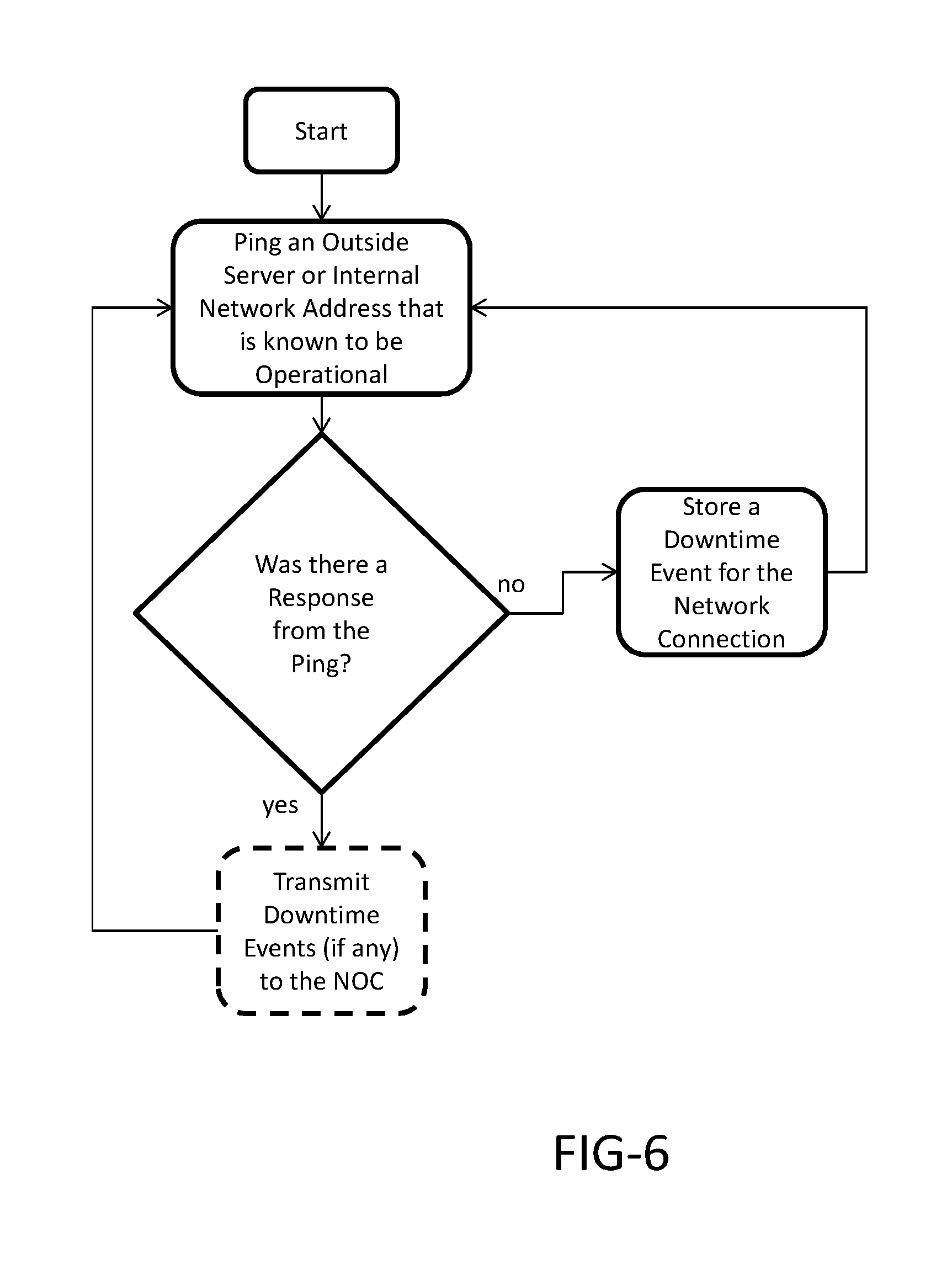
FIG. 6 is a logical flowchart for operating a fifth embodiment of the system.
FIG. 7 is a logical flowchart for operating a sixth embodiment of the system.
FIG. 8 is a logical flowchart for operating a seventh embodiment of the system.
FIG. 9 is a logical flowchart for operating an eighth embodiment of the system.
DETAILED DESCRIPTION
The invention is described more fully hereinafter with reference to the accompanying drawings, in which exemplary embodiments of the invention are shown. This invention may, however, be embodied in many different forms and should not be construed as limited to the exemplary embodiments set forth herein. Rather, these embodiments are provided so that this disclosure will be thorough and complete, and will fully convey the scope of the invention to those skilled in the art. In the drawings, the size and relative sizes of layers and regions may be exaggerated for clarity.
The terminology used herein is for the purpose of describing particular embodiments only and is not intended to be limiting of the invention. As used herein, the singular forms "a", "an" and "the" are intended to include the plural forms as well, unless the context clearly indicates otherwise. It will be further understood that the terms "comprises" and/or "comprising," when used in this specification, specify the presence of stated features, integers, steps, operations, elements, and/or components, but do not preclude the presence or addition of one or more other features, integers, steps, operations, elements, components, and/or groups thereof.
Embodiments of the invention are described herein with reference to illustrations that are schematic illustrations of idealized embodiments (and intermediate structures) of the invention. As such, variations from the shapes of the illustrations as a result, for example, of manufacturing techniques and/or tolerances, are to be expected. Thus, embodiments of the invention should not be construed as limited to the particular shapes of regions illustrated herein but are to include deviations in shapes that result, for example, from manufacturing.
Unless otherwise defined, all terms (including technical and scientific terms) used herein have the same meaning as commonly understood by one of ordinary skill in the art to which this invention belongs. It will be further understood that terms, such as those defined in commonly used dictionaries, should be interpreted as having a meaning that is consistent with their meaning in the context of the relevant art and will not be interpreted in an idealized or overly formal sense unless expressly so defined herein.
Initially it should be noted that one of ordinary skill in the art understands that electronic displays as described herein are capable of displaying both still images as well as videos. Thus, it should be recognized that the terms `image` and `video` may be used interchangeably herein. Further, one having an ordinary level of skill in the arts will also understand that the electrical connections described herein may be wired or wireless.
FIG. 1 is a simplified bock diagram of an exemplary embodiment of the overall system architecture. A system control board 101 preferably contains at least a processor 50, electronic storage 60, and a network interface component 70 (which preferably includes a power button 75). In exemplary embodiments of the present invention, the power button 75 is electrically connected to the system control board 101 such that the system control board 101 may simulate the user physically pressing the power button 75 as will be explained in greater detail herein. For example, but without limitation, the network interface component 70 may be electrically connected to the power button 75 via the power control header on the system control board 101. Similarly, the system control board 101 may be electrically connected to a power supply for the display assembly 200a such that the system control board 101 may simulate the user physically removing the power supply (i.e., unplugging) and reattaching the power supply (i.e., plugging back in).
A timing and control board (TCON) 102 is preferably in electrical connection with the system control board 101 as well as the electronic display 30. A primary video player 103a is also preferably in electrical connection with the system control board 101. An optional secondary video player 103b may also be in electrical connection with the system control board 101. Each video player preferably includes a power button 104 and a power LED 105 (labeled 104a, 105a, 104b, and 105b, respectively). Similar to the power button 75, the network interface component 70 may be electrically connected to the power button 104 and the power LED 105 as well as the power supply source to the video players 103a and 103b by way of the system control board 101 such that the system may simulate physically pressing the power button 104 as well as physically removing the power supply to the video players 103 and reattaching it.
A network operations center device 200 preferably contains at least a processor 51, electronic storage 61, and a network interface component 71 which communicates with the network interface component 70 on the display assembly 200a. Two other display assemblies 200b and 200c are shown in electrical connection with the network operations center device 200, and each would preferably have the same components as shown and described for the display assembly 200a, but this is not required. In some embodiments however, there could be even more than three display assemblies in electrical connection with the network operations center device.
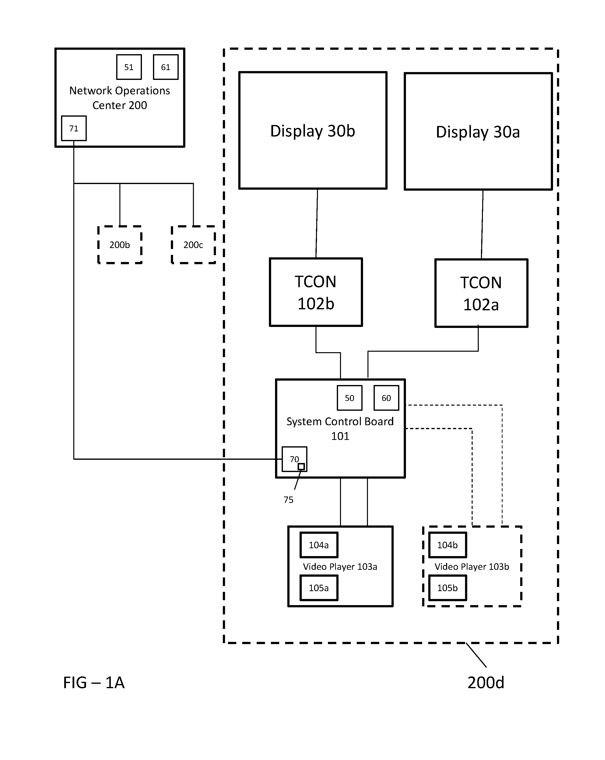
FIG. 1A is a simplified block diagram of another exemplary embodiment of the overall system architecture. In this embodiment the display assembly 200d may be similar to that show in FIG. 1, but be comprised of a first display 30a and a second display 30b. The first display 30a may be in electrical connection with a first TCON 102a and the second display 30b may be in electrical connection with a second TCON 102b. The first and second TCONs 102a and 102b, respectively, may be in electrical communication with the system control board 101. The video players 103a and 103b may each comprise two electrical connections with the system control board 101 such that each video player 103a and 103b may control both the first and the second displays 30a and 30b.
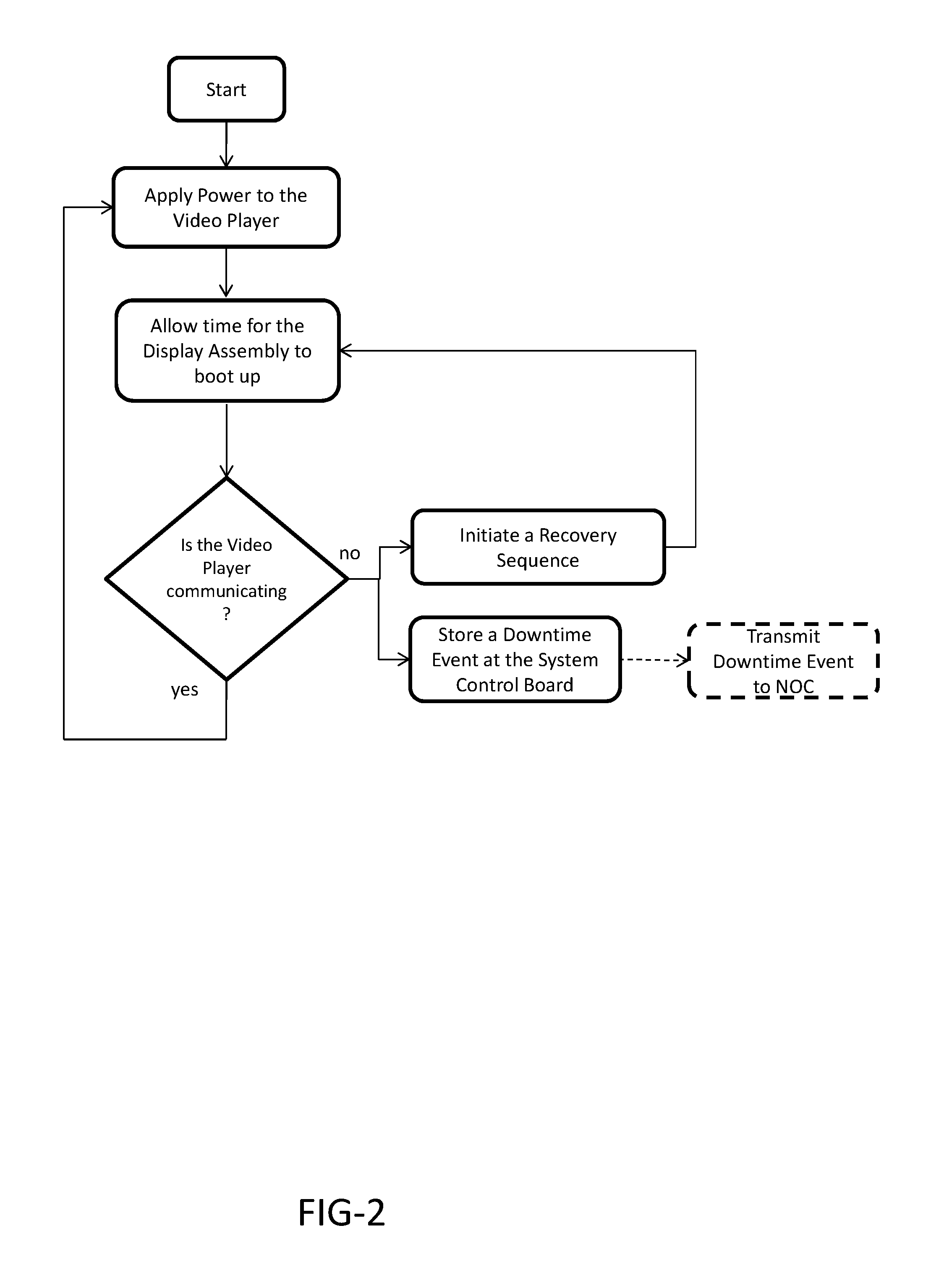
FIG. 2 is a logical flowchart for operating a first embodiment of the system. In this embodiment, the system begins by applying power to the video player 103a. The system may next allow time for the display assembly to boot up, such as but not limited to, by use of a timer or counter.
In this embodiment, the system may then monitor the video player 103a to see if it is communicating, thus indicating normal operation. The system may monitor the video player 103a by checking for a heartbeat signal, which is periodically generated by the video player 103a to indicate normal operation or to synchronize other parts of the system. Alternatively, the system may monitor the signal from the power LED 105 to see if it is active. As another alternative, the system may transmit a ping to see if the video player 103a responds. In still further alternate embodiments, the system may check for status messages that may be periodically sent from the player 103a to the control board 101. If the video player 103a is communicating though any of the aforementioned or other means, the system may continue to apply power to the video player 103a.
If the video player 103a is not communicating, the system may do one of two things. First, the system may initiate a recovery sequence as described in greater detail in FIG. 9. Second, the system may store a downtime event or failure data at the system control board 101 and optionally transmit the downtime event or failure data to the NOC device 200. In some embodiments, the system may perform both functions when no communication is detected from the player 103a.
Regardless, if the video player 103 is communicating, the system may return to the beginning of the logic and simply apply power to the video player 103a while continuing to monitor the signal from the power LED 105a.
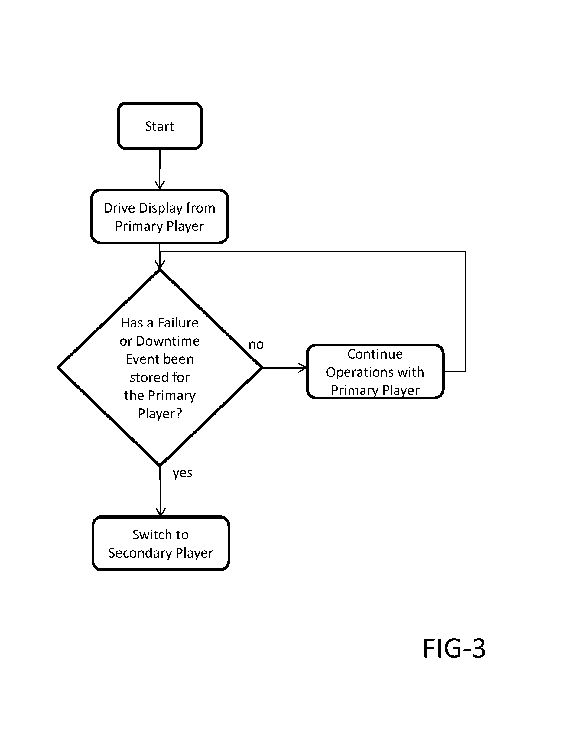
FIG. 3 is a logical flowchart for operating a second embodiment of the system. Here the system begins by driving the display 30 from the primary player 103a. The system would then check to determine if any failure data or downtime event had been stored for the primary player 103a and if not, the system continues the normal operations with the primary player 103a. If any failure data or downtime event had been stored for the primary player 103a, the system may then switch to drive the display 30 from the secondary player 103b. For example, but not to serve as a limitation, a failure or downtime event may include no video being shown on the display 30, an unsupported resolution format being received, an unsupported frame rate being received, an error message being received, or the like.
Those having an ordinary level of skill in the arts will recognize that any threshold of amount, frequency, or type of failure data or downtime events may be set such that the system will not switch between the primary player 103a and the secondary player 103b until the threshold has been met or exceeded.
FIG. 4 is a logical flowchart for operating a third embodiment of the system. In this embodiment, the system begins with logic similar to that shown and described above with respect to FIG. 3.
Under normal operating conditions, the system may drive the display 30 from the first video player 103a. However, once the system switches to the secondary player 103b, the system would preferably check to determine if the second video player 103b is communicating. If so, the system may continue normal operations with the second video player 103b. If not, the system may then do one of two things. First, the system may initiate a recovery sequence on the second video player 103b as previously discussed. Second, or in addition, the system may check to see if the first video player 103a is communicating. Preferably, the system first initiates the recovery sequence and only checks to see if the primary players is communicating after finding that the recovery sequence in unsuccessful. If the first video player 103a is communicating, the system may switch back to the first video player 103a. If not, the system may store a downtime event or failure data at the system control board 101 and optionally transmit the downtime event or failure data to the NOC device 200. In some embodiments, the system may perform both functions when the first video player 103a is not communicating. Further, if both the first and second video players 103a and 103b are not communicating, the system may direct the display assembly 200d to remain in a failure or downtime event condition. For example, but without limitation, the failure or downtime event condition may display a default or error message.
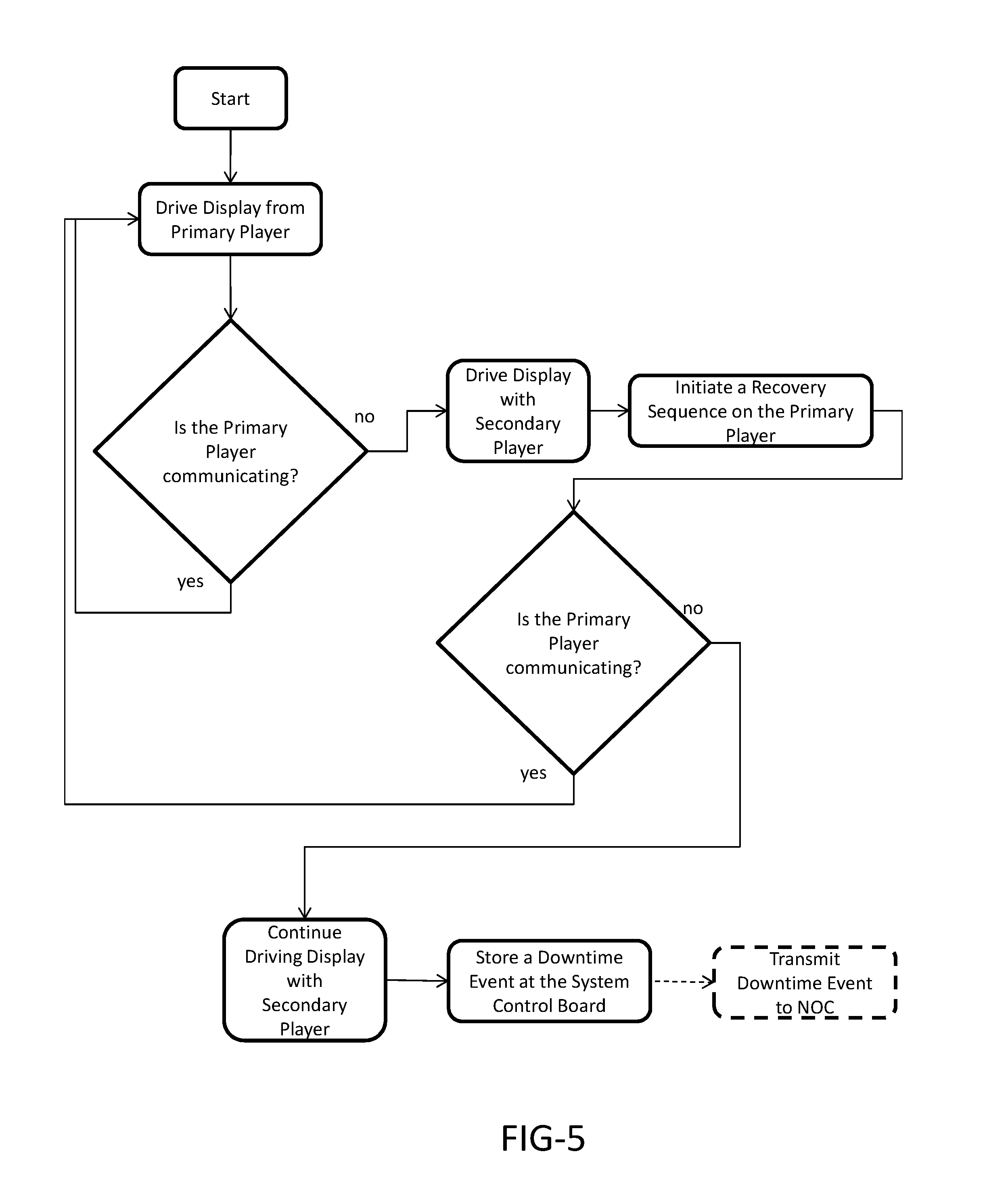
FIG. 5 is a logical flowchart for operating a fourth embodiment of the system. Here the system begins by driving the display 30 from the primary player 103a. The system would then check to determine if the primary player 103a is communicating. If so, the system continues normal operations with the primary player 103a. If not, the secondary player 103b would then be used to drive the display 30 and the system may force a power off of the primary player 103a and then initiate a recovery sequence on the primary player 103a. The system would then return to check if the primary player 103a is communicating. If so, the system resumes operations from the primary player 103a, using it to drive the display 30. If not, the system continues operations with the secondary player 103b and may store a downtime event or failure data at the system control board 101 and optionally may transmit the downtime event or failure data to the NOC device 200.
FIG. 6 is a logical flowchart for operating a fifth embodiment of the system. In this embodiment, the system begins by pinging an outside server or internal network address that is known (or assumed) to be operational. If there is no response from the ping, a downtime event is stored for the network connection, indicating some type of failure within the network and/or the network interface component 70. The system may then return to ping an outside server or internal network address that is known (or assumed) to be operational. If there is again no response, then a downtime event is again stored for the network connection. Once the system receives a response for the ping, it may optionally transmit one or all of the downtime events to the NOC device 200.
FIG. 7 is a logical flowchart for operating a sixth embodiment of the system. In this embodiment, the system begins by pinging an outside server or internal network address that is known (or assumed) to be operational. If there is a response to the ping, the system may return to re-ping an outside server or internal network address again in the future to confirm that the network is operating correctly. If there is no response from the ping, the system may initiate a recovery sequence of the network interface component 70. The system would preferably return again to re-ping an outside server or internal network address again in the future to confirm that the network is operating correctly.
FIG. 8 is a logical flowchart for operating a seventh embodiment of the system. In this embodiment, the system control board 101 may analyze each frame of video/image data from the video player 103a to determine if the frame data has changed over a period of time (T), which can be any period of time chosen by the user, where an exemplary period of time (T) may be on the order of 10-15 minutes, but again could be any period of time. If the frame data has changed, the system would return to have the control board 101 analyze more frames of video/image data. If the frame data has not changed over T, then a default image or video may be displayed while the system initiates a recovery sequence on the video player 103a. Optionally, the system may store a downtime event or failure data for the video player 103a at the system board 101. After running the recovery sequence on the video player 103a, the system may return to normal operations so that the control board 101 may analyze more frames of video/image data to confirm that either the video player 103a is now operating properly, continues to operate properly, or continues to have downtime or a failure.
FIG. 9 is a logical flowchart for operating an eighth embodiment of the system. Specifically, FIG. 9 describes an exemplary embodiment of the recovery sequence. The recovery sequence may include a simulation of the user depressing the power button 104a and/or attaching and reattaching the power supply (i.e., unplugging and re-plugging in the display assembly 200 or individual components thereof). The recovery sequence may comprise a simulated "short push" of the power button 104a, a "long push" of the power button 104a, and/or ceasing to supply power to the video player 103a and then reapplying power after a period of time has elapsed. The short push may simply command the video player 103a to restart. The long push may force the video player 103a to restart. Alternatively, or in addition, the recovery sequence may cut power to the video player 103 and then reapply power after a period of time has elapsed.
In exemplary embodiments of the present invention, the system may first simulate a short push of the power button 104a for the video player 103a and allow time for it to restart. The system may then check to see if the video player 103a is communicating. If so, the system may store a downtime event and optionally may transmit the downtime event to the network operations center 200. If not, the system may simulate a long push of the power button 104a and allow time for the video player 103a to reboot. The system may then check to see if the video player 103a is communicating. If so, the system may store a downtime event and optionally may transmit the downtime event to the network operations center 200. If not, the system may cease applying power to the video player 103a, wait a predetermined amount of time, and reapply power to the video player.
Optionally, the system may then check to see if the video player 103a is communicating. If so, the system may store a downtime event and optionally may transmit the downtime event to the network operations center 200. If not, the system may store a failure, optionally place the display assembly 200d in a default or failure mode, and optionally may transmit the failure to the network operations center 200.
While the recovery sequence is discussed with respect to the video player 103a and the respective power button 104a, it may be utilized with the second video player 103b and the respective power button 104b, the power button 75, as well as with other components of the system.
As used herein, a downtime event and/or failure is a data package representing any number of pieces of data including but not limited to the date and time for when the particular portion of the system went down, specifically which component of the system went down, how long the component was down, and the date and time for when operations resumed.
In exemplary embodiments of the present invention, and as discussed herein, the first video player 103a may be designated as the primary player, and the second video player 103b may be designated as the secondary player, though the reverse is contemplated.
The electronic display 30 can be any flat panel electronic display including but not limited to: liquid crystal displays (LCD), organic light emitting diode (OLED) displays, plasma displays, electroluminescent polymer displays, and the like.
Those having an ordinary level of skill in the arts will recognize that the buttons described herein, such as but not limited to the power button 75 and the power button 104, may be physical buttons or may be non-physical buttons such as an electrical signal, switch, circuit, transistor, or the like.
Having shown and described a preferred embodiment of the invention, those skilled in the art will realize that many variations and modifications may be made to affect the described invention and still be within the scope of the claimed invention. Additionally, many of the elements indicated above may be altered or replaced by different elements which will provide the same result and fall within the spirit of the claimed invention. It is the intention, therefore, to limit the invention only as indicated by the scope of the claims.
* * * * *
References
D00000
D00001
D00002
D00003
D00004
D00005
D00006
D00007
D00008
D00009
D00010
XML
uspto.report is an independent third-party trademark research tool that is not affiliated, endorsed, or sponsored by the United States Patent and Trademark Office (USPTO) or any other governmental organization. The information provided by uspto.report is based on publicly available data at the time of writing and is intended for informational purposes only.
While we strive to provide accurate and up-to-date information, we do not guarantee the accuracy, completeness, reliability, or suitability of the information displayed on this site. The use of this site is at your own risk. Any reliance you place on such information is therefore strictly at your own risk.
All official trademark data, including owner information, should be verified by visiting the official USPTO website at www.uspto.gov. This site is not intended to replace professional legal advice and should not be used as a substitute for consulting with a legal professional who is knowledgeable about trademark law.