Acetabular cup impacting using patient-specific instrumentation
Jansen , et al. July 16, 2
U.S. patent number 10,350,022 [Application Number 14/700,882] was granted by the patent office on 2019-07-16 for acetabular cup impacting using patient-specific instrumentation. This patent grant is currently assigned to ZIMMER, INC.. The grantee listed for this patent is ZIMMER, INC.. Invention is credited to Karine Duval, Bruno Falardeau, Herbert Andre Jansen, Di Li, Francois Paradis, Benoit Pelletier.


| United States Patent | 10,350,022 |
| Jansen , et al. | July 16, 2019 |
Acetabular cup impacting using patient-specific instrumentation
Abstract
A cup impactor assembly comprises a shaft. A cup coupler is at a cup end of the shaft and is releasably connecting a cup in fixed relation. A handle is at an impacting end of the shaft. A visual guide is mounted to at least one of the shaft and the handle, the visual guide producing visual guidance for pointing at at least two landmarks of the pelvis or fixed relative to the pelvis, based on a pre-planned patient-specific relation between the at least two landmarks and a desired acetabular cup orientation relative to the landmarks. A method for orienting an acetabular cup prior to impacting in an acetabulum of a pelvis is also provided.
| Inventors: | Jansen; Herbert Andre (Montreal, CA), Li; Di (LaSalle, CA), Duval; Karine (Montreal, CA), Falardeau; Bruno (Montreal, CA), Paradis; Francois (Boucherville, CA), Pelletier; Benoit (Montreal, CA) | ||||||||||
|---|---|---|---|---|---|---|---|---|---|---|---|
| Applicant: |
|
||||||||||
| Assignee: | ZIMMER, INC. (Warsaw,
IN) |
||||||||||
| Family ID: | 54354350 | ||||||||||
| Appl. No.: | 14/700,882 | ||||||||||
| Filed: | April 30, 2015 |
Prior Publication Data
| Document Identifier | Publication Date | |
|---|---|---|
| US 20150313723 A1 | Nov 5, 2015 | |
Related U.S. Patent Documents
| Application Number | Filing Date | Patent Number | Issue Date | ||
|---|---|---|---|---|---|
| 61986515 | Apr 30, 2014 | ||||
| Current U.S. Class: | 1/1 |
| Current CPC Class: | A61B 90/11 (20160201); A61B 90/30 (20160201); A61F 2/4609 (20130101); A61B 90/13 (20160201); A61F 2002/4687 (20130101); A61F 2002/4696 (20130101); A61F 2002/4629 (20130101); A61F 2/30942 (20130101); A61B 2090/395 (20160201); A61F 2002/4681 (20130101) |
| Current International Class: | A61F 2/46 (20060101); A61B 90/11 (20160101); A61B 90/13 (20160101); A61B 90/30 (20160101); A61B 90/00 (20160101); A61F 2/30 (20060101) |
| Field of Search: | ;606/91,87,99,102 |
References Cited [Referenced By]
U.S. Patent Documents
| 4841975 | June 1989 | Woolson |
| 5098383 | March 1992 | Hemmy et al. |
| 5490854 | February 1996 | Fisher et al. |
| 5768134 | June 1998 | Swaelens et al. |
| 5871018 | February 1999 | Delp et al. |
| 5916219 | June 1999 | Matsuno et al. |
| 7357057 | April 2008 | Chiang |
| 7468075 | December 2008 | Lang et al. |
| 7510557 | March 2009 | Bonutti |
| 7534263 | May 2009 | Burdulis |
| 7618451 | November 2009 | Berez et al. |
| 7634119 | December 2009 | Tsougarakis et al. |
| 7717956 | May 2010 | Lang |
| 7796791 | September 2010 | Tsougarakis et al. |
| 7799077 | September 2010 | Lang et al. |
| 7806896 | October 2010 | Bonutti |
| 7806897 | October 2010 | Bonutti |
| 7967868 | June 2011 | White et al. |
| 7981158 | July 2011 | Fitz et al. |
| 8062302 | November 2011 | Lang et al. |
| 8066708 | November 2011 | Lang et al. |
| 8070752 | December 2011 | Metzger et al. |
| 8077950 | December 2011 | Tsougarakis et al. |
| 8083745 | December 2011 | Lang et al. |
| 8092465 | January 2012 | Metzger et al. |
| 8094900 | January 2012 | Steines et al. |
| 8105330 | January 2012 | Fitz et al. |
| 8122582 | February 2012 | Burdulis, Jr. et al. |
| 8133234 | March 2012 | Meridew et al. |
| 8160345 | April 2012 | Pavlovskaia et al. |
| 8175683 | May 2012 | Roose |
| 8221430 | July 2012 | Park et al. |
| 8234097 | July 2012 | Steines et al. |
| 8241293 | August 2012 | Stone et al. |
| 8282646 | October 2012 | Schoenefeld et al. |
| 8298237 | October 2012 | Schoenefeld |
| 8337501 | December 2012 | Fitz et al. |
| 8337507 | December 2012 | Lang et al. |
| 8343218 | January 2013 | Lang et al. |
| 8366771 | February 2013 | Burdulis et al. |
| 8377129 | February 2013 | Fitz et al. |
| 8439926 | May 2013 | Bojarski et al. |
| 8460304 | June 2013 | Fitz et al. |
| 8480754 | July 2013 | Bojarski et al. |
| 8500740 | August 2013 | Bojarski et al. |
| 8529568 | September 2013 | Bouadi |
| 8529630 | September 2013 | Bojarski |
| 8585708 | September 2013 | Fitz et al. |
| 8545569 | October 2013 | Fitz et al. |
| 8551099 | October 2013 | Lang |
| 8551102 | October 2013 | Fitz et al. |
| 8551103 | October 2013 | Fitz et al. |
| 8551169 | October 2013 | Fitz et al. |
| 8556906 | October 2013 | Fitz et al. |
| 8556907 | October 2013 | Fitz et al. |
| 8556971 | October 2013 | Lang |
| 8556983 | October 2013 | Bojarski et al. |
| 8561278 | October 2013 | Fitz et al. |
| 8562611 | October 2013 | Fitz et al. |
| 8562618 | October 2013 | Fitz et al. |
| 8568479 | October 2013 | Fitz et al. |
| 8568480 | October 2013 | Fitz et al. |
| 8617172 | December 2013 | Fitz et al. |
| 8617242 | December 2013 | Philipp |
| 8623026 | January 2014 | Wong et al. |
| 8634617 | January 2014 | Tsougarakis et al. |
| 8638998 | January 2014 | Steines et al. |
| 8641716 | February 2014 | Fitz et al. |
| 8657827 | February 2014 | Fitz et al. |
| 8682052 | March 2014 | Fitz et al. |
| 2003/0055502 | March 2003 | Lang et al. |
| 2003/0216669 | November 2003 | Lang et al. |
| 2004/0073225 | April 2004 | Subba Rao |
| 2004/0133276 | July 2004 | Lang et al. |
| 2004/0138754 | July 2004 | Lang et al. |
| 2004/0147927 | July 2004 | Tsougarakis et al. |
| 2004/0153079 | August 2004 | Tsougarakis et al. |
| 2004/0204644 | October 2004 | Tsougarakis et al. |
| 2004/0204760 | October 2004 | Fitz et al. |
| 2004/0236424 | November 2004 | Berez et al. |
| 2005/0234461 | October 2005 | Burdulis et al. |
| 2005/0267584 | December 2005 | Burdulis et al. |
| 2006/0100504 | May 2006 | Jansen et al. |
| 2006/0111722 | May 2006 | Bouadi |
| 2007/0083266 | April 2007 | Lang |
| 2007/0100462 | May 2007 | Lang et al. |
| 2007/0156171 | July 2007 | Lang et al. |
| 2007/0157783 | July 2007 | Chiang |
| 2007/0198022 | August 2007 | Lang et al. |
| 2007/0226986 | October 2007 | Park et al. |
| 2007/0233141 | October 2007 | Park et al. |
| 2007/0233269 | October 2007 | Steines et al. |
| 2007/0250169 | October 2007 | Lang |
| 2008/0114370 | May 2008 | Schoenefeld |
| 2008/0147072 | June 2008 | Park et al. |
| 2008/0161815 | July 2008 | Schoenefeld et al. |
| 2008/0195216 | August 2008 | Philipp |
| 2008/0243127 | October 2008 | Lang et al. |
| 2008/0275452 | November 2008 | Lang et al. |
| 2008/0281328 | November 2008 | Lang et al. |
| 2008/0281329 | November 2008 | Fitz et al. |
| 2008/0281426 | November 2008 | Fitz et al. |
| 2008/0287954 | November 2008 | Kunz et al. |
| 2009/0024131 | January 2009 | Metzgu et al. |
| 2009/0088753 | April 2009 | Aram et al. |
| 2009/0088754 | April 2009 | Aker et al. |
| 2009/0088755 | April 2009 | Aker et al. |
| 2009/0088758 | April 2009 | Bennett |
| 2009/0088759 | April 2009 | Aram et al. |
| 2009/0088760 | April 2009 | Aram et al. |
| 2009/0088761 | April 2009 | Roose et al. |
| 2009/0088763 | April 2009 | Aram et al. |
| 2009/0093816 | April 2009 | Roose et al. |
| 2009/0099567 | April 2009 | Zajac |
| 2009/0099665 | April 2009 | Taylor |
| 2009/0110498 | April 2009 | Park et al. |
| 2009/0131941 | May 2009 | Park et al. |
| 2009/0131942 | May 2009 | Aker et al. |
| 2009/0138020 | May 2009 | Park et al. |
| 2009/0157083 | June 2009 | Park et al. |
| 2009/0222014 | September 2009 | Bojarski et al. |
| 2009/0222016 | September 2009 | Park et al. |
| 2009/0222103 | September 2009 | Fitz et al. |
| 2009/0226068 | September 2009 | Fitz et al. |
| 2009/0228113 | September 2009 | Lang et al. |
| 2009/0254093 | October 2009 | White et al. |
| 2009/0270868 | October 2009 | Park et al. |
| 2009/0276045 | November 2009 | Lang |
| 2009/0306676 | December 2009 | Lang et al. |
| 2009/0307893 | December 2009 | Burdulis, Jr. et al. |
| 2009/0312805 | December 2009 | Lang et al. |
| 2010/0023015 | January 2010 | Park |
| 2010/0042105 | February 2010 | Park et al. |
| 2010/0049195 | February 2010 | Park et al. |
| 2010/0054572 | March 2010 | Tsougarakis et al. |
| 2010/0076505 | March 2010 | Borja |
| 2010/0082035 | April 2010 | Keefer |
| 2010/0087829 | April 2010 | Metzger et al. |
| 2010/0152741 | June 2010 | Park et al. |
| 2010/0152782 | June 2010 | Stone et al. |
| 2010/0160917 | June 2010 | Fitz et al. |
| 2010/0168754 | July 2010 | Fitz et al. |
| 2010/0174376 | July 2010 | Lang et al. |
| 2010/0185202 | July 2010 | Lester et al. |
| 2010/0191244 | July 2010 | White et al. |
| 2010/0212138 | August 2010 | Carroll et al. |
| 2010/0217270 | August 2010 | Polinski et al. |
| 2010/0217338 | August 2010 | Carroll et al. |
| 2010/0228257 | September 2010 | Bonutti |
| 2010/0234849 | September 2010 | Bouadi |
| 2010/0249657 | September 2010 | Nycz et al. |
| 2010/0256479 | October 2010 | Park et al. |
| 2010/0262150 | October 2010 | Lian |
| 2010/0274534 | October 2010 | Steines et al. |
| 2010/0281678 | November 2010 | Burdulis, Jr. et al. |
| 2010/0286700 | November 2010 | Snider et al. |
| 2010/0298894 | November 2010 | Bojarski et al. |
| 2010/0303313 | December 2010 | Lang et al. |
| 2010/0303317 | December 2010 | Tsougarakis et al. |
| 2010/0303324 | December 2010 | Lang et al. |
| 2010/0305573 | December 2010 | Fitz et al. |
| 2010/0305574 | December 2010 | Fitz et al. |
| 2010/0305708 | December 2010 | Lang et al. |
| 2010/0305907 | December 2010 | Fitz et al. |
| 2010/0329530 | December 2010 | Lang et al. |
| 2011/0015636 | January 2011 | Katrana et al. |
| 2011/0015637 | January 2011 | De Smedt et al. |
| 2011/0015639 | January 2011 | Metzger et al. |
| 2011/0029091 | February 2011 | Bojarski et al. |
| 2011/0029093 | February 2011 | Bojarski et al. |
| 2011/0040168 | February 2011 | Arnaud et al. |
| 2011/0054478 | March 2011 | Vanasse et al. |
| 2011/0060341 | March 2011 | Angibaud et al. |
| 2011/0066193 | March 2011 | Lang et al. |
| 2011/0066245 | March 2011 | Lang et al. |
| 2011/0071533 | March 2011 | Metzger et al. |
| 2011/0071581 | March 2011 | Lang et al. |
| 2011/0071645 | March 2011 | Bojarski et al. |
| 2011/0071802 | March 2011 | Bojarski et al. |
| 2011/0087332 | April 2011 | Bojarski et al. |
| 2011/0092977 | April 2011 | Salehi et al. |
| 2011/0093108 | April 2011 | Ashby et al. |
| 2011/0106093 | May 2011 | Romano et al. |
| 2011/0144760 | June 2011 | Wong et al. |
| 2011/0160736 | June 2011 | Meridew et al. |
| 2011/0160867 | June 2011 | Meridew et al. |
| 2011/0166578 | July 2011 | Stone et al. |
| 2011/0172672 | July 2011 | Dubeau et al. |
| 2011/0184419 | July 2011 | Meridew et al. |
| 2011/0190775 | August 2011 | Ure |
| 2011/0196377 | August 2011 | Hodorek et al. |
| 2011/0213368 | September 2011 | Fitz et al. |
| 2011/0213373 | September 2011 | Fitz et al. |
| 2011/0213374 | September 2011 | Fitz et al. |
| 2011/0213376 | September 2011 | Maxson et al. |
| 2011/0213377 | September 2011 | Lang et al. |
| 2011/0213427 | September 2011 | Fitz et al. |
| 2011/0213428 | September 2011 | Fitz et al. |
| 2011/0213429 | September 2011 | Lang et al. |
| 2011/0213430 | September 2011 | Lang et al. |
| 2011/0213431 | September 2011 | Fitz et al. |
| 2011/0214279 | September 2011 | Park et al. |
| 2011/0218539 | September 2011 | Fitz et al. |
| 2011/0218545 | September 2011 | Catanzarite et al. |
| 2011/0218584 | September 2011 | Fitz et al. |
| 2011/0224674 | September 2011 | White |
| 2011/0230888 | September 2011 | Lang et al. |
| 2011/0238073 | September 2011 | Lang et al. |
| 2011/0245835 | October 2011 | Dodds et al. |
| 2011/0266265 | November 2011 | Lang |
| 2011/0295329 | December 2011 | Fitz et al. |
| 2011/0295378 | December 2011 | Bojarski et al. |
| 2011/0313423 | December 2011 | Lang et al. |
| 2011/0313424 | December 2011 | Bono et al. |
| 2011/0319897 | December 2011 | Lang et al. |
| 2011/0319900 | December 2011 | Lang et al. |
| 2012/0010711 | January 2012 | Antonyshyn et al. |
| 2012/0029520 | February 2012 | Lang et al. |
| 2012/0041445 | February 2012 | Roose et al. |
| 2012/0041446 | February 2012 | Wong et al. |
| 2012/0065640 | March 2012 | Metzger et al. |
| 2012/0066892 | March 2012 | Lang et al. |
| 2012/0071881 | March 2012 | Lang et al. |
| 2012/0071882 | March 2012 | Lang et al. |
| 2012/0071883 | March 2012 | Lang et al. |
| 2012/0072185 | March 2012 | Lang et al. |
| 2012/0078254 | March 2012 | Ashby et al. |
| 2012/0078258 | March 2012 | Lo et al. |
| 2012/0078259 | March 2012 | Meridew |
| 2012/0093377 | April 2012 | Tsougarakis et al. |
| 2012/0101503 | April 2012 | Lang et al. |
| 2012/0109138 | May 2012 | Meridew et al. |
| 2012/0116203 | May 2012 | Vancraen et al. |
| 2012/0116562 | May 2012 | Agnihotri et al. |
| 2012/0123422 | May 2012 | Agnihotri et al. |
| 2012/0123423 | May 2012 | Fryman |
| 2012/0130382 | May 2012 | Iannotti et al. |
| 2012/0130687 | May 2012 | Otto et al. |
| 2012/0141034 | June 2012 | Iannotti et al. |
| 2012/0143197 | June 2012 | Lang et al. |
| 2012/0151730 | June 2012 | Fitz et al. |
| 2012/0158001 | June 2012 | Burdulis, Jr. et al. |
| 2012/0165820 | June 2012 | De Smedt et al. |
| 2012/0172884 | July 2012 | Zheng et al. |
| 2012/0191205 | July 2012 | Bojarski et al. |
| 2012/0191420 | July 2012 | Bojarski et al. |
| 2012/0192401 | August 2012 | Pavlovskaia et al. |
| 2012/0197260 | August 2012 | Fitz et al. |
| 2012/0197408 | August 2012 | Lang et al. |
| 2012/0201440 | August 2012 | Steines et al. |
| 2012/0209276 | August 2012 | Schuster |
| 2012/0209394 | August 2012 | Bojarski et al. |
| 2012/0215226 | August 2012 | Bonutti |
| 2012/0221008 | August 2012 | Carroll et al. |
| 2012/0226283 | September 2012 | Meridew et al. |
| 2012/0232669 | September 2012 | Bojarski et al. |
| 2012/0232670 | September 2012 | Bojarski et al. |
| 2012/0232671 | September 2012 | Bojarski |
| 2012/0239045 | September 2012 | Li |
| 2012/0245647 | September 2012 | Kunz et al. |
| 2012/0245699 | September 2012 | Lang et al. |
| 2012/0265208 | October 2012 | Smith |
| 2012/0271366 | October 2012 | Katrana et al. |
| 2012/0276509 | November 2012 | Iannotti et al. |
| 2012/0277751 | November 2012 | Catanzarite et al. |
| 2012/0289966 | November 2012 | Fitz et al. |
| 2012/0296337 | November 2012 | Fitz et al. |
| 2013/0018379 | January 2013 | Fitz et al. |
| 2013/0018380 | January 2013 | Fitz et al. |
| 2013/0018464 | January 2013 | Fitz et al. |
| 2013/0023884 | January 2013 | Fitz et al. |
| 2013/0024000 | January 2013 | Bojarski et al. |
| 2013/0030419 | January 2013 | Fitz et al. |
| 2013/0030441 | January 2013 | Fitz et al. |
| 2013/0053856 | February 2013 | Penenberg |
| 2013/0079781 | March 2013 | Fitz et al. |
| 2013/0079876 | March 2013 | Fitz et al. |
| 2013/0081247 | April 2013 | Fitz et al. |
| 2013/0096562 | April 2013 | Fitz et al. |
| 2013/0103363 | April 2013 | Lang et al. |
| 2013/0110471 | May 2013 | Lang et al. |
| 2013/0123792 | May 2013 | Fitz et al. |
| 2013/0184713 | July 2013 | Bojarski et al. |
| 2013/0197870 | August 2013 | Steines et al. |
| 2013/0211409 | August 2013 | Burdulis, Jr. et al. |
| 2013/0211410 | August 2013 | Landes et al. |
| 2013/0211531 | August 2013 | Steines et al. |
| 2013/0245803 | September 2013 | Lang |
| 2013/0253522 | September 2013 | Bojarski et al. |
| 2013/0267958 | October 2013 | Iannotti |
| 2013/0289570 | October 2013 | Chao |
| 2013/0296874 | November 2013 | Chao |
| 2013/0297031 | November 2013 | Hafez |
| 2013/0317511 | November 2013 | Bojarski et al. |
| 2013/0331850 | December 2013 | Bojarski et al. |
| 2014/0005792 | January 2014 | Lang et al. |
| 2014/0029814 | January 2014 | Fitz et al. |
| 2014/0031722 | January 2014 | Li et al. |
| 2014/0031826 | January 2014 | Bojarski et al. |
| 2014/0039631 | February 2014 | Bojarski et al. |
| 2014/0058396 | February 2014 | Fitz et al. |
| 2014/0058397 | February 2014 | Fitz et al. |
| 2014/0066935 | March 2014 | Fitz et al. |
| 2014/0066936 | March 2014 | Fitz et al. |
| 2014/0074441 | March 2014 | Fitz et al. |
| 2014/0086780 | March 2014 | Miller et al. |
| 2014/0364858 | December 2014 | Li |
| 2004293091 | Jun 2005 | AU | |||
| 2004293104 | Jun 2005 | AU | |||
| 2005309692 | Jun 2006 | AU | |||
| 2005311558 | Jun 2006 | AU | |||
| 2002310193 | Mar 2007 | AU | |||
| 2006297137 | Apr 2007 | AU | |||
| 2002310193 | May 2007 | AU | |||
| 2007202573 | Jun 2007 | AU | |||
| 2007212033 | Aug 2007 | AU | |||
| 2007226924 | Sep 2007 | AU | |||
| 2009221773 | Sep 2009 | AU | |||
| 2009246474 | Nov 2009 | AU | |||
| 2010201200 | Apr 2010 | AU | |||
| 2011203237 | Jul 2011 | AU | |||
| 2010217903 | Sep 2011 | AU | |||
| 2010236263 | Nov 2011 | AU | |||
| 2010264466 | Feb 2012 | AU | |||
| 2010289706 | Mar 2012 | AU | |||
| 2010315099 | May 2012 | AU | |||
| 2010327987 | Jun 2012 | AU | |||
| 2011203237 | Oct 2012 | AU | |||
| 2012216829 | Oct 2012 | AU | |||
| 2012217654 | Oct 2013 | AU | |||
| 2007212033 | Jan 2014 | AU | |||
| 2014200073 | Jan 2014 | AU | |||
| 2012289973 | Mar 2014 | AU | |||
| 2012296556 | Mar 2014 | AU | |||
| 2501041 | Apr 2004 | CA | |||
| 2505371 | May 2004 | CA | |||
| 2505419 | Jun 2004 | CA | |||
| 2506849 | Jun 2004 | CA | |||
| 2546958 | Jun 2005 | CA | |||
| 2546965 | Jun 2005 | CA | |||
| 2804883 | Jun 2005 | CA | |||
| 2588907 | Jun 2006 | CA | |||
| 2590534 | Jun 2006 | CA | |||
| 2623834 | Apr 2007 | CA | |||
| 2641241 | Aug 2007 | CA | |||
| 2646288 | Sep 2007 | CA | |||
| 2717760 | Sep 2009 | CA | |||
| 2765499 | Dec 2010 | CA | |||
| 2771573 | Mar 2011 | CA | |||
| 2779283 | May 2011 | CA | |||
| 2782137 | Jun 2011 | CA | |||
| 2546965 | Mar 2013 | CA | |||
| 1728976 | Feb 2006 | CN | |||
| 1729483 | Feb 2006 | CN | |||
| 1729484 | Feb 2006 | CN | |||
| 1913844 | Feb 2007 | CN | |||
| 101111197 | Jan 2008 | CN | |||
| 101384230 | Mar 2009 | CN | |||
| 101442960 | May 2009 | CN | |||
| 100502808 | Jun 2009 | CN | |||
| 102006841 | Apr 2011 | CN | |||
| 102125448 | Jul 2011 | CN | |||
| 102405032 | Apr 2012 | CN | |||
| 102448394 | May 2012 | CN | |||
| 101420911 | Jul 2012 | CN | |||
| 102599960 | Jul 2012 | CN | |||
| 102612350 | Jul 2012 | CN | |||
| 1913844 | Sep 2012 | CN | |||
| 102711670 | Oct 2012 | CN | |||
| 102724934 | Oct 2012 | CN | |||
| 102805677 | Dec 2012 | CN | |||
| 103153240 | Jun 2013 | CN | |||
| 1729483 | Oct 2013 | CN | |||
| 103476363 | Dec 2013 | CN | |||
| 60336002 | Mar 2011 | DE | |||
| 60239674 | May 2011 | DE | |||
| 602004032166 | May 2011 | DE | |||
| 602005027391 | May 2011 | DE | |||
| 1555962 | Jul 2005 | EP | |||
| 1558181 | Aug 2005 | EP | |||
| 1567985 | Aug 2005 | EP | |||
| 1575460 | Sep 2005 | EP | |||
| 1686930 | Aug 2006 | EP | |||
| 1686931 | Aug 2006 | EP | |||
| 1389980 | Apr 2007 | EP | |||
| 1814491 | Aug 2007 | EP | |||
| 1833387 | Sep 2007 | EP | |||
| 1686930 | Oct 2007 | EP | |||
| 1686931 | Jan 2008 | EP | |||
| 1928359 | Jun 2008 | EP | |||
| 1951136 | Aug 2008 | EP | |||
| 1981409 | Oct 2008 | EP | |||
| 1996121 | Dec 2008 | EP | |||
| 2114312 | Nov 2009 | EP | |||
| 2124764 | Dec 2009 | EP | |||
| 1928359 | Oct 2010 | EP | |||
| 2259753 | Dec 2010 | EP | |||
| 2265199 | Dec 2010 | EP | |||
| 1555962 | Feb 2011 | EP | |||
| 2292188 | Mar 2011 | EP | |||
| 2292189 | Mar 2011 | EP | |||
| 1389980 | Apr 2011 | EP | |||
| 1686930 | Apr 2011 | EP | |||
| 1833387 | Apr 2011 | EP | |||
| 2303193 | Apr 2011 | EP | |||
| 2316357 | May 2011 | EP | |||
| 2324799 | May 2011 | EP | |||
| 2335654 | Jun 2011 | EP | |||
| 2403434 | Jan 2012 | EP | |||
| 2405865 | Jan 2012 | EP | |||
| 2419035 | Feb 2012 | EP | |||
| 2265199 | Mar 2012 | EP | |||
| 2303193 | Mar 2012 | EP | |||
| 2259753 | Apr 2012 | EP | |||
| 2292188 | May 2012 | EP | |||
| 2292189 | May 2012 | EP | |||
| 2445451 | May 2012 | EP | |||
| 2470126 | Jul 2012 | EP | |||
| 2496183 | Sep 2012 | EP | |||
| 2509539 | Oct 2012 | EP | |||
| 2512381 | Oct 2012 | EP | |||
| 2324799 | Jan 2013 | EP | |||
| 2419035 | Jan 2013 | EP | |||
| 2445451 | Mar 2013 | EP | |||
| 2403434 | Apr 2013 | EP | |||
| 2591756 | May 2013 | EP | |||
| 2496183 | Dec 2013 | EP | |||
| 2512381 | Dec 2013 | EP | |||
| 2649951 | Dec 2013 | EP | |||
| 2649951 | Dec 2013 | EP | |||
| 2671520 | Dec 2013 | EP | |||
| 2671521 | Dec 2013 | EP | |||
| 2671522 | Dec 2013 | EP | |||
| 2114312 | Jan 2014 | EP | |||
| 2710967 | Mar 2014 | EP | |||
| 2484042 | Mar 2012 | GB | |||
| 2489884 | Oct 2012 | GB | |||
| 201213674 | Oct 2012 | GB | |||
| 2484042 | Mar 2014 | GB | |||
| 1059882 | Aug 2011 | HK | |||
| 1072710 | Aug 2011 | HK | |||
| 1087324 | Nov 2011 | HK | |||
| 1104776 | Nov 2011 | HK | |||
| 2006510403 | Mar 2006 | JP | |||
| 2007514470 | Jun 2007 | JP | |||
| 2011519713 | Jul 2011 | JP | |||
| 2011224384 | Nov 2011 | JP | |||
| 2012091033 | May 2012 | JP | |||
| 2012176318 | Sep 2012 | JP | |||
| 5053515 | Oct 2012 | JP | |||
| 2012187415 | Oct 2012 | JP | |||
| 2012523897 | Oct 2012 | JP | |||
| 5074036 | Nov 2012 | JP | |||
| 2012531265 | Dec 2012 | JP | |||
| 2013503007 | Jan 2013 | JP | |||
| 5148284 | Feb 2013 | JP | |||
| 5198069 | May 2013 | JP | |||
| 2014000425 | Jan 2014 | JP | |||
| 20050072500 | Jul 2005 | KR | |||
| 20050084024 | Aug 2005 | KR | |||
| 20120090997 | Aug 2012 | KR | |||
| 20120102576 | Sep 2012 | KR | |||
| 2012007140 | Jan 2013 | MX | |||
| 597261 | Nov 2013 | NZ | |||
| 173840 | Sep 2011 | SG | |||
| 175229 | Nov 2011 | SG | |||
| 176833 | Jan 2012 | SG | |||
| 178836 | Apr 2012 | SG | |||
| 193484 | Oct 2013 | SG | |||
| 200509870 | Mar 2005 | TW | |||
| 1231755 | May 2005 | TW | |||
| 200800123 | Jan 2008 | TW | |||
| 1330075 | Sep 2010 | TW | |||
| 2004030556 | Apr 2004 | WO | |||
| 2004049981 | Jun 2004 | WO | |||
| 2004051301 | Jun 2004 | WO | |||
| 2005051239 | Jun 2005 | WO | |||
| 2005051240 | Jun 2005 | WO | |||
| 2006058057 | Jun 2006 | WO | |||
| 2006060795 | Jun 2006 | WO | |||
| 2006058057 | Jul 2006 | WO | |||
| 2007041375 | Apr 2007 | WO | |||
| 2007062103 | May 2007 | WO | |||
| 2007092841 | Aug 2007 | WO | |||
| 2007109641 | Sep 2007 | WO | |||
| 2007092841 | Nov 2007 | WO | |||
| 2007109641 | Dec 2007 | WO | |||
| 2008101090 | Aug 2008 | WO | |||
| 2008112996 | Sep 2008 | WO | |||
| 2008101090 | Nov 2008 | WO | |||
| 2008157412 | Dec 2008 | WO | |||
| 2007041375 | Apr 2009 | WO | |||
| 2008157412 | Apr 2009 | WO | |||
| 2009111626 | Sep 2009 | WO | |||
| 2009111639 | Sep 2009 | WO | |||
| 2009111656 | Sep 2009 | WO | |||
| 2009140294 | Nov 2009 | WO | |||
| 2009111626 | Jan 2010 | WO | |||
| 2010099231 | Sep 2010 | WO | |||
| 2010099353 | Sep 2010 | WO | |||
| 2010121147 | Oct 2010 | WO | |||
| 2010099231 | Nov 2010 | WO | |||
| 2011028624 | Mar 2011 | WO | |||
| 2011056995 | May 2011 | WO | |||
| 2011072235 | Jun 2011 | WO | |||
| 2011075697 | Jun 2011 | WO | |||
| 2011056995 | Sep 2011 | WO | |||
| 2011075697 | Oct 2011 | WO | |||
| 2011072235 | Dec 2011 | WO | |||
| 2012112694 | Aug 2012 | WO | |||
| 2012112694 | Aug 2012 | WO | |||
| 2012112698 | Aug 2012 | WO | |||
| 2012112701 | Aug 2012 | WO | |||
| 2012112702 | Aug 2012 | WO | |||
| 2012112694 | Jan 2013 | WO | |||
| 2012112701 | Jan 2013 | WO | |||
| 2012112702 | Jan 2013 | WO | |||
| 2013020026 | Feb 2013 | WO | |||
| 2013025814 | Feb 2013 | WO | |||
| 2012112698 | Mar 2013 | WO | |||
| 2013056036 | Apr 2013 | WO | |||
| 2013119790 | Aug 2013 | WO | |||
| 2013119865 | Aug 2013 | WO | |||
| 2013131066 | Sep 2013 | WO | |||
| 2013152341 | Oct 2013 | WO | |||
| 2013155500 | Oct 2013 | WO | |||
| 2013155501 | Oct 2013 | WO | |||
| 2014008444 | Jan 2014 | WO | |||
| 2014035991 | Mar 2014 | WO | |||
| 2014047514 | Mar 2014 | WO | |||
Other References
|
Taylor et al, "Computer-Integrated Surgery, Technology and Clinical Applications", The MIT Press, Cambridge, MA, London, UK, pp. 451-463. cited by applicant . Hofmann et al, "Natural-Knee II System", Intermedics Orthopedics, Austin, TX, 1995. cited by applicant. |
Primary Examiner: Gibson; Eric S
Assistant Examiner: Shirsat; Marcela I
Attorney, Agent or Firm: Norton Rose Fulbright Canada LLP
Parent Case Text
CROSS-REFERENCE TO RELATED APPLICATION
The present application claims priority on U.S. Provisional Patent Application No. 61/986,515, filed on Apr. 30, 2014, the contents of which are incorporated herein by reference.
Claims
The invention claimed is:
1. A method for orienting an acetabular cup prior to impacting in an acetabulum of a pelvis, comprising: obtaining a cup impactor with a visual guide thereon at a location based on pre-operative planning specific to the patient, the visual guide emitting simultaneously at least two light beams; releasably connecting an acetabular cup to an end of the cup impactor; seating the cup at the end of the cup impactor in the acetabulum; aligning the visual guide with at least two landmarks on the pelvis planned in the pre-operative planning specific to the patient by rotating the cup impactor with the cup seated in the acetabulum until a first of the light beams points a first of the landmarks on the pelvis, and a second of the light beams points a second of the landmarks on the pelvis separate from the first of the landmarks, the first and the second of the light beams being non-parallel to one another; and when the visual guide is aligned, impacting the cup into the acetabulum with the cup impactor.
2. The method according to claim 1, wherein impacting the cup comprises translating the visual guide along the cup impactor to verify the impacting.
3. The method according to claim 1, further comprising, prior to seating the cup in the acetabulum: obtaining a patient specific block adapted to be received in the acetabulum in a single possible orientation based on the pre-operative planning specific to the patient, releasably connecting the patient specific block to the end of the cup impactor, seating the patient block at the end of the cup impactor in the acetabulum, and creating the at least two landmarks with the visual guide on the cup impactor.
4. The method according to claim 3, wherein creating the at least two landmarks with the visual guide comprises manually marking the at least two landmarks on the pelvis for subsequent use.
5. The method according to claim 4, wherein manually marking comprises at least one of securing stickers on and marking with ink the landmarks.
6. The method according to claim 1, further comprising, prior to seating the cup in the acetabulum: obtaining a patient specific block adapted to be received in the acetabulum in a single possible orientation based on the pre-operative planning specific to the patient, and creating the at least two landmarks with the patient specific block.
7. The method according to claim 6, wherein creating the at least two landmarks with patient specific block comprises positioning at least one pin with the patient specific block for subsequent use in aligning the visual guide.
8. The method according to claim 7, further comprising positioning two of said pin, and positioning a target board on the pins, wherein aligning the visual guide with at least two landmarks comprises aligning the visual guide with the at least two landmarks being on the target board.
Description
TECHNICAL FIELD
The present application relates to hip surgery, and more particularly to a device and method for providing placement guidance during cup implanting.
BACKGROUND OF THE ART
In hip replacement surgery, a common procedure is to resurface the acetabulum to then place a cup therein. The implanted cup is typically interfaced with an implant head on the femur. The combination of the cup and the implant head replicate the hip joint, hence allowing movement of the femur relative to the pelvis. For this reason, the positioning of the cup implant in the acetabulum must be done with accuracy and precision. Indeed, the cup is preferably positioned according to given abduction and anteversion relative to the pelvis, to maximize a range of motion of the femur relative to the pelvis, to avoid leg length discrepancy, and to preserve the longevity of the hip joint implants.
Therefore, there has been devised numerous technologies to navigate the resurfacing of the acetabulum and the implanting of the cup therein, i.e., provide data to guide an operator in implanting the cup to a desired position and/or orientation. Cup impactors are conventionally used to forcefully insert the cup in the resurfaced acetabulum. Cup impactors are sturdy pieces of equipment impacted by an operator to drive the cup into the acetabulum. Depending on the tracking technology used to navigate the impacting movement (e.g., optical trackers being conventionally used), trackers are attached to the impactor to provide the operator with data pertaining to the position and/or orientation of the cup relative to the pelvis. However, systems using trackers typically require some calibration steps during the procedure, and other ways of approaching acetabular cup positioning would be desirable.
SUMMARY
It is an aim of the present disclosure to provide a novel cup impactor with patient-specific visual guide.
It is a further aim of the present disclosure to provide a method for navigating acetabular cup impacting using patient-specific instrumentation.
Therefore, in accordance with a first embodiment of the present disclosure, there is provided a method for orienting an acetabular cup prior to impacting in an acetabulum of a pelvis, comprising: obtaining a cup impactor with a visual guide thereon at a location based on pre-operative planning specific to the patient; releasably connecting an acetabular cup to an end of the cup impactor; seating the cup at the end of the cup impactor in the acetabulum; aligning the visual guide with at least two landmarks on the pelvis planned in the pre-operative planning specific to the patient by rotating the cup impactor with the cup seated in the acetabulum; and when the visual guide is aligned, impacting the cup into the acetabulum with the cup impactor.
In accordance with a second embodiment of the present disclosure, there is provided a cup impactor assembly comprising: a shaft; a cup coupler at a cup end of the shaft adapted to releasably connect a cup in fixed relation; a handle at an impacting end of the shaft; and a visual guide mounted to at least one of the shaft and the handle, the visual guide producing visual guidance for pointing at at least two landmarks of the pelvis or fixed relative to the pelvis, based on a pre-planned patient-specific relation between the at least two landmarks and a desired acetabular cup orientation relative to the landmarks.
DESCRIPTION OF THE DRAWINGS
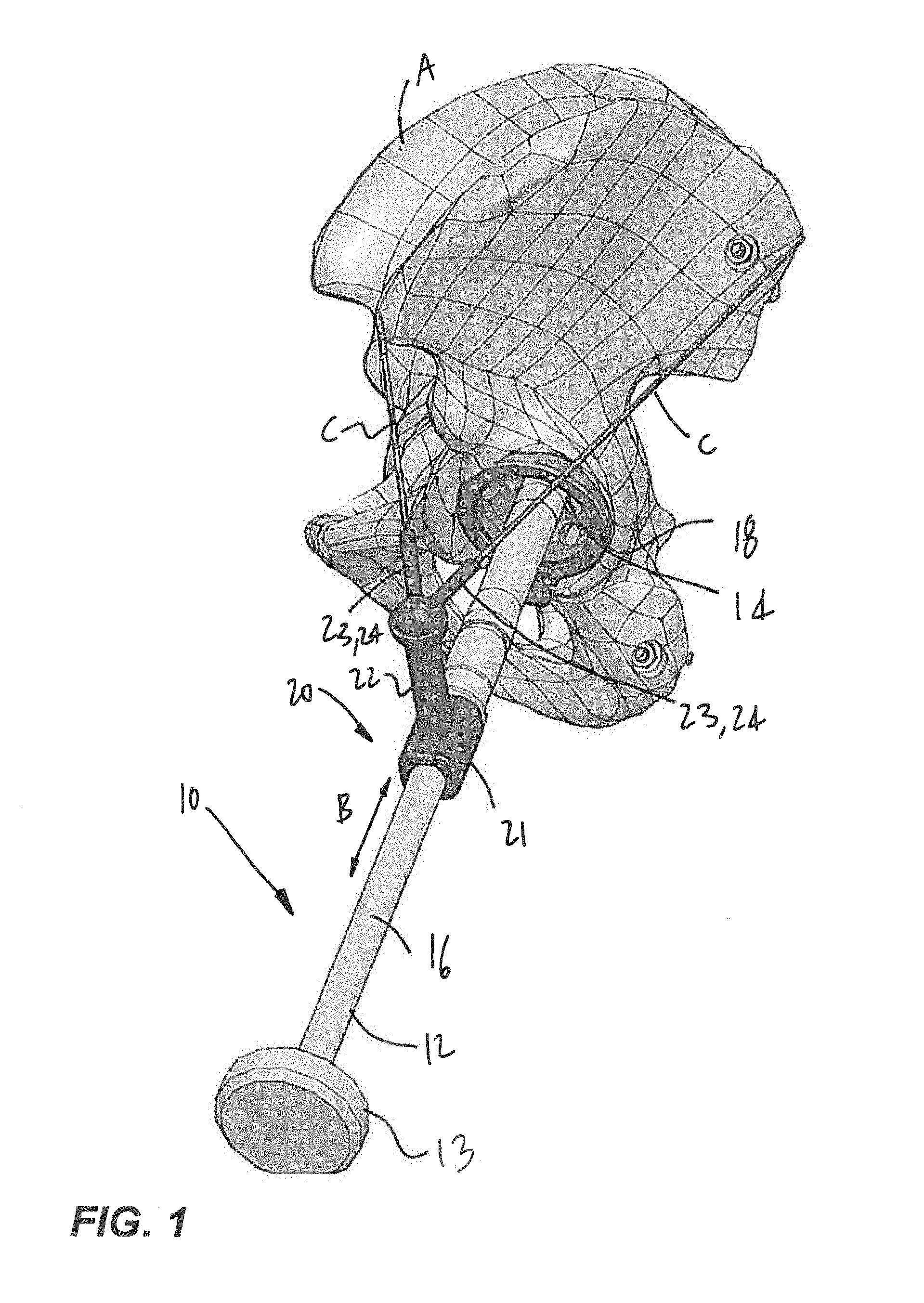
FIG. 1 is a perspective view of a cup impactor with visual guide in accordance with the present disclosure, relative to a pelvis;
FIG. 2 is a flow chart illustrating a method for creating a patient-specific visual guide for cup impactor and method for impacting the cup to a desired orientation;
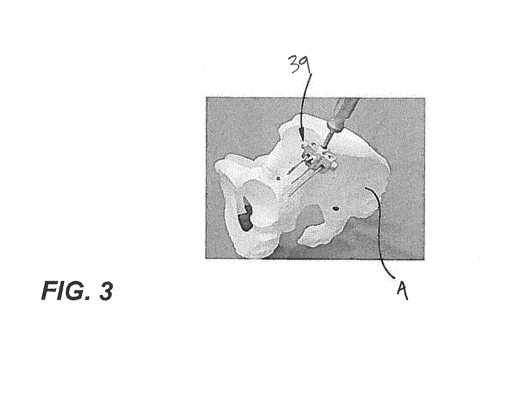
FIG. 3 is a perspective view of a block and Steinmann pins that may be used in part of the method of FIG. 2;
FIG. 4 is a perspective view of an embodiment of the visual guide of FIG. 1 in accordance with the present disclosure;
FIGS. 5A-5D illustrate a method of using a cup impactor with a patient specific block in accordance with the method of FIG. 2 of the present disclosure;
FIGS. 6A-6D illustrate a method of using a cup impactor with a patient specific block and a patient specific visual guide in accordance with the method of FIG. 2 of the present disclosure; and
FIGS. 7A-7C illustrate a method of using a cup impactor with a patient specific block in accordance with the method of FIG. 2 of the present disclosure.
DETAILED DESCRIPTION
Referring to the drawings and more particularly to FIG. 1, there is illustrated a cup impactor 10 equipped with a visual guide 20 in accordance with the present disclosure, rendering the assembly specific to the patient. More specifically, while the cup impactor 10 may be a generic cup impactor, the presence of the visual guide 20 thereon, which visual guide 20 has been specifically conceived and/or configured for the patient, renders the assembly patient-specific. Patient specific refers hereinafter to components that are fabricated in part or in whole based on anatomic data unique to the patient, obtained pre-operatively using imaging techniques, as detailed hereinafter. Accordingly, the cup impactor 10 may be accompanied by a file that includes the patient-specific relation between the anatomical landmarks and a desired acetabular cup orientation relative to the landmarks used for the fabrication of a patient-specific portion of the cup impactor 10. For instance, the file may be a virtual three-dimension model, vectorial information representative of geometrical data between landmarks and desired orientation, etc.
The cup impactor 10 illustrated in FIG. 1 is shown as having a handle 12 at the end of which is an impacting head 13. A cup coupler 14 is at an opposing end of the cup impactor 10, with the handle 12 and the cup coupler 14 being interrelated by an elongated shaft 16, with the handle 12 being part of the shaft 16 in the embodiment of FIG. 1. The shaft 16 is shown as being a straight shaft. However, other configurations are considered as well for the shaft 16, such as shaft with an offset section, etc, or with additional ergonomic features for being grasped, at the handle 12, as shown later on in embodiments of the cup impactor 10. The cup 18 is the frusto-spherical or hemispherical implant that is to be inserted in the acetabulum of the pelvis A. Various types of cups 18 may be used, including cups 18 subsequently requiring a liner in their cavity, etc. The cup coupler 14, which may have any common configuration, attaches to the cup 18 in a releasable fixed arrangement. For example, an axis of the shaft 16 may pass through the center of the cup 18, and the axis may also be normal to a plane of the rim of the cup 18. When the cup 18 is at the end of the cup coupler 14, the operator, holding on to the handle 12, may impact the impacting end 13 so as to drive the cup 18 into engagement in the acetabulum of the pelvis A. It is observed that the alignment of the shaft 16 during the impacting will have a direct impact on the orientation of the cup 18 in the pelvis A. Stated differently, the abduction and anteversion will depend on the orientation of the cup 18 once inserted in the pelvis A. It is therefore desired that the orientation of the shaft 16 be navigated just before the impacting and/or during the impacting, to guide the operator in driving the cup 18 in a desired orientation (i.e., to a desired abduction and anteversion).
For this purpose, the visual guide 20 is provided as a patient-specific guidance aid. According to one embodiment, shown in FIG. 1, the visual guide 20 has a sleeve 21 that is mounted to the shaft 16. It is also considered to have the sleeve 21 on the handle 12, or closer to the cup coupler 14. Moreover, other configurations are considered to hold the visual guide 20 to the cup impactor 10 as an alternative to the sleeve 21, including brackets with fasteners, projections on the cup impactor 10 and/or a combination of these possibilities. In an embodiment, the sleeve 21 may translate along the shaft 16 (forming a prismatic joint), as illustrated by B. It is contemplated to provide a biasing mechanism to ensure that the visual guide 20 returns to the position shown in FIG. 1. The translational degree of freedom of the prismatic joint arrangement would help the operator in evaluating the orientation of the cup 18 once implanted, before the cup 18 is fully implanted, as explained hereinafter.
A support 22 projects from the sleeve 21 in a direction generally transverse to the axis of the shaft 16. Arms 23 are at ends of the support 22 and each support a light source 24. The light sources 24 are of the type that can produce a visible linear light beam in the manner shown at C. The light sources 24 may be known as lasers, light pointers, laser pointers, coherent light emitters, etc and may typically be operated by batteries, or by any other power source. The visual guide 20 is configured, shaped and/or dimensioned taking into consideration a desired orientation of the cup 18, to point the light beams to two distinct landmarks on the pelvis A or associated with the pelvis A when the cup impactor 10 holds the cup 18 in the desired orientation of the cup 18. In the embodiment of FIG. 1, these landmarks may be the anterior superior iliac spine (ASIS) and the posterior superior iliac spine (PSIS), which are often visible when covered by skin due to their projecting shape and to the thinness of the skin, or which can easily be manually detected through skin.
It is observed from FIG. 1 that the light beams C lie in a plane in which the axis of the shaft 16 does not lie: that is a trigonometric condition for the assembly of the cup impactor 10 and the visual guide 20 to point to the two landmarks from the unique desired orientation of the shaft 16 when the cup 18 is in the acetabulum. While the visual guide 20 is shown as employing light sources 24 emitting light beams C, it is contemplated to use other technologies as well. For instance, the visual guide 20 may have a pair of rods projecting from the arms 23 of the support 22, which rods would be sized to have their free ends come into contact with the landmarks on the pelvis A.
Referring concurrently to FIGS. 1 and 2, there is shown a method 30 for creating the patient-specific visual guide 20 for the cup impactor 10 (or like cup impactor), and for subsequently navigating the cup impactor 10 to reach a desired orientation of the cup 18. While reference is made to the cup impactor 10 of FIG. 1, the method 30 could be performed using other types of cup impactors or cup positioning devices, with other shapes of visual guides 20.
According to 31, a desired acetabular cup orientation is determined pre-operatively, relative to the femur A. In an embodiment, images of the patient's pelvis are used to determine the desired acetabular cup orientation. There are numerous ways to obtain these images, for instance by using X-rays taken from two standpoints, by using CT-scanning, by magnetic resonance, even by taking points manually using tracking technology. These imaging techniques may allow an operator to determine the cup orientation from a three-dimensional (3D) model representative of the patient's pelvis, and various techniques have been devised to model the pelvis in 3D with suitable precision. Using the images or model, an operator may determine the desired abduction and anteversion angles, as well as the center of rotation of the acetabulum, as part of a desired acetabular cup orientation. Moreover, using the images or 3D model, the operator establishes the position of the given landmarks (e.g., ASIS and PSIS as in FIG. 1) relative to the desired acetabular cup orientation. The information acquired and established in 31 may include the 3-axis distance between the landmarks and a center of rotation of the acetabulum, and an orientation of the cup 18 relative to these two landmarks. Other data that may be used is the skin thickness at the landmarks. The orientation of the cup 18 may be defined through an axis of the cup 18 normal to the plane in which lies the rim of the cup 18, the normal passing through the center of the cup 18. Other definitions of the cup orientation are contemplated as well.
In 32, with the desired acetabular cup orientation obtained in 31 relative to the pelvis (i.e., the landmarks and center of rotation), the required geometry of the visual guide 20 may be determined and this may include consideration of the type of cup implant 18 used. The geometry of the visual guide 20 is selected such that, once the cup impactor 10 and visual guide 20 are arranged in the manner shown in FIG. 1, with the light sources 24 being turned on, the selected landmarks will be targeted by the light beams C of the light sources 24. The spatial relation between the cup impactor 10/visual guide 20 and the pelvis A, based on the measurement taken in 31, ensure that only a proper alignment including the cup implant 18 in the acetabulum of the femur A, namely to the desired acetabular cup orientation, will result in the landmarks being lit up. Hence, the patient-specific visual guide 20 for cup impactor may be created based on the information found in step 31.
33 of method 30 is performed intra-operatively and is executed after the acetabulum has been resurfaced or when the acetabulum is ready to received the cup 18 therein. Hence, in 33, the cup impactor 10 has the cup 18 at its end in the manner shown in FIG. 1, for the cup 18 to be implanted. The cup impactor 10 also has the visual guide 20 thereon. In the embodiment of FIG. 1, the light sources 24 are turned on and the cup impactor 10 is positioned in the manner shown in FIG. 1, with the cup 18 seated in the acetabulum, but not yet impacted therein, thereby forming a spherical like-joint allowing rotations of the cup impactor 10, in two or three rotational degrees of freedom. At that moment, the operator is required to properly orient the impactor 10--i.e., rotate the impactor 10 in up to three degrees of freedom--while keeping the cup 18 seated in the acetabulum, until the light beams C illuminate the planned landmarks.
In the preparation of the pelvis leading to 33, it may be desired for the operator to place target stickers or to mark the soft tissue covering the planned landmarks to facilitate their subsequent targeting with the visual guide 20.
Once the landmarks are targeted by the visual guide 20 while the cup 18 is seated in the acetabulum and the operator is satisfied with the orientation and the alignment, the cup 18 may be impacted to desired orientation as identified at 34.
As mentioned previously, the sleeve 21 may include a prismatic joint. The prismatic joint of the sleeve 21 may help in confirming the proper orientation during the impacting until the cup 18 is implanted, considering that the cup 18 will move into engagement into the acetabulum and hence the visual guide 20 will change its position in the process. As such, the movement permitted by the prismatic joint of the sleeve 21 may be the equivalent of the impacting depth. Therefore, the operator may displace the visual guide 20 against the biasing mechanism to confirm the alignment of the light sources 24 once the impacting of the cup 18 has begun. Alternatively, the reverse process is considered as well, in which the operator in 33 may need to displace the sleeve 21 along the shaft 16 when the impacting has not begun, to align the visual guide 20 with the landmarks.
Still referring to FIG. 2, as an alternative to creating the cup impactor 10 with the patient-specific visual guide 20, a generic visual guide 20 may be used that is not specifically designed for the patient, using instead a patient-specific block. In FIG. 2, 35 is done instead of 32. 35 pertains to the creation of the patient-specific block. The patient-specific block is created as a function of the pre-operative acetabular cup orientation that has been determined in 31, using similar data, such as the spatial relation, the center of rotation of the acetabulum, the desired abduction and anteversion angles relative to the axis of the cup 18. The patient-specific block is a block featuring a surface that is contour-matching fabricated to sit perfectly on a given surface of the bone, based on the pre-operative planning of 31. Accordingly, by the high-accuracy interconnection between the patient-specific block and the bone when the patient-specific block is against the bone in complementary engagement, it is possible to have a visual guide (as 20 in FIG. 1) on the block at the precise location at which it would be on the cup impactor 10 in the desired alignment of 33 (knowing the manufacturers dimensions of cup impactors, etc).
According to 36, intra-operatively, a temporary alignment target is created. This is done for instance by securing Steinmann pins and a target block on the pelvis, in a region in which the visual guide is predicted to target. Such an arrangement of Steinmann pins and target block is generally shown at 39 in FIG. 3, but other bone screws and targets may also be used. In an embodiment, the block is typically adjustable in position and orientation to ensure that it is aligned with the illumination field of the visual guide 20. Hence, with the temporary alignment target secured to the bone, the light beams C of the visual guide 20 on the patient-specific block are turned on to create targets. These targets may be marked by stickers, markers, etc.
Then, the method returns to 33 using the temporary alignment targets obtained in 36 instead of landmarks, and the generic visual guide 20 on the cup impactor 10. Accordingly, 35 and 36 suggest using an intra-operatively added target that is calibrated using a patient-specific block, the patient-specific block replicating the position of a generic visual guide on the cup impactor in the desired cup orientation. This alternate sequence does not rely on landmarks hidden by soft tissue.
For the sake of clarity additional embodiments are provided in the following figures. The additional embodiments have similarities with the embodiment of FIGS. 1-3, whereby like elements will bear like reference numerals.
Referring to FIG. 4, an embodiment of the visual guide 20. The visual guide 20 is patient specific, as fabricated based on 31 and 32 of the method 30 of FIG. 2. The visual guide 20 in FIG. 4 has a pair of housings 40 conceived for the releasable connection of light sources therein. The housings 40 are interconnected to the cup impactor 10 by way of a body 41 and connector 42 interfacing the body 41 to the cup impactor 10.
The embodiment of the visual guide 20 is said to be patient specific, in that the geometry between the housings 40 and the connector 42 is shaped based on the patient's anatomy through steps 31 and 32 of FIG. 2. The housings 40 enable the use of generic light sources that can be snap-fitted to the visual guide 20, and subsequently be reused in other procedures (with adequate sterilization, etc).
Referring now to FIGS. 5A to 5D, a sequence of steps is illustrated and is representative of steps 31, 35, 36, 33 and 34 of the method 30 of FIG. 2. As shown in FIG. 5A, a patient specific block 50 is used as a result of 31 and 35. The patient specific block 50 is devised to be received in the acetabulum in a single alignment orientation, because of the patient specific contour flange 51 (or like projection) surrounding the frusto-spherical portion 52. The cup impactor 10 has its cup coupler 14 in the patient specific block 50. Accordingly, when the cup impactor 10 is coupled to the pelvis A in the manner shown in FIG. 5B, with the patient specific block 50 in the single alignment orientation, the cup impactor 10 is aligned for implanting the cup in the desired acetabular cup orientation.
Still as in FIG. 5B, light sources 53 in a generic visual guide 20 may be used to lit up two unplanned and/or arbitrary landmarks on the patient, and stickers 54 or temporary marking may be used to identify the landmarks for subsequent use, as in FIG. 5C. Referring to FIG. 5D, the cup impactor 10 may then be used with the cup 18 at its end to impact the cup 18 into the acetabulum, after having removed the patient specific block 50. The stickers 54 are used in conjunction with the light beams to guide the operator in keeping the cup impactor 10 aligned during impaction.
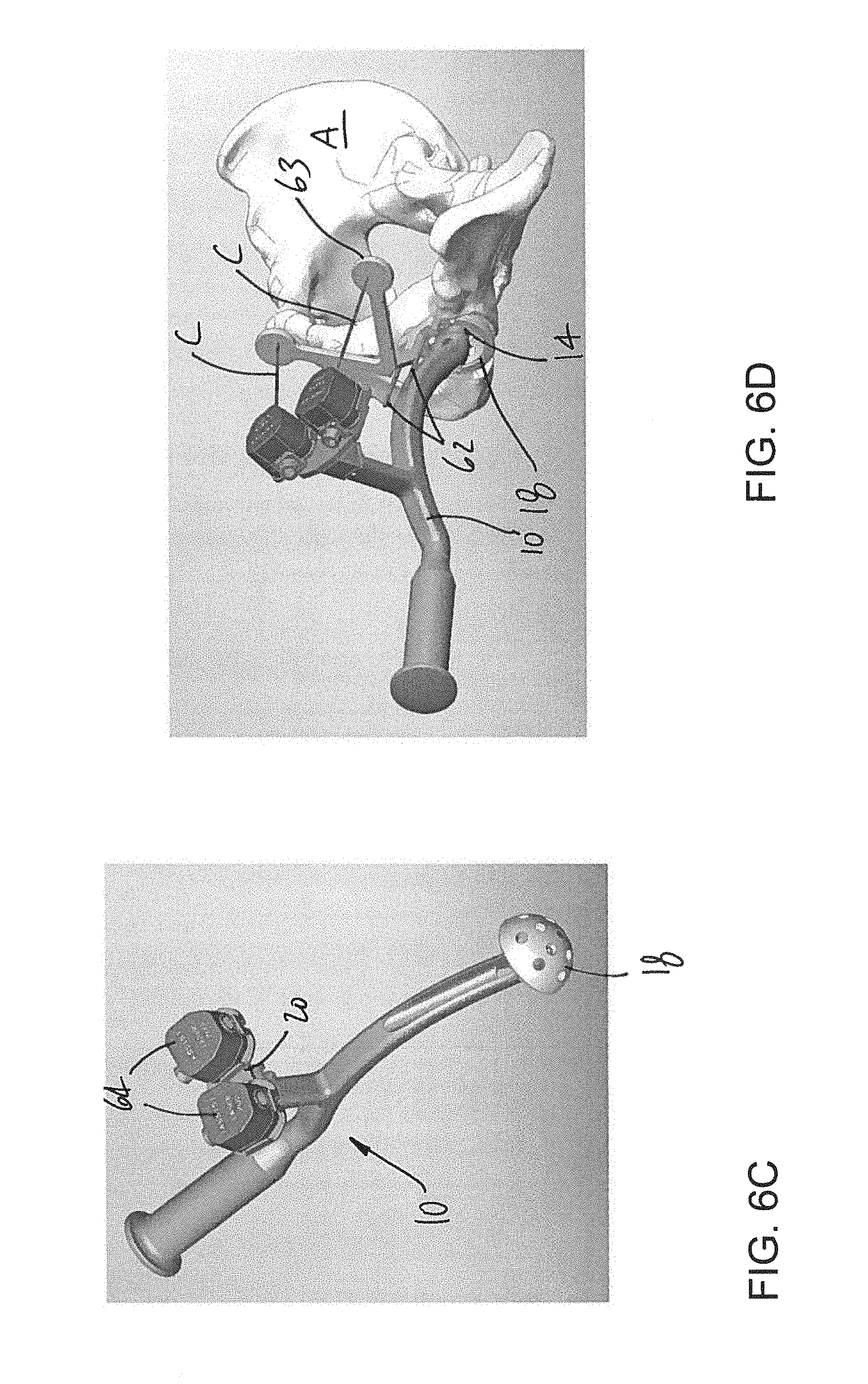
Referring now to FIGS. 6A to 6D, a sequence of steps is illustrated and is representative of steps 31-34, and 35-36 of the method 30 of FIG. 2, with the creating of a patient specific visual guide 20 and of a patient specific block 60. As shown in FIG. 6A, the patient specific block 60 is used as a result of 31 and 35. The patient specific block 60 is devised to be received in the acetabulum in a single alignment orientation, because of the patient specific contour surrounding a frusto-spherical portion. The patient specific block 60 further comprises a pair of guides 61 for guiding the positioning of pins 62 in the pelvis A, as in FIG. 6A. The spacing between the pins 62 is predetermined based on the geometry of a generic target board 63.
Referring to FIGS. 6C and 6D, the cup impactor 10 may then be used with the cup 18 at its end to impact the cup 10 into the acetabulum, with the patient specific visual guide 20 having light sources 64 used to lit up the two targets of the target board 63. The patient specific visual guide 20 may result from the steps 31 and 32 knowing the geometry of the target board 63 and its pre-planned orientation on the pelvis A. The orientation of the cup impactor 10 is adjusted with the cup 18 in the acetabulum until the light emitted by the light sources 64 is on the targets, at which point the cup 18 will be in the desired acetabular cup orientation.
Referring now to FIGS. 7A to 7C, a sequence of steps is illustrated and is representative of steps 31, 35, 36, 33 and 34 of the method 30 of FIG. 2. As shown in FIG. 7A, a patient specific block 70 is used as a result of 31 and 35. The patient specific block 70 is devised to be received in the acetabulum in a single alignment orientation, because of the patient specific contour flange 71 (or like projection) projecting from the frusto-spherical portion 72. The patient specific block 70 further comprises an arm 73 having a pin guide 74 at its end, the arm 73 being sized and the pin guide 74 being oriented such that a pin 75 may be connected to a predetermined landmark of the pelvis, such as the ASIS. As shown in FIG. 7C, the cup impactor 10 with cup 18 at its end may then use the pin 75 as visual guide or physical guide (with a sleeve 76) to remain in a desired orientation for the cup 18 to be implanted in its desired acetabular cup orientation. The sleeve 76 acts as a visual guide as it may not actually touch the pin 75 threaded through it. The pin 75 acts as a pair of landmarks, as it has an orientation and a position that result in the cup impactor 10 having a single possible orientation when guided by the pin 75 and seated in the acetabulum via the cup 18.
While the methods and systems described herein have been described and shown with reference to particular steps performed in a particular order, it will be understood that these steps may be combined, subdivided or reordered to form an equivalent method without departing from the teachings of the present invention. Accordingly, the order and grouping of the steps is not a limitation of the present invention.
Modifications and improvements to the above-described embodiments of the present invention may become apparent to those skilled in the art. The foregoing description is intended to be exemplary rather than limiting. For example, the landmarks may be on other parts of the body or on components other than the ones described, provided they remain during use in a relatively fixed relation relative to the pelvis A. The scope of the present invention is therefore intended to be limited solely by the scope of the appended claims.
* * * * *
D00000
D00001
D00002
D00003
D00004
D00005
D00006
D00007
D00008
D00009
XML
uspto.report is an independent third-party trademark research tool that is not affiliated, endorsed, or sponsored by the United States Patent and Trademark Office (USPTO) or any other governmental organization. The information provided by uspto.report is based on publicly available data at the time of writing and is intended for informational purposes only.
While we strive to provide accurate and up-to-date information, we do not guarantee the accuracy, completeness, reliability, or suitability of the information displayed on this site. The use of this site is at your own risk. Any reliance you place on such information is therefore strictly at your own risk.
All official trademark data, including owner information, should be verified by visiting the official USPTO website at www.uspto.gov. This site is not intended to replace professional legal advice and should not be used as a substitute for consulting with a legal professional who is knowledgeable about trademark law.