Adjusting device, in particular for adjusting a camshaft of an internal combustion engine
Gaisberg-Helfenberg , et al. July 9, 2
U.S. patent number 10,344,633 [Application Number 14/888,192] was granted by the patent office on 2019-07-09 for adjusting device, in particular for adjusting a camshaft of an internal combustion engine. This patent grant is currently assigned to Daimler AG. The grantee listed for this patent is Daimler AG. Invention is credited to Alexander Gaisberg-Helfenberg, Markus Lengfeld, Jens Meintschel, Thomas Stolk.
| United States Patent | 10,344,633 |
| Gaisberg-Helfenberg , et al. | July 9, 2019 |
Adjusting device, in particular for adjusting a camshaft of an internal combustion engine
Abstract
An adjusting device, in particular for adjustment of a camshaft of an internal combustion engine, is disclosed. The adjusting device includes a brake unit which has at least one brake disc and at least one electromagnet for actuating the brake unit. The electromagnet has a yoke and an armature formed separately from the brake disc, where the brake disc is disposed at least partially spatially between the yoke and the armature of the electromagnet.
| Inventors: | Gaisberg-Helfenberg; Alexander (Beilstein, DE), Lengfeld; Markus (Leutenbach, DE), Meintschel; Jens (Bernsdorf, DE), Stolk; Thomas (Kirchheim, DE) | ||||||||||
|---|---|---|---|---|---|---|---|---|---|---|---|
| Applicant: |
|
||||||||||
| Assignee: | Daimler AG (Stuttgart,
DE) |
||||||||||
| Family ID: | 50289626 | ||||||||||
| Appl. No.: | 14/888,192 | ||||||||||
| Filed: | March 15, 2014 | ||||||||||
| PCT Filed: | March 15, 2014 | ||||||||||
| PCT No.: | PCT/EP2014/000698 | ||||||||||
| 371(c)(1),(2),(4) Date: | October 30, 2015 | ||||||||||
| PCT Pub. No.: | WO2014/177238 | ||||||||||
| PCT Pub. Date: | November 06, 2014 |
Prior Publication Data
| Document Identifier | Publication Date | |
|---|---|---|
| US 20160069228 A1 | Mar 10, 2016 | |
Foreign Application Priority Data
| May 2, 2013 [DE] | 10 2013 007518 | |||
| Current U.S. Class: | 1/1 |
| Current CPC Class: | F01L 1/352 (20130101); F01L 2001/3522 (20130101) |
| Current International Class: | F01L 1/352 (20060101) |
| Field of Search: | ;123/90.11,90.15,90.17 |
References Cited [Referenced By]
U.S. Patent Documents
| 3317009 | May 1967 | Warwick |
| 4227783 | October 1980 | Drasch |
| 5490583 | February 1996 | Anderson |
| 5826683 | October 1998 | Murata |
| 6161659 | December 2000 | Maurice |
| 6457446 | October 2002 | Willmot |
| 2002/0038639 | April 2002 | Mae et al. |
| 10 2008 060 926 | Jun 2010 | DE | |||
| 10 2009 012 137 | Sep 2010 | DE | |||
| 102008060926 | Oct 2010 | DE | |||
| 2004-162565 | Jun 2004 | JP | |||
| 2014-528547 | Oct 2014 | JP | |||
| WO 2013/053415 | Apr 2013 | WO | |||
Other References
|
Machine Translation of DE102008060926A1. cited by examiner . Japanese Office Action issued in Japanese counterpart application No. 2016-510956 dated Sep. 27, 2016, with partial English translation (Six (6) pages). cited by applicant . PCT/EP2014/000698, International Search Report (PCT/ISA/220 and PCT/ISA/210) dated Apr. 24, 2014, with partial English translation, enclosing Written Opinion of the International Searching Authority (PCT/ISA/237) (Thirteen (13) pages). cited by applicant. |
Primary Examiner: Trieu; Thai Ba
Assistant Examiner: Edwards; Loren C
Attorney, Agent or Firm: Crowell & Moring LLP
Claims
The invention claimed is:
1. An adjusting device for adjustment of a camshaft of an internal combustion engine, comprising: a brake unit which has a rotary movable brake disc, wherein the rotary movable brake disc has a first friction surface on a first side of the rotary movable brake disc and a second friction surface on a second side of the rotary movable brake disc; and an electromagnet, wherein the brake unit can be actuated by the electromagnet; wherein the electromagnet is a pull magnet and has a yoke, a coil, and an armature formed separately from the brake disc, wherein the yoke is surrounded at least in a region by the coil, wherein the yoke is disposed immovably with respect to the coil and conducts a magnetic field of the coil, wherein the armature is a movably mounted magnetic conductor, and wherein the armature is pullable in a direction of the yoke by a force produced by the magnetic field of the coil; wherein the brake disc is disposed at least partially spatially between the yoke and the armature of the electromagnet; wherein the yoke has a first arm, a second arm, and a first curved portion that connects the first arm and the second arm and wherein the first and the second arms each have a third friction surface on a respective open end of the first and the second arms, wherein the third friction surface has a first brake lining; wherein the armature has a third arm, a fourth arm, and a second curved portion that connects the third arm and the fourth arm and wherein the third and the fourth arms each have a fourth friction surface on a respective open end of the third and the fourth arms, wherein the fourth friction surface has a second brake lining; wherein the respective friction surfaces of the first and the second arms of the yoke and the third and the fourth arms of the armature exert, in an activation state of the brake unit, a respective force on the brake disc and wherein the respective friction surfaces of the first and the second arms of the yoke are congruent with the respective friction surfaces of the third and the fourth arms of the armature.
2. The adjusting device according to claim 1, wherein the force of the armature and the force of the yoke are opposed to one another.
3. The adjusting device according to claim 1, wherein the yoke and the armature are disposed on opposite sides of the brake disc.
4. The adjusting device according to claim 1, wherein the brake disc is formed at least in a region of the first and the second friction surfaces of the brake disc from a ferromagnetically soft material.
5. The adjusting device according to claim 1, wherein the brake disc has an insulation region which is formed from a magnetically non-conductive material.
6. The adjusting device according to claim 5, wherein the brake disc has a spoke in the insulation region.
7. The adjusting device according to claim 1, further comprising a restoring element, wherein the restoring element provides a force on the yoke and the armature which is opposed to a force exerted by the yoke and the armature on the brake disc.
8. A valve train device for an internal combustion engine, comprising: a camshaft; and an adjusting device, wherein the camshaft is adjustable by the adjusting device and wherein the adjusting device comprises: a brake unit which has a rotary movable brake disc, wherein the rotary movable brake disc has a first friction surface on a first side of the rotary movable brake disc and a second friction surface on a second side of the rotary movable brake disc; and an electromagnet, wherein the brake unit can be actuated by the electromagnet; wherein the electromagnet is a pull magnet and has a yoke, a coil, and an armature formed separately from the brake disc, wherein the yoke is surrounded at least in a region by the coil, wherein the yoke is disposed immovably with respect to the coil and conducts a magnetic field of the coil, wherein the armature is a movably mounted magnetic conductor, and wherein the armature is pullable in a direction of the yoke by a force produced by the magnetic field of the coil; wherein the brake disc is disposed at least partially spatially between the yoke and the armature of the electromagnet; wherein the yoke has a first arm, a second arm, and a first curved portion that connects the first arm and the second arm and wherein the first and the second arms each have a third friction surface on a respective open end of the first and the second arms, wherein the third friction surface has a first brake lining; wherein the armature has a third arm, a fourth arm, and a second curved portion that connects the third arm and the fourth arm and wherein the third and the fourth arms each have a fourth friction surface on a respective open end of the third and the fourth arms, wherein the fourth friction surface has a second brake lining; wherein the respective friction surfaces of the first and the second arms of the yoke and the third and the fourth arms of the armature exert, in an activation state of the brake unit, a respective force on the brake disc and wherein the respective friction surfaces of the first and the second arms of the yoke are congruent with the respective friction surfaces of the third and the fourth arms of the armature.
Description
BACKGROUND AND SUMMARY OF THE INVENTION
The invention relates to an adjusting device, in particular for adjustment of a camshaft of an internal combustion engine.
An adjusting device is already known for adjustment of a camshaft of an internal combustion engine, with a brake unit which has at least one brake disc, and with at least one electromagnet for actuating the brake unit, the electromagnet having a yoke and an armature formed separately from the brake disc.
The object of the invention in particular is to provide a particularly reliable brake unit for an adjusting device, in particular for adjusting a camshaft of an internal combustion engine.
The starting point for the invention is an adjusting device, in particular for adjustment of a camshaft of an internal combustion engine, with a brake unit which has at least one brake disc, and with at least one electromagnet for actuating the brake unit, the electromagnet having a yoke and an armature formed separately from the brake disc.
It is proposed that the brake disc is disposed at least partially spatially between the yoke and the armature of the electromagnet. Due to an armature formed separately from the brake disc, the brake disc may be designed to be particularly thin, so that the inertia of the brake disc as well as a time constant of the controller can be reduced. Because the brake disc is disposed spatially between the yoke and the armature, the electromagnet can be designed as a pull magnet which has few parts in particular by comparison with a push magnet, so that a particularly compact, cost-effective and reliable brake unit can be provided. A "coil" of an electromagnet should be understood in particular to be a component with a wound electrical conductor which is provided so that, at least in an activation state of the brake unit, an electric current flows through it and a magnetic field is generated. A "yoke" of an electromagnet should be understood in particular to be a magnetic conductor which is surrounded at least in a region by the coil and which is disposed immovably with respect to the coil and in particular is provided in order to conduct the magnetic field of the coil. An "armature" of an electromagnet should be understood in particular to be a movably mounted magnetic conductor which is provided in order to be moved by a force produced by the magnetic field of the coil. "Provided" should be understood in particular to mean especially `designed,` `equipped,` and/or `disposed.`
Furthermore, it is proposed that the armature and the yoke each have at least one friction surface which are each provided in order to exert, at least in an activation state of the brake unit, a force on the brake disc. Because both the yoke and the armature exert a force on the brake disc, a particularly effective braking device can be provided. A "friction surface" should be understood in particular to be a surface which is provided in order to be, at least in an activation state of the brake unit, in contact with a corresponding surface of the brake disc, so that a braking force is generated which counteracts a rotary movement of the brake disc. The friction surface preferably has a brake lining which is provided in order to increase the generated braking force. The friction surface of the armature and the friction surface of the yoke are preferably disposed on different sides of the brake disc in a mirror image and facing one another relative to the brake disc. Particularly preferably the friction surfaces are congruent with one another, i.e. they have an identical shape.
Furthermore it is proposed that the forces exerted on the brake disc by the yoke and the armature are opposed to one another. In this way, axial forces on the brake disc can be avoided. Any effects of tolerances, thermal expansion and occurring wear can be compensated for and the durability of the brake unit can be increased. The fact that the forces exerted on the brake disc "are opposed to one another" should in particular be understood in this context to mean that, in an activation state of the brake unit, these forces impinge on two directly opposing surfaces of the brake disc and are oriented antiparallel relative to one another. The brake disc is preferably supported so as to be axially movable, so that the force of the yoke acts as an opposing force to the force of the armature acts, i.e. the force of the yoke and the force of the armature have the same value.
Furthermore it is proposed that the yoke and the armature are disposed on opposing sides of the brake disc. As a result a residual gap between the yoke and the armature is unnecessary for compensation for tolerances and wear, and the yoke, the brake disc and the armature are in contact with one another at an operating point of the electromagnet, so that the degree of efficiency of the brake is increased. The fact that the yoke and the armature are disposed on "opposite sides" of the brake disc should in particular be understood to mean that they lie opposite one another in the axial direction with regard to the brake disc and have the same radial spacing from the axis of the brake disc, and a radius from the axis to the yoke is disposed parallel to a radius from the axis to the armature.
Furthermore it is proposed that the brake disc has at least one annular friction surface which, at least in an activation state of the electromagnet, at least in a section is penetrated at least substantially in a straight line by a magnetic flux. In this way the brake disc can be of particularly lightweight construction as the brake disc does not have to perform the function of a magnetic armature, so that the inertia of the brake disc can be decreased and a time constant when adjusting the camshaft can be reduced. The fact that the brake disc is penetrated "in a straight line by a magnetic flux" should in particular be understood to mean that, in an activation state of the brake unit, the yoke and the armature have a magnetic circuit, i.e. that a magnetic flux through a cross-section of the armature is at least substantially equal to a magnetic flux through a cross-section of the yoke. A radial component of the magnetic flux in the brake disc is preferably less than 10% of an axial component of the magnetic flux and particularly advantageously less than 5% of the axial component of the magnetic flux.
Furthermore it is proposed that the brake disc is formed at least in the region of the friction surface from a ferromagnetically soft material. In this way a magnetic resistance of the brake unit can be decreased and the degree of efficiency of the brake unit can be increased. Moreover a permanent magnetization of the brake disc and thus an undefined residual brake torque can be avoided in a non-active state of the brake unit. A "ferromagnetic material" should in particular be understood to be a material which has a high magnetic conductivity. The material preferably has a magnetic permeability greater than 10000, particularly advantageously the material has a magnetic permeability greater than 100000. A "ferromagnetically soft material" should in particular be understood to be a material which has a low residual magnetization and thus a low coercive field strength. The coercive field strength is preferably less than 2 A/m, particularly advantageously less than 1 A/m.
Furthermore it is proposed that the brake disc has at least one second friction surface and an insulation region which spatially separates the friction surfaces and is formed from a magnetically non-conductive material. As a result a radial component of the magnetic flux in the brake disc and thus a unilateral force between the yoke and the brake disc can be reduced. In this context an insulation region should be understood in particular to be an annular region which is disposed in the radial direction between two annular friction surfaces of the brake disc. A "magnetically non-conductive material" should be understood to be a diamagnetic or paramagnetic material, for example austenitic stainless steel or aluminum.
Furthermore it is proposed that the brake disc has at least one spoke in the insulation region. As a result a particularly lightweight brake disc can be provided and a radial component of the magnetic flux can be reduced. In principle it is also conceivable that the brake disc is closed in the insulation region and is particularly thin.
Furthermore it is proposed that the armature of the electromagnet is designed as a hinged armature. In this way a particularly simply designed and cost-effective brake unit can be provided. A "hinged armature" should be understood to be an armature which is rotatably mounted on one end and has an axis of rotation which is disposed in a circumferential direction of the brake disc. The hinged armature is preferably mounted in the yoke of the electromagnet and has a planar arm which is disposed substantially parallel to the brake disc.
Furthermore it is proposed that the yoke of the electromagnet has at least one arm which covers the brake disc in the radial direction. In this way a particularly compact adjusting device can be provided. The arm of the yoke has on an open end a bearing in which the hinged armature of the brake unit is supported. In principle it is conceivable that the yoke has further arms which are preferably disposed offset from one another in a circumferential direction of the brake disc.
Furthermore a restoring element is proposed which is provided in order to exert a force on the yoke and the armature which is opposed to a force exerted by the yoke and the armature on the brake disc. In this way a residual brake torque can be minimized, so that the precision and reliability are increased when the adjusting device is used. A restoring element should be understood in particular to be an elastically deformable spring element which provides a tensioning force and is disposed functionally between the yoke and the armature.
Furthermore a valve train device for an internal combustion engine is proposed, with at least one camshaft and an adjusting device according to the invention which is provided for adjustment of the at least one camshaft. The controllability of the internal combustion engine can be improved by the use of the adjusting device in a valve train device.
Further advantages can be seen from the following description of the drawings. Two exemplary embodiments of the invention are shown in FIGS. 1 to 3. FIGS. 1 to 3, the description of the drawings and the claims contain numerous features in combination. Expediently, the person skilled in the art will also consider the features singly and combine them to form meaningful further combinations.
BRIEF DESCRIPTION OF THE DRAWINGS
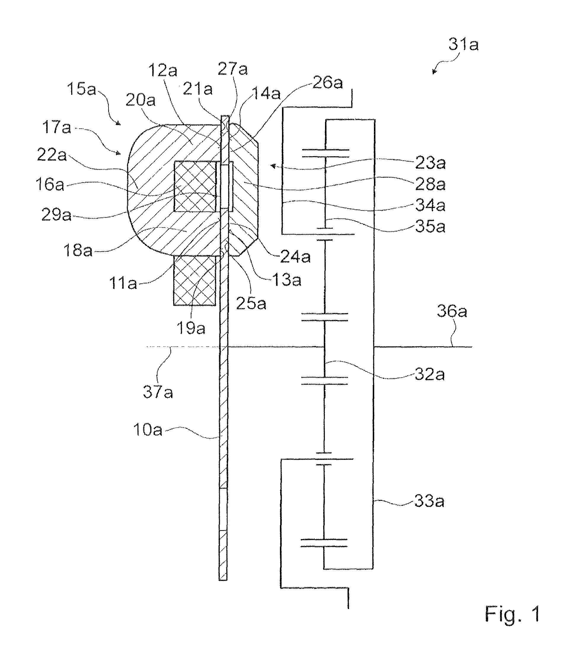
FIG. 1 a longitudinal section of an adjusting device with a brake unit and an electromagnet and a transmission in a schematic representation,
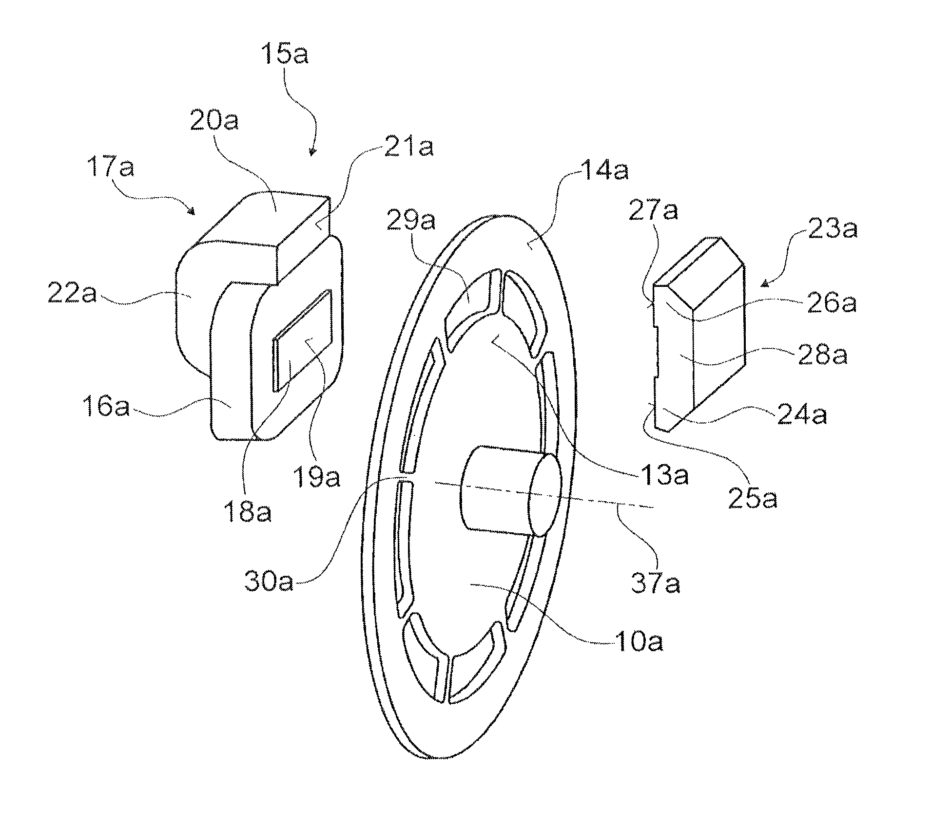
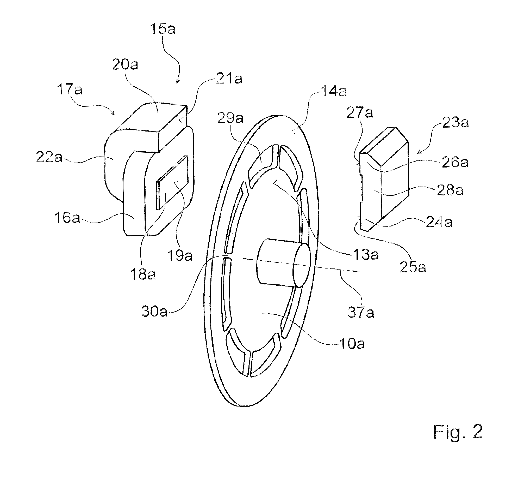
FIG. 2 an exploded representation of the brake unit and the electromagnet of the adjusting device, and
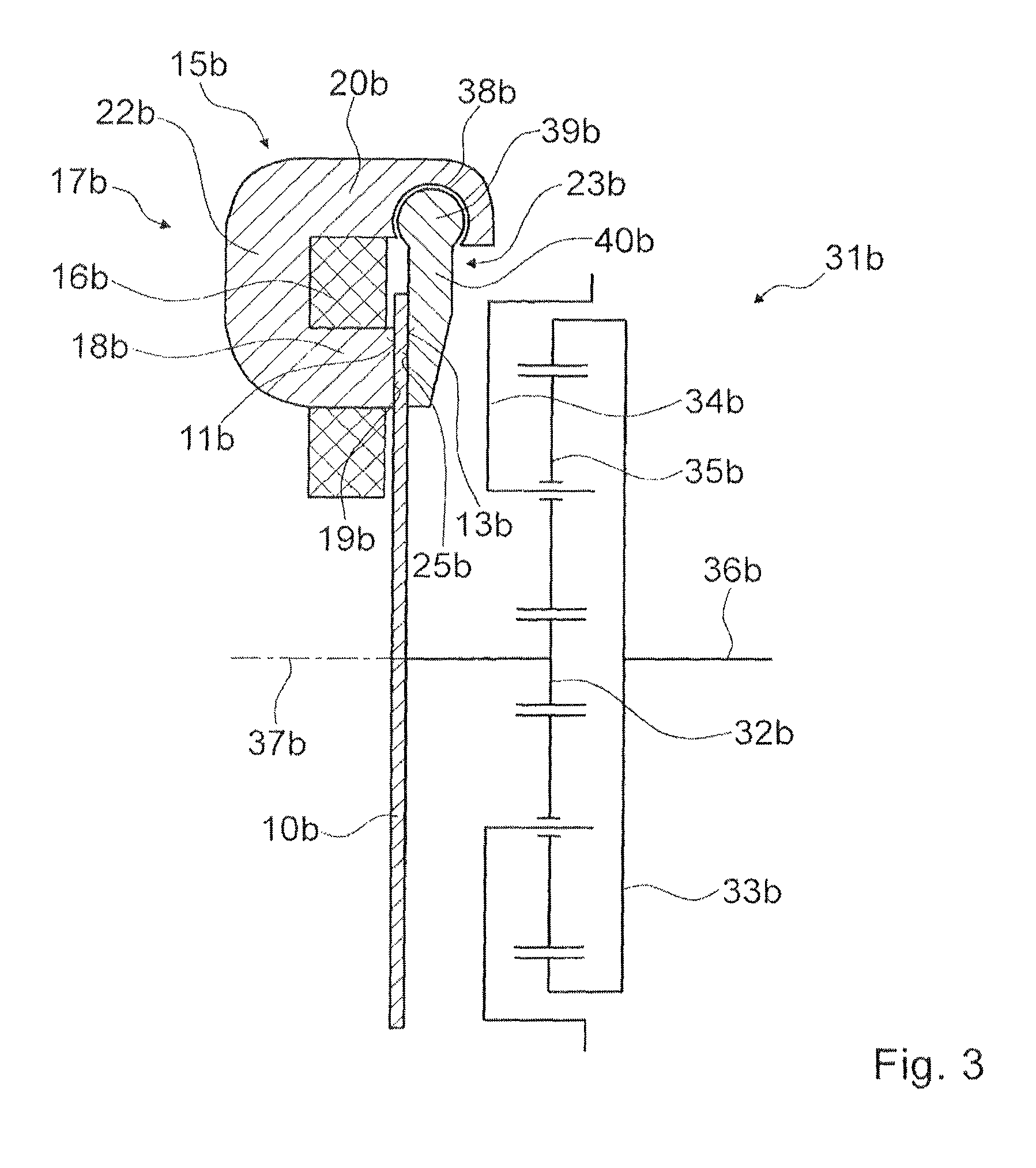
FIG. 3 a longitudinal section of the adjusting device with a brake unit and an electromagnet with hinged armature.
DETAILED DESCRIPTION OF THE DRAWINGS
FIGS. 1 and 2 show schematically a valve train device for an internal combustion engine, with a 3-shaft minus summation gear system 31a. The valve train device comprises an adjusting device for adjustment of a camshaft 36a of the internal combustion engine, with a brake unit and an electromagnet 15a for actuating the brake unit. The 3-shaft minus summation gear system 31a comprises a sun gear 32a, a ring gear 33a and a planetary gear support 34a. The planetary gear support 34a carries planetary gears 35a on a circular path. The planetary gears 35a mesh with the sun gear 32a and with the ring gear 33a. The planetary gears 35a are rotatably supported on the planetary gear support 34a. The ring gear 33a is coupled to a camshaft 36a. The planetary gear support 34a is coupled to a crankshaft which is not shown in greater detail. The sun gear 32a is coupled to the brake unit.
The brake unit has a brake disc 10a. The brake disc 10a is designed as a circular surface and has an axis 37a which is disposed perpendicular to the circular surface.
The electromagnet 15a has a coil 16a, a yoke 17a and an armature 23a. The yoke 17a of the electromagnet 15a is formed from laminated material. The yoke 17a is in the form of a rectangular bar bent in a U shape. The yoke 17a has a first arm 18a and a second arm 20a and a curve 22a. The arms 18a, 20a are disposed parallel to one another. The curve 22a of the yoke 17a connects the two arms 18a, 20a. The arms 18a, 20a of the yoke 17a each have a rectangular, planar friction surface 19a, 21a on their respective open end. The electromagnet 15a is disposed eccentrically with respect to the axis 37a of the brake disc 10a. The friction surfaces 19a, 21a of the arms 18a, 20a are disposed parallel to the brake disc 10a. The arms 18a, 20a each have an axis. The axes of the arms 18a, 20a are disposed parallel to one another and parallel to the axis 37a of the brake disc 10a. The intersection points of the axes of the arms 18a, 20a with the brake disc 10a are disposed on a radius of the brake disc 10a. The first arm 18a has a smaller spacing from the axis 37a of the brake disc 10a than the second arm 20a. The first arm 18a and the second arm 20a are disposed in the radial direction on the same side of the axis 37a of the brake disc 10a.
The coil 16a of the electromagnet 15a is designed as an annular wire winding. The coil 16a has an axis which is disposed congruent with the axis of the first arm 18a. The coil 16a surrounds the first arm 18a of the yoke 17. In principle it is conceivable that the coil 16a of the second arm 18a, the curve 22a or the entire yoke 17a. The coil 16a and the yoke 17a are disposed immovably relative to one another. The coil 16a is provided so that an electric current flows through it and a magnetic flux is generated in the yoke 17a and in the armature 23a. The yoke 17a and the coil 16a of the electromagnet 15a are mounted firmly with respect to the adjusting device.
The armature 23a of the electromagnet 15a is formed separately from the brake disc 10a. The armature 23a is provided in order, in an activation state of the electromagnet 15a, to close a magnetic circuit together with the yoke 17a. The armature 23a is formed from laminated material. The armature 23a is in the form of a rectangular bar bent in a U shape. The armature 23a has a first arm 24a and a second arm 26a and a curve 28a. The arms 24a, 26a are disposed parallel to one another. The curve 28a of the armature 23a connects the two arms 24a, 26a. A ratio of the length of the arm 24a, 26a to the spacing of the arms 24a, 26a is approximately 1/15. The arms 24a, 26a of the armature 23a each have a rectangular, planar friction surface 25a, 27a on their respective open end. The friction surfaces 25a, 27a of the arms 24a, 26a are disposed parallel to the brake disc 10a. The arms 24a, 26a each have an axis. The axes of the arms 24a, 26a are disposed parallel to one another and perpendicular to the friction surfaces 25a, 27a of the arms 24a, 26a. The axes of the arms 24a, 26a are disposed parallel to the axis 37a of the brake disc 10a. The intersection points of the axes of the arms 24a, 26a with the brake disc 10a are disposed on a radius of the brake disc 10a. The first arm 24a has a smaller spacing from the axis 37a of the brake disc 10a than the second arm 26a. The friction surfaces of the arms 24a, 26a of the armature 23a are congruent with the friction surfaces 19a, 21a of the arms 18a, 20a of the yoke 17a.
The yoke 17a and the armature 23a of the electromagnet 15a are disposed on opposing sides of the brake disc 10a. The brake disc 10a is disposed in the axial direction between the yoke 17a and the armature 23a of the electromagnet 15a. The yoke 17a and the armature 23a of the electromagnet 15a are disposed on a plane of the brake disc 10a in mirror image to one another. The friction surface 19a of the first arm 18a of the yoke 17a is disposed, relative to the plane of the brake disc 10a, opposite the friction surface 25a of the first arm 24a of the armature 23a and the friction surface 21a of the second arm 20a of the yoke 17 is disposed, relative to the plane of the brake disc 10a, opposite the friction surface 27a of the second arm 26a of the armature 23a. The first arm 24a of the armature 23a is disposed with the same spacing from the axis 37a of the brake disc 10a as the first arm 18a of the yoke 17a. The second arm 26a of the armature 23a is disposed with the same spacing from the axis 37a of the brake disc 10a as the second arm 20a of the yoke 17a.
The armature 23a is axially movable and mounted in a rotationally fixed manner with respect to the axis 37a of the brake disc 10a. The yoke 17a of the electromagnet 15a is provided in order in an activation state of the brake unit to conduct a magnetic field which is generated by the coil 16a and which exerts a force on the armature 23a of the electromagnet 15a, so that the armature 23a is pulled in the direction of the yoke 17a and the brake disc 10a disposed between the yoke 17a and the armature 23a. In the activation state of the electromagnet 15a the friction surfaces 25a, 27a of the armature 23a and the friction surfaces 19a, 21a of the yoke 17a are in contact with the brake disc 10a and in each case exert a force on the brake disc 10 which produces a braking force which counteracts a rotation of the brake disc 10a. The force which the yoke 17a exerts on the brake disc 10a is opposed to the force which the armature 23a exerts on the brake disc 10a. In principle it is conceivable that a permanent magnet is disposed in the yoke 17a or in the armature 23a, so that a defined braking action can also be achieved in a de-energized state.
The brake disc 10a has a first side which faces the yoke 17a of the electromagnet 15a, and the brake disc 10a has a second side which faces the armature 23a of the electromagnet 15a. The brake disc 10a is mounted so as to be axially movable. A ratio of the thickness of the brake disc 10a to the thickness of the curve 28a of the armature 23a is approximately one third.
The brake disc 10a has an annular first friction surface 11a on the first side. The first friction surface 11a is disposed concentrically with respect to the brake disc 10a. The first friction surface 11a has an inner radius which corresponds to a spacing of the first arm 18a of the yoke 17a from the axis 37a of the brake disc 10a. The first friction surface 11a has a width which corresponds to a thickness of the first arm 18a of the yoke 17a. The brake disc 10a has an annular second friction surface 12a on the first side. The second friction surface 12a is disposed concentrically with respect to the brake disc 10a. The second friction surface 12a has an inner radius which corresponds to a spacing of the second arm 20a of the yoke 17a from the axis 37a of the brake disc 10a. The second friction surface 12a has a width which corresponds to a thickness of the second arm 20a of the yoke 17a.
The brake disc 10a has an annular third friction surface 13a on the second side. The third friction surface 13a is disposed concentrically with respect to the brake disc 10a. The third friction surface 13a has an inner radius which corresponds to a spacing of the first arm 24a of the armature 23a from the axis 37a of the brake disc 10a. The third friction surface 13a has a width which corresponds to a thickness of the first arm 24a of the armature 23a. The brake disc 10a has an annular fourth friction surface 14a on the second side. The fourth friction surface 14a is disposed concentrically with respect to the brake disc 10a. The fourth friction surface 14a has an inner radius which corresponds to a spacing of the second arm 26a of the armature 23a from the axis 37a of the brake disc 10a. The fourth friction surface 14a has a width which corresponds to a thickness of the second arm 26a of the armature 23a.
The first friction surface 11a and the third friction surface 13a of the brake disc 10a are designed to be congruent with one another. They are disposed opposite one another on the brake disc 10a. In a region of the first friction surface 11a and the third friction surface 13a the brake disc 10a is formed from a ferromagnetically soft material. The second friction surface 12a and the fourth friction surface 14a of the brake disc 10a are designed to be congruent with one another. They are disposed opposite one another on the brake disc 10a. In a region of the second friction surface 12a and the fourth friction surface 14a the brake disc 10a is made from a ferromagnetically soft material.
It is conceivable that the friction surfaces 11a, 12a, 13a, 14a of the brake disc 10a have a brake lining made of magnetically conductive material. It is also conceivable that the friction surfaces 19a, 21a of the yoke 17a and the friction surfaces 25a, 27a of the armature 23a have a brake lining which is formed from magnetically conductive material.
In an activation state of the electromagnet 15a the yoke 17a and the armature 23a have a magnetic flux which forms a magnetic circuit. The flux penetrates the brake disc 10a substantially in a straight line in the region of the first friction surface 11a and the third friction surface 13a in an axial direction. The flux penetrates the brake disc 10a substantially in a straight line in the region of the first friction surface 12a and the fourth friction surface 14a in the opposite direction.
In the radial direction between the first friction surface 11a and the second friction surface 12a and/or between the third friction surface 13a and the fourth friction surface 14a the brake disc 10a has an annular insulation region 29a. The insulation region 29a spatially separates the first friction surface 11a from the second friction surface 12a, as well as the third friction surface 13a from the fourth friction surface 14a. The insulation region 29a of the brake disc 10a is formed from a magnetically non-conductive material. The insulation region 29a of the brake disc 10a has eight spokes 30a. The spokes 30a extend in the radial direction and connect the region of the first friction surface 11a and the third friction surface 13a to the region of the second friction surface 12a and the fourth friction surface 14a.
A further exemplary embodiment of the invention is shown in FIG. 3. The following descriptions are limited substantially to the differences between the exemplary embodiments wherein, with regard to components, features and functions which are the same, reference may be made to the description of the exemplary embodiment according to FIGS. 1 and 2. In order to distinguish the exemplary embodiments, the letter a in the reference signs of the exemplary embodiment in FIGS. 1 and 2 is replaced by the letter b in the reference signs of the exemplary embodiment according to FIG. 3. With regard to components with the same references, in particular with regard to components with the same reference signs, reference may in principle be made to the drawings and/or the description of the exemplary embodiment according to FIGS. 1 and 2.
FIG. 3 shows schematically a valve train device for an internal combustion engine, with a 3-shaft minus summation gear system 31b. The valve train device comprises an adjusting device for adjustment of a camshaft 36b of the internal combustion engine, with a brake unit and an electromagnet 15b for actuating the brake unit. The 3-shaft minus summation gear system 31b comprises a sun gear 32b, a ring gear 33b and a planetary gear support 34b. The planetary gear support 34b carries planetary gears 35b on a circular path. The planetary gears 35b mesh with the sun gear 32b and with the ring gear 33a. The planetary gears 35b are rotatably supported on the planetary gear support 34b. The ring gear 33b is coupled to a camshaft 36b. The planetary gear support 34b is coupled to a crankshaft which is not shown in greater detail. The sun gear 32b is coupled to the brake unit. The brake disc 10b is designed as a circular surface and has an axis 37b which is disposed perpendicular to the circular surface.
The electromagnet 15b has a coil 16b, a yoke 17b and an armature 23b. The yoke 17b is in the form of a rectangular bar bent in a U shape. The yoke 17b has a first arm 18b and a second arm 20b and a curve 22b. The arms 18b, 20b are disposed parallel to one another. The curve 22b of the yoke 17b connects the two arms 18b, 20b. The arms 18b, 20b each have an axis. The axes of the arms 18b, 20b are disposed parallel to one another and parallel to the axis 37b of the brake disc 10b. The first arm 18b has a smaller spacing from the axis 37b of the brake disc 10b than the second arm 20b. The first arm 18b of the yoke 17b has a rectangular, planar friction surface 19a, 19b on its open end. The electromagnet 15b is disposed eccentrically with respect to the axis 37b of the brake disc 10b. The friction surface 19b of the first arm 18b is disposed parallel to the brake disc 10b. The second arm 20b has a length which is greater by approximately one third than the second arm 18b. The second arm 20b covers the brake disc 10b in the radial direction.
The coil 16b of the electromagnet 15b is designed as an annular wire winding. The coil 16b has an axis which is disposed congruent with the axis of the first arm 18b. The coil 16b surrounds the first arm 18b of the yoke 17b. The yoke 17b and the coil 16b of the electromagnet 15b are disposed so as to be immovable with respect to one another and are mounted firmly with respect to the adjusting device.
The armature 23b of the electromagnet 15b is formed separately from the brake disc 10b. The armature 23b is provided in order, in an activation state of the electromagnet 15b, to close a magnetic circuit together with the yoke 17a. The armature 23b of the electromagnet 15b is formed as a hinged armature. The armature 23b has a bearing region 39b and an arm 40b. The bearing region 39b of the armature 23b is in the form of a circular cylinder. The arm 40b of the armature 23b is substantially cuboid. At a transition to the bearing region 39b the arm 40b of the armature 23b has a thickness of approximately two thirds of a diameter of the bearing region 39b. On an open end of the arm 40b the arm 40b tapers to approximately half of its thickness. The arm 40b of the armature 23b is disposed substantially parallel to the brake disc 10b.
The second arm 20b of the yoke 17b has a bearing seat 38b at its open end on a side facing the first arm 18b. The armature 23b is rotatably mounted in the bearing seat 38b. In a second arm 20b of the yoke 17b the bearing seat 38b is formed as a recess in the form of a circular cylinder segment. The circular cylinder segment has a center angle of approximately 270 degrees. In the region of the bearing seat 38b the second arm 20b has a rectangular opening which is provided so that in a fitted state the armature 23b extends through the opening. A diameter of the bearing seat 38b corresponds to a diameter of the bearing region 39b of the armature 23b. In a fitted state of the armature 23b an axis of the bearing region 39b is disposed congruent to an axis of the bearing seat 38b. The axis of the bearing region 39b and the axis of the bearing seat 38b are disposed perpendicular to the axis 37b of the brake disc 10b in the circumferential direction of the brake disc 10b. In the direction of the axis of the bearing region 39b the armature 23b is connected by positive engagement to the second arm 20b of the yoke 17b, so that a movement of the armature 23b in the direction of rotation of the brake disc 10b is prevented. A length of the arm 40b is coordinated with a spacing of the arms 18b, 20b of the yoke 17b. An end of the arm 40b opposite the bearing region 39b terminates with a side of the first arm 18b of the yoke 17b facing the axis 37b of the brake disc 10b. The arm 40b of the armature 23b covers the friction surface 19b of the first arm 18b of the yoke 17b in the axial direction.
The armature 23b is disposed on a side of the brake disc 10b opposite the yoke 17b of the electromagnet 15b. The brake disc 10b is disposed in the axial direction between the yoke 17b and the armature 23b of the electromagnet 15b. The arm 40b of the armature 23b has a friction surface 25b on a side facing the brake disc 10b. The friction surfaces 19b of the first arm 18b of the yoke 17b and the friction surface 25b of the arm 40b of the armature 23b are disposed opposite one another. The friction surface 19b of the first arm 18b of the yoke 17b and the friction surface 25b of the arm 40b of the armature 23b are designed to be congruent with one another.
The yoke 17b of the electromagnet 15b is provided in order, in an activation state of the brake unit, to conduct a magnetic field which is generated by the coil 16b and which exerts a force on the armature 23b of the electromagnet 15b, so that the armature 23b is turned in the direction of the yoke 17b and the brake disc 10b disposed between the yoke 17b and the armature 23b. In the activation state of the electromagnet 15b the friction surface 25b of the armature 23b and the friction surface 19b of the yoke 17b are in contact and each exert a force on the brake disc 10b which produces a braking force which counteracts a rotation of the brake disc 10b. The force which the yoke 17b exerts on the brake disc 10b is opposed to the force which the armature 23b exerts on the brake disc 10b.
The brake disc 10b has a first side which faces the yoke 17b of the electromagnet 15b. The brake disc 10b has a second side which faces the armature 23b of the electromagnet 15b. The brake disc 10b is mounted so as to be axially movable.
The brake disc 10b has an annular first friction surface 11b on the first side. The first friction surface 11b is disposed concentrically with respect to the brake disc 10b. The first friction surface 11b has an inner radius which corresponds to a spacing of the first arm 18b of the yoke 17b from the axis 37b of the brake disc 10b. The first friction surface 11b has a width which corresponds to a thickness of the first arm 18b of the yoke 17b. The brake disc 10b has an annular second friction surface 13b on the second side. The second friction surface 13b is disposed concentrically with respect to the brake disc 10b. The second friction surface 13b has an inner radius which corresponds to a spacing of the arm 40b of the armature 23b from the axis 37b of the brake disc 10b. The second friction surface 13b has a width which corresponds to a thickness of the friction surface 25b of the armature 23b. The first and the second friction surface 11b, 13b of the brake disc 10b are designed to be congruent with one another. They are disposed opposite one another on the brake disc 10b.
In an activation state of the electromagnet 15b the yoke 17b and the armature 23b have a magnetic flux which forms a magnetic circuit. The flux penetrates the brake disc 10b substantially in a straight line in the region of the friction surfaces 11b, 13b of the brake disc 10b.
LIST OF REFERENCE SIGNS
10 brake disc 11 friction surface 12 friction surface 13 friction surface 14 friction surface 15 electromagnet 16 coil 17 yoke 18 arm 19 friction surface 20 arm 21 friction surface 22 curve 23 armature 24 arm 25 friction surface 26 arm 27 friction surface 28 curve 29 insulation region 30 spoke 31 3-shaft minus summation gear system 32 sun gear 33 ring gear 34 planetary gear support 35 planetary gear 36 camshaft 37 axis 38 bearing seat 39 bearing region 40 arm
* * * * *
D00000
D00001
D00002
D00003
XML
uspto.report is an independent third-party trademark research tool that is not affiliated, endorsed, or sponsored by the United States Patent and Trademark Office (USPTO) or any other governmental organization. The information provided by uspto.report is based on publicly available data at the time of writing and is intended for informational purposes only.
While we strive to provide accurate and up-to-date information, we do not guarantee the accuracy, completeness, reliability, or suitability of the information displayed on this site. The use of this site is at your own risk. Any reliance you place on such information is therefore strictly at your own risk.
All official trademark data, including owner information, should be verified by visiting the official USPTO website at www.uspto.gov. This site is not intended to replace professional legal advice and should not be used as a substitute for consulting with a legal professional who is knowledgeable about trademark law.