Wind power generator vibration inhibition method and device
Liu , et al.
U.S. patent number 10,340,831 [Application Number 15/576,107] was granted by the patent office on 2019-07-02 for wind power generator vibration inhibition method and device. This patent grant is currently assigned to Beijing Goldwind Science & Creation Windpower Equipment Co., Ltd.. The grantee listed for this patent is BEIJING GOLDWIND SCIENCE & CREATION WINDPOWER EQUIPMENT CO., LTD.. Invention is credited to Yong Liu, Xiaohe Zhang, Xiang Zhao.


| United States Patent | 10,340,831 |
| Liu , et al. | July 2, 2019 |
Wind power generator vibration inhibition method and device
Abstract
A vibration suppression method and device of a wind power generator is provided. The method includes: calculating a specified value of a flux-weakening control parameter of the generator according to a preset value of an electromagnetic active power of the generator and a frequency of the generator; and controlling the generator according to the specified value of the flux-weakening control parameter of the generator. The method and device reduce the magnetic load of the generator by the flux-weakening control, thereby suppress vibration and noise of the generator.
| Inventors: | Liu; Yong (Beijing, CN), Zhang; Xiaohe (Beijing, CN), Zhao; Xiang (Beijing, CN) | ||||||||||
|---|---|---|---|---|---|---|---|---|---|---|---|
| Applicant: |
|
||||||||||
| Assignee: | Beijing Goldwind Science &
Creation Windpower Equipment Co., Ltd. (Beijing,
CN) |
||||||||||
| Family ID: | 54221350 | ||||||||||
| Appl. No.: | 15/576,107 | ||||||||||
| Filed: | November 25, 2015 | ||||||||||
| PCT Filed: | November 25, 2015 | ||||||||||
| PCT No.: | PCT/CN2015/095569 | ||||||||||
| 371(c)(1),(2),(4) Date: | November 21, 2017 | ||||||||||
| PCT Pub. No.: | WO2016/188069 | ||||||||||
| PCT Pub. Date: | December 01, 2016 |
Prior Publication Data
| Document Identifier | Publication Date | |
|---|---|---|
| US 20180175764 A1 | Jun 21, 2018 | |
Foreign Application Priority Data
| May 27, 2015 [CN] | 2015 1 0280381 | |||
| Current U.S. Class: | 1/1 |
| Current CPC Class: | H02P 21/22 (20160201); H02P 21/10 (20130101); H02P 21/00 (20130101); H02P 9/14 (20130101); H02P 21/0089 (20130101); F03D 9/25 (20160501); H02P 21/05 (20130101); F05B 2260/96 (20130101); F05B 2220/7064 (20130101); H02P 2101/15 (20150115); Y02E 10/725 (20130101); Y02E 10/72 (20130101) |
| Current International Class: | F03D 9/25 (20160101); H02P 9/14 (20060101); H02P 21/00 (20160101); H02P 21/10 (20160101); H02P 21/22 (20160101); H02P 21/05 (20060101) |
| Field of Search: | ;322/20 ;318/434,798 |
References Cited [Referenced By]
U.S. Patent Documents
| 4642546 | February 1987 | Schonherr |
| 6448735 | September 2002 | Gokhale et al. |
| 8164288 | April 2012 | Hida et al. |
| 8988035 | March 2015 | Wang |
| 9444391 | September 2016 | Le Peuvedic |
| 2009/0284195 | November 2009 | Gallegos-Lopez et al. |
| 2014/0100701 | April 2014 | Hakumura et al. |
| 2014/0167674 | June 2014 | Wang |
| 2014/0265709 | September 2014 | Berding |
| 2015/0028792 | January 2015 | Tang |
| 2015/0084565 | March 2015 | Le Peuvedic |
| 2015/0180398 | June 2015 | Tang |
| 2016/0290320 | October 2016 | Deng et al. |
| 2018/0198395 | July 2018 | Gieras |
| 2018/0262091 | September 2018 | Gieras |
| 101764567 | Jun 2010 | CN | |||
| 103269191 | Aug 2013 | CN | |||
| 103414422 | Nov 2013 | CN | |||
| 104135202 | Nov 2014 | CN | |||
| 104967378 | Oct 2015 | CN | |||
| 3076542 | Oct 2016 | EP | |||
| 2009-268267 | Nov 2009 | JP | |||
| 2015-070781 | Apr 2015 | JP | |||
Other References
|
Office Action issued by the State Intellectual Property Office of People's Republic of China in Chinese Patent Application No. 201510280381.8, dated Mar. 7, 2017. cited by applicant . International Search Report issued by the State Intellectual Property Office of People's Republic of China for International Application No. PCT/CN2015/095569, dated Jan. 18, 2016. cited by applicant . Hai-jun Xu et al., "Research on High Voltage Direct Current Generation System of Permanent Magnet Synchronous Generator Based on Direct Torque Control," Power Electronics, vol. 46, issue 1, dated Jan. 31, 2012. cited by applicant . Zhao-yang Zhang et al., "Research on the High Performance Flux-weakening Control Strategy of Permanent Magnetic Synchronous Generator for Wind Turbine," dated Dec. 31, 2013. cited by applicant . Notification of Reasons for Refusal issued by the Korean Intellectual Property Office in Korean Patent Application No. 10-2017-7034973, dated Oct. 30, 2018. cited by applicant . Extended European Search Report issued by the European Patent Office in counterpart European Application No. 15893137.8, dated Nov. 16, 2018. cited by applicant . Shoudao Huang, et al., "Maximum Torque Per Ampere and Flux-weakening Control for PMSM Based on Curve Fitting", Vehicle Power and Propulsion Conference (VPPC), IEEE, dated Sep. 1, 2010, pp. 1-5, ISBN: 978-1-4244-8220-7. cited by applicant. |
Primary Examiner: Cuevas; Pedro J
Attorney, Agent or Firm: Finnegan, Henderson, Farabow, Garrett & Dunner, LLP
Claims
The invention claimed is:
1. A vibration suppression method of a wind power generator, comprising: calculating a specified value of a flux-weakening control parameter of the generator based on a preset value of an electromagnetic active power of the generator and a frequency of the generator; and controlling the generator based on the specified value of the flux-weakening control parameter of the generator, wherein: the flux-weakening control parameter includes a specified value of a direct-axis current of the generator and a specified value of a quadrature-axis current of the generator; calculating the specified value of the flux-weakening control parameter of the generator based on the preset value of the electromagnetic active power of the generator and the frequency of the generator further comprises: calculating the specified value of the direct-axis current of the generator and the specified value of the quadrature-axis current of the generator based on the preset value of the electromagnetic active power of the generator and the frequency of the generator; and controlling the generator based on the specified value of the flux-weakening control parameter of the generator further comprises: performing a current vector control on the generator based on the specified value of the direct-axis current of the generator and the specified value of the quadrature-axis current of the generator, or wherein: the flux-weakening control parameter includes a specified value of a flux linkage of the generator and a specified value of an electromagnetic torque of the generator; the calculating a specified value of a flux-weakening control parameter of the generator based on a preset value of an electromagnetic active power of the generator and a frequency of the generator comprises: calculating the specified value of the flux linkage of the generator and the specified value of the electromagnetic torque of the generator based on the preset value of the electromagnetic active power of the generator and the frequency of the generator; and the controlling the generator based on the specified value of the flux-weakening control parameter of the generator comprises: performing a direct torque control on the generator based on the specified value of the flux linkage of the generator and the specified value of the electromagnetic torque of the generator.
2. The method according to claim 1, wherein the calculating the specified value of the direct-axis current of the generator and the specified value of the quadrature-axis current of the generator based on the preset value of the electromagnetic active power of the generator and the frequency of the generator comprises: obtaining a first flux-weakening specified value of the direct-axis current of the generator based on the preset value of the electromagnetic active power of the generator and the frequency of the generator; obtaining the specified value of the direct-axis current of the generator based on the first flux-weakening specified value of the direct-axis current of the generator, an optimal maximum output torque value of the direct-axis current of the generator and a second flux-weakening specified value of the direct-axis current of the generator; and calculating the specified value of the quadrature-axis current of the generator based on the specified value of the direct-axis current of the generator and the preset value of the electromagnetic active power of the generator.
3. The method according to claim 2, wherein the obtaining a first flux-weakening specified value of the direct-axis current of the generator based on the preset value of the electromagnetic active power of the generator and the frequency of the generator further comprises: obtaining an optimal maximum output torque value of the quadrature-axis current of the generator based on the preset value of the electromagnetic active power of the generator; and obtaining the first flux-weakening specified value of the direct-axis current of the generator based on the optimal maximum output torque value of the quadrature-axis current and the frequency of the generator.
4. The method according to claim 2, wherein the calculating the specified value of the direct-axis current of the generator and the specified value of the quadrature-axis current of the generator based on the preset value of the electromagnetic active power of the generator and the frequency of the generator further comprises: obtaining the optimal maximum output torque value of the direct-axis current of the generator based on the preset value of the electromagnetic active power of the generator; and obtaining the second flux-weakening specified value of the direct-axis current of the generator based on an actual value of a phase voltage of the generator and a maximum output voltage of a converter.
5. The method according to claim 1, wherein the calculating the specified value of the flux linkage of the generator and the specified value of the electromagnetic torque of the generator based on the preset value of the electromagnetic active power of the generator and the frequency of the generator comprises: obtaining a first flux-weakening specified value of the flux linkage of the generator based on the preset value of the electromagnetic active power of the generator and the frequency of the generator; obtaining the specified value of the flux linkage of the generator based on the first flux-weakening specified value of the flux linkage of the generator, an optimal maximum output torque value of the flux linkage of the generator and a second flux-weakening specified value of the flux linkage of the generator; and calculating the specified value of the electromagnetic torque of the generator according to the specified value of the flux linkage of the generator.
6. The method according to claim 5, wherein the obtaining a first flux-weakening specified value of the flux linkage of the generator based on the preset value of the electromagnetic active power of the generator and the frequency of the generator comprises: obtaining an optimal maximum output torque value of the electromagnetic torque of the generator based on the preset value of the electromagnetic active power of the generator; and obtaining the first flux-weakening specified value of the flux linkage of the generator based on the optimal maximum output torque value of the electromagnetic torque of the generator and the frequency of the generator.
7. The method according to claim 5, wherein the calculating the specified value of the flux linkage of the generator and the specified value of the electromagnetic torque of the generator based on the preset value of the electromagnetic active power of the generator and the frequency of the generator further comprises: obtaining the optimal maximum output torque value of the flux linkage of the generator based on the preset value of the electromagnetic active power of the generator; and obtaining the second flux-weakening specified value of the flux linkage of the generator based on an actual value of a phase voltage of the generator and a maximum output voltage of a converter.
8. A vibration suppression device of a wind power generator, comprising: a calculation module, configured to calculate a specified value of a flux-weakening control parameter of the generator based on a preset value of an electromagnetic active power of the generator and a frequency of the generator; and a control module, configured to control the generator based on the specified value of the flux-weakening control parameter of the generator, wherein: the flux-weakening control parameter includes a specified value of a direct-axis current of the generator and a specified value of a quadrature-axis current of the generator; the calculation module is further configured to calculate the specified value of the direct-axis current of the generator and the specified value of the quadrature-axis current of the generator based on the preset value of the electromagnetic active power of the generator and the frequency of the generator; and the control module is further configured to perform a current vector control on the generator based on the specified value of the direct-axis current of the generator and the specified value of the quadrature-axis current of the generator, or wherein: the flux-weakening control parameter includes a specified value of a flux linkage of the generator and a specified value of an electromagnetic torque of the generator; the calculation module is further configured to obtain the specified value of the flux linkage of the generator and the specified value of the electromagnetic torque of the generator based on the preset value of the electromagnetic active power of the generator and the frequency of the generator; and the control module is further configured to perform a direct torque control on the generator based on the specified value of the flux linkage of the generator and the specified value of the electromagnetic torque of the generator.
9. The device according to claim 8, wherein the calculation module comprises: a first direct-axis current flux-weakening control sub-module, configured to obtain a first flux-weakening specified value of the direct-axis current of the generator based on the preset value of the electromagnetic active power of the generator and the frequency of the generator; a direct-axis current selection sub-module, configured to obtain the specified value of the direct-axis current of the generator based on the first flux-weakening specified value of the direct-axis current of the generator, an optimal maximum output torque value of the direct-axis current of the generator and a second flux-weakening specified value of the direct-axis current of the generator; and a quadrature-axis current calculation sub-module, configured to calculate the specified value of the quadrature-axis current of the generator based on the specified value of the direct-axis current of the generator and the preset value of the electromagnetic active power of the generator.
10. The device according to claim 9, wherein the first direct-axis current flux-weakening control sub-module comprises: a quadrature-axis current maximum torque per ampere control unit, configured to obtain an optimal maximum output torque value of the quadrature-axis current of the generator based on the preset value of the electromagnetic active power of the generator; and a direct-axis current flux-weakening control unit, configured to obtain the first flux-weakening specified value of the direct-axis current of the generator based on the optimal maximum output torque value of the quadrature-axis current of the generator and the frequency of the generator.
11. The device according to claim 9, wherein the calculation module further comprises: a direct-axis current maximum torque per ampere control sub-module, configured to obtain the optimal maximum output torque value of the direct-axis current of the generator based on the preset value of the electromagnetic active power of the generator; and a second direct-axis current flux-weakening control sub-module, configured to obtain the second flux-weakening specified value of the direct-axis current of the generator based on an actual value of a phase voltage of the generator and a maximum output voltage of a converter.
12. The device according to claim 8, wherein the calculation module comprises: a first flux linkage flux-weakening control sub-module, configured to obtain a first flux-weakening specified value of the flux linkage of the generator based on the preset value of the electromagnetic active power of the generator and the frequency of the generator; a flux linkage selection sub-module, configured to obtain the specified value of the flux linkage of the generator based on the first flux-weakening specified value of the flux linkage of the generator, an optimal maximum output torque value of the flux linkage of the generator and a second flux-weakening specified value of the flux linkage of the generator; and an electromagnetic torque calculation sub-module, configured to calculate the specified value of the electromagnetic torque of the generator based on the specified value of the flux linkage of the generator.
13. The device according to claim 12, wherein the first flux linkage flux-weakening control sub-module comprises: an electromagnetic torque maximum torque per ampere control unit, configured to obtain an optimal maximum output torque value of the electromagnetic torque of the generator based on the preset value of the electromagnetic active power of the generator; and a flux linkage flux-weakening control unit, configured to obtain the first flux-weakening specified value of the flux linkage of the generator based on the optimal maximum output torque value of the electromagnetic torque of the generator and the frequency of the generator.
14. The device according to claim 12, wherein the calculation module further comprises: a flux linkage maximum torque per ampere control sub-module, configured to obtain the optimal maximum output torque value of the flux linkage of the generator based on the preset value of the electromagnetic active power of the generator; and a second flux linkage flux-weakening control sub-module, configured to obtain the second flux-weakening specified value of the flux linkage of the generator based on an actual value of a phase voltage of the generator and a maximum output voltage of a converter.
Description
This application is a National Stage application of PCT international application PCT/CN2015/095569, filed on Nov. 25, 2015 which claims priority to Chinese Patent Application No. 201510280381.8, filed with the Chinese Patent Office on May 27, 2015, both of which are incorporated herein by reference in their entireties.
FIELD
The present disclosure relates to the technical field of wind power, and in particular to a vibration suppression method and device of a wind power generator.
BACKGROUND
Wind power generator is an important device for transforming mechanical energy into electric energy. In a wind power generator, there exist electromagnetic forces of multiple different frequencies such as fundamental wave, harmonic frequencies, a cogging frequency and frequency multiplication thereof, etc. In addition, the stator and rotor of the wind power generator have complicated mechanical structure modal. When a force wave order and a frequency of electromagnetic force of the generator correspond to a vibration mode order and a frequency of a stator and rotor mechanical structural modal of the generator respectively, resonance occurs, which results in outstanding vibration and noise problems. By decreasing a magnetic load of the generator, i.e., by decreasing electromagnetic force on stator and rotor of the generator, vibration amplitude of the stator and rotor of the generator is decreased, thereby suppressing vibration and noise of the generator, and implementing an objective of vibration damping and noise reduction.
In an existing technology, the magnetic load of the generator is decreased by changing a mechanical structure and electromagnetic design thereof, such as by increasing the length of an air gap of the generator, optimizing the shape of magnetic pole, inclining the slot (that is, obliquely putting the coils against the stator and rotor of the generator), or inclining a magnetic pole (that is, inclining the magnetic pole) and so on.
With the change of the mechanical structure and the electromagnetic design of the generator, performances thereof, such as power density and force-energy index, are decreased, and the complexity of manufacturing processes and the cost of the generator are increased.
SUMMARY
A vibration suppression method and device of a wind power generator are provided according to an embodiment of the present disclosure, which can suppress the vibration and noise of the generator without changing a mechanical structure and an electromagnetic design of the generator. The method and device provided have no disadvantageous influence on performances of the generator such like power density and force-energy index, and does not result to an increase of the complexity of manufacturing processes and the cost of the generator.
To attain the foregoing objective, technical solutions in the following are applied in embodiments of the present disclosure.
A vibration suppression method of a wind power generator is provided according to the present disclosure, which includes: calculating a specified value of flux-weakening control parameter of the generator according to a preset value of an electromagnetic active power of the generator and a frequency of the generator; and controlling the generator according to the specified value of the flux-weakening control parameter of the generator.
A vibration suppression device of a wind power generator is provided, which includes: a calculation module configured to calculate a specified value of a flux-weakening control parameter of the generator according to a preset value of an electromagnetic active power of the generator and a frequency of the generator; and a control module configured to control the generator according to the specified value of the flux-weakening control parameter of the generator.
According to the vibration suppression method and device of the wind power generator provided by the present disclosure, a specified value of a flux-weakening control parameter of the generator is calculated according to a preset value of an electromagnetic active power and a frequency of the generator. Then, the generator is controlled according to the specified value of the flux-weakening control parameter of the generator. A magnetic load of the generator is decreased by flux-weakening control, so as to suppress vibration and noise of the generator. Since there is no need to change a mechanical structure and electromagnetic design of the generator, performances of the generator, such as power density and force-energy index, are not influenced, and the complexity of manufacturing process and the cost of the generator are not increased.
BRIEF DESCRIPTION OF THE DRAWINGS
FIG. 1 is a flow chart of a vibration suppression method of a wind power generator according to an embodiment of the present disclosure;
FIG. 2 is a flow chart of a vibration suppression method of a wind power generator according to an embodiment of the present disclosure;
FIG. 3 is a flow chart of a step of calculating a specified value of a flux-weakening control parameter of a generator illustrated in the embodiment shown in FIG. 2;
FIG. 4 is a flow chart of a vibration suppression method of a wind power generator according to another embodiment of the present disclosure;
FIG. 5 is a flow chart of a step of calculating a specified value of a flux-weakening control parameter of a generator illustrated in the embodiment shown in FIG. 4;
FIG. 6 is a schematic structural diagram of a vibration suppression device of a wind power generator according to an embodiment of the present disclosure;
FIG. 7 is a schematic structural diagram of a vibration suppression device of a wind power generator according to another embodiment of the present disclosure; and
FIG. 8 is a schematic structural diagram of a vibration suppression device of a wind power generator according to another embodiment of the present disclosure.
DETAILED DESCRIPTION OF THE EMBODIMENTS
A vibration suppression method and device of a wind power generator according to embodiments of the present disclosure are described in further detail with reference to the accompanying drawings.
First Embodiment
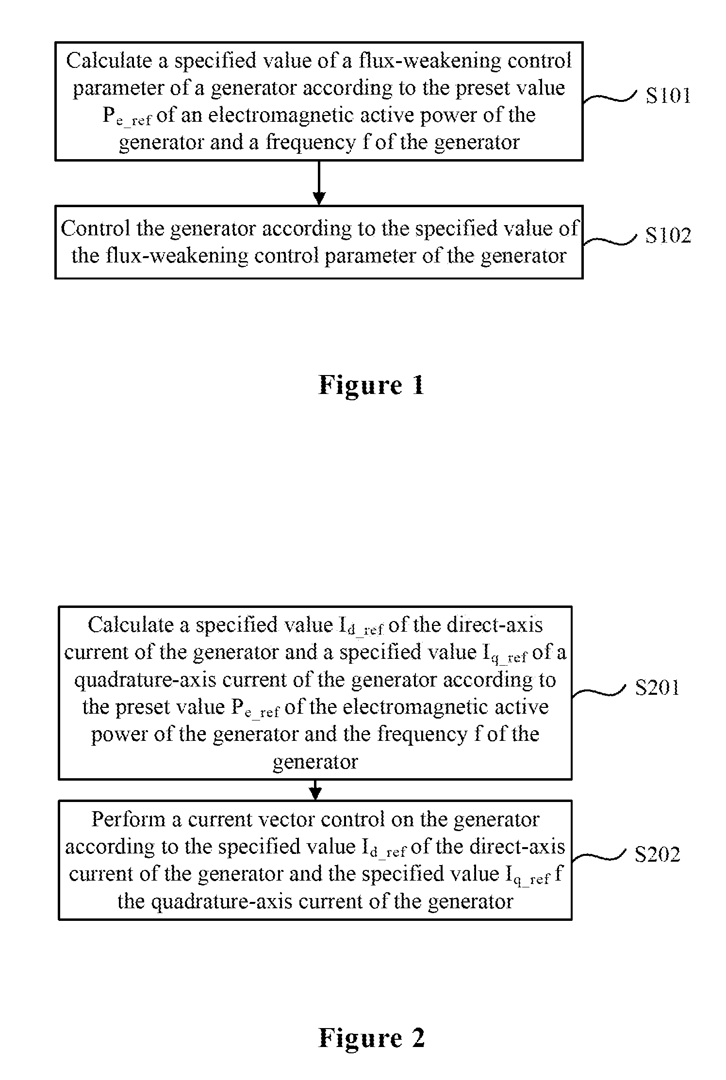
Reference is made to FIG. 1, which is a flow chart of a vibration suppression method of a wind power generator according to an embodiment of the present disclosure. As shown in FIG. 1, the method may include the following steps S101 to S102.
In step S101, a specified value of a flux-weakening control parameter of a generator is calculated according to a preset value P.sub.e.sub._.sub.ref of an electromagnetic active power of the generator and a frequency f of the generator.
In step S102, the generator is controlled according to the specified value of the flux-weakening control parameter of the generator.
Specifically, the flux-weakening control parameter of the generator in the embodiment may be determined by a control mode of the generator. For example, when a current vector control is performed on the generator, the flux-weakening control parameters of the generator in the embodiment includes a specified value I.sub.d.sub._.sub.ref of a direct-axis current of the generator and a specified value I.sub.q.sub._.sub.ref of a quadrature-axis current of the generator. When a direct torque control is performed on the generator, the flux-weakening control parameter of the generator in the embodiment includes a set value .psi..sub.f.sub._.sub.ref of a flux linkage of the generator and a set value T.sub.e.sub._.sub.ref of an electromagnetic torque of the generator.
According to the vibration suppression method and device of the wind power generator provided by the present disclosure, a specified value of a flux-weakening control parameter of the generator is calculated according to a preset value of an electromagnetic active power and a frequency of the generator. Then, the generator is controlled according to the specified value of the flux-weakening control parameter of the generator. A magnetic load of the generator is decreased by flux-weakening control. That is, electromagnetic forces on the stator and the rotor of the generator are decreased and vibration amplitudes of the stator and the rotor of the generator are reduced, to realize vibration and noise suppression. Since there is no need to change a mechanical structure and electromagnetic design of the generator, performances of the generator such as power density and force-energy index are not influenced, and the complexity of manufacturing process and the cost of the generator are not increased.
Second Embodiment
Reference is made to FIG. 2, which illustrates a flow chart of a vibration suppression method of a wind power generator according to another embodiment of the present disclosure. As shown in FIG. 2, the vibration suppression method of the wind power generator according to this embodiment provides a specific implementation (in the case of performing current vector control on the generator) of the vibration suppression method of the wind power generator shown in FIG. 1. The wind power generator vibration method in this embodiment includes the following steps S201 to S202.
In step S201, a specified value I.sub.d.sub._.sub.ref of a direct-axis current of the generator and a specified value I.sub.q.sub._.sub.ref of a quadrature-axis current of the generator are calculated according to a preset value P.sub.e.sub._.sub.ref of an electromagnetic active power of the generator and a frequency f of the generator.
Reference is made to FIG. 3, which illustrates a flow chart of a step of calculating a specified value of a flux-weakening control parameter of the generator illustrated in the embodiment shown in FIG. 2. The step may include the following steps S2011 to S2015 as shown in FIG. 3.
In step S2011, an optimal maximum output torque value I.sub.q.sub._.sub.MTPA of the quadrature-axis current of the generator and an optimal maximum output torque value I.sub.d.sub._.sub.MTPA of the direct-axis current of the generator are obtained according to a preset value P.sub.e.sub._.sub.ref of the electromagnetic active power of the generator.
This step is based on maximum torque per ampere (MTPA) control (also known as optimal torque control). An optimal combination of a direct-axis current component and a quadrature-axis current component of the generator is obtained according to electromagnetic characteristics of the generator, to make the optimal combination meet a maximum generator output torque per ampere. In a case of a given output torque of the generator, the direct-axis current component (i.e. an optimal maximum output torque value I.sub.d.sub._.sub.MTPA of the direct-axis current of the generator) and a quadrature-axis current component (i.e. an optimal maximum output torque value I.sub.q.sub._.sub.MTPA of the quadrature-axis current of the generator) of the generator are optimally allocated according to the preset value P.sub.e.sub._.sub.ref of the electromagnetic active power of the generator, so as to optimize performances of the generator, improve the operating efficiency, reduce copper loss of the generator and lower the capacity requirement of the generator. The MTPA control in this step may be achieved by applying the existing various kinds of MTPA control methods, such as the analytical method or the finite element analysis method, which will not be described herein. In addition, the MTPA control in this step may be achieved by experimental test in advance and the look-up table method.
In step S2012, a first flux-weakening specified value I.sub.d.sub._.sub.FW 1.sub._.sub.ref of the direct-axis current of the generator is obtained according to the optimal maximum output torque value I.sub.q.sub._.sub.MTPA of the quadrature-axis current and the frequency f of the generator.
In this step, the electromagnetic force of the generator are reduced according to the maximum flux-weakening capability of a converter, to suppress the vibration and the noise of the generator, which is an important step of the method for suppressing the vibration and the noise of the generator through flux-weakening control. The optimal maximum output torque value I.sub.q.sub._.sub.MTPA of the quadrature-axis current of the generator is obtained in the foregoing step S2011, and the frequency f of the generator may be calculated by the following formula:
##EQU00001## where n denotes a rotate speed of the generator which may be obtained through measurement, and p.sub.n denotes the number of pole pairs of the generator.
When the frequency f of the generator is beyond a frequency range of requiring the vibration and noise suppression, the first flux-weakening specified value I.sub.d.sub._.sub.FW 1.sub._.sub.ref of the direct-axis current of the generator is zero. When the frequency f of the generator is within the frequency range of requiring vibration and noise suppression, the first flux-weakening specified value I.sub.d.sub._.sub.FW 1.sub._.sub.ref of the direct-axis current of the generator is calculated by the following formula: I.sub.d.sub._.sub.FW 1.sub._.sub.ref= {square root over (I.sup.2.sub.a.sub._.sub.rated.sub._.sub.max-I.sup.2.sub.q.sub._.sub.MTPA- )} where I.sub.a.sub._.sub.rated.sub._.sub.max denotes a maximum value of a rated phase current of the generator, which is determined by a rated heat value of the generator.
The frequency range of requiring vibration and noise suppression may be determined by the following procedures: analyzing a vibration mode order and a frequency of a stator and rotor mechanical structural modal of the generator, and a force wave order and a frequency of electromagnetic force of the generator; determining an overlapping region between the vibration mode order and the force wave order and an overlapping region between the frequency of the stator and rotor mechanical structural modal and the frequency of electromagnetic force; determining a frequency of requiring vibration and noise suppression of the generator through test; and setting a frequency range of plus or minus 5% of the determined frequency as the frequency range of requiring vibration and noise suppression.
In step S2013, a second flux-weakening specified value I.sub.d.sub._.sub.FW 2.sub._.sub.ref of the direct-axis current of the generator is obtained according to an actual value U.sub.a.sub._.sub.active of a phase voltage of the generator and a maximum output voltage U.sub.output.sub._.sub.max of the converter.
This step is based on a flux-weakening control. When an actual value U.sub.a.sub._.sub.active of the phase voltage of the generator reaches to the maximum output voltage U.sub.output.sub._.sub.max of the converter, flux-weakening control technology is applied to make the actual value U.sub.a.sub._.sub.active of the phase voltage of the generator no longer go up. That is, the generator is controlled to operate with the actual value U.sub.a.sub._.sub.active of the phase voltage thereof being smaller than or equal to the maximum output voltage U.sub.output.sub._.sub.max of the converter. An operation mode of the generator converts from a constant-torque operation mode to a constant-power operation mode, and a range of rotate speed of the generator is enlarged. The maximum output voltage U.sub.output.sub._.sub.max of the converter may be obtained according to a direct current bus voltage U.sub.dc of the converter. A voltage difference U.sub.diff between the actual value U.sub.a.sub._.sub.active of the phase voltage of the generator and the maximum output voltage U.sub.output.sub._.sub.max of the converter is inputted to a voltage PI regulator (a proportional-integral regulator) to regulate the second flux-weakening specified value I.sub.d.sub._.sub.FW 2.sub._.sub.ref of the direct-axis current of the generator. The flux-weakening control may be achieved by the existing various kinds of flux-weakening control methods, which will not be described in detail for simplicity.
In step S2014, a specified value I.sub.d.sub._.sub.ref of the direct-axis current of the generator is obtained according to the first flux-weakening specified value I.sub.d.sub._.sub.FW 1.sub._.sub.ref of the direct-axis current of the generator, the optimal maximum output torque value I.sub.d.sub._.sub.MTPA of the direct-axis current of the generator and the second flux-weakening specified value I.sub.d.sub._.sub.FW 2.sub._.sub.ref of the direct-axis current of the generator.
The first flux-weakening specified value I.sub.d.sub._.sub.FW 1.sub._.sub.ref of the direct-axis current of the generator is obtained in the above step S2012. The optimal maximum output torque value I.sub.d.sub._.sub.MTPA of the direct-axis current of the generator is obtained in the above step S2011. The second flux-weakening specified value I.sub.d.sub._.sub.FW 2.sub._.sub.ref of the direct-axis current of the generator is obtained in the above step S2013. When the first flux-weakening specified value I.sub.d.sub._.sub.FW 1.sub._.sub.ref and the second flux-weakening specified value I.sub.d.sub._.sub.FW 2.sub._.sub.ref of the direct-axis current of the generator are both zero, the optimal maximum output torque value I.sub.d.sub._.sub.MTPA of the direct-axis current of the generator is served as the specified value I.sub.d.sub._.sub.ref of the direct-axis current of the generator, that is, I.sub.d.sub._.sub.ref=I.sub.d.sub._.sub.MTPA. When at least one of the first flux-weakening specified value I.sub.d.sub._.sub.FW 1.sub._.sub.ref and the second flux-weakening specified value I.sub.d.sub._.sub.FW 2.sub._.sub.ref of the direct-axis current of the generator is not equal to zero, the smaller one of the first flux-weakening specified value I.sub.d.sub._.sub.FW 1.sub._.sub.ref and the second flux-weakening specified value I.sub.d.sub._.sub.FW 2.sub._.sub.ref of the direct-axis current of the generator is served as the specified value I.sub.d.sub._.sub.ref of direct-axis current of the generator, that is, I.sub.d.sub._.sub.ref=Min (I.sub.d.sub._.sub.FW 1.sub._.sub.ref, I.sub.d.sub._.sub.FW 2.sub._.sub.ref).
In step S2015, a specified value I.sub.q.sub._.sub.ref of the quadrature-axis current of the generator is calculated according to the specified value I.sub.d.sub._.sub.ref of the direct-axis current of the generator and the preset value P.sub.e.sub._.sub.ref of the electromagnetic active power of the generator.
The specified value I.sub.d.sub._.sub.ref of the direct-axis current of the generator is obtained in the above step S2014 and the preset value P.sub.e.sub._.sub.ref of the electromagnetic active power of the generator is known, hence the specified value I.sub.q.sub._.sub.ref of the quadrature-axis current of the generator is calculated by the following formula: I.sub.q.sub._.sub.ref=(1.5P.sub.e.sub._.sub.ref-U.sub.dI.sub.d.sub._.sub.- ref)/U.sub.q where U.sub.d denotes a direct-axis voltage of the generator, and U.sub.q denotes a quadrature-axis voltage of the generator.
In step S202, a current vector control is performed on the generator according to the specified value I.sub.d.sub._.sub.ref of the direct-axis current of the generator and the specified value I.sub.q.sub._.sub.ref of the quadrature-axis current of the generator.
The specified value I.sub.d.sub._.sub.ref of the direct-axis current of the generator is obtained in the above step S2014 and the specified value I.sub.q.sub._.sub.ref of the quadrature-axis current of the generator is obtained in the above step S2015. Then, the converter performs the current vector control on the generator according to the specified value I.sub.d.sub._.sub.ref of the direct-axis current of the generator and the specified value I.sub.q.sub._.sub.ref of the quadrature-axis current of the generator. When the frequency f of the generator is within the frequency range of requiring the vibration and noise suppression, the converter operates in the flux-weakening control manner to suppress the vibration and noise of the generator.
According to the vibration suppression method and device of the wind power generator provided by the present disclosure, the specified value of the direct-axis current of the generator and the specified value of the quadrature-axis current of the generator are calculated according to the preset value of electromagnetic active power of the generator and the frequency of the generator. Then, a current vector control is performed on the generator according to the specified value of the direct-axis current of the generator and the specified value of the quadrature-axis current of the generator. Through flux-weakening control, a magnetic load of the generator is decreased, that is, the electromagnetic force on the stator and the rotor of the generator is decreased. Thus, vibration amplitude of the stator and rotor of the generator is reduced, and the vibration and noise suppression is implemented. Since there is no need to change a mechanical structure and electromagnetic design of the generator, performances of the venerator such like power density and force-energy index, are not influenced, and the complexity of manufacturing process and the cost of the generator are not increased.
Third Embodiment
Reference is made to FIG. 4, which illustrates a flow chart of a vibration suppression method of a wind power generator according to another embodiment of the present disclosure. As shown in FIG. 4, the vibration suppression method of the wind power generator in this embodiment provides another implementation (that is, the case of performing a direct torque control on the generator) of the vibration suppression method of the wind power generator shown in FIG. 1. The vibration suppression method of the wind power generator in this embodiment includes the following steps S401 to S402.
In step S401, a specified value .psi..sub.f.sub._.sub.ref of a flux linkage of the generator and a specified value T.sub.e.sub._.sub.ref of an electromagnetic torque of the generator are calculated according to a preset value P.sub.e.sub._.sub.ref of an electromagnetic active power of the generator and a frequency f of the generator.
Reference is made to FIG. 5, which illustrates a flow chart of a step of calculating a specified value of a flux-weakening control parameter of the generator in an embodiment shown in FIG. 4. The step may include the following steps S4011 to S4015 as shown in FIG. 5.
In step S4011, an optimal maximum output torque value T.sub.e.sub._.sub.MTPA of the electromagnetic torque of the generator and an optimal maximum output torque value .psi..sub.f.sub._.sub.MTPA of the flux linkage of the generator are obtained according to a preset value P.sub.e.sub._.sub.ref of the electromagnetic active power of the generator.
This step is based on MTPA control. An optimal combination of the flux linkage and the electromagnetic torque of the generator is obtained according to electromagnetic characteristics of the generator, to make a maximum generator output torque per ampere. In a case of a given output torque of the generator, the flux linkage (i.e. the optimal maximum output torque value .psi..sub.f.sub._.sub.MTPA of the flux linkage of the generator) and the electromagnetic torque (i.e. the optimal maximum output torque value T.sub.e.sub._.sub.MTPA of the electromagnetic torque of the generator) of the generator are optimally allocated according to the preset point value P.sub.e.sub._.sub.ref of the electromagnetic active power of the generator, so as to optimize performances of the generator, improve the operating efficiency, reduce copper loss of the generator and lower the capacity requirement of the generator. The MTPA control in this step may be achieved by applying the existing various kinds of MTPA control methods, such as the analytical method or the finite element analysis method which will not be described herein. In addition, the MTPA control in this step may be achieved by experimental test in advance and the look-up table method.
In step S4012, a first flux-weakening specified value .psi..sub.f.sub._.sub.FW 1.sub._.sub.ref of the flux linkage of the generator is obtained according to the optimal maximum output torque value T.sub.e.sub._.sub.MTPA of the electromagnetic torque of the generator and the frequency f of the generator.
In this step, electromagnetic force of the generator are reduced according to the maximum flux-weakening capability of a converter, to suppress the vibration and the noise of the generator, which is an important step of the method for suppressing the vibration and the noise of the generator through flux-weakening control. The optimal maximum output torque value T.sub.e.sub._.sub.MTPA of the electromagnetic torque of the generator is obtained in the foregoing step S4011, and the frequency f of the generator may be calculated by the following formula:
##EQU00002## where n denotes a rotate speed of the generator which may be obtained through measurement, and p.sub.n denotes the number of pole pairs of the generator.
When the frequency f of the generator is beyond a frequency range of requiring the vibration and noise suppression, the first flux-weakening preset value .psi..sub.f.sub._.sub.FW 1.sub._.sub.ref of the flux linkage of the generator is a preset value .psi..sub.f.sub._.sub.rated.sub._.sub.ref of a rated flux linkage. When the frequency f of the generator is within the frequency scope of requiring the vibration and noise suppression, the first flux-weakening preset value .psi..sub.f.sub._.sub.FW 1.sub._.sub.ref of the flux linkage of the generator is calculated by the following formula:
.psi..times..times..times..times..omega. ##EQU00003## .omega..times..times..pi..times..times..pi..times..times. ##EQU00003.2## where U.sub.a.sub._.sub.active denotes an actual value of a phase voltage of the generator, R.sub.a denotes a resistance of a stator winding of the generator; I.sub.a.sub._.sub.rated.sub._.sub.max denotes a maximum value of a rated phase current of the generator, which is determined by a rated heat value of the generator; .omega..sub.e denotes an electrical angular speed of the generator; p.sub.n denotes the number of pole pairs of the electrical angular velocity; and n denotes a rotate speed of the electrical angular velocity, which can be obtained through measurement.
The frequency range of requiring the vibration and noise suppression may be determined according to related descriptions in the step S2012 of the embodiment illustrated by FIG. 2, which will not be described again herein for simplicity.
In step S4013, a second flux-weakening specified value .psi..sub.f.sub._.sub.FW 2.sub._.sub.ref of the flux linkage of the generator is obtained according to an actual value U.sub.a.sub._.sub.active of a phase voltage of the generator and a maximum output voltage U.sub.output.sub._.sub.max of a converter.
This step is based on the flux-weakening control. When an actual value U.sub.a.sub._.sub.active of the phase voltage of the generator reaches to the maximum output voltage U.sub.output.sub._.sub.max of the converter, flux-weakening control technology is applied to make the actual value U.sub.a.sub._.sub.active of the phase voltage of the generator no longer go up. That is, the generator is controlled to operate with the actual value U.sub.a.sub._.sub.active of the phase voltage thereof being smaller than or equal to the maximum output voltage U.sub.output.sub._.sub.max of the converter. An operation mode of the generator converts from a constant-torque operation mode to a constant-power operation mode, and the range of rotate speed of the generator is enlarged. The maximum output voltage U.sub.output.sub._.sub.max of the converter may be obtained according to a direct current bus voltage U.sub.dc of the converter. A voltage difference U.sub.diff between the actual value U.sub.a.sub._.sub.active of the phase voltage of the generator and the maximum output voltage U.sub.output.sub._.sub.max of the converter is inputted to a voltage PI regulator to regulate the second flux-weakening specified value .psi..sub.f.sub._.sub.FW 2.sub._.sub.ref of the flux linkage of the generator. The flux-weakening control may be achieved by the existing various kinds of flux-weakening control methods, which will not be described in detail herein for simplicity.
In step S4014, the specified value .psi..sub.f.sub._.sub.ref of the flux linkage of the generator is obtained according to the first flux-weakening specified value .psi..sub.f.sub._.sub.FW 1.sub._.sub.ref of the flux linkage of the generator, the optimal maximum output torque value .psi..sub.f.sub._.sub.MTPA of the flux linkage of the generator and a second flux-weakening specified value .psi..sub.f.sub._.sub.FW 2.sub._.sub.ref of the flux linkage of the generator.
The first flux-weakening specified value .psi..sub.f.sub._.sub.FW 1.sub._.sub.ref of the flux linkage of the generator is obtained in the above step S4012. The optimal maximum output torque value .psi..sub.f.sub._.sub.MTPA of the flux linkage of the generator is obtained in the above step S4011. The second flux-weakening specified value .psi..sub.f.sub._.sub.FW 2.sub._.sub.ref of the flux linkage of the generator is obtained in the above step S4013. When the first flux-weakening specified value .psi..sub.f.sub._.sub.FW 1.sub._.sub.ref and the second flux-weakening specified value .psi..sub.f.sub._.sub.FW 2.sub._.sub.ref of the flux linkage of the generator are both equal to the preset value .psi..sub.f.sub._.sub.rated.sub._.sub.ref of the rated flux linkage, the optimal maximum output torque value .psi..sub.f.sub._.sub.MTPA of the flux linkage of the generator is served as a specified value .psi..sub.f.sub._.sub.ref of the flux linkage of the generator, that is, .psi..sub.f.sub._.sub.ref=.psi..sub.f.sub._.sub.MTPA. When at least one of the first flux-weakening specified value .psi..sub.f.sub._.sub.FW 1.sub._.sub.ref and the second flux-weakening specified value .psi..sub.f.sub._.sub.FW 2.sub._.sub.ref of the flux linkage of the generator is not equal to the preset value .psi..sub.f.sub._.sub.rated.sub._.sub.ref of the rated flux linkage, the smaller one from the first flux-weakening specified value .psi..sub.f.sub._.sub.FW 1.sub._.sub.ref and the second flux-weakening specified value .psi..sub.f.sub._.sub.FW 2.sub._.sub.ref of the flux linkage of the generator is served as a specified value .psi..sub.f.sub._.sub.ref of the flux linkage of the generator, that is, .psi..sub.f.sub._.sub.ref=Min (.psi..sub.f.sub._.sub.FW 1.sub._.sub.ref, .psi..sub.f.sub._.sub.FW 2.sub._.sub.ref).
In step S4015, the specified value T.sub.f.sub._.sub.ref of the electromagnetic torque of the generator is calculated according to the specified value .psi..sub.f.sub._.sub.ref of the flux linkage of the generator.
The specified value .psi..sub.f.sub._.sub.ref of the flux linkage of the generator is obtained in the above step S4014, hence the specified value T.sub.f.sub.--ref of the electromagnetic torque of the generator is calculated by the following formula: T.sub.e.sub._.sub.ref=1.5P.sub.n(.psi..sub.f.sub._.sub..alpha..sub._.sub.- refI.sub..beta.-.psi..sub.f.sub._.sub..beta..sub._.sub.refI.sub..alpha.) where p.sub.n denotes the number of generator pole pairs, .psi..sub.f.sub.--ref denotes .alpha. axis component of the specified value .psi..sub.f.sub.--ref of the flux linkage of the generator, .psi..sub.f.sub.--ref denotes a .beta. axis component of the specified value .psi..sub.f.sub.--ref of the flux linkage of the generator, I.sub..alpha. denotes .alpha. axis current of the generator, and I.sub..beta.denotes a .beta. axis current of the generator.
In step S402, a direct torque control is performed on the generator according to the specified value .psi..sub.f.sub._.sub.ref of the flux linkage of the generator and the specified value T.sub.e.sub._.sub.ref of the electromagnetic torque of the generator.
The specified value .psi..sub.f.sub._.sub.ref of the flux linkage of the generator is obtained in the above step S4014 and the specified value T.sub.e.sub._.sub.ref of the electromagnetic torque of the generator is obtained in the above step S4015. Thus, the converter performs the direct torque control on the generator according to the specified value .psi..sub.f.sub._.sub.ref of the flux linkage of the generator and the specified value T.sub.e.sub._.sub.ref of the electromagnetic torque of the generator.
According to the vibration suppression method and device of the wind power generator provided by the present disclosure, the specified value of the flux linkage of the generator and the specified value of the electromagnetic torque of the generator are calculated according to a preset value of the electromagnetic active power of the generator and the frequency of the generator. Then, a direct torque control is performed on the generator according to the specified value of the flux linkage of the generator and the specified value of the electromagnetic torque of the generator. Through flux-weakening control, a magnetic load of the generator is decreased, that is, the electromagnetic force on the stator and the rotor of the generator is decreased, vibration amplitude of the stator and the rotor of the generator are reduced, and the vibration and noise suppression is implemented. Since there is no need to change a mechanical structure and electromagnetic design of the generator, performances of the generator such like power density and force-energy index are not influenced, and the complexity of manufacturing processes and the cost of the generator are not increased.
Fourth Embodiment
Reference is made to FIG. 6, which illustrates a schematic structural diagram of a vibration suppression device of a wind power generator according to an embodiment of the present disclosure. As shown in FIG. 6, the vibration suppression device of the wind power generator in this embodiment can implement the vibration suppression method of the wind power generator in the embodiment shown in FIG. 1. Specifically, the vibration suppression device of the wind power generator in this embodiment may include: a calculation module 61 and a control module 62. The calculation module 61 is configured to calculate a specified value of a flux-weakening control parameter of a generator according to a preset value P.sub.e.sub._.sub.ref of an electromagnetic active power of the generator and a frequency f of the generator. The control module 62 is configured to control the generator according to the specified value of the flux-weakening control parameter of the generator.
The detailed procedures for achieving the functions of each module in this embodiment can be found in related descriptions in the embodiment shown in FIG. 1, which will not be described again herein for simplicity.
According to the wind power generator vibration suppression method and device provided by the present disclosure, the specified value of the flux-weakening control parameter of the generator is calculated according to the preset value of the electromagnetic active power of the generator and the frequency of the generator. Then, the generator is controlled according to the specified value of the flux-weakening control parameter of the generator. A magnetic load of the generator is decreased by flux-weakening control. That is, electromagnetic forces on the stator and the rotor of the generator are decreased, vibration amplitudes of the stator and the rotor of the generator are reduced, and the vibration and noise suppression is implemented. Since there is no need to change a mechanical structure and electromagnetic design of the generator, performances of the generator such like power density and force-energy index are not influenced, and the complexity of manufacturing process and the cost of the generator are not increased.
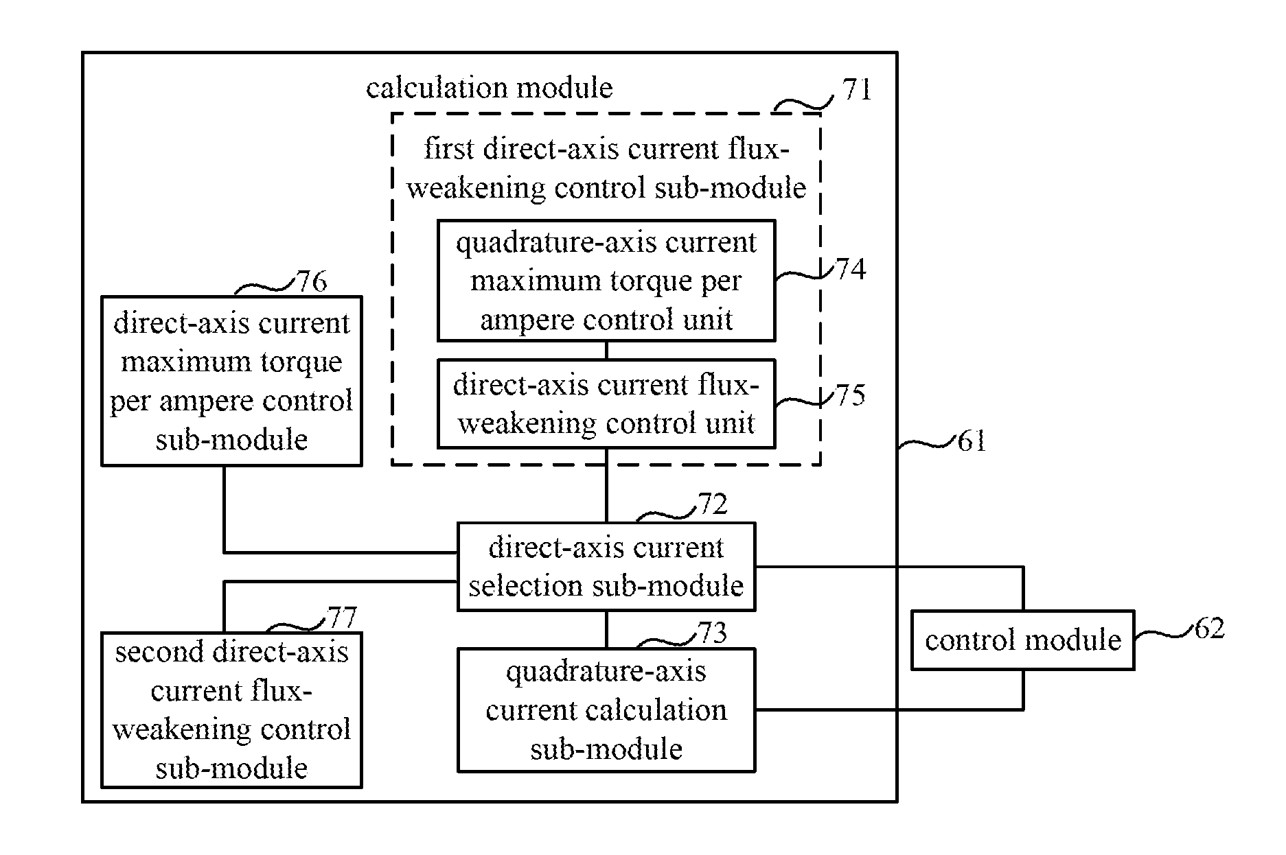
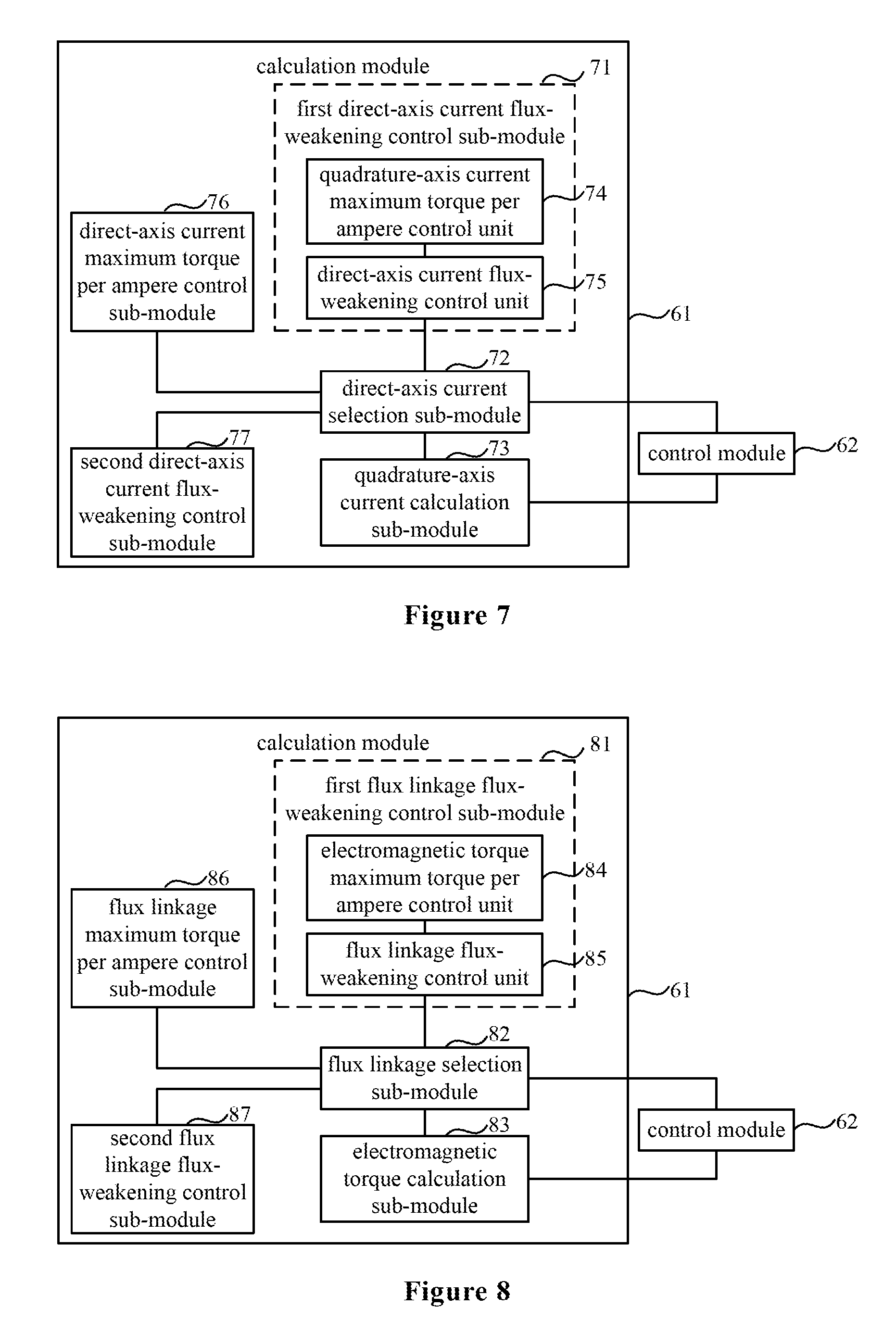
Fifth Embodiment
Reference is made to FIG. 7, which illustrates a schematic structural diagram of a vibration suppression device of a wind power generator according to another embodiment of the present disclosure. FIG. 7 shows a specific structure of the vibration suppression device of the wind power generator in the embodiment shown in FIG. 6 (in a case of performing a current vector control on the generator), and the device can implement the vibration suppression method of the wind power generator in the embodiment shown in FIG. 2. Specifically, the calculation module 61 in the embodiment shown in FIG. 6 is configured to obtain a specified value I.sub.d.sub._.sub.ref of a direct-axis current of the generator and a specified value I.sub.q.sub._.sub.ref of a quadrature-axis current of the generator according to a preset value P.sub.e.sub._.sub.ref of an electromagnetic active power of the generator and a frequency f of the generator.
The control module 62 in the embodiment shown in FIG. 6 is configured to perform a current vector control on the generator according to the specified value I.sub.d.sub._.sub.ref of the direct-axis current of the generator and the specified value I.sub.q.sub._.sub.ref of the quadrature-axis current of the generator.
Further, the calculation module 61 may include: a first direct-axis current flux-weakening control sub-module 71 configured to obtain a first flux-weakening specified value I.sub.d.sub._.sub.FW 1.sub._.sub.ref of a direct-axis current of the generator according to a preset value P.sub.e.sub._.sub.ref of an electromagnetic active power of the generator and a frequency f of the generator; a direct-axis current selection sub-module 72 configured to obtain a specified value I.sub.d.sub._.sub.ref of the direct-axis current of the generator according to a first flux-weakening specified value I.sub.d.sub._.sub.FW 1.sub._.sub.ref of the direct-axis current of the generator, an optimal maximum output torque value I.sub.d.sub._.sub.MTPA of the direct-axis current of the generator and a second flux-weakening specified value I.sub.d.sub._.sub.FW 2.sub._.sub.ref of the direct-axis current of the generator; and a quadrature-axis current calculation sub-module 73 configured to calculate a specified value I.sub.q.sub._.sub.ref of a quadrature-axis current of the generator according to the specified value I.sub.d.sub._.sub.ref of the direct-axis current of the generator and the preset value P.sub.e.sub._.sub.ref of the electromagnetic active power of the generator.
Further, the first direct-axis current flux-weakening control sub-module 71 further include: a quadrature-axis current maximum torque per ampere control unit 74 configured to obtain an optimal maximum output torque value I.sub.q.sub._.sub.MTPA of a quadrature-axis current of the generator according to the preset value P.sub.e.sub._.sub.ref of the electromagnetic active power of the generator; and a direct-axis current flux-weakening control unit 75 configured to obtain a first flux-weakening specified value I.sub.d.sub._.sub.FW 1.sub._.sub.ref of the direct-axis current of the generator according to the optimal maximum output torque value I.sub.q.sub._.sub.MTPA of the quadrature-axis current of the generator and the frequency f of the generator.
Further, the calculation module 61 may further include: a direct-axis current maximum torque per ampere control sub-module 76 configured to obtain an optimal maximum output torque value I.sub.d.sub._.sub.MTPA of the direct-axis current of the generator according to the preset value P.sub.e.sub._.sub.ref of the electromagnetic active power of the generator; and a second direct-axis current flux-weakening control sub-module 77 configured to obtain a second flux-weakening specified value I.sub.d.sub._.sub.FW 2.sub._.sub.ref of the direct-axis current of the generator according to an actual value U.sub.a.sub._.sub.active of a phase voltage of the generator and a maximum output voltage U.sub.output.sub._.sub.max of a converter.
The specific procedures for achieving functions of all modules, sub-modules and units can be found in related descriptions in the embodiment shown in FIG. 2, which will not be described again herein for simplicity.
It should be noted that, the functions of the quadrature-axis current maximum torque per ampere control unit 74 and the direct-axis current maximum torque per ampere control sub-module 76 may be achieved by one module in practice.
According to the vibration suppression method and device of the wind power generator provided by the present disclosure, the specified value of the direct-axis current of the generator and the specified value of the quadrature-axis current of the generator are calculated according to the preset value of the electromagnetic active power of the generator and the frequency of the generator. A current vector control is performed on the generator according to the specified value of the direct-axis current of the generator and the specified value of the quadrature-axis current of the generator. A magnetic load of the generator is decreased by flux-weakening control. Thus, electromagnetic forces on the stator and the rotor of the generator are decreased and vibration amplitudes of the stator and the rotor of the generator are reduced, to realize vibration and noise suppression. Since there is no need to change a mechanical structure and electromagnetic design of the generator, performances of the generator such like power density and force-energy index are not influenced, and the complexity of manufacturing processes and the cost of the generator are not increased.
Sixth Embodiment
Reference is made to FIG. 8, which illustrates a schematic structural diagram of a vibration suppression device of a wind power generator according to another embodiment of the present disclosure. FIG. 8 shows a specific structure of the vibration suppression device of the wind power generator in the embodiment shown in FIG. 6 (in a case of performing a direct torque control on the generator), and the device can implement the vibration suppression method of the wind power generator in the embodiment shown in FIG. 4.
Specifically, the calculation module 61 in the embodiment shown in FIG. 6 is further configured to obtain a specified value .psi..sub.f.sub._.sub.ref of a flux linkage of the generator and a specified value T.sub.e.sub._.sub.ref of an electromagnetic torque of the generator according to a preset value P.sub.e.sub._.sub.ref of an electromagnetic active power of the generator and a frequency f of the generator.
The control module 62 in the embodiment shown in FIG. 6 is further configured to perform a direct torque control on the generator according to the specified value .psi..sub.f.sub._.sub.ref of the flux linkage of the generator and the specified value T.sub.e.sub._.sub.ref of the electromagnetic torque of the generator.
Further, the calculation module 61 may include: a first flux linkage flux-weakening control sub-module 81 configured to obtain a first flux-weakening specified value .psi..sub.f.sub._.sub.FW 1.sub._.sub.ref of the flux linkage of the generator according to the preset value P.sub.e.sub._.sub.ref of the electromagnetic active power of the generator and the frequency f of the generator; a flux linkage selection sub-module 82, configured to obtain the specified value .psi..sub.f.sub._.sub.ref of the flux linkage of the generator according to a first flux-weakening specified value .psi..sub.f.sub._.sub.FW 1.sub._.sub.ref of the flux linkage of the generator, the optimal maximum output torque value .psi..sub.f.sub._.sub.MTPA of the flux linkage of the generator and a second flux-weakening specified value .psi..sub.d.sub._.sub.FW 2.sub._.sub.ref of the flux linkage of the generator; and an electromagnetic torque calculation sub-module 83 configured to calculate the specified value T.sub.e.sub._.sub.ref of the electromagnetic torque of the generator according to the specified value .psi..sub.f.sub._.sub.ref of the flux linkage of the generator.
Further, the first flux linkage flux-weakening control sub-module 81 may further include: an electromagnetic torque maximum torque per ampere control unit 84 configured to obtain an optimal maximum output torque value T.sub.e.sub._.sub.MTPA of the electromagnetic torque of the generator according to the preset value P.sub.e.sub._.sub.ref of the electromagnetic active power of the generator; and a flux linkage flux-weakening control unit 85 configured to obtain a first flux-weakening specified value .psi..sub.f.sub._.sub.FW 1.sub._.sub.ref of the flux linkage of the generator according to the optimal maximum output torque value T.sub.e.sub._.sub.MTPA of the electromagnetic torque of the generator and the frequency f of the generator.
Further, the calculation module 61 may further include: a flux linkage maximum torque per ampere control sub-module 86 configured to obtain the optimal maximum output torque value .psi..sub.f.sub._.sub.ref of the flux linkage of the generator according to the preset value P.sub.e.sub._.sub.ref of the electromagnetic active power of the generator; and a second flux linkage flux-weakening control sub-nodule 87 configured to obtain the second flux-weakening specified value .psi..sub.d.sub._.sub.FW 2.sub._.sub.ref of the flux linkage of the generator according to an actual value U.sub.a.sub._.sub.active of a generator phase voltage of the generator and a maximum output voltage U.sub.output.sub._.sub.max of a converter.
The specific procedures for achieving functions of all modules, sub-modules and units can be found in related descriptions in the embodiment shown in FIG. 4, which will not be described again herein for simplicity.
It should be noted that, the functions of the electromagnetic torque maximum torque per ampere control unit 84 and the flux linkage maximum torque per ampere control sub-module 86 may be achieved by one module in practice.
According to the vibration suppression method and device of the wind power generator provided by the present disclosure, the specified value of the flux linkage of the generator and the specified value of the electromagnetic torque of the generator are calculated according to the preset value of the electromagnetic active power of the generator and the frequency of the generator. A direct torque control is performed on the generator according to the specified value of the flux linkage of the generator and the specified value of the electromagnetic torque of the generator. A magnetic load of the generator is decreased by flux-weakening control. That is, electromagnetic forces on the stator and the rotor of the A magnetic load of the generator is decreased are decreased and vibration amplitudes of the stator and the rotor of the generator are reduced, and realize vibration and noise suppression is implemented. Since there is no need to change a mechanical structure and electromagnetic design of the generator, performances of the generator such like power density and force-energy index are not influenced, and the complexity of manufacturing process and the cost of the generator are not increased
It should be noted that, the vibration suppression method and device of the wind power generator provided in the present disclosure can also be applied to other generators or motors.
The foregoing is merely embodiments of the present disclosure and is not intended to limit the scope of the present disclosure. Any modifications, equivalent substitutions, improvements, and the like within the technical scope disclosed by the present disclosure are intended to be included within the scope of the present disclosure.
* * * * *
D00000
D00001
D00002
D00003
D00004
M00001
M00002
M00003
XML
uspto.report is an independent third-party trademark research tool that is not affiliated, endorsed, or sponsored by the United States Patent and Trademark Office (USPTO) or any other governmental organization. The information provided by uspto.report is based on publicly available data at the time of writing and is intended for informational purposes only.
While we strive to provide accurate and up-to-date information, we do not guarantee the accuracy, completeness, reliability, or suitability of the information displayed on this site. The use of this site is at your own risk. Any reliance you place on such information is therefore strictly at your own risk.
All official trademark data, including owner information, should be verified by visiting the official USPTO website at www.uspto.gov. This site is not intended to replace professional legal advice and should not be used as a substitute for consulting with a legal professional who is knowledgeable about trademark law.