Convection oven
McKee , et al.
U.S. patent number 10,337,745 [Application Number 15/094,645] was granted by the patent office on 2019-07-02 for convection oven. This patent grant is currently assigned to Alto-Shaam, Inc.. The grantee listed for this patent is ALTO-SHAAM, INC.. Invention is credited to Philip R. McKee, Lee Thomas VanLanen.
View All Diagrams
| United States Patent | 10,337,745 |
| McKee , et al. | July 2, 2019 |
Convection oven
Abstract
A convection oven having one or more intermediate air plenums is disclosed. An intermediate air plenum placed within an oven cavity defines the bottom of an upper cooking chamber and the top of a lower cooking chamber. Each intermediate air plenum comprises a left side air inlet for receiving heated air from a left side air channel located on a left side cavity wall of the oven cavity, a right side air inlet for receiving heated air from a right side air channel located on a right side cavity wall of the oven cavity, a top plenum surface including a plurality of top air outlets configured to direct a portion of the heated air upwards, and a bottom plenum surface including a plurality of bottom air outlets configured to direct a portion of the heated air downwards. The top and bottom plenum surfaces are preferably shaped to optimize even distribution of heated air flow into the oven cavity.
| Inventors: | McKee; Philip R. (Frisco, TX), VanLanen; Lee Thomas (McKinney, TX) | ||||||||||
|---|---|---|---|---|---|---|---|---|---|---|---|
| Applicant: |
|
||||||||||
| Assignee: | Alto-Shaam, Inc. (Menomonee
Falls, WI) |
||||||||||
| Family ID: | 57450930 | ||||||||||
| Appl. No.: | 15/094,645 | ||||||||||
| Filed: | April 8, 2016 |
Prior Publication Data
| Document Identifier | Publication Date | |
|---|---|---|
| US 20160356506 A1 | Dec 8, 2016 | |
Related U.S. Patent Documents
| Application Number | Filing Date | Patent Number | Issue Date | ||
|---|---|---|---|---|---|
| 15016093 | Feb 4, 2016 | 9879865 | |||
| 14733533 | Jun 8, 2015 | 9677774 | |||
| Current U.S. Class: | 1/1 |
| Current CPC Class: | F24C 15/18 (20130101); F24C 15/322 (20130101); F24C 15/16 (20130101); A21B 1/245 (20130101) |
| Current International Class: | F24C 15/32 (20060101); A21B 1/24 (20060101); F24C 15/16 (20060101); F24C 15/18 (20060101) |
| Field of Search: | ;126/21A,21R,15R,15A |
References Cited [Referenced By]
U.S. Patent Documents
| 1527020 | February 1925 | Valliant |
| 2098295 | November 1937 | Kettering et al. |
| 2214630 | September 1940 | Wheeler |
| 2305056 | December 1942 | Austin |
| 2491687 | December 1949 | Nutt |
| 2513846 | July 1950 | Collins |
| 2593077 | April 1952 | Vogt |
| 2683795 | July 1954 | Sheidler |
| 2715898 | August 1955 | Michaelis et al. |
| 2940381 | August 1960 | Cottongim et al. |
| 3221729 | December 1965 | Beasley et al. |
| 3232072 | February 1966 | Barroero |
| 3304406 | February 1967 | King |
| 3326201 | June 1967 | Murray |
| 3335499 | August 1967 | Larsson |
| 3514576 | May 1970 | Hilton et al. |
| 3538904 | November 1970 | Baker |
| 3568590 | March 1971 | Grice |
| 3658047 | April 1972 | Happel |
| 3674982 | July 1972 | Hoyt |
| 3712285 | January 1973 | Copeland |
| 3789516 | February 1974 | Schraft et al. |
| 3828760 | August 1974 | Farber et al. |
| 3884213 | May 1975 | Smith |
| 3908533 | September 1975 | Fagerstrom et al. |
| 3935809 | February 1976 | Bauer |
| 3946651 | March 1976 | Garcia |
| 4038968 | August 1977 | Rovell |
| 4110916 | September 1978 | Bemrose |
| 4154881 | May 1979 | Smith |
| 4162141 | July 1979 | West |
| 4189995 | February 1980 | Lohr et al. |
| 4307286 | December 1981 | Guibert |
| 4307659 | December 1981 | Martin et al. |
| 4313485 | February 1982 | Gidge et al. |
| 4323110 | April 1982 | Rubbright et al. |
| 4326342 | April 1982 | Schregenberger |
| 4338911 | July 1982 | Smith |
| 4354549 | October 1982 | Smith |
| 4366177 | December 1982 | Wells et al. |
| 4374319 | February 1983 | Guibert |
| 4377109 | March 1983 | Brown et al. |
| 4381442 | April 1983 | Guibert |
| 4389562 | June 1983 | Chaudoir |
| 4395233 | July 1983 | Smith |
| 4397299 | August 1983 | Taylor et al. |
| 4404898 | September 1983 | Chaudoir |
| 4455478 | June 1984 | Guibert |
| 4462383 | July 1984 | Henke et al. |
| 4471750 | September 1984 | Burtea |
| 4472887 | September 1984 | Avedian et al. |
| 4474498 | October 1984 | Smith |
| 4479776 | October 1984 | Smith |
| 4484561 | November 1984 | Baggott et al. |
| 4492839 | January 1985 | Smith |
| 4515143 | May 1985 | Jabas |
| 4516012 | May 1985 | Smith et al. |
| 4601237 | July 1986 | Harter et al. |
| 4605038 | August 1986 | Tchitdjian |
| 4625867 | December 1986 | Guibert |
| 4626661 | December 1986 | Henke |
| 4631029 | December 1986 | Lanham et al. |
| 4690127 | September 1987 | Sank |
| 4700619 | October 1987 | Scanlon |
| 4714050 | December 1987 | Nichols |
| 4722683 | February 1988 | Royer |
| 4727863 | March 1988 | Stephan et al. |
| 4739154 | April 1988 | Bharara et al. |
| 4750276 | June 1988 | Smith et al. |
| 4757800 | July 1988 | Shei et al. |
| 4822981 | April 1989 | Chaudoir |
| 4829158 | May 1989 | Burnham |
| 4829982 | May 1989 | Abidor |
| 4835351 | May 1989 | Smith et al. |
| 4865864 | September 1989 | Rijswijck |
| 4867132 | September 1989 | Yencha |
| 4870254 | September 1989 | Arabori |
| 4876426 | October 1989 | Smith |
| 4892030 | January 1990 | Grieve |
| 4895137 | January 1990 | Jones et al. |
| 4928663 | May 1990 | Nevin et al. |
| 4951645 | August 1990 | Luebke et al. |
| 4960977 | October 1990 | Alden |
| 4965435 | October 1990 | Smith et al. |
| 4981416 | January 1991 | Nevin et al. |
| 4994181 | February 1991 | Mullaney, Jr. |
| 5025775 | June 1991 | Crisp |
| 5050578 | September 1991 | Luebke et al. |
| 5121737 | June 1992 | Yencha, III |
| 5172682 | December 1992 | Luebke et al. |
| 5180898 | January 1993 | Alden et al. |
| 5211106 | May 1993 | Lucke |
| 5218950 | June 1993 | Hait |
| 5222474 | June 1993 | Yencha, III |
| 5223290 | June 1993 | Alden |
| 5228385 | July 1993 | Friedrich et al. |
| 5231920 | August 1993 | Alden et al. |
| 5254823 | October 1993 | McKee et al. |
| 5272317 | December 1993 | Ryu |
| 5309981 | May 1994 | Birder |
| 5345923 | September 1994 | Luebke et al. |
| 5361749 | November 1994 | Smith et al. |
| 5365039 | November 1994 | Chaudoir |
| 5404935 | April 1995 | Liebermann |
| 5421316 | June 1995 | Heber |
| 5421317 | June 1995 | Cole et al. |
| 5434390 | July 1995 | McKee et al. |
| 5454295 | October 1995 | Cox et al. |
| 5458051 | October 1995 | Alden et al. |
| 5460157 | October 1995 | Prabhu |
| 5483044 | January 1996 | Thorneywork et al. |
| 5492055 | February 1996 | Nevin et al. |
| 5497760 | March 1996 | Alden et al. |
| 5507382 | April 1996 | Hartwell et al. |
| 5520095 | May 1996 | Huber et al. |
| 5530223 | June 1996 | Culzoni et al. |
| 5558793 | September 1996 | McKee et al. |
| 5572984 | November 1996 | Alden et al. |
| 5577438 | November 1996 | Amitrano et al. |
| 5582093 | December 1996 | Amitrano et al. |
| 5620731 | April 1997 | McKee |
| 5647740 | July 1997 | Kobaru |
| 5655511 | August 1997 | Prahhu et al. |
| 5676044 | October 1997 | Lara, Jr. |
| 5683240 | November 1997 | Smith et al. |
| 5720273 | February 1998 | Trullas |
| 5747775 | May 1998 | Tsukamoto et al. |
| 5847365 | December 1998 | Harter et al. |
| 5880436 | March 1999 | Keogh |
| 5908574 | June 1999 | Keogh |
| 5927265 | July 1999 | McKee et al. |
| 5928072 | July 1999 | Fulcher et al. |
| 5928541 | July 1999 | Tsukamoto et al. |
| 5934178 | August 1999 | Caridis et al. |
| 5934182 | August 1999 | Harter et al. |
| 5941235 | August 1999 | Carter |
| 5951901 | September 1999 | Douglas et al. |
| 5954986 | September 1999 | Tsukerhote et al. |
| 5988154 | November 1999 | Douglas et al. |
| 5990466 | November 1999 | McKee et al. |
| 5994673 | November 1999 | El-Shoubary |
| 6008483 | December 1999 | McKee et al. |
| 6031208 | February 2000 | Witt et al. |
| 6049066 | April 2000 | Wilson |
| 6058924 | May 2000 | Pool, III et al. |
| 6060701 | May 2000 | McKee et al. |
| 6064050 | May 2000 | Ishikawa et al. |
| 6079321 | June 2000 | Harter et al. |
| 6111224 | August 2000 | Witt |
| 6116895 | September 2000 | Onuschak |
| 6140619 | October 2000 | Couch |
| 6140626 | October 2000 | McKee et al. |
| 6146678 | November 2000 | Caridis et al. |
| 6175099 | January 2001 | Shei et al. |
| 6192877 | February 2001 | Moshonas et al. |
| 6218650 | April 2001 | Tsukamoto et al. |
| 6252201 | June 2001 | Nevarez |
| 6259064 | July 2001 | Wilson |
| 6262394 | July 2001 | Shei et al. |
| 6262396 | July 2001 | Witt et al. |
| 6262406 | July 2001 | McKee et al. |
| 6320165 | November 2001 | Ovadia |
| 6323462 | November 2001 | Strand |
| 6350965 | February 2002 | Fukushima et al. |
| 6359271 | March 2002 | Gidner et al. |
| 6376817 | April 2002 | McFadden |
| 6378602 | April 2002 | Brown |
| 6384381 | May 2002 | Witt et al. |
| 6399930 | June 2002 | Day et al. |
| 6403937 | June 2002 | Day et al. |
| 6425388 | July 2002 | Korinchock |
| 6441355 | August 2002 | Thorneywork |
| 6455085 | September 2002 | Duta |
| 6476368 | November 2002 | Aronsson et al. |
| 6486455 | November 2002 | Merabet |
| 6494130 | December 2002 | Brown |
| 6517882 | February 2003 | Elia et al. |
| 6526961 | March 2003 | Hardenburger |
| 6528773 | March 2003 | Kim et al. |
| 6534688 | March 2003 | Klausmeyer |
| 6539934 | April 2003 | Moshonas et al. |
| 6541739 | April 2003 | Shei et al. |
| 6552305 | April 2003 | De'Longhi |
| 6572911 | June 2003 | Corcoran |
| 6576874 | June 2003 | Zapata et al. |
| 6592364 | July 2003 | Zapata |
| 6595117 | July 2003 | Jones |
| 6614007 | September 2003 | Reay |
| 6655373 | December 2003 | Wiker |
| 6660982 | December 2003 | Thorneywork |
| 6692788 | February 2004 | Mottram et al. |
| 6693261 | February 2004 | Leutner |
| 6712063 | March 2004 | Thorneywork |
| 6712064 | March 2004 | Stacy et al. |
| 6716467 | April 2004 | Cole et al. |
| 6805112 | October 2004 | Cole et al. |
| 6817201 | November 2004 | Yingst |
| 6817283 | November 2004 | Jones et al. |
| 6818869 | November 2004 | Patti et al. |
| 6833032 | December 2004 | Douglas et al. |
| 6833533 | December 2004 | Wolfe et al. |
| 6869538 | March 2005 | Yu et al. |
| 6874495 | April 2005 | McFadden |
| 6880545 | April 2005 | Heber et al. |
| 6903318 | June 2005 | Thorneywork |
| 6914221 | July 2005 | Witt et al. |
| 6933472 | August 2005 | Smith et al. |
| 6933473 | August 2005 | Henke et al. |
| 6934690 | August 2005 | Van Horn et al. |
| 6943321 | September 2005 | Carbone et al. |
| 6968565 | November 2005 | Slaney et al. |
| 7019272 | March 2006 | Braunisch et al. |
| 7055518 | June 2006 | McFadden et al. |
| 7082941 | August 2006 | Jones et al. |
| 7087872 | August 2006 | Dobie |
| 7105779 | September 2006 | Shei |
| 7192272 | March 2007 | Jones et al. |
| 7196291 | March 2007 | Cothran |
| 7220946 | May 2007 | Majchrzak |
| 7227102 | June 2007 | Shei |
| 7326882 | February 2008 | Faries, Jr. et al. |
| 7328654 | February 2008 | Shei |
| 7328695 | February 2008 | Tatsumu et al. |
| 7329847 | February 2008 | Tatsumu et al. |
| 7343912 | March 2008 | Jones et al. |
| 7360533 | April 2008 | McFadden |
| RE40290 | May 2008 | Shei et al. |
| 7370647 | May 2008 | Thorneywork |
| 7424848 | September 2008 | Jones et al. |
| 7435931 | October 2008 | McKee et al. |
| 7446282 | November 2008 | Shei et al. |
| 7468495 | December 2008 | Carbone et al. |
| 7480627 | January 2009 | Van Horn et al. |
| 7493362 | February 2009 | Bogatin et al. |
| 7507938 | March 2009 | McFadden |
| 7554057 | June 2009 | Monny Dimouamoua |
| 7575000 | August 2009 | Jones et al. |
| 7604002 | October 2009 | Rabas et al. |
| 7624676 | December 2009 | Nishida et al. |
| 7624728 | December 2009 | Forbes |
| 7781702 | August 2010 | Nam et al. |
| 7784457 | August 2010 | Akdag |
| 7792920 | September 2010 | Istvan et al. |
| 7793586 | September 2010 | Rabas |
| 7825358 | November 2010 | Kim |
| 7836874 | November 2010 | McFadden |
| 7836875 | November 2010 | McFadden et al. |
| 7884306 | February 2011 | Leach |
| 7886658 | February 2011 | McFadden et al. |
| 7900228 | March 2011 | Stark et al. |
| 7905173 | March 2011 | Sus et al. |
| 7910866 | March 2011 | Hwang et al. |
| 7921841 | April 2011 | McKee et al. |
| 7941819 | May 2011 | Stark et al. |
| 7942278 | May 2011 | Martin et al. |
| 7946224 | May 2011 | McFadden |
| 7956304 | June 2011 | Bacigalupe et al. |
| 8006685 | August 2011 | Bolton et al. |
| 8011293 | September 2011 | McFadden et al. |
| 8029274 | October 2011 | Jones et al. |
| 8035062 | October 2011 | McFadden |
| 8035065 | October 2011 | Kim et al. |
| 8042633 | October 2011 | Dobie et al. |
| 8047128 | November 2011 | Salvaro |
| 8058590 | November 2011 | Thorneywork et al. |
| 8058594 | November 2011 | Hwang |
| 8063342 | November 2011 | Hines, Jr. |
| 8071922 | December 2011 | Claesson et al. |
| 8093538 | January 2012 | Claesson et al. |
| 8113190 | February 2012 | Dougherty |
| 8124200 | February 2012 | Quella et al. |
| 8134101 | March 2012 | Majohrzak |
| 8134102 | March 2012 | McKee et al. |
| 8136442 | March 2012 | Strutin-Belinoff et al. |
| 8143560 | March 2012 | Park et al. |
| 8164036 | April 2012 | Lee |
| 8168928 | May 2012 | Kim et al. |
| 8210844 | July 2012 | Wolfe et al. |
| 8212188 | July 2012 | Kim et al. |
| 8218955 | July 2012 | Witt |
| 8224892 | July 2012 | Bogatin et al. |
| 8253084 | August 2012 | Toyoda et al. |
| 8258440 | September 2012 | Shei et al. |
| 8292494 | October 2012 | Rosa et al. |
| 8297270 | October 2012 | McFadden |
| 8299404 | October 2012 | Van Der Weij |
| 8304702 | November 2012 | Kim |
| 8338756 | December 2012 | Shei et al. |
| 8359351 | January 2013 | Istvan et al. |
| 8378265 | February 2013 | Greenwood et al. |
| 8389907 | March 2013 | Willett |
| 8399812 | March 2013 | Thorneywork et al. |
| 8490475 | July 2013 | Dejmek et al. |
| 8561321 | October 2013 | Inoue et al. |
| 8586900 | November 2013 | Kim et al. |
| 8637792 | January 2014 | Agnello et al. |
| 8658953 | February 2014 | McFadden et al. |
| 8662070 | March 2014 | Johnston |
| 8680439 | March 2014 | Shei et al. |
| 8680449 | March 2014 | Kim |
| 8695487 | April 2014 | Sakane et al. |
| 8707945 | April 2014 | Hasslberger et al. |
| 8733236 | May 2014 | McKee |
| 8735778 | May 2014 | Greenwood et al. |
| 8746134 | June 2014 | McKee |
| 8893705 | November 2014 | McFadden |
| 8895902 | November 2014 | Shei et al. |
| 8941041 | January 2015 | Lee |
| 8968848 | March 2015 | Quella et al. |
| 8991383 | March 2015 | Johnson |
| 8993945 | March 2015 | McKee et al. |
| 9074776 | July 2015 | Greenwood et al. |
| 9074777 | July 2015 | Catalogne et al. |
| 9134033 | September 2015 | Nevarez et al. |
| 9157639 | October 2015 | Gallici et al. |
| 9161547 | October 2015 | McKee |
| RE45789 | November 2015 | Shei et al. |
| 9265400 | February 2016 | Bigott |
| 9277598 | March 2016 | Lee et al. |
| 9288997 | March 2016 | McKee |
| 9301646 | April 2016 | Rosa et al. |
| 9303879 | April 2016 | Price et al. |
| 9326639 | May 2016 | McKee et al. |
| 9341382 | May 2016 | Kim |
| 9351495 | May 2016 | McFadden |
| 9372006 | June 2016 | McKee et al. |
| 9474284 | October 2016 | Dougherty |
| 9480364 | November 2016 | McKee et al. |
| 9516704 | December 2016 | Stanger |
| 2001/0025842 | October 2001 | Witt et al. |
| 2002/0003140 | January 2002 | Day et al. |
| 2002/0134778 | September 2002 | Day et al. |
| 2003/0141296 | July 2003 | Thorneywork |
| 2004/0026401 | February 2004 | Jones et al. |
| 2004/0163635 | August 2004 | Thorneywork |
| 2005/0000957 | January 2005 | Jones et al. |
| 2005/0045173 | March 2005 | Heber et al. |
| 2005/0173397 | August 2005 | Majchrzak et al. |
| 2005/0205547 | September 2005 | Wenzel |
| 2005/0211109 | September 2005 | Majchrzak et al. |
| 2005/0258171 | November 2005 | Witt |
| 2006/0020962 | January 2006 | Stark et al. |
| 2006/0026636 | February 2006 | Stark et al. |
| 2006/0026638 | February 2006 | Stark et al. |
| 2006/0031880 | February 2006 | Stark et al. |
| 2006/0041927 | February 2006 | Stark et al. |
| 2006/0064720 | March 2006 | Istvan et al. |
| 2006/0080408 | April 2006 | Istvan et al. |
| 2006/0085825 | April 2006 | Istvan et al. |
| 2006/0085835 | April 2006 | Istvan et al. |
| 2006/0102017 | May 2006 | Rabas et al. |
| 2006/0201495 | September 2006 | Jones et al. |
| 2007/0092670 | April 2007 | Quella et al. |
| 2007/0108179 | May 2007 | Hines, Jr. |
| 2007/0125319 | June 2007 | Jones et al. |
| 2007/0210064 | September 2007 | Quella et al. |
| 2008/0008795 | January 2008 | Thorneywork et al. |
| 2008/0092754 | April 2008 | Noman |
| 2008/0105136 | May 2008 | McFadden |
| 2008/0105249 | May 2008 | McFadden et al. |
| 2008/0106133 | May 2008 | McFadden et al. |
| 2008/0106483 | May 2008 | McFadden et al. |
| 2008/0127833 | June 2008 | Lee |
| 2008/0134903 | June 2008 | Kim et al. |
| 2008/0148961 | June 2008 | Hwang et al. |
| 2008/0148963 | June 2008 | Kim et al. |
| 2008/0149628 | June 2008 | Thorneywork et al. |
| 2008/0149630 | June 2008 | Hwang |
| 2008/0149631 | June 2008 | Lee |
| 2008/0149632 | June 2008 | Kim et al. |
| 2008/0149633 | June 2008 | Kim |
| 2008/0156202 | July 2008 | Park et al. |
| 2008/0245359 | October 2008 | Williamson |
| 2008/0296284 | December 2008 | McFadden et al. |
| 2008/0302253 | December 2008 | Salvaro |
| 2009/0095727 | April 2009 | Majchrzak |
| 2009/0139367 | June 2009 | Rosa et al. |
| 2009/0142719 | June 2009 | Scheuring, III et al. |
| 2009/0165778 | July 2009 | Harter et al. |
| 2009/0222612 | September 2009 | Thorneywork et al. |
| 2010/0000509 | January 2010 | Babington |
| 2010/0031193 | February 2010 | Stark et al. |
| 2010/0054717 | March 2010 | Lee et al. |
| 2010/0058936 | March 2010 | Schjerven, Sr. et al. |
| 2010/0126979 | May 2010 | Willett |
| 2010/0133263 | June 2010 | Toyoda et al. |
| 2010/0166398 | July 2010 | Witt |
| 2010/0320198 | December 2010 | Kim |
| 2010/0320199 | December 2010 | Kim |
| 2010/0326290 | December 2010 | Gallici et al. |
| 2010/0332994 | December 2010 | Istvan et al. |
| 2011/0005409 | January 2011 | Majchrzak |
| 2011/0083657 | April 2011 | Ploof et al. |
| 2011/0126818 | August 2011 | Behle et al. |
| 2012/0017770 | January 2012 | Sakane et al. |
| 2012/0021100 | January 2012 | Thorneywork et al. |
| 2012/0067226 | March 2012 | Claesson et al. |
| 2012/0118878 | May 2012 | Jussel |
| 2012/0138597 | June 2012 | Quella et al. |
| 2012/0187115 | July 2012 | Toyoda et al. |
| 2012/0192725 | August 2012 | Toyoda et al. |
| 2012/0248095 | October 2012 | Lee et al. |
| 2012/0328752 | December 2012 | Green et al. |
| 2013/0004830 | January 2013 | McFadden |
| 2013/0175253 | July 2013 | Shei et al. |
| 2013/0220296 | August 2013 | Catalogne et al. |
| 2013/0255657 | October 2013 | Schootstra et al. |
| 2013/0306052 | November 2013 | Price et al. |
| 2013/0306616 | November 2013 | Wildebush |
| 2014/0026764 | January 2014 | Sykes et al. |
| 2014/0048055 | February 2014 | Ruther |
| 2014/0083309 | March 2014 | Reese et al. |
| 2014/0099420 | April 2014 | Petronio et al. |
| 2014/0116268 | May 2014 | Bigott et al. |
| 2014/0137852 | May 2014 | Radford et al. |
| 2014/0161952 | June 2014 | Sykes |
| 2014/0161953 | June 2014 | Jones et al. |
| 2014/0174426 | June 2014 | Moon et al. |
| 2014/0202444 | July 2014 | Dobie |
| 2014/0216267 | August 2014 | McKee |
| 2014/0217083 | August 2014 | McKee |
| 2014/0231407 | August 2014 | Kantas |
| 2014/0261373 | September 2014 | Yingst et al. |
| 2014/0290003 | October 2014 | Mick et al. |
| 2014/0318387 | October 2014 | Kim |
| 2014/0322417 | October 2014 | Kim |
| 2014/0326710 | November 2014 | McKee et al. |
| 2015/0047514 | February 2015 | Abe et al. |
| 2016/0050939 | February 2016 | Riggle et al. |
| 2016/0066585 | March 2016 | Lago |
| 2016/0273843 | September 2016 | Wenzel |
| 2016/0327278 | November 2016 | McKee et al. |
| 2016/0345592 | December 2016 | McKee et al. |
| 2016/0348920 | December 2016 | Yingst et al. |
| 2016/0356505 | December 2016 | McKee et al. |
| 2016/0356506 | December 2016 | McKee et al. |
| 2016/0358504 | December 2016 | McKee et al. |
| 2017/0010003 | January 2017 | Dougherty |
| 202066327 | Dec 2011 | CN | |||
| 0002784 | Jul 1979 | EP | |||
| 1624256 | Feb 2006 | EP | |||
| 1672284 | Jun 2006 | EP | |||
| 1732359 | Dec 2006 | EP | |||
| 2735806 | May 2014 | EP | |||
| 00064219 | Oct 2000 | WO | |||
| 2005023006 | Mar 2005 | WO | |||
| 2012/062679 | May 2012 | WO | |||
| 2015101399 | Jul 2015 | WO | |||
| 2015/175366 | Nov 2015 | WO | |||
Other References
|
International Search Report for PCT/US2016/030736 dated Aug. 4, 2016. cited by applicant . Written Opinion of International Searching Authority for PCT/US2016/030736 dated Aug. 4, 2016. cited by applicant . International Search Report for PCT/US2016/030778 dated Aug. 4, 2016. cited by applicant . Written Opinion of International Searching Authority for PCT/US2016/030778 dated Aug. 4, 2016. cited by applicant . Charlotte Atchley, Uniting Technologies, dated Feb. 1, 2015. See http://www.bakingbusiness.com/Features/Operations/2015/2/Uniting%20Techno- logies.aspx?cck=1. cited by applicant . Multi-zone Temperature & Time Controller (TC10263). See http://www.degreec.com/en/application-overview/food-equipment/multizone-t- hermal-controller-tc10263.html (last visited Jun. 8, 2015). cited by applicant . International Search Report for PCT/US2016/030718 dated Jul. 27, 2016. cited by applicant . Written Opinion of International Searching Authority for PCT/US2016/030718 dated Jul. 27, 2016. cited by applicant. |
Primary Examiner: Savani; Avinash A
Assistant Examiner: Zuberi; Rabeeul I
Attorney, Agent or Firm: Boyle Fredrickson S.C.
Parent Case Text
CROSS REFERENCE TO RELATED APPLICATIONS
This application is a continuation-in-part of U.S. application Ser. No. 15/016,093, filed on Feb. 4, 2016, and a continuation-in-part of U.S. application Ser. No. 14/733,533, filed on Jun. 8, 2015, the entire contents of all of which are incorporated herein by reference.
Claims
What is claimed is:
1. A convection oven comprising: a housing having an oven cavity and an oven door for access to the oven cavity; at least one air channel located on a first cavity wall of the oven cavity; an air blower for sending heated air to the at least one air channel; and a shelf assembly separating the oven cavity into an upper, intermediate, and lower cooking chamber, the shelf assembly comprising: at least one inlet configured to receive a portion of the heated air from the at least one air channel; a bottom plenum surface defining a bottom of the upper cooking chamber and including a plurality of upper air outlets, the upper air outlets being configured to direct a portion of the heated air received through the at least one air inlet through a first lateral pathway and upwards into the upper cooking chamber; a top plenum surface defining a top of the intermediate cooking chamber and including a plurality of lower air outlets, the lower air outlets being configured to direct a portion of the heated air received through the at least one air inlet through the first lateral pathway and downwards into the intermediate cooking chamber; a bottom plenum surface defining a bottom of the intermediate cooking chamber and including a plurality of upper air outlets, the upper air outlets being configured to direct a portion of the heated air received through the at least one air inlet through a second lateral pathway air conduit and upwards into the intermediate cooking chamber; a top plenum surface defining a top of the lower cooking chamber and including a plurality of lower air outlets, the lower air outlets being configured to direct a portion of the heated air received through the at least one air inlet through the second lateral pathway and downwards into the upper cooking chamber; wherein the first and second lateral pathways decrease in cross-section as the heated air moves away from the at least one air inlets; wherein the first and second and second lateral pathways have a curved wall to provide decreasing cross section wherein the cross section decreases at a decreasing rate as the heated air moves away from the at least one air inlet.
2. The convection oven of claim 1, wherein the upper air outlets and the lower air outlets of intermediate cooking chamber are offset.
3. The convection oven of claim 1, wherein the shelf assembly further comprises: a front surface; and a rear surface, wherein each of the front surface and the rear surface is substantially air impermeable.
4. The convection oven of claim 1, wherein at least one of the top plenum surface and the bottom plenum surface of each of the upper cooking chamber and the lower cooking chamber is curved.
5. The convection oven of claim 1, wherein the top plenum surface and the bottom plenum surface of the intermediate cooking chamber are both curved away from each other such that a vertical spacing between the top plenum surface and the bottom plenum surface of the intermediate cooking chamber at the at least one air inlet is substantially equal to a vertical spacing between the top plenum surface and the bottom plenum surface of the intermediate cooking chamber at an end opposite the at least one inlet, and the vertical spacing between the top plenum surface and the bottom plenum surface of the intermediate cooking chamber at the at least one air inlet is less than a vertical spacing between the top plenum surface and the bottom plenum surface at a horizontal midpoint of the top and bottom plenum surface.
6. The convection oven of claim 5, wherein a front cross-section of the top plenum surface and the bottom plenum surface of the intermediate cooking chamber of the shelf assembly comprises two substantially hyperbolic curves.
7. The convection oven of claim 6, wherein the shelf assembly is removable from the oven cavity.
8. The convection oven of claim 5, wherein the vertical spacing between the top plenum surface of the lower cooking chamber and an upper wall defining the second lateral pathway and the vertical spacing between the bottom plenum surface of the upper cooking chamber and a lower wall defining the first lateral pathway at the at least one air inlet is between 1.5 inches and 3.0 inches and the vertical spacing between the top plenum surface of the lower cooking chamber and the upper wall defining the second lateral pathway and the vertical spacing between the bottom plenum surface of the upper cooking chamber and the lower wall defining the first lateral pathway air conduit at the horizontal midpoint of the top and bottom plenum surface is between 0.25 inches and 1.25 inches.
9. The convection oven of claim 1, wherein each of front and rear widths of the shelf assembly is between 20 inches and 30 inches and each of left and right side lengths of the shelf assembly is between 15 inches and 25 inches.
10. The convection oven of claim 1, wherein: the at least one air inlet is permanently connected to the at least one air channel.
11. The convection oven of claim 1, wherein: the at least one air inlet is removably connected to the at least one air channel.
12. The convection oven of claim 11, wherein the at least one air channel is coverable by a flap if not connected to the at least one air inlet.
13. The convection oven of claim 1, wherein the shelf assembly is removable from the oven cavity.
14. The convection oven of claim 1, wherein the bottom plenum surface of the intermediate cooking chamber is configured to support a food rack for the interior cooking chamber.
15. The convection oven of claim 1, further comprising a return air opening located on a back cavity wall of the oven cavity.
16. The convection oven of claim 1, wherein a vertical spacing between the bottom plenum surface of the intermediate cooking chamber and a respective lower wall at the at least one air inlet is substantially equal to a vertical spacing between the bottom plenum surface of the intermediate cooking chamber and the lower wall at an end opposite the at least one inlet and the vertical spacing between the bottom plenum surface of the intermediate cooking chamber and the lower wall at the at least one air inlet is greater than a vertical spacing between the bottom plenum of the intermediate cooking chamber and the lower wall at a horizontal midpoint of the top and bottom plenum surface.
17. The convection oven of claim 1, wherein a vertical spacing between the top plenum surface of the intermediate cooking chamber and a respective upper wall at the at least one air inlet is substantially equal to a vertical spacing between the top plenum surface the intermediate cooking chamber and the upper wall at an end opposite the at least one inlet, and the vertical spacing between the top plenum surface of the intermediate cooking chamber and the upper wall at the at least one air inlet is greater than a vertical spacing between the top plenum surface of the intermediate cooking chamber and the upper wall at a horizontal midpoint of the bottom air plenum.
18. A convection oven comprising: a housing having an oven cavity and an oven door for access to the oven cavity; an air channel located on a cavity wall of the oven cavity; an air blower for sending heated air to the air channel; and an interior air plenum assembly defining upper and lower cooking chambers, the interior air plenum comprising: an air inlet configured to receive a portion of the heated air from the air channel; a top plenum surface defining the top of an upper cooking chamber and including a plurality of lower air outlets, the air outlets being configured to direct the heated air received through the air inlet and downwards into the upper cooking chamber; a bottom plenum surface defining a bottom of the upper cooking chamber and including a plurality of upper air outlets, the upper air outlets being configured to direct a portion of the heated air received through the at least one air inlet through a lateral pathway and upwards into the upper cooking chamber; and a top plenum surface defining a top of a lower cooking chamber and including a plurality of lower air outlets, the lower air outlets being configured to direct a portion of the heated air received through the air inlet through the lateral pathway and downwards into the lower cooking chamber; a bottom plenum surface defining a bottom of the lower cooking chamber and including a plurality of upper air outlets, the upper air outlets being configured to direct a portion of the heated air received through the air inlet and upwards into the lower cooking chamber; wherein the lateral pathway has a curved wall to provide decreasing cross section as the heated air moves away from the air inlet; wherein the cross section decreases at a decreasing rate as the heated air moves away from the air inlet.
Description
FIELD OF THE INVENTION
The present invention generally relates to cooking ovens and, in particular, to a convection oven having one or more air plenums.
BACKGROUND OF THE INVENTION
An oven generally includes an oven cavity configured to receive food articles for cooking. The oven also includes a heating element, which can be an electric resistance element or a gas burner, for generating heat energy to cook any food items placed within an oven cavity. Some ovens may include a fan for forcing movement of heated air within the oven cavity, and those ovens are commonly referred to as convection ovens.
Convection ovens have been the workhorse in commercial kitchens for many decades. Commercial convection ovens generally come in two sizes, namely, full-size and half-size. Full-sized commercial convection ovens are designed to fit within the space of an industry standard footprint, which is approximately 40 inches wide by 40 inches deep, made available for full-sized convection ovens in most commercial kitchens. The oven cavity of full-sized commercial convection ovens are also dimensioned to accept industry standard full-sized cooking trays, which are approximately 26 inches wide by 18 inches deep. The height of the cook cavity is typically about 20 inches, which is capable of being configured to allow for multiple rack heights, such as 11 possible rack heights, to accommodate the height of various foods that can be cooked in a convection oven. For example, only 2 racks may be placed in a commercial convection oven if 9-inch tall turkeys are being cooked, but 4 to 5 racks may be evenly spaced from top to bottom when that many racks of 2-inch tall lasagna are being cooked. Half-sized commercial convection ovens are similarly configured and dimensioned to fit into industry standard half-sized spaces in commercial kitchens and to receive industry standard half-sized sheet pans.
When cooking in a typical convection oven, heated air within the oven cavity is circulated by a fan. The fan typically initiates a flow of heated air by pulling air from the oven cavity through one or more return air openings on a back cavity wall of the oven cavity. The heated air then exits other openings on the side cavity walls or top and bottom cavity walls of the oven cavity. The heated air moves through the oven cavity to help distribute heat energy to food articles placed within the oven cavity. An example of the heating system of a typical convection oven can be found in U.S. Pat. No. 4,395,233 to Smith et al.
One problem with the heating system of a conventional convection oven is that it can generate regions of high and low speed air flow in the oven cavity such that the heated air is not uniformly distributed within the oven cavity. As a result, food items placed in the oven cavity may be cooked unevenly. For example, food items placed on different racks at different heights within the convection oven may be cooked at different rates. In addition, food items placed on the same rack may not receive uniform heating either. This unevenness of cooking can result in food waste, as food items located in the higher heat portions of the oven cavity can be unacceptably overdone as compared to the food items located in the lower heat portions. Unevenness of cooking can be partially overcome by rotating cook trays within the oven cavity, as well as utilizing reduced cooking temperatures and blower speeds, but doing so will increase skilled labor requirements as well as cook times.
Accordingly, there is a need for an improved convection oven which overcomes the problems identified above.
SUMMARY OF THE INVENTION
It has now been found that the above and related objects of the present invention are obtained in the form of several related aspects, including a convection oven having one or more air plenums.
The present invention relates to a convection oven comprising a housing having an oven cavity and an oven door for access to the oven cavity, a left side air channel located on a left side cavity wall of the oven cavity, a right side air channel located on a right side cavity wall of the oven cavity, an air blower for sending heated air to the left side air channel and the right side air channel, and an intermediate air plenum defining the bottom of an upper cooking chamber and the top of a lower cooking chamber within the oven cavity.
The intermediate air plenum comprises a left side air inlet configured to receive a portion of the heated air from the left side air channel, a right side air inlet configured to receive a portion of the heated air from the right side air channel, a top plenum surface defining the top of the interior space of the intermediate air plenum and including a plurality of top air outlets, the top air outlets being configured to direct a portion of the heated air received through the left side air inlet and the right side air inlet upwards into the upper cooking chamber, and a bottom plenum surface defining the bottom of the interior space of the intermediate air plenum and including a plurality of bottom air outlets, the bottom air outlets being configured to direct a portion of the heated air received through the left side air inlet and the right side air inlet downwards into the lower cooking chamber.
In at least one embodiment, the top air outlets and the bottom air outlets of the intermediate air plenum are offset from each other.
In at least one embodiment, the intermediate air plenum further comprises a front surface, and a rear surface, wherein each of the front and rear surfaces is substantially air impermeable so that substantially no air flow is permitted through either the front surface or the rear surface.
In at least one embodiment, at least one of the top plenum surface and the bottom plenum surface of the intermediate air plenum is curved.
In at least one embodiment, the top plenum surface and the bottom plenum surface are both curved toward each other such that a vertical spacing between the top plenum surface and the bottom plenum surface at the left side air inlet is substantially equal to a vertical spacing between the top plenum surface and the bottom plenum surface at the right side air inlet, and the vertical spacing between the top plenum surface and the bottom plenum surface at the left side air inlet or at the right side air inlet is greater than a vertical spacing between the top plenum surface and the bottom plenum surface at a midpoint of the intermediate air plenum.
In at least one embodiment, a front cross-section of the top plenum surface and the bottom plenum surface of the intermediate air plenum comprises two substantially hyperbolic curves.
In at least one embodiment, the intermediate air plenum comprising two hyperbolically curved surfaces as top and bottom plenum surfaces is removable from the oven cavity.
In at least one embodiment, the vertical spacing between the top plenum surface and the bottom plenum surface at the right side air inlet or at the left side air inlet is between 1.5 inches and 3.0 inches and the vertical spacing between the top plenum surface and the bottom plenum surface at the midpoint of the intermediate air plenum is between 0.25 inches and 1.25 inches.
In at least one embodiment, each of the front and rear widths of the intermediate air plenum is between 20 inches and 30 inches and each of the left and right side lengths of the intermediate air plenum is between 15 inches and 25 inches.
In at least one embodiment, the left side air inlet is directly connected to the left side air channel, and the right side air inlet is permanently connected to the right side air channel.
In at least one embodiment, the left side air inlet is removably connected to the left side air channel, and the right side air inlet is removably connected to the right side air channel.
In at least one embodiment, each of the left side air channel and the right side air channel is coverable by a flap if not connected to the corresponding one of the left side air inlet and the right side air inlet.
In at least one embodiment, the intermediate air plenum is removable from the oven cavity.
In at least one embodiment, the top plenum surface is configured to support a food rack for the upper cooking chamber.
In at least one embodiment, the convection oven further comprises a return air opening located on a back cavity wall of the oven cavity.
In at least one embodiment, the convection oven further comprises a top left side air channel located on the left side cavity wall near the top of the oven cavity and configured to receive a portion of the heated air from the air blower, a top right side air channel located on the right side cavity wall near the top of the oven cavity and configured to receive a portion of the heated air from the air blower, and a top air plenum located at the top of the oven cavity. The top air plenum comprises a left side air inlet configured to receive the portion of the heated air from the top left side air channel, a right side air inlet configured to receive the portion of the heated air from the top right side air channel, a top plenum surface defining the top of the interior space of the top air plenum, and a bottom plenum surface defining the bottom of the interior space of the top air plenum and including a plurality of air outlets, the air outlets being configured to direct the heated air received through the left side air inlet and the right side air inlet downwards into the oven cavity.
In at least one embodiment, the top air plenum is removable from the oven cavity.
In at least one embodiment, the top plenum surface of the top air plenum is planar and the bottom plenum surface of the top air plenum is curved.
In at least one embodiment, a vertical spacing between the top plenum surface and the bottom plenum surface of the top air plenum at the left side air inlet is substantially equal to a vertical spacing between the top plenum surface and the bottom plenum surface of the top air plenum at the right side air inlet, and the vertical spacing between the top plenum surface and the bottom plenum surface at the left side air inlet or at the right side air inlet is greater than a vertical spacing between the top plenum surface and the bottom plenum surface at a midpoint of the top air plenum.
In at least one embodiment, the convection oven further comprises a bottom left side air channel located on the left side cavity wall near the bottom of the oven cavity and configured to receive a portion of the heated air from the air blower, a bottom right side air channel located on the right side cavity wall near the bottom of the oven cavity and configured to receive a portion of the heated air from the air blower, and a bottom air plenum located at the bottom of the oven cavity. The bottom air plenum comprises a left side air inlet configured to receive the portion of the heated air from the bottom left side air channel, a right side air inlet configured to receive the portion of the heated air from the bottom right side air channel, a top plenum surface defining the top of the interior space of the bottom air plenum and including a plurality of air outlets, the air outlets being configured to direct the heated air received through the left side air inlet and the right side air inlet upwards into the oven cavity, and a bottom plenum surface defining the bottom of the interior space of the bottom air plenum.
In at least one embodiment, the bottom air plenum is removable from the oven cavity.
In at least one embodiment, the top plenum surface of the bottom air plenum is curved and the bottom plenum surface of the bottom air plenum is planar.
In at least one embodiment, a vertical spacing between the top plenum surface and the bottom plenum surface of the bottom air plenum at the left side air inlet is substantially equal to a vertical spacing between the top plenum surface and the bottom plenum surface of the bottom air plenum at the right side air inlet, and the vertical spacing between the top plenum surface and the bottom plenum surface at the left side air inlet or at the right side air inlet is greater than a vertical spacing between the top plenum surface and the bottom plenum surface at a midpoint of the bottom air plenum.
In at least one embodiment, the top plenum surface of the bottom air plenum is configured to support a food rack.
The features, functions, and advantages can be achieved independently in various embodiments of the present invention or may be combined in yet other embodiments in which further details can be seen with reference to the following description and drawings.
BRIEF DESCRIPTION OF THE DRAWINGS
The following detailed description, given by way of example and not intended to limit the present invention solely thereto, will best be understood in conjunction with the accompanying drawings in which:
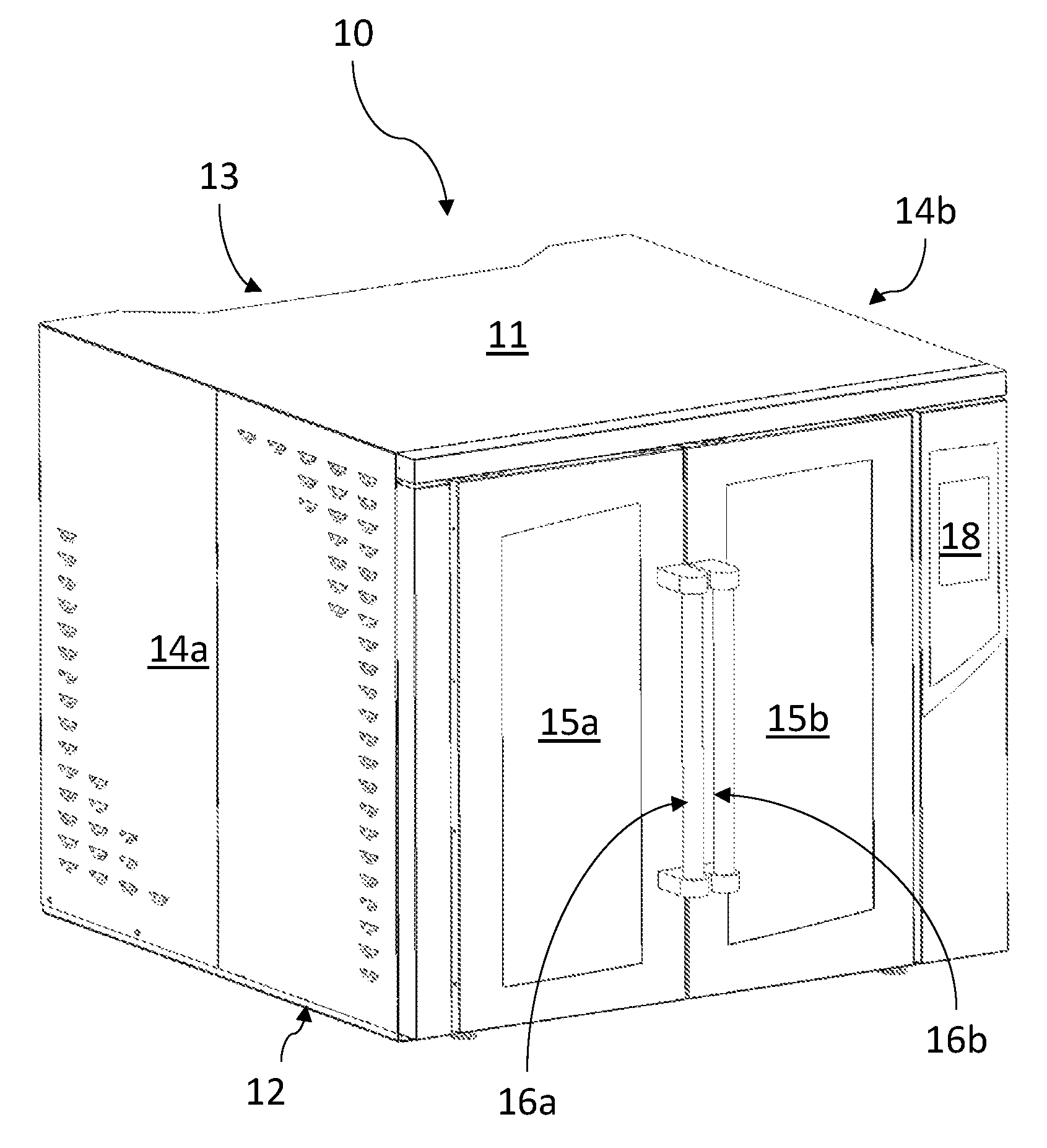
FIG. 1 is an isometric view of a convection oven, in accordance with an exemplary embodiment of the present invention.
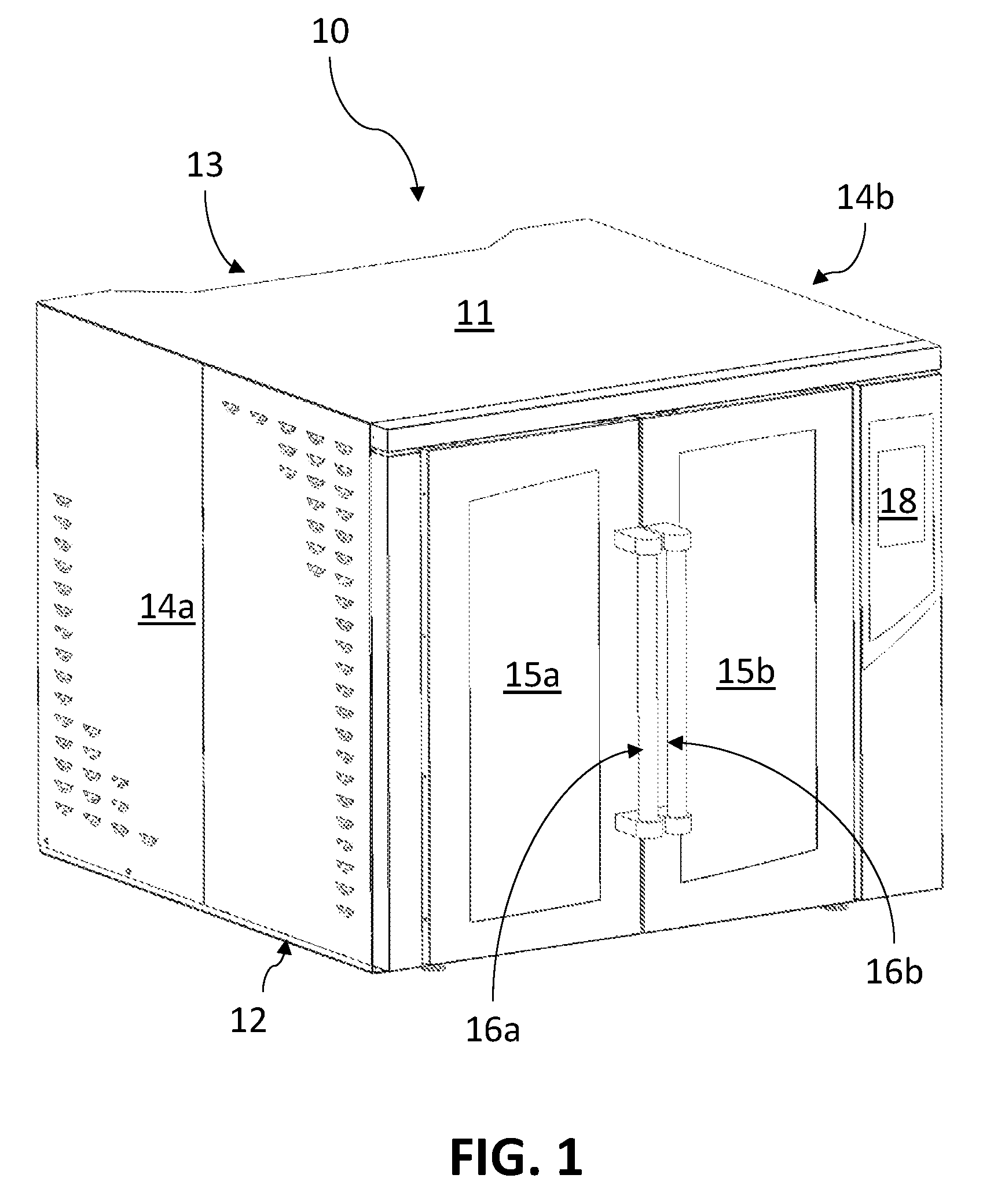
FIG. 2A is a front perspective view of an oven cavity of the convection oven from FIG. 1, with no air plenum placed therein, in accordance with an exemplary embodiment of the present invention.
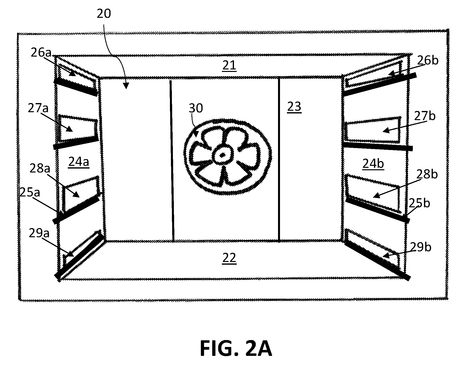
FIG. 2B is a front isometric view of the oven cavity from FIG. 2A, populated with air plenums in accordance with an exemplary embodiment of the present invention.
FIGS. 3A-3D are various cross-sectional views of an oven cavity populated with air plenums within the convection oven from FIG. 1, in accordance with an exemplary embodiment of the present invention.
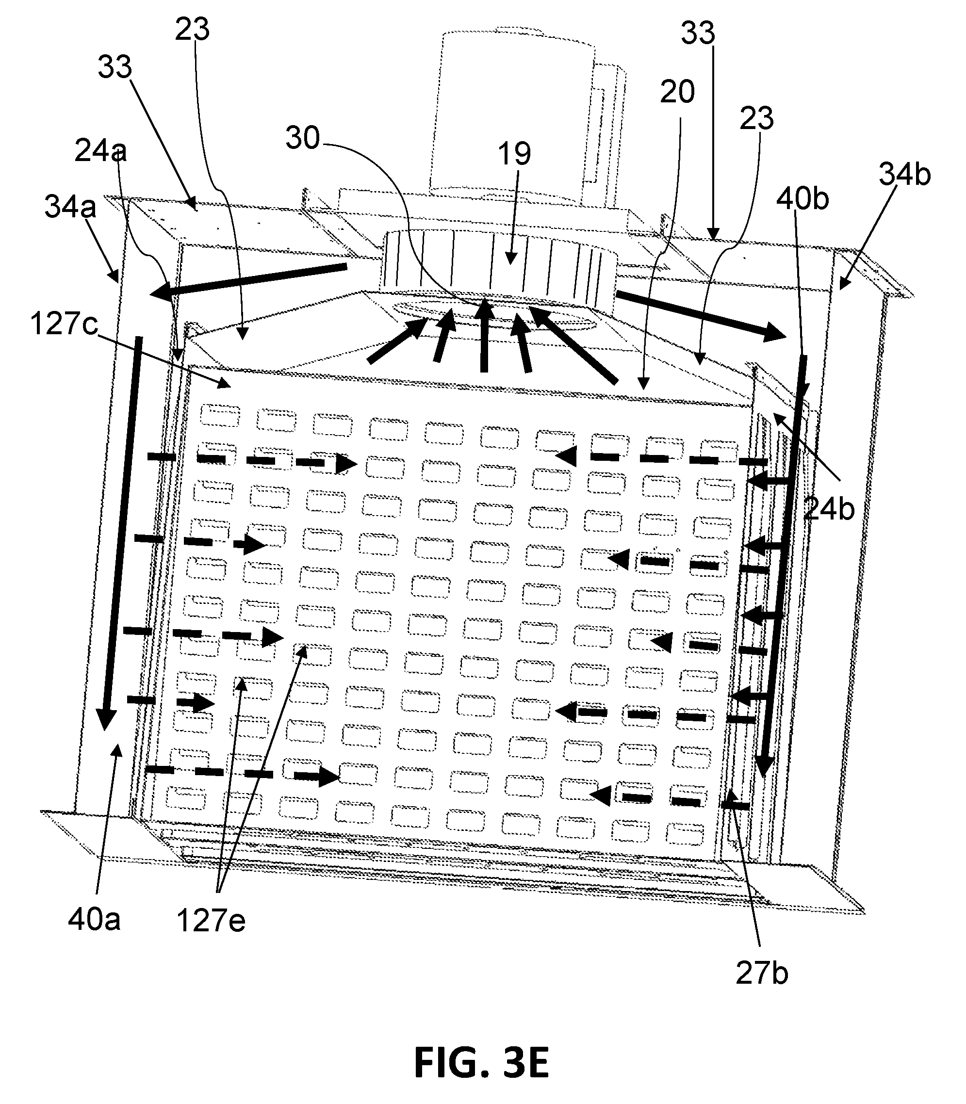
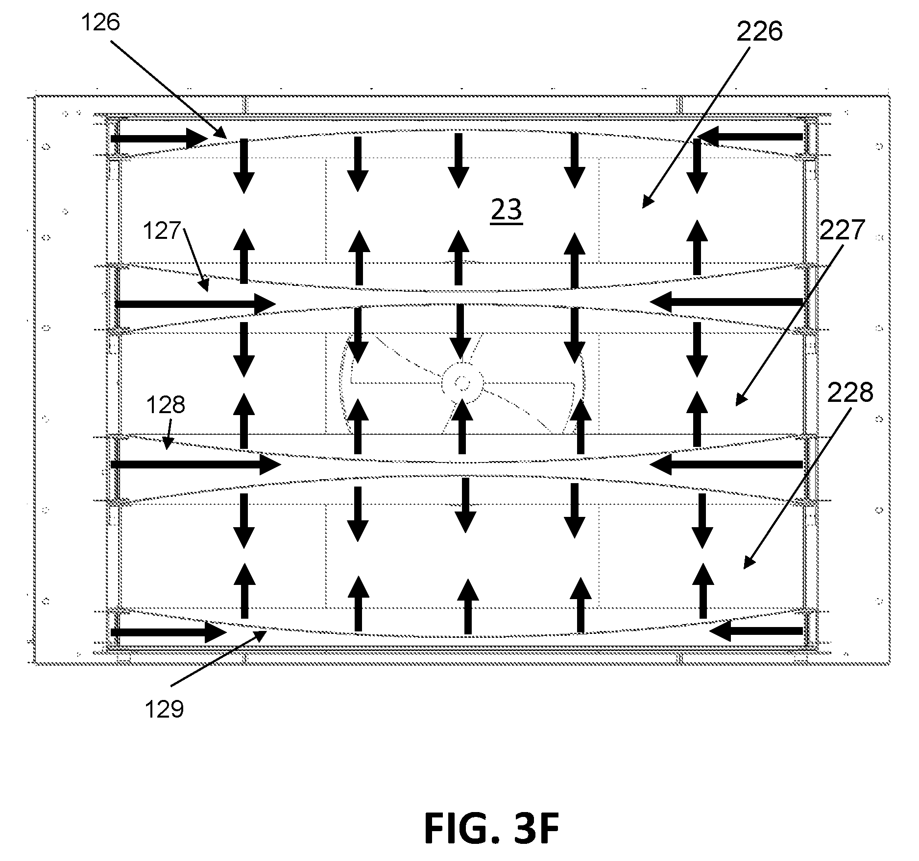
FIGS. 3E-3F illustrate exemplary directions of air flow within the oven cavity of the convection oven from FIG. 1.
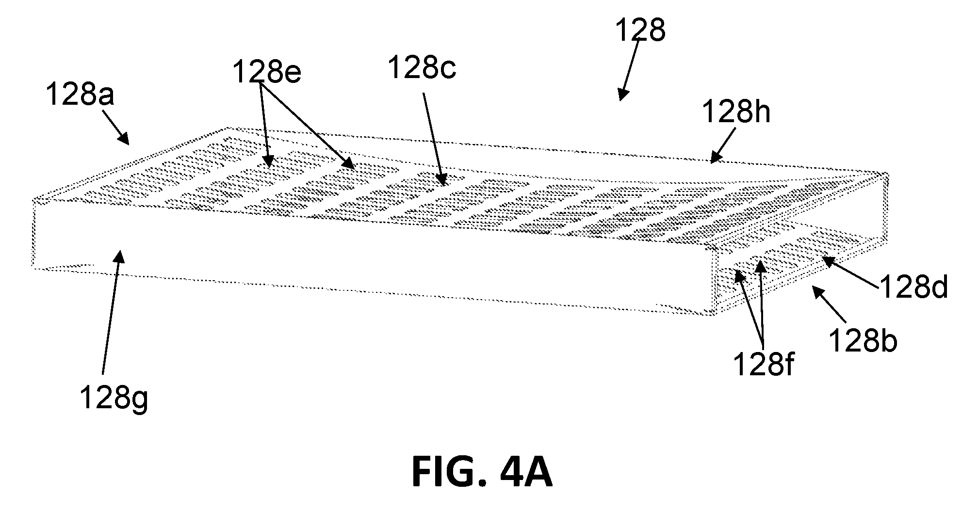
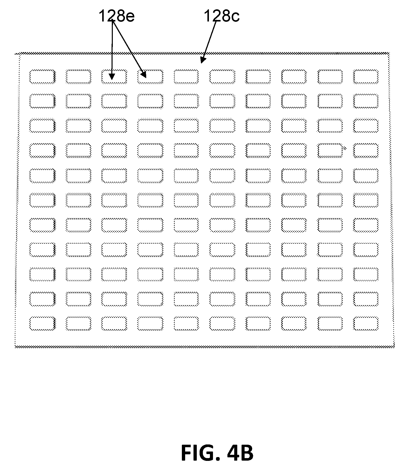
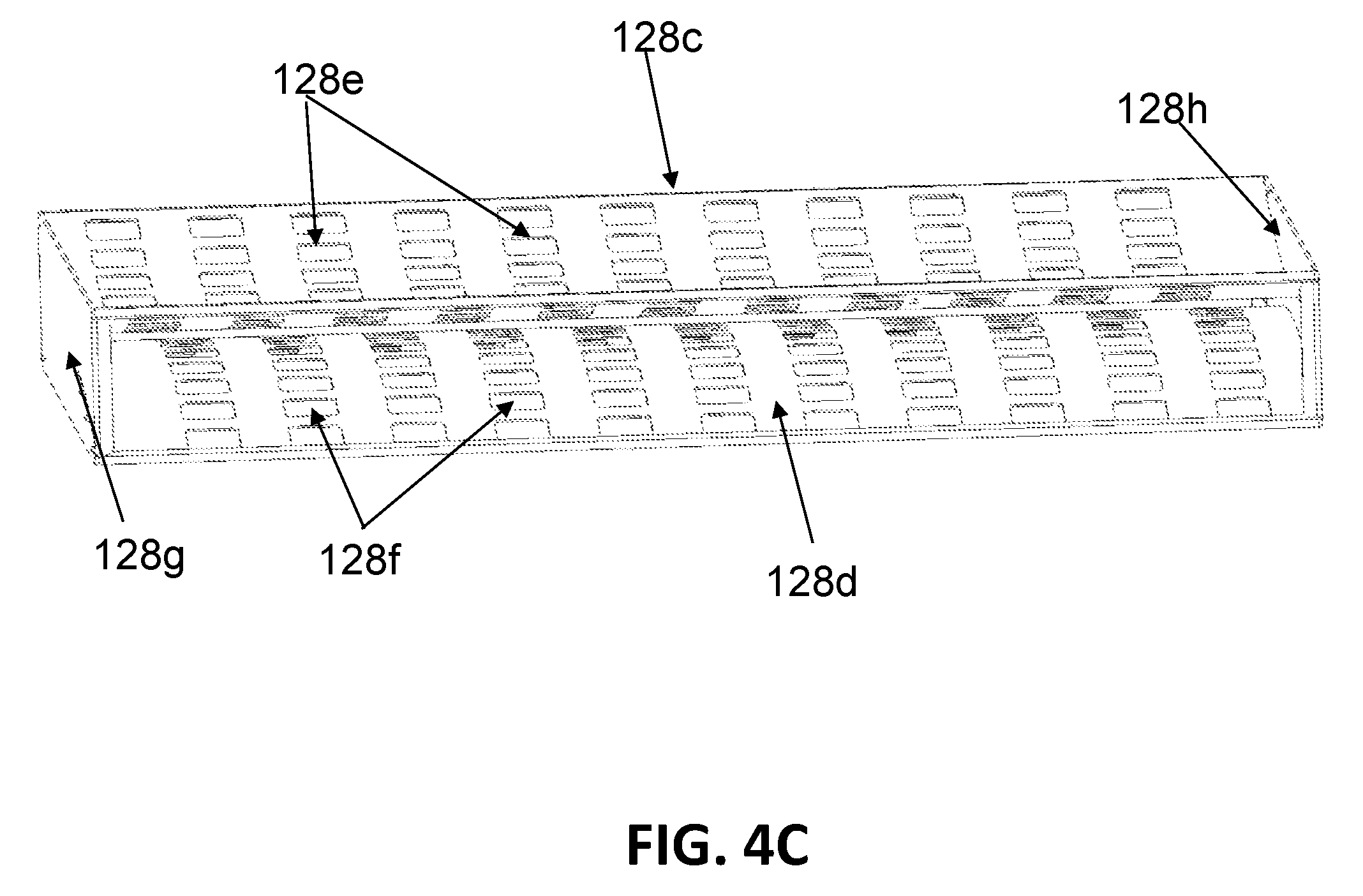
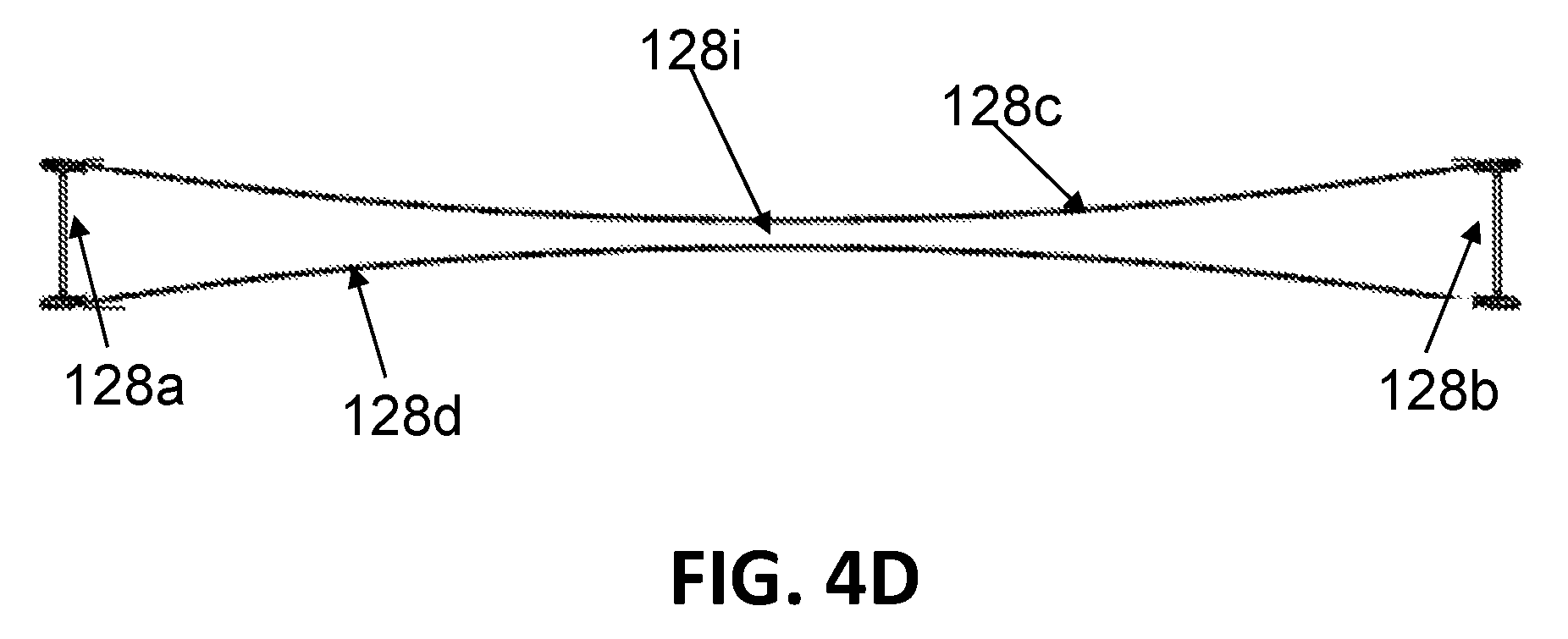
FIGS. 4A-4D are front isometric, top planar, side isometric, and front cross-sectional views of an intermediate air plenum, respectively, in accordance with an exemplary embodiment of the present invention.
DETAILED DESCRIPTION OF THE EXEMPLARY EMBODIMENTS
In the present disclosure, like reference numbers refer to like elements throughout the drawings, which illustrate various exemplary embodiments of the present invention.
Referring now to the drawings and in particular to FIG. 1, there is depicted an isometric view of a convection oven, in accordance with an exemplary embodiment of the present invention. As shown, a convection oven 10 includes a housing having a top panel 11, a bottom panel 12, a rear panel 13 and two side panels 14a, 14b.
A pair of oven doors 15a, 15b may form the front panel of the housing and are pivotally connected with side panels 14a, 14b, respectively, via hinges. Oven doors 15a and 15b may include handles 16a and 16b, respectively, for opening and closing the same, and a latch may be provided to keep doors 15a, 15b in a closed position. Door sensing switches (not shown) may be used to sense when oven doors 15a, 15b are being opened or closed.
In alternative embodiments, instead of a pair of oven doors, the oven may include a single oven door (not shown) which is pivotally connected with one of side panels 14a, 14b, top panel 11, or bottom panel 12 via hinges, or one or more bottom hinged doors (also not shown).
Convection oven 10 also includes a control panel 18, which may be implemented with one or more control knobs, one or more touchscreens, or a combination of a control knob and touchscreen technology. An operator can enter commands or cooking parameters, such as cooking temperature, cooking time, fan speed, etc., via control panel 18 to effectuate cooking controls on any food items placed within convection oven 10.
With reference now to FIGS. 2A-2B and 3A-3D, there are depicted various views of an oven cavity 20 within convection oven 10, in accordance with an exemplary embodiment of the present invention.
FIG. 2A provides a front perspective view of oven cavity 20 that has no air plenum placed therein. Oven cavity 20 is defined by a top cavity wall 21, a bottom cavity wall 22, a back cavity wall 23, and left and right side cavity walls 24a and 24b, along with oven doors 15a, 15b (shown in FIG. 1). The size of oven cavity 20 for an oven designed for the "full sized" market may be about 10 cubic feet in accordance with an exemplary embodiment of the present invention. Different dimensions would apply for oven cavities in smaller or larger sized ovens. Located on both side cavity walls 24a, 24b are multiple parallel rails 25a, 25b configured to support placement of one or more air plenums within oven cavity 20.
Also located on each of left and right side cavity walls 24a and 24b are one or more air channels for bringing heated air from one or more air blowers 19 (see, e.g., FIGS. 3D and 3E) within convection oven 10 into oven cavity 20. As shown in FIGS. 2A and 3A-3B, left side cavity wall 24a includes left side air channels 26a, 27a, 28a, 29a, which are placed in parallel and spaced vertically apart from each other. Likewise, right side cavity wall 24b includes right side air channels 26b, 27b, 28b, 29b, which are placed in parallel and spaced vertically apart from each other. Preferably, left side air channels 26a, 27a, 28a, 29a and right side air channels 26b, 27b, 28b, 29b are symmetrically placed on left and right side cavity walls 24a, 24b so that, as further described below, an air plenum placed within oven cavity 20 can receive heated air from a pair of left and right side air channels located at substantially the same vertical height (e.g., (26a, 26b), (27a, 27b), (28a, 28b), (29a, 29b)) through its left and right sides. Preferably, the size of each of left side air channels 26a, 27a, 28a, 29a is substantially the same as the size of its paired right side air channel 26b, 27b, 28b, 29b.
FIG. 2A shows that each of left and right side air channels 26a, 27a, 28a, 29a, 26b, 27b, 28b, 29b may comprise a single horizontally elongated rectangular opening. In alternative embodiments, each air channel may take various other shape or form, such as a plurality of rectangular or circular openings, or openings of other shapes.
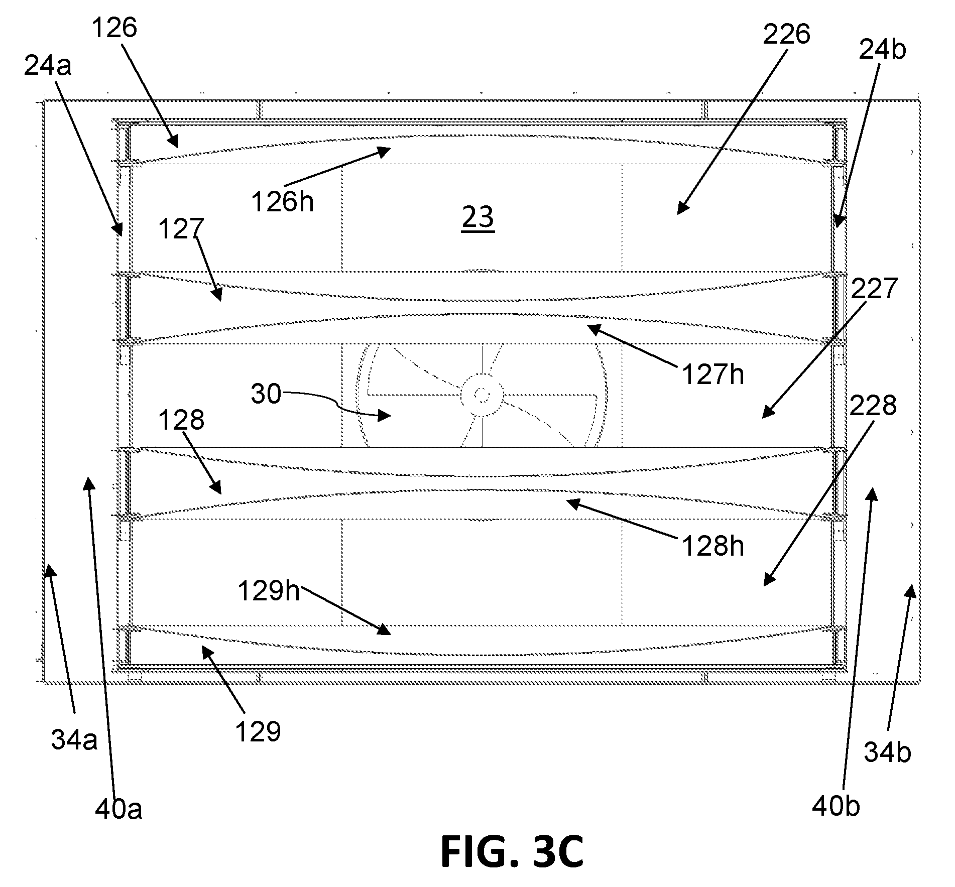
FIG. 2A also shows a return air opening 30 located on back cavity wall 23 of oven cavity 20 (see also FIG. 3D).
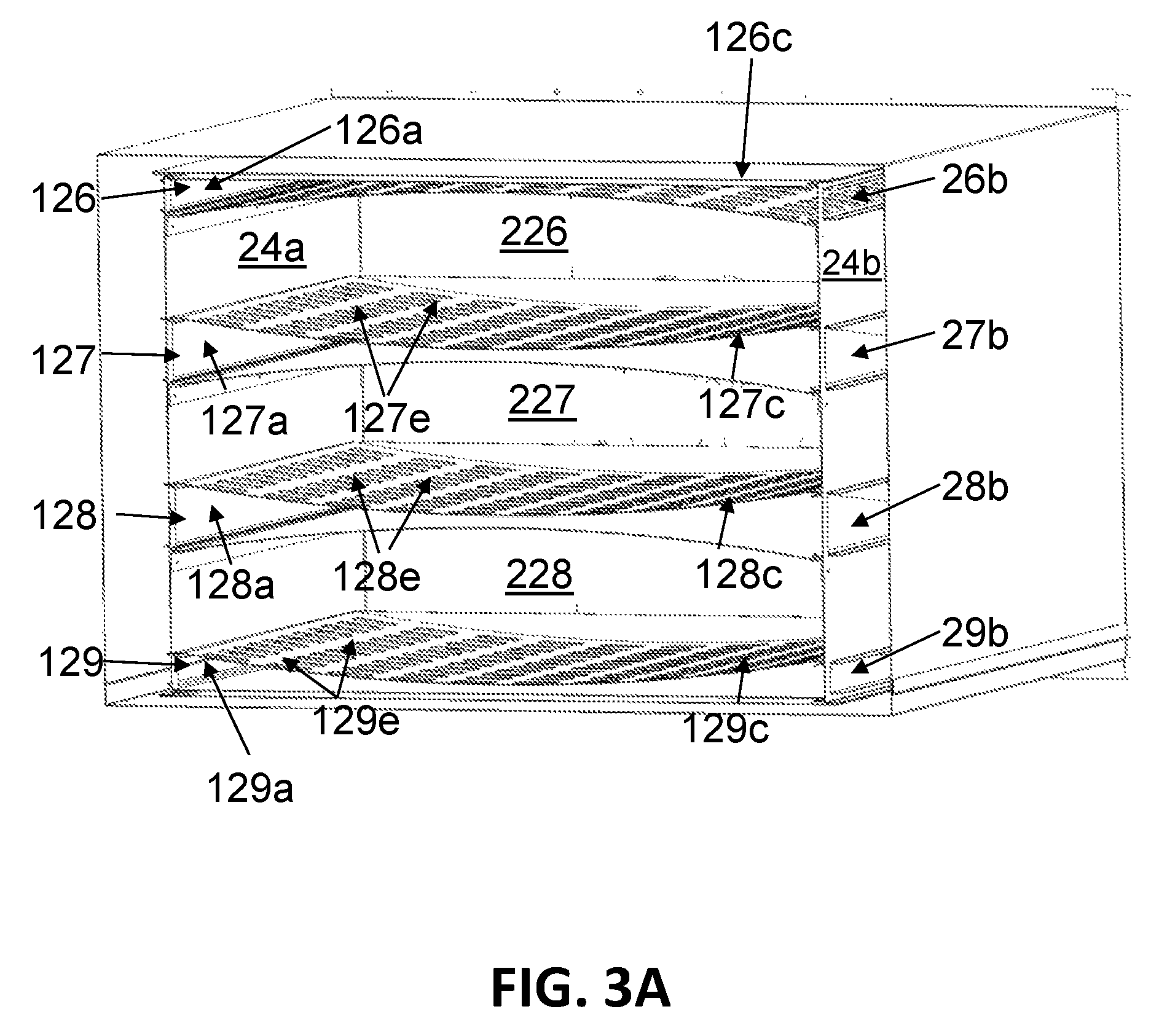
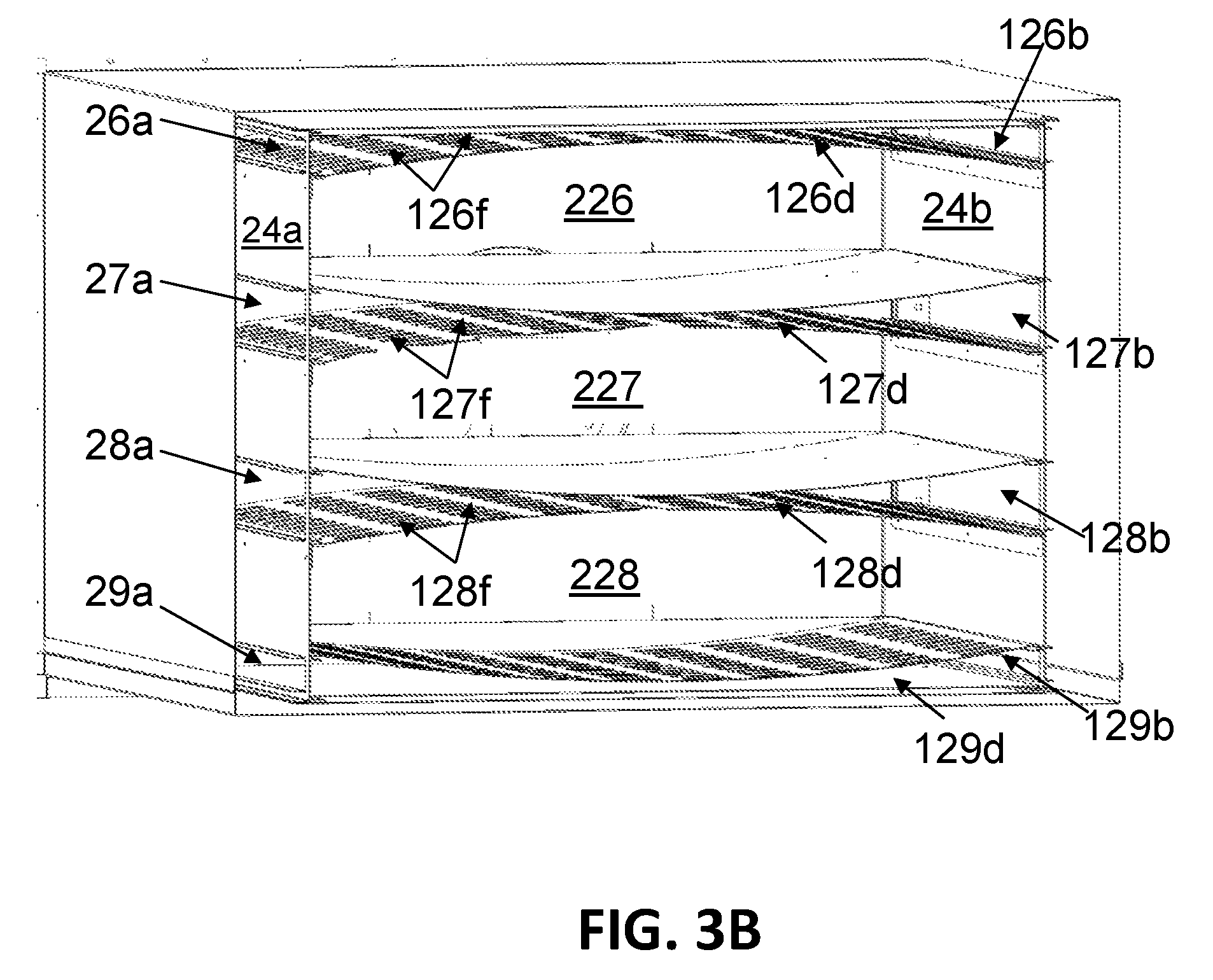
Referring now to FIGS. 2B and 3A-3C, oven cavity 20 may be populated with one or more air plenums. FIG. 2B provides a front isometric view of oven cavity 20 populated with a top air plenum 126, a bottom air plenum 129, and one or more intermediate air plenums 127, 128. FIGS. 3A-3C provide front cross-sectional views of air plenums 126, 127, 128, 129 placed in oven cavity 20. FIGS. 3A-3B also provide partial views of right side air channels 26b, 27b, 28b, 29b in right side cavity wall 24b and partial views of left side air channels 26a, 27a, 28a, 29a in left side cavity wall 24a of oven cavity 20.
As shown in FIG. 2B, intermediate air plenums 127, 128 divide oven cavity 20 into multiple cooking chambers 226, 227, 228 (e.g., three in this case). Top air plenum 126 and intermediate air plenum 127 define the top and the bottom of cooking chamber 226, respectively; intermediate air plenum 127 and intermediate air plenum 128 define the top and the bottom of cooking chamber 227, respectively; and intermediate air plenum 128 and bottom air plenum 129 define the top and the bottom of cooking chamber 228, respectively. The size of at least one of these cooking chambers 226, 227, 228 for an oven designed for the "full sized" market may range between 1.5 and 2.0 cubic feet in accordance with an exemplary embodiment of the present invention. Different dimensions would apply for cooking chambers in smaller or larger sized ovens.
Each of air plenums 126, 127, 128, 129 comprises a front surface 126g, 127g, 128g, 129g (see FIG. 2B), a rear surface 126h, 127h, 128h, 129h (see FIG. 3C) a top plenum surface 126c, 127c, 128c, 129c (see FIG. 3A), a bottom plenum surface 126d, 127d, 128d, 129d (see FIG. 3B), a left side having a left side air inlet 126a, 127a, 128a, 129a (see FIG. 3A), and a right side having a right side air inlet 126b, 127b, 128b, 129b (see FIG. 3B), all of which define exterior surface and interior space of the air plenum. Preferably, the front and rear surfaces of each air plenum 126, 127, 128, 129 are substantially air impermeable so as to permit no air flow through them.
When each of air plenums 126, 127, 128, 129 is placed within oven cavity 20, front surface 126g, 127g, 128g, 129g of air plenum 126, 127, 128, 129 faces oven doors 15a, 15b; and rear surface 126h, 127h, 128h, 129h faces back cavity wall 23 of oven cavity 20.
As shown in FIGS. 2B and 3A-3C, intermediate air plenums 127, 128 may be substantially identical to each other in structure. In alternative embodiments, each of intermediate air plenums may be configured differently in structure.
As shown in FIGS. 3A-3B, left side air inlet 126a of top air plenum 126 is connected or placed adjacent to left side air channel 26a located on left side cavity wall 24a of oven cavity 20 and right side air inlet 126b of top air plenum 126 is connected or placed adjacent to right side air channel 26b located on right side cavity wall 24b of oven cavity 20, so that heated air flowing from left and right side air channels 26a, 26b can enter the interior space of top air plenum 126 through left and right side air inlets 126a, 126b, respectively.
As also shown in FIGS. 3A-3B, left side air inlet 127a of intermediate air plenum 127 is connected or placed adjacent to left side air channel 27a located on left side cavity wall 24a of oven cavity 20 and right side air inlet 127b of intermediate air plenum 127 is connected or placed adjacent to right side air channel 27b located on right side cavity wall 24b of oven cavity 20, so that heated air flowing from left and right side air channels 27a, 27b can enter the interior space of intermediate air plenum 127 through left and right side air inlets 127a, 127b, respectively. Likewise, left side air inlet 128a of intermediate air plenum 128 is connected or place adjacent to left side air channel 28a located on left side cavity wall 24a of oven cavity 20 and right side air inlet 128b of intermediate air plenum 128 is connected or placed adjacent to right side air channel 28b located on right side cavity wall 24b of oven cavity 20, so that heated air flowing from left and right side air channels 28a, 28b can enter the interior space of intermediate air plenum 128 through left and right side air inlets 128a, 128b, respectively.
As also shown in FIGS. 3A-3B, left side air inlet 129a of bottom air plenum 129 is connected or placed adjacent to left side air channel 29a located on left side cavity wall 24a of oven cavity 20 and right side air inlet 129b of bottom air plenum 129 is connected or placed adjacent to right side air channel 29b located on right side cavity wall 24b of oven cavity 20, so that heated air flowing from left and right side air channels 29a, 29b can enter the interior space of bottom air plenum 129 through left and right side air inlets 129a, 129b, respectively.
Each of air plenums 126, 127, 128, 129 may be removable from oven cavity 20. In that case, left and right side air inlets 126a, 126b of top air plenum 126 are removably connected to left and right side air channels 26a, 26b, respectively; left and right side air inlets 127a, 127b of intermediate air plenum 127 are removably connected to left and right side air channels 27a, 27b, respectively; left and right side air inlets 128a, 128b of intermediate air plenum 128 are removably connected to left and right side air channels 28a, 28b, respectively; and left and right side air inlets 129a, 129b of bottom air plenum 129 are removably connected to left and right side air channels 29a, 29b, respectively. In addition, each of left and right side air channels 26a, 27a, 28a, 29a, 26b, 27b, 28b, 29b may be coverable by a flap (not shown) if the corresponding air plenum is removed from oven cavity 20 and is no longer connected to the air channel.
In alternative embodiments, some or all of air plenums 126, 127, 128, 129 may be permanently fixed to oven cavity 20. In that case, left and right side air inlets 126a, 126b of top air plenum 126 may be removably or permanently connected to left and right side air channels 26a, 26b, respectively; left and right side air inlets 127a, 127b of intermediate air plenum 127 may be removably or permanently connected to left and right side air channels 27a, 27b, respectively; left and right side air inlets 128a, 128b of intermediate air plenum 128 may be removably or permanently connected to left and right side air channels 28a, 28b, respectively; and left and right side air inlets 129a, 129b of bottom air plenum 129 may be removably or permanently connected to left and right side air channels 29a, 29b, respectively. For example, top and bottom air plenums 126, 129 may be permanently fixed to oven cavity 20, while intermediate air plenums 127, 128 may be removable from oven cavity 20.
If intermediate air plenums 127, 128 are removable from oven cavity 20, the number and the size of cooking chambers within oven cavity 20 can be changed or adjusted by removing one or more intermediate air plenums from oven cavity 20. For example, by removing intermediate air plenum 128, oven cavity 20 has a relatively large cooking chamber on the bottom (with the combined space for cooking chambers 227 and 228) and a smaller cooking chamber 226.
As shown in FIGS. 3A-3B, the size and shape of each of left side air inlets 126a, 127a, 128a, 129a of air plenums 126, 127, 128, 129 may substantially match the size and shape of the corresponding left side air channel 26a, 27a, 28a, 29a from which the left side air inlet receives heated air. Likewise, the size and shape of each of right side air inlets 126b, 127b, 128b, 129b may substantially match the size and shape of the corresponding right side air channel 26b, 27b, 28b, 29b from which the right side air inlet receives heated air.
In alternative embodiments, the size of each of left and right side air inlets of the air plenums may be smaller or larger than the size of the air channel from which the air inlet receives heated air. In further alternative embodiments, the shape of each of left and right air inlets of the air plenums may be different from the shape of the air channel from which the air inlet receives heated air. For example, an air channel on the side cavity wall of oven cavity 20 may comprise a plurality of circular openings, while the corresponding air inlet of an air plenum may be in the shape of an elongated rectangular opening.
As shown in FIGS. 3A-3C, air plenums 126, 127, 128, 129 may be placed relative to left and right side cavity walls 24a, 24b within oven cavity 20 in such a way that heated air coming from left side air channels 26a, 27a, 28a, 29a, and right side air channels 26b, 27b, 28b, 29b cannot flow into oven cavity 20 except through air plenums 126, 127, 128, 129.
In alternative embodiments, left and right side cavity walls 24a and 24b of oven cavity 20 may include additional separate openings (not shown) to allow additional air flow into oven cavity 20 from the left and right sides.
As shown in FIGS. 3A-3B, each intermediate air plenum 127, 128 may be configured to direct heated air both upwards and downwards. Top plenum surface 127c of intermediate air plenum 127 has a plurality of top air outlets 127e that are configured to direct a portion of heated air received from left and right side air channels 27a, 27b through left and right side air inlets 127a, 127b upwards into cooking chamber 226. Bottom plenum surface 127d of intermediate air plenum 127 has a plurality of bottom air outlets 127f that are configured to direct a portion of heated air received from left and right side air channels 27a, 27b through left and right side air inlets 127a, 127b downwards into cooking chamber 227.
Likewise, top plenum surface 128c of intermediate air plenum 128 has a plurality of top air outlets 128e that are configured to direct a portion of heated air received from left and right side air channels 28a, 28b through left and right side air inlets 128a, 128b upwards into cooking chamber 227. Bottom plenum surface 128d of intermediate air plenum 128 has a plurality of bottom air outlets 128f that are configured to direct a portion of heated air received from left and right side air channels 28a, 28b through left and right side air inlets 128a, 128b downwards into cooking chamber 228.
On the other hand, top air plenum 126 and bottom air plenum 129 are configured to direct heated air in only one direction--upwards or downwards. Bottom plenum surface 126d of top air plenum 126 has a plurality of bottom air outlets 126f that are configured to direct heated air received from left and right side air channels 26a, 26b through left and right side air inlets 126a, 126b downwards into cooking chamber 226. Top plenum surface 129c of bottom air plenum 129 has a plurality of top air outlets 129e that are configured to direct heated air received from left and right side air channels 29a, 29b through left and right side air inlets 129a, 129b upwards into cooking chamber 228.
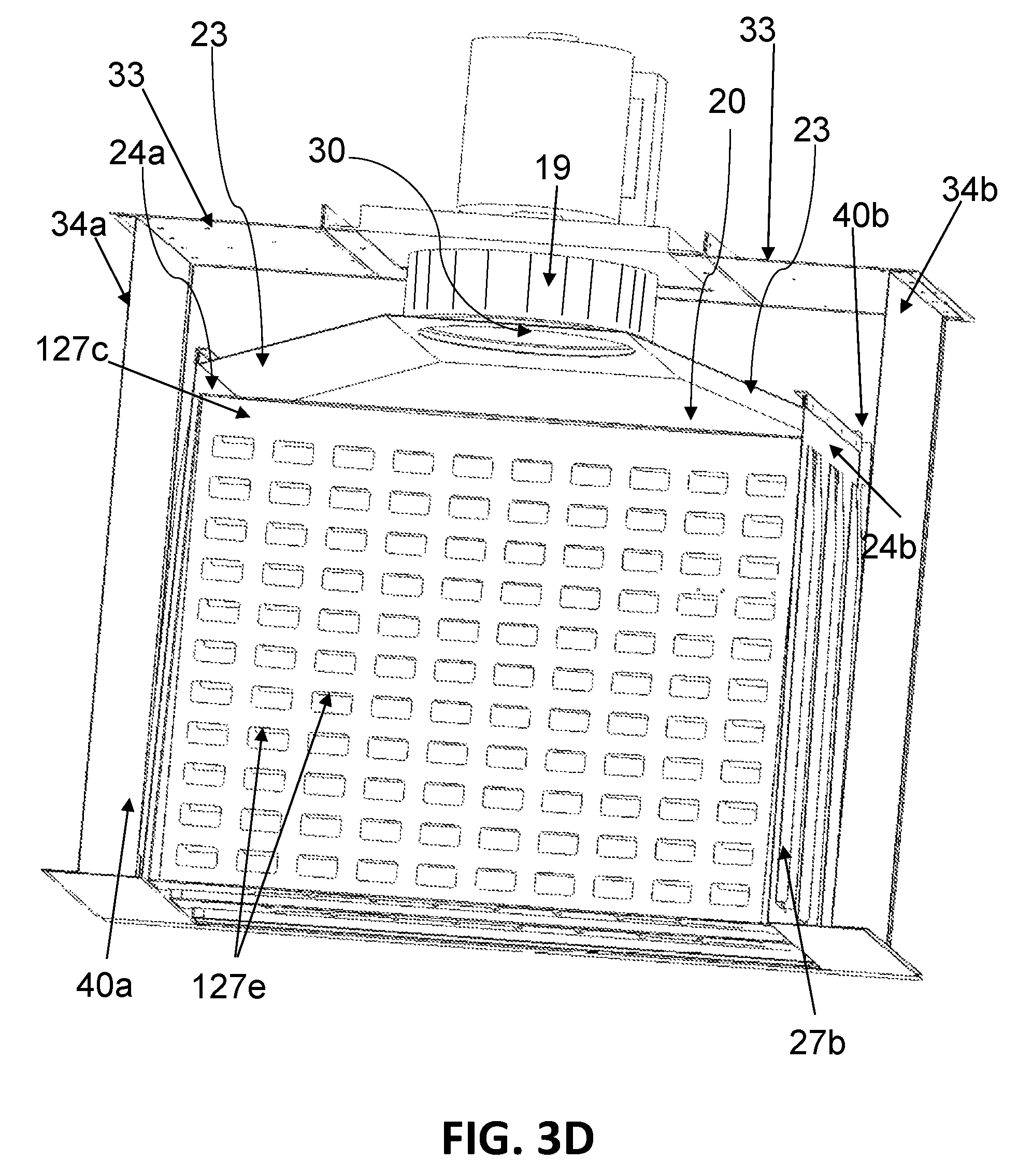
With reference now to FIG. 3D, there is depicted a top cross-sectional view of oven cavity 20, exposing top plenum surface 127c and top air outlets 127e of intermediate air plenum 127. FIG. 3D shows an exemplary supply air path in which a supply air exits an air blower 19 and flows through both a left supply channel 40a and a right supply channel 40b to reach the air channels (e.g., right side air channel 27b) located on left and right side cavity walls 24a, 24b of oven cavity 20. As shown in FIGS. 3C-3D, a back channel wall 33 and left and right side channel walls 34a, 34b of convection oven 10 surround oven cavity 20. Left supply channel 40a is defined by the portions of back channel wall 33 and back cavity wall 23 located to the left of air blower 19, left side channel wall 34a, and left side cavity wall 24a. Right supply channel 40b is defined by the portions of back channel wall 33 and back cavity wall 23 located to the right of air blower 19, right side channel wall 34b, and right side cavity wall 24b.
FIG. 3D also shows an exemplary return air path from oven cavity 20 to air blower 19 via return air opening 30 located on back cavity wall 23 of oven cavity 20.
FIGS. 3E-3F illustrate directions of air flow (indicated by arrows) when convection oven 10 of FIGS. 3A-3D is in operation in accordance with an exemplary embodiment of the present invention. As shown in FIG. 3E, one or more air blowers 19 in convection oven 10 send heated air to both left and right supply channels 40a and 40b and the heated air reaches left and right side air channels 26a, 27a, 28a, 29a, 26b, 27b, 28b, 29b located on left and right side cavity walls 24a, 24b of oven cavity 20. The heated air then enters the interior space of air plenums 126, 127, 128, 129 via left and right side air channels 26a, 27a, 28a, 29a, 26b, 27b, 28b, 29b.
Referring now to FIG. 3F, top air plenum 126 receives the heated air from left and right side air channels 26a, 26b through left and right side air inlets 126a, 126b, and then direct the heated air downwards into cooking chamber 226 via bottom air outlets 126f in bottom plenum surface 126d.
Intermediate air plenum 127 receives the heated air from left and right side air channels 27a, 27b through left and right side air inlets 127a, 127b, and then (1) direct a portion of the heated air upwards into cooking chamber 226 via top air outlets 127e in top plenum surface 127c and (2) direct a portion of the heated air downwards into cooking chamber 227 via bottom air outlets 127f in bottom plenum surface 127d.
Intermediate air plenum 128 receives the heated air from left and right side air channels 28a, 28b through left and right side air inlets 128a, 128b, and then (1) direct a portion of the heated air upwards into cooking chamber 227 via top air outlets 128e in top plenum surface 128c and (2) direct a portion of the heated air downwards into cooking chamber 228 via bottom air outlets 128f in bottom plenum surface 128d.
Bottom air plenum 129 receives the heated air from left and right side air channels 29a, 29b through left and right side air inlets 129a, 129b, and then direct the heated air upwards into cooking chamber 228 via top air outlets 129e in top plenum surface 129c.
In this way, the heated air changes its direction from a generally horizontal path to a generally vertical path as it passes through air plenums 126, 127, 128, 129 and enters cooking chambers 226, 227, 228 within oven cavity 20, as illustrated in FIG. 3F.
Referring now to FIG. 3E, the air in oven cavity 20 may be returned to the air blower 19 via return air opening 30 located on back cavity wall 23 of oven cavity 20.
Preferably, the interior space of each of air plenums 126, 127, 128, 129 is shaped in a way that facilitates even distribution of heated air flowing into oven cavity 20. For example, as shown in FIGS. 3A-3C, top plenum surface 127c, 128c and bottom plenum surface 127d, 128d of intermediate air plenum 127, 128 that respectively define the top and the bottom of the interior space of the intermediate air plenum may be shaped in a way that optimizes even distribution of heated air flow into oven cavity 20. Likewise, bottom plenum surface 126d of top air plenum 126 and top plenum surface 129c of bottom air plenum 129 may be shaped in a way that optimizes even distribution of heated air flow into oven cavity 20.
In accordance with an exemplary embodiment shown in FIGS. 3A-3C, each of top plenum surface 127c, 128c and bottom plenum surface 127d, 128d of intermediate air plenum 127, 128, bottom plenum surface 126d of top air plenum 126, and top plenum surface 129c of bottom air plenum 129 may be curved so that (1) a vertical spacing between top plenum surface 126c, 127c, 128c, 129c and the bottom plenum surface 126d, 127d, 128d, 129d at left side air inlet 126a, 127a, 128a, 129a of each air plenum 126, 127, 128, 129 is substantially equal to a vertical spacing between top plenum surface 126c, 127c, 128c, 129c and the bottom plenum surface 126d, 127d, 128d, 129d at right side air inlet 126b, 127b, 128b, 129b; and (2) the vertical spacing between top plenum surface 126c, 127c, 128c, 129c and the bottom plenum surface 126d, 127d, 128d, 129d at left side air inlet 126a, 127a, 128a, 129a is greater than a vertical spacing between top plenum surface 126c, 127c, 128c, 129c and the bottom plenum surface 126d, 127d, 128d, 129d at a midpoint of the air plenum 126, 127, 128, 129.
For example, as shown in FIGS. 3A-3C (and also in FIG. 4D), top plenum surface 127c, 128c and bottom plenum surface 127d, 128d of intermediate air plenum 127, 128 may be shaped so that their front cross-section comprises two substantially hyperbolic curves, which are curved toward each other at a midpoint of the intermediate air plenum.
Referring now to FIGS. 4A-4D, there are depicted various views of intermediate air plenum 128 in accordance with an exemplary embodiment of the present invention. FIG. 4A is a front isometric view of intermediate air plenum 128 comprising substantially air impermeable front and rear surfaces 128g, 128h, top plenum surface 128c having a plurality of top air outlets 128e, bottom plenum surface 128d having a plurality of bottom air outlets 128f, left side air inlet 128a, and right side air inlet 128b.
FIG. 4B is a top planar view of intermediate air plenum 128 showing top plenum surface 128c having a plurality of top air outlets 128e. Preferably, bottom plenum surface 128d of intermediate air plenum 128 has substantially the same structure as top plenum surface 128c. In that case, FIG. 4B can be a bottom planar view of intermediate air plenum 128 showing bottom plenum surface 128d having a plurality of bottom air outlets 128f. As an example, the size of each top air outlet 128e (or bottom air outlet 1281) may range between 1.25 and 2.5 square inches. While each of top air outlets 128e (or bottom air outlets 1281) shown in FIG. 4B has a substantially rectangular shape, it may have a different shape in alternative embodiments, such as square, circle, ellipse, rhombus, trapezoid, hexagon, or other type of regular or irregular geometric shape.
FIG. 4C is a side isometric view of intermediate air plenum 128, looking into right side air inlet 128b. Top plenum surface 128c and bottom plenum surface 128d are curved toward each other at the midpoint of intermediate air plenum 128, and top air outlets 128e and bottom air outlets 128f are partially visible. As shown in FIG. 4C, the arrangements of top air outlets 128e and bottom air outlets 128f may be offset from each other so that air changing its direction from horizontal to upwards can push off from the solid surface of bottom plenum surface 128d and likewise air changing its direction from horizontal to downwards can push off from the solid surface of top plenum surface 128c. If the arrangements of top air outlets 128e and bottom air outlets 128f are aligned with each other, air moving upwards through top air outlets 128e would be pushing off from air moving downwards through bottom air outlets 128f. By offsetting the arrangements of top air outlets 128e and bottom air outlets 128f of intermediate air plenum 128, increased air velocity can be achieved, which would result in reduced cook times.
FIG. 4D is a front cross-sectional view of intermediate air plenum 128, showing the cross section of top plenum surface 128c and bottom plenum surface 128d forming two substantially hyperbolic curves, curving toward each other at a midpoint 1281 of intermediate air plenum 128. This configuration optimizes even distribution of heated air flow into the oven cavity by forcing the heated air received through left and right side air inlets 128a, 128b into the increasingly narrower interior space as it approaches midpoint 1281 of intermediate air plenum 128.
In accordance with an exemplary embodiment of the present invention, the front and rear width of intermediate air plenum 128 for an oven designed for the "full sized" market may range between 20 inches and 30 inches (e.g., 26.8 inches). The right and left side length of intermediate air plenum 128 (e.g., horizontal width of left/right side air inlet 128a, 128b) for an oven designed for the "full sized" market may range between 15 inches and 25 inches (e.g., 21 inches). Different dimensions would apply for the front and rear width and the right and left side length of intermediate air plenum in smaller or larger sized ovens.
In addition, the vertical spacing between top plenum surface 128c and bottom plenum surface 128d of intermediate air plenum 128 at left side air inlet 128a and at right side air inlet 128b (e.g., vertical height of left/right side air inlet 128a, 128b) for an oven designed for the "full sized" market may range between 1.5 inches and 3 inches (e.g., 2 inches), and the vertical spacing between top plenum surface 128c and bottom plenum surface 128d at midpoint 1281 of intermediate air plenum 128 for such an oven may range between 0.25 inches and 1.25 inches (e.g., 0.7 inches). Different dimensions would apply for the vertical spacing between top plenum surface and bottom plenum surface of intermediate air plenum in smaller or larger sized ovens.
As has been described, the present invention provides an improved convection oven providing a more uniform flow of heated air within the oven cavity.
While this invention has been described in conjunction with exemplary embodiments outlined above and illustrated in the drawings, it is evident that many alternatives, modifications and variations in form and detail will be apparent to those skilled in the art. Accordingly, the exemplary embodiments of the invention, as set forth above, are intended to be illustrative, not limiting, and the spirit and scope of the present invention is to be construed broadly and limited only by the appended claims, and not by the foregoing specification.
* * * * *
References
D00000
D00001
D00002
D00003
D00004
D00005
D00006
D00007
D00008
D00009
D00010
D00011
D00012
D00013
XML
uspto.report is an independent third-party trademark research tool that is not affiliated, endorsed, or sponsored by the United States Patent and Trademark Office (USPTO) or any other governmental organization. The information provided by uspto.report is based on publicly available data at the time of writing and is intended for informational purposes only.
While we strive to provide accurate and up-to-date information, we do not guarantee the accuracy, completeness, reliability, or suitability of the information displayed on this site. The use of this site is at your own risk. Any reliance you place on such information is therefore strictly at your own risk.
All official trademark data, including owner information, should be verified by visiting the official USPTO website at www.uspto.gov. This site is not intended to replace professional legal advice and should not be used as a substitute for consulting with a legal professional who is knowledgeable about trademark law.