Re-entry stylet for catheter
Simpson , et al.
U.S. patent number 10,335,173 [Application Number 14/424,266] was granted by the patent office on 2019-07-02 for re-entry stylet for catheter. This patent grant is currently assigned to Avinger, Inc.. The grantee listed for this patent is Avinger, Inc.. Invention is credited to Myra L. Fabro, Priyanshu Gupta, Theodore W. Ketai, John B. Simpson, Eduardo Sucgang.


View All Diagrams
| United States Patent | 10,335,173 |
| Simpson , et al. | July 2, 2019 |
Re-entry stylet for catheter
Abstract
A stylet for re-entry into a vessel includes an elongate body including a proximal portion, a middle curved portion, a pointed distal end, and a longitudinal axis extending through the proximal portion, the middle curved portion, and the pointed distal end. The proximal portion and the middle curved portion have substantially circular cross-sections. The middle curved portion has a pre-shaped curve along the longitudinal axis configured to match a curve of an occlusion-crossing device. The pointed distal end has an s-curve along the longitudinal axis and a flattened portion along the longitudinal axis, the flattened portion having a substantially oblong cross-section.
| Inventors: | Simpson; John B. (Woodside, CA), Fabro; Myra L. (San Jose, CA), Sucgang; Eduardo (South San Francisco, CA), Gupta; Priyanshu (Palo Alto, CA), Ketai; Theodore W. (San Francisco, CA) | ||||||||||
|---|---|---|---|---|---|---|---|---|---|---|---|
| Applicant: |
|
||||||||||
| Assignee: | Avinger, Inc. (Redwood City,
CA) |
||||||||||
| Family ID: | 50237521 | ||||||||||
| Appl. No.: | 14/424,266 | ||||||||||
| Filed: | March 15, 2013 | ||||||||||
| PCT Filed: | March 15, 2013 | ||||||||||
| PCT No.: | PCT/US2013/032196 | ||||||||||
| 371(c)(1),(2),(4) Date: | February 26, 2015 | ||||||||||
| PCT Pub. No.: | WO2015/039096 | ||||||||||
| PCT Pub. Date: | March 13, 2014 |
Prior Publication Data
| Document Identifier | Publication Date | |
|---|---|---|
| US 20150320975 A1 | Nov 12, 2015 | |
Related U.S. Patent Documents
| Application Number | Filing Date | Patent Number | Issue Date | ||
|---|---|---|---|---|---|
| 61697726 | Sep 6, 2012 | ||||
| Current U.S. Class: | 1/1 |
| Current CPC Class: | A61M 25/0041 (20130101); A61M 25/0102 (20130101); A61M 25/0194 (20130101); A61B 17/22 (20130101); A61M 2025/0197 (20130101); A61B 2017/22095 (20130101) |
| Current International Class: | A61M 25/00 (20060101); A61M 25/01 (20060101); A61B 17/22 (20060101) |
| Field of Search: | ;604/510 |
References Cited [Referenced By]
U.S. Patent Documents
| 3908637 | September 1975 | Doroshow |
| 4178935 | December 1979 | Gekhaman et al. |
| 4487206 | December 1984 | Aagard |
| 4527553 | July 1985 | Upsher |
| 4552554 | November 1985 | Gould et al. |
| 4621353 | November 1986 | Hazel et al. |
| 4639091 | January 1987 | Huignard et al. |
| 4654024 | March 1987 | Crittenden et al. |
| 4686982 | August 1987 | Nash |
| 4691708 | September 1987 | Kane |
| 4771774 | September 1988 | Simpson et al. |
| 4841977 | June 1989 | Griffith et al. |
| 4857046 | August 1989 | Stevens et al. |
| 4920961 | May 1990 | Grossi et al. |
| 4926858 | May 1990 | Gifford, III et al. |
| 5000185 | March 1991 | Yock |
| 5018529 | May 1991 | Tenerz et al. |
| 5041082 | August 1991 | Shiber |
| 5047040 | September 1991 | Simpson et al. |
| 5085662 | February 1992 | Willard |
| 5099850 | March 1992 | Matsui et al. |
| 5178153 | January 1993 | Einzig |
| 5182291 | January 1993 | Gubin et al. |
| 5190050 | March 1993 | Nitzsche |
| 5192291 | March 1993 | Pannek, Jr. |
| 5312415 | May 1994 | Palermo |
| 5312425 | May 1994 | Evans et al. |
| 5321501 | June 1994 | Swanson et al. |
| 5333142 | July 1994 | Scheps |
| 5358472 | October 1994 | Vance et al. |
| 5366464 | November 1994 | Belknap |
| 5383460 | January 1995 | Jang et al. |
| 5383467 | January 1995 | Auer et al. |
| 5425273 | June 1995 | Chevalier |
| 5429136 | July 1995 | Milo et al. |
| 5431673 | July 1995 | Summers et al. |
| 5437284 | August 1995 | Trimble |
| 5459570 | October 1995 | Swanson et al. |
| 5460168 | October 1995 | Masubuchi et al. |
| 5465147 | November 1995 | Swanson |
| 5507795 | April 1996 | Chiang et al. |
| 5556405 | September 1996 | Lary |
| 5607394 | March 1997 | Andersen |
| 5620426 | April 1997 | Braithwaite |
| 5632754 | May 1997 | Farley et al. |
| 5632755 | May 1997 | Nordgren et al. |
| 5674232 | October 1997 | Halliburton |
| 5681336 | October 1997 | Clement et al. |
| 5690634 | November 1997 | Muller et al. |
| 5722403 | March 1998 | McGee et al. |
| 5728148 | March 1998 | Bostrom |
| 5795295 | August 1998 | Hellmuth et al. |
| 5807339 | September 1998 | Bostrom et al. |
| 5830145 | November 1998 | Tenhoff |
| 5836957 | November 1998 | Schulz et al. |
| 5843050 | December 1998 | Jones et al. |
| 5843103 | December 1998 | Wulfman |
| 5868778 | February 1999 | Gershony et al. |
| 5872879 | February 1999 | Hamm |
| 5904651 | May 1999 | Swanson et al. |
| 5907425 | May 1999 | Dickensheets et al. |
| 5935075 | August 1999 | Casscells et al. |
| 5938602 | August 1999 | Lloyd |
| 5951482 | September 1999 | Winston et al. |
| 5951581 | September 1999 | Saadat et al. |
| 5951583 | September 1999 | Jensen et al. |
| 5956355 | September 1999 | Swanson et al. |
| 5957952 | September 1999 | Gershony et al. |
| 5987995 | November 1999 | Sawatari et al. |
| 5997558 | December 1999 | Nash |
| 6001112 | December 1999 | Taylor |
| 6007530 | December 1999 | Dornhofer et al. |
| 6010449 | January 2000 | Selmon et al. |
| 6013072 | January 2000 | Winston et al. |
| 6017359 | January 2000 | Gershony et al. |
| 6027514 | February 2000 | Stine et al. |
| 6032673 | March 2000 | Savage et al. |
| 6048349 | April 2000 | Winston et al. |
| 6080170 | June 2000 | Nash et al. |
| 6106515 | August 2000 | Winston et al. |
| 6110164 | August 2000 | Vidlund |
| 6120515 | September 2000 | Rogers et al. |
| 6120516 | September 2000 | Selmon et al. |
| 6134002 | October 2000 | Stimson et al. |
| 6134003 | October 2000 | Tearney et al. |
| 6152938 | November 2000 | Curry |
| 6152951 | November 2000 | Hashimoto et al. |
| 6160826 | December 2000 | Swanson et al. |
| 6175669 | January 2001 | Colston et al. |
| 6176871 | January 2001 | Pathak et al. |
| 6183432 | February 2001 | Milo |
| 6193676 | February 2001 | Winston et al. |
| 6206898 | March 2001 | Honeycutt et al. |
| 6228076 | May 2001 | Winston et al. |
| 6241744 | June 2001 | Imran et al. |
| 6283957 | September 2001 | Hashimoto et al. |
| 6290668 | September 2001 | Gregory et al. |
| 6294775 | September 2001 | Seibel et al. |
| 6299622 | October 2001 | Snow et al. |
| 6307985 | October 2001 | Murakami et al. |
| 6402719 | June 2002 | Ponzi et al. |
| 6416527 | July 2002 | Berg et al. |
| 6445939 | September 2002 | Swanson et al. |
| 6445944 | September 2002 | Ostrovsky |
| 6447525 | September 2002 | Follmer et al. |
| 6451036 | September 2002 | Heitzmann et al. |
| 6454717 | September 2002 | Pantages et al. |
| 6454779 | September 2002 | Taylor |
| 6482216 | November 2002 | Hiblar et al. |
| 6482217 | November 2002 | Pintor et al. |
| 6485413 | November 2002 | Boppart et al. |
| 6497649 | December 2002 | Parker et al. |
| 6501551 | December 2002 | Tearney et al. |
| 6503261 | January 2003 | Bruneau et al. |
| 6511458 | January 2003 | Milo et al. |
| 6517528 | February 2003 | Pantages et al. |
| 6542665 | April 2003 | Reed et al. |
| 6546272 | April 2003 | MacKinnon et al. |
| 6551302 | April 2003 | Rosinko et al. |
| 6563105 | May 2003 | Seibel et al. |
| 6564087 | May 2003 | Pitris et al. |
| 6565588 | May 2003 | Clement et al. |
| 6572563 | June 2003 | Ouchi et al. |
| 6572643 | June 2003 | Gharibadeh |
| 6575995 | June 2003 | Huter et al. |
| 6579298 | June 2003 | Bruneau et al. |
| 6615071 | September 2003 | Casscells, III et al. |
| 6638233 | October 2003 | Corvi et al. |
| 6645217 | November 2003 | MacKinnon et al. |
| 6657727 | December 2003 | Izatt et al. |
| 6666874 | December 2003 | Heitzmann et al. |
| 6687010 | February 2004 | Horii |
| 6728571 | April 2004 | Barbet |
| D489973 | May 2004 | Root et al. |
| 6730063 | May 2004 | Delaney et al. |
| 6758854 | July 2004 | Butler et al. |
| 6760112 | July 2004 | Reed et al. |
| 6800085 | October 2004 | Selmon et al. |
| 6818001 | November 2004 | Wulfman et al. |
| 6824550 | November 2004 | Noriega et al. |
| 6830577 | December 2004 | Nash et al. |
| 6845190 | January 2005 | Smithwick et al. |
| 6852109 | February 2005 | Winston et al. |
| 6853457 | February 2005 | Bjarklev et al. |
| 6856712 | February 2005 | Fauver et al. |
| 6867753 | March 2005 | Chinthammit et al. |
| 6879851 | April 2005 | McNamara et al. |
| 6947787 | September 2005 | Webler |
| 6961123 | November 2005 | Wang et al. |
| 6970732 | November 2005 | Winston et al. |
| 6975898 | December 2005 | Seibel |
| 7068878 | June 2006 | Crossman-Bosworth et al. |
| 7074231 | July 2006 | Jang |
| 7126693 | October 2006 | Everett et al. |
| 7172610 | February 2007 | Heitzmann et al. |
| 7242480 | July 2007 | Alphonse |
| 7261687 | August 2007 | Yang |
| 7288087 | October 2007 | Winston et al. |
| 7291146 | November 2007 | Steinke et al. |
| 7297131 | November 2007 | Nita |
| 7311723 | December 2007 | Seibel et al. |
| 7344546 | March 2008 | Wulfman et al. |
| 7366376 | April 2008 | Shishkov et al. |
| 7382949 | June 2008 | Bouma et al. |
| 7426036 | September 2008 | Feldchtein et al. |
| 7428001 | September 2008 | Schowengerdt et al. |
| 7428053 | September 2008 | Feldchtein et al. |
| 7455649 | November 2008 | Root et al. |
| 7474407 | January 2009 | Gutin |
| 7485127 | February 2009 | Nistal |
| 7488340 | February 2009 | Kauphusman et al. |
| 7530948 | May 2009 | Seibel et al. |
| 7530976 | May 2009 | MacMahon et al. |
| 7538859 | May 2009 | Tearney et al. |
| 7538886 | May 2009 | Feldchtein |
| 7539362 | May 2009 | Teramura |
| 7542145 | June 2009 | Toida et al. |
| 7544162 | June 2009 | Ohkubo |
| 7545504 | June 2009 | Buckland et al. |
| 7555333 | June 2009 | Wang et al. |
| 7577471 | August 2009 | Camus et al. |
| 7583872 | September 2009 | Seibel et al. |
| 7616986 | November 2009 | Seibel et al. |
| 7637885 | December 2009 | Maschke |
| 7674253 | March 2010 | Fisher et al. |
| 7682319 | March 2010 | Martin et al. |
| 7706863 | April 2010 | Imanishi et al. |
| 7728985 | June 2010 | Feldchtein et al. |
| 7729745 | June 2010 | Maschke |
| 7734332 | June 2010 | Sher |
| 7738945 | June 2010 | Fauver et al. |
| 7753852 | July 2010 | Maschke |
| 7771425 | August 2010 | Dycus et al. |
| 7785286 | August 2010 | Magnin et al. |
| 7813609 | October 2010 | Petersen et al. |
| 7821643 | October 2010 | Amazeen et al. |
| 7824089 | November 2010 | Charles |
| 7840283 | November 2010 | Bush et al. |
| 7944568 | May 2011 | Teramura et al. |
| 7952718 | May 2011 | Li et al. |
| 7972299 | July 2011 | Carter et al. |
| 8059274 | November 2011 | Splinter |
| 8062316 | November 2011 | Patel et al. |
| 8068921 | November 2011 | Prakash |
| 8313493 | November 2012 | Fisher |
| 8361097 | January 2013 | Patel et al. |
| 8548571 | October 2013 | He et al. |
| 8548603 | October 2013 | Swoyer et al. |
| 8632557 | January 2014 | Thatcher et al. |
| 8644913 | February 2014 | Simpson et al. |
| 8696695 | April 2014 | Patel et al. |
| 8911459 | December 2014 | Simpson et al. |
| 9119662 | September 2015 | Moberg |
| 9351757 | May 2016 | Kusleika |
| 2001/0020126 | September 2001 | Swanson et al. |
| 2002/0019644 | February 2002 | Hastings et al. |
| 2002/0072706 | June 2002 | Hiblar et al. |
| 2002/0082626 | June 2002 | Donohoe et al. |
| 2002/0111548 | August 2002 | Swanson et al. |
| 2002/0115931 | August 2002 | Strauss et al. |
| 2002/0147459 | October 2002 | Bashiri et al. |
| 2002/0158547 | October 2002 | Wood |
| 2003/0002038 | January 2003 | Mawatari |
| 2003/0028100 | February 2003 | Tearney et al. |
| 2003/0032880 | February 2003 | Moore |
| 2003/0045835 | March 2003 | Anderson et al. |
| 2003/0095248 | May 2003 | Frot |
| 2003/0097044 | May 2003 | Rovegno |
| 2003/0120150 | June 2003 | Govari |
| 2003/0120295 | June 2003 | Simpson et al. |
| 2003/0125756 | July 2003 | Shturman et al. |
| 2003/0125757 | July 2003 | Patel et al. |
| 2003/0125758 | July 2003 | Simpson et al. |
| 2003/0181855 | September 2003 | Simpson et al. |
| 2004/0002650 | January 2004 | Mandrusov et al. |
| 2004/0039371 | February 2004 | Tockman et al. |
| 2004/0057667 | March 2004 | Yamada et al. |
| 2004/0059257 | March 2004 | Gaber |
| 2004/0082850 | April 2004 | Bonner et al. |
| 2004/0092915 | May 2004 | Levatter |
| 2004/0093001 | May 2004 | Hamada |
| 2004/0147934 | July 2004 | Kiester |
| 2004/0167553 | August 2004 | Simpson et al. |
| 2004/0167554 | August 2004 | Simpson et al. |
| 2004/0181249 | September 2004 | Torrance et al. |
| 2004/0186368 | September 2004 | Ramzipoor et al. |
| 2004/0202418 | October 2004 | Ghiron et al. |
| 2004/0220519 | November 2004 | Wulfman et al. |
| 2004/0230212 | November 2004 | Wulfman |
| 2004/0230213 | November 2004 | Wulfman et al. |
| 2004/0236312 | November 2004 | Nistal et al. |
| 2004/0243162 | December 2004 | Wulfman et al. |
| 2004/0254599 | December 2004 | Lipoma et al. |
| 2004/0260236 | December 2004 | Manning et al. |
| 2005/0020925 | January 2005 | Kleen et al. |
| 2005/0043614 | February 2005 | Huizenga et al. |
| 2005/0054947 | March 2005 | Goldenberg |
| 2005/0075660 | April 2005 | Chu |
| 2005/0085708 | April 2005 | Fauver et al. |
| 2005/0085721 | April 2005 | Fauver et al. |
| 2005/0105097 | May 2005 | Fang-Yen et al. |
| 2005/0141843 | June 2005 | Warden et al. |
| 2005/0154407 | July 2005 | Simpson |
| 2005/0159712 | July 2005 | Andersen |
| 2005/0159731 | July 2005 | Lee |
| 2005/0171478 | August 2005 | Selmon et al. |
| 2005/0177068 | August 2005 | Simpson |
| 2005/0182295 | August 2005 | Soper et al. |
| 2005/0187571 | August 2005 | Maschke |
| 2005/0192496 | September 2005 | Maschke |
| 2005/0201662 | September 2005 | Petersen et al. |
| 2005/0203553 | September 2005 | Maschke |
| 2005/0222519 | October 2005 | Simpson |
| 2005/0222663 | October 2005 | Simpson et al. |
| 2005/0251116 | November 2005 | Steinke et al. |
| 2006/0032508 | February 2006 | Simpson |
| 2006/0046235 | March 2006 | Alexander |
| 2006/0049587 | March 2006 | Cornwell |
| 2006/0064009 | March 2006 | Webler et al. |
| 2006/0084911 | April 2006 | Belef et al. |
| 2006/0109478 | May 2006 | Tearney et al. |
| 2006/0135870 | June 2006 | Webler |
| 2006/0173475 | August 2006 | Lafontaine et al. |
| 2006/0229646 | October 2006 | Sparks |
| 2006/0229659 | October 2006 | Gifford et al. |
| 2006/0235262 | October 2006 | Arnal |
| 2006/0235366 | October 2006 | Simpson |
| 2006/0236019 | October 2006 | Soito et al. |
| 2006/0239982 | October 2006 | Simpson |
| 2006/0241503 | October 2006 | Schmitt et al. |
| 2006/0244973 | November 2006 | Yun et al. |
| 2006/0252993 | November 2006 | Freed et al. |
| 2006/0264741 | November 2006 | Prince |
| 2006/0264743 | November 2006 | Kleen et al. |
| 2006/0264907 | November 2006 | Eskridge et al. |
| 2007/0010840 | January 2007 | Rosenthal et al. |
| 2007/0015969 | January 2007 | Feldman et al. |
| 2007/0015979 | January 2007 | Redel |
| 2007/0035855 | February 2007 | Dickensheets |
| 2007/0038061 | February 2007 | Huennekens et al. |
| 2007/0038125 | February 2007 | Kleen et al. |
| 2007/0038173 | February 2007 | Simpson |
| 2007/0078469 | April 2007 | Soito et al. |
| 2007/0081166 | April 2007 | Brown et al. |
| 2007/0088230 | April 2007 | Terashi et al. |
| 2007/0106155 | May 2007 | Goodnow et al. |
| 2007/0135712 | June 2007 | Maschke |
| 2007/0196926 | August 2007 | Soito et al. |
| 2007/0219484 | September 2007 | Straub |
| 2007/0250080 | October 2007 | Jones et al. |
| 2007/0255252 | November 2007 | Mehta |
| 2007/0270647 | November 2007 | Nahen et al. |
| 2007/0276419 | November 2007 | Rosenthal |
| 2007/0288036 | December 2007 | Seshadri |
| 2007/0299309 | December 2007 | Seibel et al. |
| 2008/0004643 | January 2008 | To et al. |
| 2008/0004644 | January 2008 | To et al. |
| 2008/0004645 | January 2008 | To et al. |
| 2008/0004646 | January 2008 | To et al. |
| 2008/0015491 | January 2008 | Bei et al. |
| 2008/0027334 | January 2008 | Langston |
| 2008/0033396 | February 2008 | Danek et al. |
| 2008/0045986 | February 2008 | To et al. |
| 2008/0049234 | February 2008 | Seitz |
| 2008/0058629 | March 2008 | Seibel et al. |
| 2008/0065124 | March 2008 | Olson |
| 2008/0065125 | March 2008 | Olson |
| 2008/0065205 | March 2008 | Nguyen et al. |
| 2008/0103439 | May 2008 | Torrance et al. |
| 2008/0103446 | May 2008 | Torrance et al. |
| 2008/0103516 | May 2008 | Wulfman et al. |
| 2008/0139897 | June 2008 | Ainsworth et al. |
| 2008/0146942 | June 2008 | Dala-Krishna |
| 2008/0147000 | June 2008 | Seibel et al. |
| 2008/0154293 | June 2008 | Taylor et al. |
| 2008/0177138 | July 2008 | Courtney et al. |
| 2008/0186501 | August 2008 | Xie |
| 2008/0221388 | September 2008 | Seibel et al. |
| 2008/0228033 | September 2008 | Tumlinson et al. |
| 2008/0243030 | October 2008 | Seibel et al. |
| 2008/0243031 | October 2008 | Seibel et al. |
| 2008/0262312 | October 2008 | Carroll et al. |
| 2008/0275485 | November 2008 | Bonnette et al. |
| 2009/0018565 | January 2009 | To et al. |
| 2009/0018566 | January 2009 | Escudero et al. |
| 2009/0018567 | January 2009 | Escudero et al. |
| 2009/0024084 | January 2009 | Khosla et al. |
| 2009/0024085 | January 2009 | To et al. |
| 2009/0024191 | January 2009 | Seibel et al. |
| 2009/0028407 | January 2009 | Seibel et al. |
| 2009/0028507 | January 2009 | Jones et al. |
| 2009/0073444 | March 2009 | Wang |
| 2009/0093764 | April 2009 | Pfeffer et al. |
| 2009/0099641 | April 2009 | Wu et al. |
| 2009/0125019 | May 2009 | Douglass et al. |
| 2009/0135280 | May 2009 | Johnston et al. |
| 2009/0137893 | May 2009 | Seibel et al. |
| 2009/0152664 | June 2009 | Tian et al. |
| 2009/0185135 | July 2009 | Volk |
| 2009/0196554 | August 2009 | Irisawa |
| 2009/0198125 | August 2009 | Nakabayashi et al. |
| 2009/0208143 | August 2009 | Yoon et al. |
| 2009/0216180 | August 2009 | Lee et al. |
| 2009/0221904 | September 2009 | Shealy et al. |
| 2009/0221920 | September 2009 | Boppart et al. |
| 2009/0235396 | September 2009 | Wang et al. |
| 2009/0244485 | October 2009 | Walsh et al. |
| 2009/0244547 | October 2009 | Ozawa |
| 2009/0264826 | October 2009 | Thompson |
| 2009/0284749 | November 2009 | Johnson et al. |
| 2009/0292199 | November 2009 | Bielewicz et al. |
| 2009/0306520 | December 2009 | Schmitt et al. |
| 2009/0316116 | December 2009 | Melville et al. |
| 2009/0318862 | December 2009 | Ali et al. |
| 2010/0049225 | February 2010 | To et al. |
| 2010/0080016 | April 2010 | Fukui et al. |
| 2010/0125253 | May 2010 | Olson |
| 2010/0130996 | May 2010 | Doud et al. |
| 2010/0241147 | September 2010 | Maschke |
| 2010/0253949 | October 2010 | Adler et al. |
| 2010/0292539 | November 2010 | Lankenau et al. |
| 2010/0292721 | November 2010 | Moberg |
| 2010/0305452 | December 2010 | Black et al. |
| 2010/0312263 | December 2010 | Moberg et al. |
| 2010/0317973 | December 2010 | Nita |
| 2010/0324472 | December 2010 | Wulfman |
| 2011/0004107 | January 2011 | Rosenthal et al. |
| 2011/0021926 | January 2011 | Spencer et al. |
| 2011/0023617 | February 2011 | Miao et al. |
| 2011/0028977 | February 2011 | Rauscher et al. |
| 2011/0040238 | February 2011 | Wulfman et al. |
| 2011/0058250 | March 2011 | Liu et al. |
| 2011/0060186 | March 2011 | Tilson et al. |
| 2011/0071401 | March 2011 | Hastings et al. |
| 2011/0092955 | April 2011 | Purdy et al. |
| 2011/0106004 | May 2011 | Eubanks et al. |
| 2011/0118660 | May 2011 | Torrance et al. |
| 2011/0130777 | June 2011 | Zhang et al. |
| 2011/0144673 | June 2011 | Zhang et al. |
| 2011/0201924 | August 2011 | Tearney et al. |
| 2011/0257478 | October 2011 | Kleiner et al. |
| 2011/0264125 | October 2011 | Wilson et al. |
| 2011/0270187 | November 2011 | Nelson |
| 2011/0295148 | December 2011 | Destoumieux et al. |
| 2011/0301625 | December 2011 | Mauch et al. |
| 2011/0319905 | December 2011 | Palme et al. |
| 2012/0002928 | January 2012 | Irisawa |
| 2012/0004506 | January 2012 | Tearney et al. |
| 2012/0046679 | February 2012 | Patel et al. |
| 2012/0123352 | May 2012 | Fruland et al. |
| 2012/0238869 | September 2012 | Schmitt et al. |
| 2012/0259337 | October 2012 | del Rio et al. |
| 2012/0289971 | November 2012 | Segermark et al. |
| 2013/0035692 | February 2013 | Sorensen et al. |
| 2013/0096589 | April 2013 | Spencer et al. |
| 2013/0123615 | May 2013 | Spencer et al. |
| 2013/0138128 | May 2013 | Patel et al. |
| 2013/0211221 | August 2013 | Sunnarborg et al. |
| 2013/0223798 | August 2013 | Jenner et al. |
| 2013/0223801 | August 2013 | Bhagavatula et al. |
| 2013/0255069 | October 2013 | Higashi et al. |
| 2013/0266259 | October 2013 | Bhagavatula et al. |
| 2013/0289392 | October 2013 | Patel et al. |
| 2013/0296695 | November 2013 | Spencer et al. |
| 2013/0317519 | November 2013 | Romo et al. |
| 2014/0005534 | January 2014 | He et al. |
| 2014/0128893 | May 2014 | Guggenheimer et al. |
| 2014/0187949 | July 2014 | Zhao et al. |
| 2014/0213893 | July 2014 | Simpson et al. |
| 2014/0222047 | August 2014 | Vreeman |
| 2014/0371718 | December 2014 | Alvarez et al. |
| 2015/0025310 | January 2015 | Everingham et al. |
| 2015/0099984 | April 2015 | Kankaria |
| 2015/0126856 | May 2015 | Tachibana et al. |
| 2015/0164530 | June 2015 | Carver et al. |
| 2015/0208922 | July 2015 | Newhauser et al. |
| 2016/0192962 | July 2016 | Simpson et al. |
| 2016/0199092 | July 2016 | Patel et al. |
| 2018/0256187 | September 2018 | Patel et al. |
| 1875242 | Dec 2006 | CN | |||
| 1947652 | Apr 2007 | CN | |||
| 101601581 | Dec 2009 | CN | |||
| 103027727 | Apr 2013 | CN | |||
| 202006018883.5 | Feb 2007 | DE | |||
| 0347098 | Dec 1989 | EP | |||
| 0808638 | Nov 1997 | EP | |||
| 1859732 | Nov 2007 | EP | |||
| 2353526 | Sep 2013 | EP | |||
| S62-275425 | Nov 1987 | JP | |||
| 03502060 | Feb 1990 | JP | |||
| 05103763 | Apr 1993 | JP | |||
| H06-027343 | Feb 1994 | JP | |||
| H07-308393 | Nov 1995 | JP | |||
| 2002-214127 | Jul 2002 | JP | |||
| 2004-509695 | Apr 2004 | JP | |||
| 2004-516073 | Jun 2004 | JP | |||
| 2005-114473 | Apr 2005 | JP | |||
| 2005-249704 | Sep 2005 | JP | |||
| 2005-533533 | Nov 2005 | JP | |||
| 2008-175698 | Jul 2006 | JP | |||
| 2006-288775 | Oct 2006 | JP | |||
| 2006-313158 | Nov 2006 | JP | |||
| 2006-526790 | Nov 2006 | JP | |||
| 2006-326157 | Dec 2006 | JP | |||
| 2007-83053 | Apr 2007 | JP | |||
| 2007-83057 | Apr 2007 | JP | |||
| 2007-225349 | Sep 2007 | JP | |||
| 2007533361 | Nov 2007 | JP | |||
| 2008-023627 | Feb 2008 | JP | |||
| 2008-128708 | Jun 2008 | JP | |||
| 2008-145376 | Jun 2008 | JP | |||
| 2008-183208 | Aug 2008 | JP | |||
| 2008-253492 | Oct 2008 | JP | |||
| 2009-14751 | Jan 2009 | JP | |||
| 2009-509690 | Mar 2009 | JP | |||
| 2009-66252 | Apr 2009 | JP | |||
| 2009-78150 | Apr 2009 | JP | |||
| 2010042182 | Feb 2010 | JP | |||
| 2010518900 | Jun 2010 | JP | |||
| 2011521747 | Jul 2011 | JP | |||
| 2012533353 | Dec 2012 | JP | |||
| 2016508758 | Mar 2016 | JP | |||
| 2007/0047221 | May 2007 | KR | |||
| 2185859 | Jul 2002 | RU | |||
| 2218191 | Dec 2003 | RU | |||
| WO 91/17698 | Nov 1991 | WO | |||
| WO 99/23958 | May 1999 | WO | |||
| WO 00/54659 | Sep 2000 | WO | |||
| WO01/15609 | Mar 2001 | WO | |||
| WO 01/76680 | Oct 2001 | WO | |||
| WO 2006/133030 | Dec 2006 | WO | |||
| WO2008/005888 | Jan 2008 | WO | |||
| WO 2008/029506 | Mar 2008 | WO | |||
| WO 2008/042987 | Apr 2008 | WO | |||
| WO2008/051951 | May 2008 | WO | |||
| WO 2008/065600 | Jun 2008 | WO | |||
| WO 2008/086613 | Jul 2008 | WO | |||
| WO 2008/087613 | Jul 2008 | WO | |||
| WO2009/005779 | Jan 2009 | WO | |||
| WO2009/006335 | Jan 2009 | WO | |||
| WO 2009/009799 | Jan 2009 | WO | |||
| WO2009/009802 | Jan 2009 | WO | |||
| WO 2009/023635 | Feb 2009 | WO | |||
| WO2009/024344 | Feb 2009 | WO | |||
| WO 2009/094341 | Jul 2009 | WO | |||
| WO 2009/140617 | Nov 2009 | WO | |||
| WO2009/148317 | Dec 2009 | WO | |||
| WO2010/039464 | Apr 2010 | WO | |||
| WO2010/056771 | May 2010 | WO | |||
| WO2011/044387 | Apr 2011 | WO | |||
| WO2011/062087 | May 2011 | WO | |||
| WO 2012/061935 | May 2012 | WO | |||
| WO2012/166332 | Dec 2012 | WO | |||
| WO2013/033490 | Mar 2013 | WO | |||
| WO2013/056262 | Apr 2013 | WO | |||
Other References
|
Gupta et al.; U.S. Appl. No. 14/776,749 entitled "Tissue collection device for catheter," filed Sep. 15, 2015. cited by applicant . Smith et al.; U.S. Appl. No. 14/776,750 entitled "Chronic total occlusion crossing devices with imaging," filed Sep. 15, 2015. cited by applicant . Smith et al.; U.S. Appl. No. 14/776,748 entitled "Optical pressure sensor assembly," filed Sep. 15, 2015. cited by applicant . Simpson et al.; U.S. Appl. No. 14/899,877 entitled "Occusion sheath for imaging catheter," filed Dec. 18, 2015. cited by applicant . Simpson et al.; U.S. Appl. No. 14/899,893 entitled "Identification of elastic lamina to guide interventional therapy," filed Dec. 18, 2015. cited by applicant . Patel et al.; U.S. Appl. No. 15/162,330 entitled "Atherectomy catheters with longitudinally displaceable drive shafts," filed May 23, 2016. cited by applicant . Spencer et al.; U.S. Appl. No. 15/162,353 entitled "Occlusion-crossing devices, atherectomy devices, and imaging," filed May 23, 2016. cited by applicant . Tachibana et al.; U.S. Appl. No. 15/162,391 entitled "Atherectomy catheter drive assemblies," filed May 23, 2016. cited by applicant . Rosenthal et al.; U.S. Appl. No. 15/354,898 entitled "Atherectomy catheter with laterally-displaceable tip," filed Nov. 17, 2017. cited by applicant . Patel et al.; U.S. Appl. No. 15/354,842 entitled "Atherectomy catheters and occlusion crossing devices," filed Nov. 17, 2016. cited by applicant . Shinkle et al.; Evaluation of stent placement and outcomes with optical coherence tomography; Interv. Cardiol.; 2(4); pp. 535-543; (manuscript version, 12 pages); Aug. 2010. cited by applicant . Patel et al.; U.S. Appl. No. 15/324,325 entitled "High speed chronic total occulusion crossing devices," filed Jan. 6, 2017. cited by applicant . Kankaria; U.S. Appl. No. 15/419,815 entitled "Optical coherence tomography with graded index fiber for biological imaging," filed Jan. 30, 2017. cited by applicant . Simpson et al.; U.S. Appl. No. 15/434,758 entitled "Occlusion-crossing devices, imaging, and atherectomy devices," filed Feb. 16, 2017. cited by applicant . Simpson et al.; U.S. Appl. No. 15/457,960 entitled "Atherectomy catheters devices having multi-channel bushings," filed Mar. 13, 2017. cited by applicant . Patel et al.; U.S. Appl. No. 15/480,238 entitled "Guidewire positioning catheter," filed Apr. 5, 2017. cited by applicant . Black et al.; U.S. Appl. No. 15/783,800 entitled "Optical coherence tomography for biological imaging," filed Oct. 13, 2017. cited by applicant . Gupta et al.; U.S. Appl. No. 14/401,175 entitled "Atherectomy catheters with imaging," filed Nov. 14, 2014. cited by applicant . Simpson et al.; U.S. Appl. No. 14/424,277 entitled "Balloon atherectomy catheters with imaging," filed Feb. 26, 2015. cited by applicant . Aziz et al.; Chronic total occlusions--a stiff challege requiring a major breakthrough: is there light at the end of the tunnel?; Heart; vol. 91; suppl. III; pp. 42-48; Jun. 2005. cited by applicant . Emkey et al.; Analysis and evaluation of graded-index fiber-lenses; Journal of Lightwave Technology; vol. LT-5; No. 9; pp. 1156-1164; Sep. 1987. cited by applicant . Gonzalo et al.; Optical coherence tomography patterns of stent restenosis; Am. Heart J.; 158(2); pp. 284-293; Aug. 2009. cited by applicant . Linares et al.; Arbitrary single-mode coupling by tapered and nontapered grin fiber lenses; Applied Optics; vol. 29; No. 28; pp. 4003-4007; Oct. 1, 1990. cited by applicant . Sharma et al.; Optical coherence tomography based on an all-fiber autocorrelator using probe-end reflection as reference; CWJ13; San Francisco, California; CLEO May 16, 2004; 4 pages. cited by applicant . Suparno et al.; Light scattering with single-mode fiber collimators; Applied Optics; vol. 33; No. 30; pp. 7200-7205; Oct. 20, 1994. cited by applicant . Han et al.; In situ Frog Retina Imaging Using Common-Path OCT with a Gold-Coated Bare Fiber Probe; CFM6; San Jose, California; CLEO, May 4, 2008; 2 pages. cited by applicant . Muller et al.; Time-gated infrared fourier-domain optical coherence tomography; CFM5; San Jose, California; CLEO May 4, 2008; 2 pages. cited by applicant . Tanaka et al.; Challenges on the frontier of intracoronary imaging: atherosclerotic plaque macrophage measurement by optical coherence tomography; Journal of Biomedical Optics; 15(1); pp. (011104-1)-(011104-8); Jan.-Feb. 2010. cited by applicant . Wang et al.; Common-path endoscopic Fourier domain OCT with a reference Michelson interferometer; Proceedings of the SPIE; vol. 7566; pp. 75660L-75660L-7; Jan. 2010. cited by applicant . Smith et al.; U.S. Appl. No. 15/854,579 entitled "Chronic total occusion crossing devices with imaging," filed Dec. 26, 2017. cited by applicant . Patel et al.; U.S. Appl. No. 15/741,928 entitled "Micro-molded anamorpjic reflector lens for image guided therapeutic/diagnostic catheters," filed Jan. 4, 2018. cited by applicant . Zung et al.; U.S. Appl. No. 15/741,773 entitled "Self-alignment mechanism for imaging cather and drive assembly," filed Jan. 4, 2018. cited by applicant . Newhauser et al.; U.S. Appl. No. 15/954,407 entitled "Occlusion-crossing devices," filed Apr. 16, 2018. cited by applicant . Christensen; U.S. Appl. No. 16/069,545 entitled "OCT imaging catheter with lag correction," filed Jul. 12, 2018. cited by applicant . Rosenthal et al.; U.S. Appl. No. 16/105,743 entitled "Atherectomy catheter with laterally-displaceable tip," filed Aug. 20, 2018. cited by applicant . Patel et al.; U.S. Appl. No. 16/148,246 entitled "Atherectomy catheter with serrated cutter," filed Oct. 1, 2018. cited by applicant. |
Primary Examiner: Bosques; Edelmira
Attorney, Agent or Firm: Shay Glenn LLP
Parent Case Text
CROSS REFERENCE TO RELATED APPLICATION
This application claims the benefit of U.S. Provisional Patent Application No. 61/697,726, filed Sep. 6, 2012, and titled "RE-ENTRY STYLET FOR CATHETER," which is herein incorporated by reference in its entirety.
INCORPORATION BY REFERENCE
All publications and patent applications mentioned in this specification are herein incorporated by reference in their entireties to the same extent as if each individual publication or patent application was specifically and individually indicated to be incorporated by reference.
Claims
What is claimed is:
1. A stylet for re-entry into a vessel comprising: an elongate body having a proximal portion, a middle curved portion, a pointed distal end, and a longitudinal axis extending through the proximal portion, the middle curved portion, and the pointed distal end; wherein the proximal portion and the middle curved portion have substantially circular cross-sections, and wherein the middle curved portion has a pre-shaped curve along the longitudinal axis configured to match a curve of an occlusion-crossing device; wherein the pointed distal end has an s-shaped curve along the longitudinal axis and a flattened portion along the longitudinal axis, the flattened portion having a substantially oblong cross-section; and wherein the flattened portion tapers to a sharp tip at the pointed distal end.
2. The stylet of claim 1, wherein the s-shaped curve is within the flattened portion.
3. The stylet of claim 1, wherein at least one of the distal end or the middle curved portion comprises nitinol.
4. The stylet of claim 1, wherein the proximal portion comprises stainless steel.
5. The stylet of claim 1, wherein the pre-shaped curve forms an angle of 130 to 170 degrees.
6. The stylet of claim 5, wherein the angle is approximately 150 degrees.
7. The stylet of claim 1, wherein the s-shaped curve has two curves, the first curve forming a first angle of 120 to 160 degrees and the second curve forming an angle of 120 to 160 degrees.
8. The stylet of claim 1, wherein the s-shaped curve has a first curve and a second curve, the second curve distal to the first curve, and wherein the pre-shaped curve is aligned in substantially the same direction as the second curve.
9. The stylet of claim 1, wherein the pointed distal end includes an anchor.
10. The stylet of claim 1, wherein the pointed distal end is configured to penetrate a vessel wall.
11. The stylet of claim 1, wherein the pointed distal end has the s-shaped curve when deployed from the occlusion-crossing device.
12. A method of re-entering a true lumen during occlusion-crossing comprising: orienting a distal end of a catheter having a bend therein towards the true lumen of a vessel; introducing a stylet through a guidewire channel of the catheter, the stylet comprising: an elongate body having a proximal portion, a middle curved portion, a pointed distal end, and a longitudinal axis extending through the proximal portion, the middle curved portion, and the pointed distal end, wherein the proximal portion and the middle curved portion have substantially circular cross-sections, and wherein the middle curved portion has a pre-shaped curve along the longitudinal axis configured to match a curve of an occlusion-crossing device, wherein the pointed distal end has an s-shaped curve along the longitudinal axis and a flattened portion along the longitudinal axis, the flattened portion having a substantially oblong cross-section, wherein the flattened portion tapers to a sharp tip at the pointed distal end, and wherein inserting the stylet comprises inserting until the curved middle portion of the stylet aligns with the bend in the catheter and the pointed distal end of the stylet extends out of a distal end of the catheter; and advancing the stylet such that the pointed distal end pierces through a wall of the vessel; and directing the catheter over the stylet and into the true lumen of the vessel.
13. The method of claim 12, further comprising orienting the stylet within the catheter such that the pointed distal end of the stylet curves towards the vessel wall before advancing the stylet.
14. The method of claim 12, further comprising reorienting the catheter within the true lumen after directing the catheter over the stylet.
15. The method of claim 12, wherein reorienting the catheter comprises reorienting without puncturing an opposite vessel wall.
16. The method of claim 12, further comprising determining an orientation of the stylet based upon an alignment of the curved middle portion with the bend in the catheter.
17. The method of claim 12, further comprising using image guidance to orient the catheter.
Description
BACKGROUND
Peripheral artery disease (PAD) affects millions of people in the United States alone. PAD is a dangerous disease that can have catastrophic consequences when left untreated. PAD is the leading cause of amputation in patients over 50 and is responsible for approximately 160,000 amputations in the United States each year.
Peripheral artery disease (PAD) is a progressive narrowing of the blood vessels most often caused by atherosclerosis, the collection of plaque or a fatty substance along the inner lining of the artery wall. Over time, this substance hardens and thickens, which may interfere with blood circulation to the arms, legs, stomach and kidneys. This narrowing forms an occlusion, completely or partially restricting flow through the artery. The most significant of these occlusions are called chronic total occlusions (CTO). Blood circulation to the brain and heart may be reduced by CTOs, increasing the risk for stroke and heart disease.
Interventional treatments for PAD may include endarterectomy and/or atherectomy. Endarterectomy is surgical removal of plaque from the blocked artery to restore or improve blood flow. Endovascular therapies such as atherectomy are typically minimally invasive techniques that open or widen arteries that have become narrowed or blocked. Other treatments may include angioplasty to open the artery. For example, a balloon angioplasty typically involves insertion of a catheter into a leg or arm artery and is positioned such that the balloon resides within the blockage. The balloon, connected to the catheter, is expanded to open the artery. Surgeons may then place a wire mesh tube, called a stent, at the area of blockage to keep the artery open.
Such minimally invasive techniques (e.g., atherectomy, angioplasty, etc.) typically involve the placement of a guidewire through the occlusion. Using the guidewire, one or more interventional devices may be positioned to remove or displace the occlusion. Unfortunately, placement of the guidewire, while critical for effective treatment, may be difficult. In particular, when placing a guidewire across an occlusion, it may be difficult to pass the guidewire through the occlusion while avoiding damage to the artery. For example, it is often difficult to prevent the guidewire from traveling out of the true lumen and into the subintimal layers, such as the adventitia and surrounding tissues. This can cause damage to the vessel and, once out of the true lumen, it can be difficult to direct the guidewire back into the true lumen, thereby preventing effective treatment of the occlusion.
Accordingly, a device for effectively crossing an occlusion and/or for reentering the true lumen after entering the subintimal layers would be beneficial.
SUMMARY OF THE DISCLOSURE
The present invention relates generally to stylets, and more specifically to stylets used to cross occlusions and/or to re-enter a true lumen of a vessel.
In general, in one embodiment, a stylet for re-entry into a vessel includes an elongate body including a proximal portion, a middle curved portion, a pointed distal end, and a longitudinal axis extending through the proximal portion, the middle curved portion, and the pointed distal end. The proximal portion and the middle curved portion have substantially circular cross-sections. The middle curved portion has a pre-shaped curve along the longitudinal axis configured to match a curve of an occlusion-crossing device. The pointed distal end has an s-curve along the longitudinal axis and a flattened portion along the longitudinal axis, the flattened portion having a substantially oblong cross-section.
This and other embodiments can include one or more of the following features. The s-curve can be within the flattened portion. At least one of the distal end or the middle curved portion can include nitinol. The proximal portion can include stainless steel. The pre-shaped curve can form an angle of 130 to 170 degrees. The angle can be approximately 150 degrees. The s-shaped curve can have two curves, the first curve can form a first angle of 120 to 160 degrees and the second curve can form an angle of 120 to 160 degrees. The s-shaped curve can have a first curve and a second curve, the second curve distal to the first curve, and the pre-shaped curve can be aligned in substantially the same direction as the second curve. The pointed distal end can include an anchor. The curved middle portion can be preset to mimic a set bend in an occlusion-crossing catheter.
In general, in one embodiment, a method of re-entering a true lumen during occlusion-crossing includes orienting a distal end of a catheter having a bend therein towards the true lumen of a vessel; introducing a stylet through a guidewire channel of the catheter until a curved middle portion of the stylet aligns with the bend in the catheter and a pointed distal end of the stylet extends out of a distal end of the catheter; advancing the stylet such that the pointed distal end pierces through a wall of the vessel; and directing the catheter over the stylet and into the true lumen of the vessel.
This and other embodiments can include one or more of the following features. The method can further include orienting the stylet within the catheter such that the pointed distal end of the stylet curves sharply towards the vessel wall before advancing the stylet. The method can further include reorienting the catheter within the true lumen after directing the catheter of the stylet. Reorienting the catheter can include reorienting without puncturing an opposite vessel wall. The method can further include determining an orientation of the stylet based upon an alignment of the curved middle portion with the bend in the catheter. The catheter can further include a proximal portion, the proximal portion and the curved middle portions can have substantially circular cross-sections, and the pointed distal end can have a flatted portion and can have a substantially oblong cross-section. The method can further include using image guidance to orient the catheter.
In general, in one embodiment, an assembly for re-entry into a vessel includes a catheter and a stylet. The catheter includes a pre-set curve. The stylet includes an elongate body having a proximal portion, a middle flexible portion, and a distal stiff portion. When the stylet is inserted into the catheter, the flexible portion is configured to conform to the pre-set curve and the distal stiff portion is configured to at least partially straighten the pre-set curve. The flexible portion has a length such that the flexible portion can align with the pre-set curve both while the distal stiff portion remains inside the catheter and while the distal stiff portion extends distally from a distal end of the catheter.
This and other embodiments can include one or more of the following features. The distal stiff portion can include a sharp pointed end. The middle flexible portion can include a flexible coil. The proximal portion can be stiffer than the middle flexible portion.
In general, in one embodiment, an assembly for re-entry stylet for re-entry into a vessel includes a catheter and a stylet. The catheter includes a pre-set curve. The stylet includes a flexible elongate body having a pointed distal end. The stylet further includes a stiff tube concentric with the flexible elongate body, the flexible elongate body axially movable relative to the stiff tube. When the stylet is inserted into the catheter, the flexible portion is configured to conform to the pre-set curve, and the flexible elongate body is configured to at least partially straighten the pre-set curve.
This and other embodiments can include one or more of the following features. The flexible elongate body can include a pre-set curve configured to match the pre-set curve of the catheter. The flexible elongate body can include a shape memory material.
In general, in one embodiment, a stylet for re-entry into a vessel includes an elongate body having a pointed distal tip. The stylet includes a coiled member attached to the pointed distal tip. The coiled member includes a relaxed configuration where the coiled member extends over the pointed distal portion and a compressed configuration wherein the coiled member is compressed to expose at least a portion of the pointed distal tip.
Methods of using the stylets to reenter a lumen, such as for occlusion crossing, are also described herein.
BRIEF DESCRIPTION OF THE DRAWINGS
The novel features of the invention are set forth with particularity in the claims that follow. A better understanding of the features and advantages of the present invention will be obtained by reference to the following detailed description that sets forth illustrative embodiments, in which the principles of the invention are utilized, and the accompanying drawings of which:
FIG. 1A is a side view of the distal end of an exemplary directional re-entry stylet.
FIG. 1B is a close-up of the distal tip of the directional re-entry stylet of FIG. 1B.
FIG. 2A is a schematic of a directional re-entry stylet such as the one shown in FIG. 1A.
FIG. 2B is a close-up of the distal tip shown in FIG. 2A.
FIG. 2C is a close-up of the junction shown in FIG. 2A.
FIG. 3A is a schematic of an exemplary aligning re-entry stylet having a central flexible section.
FIG. 3B is a close-up of the flexible section of the aligning re-entry stylet of FIG. 3A.
FIGS. 4A-4C show the re-entry stylet of FIG. 3A in an exemplary CTO crossing device with a pre-set curve. FIG. 4A shows the re-entry stylet is aligned within the device such that the angle of the pre-set curve is not changed by the stylet. FIG. 4B shows the exemplary CTO crossing device straightened using the re-entry stylet. FIG. 4C shows the exemplary CTO crossing device with the re-entry stylet extending from the distal end.
FIGS. 5A-5C show an exemplary process for producing the stylet of FIG. 3A.
FIG. 6 shows an exemplary bilayer re-entry stylet having a stiff outer tube and a flexible inner elongate body.
FIGS. 7A-7D shows the bilayer re-entry stylet of FIG. 6 in an exemplary CTO crossing device with a pre-set curve. FIG. 7A shows the stylet placed such that both the outer tube and the inner elongate body are proximal of the pre-set curve. FIG. 7B shows the outer tube moved distal to the pre-set curve such that the pre-set curve is straightened. FIG. 7C shows the outer tube positioned proximal to the pre-set curve and the inner elongate body extended out the distal end of the catheter. FIG. 7D shows the outer tube moved distal to the pre-set curve such that the pre-set curve is straightened and the inner elongate body extended out the distal end of the catheter.
FIG. 8 shows an exemplary manipulator for steering a re-entry stylet.
FIG. 9A shows an exemplary stylet tip having a hook anchoring mechanism. FIG. 9B shows an exemplary stylet tip having a drill anchoring mechanism.
FIG. 10A shows a spring-loaded stylet in passive mode. FIG. 10B shows a spring-loaded stylet in active mode.
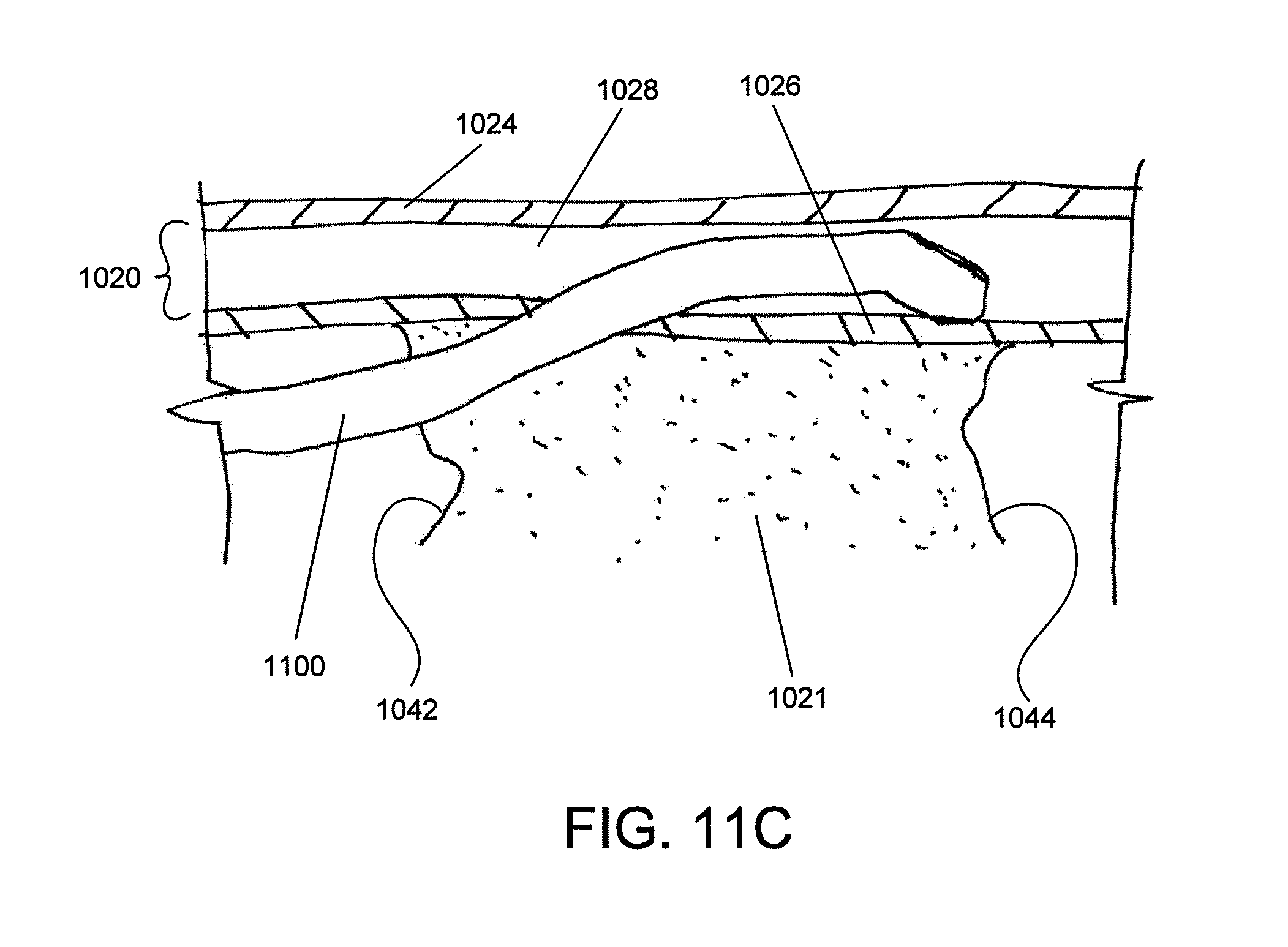
FIG. 11A shows an exemplary occluded vessel. FIG. 11B shows an occlusion-crossing catheter that has extended into the subintimal layers of the occluded vessel of FIG. 11A. FIG. 11C shows the occlusion crossing catheter of FIG. 11B trapped in the subintimal layer.
FIGS. 12A-12D show use of a stylet similar to the stylet of FIG. 1A to guide a catheter from the subintimal layer back into the true lumen. FIG. 12A shows the stylet pointing out of the catheter. FIG. 12B shows the stylet piercing through the vessel wall. FIG. 12C shows the catheter reentering the true lumen over the stylet. FIG. 12D shows the catheter reoriented within the true lumen.
FIGS. 13A-13C show use of a stylet similar to the stylet of FIG. 4A to guide a catheter from the subintimal layer back into the true lumen. FIG. 13A shows the stylet piercing the vessel wall. FIG. 13B shows the catheter reentering the true lumen over the stylet. FIG. 13C shows the catheter reoriented within the true lumen.
FIGS. 14A-14D shows use of a stylet similar to the stylet of FIG. 6 to guide a catheter from the subintimal layer back into the true lumen. FIG. 14A shows the stylet within the catheter. FIG. 14B shows the stylet piercing the wall. FIG. 14C shows the catheter reentering the true lumen over the stylet. FIG. 14D shows the stylet straightening the catheter to reorient it within the true lumen.
DETAILED DESCRIPTION
Referring to FIG. 11A, an occluded vessel 1000 includes a lumen 1022 (or "true lumen") with an occlusion 1021 and an arterial wall 1020. The arterial wall 1020 can include an innermost intimal layer 1026, which can include the endothelium, the subendothelial layer, and the internal elastic lamina. A relatively soft medial layer 1028 (also called the "subintimal space") surrounds the intimal layer 1026, which is then surrounded by an advential layer 1024. The proximal and distal caps 1042, 1044 of the occlusion are generally very hard relative to the rest of the occlusion. As a result, when a guidewire or occlusion-crossing device hits one of the caps 1042, 1044, it can often end up deflecting off of the cap 1042, 1044 and extending through the intimal layer 1026 and into the relatively soft medial layer 1028. For example, referring to FIG. 11B, an occlusion-crossing device 1100 has extended into the subintimal space within the medial layer 1028, which can define a "false lumen." As shown in FIG. 11C, the occlusion-crossing device 1100 can then get trapped in the subintimal space outside the true lumen 1022.
Stylets are described herein that can be used to assist in occlusion-crossing within a blocked vessel. For example, in some embodiments, the stylets described herein can redirect occlusion-crossing devices back into the true lumen of a vessel. In addition or alternatively, the stylets described herein can straighten and/or deflect an occlusion-crossing device to orient the device as needed.
In general, any of the stylets described herein can have a deflection region at the distal end thereof to provide directionality and steerability of the catheter. The deflection region can, for example, be imparted by a pre-shaped curve that matches an inner lumen of a catheter. The deflection region can also be imparted by an s-shaped curve at the distal tip of the stylet that helps orient and direct the stylet back into the true lumen of a vessel. In some embodiments, the deflection region can have a flattened profile to provide stability during piercing of the vessel wall into the true lumen.
Any of the stylets described herein can further be designed to include both flexible and stiff portions along the longitudinal axis to aid both in conforming the stylet to a catheter in which it is inserted and in providing the necessary stiffness to puncture a vessel wall. The stylets can include a proximal portion, a middle flexible portion, and a distal stiff portion. The middle flexible portion can be flexible enough to conform to a curve of a catheter in which the stylet is inserted while the distal stiff section can be stiff enough to provide a piercing force to guide the stylet into a true lumen of a vessel.
The stylets described herein can include an inner flexible body and an outer stiff tube. The flexible body and outer stiff tube can be moved axially relative to one another to provide the desired stiffness or flexibility for the stylet, e.g., to provide flexibility to extend around a pre-set curve in a catheter or to provide stiffness to straighten the pre-set curve. In other embodiments, the inner body can be stiff while the outer tube can be flexible.
Furthermore, the stylets described herein can include a coiled member attached to the distal tip to provide protection for the tip when in the extended configuration and allow for exposure of the tip when compressed.
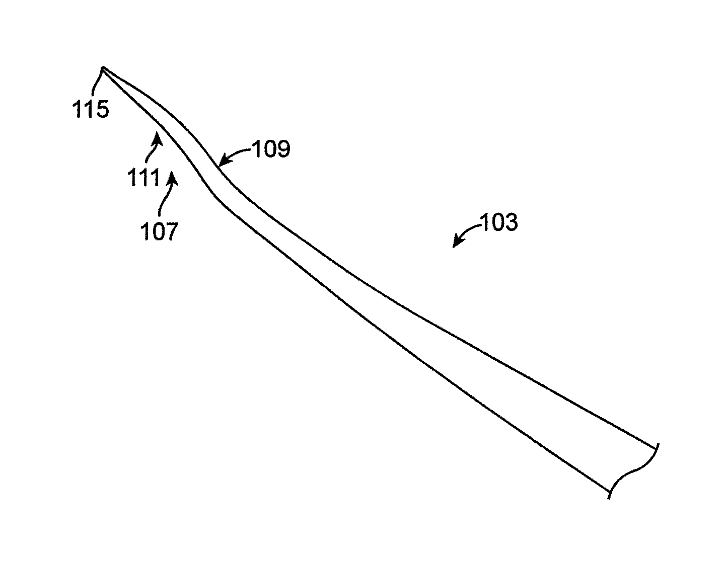
Referring to FIGS. 1A through 2C, an exemplary directional re-entry stylet 100 includes a proximal portion 101, a middle curved portion 102, and a distal pointed end 103.
The proximal portion 101 can be a wire, such as a stainless steel wire. The wire can be chosen to have a stiffness that corresponds to the required amount of pushability and column support needed for the particular wire diameter used. The proximal portion 101 can further have a substantially round cross-section. The proximal portion 101 can be approximately 0.010 to 0.035 inches in diameter, such as approximately 0.015 inches in diameter.
The curved middle portion 102 can have a pre-set curve 105 that is flexible enough to follow the contours of lumen of a catheter but stiff enough to orient its curved shape to align with a bent section of an the catheter. For example, referring to FIG. 2B, the pre-set curve 105 can form an angle .alpha. of between 120 degrees and 180 degrees, such as between about 130 degrees and 170 degrees, for example approximately 150 degrees. The pre-set curve can advantageously ensure that the stylet 100 aligns properly with the catheter in which it is inserted, thereby allowing the catheter to maintain its curved form and ensuring proper steering of the catheter.
Further, in other embodiments, the pre-set curve 105 can be stiff enough to change the deflection region of the catheter in which it is inserted. Thus, for example, the pre-set curve 105 could force the catheter into a set angle of between 120 degrees and 180 degrees, such as between about 130 degrees and 170 degrees, such as 150 degrees. In some embodiments, rather than having a pre-set curve, the curved middle portion 102 can have a flexible portion, such as a necked section or a coiled section, to allow the middle portion 102 to flexibly conform to the shape of a catheter in which it is inserted.
The curved middle portion 102 can be formed of a wire, such as a nitinol wire. The curved middle portion can further have a substantially round cross-section. The curved middle portion 102 can have a diameter of approximately 0.008 inches to 0.015 inches, such as approximately 0.012 inches in diameter. In some embodiments, the middle portion 102 is formed separately from the proximal portion 101 and connected through a junction 106, such as a hypotube joint (see FIG. 2C) or a laser welded sleeve. In other embodiments, the middle portion 102 and proximal portion 101 can be formed of a single piece of material, such as a single wire.
The pointed distal end 103 can include an s-shaped curve 107 (see FIGS. 1B and 2B), i.e., include two opposing curves 109 and 111 along the longitudinal axis. Referring to FIG. 2B, the proximal-most curve 109 of the s-shaped curve 107 can have an angle .beta. of between approximately 90.degree. to 180.degree., such as between about 120.degree. to 160.degree., such as 150.degree., while the distal-most curve 111 of the s-shaped curved 107 can have an angle .theta. of between approximately 90.degree. to 180.degree., such as 120.degree. to 160.degree., such as 150.degree.. The s-curve 107 can be oriented such that the distal end 103 points in approximately the same direction as the end of the catheter, as set by the pre-set curve 105. That is, referring to FIG. 2B, the angle .alpha. can be oriented in approximately the same direction as the angle .theta. while the angle .beta. can be aligned in substantially the opposite direction. Angles .beta. and .theta. can be approximately equal to one another. Further, having the distal end 103 point in the same direction as the distal end of the catheter (set by the jog in the catheter) advantageously provides more of an angle for re-entry into a true lumen. Finally, the alignment of the angle .alpha. with the angle .theta. also advantageously provides an indication as to the orientation of the stylet.
The distal tip 115 (between the distal-most point and the distal curve 111) can be less than about 3 mm, such as between about 1-2 mm. Further, the stylet 100 itself can be about 150 cm-300 cm in length, such as 175 cm to 200 cm, such as approximately 180 cm in length. Thus, the distal tip 115 can comprises less than 1%, such as less than 0.5% of the total length of the stylet 100. The short length of the distal tip 115 relative to the length of the entire stylet 100 advantageously provides that the stylet will advance only partially through the vessel wall and back into the true lumen during reentry (i.e., to avoid puncturing the opposite wall of the vessel).
In other embodiments, rather than having an s-shaped curve 107, the pointed distal end 103 can include a J-shaped curve, i.e. a hook, that can be used to force the stylet 100 (and thus the catheter in which it is inserted) back towards a true lumen.
The pointed distal end 103 can further included a flattened portion, i.e., a portion in which the otherwise round cross-section has been flattened to include two substantially parallel and flat surfaces, e.g., such that a cross-section of the flattened portion is substantially oblong. As shown in FIG. 1B, the s-curve 107 can be located within the flattened portion such that the shape of the "s" is formed on the flattened surface. This flattened portion can advantageously help to hold the pre-set curve as it is forced against tissue. The flattened portion can also advantageously provide rigidity as the tip of the stylet is forced into tissue.
Further, the pointed distal end 103 can be tapered from the proximal end to the distal end. For example, the distal end can be 0.012 inches in diameter and can taper down to a tip 115 of approximately 0.005 inches in diameter. The tip 115 of the pointed distal end 103 can be sharp, i.e., can be configured to penetrate tissue, such as subintimal layers of a blood vessel. The taper can advantageously provide smooth dilation or entry into a vessel wall or occlusion.
Referring to FIGS. 12A-12D, in one embodiment, a stylet 100 can be used as a re-entry tool for an occlusion-crossing catheter 1100 that has exited the true lumen 1022 and entered the subintimal layer (e.g., medial layer 1028). The stylet 100 can be placed through a guidewire channel of a catheter 1100. The catheter 1100 can have a fixed bend 1114, which can be rotated to point towards the true lumen 1022. As shown in FIG. 12A, the stylet 100 can be threaded through the catheter 1100 such that the curved middle portion 102 aligns with the bend 1114 in the catheter 1100 and such that the tip 115 points out the distal end of the catheter. Because the angle of the curved middle portion 102 is pointed in the same direction as the distal-most curve of the s-shaped curve, and because the fixed bend 1114 has been oriented towards the true lumen 1022, the distal tip 115 will also point towards the true lumen 1022. Further, referring to FIG. 12B, because the curved middle portion 102 has a pre-set curve, the curve will hold the stylet's orientation as it is advanced. Thus, as the stylet is advanced, the distal tip 115 will curve even more sharply towards the true lumen 1022 and pierce back through the tissue of the vessel wall 1020 at a steep angle (e.g. at an angle of between approximately 60 and 90 degrees relative to the wall). Referring to FIG. 12C, the catheter 1100 can then be advanced over the stylet 100 back into the true lumen 1022. As shown in FIG. 12D, to reorient the catheter 1100 towards down the axis of the lumen 1022, the catheter can be rotated approximately 180 degrees to point the fixed bend 1114 down the lumen 1022. In some embodiments, this process can be used to pass entirely by an occlusion (as shown in FIGS. 12A-12D). In other embodiments, the stylet 100 can direct the catheter 1100 back into the occlusion at a point between the proximal 1042 and distal 1044 caps of the occlusion 1021, and then the catheter 1100 can be used to finish crossing through the lesion, such as will a rotating drill feature on the distal end of the catheter.
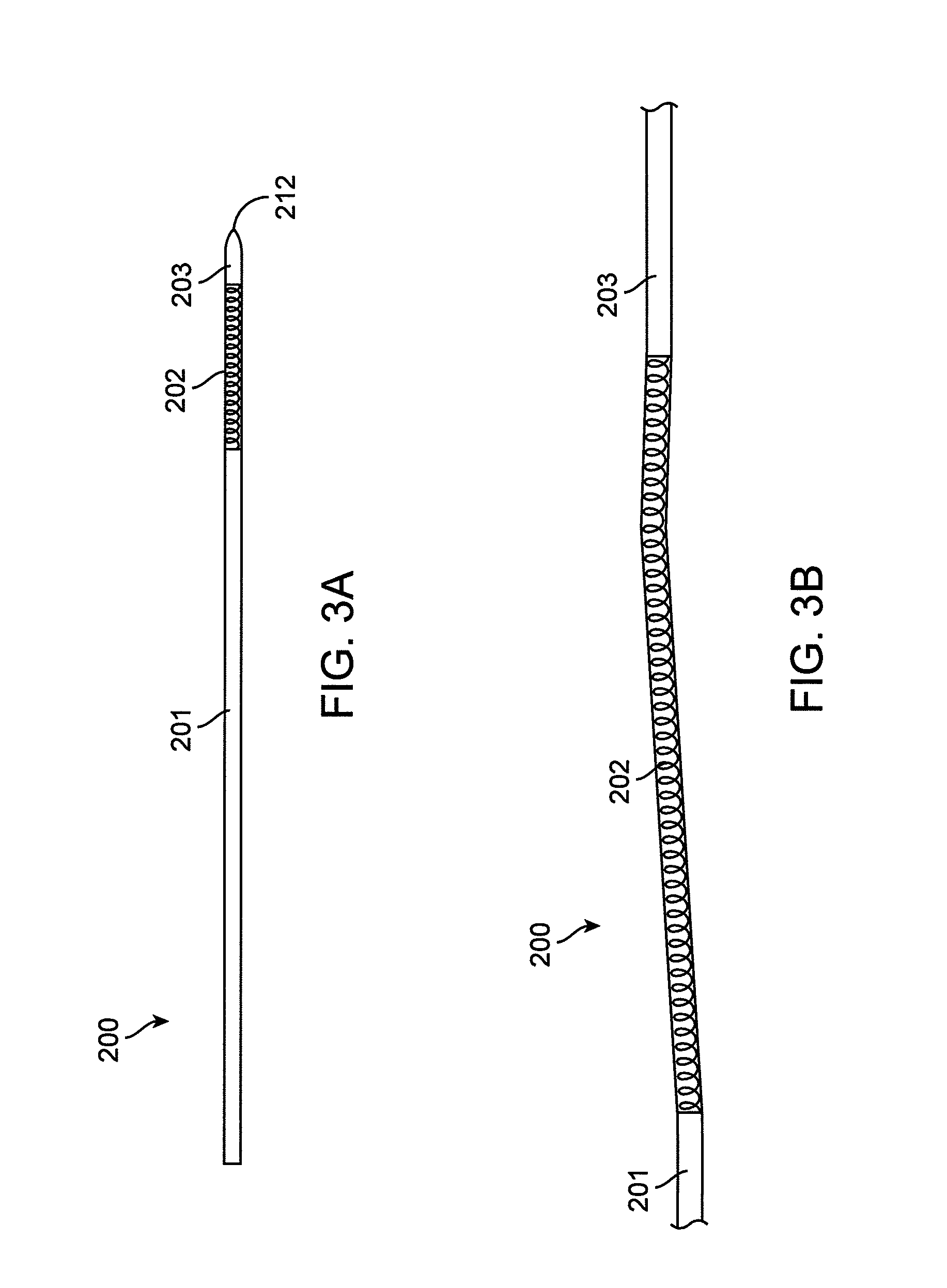
Referring to FIGS. 3A-3B, an aligning re-entry stylet 200 includes a proximal portion 201, a middle flexible portion 202, and a distal stiff portion 203.
The proximal portion 201 can be a wire, such as a stainless steel wire. The wire can be stiff enough to provide pushability through a catheter. The proximal portion 201 can be approximately 0.010 to 0.038 inches in diameter, such as approximately 0.015 inches in diameter.
The middle flexible portion 202 is configured to be flexible so as to conform to the shape of a catheter in which it is inserted. In one embodiment, the flexible portion 202 is a coil, such as a coil of wire. The coil can have an outer diameter of 0.010 to 0.038 inches, such as approximately 0.014 inches and an inner diameter of 0.005 to 0.010 inches, such as approximately 0.008 inches. The coil can be made, for example, of stainless steel. The wire forming the coil can have a diameter of 0.001 to 0.005 inches, such as approximately 0.003 inches. In another embodiment, the middle flexible portion 202 could be a necked portion in a wire. In another embodiment, the middle flexible portion 202 can be a separate flexible material, such as a plastic. In another embodiment, the middle flexible portion 202 can be a hypotube that has been cut, such as laser cut, into a flexible spiral or plurality of rings along a spine.
The proximal stiff portion 203 can be stiff enough to straighten a prebent catheter in which it is inserted. For example, the proximal stiff portion can be made of a stainless steel wire. The wire can have a diameter, for example, of 0.010 to 0.038 inches, such as approximately 0.015 inches. The distal portion 203 can further include a sharp tip 212, such as a needle-like or pointed end. In some embodiments, the sharp tip 212 can be angled to assist in re-entry.
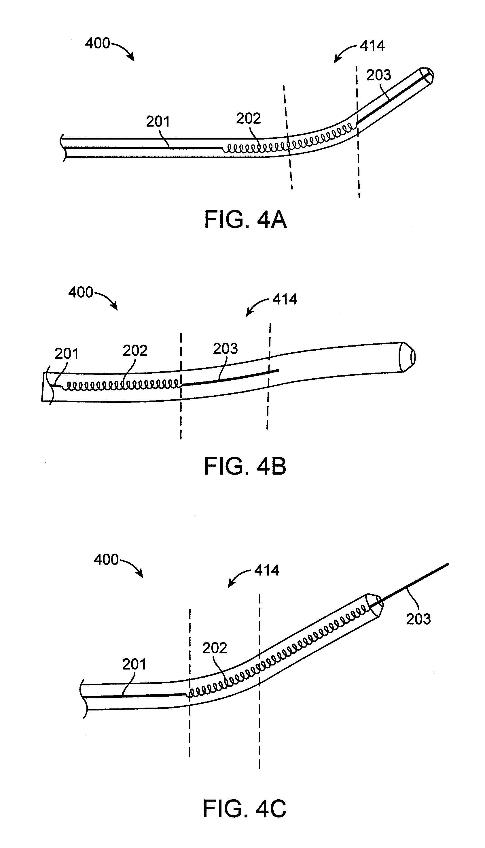
The flexible portion 202 can have a length such that the flexible portion can align with a pre-set curve 414 in a catheter 400 in which it is inserted both while the distal stiff portion 203 remains inside the catheter 400 (FIG. 4A) and while the distal stiff portion 203 extends distally from the distal end of the catheter 400 (FIG. 4C).
In use, referring to FIGS. 4A-4C, the stylet 200 can be inserted into a catheter, such as a catheter 400 having a pre-bent curve 414. As shown in FIG. 4A, the stylet 200 can be inserted such that the flexible portion 202 aligns with the pre-bent curve 414 while the distal portion 203 remains inside the catheter. This alignment can advantageously provide little interference with the catheter as the catheter is used under normal conditions.
The stylet 200 can also be inserted such that the distal stiff portion 203 aligns with the pre-bent curve 414, thereby straightening the curve, as shown in FIG. 4B. This alignment can advantageously make directly entry into an occlusion easier, i.e., placing force on a straightened catheter, from within the true lumen, can provide a straight trajectory into the occlusion.
Finally, as shown in FIG. 4C, the stylet 200 can be inserted such that the flexible portion 202 aligns with the pre-bent curve 414 while the distal portion 203 extends out of the distal end of the catheter 400. This alignment can advantageously assist in re-entry from a false lumen to a true lumen, i.e., the curve of the catheter 400 can be turned towards the true lumen, and the distal end 203 of the stylet 200 can be used to pierce the vessel and guide the catheter 400 back into the true lumen. For example, FIGS. 13A-13C show a stylet 200 used as a re-entry tool for an occlusion-crossing catheter 1100 that has exited the true lumen 1022 and entered the subintimal layer (e.g., medial layer 1028). The stylet 200 can be placed through a guidewire channel of the catheter 1100. The catheter 1100 can have a fixed bend 1114, which can be rotated to point towards the true lumen 1022. As shown in FIG. 13A, the stylet 200 can be threaded through the catheter 1100 such that the flexible portion 202 aligns with the fixed bend 1114 while the distal portion extends out of the distal end of the catheter 1100. Because the fixed bend 1114 has been oriented towards true lumen 1022, the sharp distal portion 203 will also point towards the true lumen 1022, making it easy to pierce the wall 1020. Referring to FIG. 13B, the catheter 1100 can then be advanced over the stylet 200 back into the true lumen 1022. As shown in FIG. 12C, to reorient the catheter 1100 towards down the axis of the lumen 1022, the catheter can be rotated approximately 180 degrees to point the fixed bend 1114 down the lumen 1022. In some embodiments, this process can be used to pass entirely by an occlusion (as shown in FIGS. 13A-13C). In other embodiments, the stylet 200 can direct the catheter 1100 back into the occlusion at a point between the proximal 1042 and distal 1044 caps, and then the catheter 1100 can be used to finish crossing through the lesion, such as with drilling features on the catheter 1100.
Referring to FIGS. 5A-5C, a stylet 200 can be made, for example, by grinding two mandrels to a taper 510a,b (the mandrels will form the proximal and distal ends, respectively), and then placing the tapers 510a,b inside a coil 202 and connecting the coil 202 to each taper 510a,b, as shown in FIG. 5C.
Referring to FIG. 6, a stylet 300 can include an outer tube 310 and an inner elongate body 312 axially movable relative to the outer tube 310. The outer tube 310 can be stiff relative to the inner elongate body 312. The inner elongate body 312 can have a pointed or sharp distal end 303 similar to the distal end of the stylets 100, 200. The inner elongate body 312 and/or the outer tube 310 can be made of a metal, such as stainless steel or nitinol.
Further, referring to FIGS. 7A-7B, the stylet 300 can be configured to be placed within a lumen of a catheter, such as a catheter 500 having a pre-set curve 514. The outer tube 310 can be stiff relative to the pre-set curve 514 while the inner elongate body 312 can be flexible relative to the pre-set curve 514. As a result, the outer tube 310 can be used to straighten the pre-set curve 514 while the inner elongate body 312 can conform to the pre-set curve 514.
Thus, referring to FIG. 7A, the stylet 300 can be placed such that the entire stylet 300 is proximal to the pre-set curve 514. As shown in FIG. 7B, if the outer tube 310 is advanced distal to the pre-set curve 514, then the pre-set curve 514 of the catheter 500 will substantially straighten out. Such straightening can be advantageous, for example, if the catheter 500 is being used to cross a CTO from within the true lumen, as force can be applied on the CTO from substantially perpendicular to the CTO. Referring to FIG. 7D, the inner elongate body 312 can also be extended out of the distal end of the catheter while the catheter is in a straightened position to assist with crossing the CTO (e.g. such that the pointed distal end 303 can cut through the occlusion or pierce the proximal or distal cap). On the other hand, as shown in FIG. 7C, if only the inner elongate body 312 is advanced distal to the pre-set curve 514, then the pre-set curve 514 can maintain its shape while the pointed distal end 303 can be advanced out of the catheter 500. This configuration can be advantageous, for example, for re-entry form a false lumen to a true lumen, i.e. the curve 514 of the catheter 514 can be turned towards the true lumen, and the pointed distal end 303 of the inner elongate body 312 can be used to pierce the vessel and guide the catheter 500 back into the true lumen.
FIGS. 14A-14D show a stylet 300 used as a re-entry tool for an occlusion-crossing catheter 1100 that has exited the true lumen 1022 and entered the subintimal layer (e.g., medial layer 1028). As shown in FIG. 14A, the stylet 300 can be placed through a guidewire channel of the catheter 1100. The catheter 1100 can have a fixed bend 1114, which can be rotated to point towards the true lumen 1022. Referring to FIG. 14B, the inner elongate body 312 can then be extended towards the true lumen 1022. Because the fixed bend 1114 has been oriented towards the true lumen 1022, the pointed distal end 303 will also point towards the true lumen 1022, thereby allowing it to pierce the vessel wall 1020 as it is extended. Referring to FIG. 14C, the catheter 1100 can then be advanced over the stylet 300 back into the true lumen 1022. As shown in FIG. 12D, the outer tube 310 can then be extended within the catheter 1100 such that it straightens the fixed bend 1114. Such straightening of the fixed bend 1114 will point the catheter 1100 more directly down the true lumen 1022. In some embodiments, this process can be used to pass entirely by an occlusion (as shown in FIGS. 14A-14D). In other embodiments, the stylet 300 can direct the catheter 1100 back into the occlusion at a point between the proximal 1012 and distal 1044 caps, and then the catheter 1100 can be used to finish crossing through the lesion.
In some embodiments, the inner elongate body 312 can have a pre-set curve that substantially matches the pre-set curve 514 of the catheter 500. For example, the inner elongate body 312 can be made of a shape memory material, such as nitinol, to set the curve. Having this matched curve can advantageously help with re-entry into the true lumen. That is, if the user steers the directionality of the catheter 500 towards the true lumen, then when the curved inner elongate body 312 exits, it will curve and be directed towards the true lumen even more than the catheter itself, helping to avoid deflection off of the vessel wall.
In general, a sharp distal tip of any of the stylets described herein may be protected or covered until deployment into tissue. For example, a spring loaded sheath or housing can be pushed distally along the long axis of the tip to expose the sharp tip. For example, as shown in FIGS. 10A and 10B, a stylet 900 can include a spring-loaded mechanism 902 on the distal end of a stylet body 910. Thus, a coiled member 904 can be configured to extend over the tip 906 of the stylet, which can be sharp and/or tapered. Referring to FIG. 10A, in the passive mode, i.e. before contacting tissue, the coiled member 904 can cover the tapered or sharp end of the stylet so that the end is atraumatic in non-targeted areas. Once the location of re-entry is reached, the tip 906 can be advanced into the tissue, thus activating the spring mechanism (shown in FIG. 10B) as the coil compresses and exposes the penetrating tip 906.
The length of exposed tip 906 can be controlled by placing the coiled member 904 in the desired location along the stylet body 910. Accordingly, the initial length of the tip 906 that is exposed through the vessel wall or occlusion can be limited by the coiled member 904, advantageously avoiding over-puncturing and possibly hitting the opposing vessel wall. Further, the pitch of the coiled member 904 can be chosen based upon the desired spring force required to penetrate or puncture the tissue, such as based upon the type or thickness of the tissue. Once the tip has been pushed fully through, the coiled member 904 can act as a temporary stop, providing tactile feedback for the user and allowing the user to adjust the angle or orientation of the stylet tip. Additional force can then be placed on the stylet 900 to push the coiled member 904 through. Once the proximal end of the coiled member 904 is fully advanced through the tissue, the coiled member can relax, allowing the stylet 900 to be in passive mode again as it traverses through the vessel.
Although a coiled member 904 is shown in FIGS. 10A and 10B, other spring loaded mechanisms 902 are possible. Advantageously, spring loaded mechanisms 902 on the stylet can help control depth of penetration and also provide a safer method of controlling re-entry. The spring-loaded mechanism 902 can be used with a traditional stylet or with any of the stylets described herein.
Referring to FIG. 8, a handle 800 can be used to steer any of the stylets described herein. The handle 800 can include a locking mechanism to lock it onto the proximal end of the device, such as a luer fitting. In one embodiment, the handle 800 can have predefined positions that align the stylet appropriately with the catheter. For example, if the handle 800 is used with the stylet 200, the handle can lock the stylet 200 in a first position where the stylet 300 is proximal of the bend in the catheter, thereby allowing the main body of the catheter to have extra support. The handle can also lock the stylet 200 in a second position where the distal stiff section of the stylet 200 is in the prebent section of the catheter, thereby straightening the catheter. Finally, the handle 800 can lock the stylet 200 in a third position where the distal part of the stylet 200 sticks out of the distal tip of the catheter, thereby enabling re-entry into the true lumen. The handle 800 can include similar predefined positions when used with the other stylets described in here.
Any of the embodiments of stylets herein can include an anchoring mechanism on or near the distal tip. For example, the distal end can include a hook 991 as shown in FIG. 9A or a drill tip 993 as shown in FIG. 9B. The anchoring mechanism can anchor the stylet in a particular location where re-entry is desired, i.e., can prevent proximal movement, and then can be dislodged as the stylet is advanced distally past the location.
Any of the stylets described herein can include a marker, such as a radiopaque marker, to help identify the location of the stylet in situ with imaging. For example, referring to the stylet 100 of FIGS. 1A-2C, the connector 106 between the proximal portion 101 and the middle portion 102 can form the radiopaque marker. In some embodiments, a radiopaque coating, such as platinum, can be applied to portions of the stylet 100.
Any of the stylets described herein can include a torquer configured to be tightened onto the stylet for rotational control. In some embodiments, the torquer can be aligned with a particular angle in the stylet. For example, the torquer can align with one or more of the angles of the s-curve 107 of the stylet 100.
Any of the stylets described herein can be sized and configured to fit within a guidewire channel of a catheter, such as through a guidewire channel of an occlusion-crossing device. Such exemplary occlusion-crossing devices are described in co-pending patent applications: U.S. patent application Ser. No. 12/829,267, titled "CATHETER-BASED OFF-AXIS OPTICAL COHERENCE TOMOGRAPHY IMAGING SYSTEM," filed Jul. 1, 2010, Publication No. US-2010-0021926-A1; U.S. patent application Ser. No. 13/433,049, titled "OCCLUSION-CROSSING DEVICES, IMAGING, AND ATHERECTOMY DEVICES," filed Mar. 28, 2012, Publication No. US-2012-0253186-A1; International Patent Application titled "OCCLUSION-CROSSING DEVICES," filed herewith; and International Patent Application titled "CHRONIC TOTAL OCCLUSION CROSSING DEVICES WITH IMAGING," filed herewith, all of which are incorporated by reference in their entireties.
Further, any of the stylets and/or catheters described herein can be oriented, directed, or steered using image guidance, such as optical coherence tomography, ultrasound, radiofrequency imaging, or fluoroscopy.
Additional details pertinent to the present invention, including materials and manufacturing techniques, may be employed as within the level of those with skill in the relevant art. The same may hold true with respect to method-based aspects of the invention in terms of additional acts commonly or logically employed. Also, it is contemplated that any optional feature of the inventive variations described may be set forth and claimed independently, or in combination with any one or more of the features described herein. Likewise, reference to a singular item, includes the possibility that there are a plurality of the same items present. More specifically, as used herein and in the appended claims, the singular forms "a," "and," "said," and "the" include plural referents unless the context clearly dictates otherwise. It is further noted that the claims may be drafted to exclude any optional element. As such, this statement is intended to serve as antecedent basis for use of such exclusive terminology as "solely," "only" and the like in connection with the recitation of claim elements, or use of a "negative" limitation. Unless defined otherwise herein, all technical and scientific terms used herein have the same meaning as commonly understood by one of ordinary skill in the art to which this invention belongs. The breadth of the present invention is not to be limited by the subject specification, but rather only by the plain meaning of the claim terms employed.
When a feature or element is herein referred to as being "on" another feature or element, it can be directly on the other feature or element or intervening features and/or elements may also be present. In contrast, when a feature or element is referred to as being "directly on" another feature or element, there are no intervening features or elements present. It will also be understood that, when a feature or element is referred to as being "connected", "attached" or "coupled" to another feature or element, it can be directly connected, attached or coupled to the other feature or element or intervening features or elements may be present. In contrast, when a feature or element is referred to as being "directly connected", "directly attached" or "directly coupled" to another feature or element, there are no intervening features or elements present. Although described or shown with respect to one embodiment, the features and elements so described or shown can apply to other embodiments. It will also be appreciated by those of skill in the art that references to a structure or feature that is disposed "adjacent" another feature may have portions that overlap or underlie the adjacent feature.
Terminology used herein is for the purpose of describing particular embodiments only and is not intended to be limiting of the invention. For example, as used herein, the singular forms "a", "an" and "the" are intended to include the plural forms as well, unless the context clearly indicates otherwise. It will be further understood that the terms "comprises" and/or "comprising," when used in this specification, specify the presence of stated features, steps, operations, elements, and/or components, but do not preclude the presence or addition of one or more other features, steps, operations, elements, components, and/or groups thereof. As used herein, the term "and/or" includes any and all combinations of one or more of the associated listed items and may be abbreviated as "/".
Spatially relative terms, such as "under", "below", "lower", "over", "upper" and the like, may be used herein for ease of description to describe one element or feature's relationship to another element(s) or feature(s) as illustrated in the figures. It will be understood that the spatially relative terms are intended to encompass different orientations of the device in use or operation in addition to the orientation depicted in the figures. For example, if a device in the figures is inverted, elements described as "under" or "beneath" other elements or features would then be oriented "over" the other elements or features. Thus, the exemplary term "under" can encompass both an orientation of over and under. The device may be otherwise oriented (rotated 90 degrees or at other orientations) and the spatially relative descriptors used herein interpreted accordingly. Similarly, the terms "upwardly", "downwardly", "vertical", "horizontal" and the like are used herein for the purpose of explanation only unless specifically indicated otherwise.
Although the terms "first" and "second" may be used herein to describe various features/elements, these features/elements should not be limited by these terms, unless the context indicates otherwise. These terms may be used to distinguish one feature/element from another feature/element. Thus, a first feature/element discussed below could be termed a second feature/element, and similarly, a second feature/element discussed below could be termed a first feature/element without departing from the teachings of the present invention.
As used herein in the specification and claims, including as used in the examples and unless otherwise expressly specified, all numbers may be read as if prefaced by the word "about" or "approximately," even if the term does not expressly appear. The phrase "about" or "approximately" may be used when describing magnitude and/or position to indicate that the value and/or position described is within a reasonable expected range of values and/or positions. For example, a numeric value may have a value that is +/-0.1% of the stated value (or range of values), +/-1% of the stated value (or range of values), +/-2% of the stated value (or range of values), +/-5% of the stated value (or range of values), +/-10% of the stated value (or range of values), etc. Any numerical range recited herein is intended to include all sub-ranges subsumed therein.
* * * * *
D00000
D00001
D00002
D00003
D00004
D00005
D00006
D00007
D00008
D00009
D00010
D00011
D00012

D00013

D00014

D00015
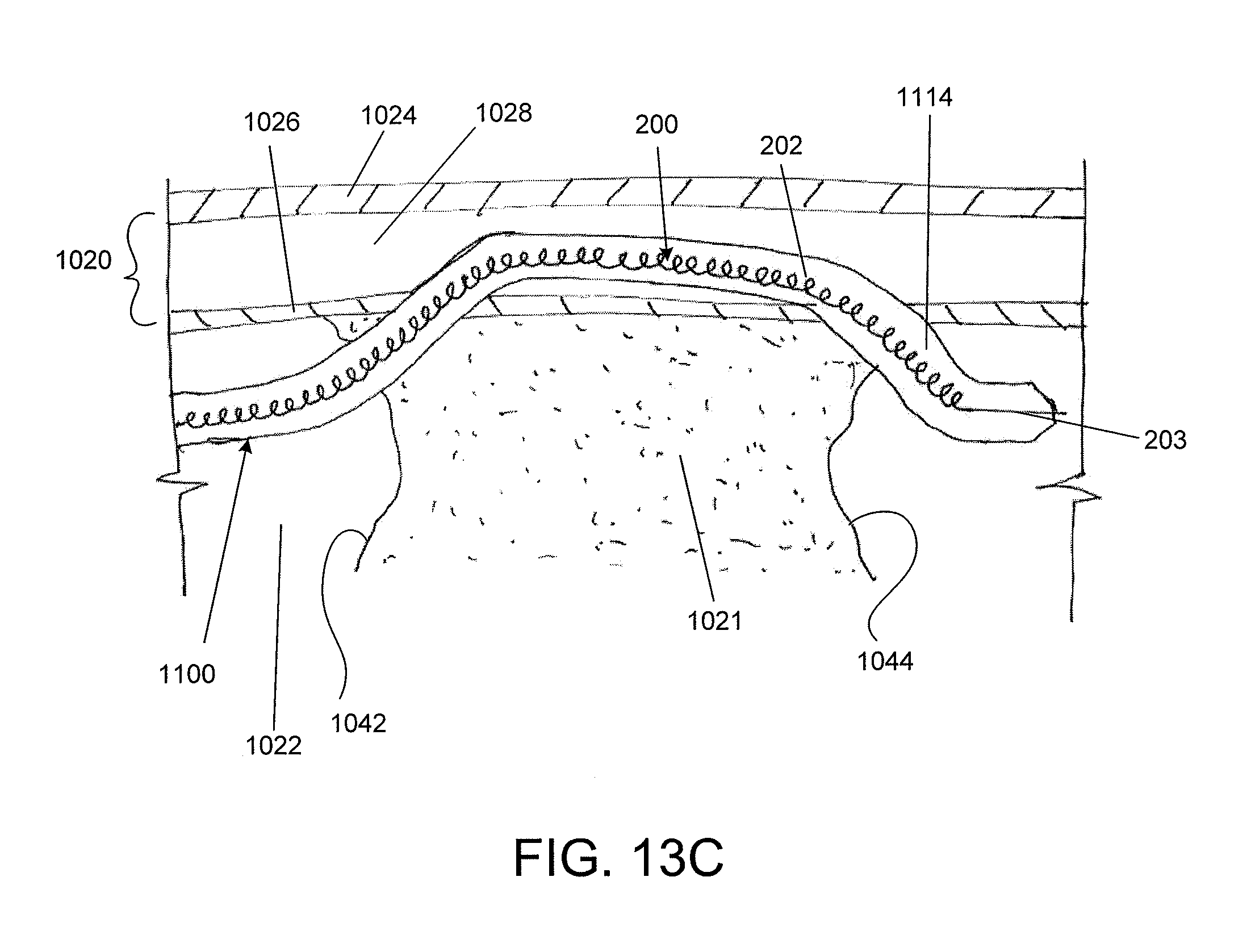
D00016

D00017
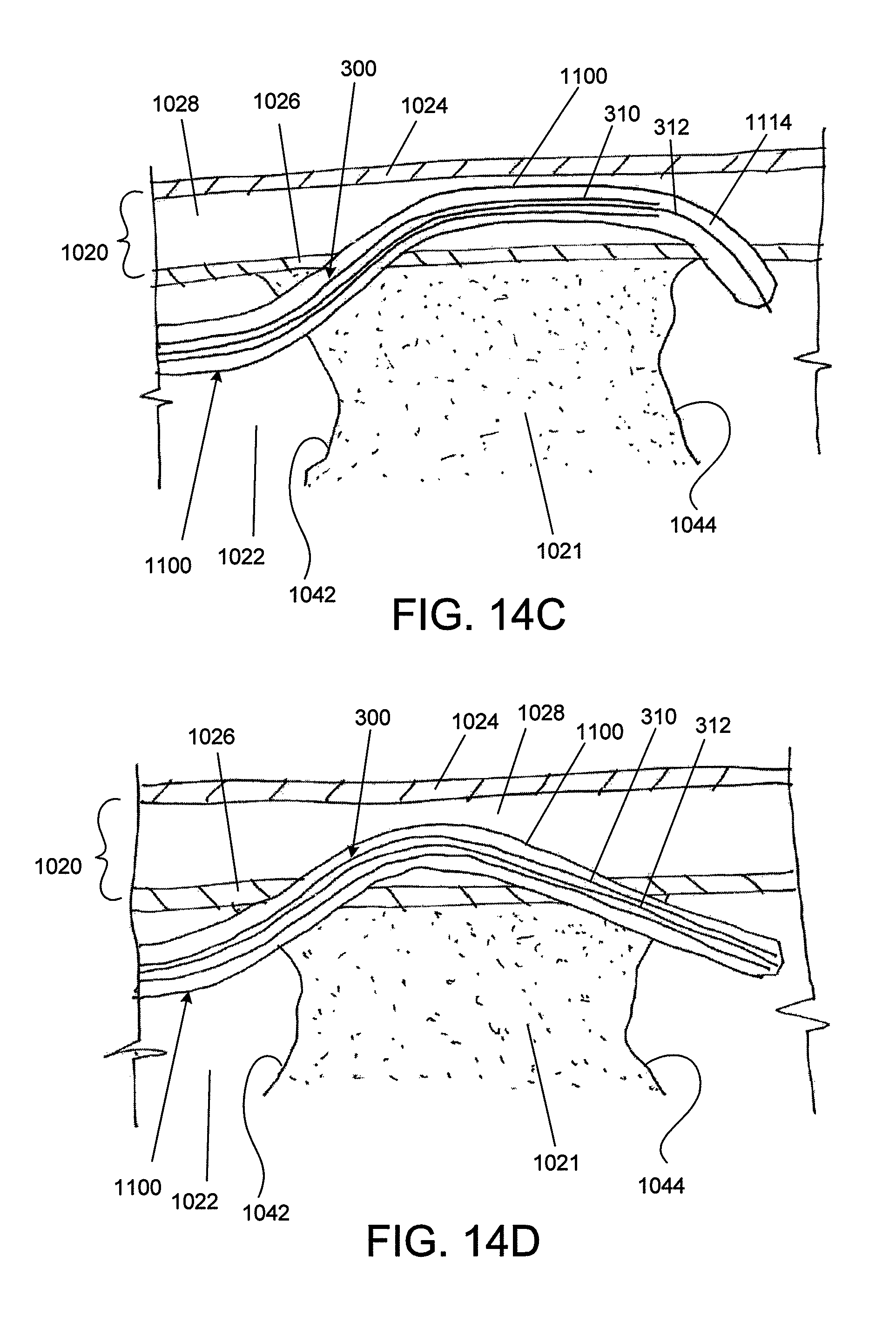
XML
uspto.report is an independent third-party trademark research tool that is not affiliated, endorsed, or sponsored by the United States Patent and Trademark Office (USPTO) or any other governmental organization. The information provided by uspto.report is based on publicly available data at the time of writing and is intended for informational purposes only.
While we strive to provide accurate and up-to-date information, we do not guarantee the accuracy, completeness, reliability, or suitability of the information displayed on this site. The use of this site is at your own risk. Any reliance you place on such information is therefore strictly at your own risk.
All official trademark data, including owner information, should be verified by visiting the official USPTO website at www.uspto.gov. This site is not intended to replace professional legal advice and should not be used as a substitute for consulting with a legal professional who is knowledgeable about trademark law.