Adjustable seat assembly
O'Bannon , et al.
U.S. patent number 10,328,823 [Application Number 14/560,436] was granted by the patent office on 2019-06-25 for adjustable seat assembly. This patent grant is currently assigned to Lear Corporation. The grantee listed for this patent is Lear Corporation. Invention is credited to Ashford Allen Galbreath, Samuel R. Hanlon, Karl Henn, Terry O'Bannon, Gerald Patrick, Michelle A. Pereny.


| United States Patent | 10,328,823 |
| O'Bannon , et al. | June 25, 2019 |
| **Please see images for: ( Certificate of Correction ) ** |
Adjustable seat assembly
Abstract
A seat assembly is provided with a translatable seat cushion, a pivotal seat back, and a head restraint adapted to be mounted for translation adjacent the seat back. An actuator is operably connected to at least one of the seat cushion and the seat back for adjustment of a plurality of settings of the seat assembly. A controller is in electrical communication with the actuator and is configured to receive input indicative of occupant anthropometry data, current physical condition and/or activity level, compare the input with predetermined data ranges, and adjust at least one of the plurality of settings of the actuator to a predetermined setting based on the predetermined range. A computer-program product is programmed for automatically adjusting a seat assembly. A method for adjusting a seat assembly receives anthropometry data for an occupant.
| Inventors: | O'Bannon; Terry (Royal Oak, MI), Pereny; Michelle A. (Farmington Hills, MI), Hanlon; Samuel R. (Livonia, MI), Galbreath; Ashford Allen (Troy, MI), Patrick; Gerald (Shelby Township, MI), Henn; Karl (New Hudson, MI) | ||||||||||
|---|---|---|---|---|---|---|---|---|---|---|---|
| Applicant: |
|
||||||||||
| Assignee: | Lear Corporation (Southfield,
MI) |
||||||||||
| Family ID: | 54768900 | ||||||||||
| Appl. No.: | 14/560,436 | ||||||||||
| Filed: | December 4, 2014 |
Prior Publication Data
| Document Identifier | Publication Date | |
|---|---|---|
| US 20150352979 A1 | Dec 10, 2015 | |
Related U.S. Patent Documents
| Application Number | Filing Date | Patent Number | Issue Date | ||
|---|---|---|---|---|---|
| 62009585 | Jun 9, 2014 | ||||
| Current U.S. Class: | 1/1 |
| Current CPC Class: | B60N 2/806 (20180201); B60N 2/0248 (20130101); B60N 2/002 (20130101); B60N 2/06 (20130101); B60N 2/16 (20130101); B60N 2002/0268 (20130101) |
| Current International Class: | B60N 2/00 (20060101); B60N 2/02 (20060101); B60N 2/806 (20180101); B60N 2/16 (20060101) |
References Cited [Referenced By]
U.S. Patent Documents
| 4477874 | October 1984 | Ikuta et al. |
| 4679855 | July 1987 | Hattori et al. |
| 5019759 | May 1991 | Takemura |
| 5707109 | January 1998 | Massara et al. |
| 5758924 | June 1998 | Vishey |
| 5822707 | October 1998 | Breed |
| 5967608 | October 1999 | Van Sickle |
| 5975633 | November 1999 | Walk et al. |
| 6088642 | July 2000 | Finkelstein et al. |
| 6088643 | July 2000 | Long et al. |
| 6129419 | October 2000 | Neale |
| 6203105 | March 2001 | Rhodes, Jr. |
| 6220667 | April 2001 | Wagner |
| 6227563 | May 2001 | Talisman |
| 6273810 | August 2001 | Rhodes, Jr. et al. |
| 6289538 | September 2001 | Fidge |
| 6392550 | May 2002 | Najor |
| 6398303 | June 2002 | Herrmann et al. |
| 6578916 | June 2003 | Longhi et al. |
| 6592533 | July 2003 | Yonekawa et al. |
| 6682059 | January 2004 | Daniels et al. |
| 7131697 | November 2006 | Beermann et al. |
| 7152920 | December 2006 | Sugiyama et al. |
| 7537286 | May 2009 | Walker et al. |
| 7663502 | February 2010 | Breed |
| 7797771 | September 2010 | Bossen |
| 7865375 | January 2011 | Lancaster et al. |
| 7917264 | March 2011 | Hozumi et al. |
| 7967379 | June 2011 | Walters et al. |
| 8054203 | November 2011 | Breed et al. |
| 8251447 | August 2012 | Fujita et al. |
| 8348339 | January 2013 | Onuma et al. |
| 8474908 | July 2013 | Petzel et al. |
| 8596716 | December 2013 | Caruso |
| 8616654 | December 2013 | Zenk et al. |
| 8690249 | April 2014 | Kang et al. |
| 8775018 | July 2014 | Uenuma et al. |
| 8872640 | October 2014 | Horseman |
| 8931837 | January 2015 | Vernon |
| 8958955 | February 2015 | Hotary et al. |
| 9049937 | June 2015 | Walker |
| 9381840 | July 2016 | Tobata et al. |
| 2002/0056709 | May 2002 | Burt |
| 2002/0089220 | July 2002 | Achleitner et al. |
| 2002/0096915 | July 2002 | Haupt et al. |
| 2002/0167486 | November 2002 | Tan et al. |
| 2003/0023363 | January 2003 | Katz et al. |
| 2003/0080699 | May 2003 | Rumney |
| 2003/0226399 | December 2003 | Clingerman et al. |
| 2005/0067868 | March 2005 | Kern et al. |
| 2006/0061315 | March 2006 | Schmidt et al. |
| 2006/0103193 | May 2006 | Kramer |
| 2006/0290175 | December 2006 | Hartwich |
| 2007/0106188 | May 2007 | Walker |
| 2008/0009989 | January 2008 | Kim et al. |
| 2008/0116730 | May 2008 | Connolly et al. |
| 2008/0255731 | October 2008 | Mita et al. |
| 2008/0267460 | October 2008 | Aoki et al. |
| 2008/0277985 | November 2008 | Petzel |
| 2009/0026821 | January 2009 | Macht et al. |
| 2009/0030578 | January 2009 | Periot et al. |
| 2009/0058661 | March 2009 | Gleckler et al. |
| 2009/0088930 | April 2009 | Ohtsubo et al. |
| 2009/0099490 | April 2009 | Durt et al. |
| 2009/0107258 | April 2009 | Saitoh et al. |
| 2010/0045087 | February 2010 | Pyun et al. |
| 2010/0244504 | September 2010 | Colja et al. |
| 2010/0276973 | November 2010 | Zenk et al. |
| 2010/0283299 | November 2010 | Onuma et al. |
| 2011/0031788 | February 2011 | Kosik et al. |
| 2011/0112449 | May 2011 | Hopf et al. |
| 2011/0210590 | September 2011 | Mori et al. |
| 2012/0053794 | March 2012 | Alcazar |
| 2012/0086249 | April 2012 | Hotary |
| 2012/0096960 | April 2012 | Galbreath et al. |
| 2012/0259248 | October 2012 | Receveur |
| 2012/0283929 | November 2012 | Wakita et al. |
| 2013/0009761 | January 2013 | Horseman |
| 2013/0090816 | April 2013 | Huber |
| 2013/0166078 | June 2013 | Heger et al. |
| 2013/0175838 | July 2013 | Oshima et al. |
| 2013/0251216 | September 2013 | Smowton et al. |
| 2013/0313871 | November 2013 | Shalaby et al. |
| 2014/0163333 | June 2014 | Horseman |
| 2014/0167463 | June 2014 | Sakata et al. |
| 2014/0319895 | October 2014 | Lange-Mao et al. |
| 2014/0361590 | December 2014 | Line et al. |
| 2015/0008710 | January 2015 | Young |
| 2015/0084985 | March 2015 | Baudu |
| 2015/0097400 | April 2015 | Heys |
| 2015/0099245 | April 2015 | Bouchard et al. |
| 2015/0136146 | May 2015 | Hood et al. |
| 2015/0351692 | December 2015 | Pereny et al. |
| 2015/0352990 | December 2015 | Zouzal et al. |
| 2015/0367751 | December 2015 | Lamesch et al. |
| 2016/0101710 | April 2016 | Bonk et al. |
| 2016/0297337 | October 2016 | White et al. |
| 1087804 | Jun 1994 | CN | |||
| 1731102 | Feb 2006 | CN | |||
| 101161500 | Apr 2008 | CN | |||
| 101374695 | Feb 2009 | CN | |||
| 201329822 | Oct 2009 | CN | |||
| 101731862 | Jun 2010 | CN | |||
| 201646470 | Nov 2010 | CN | |||
| 101992708 | Mar 2011 | CN | |||
| 102015362 | Apr 2011 | CN | |||
| 102099227 | Jun 2011 | CN | |||
| 102991442 | Mar 2013 | CN | |||
| 104044495 | Sep 2014 | CN | |||
| 104252615 | Dec 2014 | CN | |||
| 19908655 | Aug 2000 | DE | |||
| 10331624 | Apr 2005 | DE | |||
| 10353020 | Jun 2005 | DE | |||
| 102005034069 | Jan 2007 | DE | |||
| 102005038289 | Mar 2007 | DE | |||
| 102006036532 | Feb 2008 | DE | |||
| 102009021532 | Nov 2010 | DE | |||
| 102011010210 | Dec 2011 | DE | |||
| 102010056568 | Jul 2012 | DE | |||
| 102012216869 | Mar 2014 | DE | |||
| 102012216178 | May 2014 | DE | |||
| 0489310 | Jun 1992 | EP | |||
| 2353928 | Aug 2011 | EP | |||
| 2353928 | Sep 2014 | EP | |||
| 2988051 | Sep 2013 | FR | |||
| 2988654 | Oct 2013 | FR | |||
| 2994073 | Feb 2014 | FR | |||
| 2370222 | Jun 2002 | GB | |||
| 2523584 | Jan 2016 | GB | |||
| 477405 | May 2014 | TW | |||
| 2005074754 | Aug 2005 | WO | |||
| 2011144280 | Nov 2011 | WO | |||
| 2012159688 | Nov 2012 | WO | |||
| 2013144498 | Oct 2013 | WO | |||
| 2013170335 | Nov 2013 | WO | |||
| 2014066493 | May 2014 | WO | |||
| 2014085302 | Jun 2014 | WO | |||
Other References
|
US. Appl. No. 14/575,474, entitled "Adjustable Seat Assembly", filed Dec. 18, 2014, 26 pages. cited by applicant . U.S. Appl. No. 14/560,487, entitled "Adjustable Seat Assembly", filed Dec. 4, 2014, 16 pages. cited by applicant . U.S. Appl. No. 14/869,093, entitled "Air Bladder Assembly for Seat Bottoms of Seat Assemblies", filed Sep. 29, 2015, 14 pages. cited by applicant . U.S. Appl. No. 14/987,026, entitled "Seat Assemblies With Adjustable Side Bolster Actuators", filed Jan. 4, 2016, 15 pages. cited by applicant . U.S. Appl. No. 14/716,191, entitled "Adjustable Seat Assembly", filed May 19, 2015, 24 pages. cited by applicant . U.S. Appl. No. 14/716,197, entitled "Adjustable Seat Assembly", filed May 19, 2015, 22 pages. cited by applicant . German Office Action for Application No. 10 2015 210 545.8, dated Oct. 27, 2017, 7 pages. cited by applicant . Chinese Office Action and English translation for Application No. 20150304898.6, dated Mar. 28, 2016, 26 pages. cited by applicant . Chinese Office Action for Application No. 201510304898.6, dated Jan. 4, 2018, 13 pages. cited by applicant . Chinese Office Action for Application No. 201510304898.6, dated Jul. 27, 2018, 12 pages. cited by applicant. |
Primary Examiner: Dager; Jonathan M
Assistant Examiner: Evans; Garrett F
Attorney, Agent or Firm: Brooks Kushman P.C.
Parent Case Text
CROSS-REFERENCE TO RELATED APPLICATIONS
This application claims the benefit of U.S. provisional application Ser. No. 62/009,585 filed Jun. 9, 2014, the disclosure of which is hereby incorporated in its entirety by reference herein.
Claims
What is claimed is:
1. A seat assembly comprising: a seat cushion adapted to be mounted for translation; a seat back adapted to be pivotally mounted adjacent the seat cushion; at least one actuator operably connected to at least one of the seat cushion and the seat back for adjustment of at least one of a plurality of settings of the seat assembly; a controller in electrical communication with the at least one actuator and configured to: receive input indicative of occupant anthropometry data, select a predetermined data range associated with the input indicative of occupant anthropometry data, and adjust at least one of the plurality of settings of the seat assembly to a predetermined setting based on the selected predetermined data range; wherein the at least one actuator comprises: a compressor in electrical communication with the controller, a plurality of valves in electrical communication with the controller and in fluid communication with the compressor, and a plurality of air bladders in fluid communication with the plurality of valves; wherein the plurality of air bladders comprises individually inflatable left side air bladders and individually inflatable right side air bladders; a plurality of sensors operably connected to at least one of the seat cushion, the seat back, and a head restraint to detect a seating position of an occupant; and wherein the plurality of sensors comprises: at least one left side sensor, and at least one right side sensor; wherein the controller is further configured to: output a questionnaire to a media device, and receive the input indicative of the occupant anthropometry data from the media device in response to the questionnaire; wherein the at least one actuator is manually adjustable; wherein the input indicative of occupant anthropometry data comprises at least one of occupant height and occupant weight and wherein the controller is further configured to: receive input indicative of a manual adjustment to the at least one actuator, compare the manual adjustment to biomechanically optimized data, and adjust the at least one actuator to a setting corresponding to a predetermined range of biomechanically optimized data associated with the occupant anthropometry data in response to the input indicative of the manual adjustment.
2. The seat assembly of claim 1 wherein the controller is further configured to: receive input indicative of current physical condition; and adjust at least one of the plurality of settings of the at least one actuator to a predetermined setting based on a predetermined data range associated with the current physical condition.
3. The seat assembly of claim 1 wherein the controller is further configured to: receive input indicative of activity level; and adjust at least one of the plurality of settings of the at least one actuator to a predetermined setting based on a predetermined data range associated with the activity level.
4. The seat assembly of claim 1 wherein the predetermined data ranges comprise biomechanically optimized data.
5. The seat assembly of claim 1 wherein the predetermined data ranges comprise a table of anthropometry data ranges collected from a plurality of surveyed persons.
6. The seat assembly of claim 1 wherein the at least one actuator comprises a motor-driven height adjustment mechanism.
7. The seat assembly of claim 1 wherein the at least one actuator comprises a motor-driven fore-aft adjustment mechanism.
8. The seat assembly of claim 1 wherein the at least one actuator comprises a motor-driven head restraint adjustment mechanism.
9. The seat assembly of claim 1 wherein the at least one actuator comprises: a motor-driven height adjustment mechanism; a motor-driven fore-aft adjustment mechanism; and a motor-driven head restraint adjustment mechanism.
10. A computer-program product embodied in a non-transitory computer readable medium that is programmed for automatically adjusting a seat assembly, the computer-program product comprising instructions for: receiving input indicative of occupant anthropometry data; selecting a predetermined data range associated with the input indicative of occupant anthropometry data; and adjusting an actuator to a predetermined setting based on the selected predetermined range; outputting a questionnaire to a media device; receiving the input indicative of the occupant anthropometry data from the media device in response to the questionnaire; wherein the input indicative of occupant anthropometry data comprises at least one of occupant height and occupant weight receiving input indicative of a manual adjustment to the actuator; comparing the manual adjustment to biomechanically optimal data; and adjusting the actuator to another predetermined setting based on the biomechanically optimal data associated with the occupant anthropometry data in response to the input indicative of the manual adjustment.
11. A method for adjusting a seat assembly comprising steps of: obtaining predetermined data ranges from biomechanically optimized data provided by a posture expert; receiving anthropometry data for an occupant; selecting a predetermined data range associated with the anthropometry data for the occupant; and adjusting the seat assembly to a preferred seating adjustment for the selected predetermined data range; and wherein the anthropometry data comprises at least one of occupant height and occupant weight.
Description
TECHNICAL FIELD
Various embodiments relate to adjustable seat assemblies.
BACKGROUND
An adjustable seat assembly is illustrated and described in U.S. Pat. No. 5,758,924, which issued on Jun. 2, 1998 to Lear Corporation.
SUMMARY
According to at least one embodiment, a seat assembly is provided with a seat cushion adapted to be mounted for translation. A seat back is adapted to be pivotally mounted adjacent the seat cushion. An actuator is operably connected to at least one of the seat cushion and the seat back for adjustment of a plurality of settings of the seat assembly. A controller is in electrical communication with the actuator and is configured to receive input indicative of occupant anthropometry data, current physical condition and/or activity level, compare the input with predetermined data ranges, and adjust at least one of the plurality of settings of the actuator to a predetermined setting based on the predetermined range.
According to at least another embodiment, a computer-program product is embodied in a non-transitory computer readable medium that is programmed for automatically adjusting a seat assembly. The computer-program product comprises instructions for receiving input indicative of at least one of occupant anthropometry data, current physical condition and activity level. The input is compared with predetermined data ranges. An actuator is adjusted to a predetermined setting based on the predetermined range.
According to at least another embodiment, a method for adjusting a seat assembly receives anthropometry data for an occupant. The anthropometry data of the occupant is compared to predetermined ranges of anthropometry data. The seat assembly is adjusted to a preferred seating adjustment for the associated range of anthropometry data.
BRIEF DESCRIPTION OF THE DRAWINGS
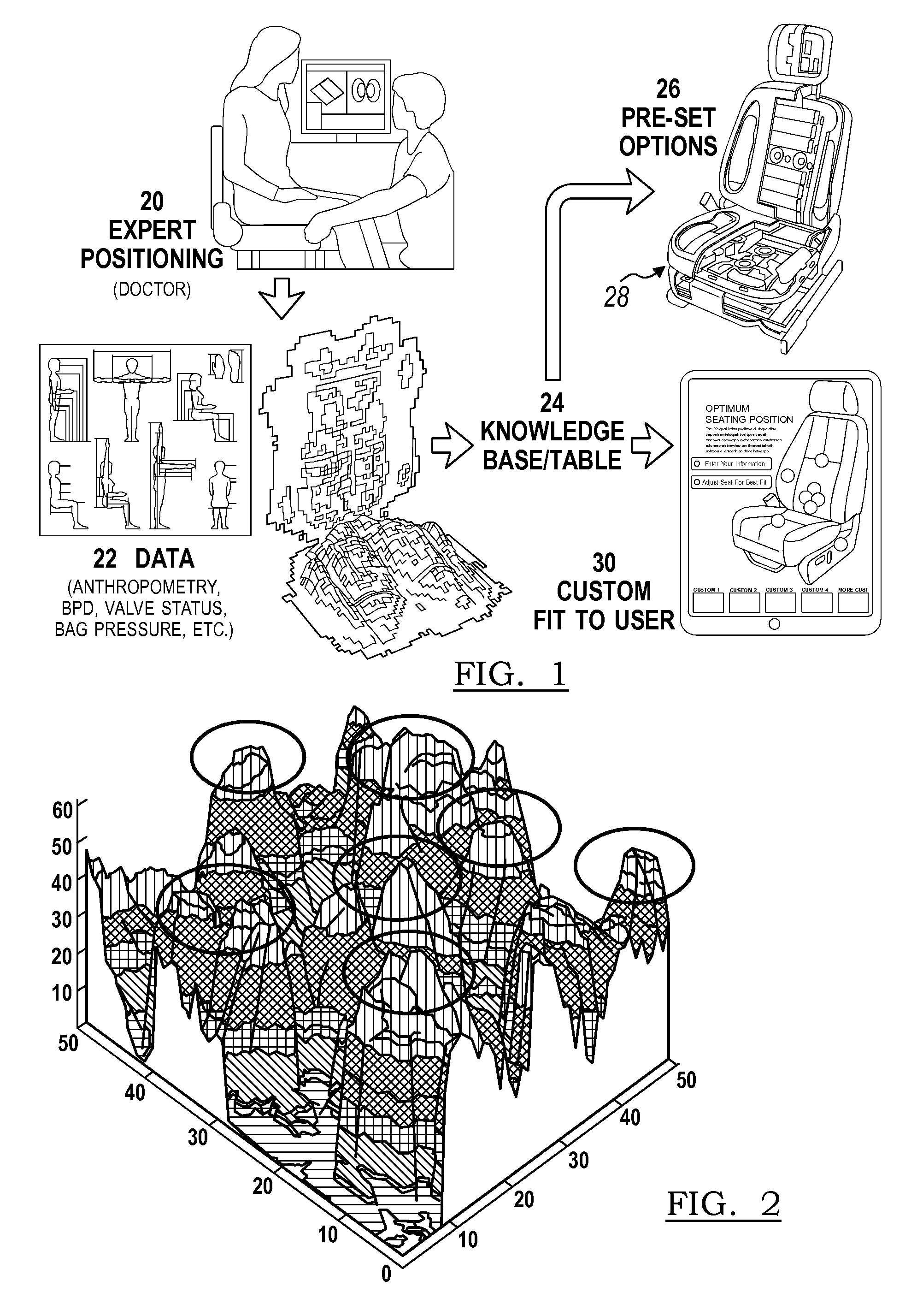
FIG. 1 is a flowchart of a method for determining various adjustment positions of a vehicle seat assembly for various users, according to an embodiment;
FIG. 2 is a graph of data collected in the method of FIG. 1;
FIG. 3 is a front perspective view of a vehicle seat assembly, illustrated partially disassembled, according to an embodiment;
FIG. 4 is a display image for a vehicle seating system according to an embodiment;
FIG. 5 is another display image for the vehicle seating system of FIG. 4;
FIG. 6 is another display image for the vehicle seating system of FIG. 4;
FIG. 7 is another display image for the vehicle seating system of FIG. 4;
FIG. 8 is another display image for the vehicle seating system of FIG. 4;
FIG. 9 is another display image for the vehicle seating system of FIG. 4;
FIG. 10 is a flowchart of a portion of an overall method for adjusting a vehicle seat assembly according to an embodiment;
FIG. 11 is a flowchart of another portion of an overall method for adjusting a vehicle seat assembly according to another embodiment;
FIG. 12 is a flowchart of another portion of an overall method for adjusting a vehicle seat assembly according to another embodiment;
FIG. 13 is a flowchart of another portion of an overall method for adjusting a vehicle seat assembly according to another embodiment; and
FIG. 14 is a flowchart of another portion of an overall method for adjusting a vehicle seat assembly according to another embodiment.
DETAILED DESCRIPTION
As required, detailed embodiments of the present invention are disclosed herein; however, it is to be understood that the disclosed embodiments are merely exemplary of the invention that may be embodied in various and alternative forms. The figures are not necessarily to scale; some features may be exaggerated or minimized to show details of particular components. Therefore, specific structural and functional details disclosed herein are not to be interpreted as limiting, but merely as a representative basis for teaching one skilled in the art to variously employ the present invention.
A comfort, posture and wellness seating system for vehicle seat assemblies provides a visual interface with adjustment hardware organically or inorganically. The system may be employed to properly configure any new or existing seating system. The system can also address specific comfort, posture and wellness needs or preferences, such as thoracic support. The seating system objectifies comfort data and biomechanical knowledge to make the data transferable.
The comfort, posture and wellness seating system integrates anthropometry, bio-mechanics, and historical seating comfort data. The seating system can be employed in original equipment for vehicles or in aftermarket products. Applicable markets include automotive, mass transit, airlines, etc., as well as non-vehicular seating such as office, home, commercial, and public venue seating.
Referring now to FIG. 1, a flowchart of a method for determining various adjustment positions of a vehicle seat assembly for various users is illustrated, according to an embodiment. Data collection may occur at block 20. The data collection 20 may include expert positioning of a suitable sample of occupants for optimal comfort, posture and/or wellness by a doctor or chiropractor. The data collection 20 can be used at specific sites on an ongoing basis if required. The expert input provides a high level of expert comfort, posture and wellness fitting.
The data 22 may be based on anthropometry, body pressure distribution (BPD), status of actuators (such as pressure of inflatable air bladders, status of valves or the like), or other data that provides a comfort, posture and wellness position of an adjustable vehicle seat assembly. The data is collected in a knowledge base 24 or table for setting adjustments based on categories of data. The knowledge base 24 may be compiled from the expert positioned data 20 and the occupant specific data 22. The setting adjustments from the knowledge base 24 are utilized for pre-set options 26 in a vehicle seat assembly 28. The setting adjustments 24 can be customized by a user at a controller or display 30.
Referring to FIG. 2, input data 20, 22 can be plotted versus adjustment settings 20, 24 for high level categorization. The settings 20, 24 can be categorized by topology clustering for setting the pre-set options 26. Various setting options 26 may be provided for various types of driving. For example a touring setting may provide per package settings and basic comfort, posture and wellness recommendations. The touring setting may also provide optimal visibility, use of features and controls, and the like. A performance setting may be provided for active drivers to provide a more erect position with firmer seating. Additionally, a luxury setting may be more reclined with softer seating.
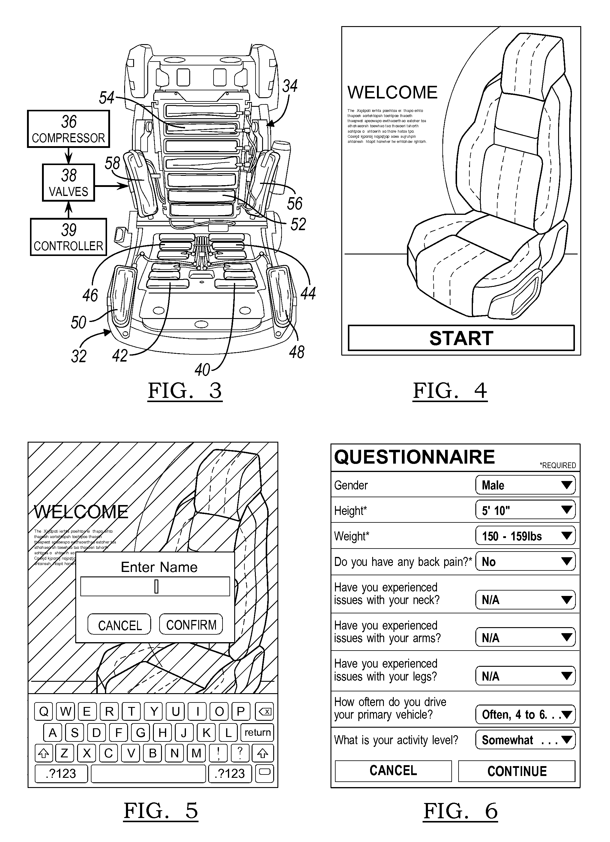
FIG. 3 illustrates the vehicle seat assembly 28 with a cover removed. The seat assembly 28 includes a seat cushion 32 adapted to be mounted for motor-driven adjustable translation in a fore and aft direction and in an up and down direction of a vehicle. The seat assembly 28 includes a seat back 34 pivotally connected to the seat cushion 32 to extend generally upright relative to the seat cushion 32 for motor-driven pivotal adjustment relative to the seat cushion 32. A head restraint (not shown) is mounted for motor-driven adjustable translation to the seat back 34.
At least one compressor 36 provides a source of air to the seat assembly 28. A plurality of valves 38 receive the compressed air and are controlled by a controller 39 for regulating compressed air into and out of the seat assembly 28. The seat cushion 32 includes a forward left air bladder 40, a forward right air bladder 42, a rear left air bladder 44, a rear right air bladder 46, a left side bolster air bladder 48, and a right side bolster air bladder 50. The seatback 34 includes a plurality of lumbar air bladders 52, a plurality of thoracic air bladders 54, a left side bolster air bladder 56, and a right side bolster air bladder 58. The valves 38 may be provided as a common valve bank that is housed in the seat back 34 or under the seat cushion 32; or the valves 38 may each be provided on each of the air bladders 40, 42, 44, 46, 48, 50, 52, 54, 56, 58. The compressor 36 may be provided in the seat back 34, the seat cushion 32 or concealed within the vehicle body. The controller 39 may be provided in a module under the seat cushion 32, and may be a multifunction controller that also controls other functions in the vehicle.
It is believed that supporting the thoracic region of the spine can reduce forces and support as much as one-third of the upper body mass. By increasing support of the upper body mass, loads are reduced on the muscles, ligaments, vertebrae and discs in the spine and pelvic regions. Decreased load reduces fatigue on these areas of the body. The thoracic air bladders 54 are adjustable to provide the right degree of support in the correct location necessary to reduce such loading.
The controller 39 receives the adjustment settings 24 from pre-set data 26 or from customized data 30. The data may be input from an interface that is provided in the vehicle. The interface may be integrated into the vehicle, such as an instrument panel display that is in suitable wired or wireless communication with the controller 39. The interface may be remote, such as a personal digital assistant (PDA) including phones, tablets and the like. The interface may be provided as a smart phone application, wherein users enter relevant information about themselves. The smart phone interface may not require on-site expertise or seat properties. The remote interface permits a user to transport settings to each vehicle, such as personal passenger vehicles, airline seating, rental cars, and the like.
FIGS. 4-9 illustrate display images from an interface, such as a tablet. FIG. 4 illustrates a welcome screen wherein a data collection process is initiated. FIG. 5 illustrates a screen wherein a user name is input to identify the user. FIG. 6 illustrates another input screen wherein biometric and personal health data, such as wellness and activity level, is collected. This data is utilized to adjust the seat to the pre-set options 26, based on prior-collected data 22 in knowledge base 24.
Each of the air bladders 40, 42, 44, 46, 48, 50, 52, 54, 56, 58 may include a pressure sensor to detect air pressure in the respective bladder 40, 42, 44, 46, 48, 50, 52, 54, 56, 58. Any pressure sensor is contemplated, such as a pneumatic pressure sensor at the outlet valve of each respective air bladder 40, 42, 44, 46, 48, 50, 52, 54, 56, 58. Pressure can also be sensed by contact pressure sensors disposed in front of or behind some or all of the respective air bladders, including on a front or rear surface thereof. The contact pressure sensors may include pressure-sensing mats, such as those available by Tekscan.RTM., Inc. of 307 West First Street. South Boston, Mass. 02127-1309, USA. FIG. 7 illustrates a depiction of the vehicle seat assembly 28 with zones ranging in color to depict a distribution of pressure upon the seat. This visualization may assist an occupant in positioning upon the seat assembly 28 with live visual feedback.
A dynamic comfort, posture and wellness option is offered. Selection of the dynamic comfort option measures the pressure in the sensors at FIG. 8, and displays a live view as in FIG. 9. The controller 39 compares the sensor values, and if the controller 39 determines that the occupant is not seated evenly, the controller 39 balances the air pressure in opposing air bladders to balance the occupant seating position.
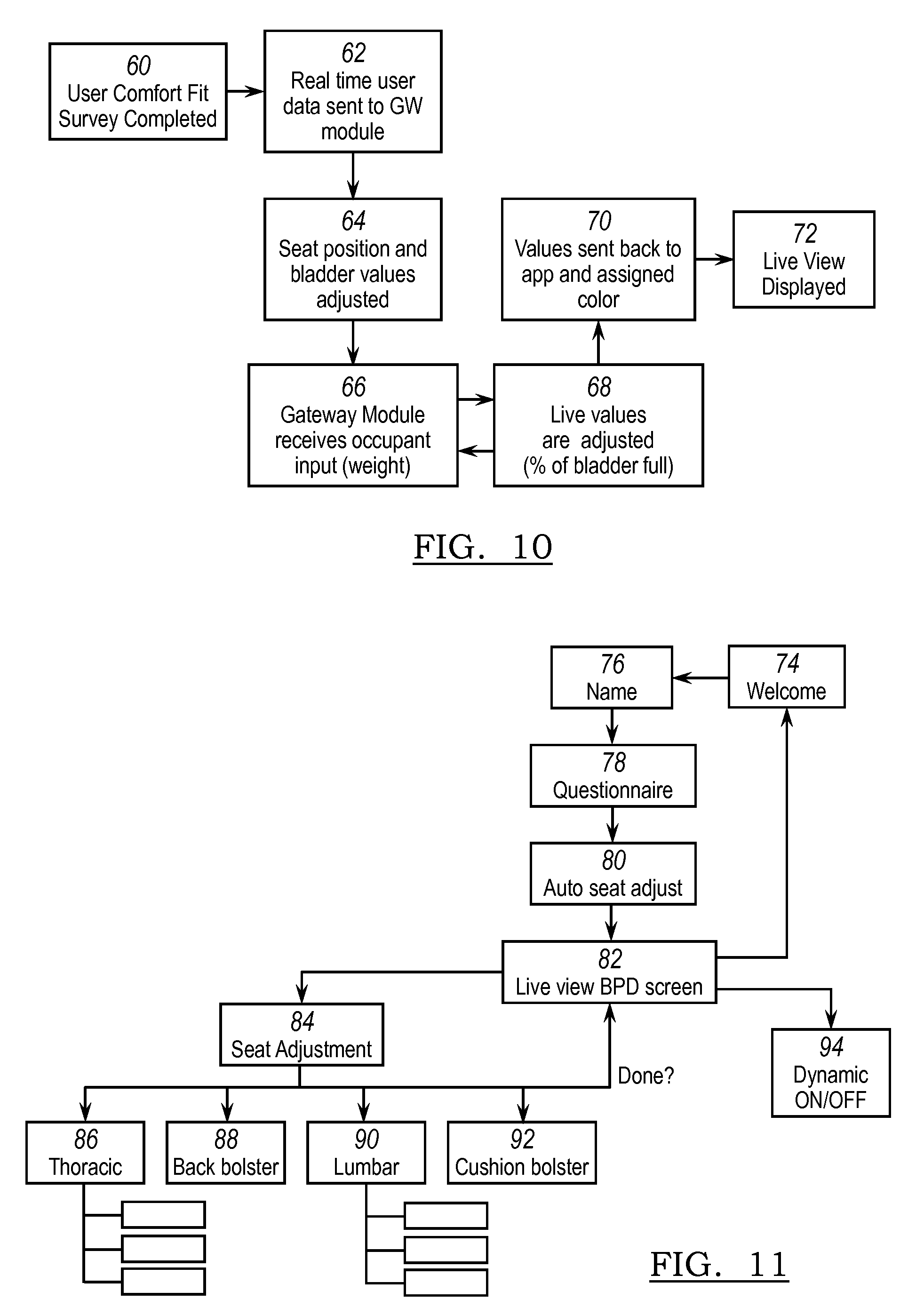
FIG. 10 depicts a flowchart for a method for adjusting the seat assembly 28 according to an embodiment. At block 60 the user comfort fit survey is completed. This process may be performed in an application on a PDA, tablet or smartphone, or in a controller in the vehicle. At block 62, real time user data is sent to a gateway module, or controller 39. In block 64, the seat assembly 28 is positioned, and the air bladder values are adjusted. At block 66, the gateway module receives an occupant weight distribution from the air bladder pressure sensors. At block 68 live values are adjusted, such as a percentage of bladder fullness. At block 70, the values are sent to the interface application, and the range of values is assigned a range of colors. In block 72, a live view is displayed, as in FIG. 9. Steps 66 and 68 are repeated for dynamically adjusting the seat assembly 28 to the occupant's position. Steps 66, 70 and 72 are repeated incrementally to provide the live view of the pressure distribution.
FIGS. 11-14 depict flowcharts for a method for adjusting the seat assembly 28 according to another embodiment. At block 74 a welcome screen initiates a data collection process. At block 76 a user name is input to identify the user. At block 78 another input screen includes a questionnaire wherein biometric and personal health data, such as wellness and activity level is collected. This data is utilized to adjust the seat at block 80 to the pre-set options 26, based on prior-collected data 22 in knowledge base 24. At block 82, a depiction of the vehicle seat assembly 28 is provided with zones ranging in color to depict a distribution of pressure upon the seat assembly 28. If manual adjustment is selected at block 84, the occupant can select a zone of the seat for adjustment, such as thoracic 86, back bolster 88, lumbar 90 and cushion bolster 92. Once manual adjustment is completed, the live view body pressure distribution (BPD) screen 82 is updated. If a dynamic mode is selected at block 84, then the adjustments and live view are updated based on the measurements from the pressure sensors and the biometric data.
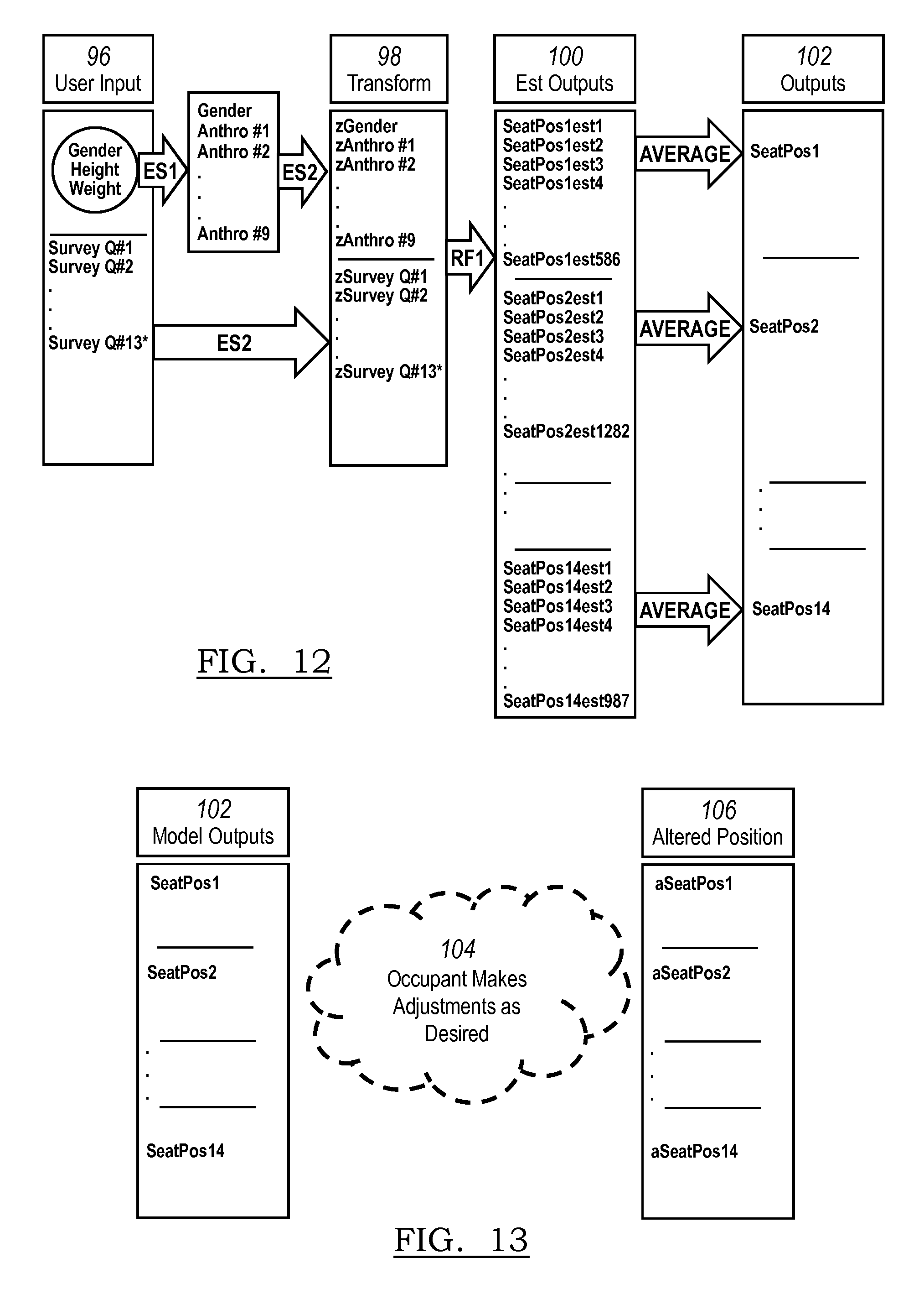
FIG. 12 more specifically illustrates a flow chart for a method for adjusting the seat assembly 28 according to another embodiment. The method employs an initial or crowd-sourced, position model, wherein user input data is collected at block 96. The model employs a plurality of if--then equations where each (transformed) input, block 98, finds a large number of combinatorial if--then fits to give an estimate of a seat position (e.g., horizontal position) block 100 for seat adjustment 102. For example, there is a vast plurality of possible estimates, for seat lift, but each set of user inputs will only match a finite number and produce an estimate.
FIG. 13 illustrates another portion of the method wherein the model outputs 102 are adjusted by the user 104 to provide customized user settings 106. The crowd sourced model outputs 102 provide an initial adjustment based on the collected data which can thereby permit user customization with minimal effort in adjusting the positions from predicted model outputs 102, instead of full adjustment from a reset position. The initial adjustments can be of seat cushion height, tilt, and fore-aft position, seat back recline angle, headrest position (up-down and/or fore-aft), and bladder inflations. Some or all of the foregoing can then be user customized.
FIG. 14 illustrates another portion of the embodiment of a method for adjustment of the seat assembly 28. From block 108, the altered positions are transformed, block 110, to estimated outputs 112 from the wellness expert position model to adjusted seat positions at block 114.
While various embodiments are described above, it is not intended that these embodiments describe all possible forms of the invention. Rather, the words used in the specification are words of description rather than limitation, and it is understood that various changes may be made without departing from the spirit and scope of the invention. Additionally, the features of various implementing embodiments may be combined to form further embodiments of the invention.
* * * * *
D00000
D00001
D00002
D00003
D00004
D00005
D00006
XML
uspto.report is an independent third-party trademark research tool that is not affiliated, endorsed, or sponsored by the United States Patent and Trademark Office (USPTO) or any other governmental organization. The information provided by uspto.report is based on publicly available data at the time of writing and is intended for informational purposes only.
While we strive to provide accurate and up-to-date information, we do not guarantee the accuracy, completeness, reliability, or suitability of the information displayed on this site. The use of this site is at your own risk. Any reliance you place on such information is therefore strictly at your own risk.
All official trademark data, including owner information, should be verified by visiting the official USPTO website at www.uspto.gov. This site is not intended to replace professional legal advice and should not be used as a substitute for consulting with a legal professional who is knowledgeable about trademark law.