Multi-layered cores with thermoplastic and thermoset layers for golf balls
Sullivan , et al.
U.S. patent number 10,322,318 [Application Number 15/672,713] was granted by the patent office on 2019-06-18 for multi-layered cores with thermoplastic and thermoset layers for golf balls. This patent grant is currently assigned to Acushnet Company. The grantee listed for this patent is Acushnet Company. Invention is credited to Mark L. Binette, Michael J. Sullivan.
| United States Patent | 10,322,318 |
| Sullivan , et al. | June 18, 2019 |
Multi-layered cores with thermoplastic and thermoset layers for golf balls
Abstract
Multi-piece golf balls containing a multi-layered core structure having layers with different hardness gradients and specific gravities are provided. The core structure includes a small, heavy inner core (center) having a relatively high specific gravity with metal material preferably dispersed in a first thermoset composition. The intermediate core layer is preferably formed from a thermoplastic composition such as an ethylene acid copolymer ionomer resin; and the outer core layer is preferably formed from a second thermoset composition. The resulting ball has high resiliency and good spin control.
| Inventors: | Sullivan; Michael J. (Old Lyme, CT), Binette; Mark L. (Mattapoisett, MA) | ||||||||||
|---|---|---|---|---|---|---|---|---|---|---|---|
| Applicant: |
|
||||||||||
| Assignee: | Acushnet Company (Fairhaven,
MA) |
||||||||||
| Family ID: | 50773769 | ||||||||||
| Appl. No.: | 15/672,713 | ||||||||||
| Filed: | August 9, 2017 |
Prior Publication Data
| Document Identifier | Publication Date | |
|---|---|---|
| US 20170368421 A1 | Dec 28, 2017 | |
Related U.S. Patent Documents
| Application Number | Filing Date | Patent Number | Issue Date | ||
|---|---|---|---|---|---|
| 14879130 | Oct 9, 2015 | 9731168 | |||
| 13686013 | Oct 13, 2015 | 9155937 | |||
| Current U.S. Class: | 1/1 |
| Current CPC Class: | A63B 37/0092 (20130101); A63B 37/0044 (20130101); A63B 37/0033 (20130101); A63B 37/0063 (20130101); A63B 37/0064 (20130101); A63B 37/0066 (20130101); A63B 37/0076 (20130101); A63B 37/0054 (20130101); A63B 37/0045 (20130101); A63B 37/0039 (20130101); A63B 37/0047 (20130101) |
| Current International Class: | A63B 37/04 (20060101); A63B 37/06 (20060101); A63B 37/00 (20060101) |
| Field of Search: | ;473/324-350 |
References Cited [Referenced By]
U.S. Patent Documents
| 4625964 | December 1986 | Yamada |
| 5048838 | September 1991 | Chikaraishi et al. |
| 5104126 | April 1992 | Gentiluomo |
| 5482285 | January 1996 | Yabuki et al. |
| 5772531 | June 1998 | Ohsumi et al. |
| 6277034 | August 2001 | Nesbitt et al. |
| 6494795 | December 2002 | Sullivan |
| 6500076 | December 2002 | Morgan et al. |
| 6692380 | February 2004 | Sullivan et al. |
| 6913548 | July 2005 | Moriyama et al. |
| 6986717 | January 2006 | Morgan et al. |
| 7410429 | August 2008 | Bulpett et al. |
| 7537529 | May 2009 | Bulpett et al. |
| 7537530 | May 2009 | Bulpett et al. |
| 7591742 | September 2009 | Sullivan et al. |
| 7651415 | January 2010 | Ladd et al. |
| 7654917 | February 2010 | Sullivan |
| 7708656 | May 2010 | Sullivan |
| 7713145 | May 2010 | Sullivan |
| 7713146 | May 2010 | Sullivan |
| 7722482 | May 2010 | Sullivan |
| 7731607 | June 2010 | Sullivan |
| 7744489 | June 2010 | Sullivan et al. |
| 7744490 | June 2010 | Sullivan et al. |
| 7753810 | July 2010 | Sullivan |
| 7815526 | October 2010 | Sullivan et al. |
| 7833112 | November 2010 | Sullivan |
| 7841955 | November 2010 | Sullivan |
| 7850549 | December 2010 | Sullivan |
| 7867107 | January 2011 | Sullivan |
| 7946934 | May 2011 | Sullivan et al. |
| 7963862 | June 2011 | Sullivan |
| 7963863 | June 2011 | Sullivan |
| 7976411 | July 2011 | Sullivan |
| 7980965 | July 2011 | Sullivan |
| 7993218 | August 2011 | Sullivan |
| 8137214 | March 2012 | Sullivan et al. |
| 8152655 | April 2012 | Comeau et al. |
| 8231482 | July 2012 | Sullivan |
| 8241147 | August 2012 | Sullivan |
| 9056225 | June 2015 | Sullivan |
| 9061180 | June 2015 | Sullivan |
| 9155937 | October 2015 | Sullivan |
| 9623287 | April 2017 | Sullivan |
| 9821193 | November 2017 | Sullivan |
| 2010/0075780 | March 2010 | Sullivan et al. |
| 2010/0099517 | April 2010 | Comeau et al. |
| 2010/0144466 | June 2010 | Sullivan et al. |
| 2011/0275456 | November 2011 | Sullivan et al. |
| 2011/0312441 | December 2011 | Sullivan et al. |
| 2012/0122610 | May 2012 | Sullivan et al. |
Attorney, Agent or Firm: Sullivan; Daniel W.
Parent Case Text
CROSS-REFERENCE TO RELATED APPLICATIONS
This application is a divisional of co-assigned U.S. patent application Ser. No. 14/879,130 having a filing date of Oct. 9, 2015, now allowed, which is a divisional of co-assigned U.S. patent application Ser. No. 13/686,013 having a filing date of Nov. 27, 2012, now issued as U.S. Pat. No. 9,155,937 with an issue date of Oct. 13, 2015, the entire disclosures of which are hereby incorporated by reference.
Claims
We claim:
1. A golf ball, comprising: a multi-layered core including i) an inner core comprising a metal material, the inner core having a diameter in the range of about 0.100 to about 1.100 inches, a specific gravity (SG.sub.inner), and an outer surface hardness (H.sub.center surface) and a center hardness (H.sub.center material), the H.sub.center surface being the same or less than the H.sub.center material to provide a zero or negative hardness gradient, wherein the inner core has a diameter in the range of about 0.100 to about 0.500 inches and specific gravity in the range of about 1.60 to about 6.25 g/cc; ii) an intermediate core layer comprising a thermoplastic material, the intermediate layer being disposed about the inner core and having a thickness in the range of about 0.050 to about 0.400 inches, a specific gravity (SG.sub.intermediate), and an outer surface hardness (H.sub.outer surface of IC) and an inner surface hardness (H.sub.inner surface of IC), the H.sub.outer surface of IC being greater than the H.sub.inner surface of IC to provide a positive hardness gradient; and iii) an outer core layer comprising a thermoset material, the outer core layer being disposed about the inner core and having a thickness in the range of about 0.200 to about 0.750 inches, a specific gravity (SG.sub.outer), and an outer surface hardness ((H.sub.outer surface of OC) of 40 to 85 Shore C and an inner surface hardness (H.sub.inner surface of OC) of 42 to 87 Shore C, the H.sub.outer surface of OC being the same or less than the H.sub.inner surface of OC to provide a zero or negative hardness gradient, wherein the SG.sub.inner is greater than the SG.sub.outer and SG.sub.intermediate; and a cover having at least one layer disposed about the multi-layered core.
2. The golf ball of claim 1, wherein the outer core layer has a thickness in the range of about 0.250 to about 0.750 inches and specific gravity in the range of about 0.60 to about 2.90 g/cc.
3. A golf ball, comprising: a multi-layered core including i) an inner core comprising a metal material, the the inner core having a diameter in the range of about 0.100 to about 1.100 inches, a specific gravity (SG.sub.inner), and an outer surface hardness (H.sub.center surface) and a center hardness (H.sub.center material), the H.sub.center surface being the same or less than the H.sub.center material to provide a zero or negative hardness gradient; ii) an intermediate core layer comprising a thermoplastic material, the intermediate layer being disposed about the inner core and having a thickness in the range of about 0.050 to about 0.400 inches, a specific gravity (SG.sub.intermediate) and an outer surface hardness (H.sub.outer surface of IC) and an inner surface hardness (H.sub.inner surface of IC), the H.sub.outer surface of IC being the same or less than the H.sub.inner surface of IC to provide a zero or negative hardness gradient; and iii) an outer core layer comprising a thermoset material, the outer core layer being disposed about the inner core and having a thickness in the range of about 0.200 to about 0.750 inches, a specific gravity (SG.sub.outer), and an outer surface hardness ((H.sub.outer surface of OC) of 42 to 92 Shore C and an inner surface hardness (H.sub.inner surface of OC) of 40 to 89 Shore C, the H.sub.outer surface of OC being greater than the H.sub.inner surface of OC to provide a positive hardness gradient, wherein the SG.sub.inner is greater than the SG.sub.outer, and SG.sub.intermediate; and a cover having at least one layer disposed about the multi-layered core.
4. The golf ball of claim 3, wherein the inner core has a diameter in the range of about 0.100 to about 0.500 inches and specific gravity in the range of about 1.60 to about 6.25 g/cc.
5. The golf ball of claim 3, wherein the outer core layer has a thickness in the range of about 0.250 to about 0.750 inches and specific gravity in the range of about 0.60 to about 2.90 g/cc.
6. A golf ball, comprising: a multi-layered core including i) an inner core comprising a metal material, the inner core having a diameter in the range of about 0.100 to about 1.100 inches, a specific gravity (SG.sub.inner), and an outer surface hardness (H.sub.center surface) and a center hardness (H.sub.center material), the H.sub.center surface being greater than the H.sub.center material provide a positive hardness gradient; ii) an intermediate core layer comprising a thermoplastic material, the Intermediate layer being disposed about the inner core and having a thickness in the range of about 0.050 to about 0.400 inches, a specific gravity (SG.sub.intermediate), and an outer surface hardness (H.sub.outer surface of IC) and an inner surface hardness (H.sub.inner surface of IC), the H.sub.outer surface of IC being the same or less than the H.sub.inner surface of IC to provide a zero or negative hardness gradient; and iii) an outer core layer comprising a thermoset material, the outer core layer being disposed about the inner core and having a thickness in the range of about 0.200 to about 0.750 inches, a specific gravity (SG.sub.outer), and an outer surface hardness ((H.sub.outer surface of OC) of 40 to 85 Shore C and an inner surface hardness (H.sub.inner surface of OC) of 42 to 87 Shore C, the H.sub.outer surface of OC being the same or less than the H.sub.inner surface of OC to provide a zero or negative hardness gradient, wherein the SG.sub.inner is greater than the SG.sub.outer; and a cover having at least one layer disposed about the multi-layered core.
7. The golf ball of claim 6, wherein the inner core has a diameter in the range of about 0.100 to about 0.500 inches and specific gravity in the range of about 1.60 to about 6.25 g/cc.
8. The golf ball of claim 6, wherein the outer core layer has a thickness in the range of about 0.250 to about 0.750 Inches and specific gravity in the range of about 0.60 to about 2.90 g/cc.
Description
BACKGROUND OF THE INVENTION
Field of the Invention
The present invention generally relates to multi-piece golf balls having a solid core of three layers comprising thermoplastic and thermoset layers. The multi-layered core has a small, heavy inner core (center), intermediate core layer, and surrounding outer core layer. Preferably, the center comprises a metal material; the intermediate core layer comprises a thermoplastic material; and the outer core comprises a thermoset material such as rubber. The core layers have different hardness gradients and specific gravity values. The ball further includes a cover of at least one layer.
Brief Review of the Related Art
Golf balls containing multi-layered cores are used today by professional golfers and amateur golfers. The core of the ball is protected by a cover which may be single or multi-layered. Manufacturers of golf balls use different core constructions to impart specific properties and features to the balls.
For example, the core is the primary source of resiliency for the golf ball and is often referred to as the "engine" of the ball. The resiliency or coefficient of restitution ("COR") of a golf ball (or golf ball component, particularly a core) means the ratio of a ball's rebound velocity to its initial incoming velocity when the ball is fired out of an air cannon into a rigid plate. The COR for a golf ball is written as a decimal value between zero and one. A golf ball may have different COR values at different initial velocities. The United States Golf Association (USGA) sets limits on the initial velocity of the ball so one objective of golf ball manufacturers is to maximize the COR under these conditions. Balls (or cores) with a high rebound velocity have a relatively high COR value. Such golf balls rebound faster, retain more total energy when struck with a club, and have longer flight distances as opposed to balls with lower COR values. Ball resiliency and COR properties are particularly important for long distance shots. For example, balls having high resiliency and COR values tend to travel a far distance when struck by a driver club from a tee. The spin rate of the ball also is an important property. Balls having a relatively high spin rate are particularly desirable for relatively short distance shots made with irons and wedge clubs. Professional and highly skilled amateur golfers can place a back-spin on such balls more easily. By placing the right amount of spin and touch on the ball, the golfer has better control over shot accuracy and placement. This is particularly important for approach shots near the green and helps improve scoring performance.
Over the years, golf ball manufacturers have looked at adjusting the density or specific gravity among the multiple layers of the golf ball to control its spin rate. In general, the total weight of a golf ball needs to conform to weight limits set by the United States Golf Association ("USGA"). Although the total weight of the golf ball is mandated, the distribution of weight within the ball can vary. Redistributing the weight or mass of the golf ball either towards the center of the ball or towards the outer surface of the ball changes its flight and spin properties.
For example, the weight can be shifted towards the center of the ball to increase the spin rate of the ball as described in Yamada, U.S. Pat. No. 4,625,964. In the '964 Patent, the core composition preferably contains 100 parts by weight of polybutadiene rubber; 10 to 50 parts by weight of zinc acrylate or zinc methacrylate; 10 to 150 parts by weight of zinc oxide; and 1 to 5 parts by weight of peroxide as a cross-linking or curing agent. The inner core has a specific gravity of at least 1.50 in order to make the spin rate of the ball comparable to wound balls. The ball further includes a cover an intermediate layer disposed between the core and cover, wherein the intermediate layer has a lower specific gravity than the core.
Chikaraishi et al., U.S. Pat. No. 5,048,838 discloses a three-piece golf ball containing a two-piece solid core and a cover. The inner core has a diameter in the range of 15-25 mm, a weight of 2-14 grams, a specific gravity of 1.2 to 4.0, and a hardness of 55-80 JISC. The specific gravity of the outer core layer is less than the specific gravity of the inner core by 0.1 to 3.0. less than the specific gravity of the inner core. The inner and outer core layers are formed from rubber compositions.
Gentiluomo, U.S. Pat. No. 5,104,126 discloses a three-piece ball with a dense inner core made of steel, lead, brass, zinc, copper, and a filled elastomer, wherein the core has a specific gravity of at least 1.25. The inner core is encapsulated by a lower density syntactic foam composition, and the core construction is encapsulated by an ionomer cover.
Yabuki et al., U.S. Pat. No. 5,482,285 discloses a three-piece golf ball having an inner core and outer core encapsulated by an ionomer cover. The specific gravity of the outer core is reduced so that it falls within the range of 0.2 to 1.0. The specific gravity of the inner core is adjusted so that the total weight of the inner/outer core falls within a range of 32.0 to 39.0 g.
Nesbitt and Binette, U.S. Pat. No. 6,277,934 disclose a non-wound, multi-piece golf ball containing a spherical metal core component having a specific gravity of about 1.5 to about 19.4; and an outer core layer disposed about said spherical metal core component, wherein the core layer has a specific gravity of less than 1.2. The metal core is preferably contains a metal selected from steel, titanium, brass, lead, tungsten, molybdenum, copper, nickel, iron, and combinations thereof. Polybutadiene rubber compositions containing metallic powders can be used to form the core. The core assembly preferably has a coefficient of restitution of at least 0.730.
Sullivan, U.S. Pat. No. 6,494,795 discloses a golf ball comprising an inner core having a specific gravity of greater than 1.8 encased within a first mantle surrounding the inner core. A portion of the first mantle comprises a low specific gravity layer having a specific gravity of less than 0.9. The core may be made from a high density metal or from metal powder encased in a polymeric binder. High density metals such as steel, tungsten, lead, brass, bronze, copper, nickel, molybdenum, or alloys may be used. The mantle layer surrounding the inner core may be made from a thermoset or thermoplastic material such as epoxy, urethane, polyester, polyurethane, or polyurea.
Sullivan, U.S. Pat. No. 6,692,380 discloses a golf ball comprising an inner core having a specific gravity of at least 3, a diameter of about 0.40 to about 0.60 inches and preferably comprises a polymeric matrix of polyurethane, polyurea, or blends thereof. The outer core may be made from a polybutadiene rubber. The specific gravity of the compositions may be adjusted by adding fillers such as metal powder, metal alloy powder, metal oxide, metal stearates, particulates, and carbonaceous material.
Morgan and Jones, U.S. Pat. No. 6,986,717 discloses a golf ball containing a high-specific gravity central sphere encapsulated in a soft and resilient shell, preferably formed of a polybutadiene rubber. This shell is subsequently wound with thread that is preferably elastic to form a wound core. This wound core is then covered with a cover material such as balata, gutta percha, an ionomer or a blend of ionomers, polyurethane, polyurea-based composition, and epoxy-urethane-based compositions. The sphere is formed of metallic powder and a thermoset or thermoplastic binder material. Metals such as tungsten, steel, brass, titanium, lead, zinc, copper, bismuth, nickel, molybdenum, iron, bronze, cobalt, silver, platinum, and gold can be used. Preferably, the metal sphere has a specific gravity of at least 6.0 and a diameter of less than 0.5 inches.
Ladd et al., U.S. Pat. No. 7,651,415 discloses a golf ball having four or more layers including a cover and three or more inner layers. The inner layers include a core and two or more intermediate layers. The inner layers are formulated such that the density of the inner layer is preferably twice (2.times.) the density of an adjacent outer layer. The '415 Patent discloses that the core, intermediate layers, and cover layers may be made from thermoplastic and thermoset compositions, particularly highly-neutralized polymers.
Although some conventional multi-layered core constructions are generally effective in providing high resiliency golf balls, there is a continuing need for improved core constructions in golf balls. Particularly, it would be desirable to have multi-layered core constructions with selective specific gravities and mass densities to provide the ball with good flight distance along with spin control. The present invention provides core constructions and golf balls having such properties as well as other advantageous features and benefits.
SUMMARY OF THE INVENTION
The present invention provides a multi-piece golf ball comprising a solid core having three layers and a cover having at least one layer. The golf ball may have different constructions. For example, in one version, the multi-layered core includes: i) an inner core (center) comprising a metal material, wherein the inner core has a diameter in the range of about 0.100 to about 1.100 inches and a specific gravity (SG.sub.inner); ii) an intermediate layer comprising a thermoplastic material, wherein the intermediate layer is disposed about the inner core and has a thickness in the range of about 0.050 to about 0.400 inches and a specific gravity (SG.sub.intermediate); and iii) an outer core layer comprising a thermoset material, wherein the outer cover layer is disposed about the intermediate core layer and has a thickness in the range of about 0.200 to about 0.750 inches and a specific gravity (SG.sub.outer). Preferably, the SG.sub.inner is greater than the SG.sub.intermediate and SG.sub.outer. And, preferably the volume of the outer core layer is greater than the volume of the inner core and volume of the intermediate core layer.
The core layers may have different hardness gradients. For example, each core layer may have a positive, zero, or negative hardness gradient. In one embodiment, the inner core has a positive hardness gradient; the intermediate core layer has a positive hardness gradient; and the outer core layer has a zero or negative hardness gradient. In a second embodiment, each of the core layers has a positive hardness gradient. In yet another embodiment, the inner core has a zero or negative hardness gradient; the intermediate core layer has a positive hardness gradient; and the outer core layer has a zero or negative hardness gradient. In an alternative version, each of the inner and intermediate core layers has a zero or negative hardness gradient, while the outer core layer has a positive hardness gradient. In a further version, the inner core has a positive hardness gradient, while each of the intermediate and outer core layers has a zero or negative hardness gradient.
Suitable metal materials for making the inner core include, but are not limited to, copper, steel, brass, tungsten, titanium, aluminum, magnesium, molybdenum, cobalt, nickel, iron, tin, zinc, barium, bismuth, bronze, silver, gold, and platinum, and alloys and combinations thereof. The metal material is dispersed preferably in a thermoset material. Preferably, the inner core has a diameter in the range of about 0.100 to about 0.500 inches and specific gravity in the range of about 1.60 to about 6.25 g/cc. Preferably, the intermediate core layer has a thickness in the range of about 0.050 to about 0.400 inches and specific gravity in the range of about 0.7 to about 3.00 g/cc. Preferably, the outer core layer has a thickness in the range of about 0.250 to about 0.750 inches and specific gravity in the range of about 0.60 to about 2.90 g/cc.
BRIEF DESCRIPTION OF THE DRAWINGS
The novel features that are characteristic of the present invention are set forth in the appended claims. However, the preferred embodiments of the invention, together with further objects and attendant advantages, are best understood by reference to the following detailed description in connection with the accompanying drawings in which:
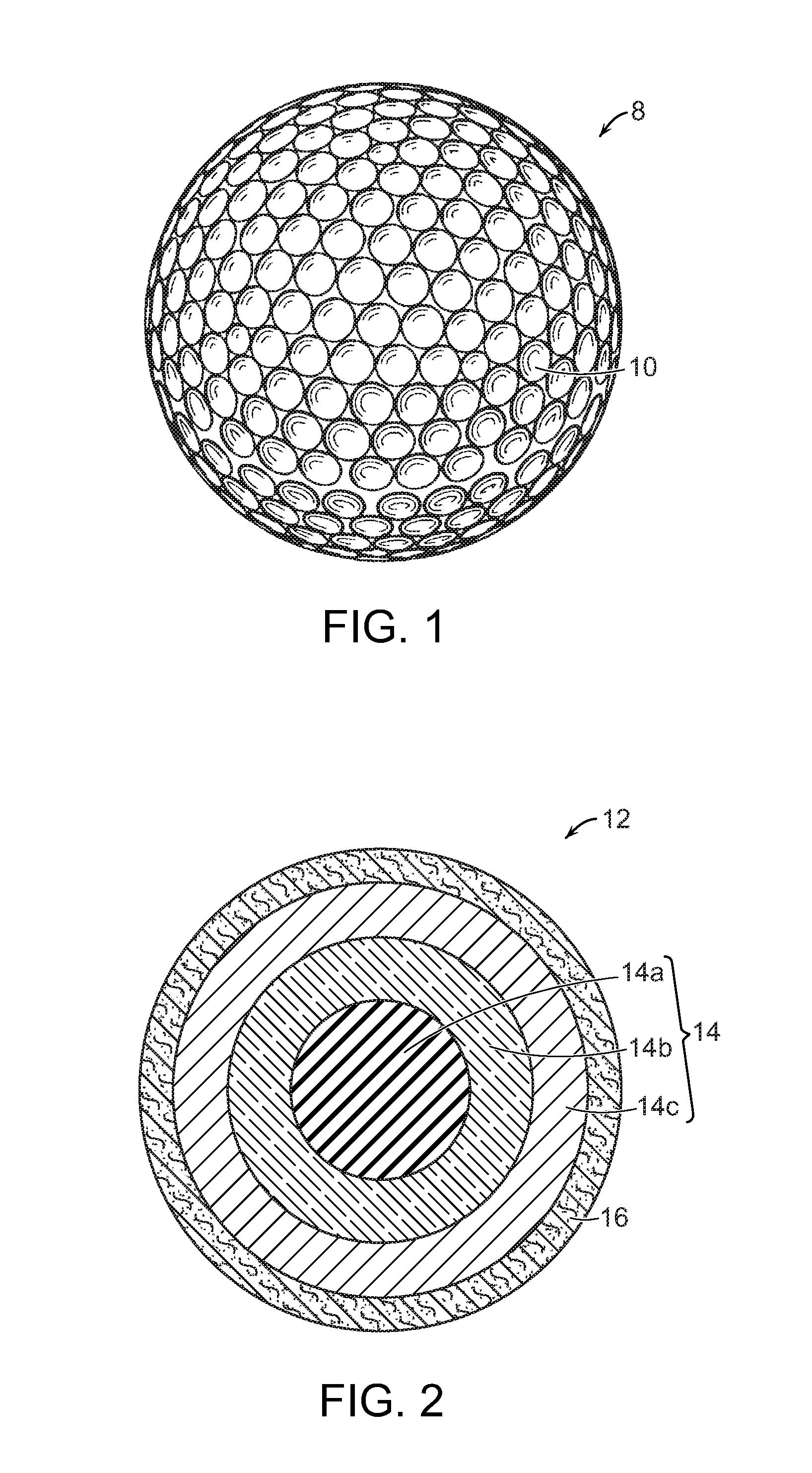
FIG. 1 is a front view of a dimpled golf ball made in accordance with the present invention;
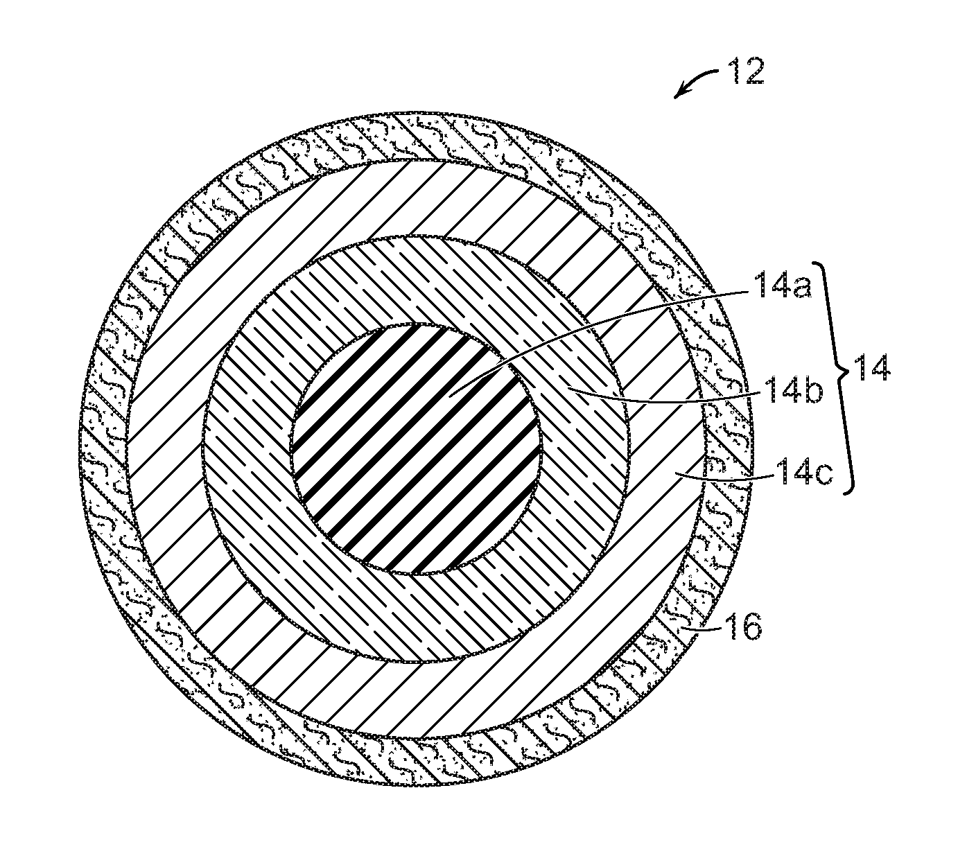
FIG. 2 is a cross-sectional view of a four-piece golf ball having a multi-layered core made in accordance with the present invention;
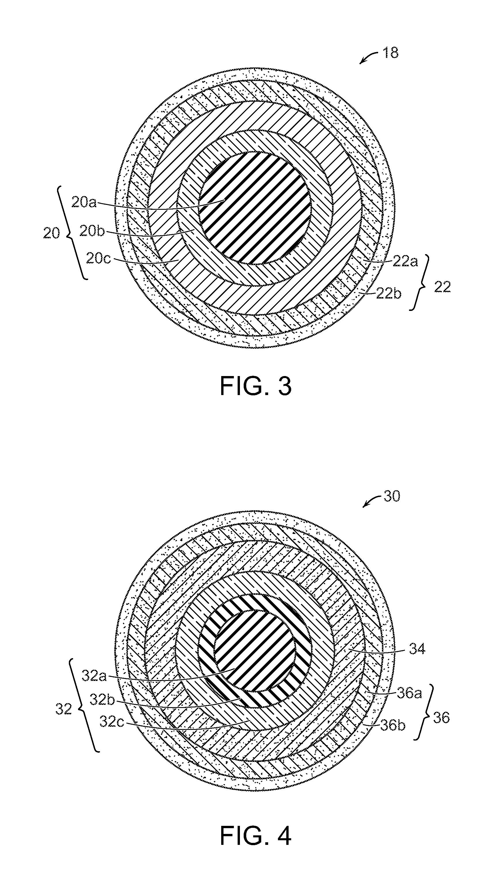
FIG. 3 is a cross-sectional view of a five-piece golf ball having a multi-layered core made in accordance with the present invention; and
FIG. 4 is a cross-sectional view of a six-piece golf ball having a multi-layered core made in accordance with the present invention.
DETAILED DESCRIPTION OF THE INVENTION
Golf Ball Constructions
Golf balls having various constructions may be made in accordance with this invention. For example, golf balls having four-piece, five-piece, and six-piece constructions with single or multi-layered cover materials may be made. The term, "layer" as used herein means generally any spherical portion of the golf ball. More particularly, in one version, a four-piece golf ball having a multi-layered core and single-layered cover is made. The multi-layered core includes an inner core (center) and surrounding intermediate and outer core layers. In another version, a five-piece golf ball comprising a multi-layered core and dual-cover (inner cover and outer cover layers) is made. In yet another construction, a six-piece golf ball having a multi-layered core; a casing layer, and cover layer(s) may be made. As used herein, the term, "casing layer" means a layer of the ball disposed between the multi-layered core subassembly and cover. The casing layer also may be referred to as a mantle or intermediate layer. The diameter and thickness of the different layers along with properties such as hardness and compression may vary depending upon the construction and desired playing performance properties of the golf ball.
Referring to FIG. 1, a front perspective view of a finished golf ball that can be made in accordance with this invention is generally indicated at (8). The dimples (10) in the outer cover may have various shapes and be arranged in various patterns to modify the aerodynamic properties of the ball as needed. In FIG. 2, a cross-sectional view of one version of a golf ball that can be made in accordance with this invention is generally indicated at (12). The ball (12) contains a multi-layered core (14) having an inner core (center) (14a), intermediate core layer (14b), and outer core layer (14c) surrounded by a single-layered cover (16). The inner core (14a) is relatively small in volume and preferably has a diameter within a range of about 0.100 to about 1.100 inches. For example, the inner core (14a) may have a diameter within a range of about 0.100 to about 0.500 inches. In another example, the inner core may have a diameter within a range of about 0.300 to about 0.800 inches. More particularly, the inner core (14a) preferably has a diameter size with a lower limit of about 0.10 or 0.12 or 0.15 or 0.25 or 0.30 or 0.35 or 0.45 or 0.55 inches and an upper limit of about 0.60 or 0.65 or 0.70 or 0.80 or 0.90 or 1.00 or 1.10 inches. Meanwhile, the intermediate core layer (14b) preferably has a thickness within a range of about 0.050 to about 0.400 inches. More particularly, the intermediate core layer preferably has a lower limit of about 0.050 or 0.060 or 0.070 or 0.075 or 0.080 inches and an upper limit of about 0.090 or 0.100 or 0.130 or 0.200 or 0.250 or 0.300 or 0.400 inches. Lastly, the outer core layer (14c) preferably has a thickness in the range of about 0.200 to about 0.750 inches, more preferably about 0.400 to about 0.600 inches. In one embodiment, the lower limit of the thickness is about 0.200 or 0.250 or 0.300 or 0.340 or 0.400 inches and the upper limit is about 0.500 or 0.550 or 0.600 or 0.650 or 0.700 or 0.750 inches.
In another version, as shown in FIG. 3, the golf ball (18) contains a multi-layered core (20) having an inner core (center) (20a), intermediate core layer (20b), and outer core layer (20c). The multi-layered core (20) is surrounded by a multi-layered cover (22) having an inner cover layer (22a) and outer cover layer (22b). Lastly, in FIG. 4, a six-piece ball (30) containing a multi-layered core (32) comprising inner (32a), intermediate (32b), and outer core (32c) layers is shown. A casing or mantle layer (34) is disposed between the core structure (32) and multi-layered cover (36). The ball may include one or more casing layers (34) disposed between the core (32) and cover (36) structures. The multi-layered cover (36) includes inner (36a) and outer (36c) cover layers. It should be understood that the golf balls shown in FIGS. 1-4 are for illustrative purposes only and not meant to be restrictive.
Golf balls made in accordance with this invention can be of any size, although the USGA requires that golf balls used in competition have a diameter of at least 1.68 inches. For play outside of United States Golf Association (USGA) rules, the golf balls can be of a smaller size. Normally, golf balls are manufactured in accordance with USGA requirements and have a diameter in the range of about 1.68 to about 1.80 inches. As discussed further below, the golf ball contains a cover which may be multi-layered and in addition may contain intermediate (casing) layers, and the thickness levels of these layers also must be considered. Thus, in general, the multi-layer core structure (14) normally has an overall diameter within a range having a lower limit of about 1.00 or 1.20 or 1.30 or 1.40 inches and an upper limit of about 1.58 or 1.60 or 1.62 or 1.66 inches, and more preferably in the range of about 1.3 to 1.65 inches. In one embodiment, the diameter of the core subassembly (14) is in the range of about 1.45 to about 1.62 inches.
As discussed further below, various compositions may be used to make the multi-layered core structures of the golf balls of this invention. The golf balls may contain certain fillers to adjust the specific gravity and weight of the core layers as needed. Preferably, the inner core (center) has a specific gravity within a range having a lower limit of about 1.18 or 1.50 or 1.60 or 1.80 or 2.00 or 2.50 g/cc and an upper limit of about 3.00 or 3.50 or 4.00 or 4.25 or 5.00 or 5.50 or 5.80 or 6.00 or 6.25 or 7.00 g/cc. In a preferred embodiment, the inner core has a specific gravity of about 1.60 to about 6.25 g/cc, more preferably about 1.80 to about 5.00 g/cc. Meanwhile, the intermediate (14b) and outer core (14c) layers preferably have relatively low specific gravities. The intermediate (14b) and outer core (14c) layers each preferably have a specific gravity within a range having a lower limit of about 0.40 or 0.60 or 0.80 or 1.00 or 1.20 or 1.30 or 1.60 or 2.00 or 2.20 and an upper limit of about 2.80 or 2.90 or 3.00 or 3.40 or 3.80 or 4.00 or 4.10 or 4.40 or 4.90 or g/cc. Preferably, the specific gravity of the inner core (14a) is greater than the specific gravity of the intermediate core layer (14b) and the specific gravity of the outer core layer (14c). And, preferably, the specific gravity of the intermediate core layer (14b) is greater than the specific gravity of the outer core layer (14c). In one embodiment, the specific gravity of the inner core layer (14a) is greater than 6.00 g/cc; the specific gravity of the intermediate core layer (14b) is in the range of 4.00 g/cc to less than 6.00 g/cc; and the specific gravity of the outer core layer is less than 4.00 g/cc.
The compositions used to make the different core layers (14a, 14b, and 14c) may contain various fillers in varying amounts to achieve the desired specific gravity levels. Also, the amount of fillers used in the compositions is adjusted so the weight of the golf ball does not exceed limits set by USGA rules. The USGA has established a maximum weight of 45.93 g (1.62 ounces). For play outside of USGA rules, the golf balls can be heavier. In one preferred embodiment, the weight of the multi-layered core is in the range of about 28 to about 38 grams.
Core Structure
As discussed above, the core preferably has a multi-layered structure comprising an inner core, intermediate core layer, and outer core layer. The intermediate core layer is disposed about the inner core, and the outer core layer surrounds the intermediate core layer. The hardness of the core subassembly (inner core, intermediate core layer, and outer core layer) is an important property. In general, cores with relatively high hardness values have higher compression and tend to have good durability and resiliency. However, some high compression balls are stiff and this may have a detrimental effect on shot control. For example, some of these harder balls tend to have a low spin rate and this makes the ball more difficult to control. This can be particularly troubling when making approach shots near the green. Thus, the optimum balance of hardness in the core subassembly needs to be attained.
In one preferred golf ball, the inner core (center) has a "positive" hardness gradient (that is, the outer surface of the inner core is harder than its geometric center); the intermediate core layer has a "positive" hardness gradient (that is, the outer surface of the intermediate core layer is harder than the inner surface of the intermediate core layer); and the outer core layer has a "positive" hardness gradient (that is, the outer surface of the outer core layer is harder than the inner surface of the outer core layer.) In such cases where the inner core, intermediate, and outer core layer each has a "positive" hardness gradient, the outer surface hardness of the outer core layer is preferably greater than the material hardness of the inner core (center). In one preferred version, the positive hardness gradient of the inner core is in the range of about 2 to about 40 Shore C units and even more preferably about 10 to about 25 Shore C units; while the positive hardness gradient of the intermediate core is in the range of about 1 to about 5 Shore C; and the positive hardness gradient of the outer core is in the range of about 2 to about 20 Shore C and even more preferably about 3 to about 10 Shore C.
In an alternative version, the inner core may have a positive hardness gradient; the intermediate core layer may have a "zero" hardness gradient (that is, the hardness values of the outer surface of the intermediate core layer and the inner surface of the intermediate core layer are substantially the same) or a "negative" hardness gradient (that is, the outer surface of the intermediate core layer is softer than the inner surface of the intermediate core layer); and the outer core layer may have a "zero" hardness gradient (that is, the hardness values of the outer surface of the outer core layer and the inner surface of the outer core layer are substantially the same) or a "negative" hardness gradient (that is, the outer surface of the outer core layer is softer than the inner surface of the outer core layer.) For example, in one example, the inner core has a positive hardness gradient; the intermediate core layer has a zero hardness gradient; and the outer core layer has a negative hardness gradient in the range of about 2 to about 25 Shore C.
In another version, the inner core (center) has a zero or negative hardness gradient, while the intermediate core layer has a positive hardness gradient, and the outer core has a zero or negative hardness gradient. In yet another version, both the inner core and intermediate core layers have a zero or negative hardness gradient, while the outer core layer has a positive hardness gradient. Still yet, in a particularly preferred embodiment, both the inner core and intermediate core layers have positive hardness gradients (more preferably within the range of about 2 to about 40 Shore C), while the outer core layer has a zero or negative hardness gradient.
In general, hardness gradients are further described in Bulpett et al., U.S. Pat. Nos. 7,537,529 and 7,410,429, the disclosures of which are hereby incorporated by reference. Methods for measuring the hardness of the inner core, intermediate core, and outer core layers along with other layers in the golf ball and determining the hardness gradients of the various layers are described in further detail below. The core layers have positive, negative, or zero hardness gradients defined by hardness measurements made at the outer surface of the inner core (or outer surface of the outer core layer) and radially inward towards the center of the inner core (or inner surface of the inner core layer). These measurements are made typically at 2-mm increments as described in the test methods below. In general, the hardness gradient is determined by subtracting the hardness value at the innermost portion of the component being measured (for example, the center of the inner core or inner surface of the intermediate or outer core layer) from the hardness value at the outer surface of the component being measured (for example, the outer surface of the inner core or outer surface of the intermediate or outer core layer).
Positive Hardness Gradient.
For example, if the hardness value of the outer surface of the inner core is greater than the hardness value of the inner core's geometric center (that is, the inner core has a surface harder than its center), the hardness gradient will be deemed "positive" (a larger number minus a smaller number equals a positive number.) For example, if the outer surface of the inner core has a hardness of 67 Shore C and the center of the inner core has a hardness of 60 Shore C, then the inner core has a positive hardness gradient of 7. Likewise, if the outer surface of the intermediate (or outer) core layer has a greater hardness value than the inner surface of the intermediate (or outer) core layer respectively, the given intermediate (and/or outer) core layer will be considered to have a positive hardness gradient.
Negative Hardness Gradient.
On the other hand, if the hardness value of the outer surface of the inner core is less than the hardness value of the inner core's geometric center (that is, the inner core has a surface softer than its center), the hardness gradient will be deemed "negative." For example, if the outer surface of the inner core has a hardness of 68 Shore C and the center of the inner core has a hardness of 70 Shore C, then the inner core has a negative hardness gradient of 2. Likewise, if the outer surface of the intermediate (or outer) core layer has a lesser hardness value than the inner surface of the intermediate (or outer) core layer, the given intermediate (and/or outer) core layer will be considered to have a negative hardness gradient.
Zero Hardness Gradient.
In another example, if the hardness value of the outer surface of the inner core is substantially the same as the hardness value of the inner core's geometric center (that is, the surface of the inner core has about the same hardness as the center), the hardness gradient will be deemed "zero." For example, if the outer surface of the inner core and the center of the inner core each has a hardness of 65 Shore C, then the inner core has a zero hardness gradient. Likewise, if the outer surface of the outer core layer has a hardness value approximately the same as the inner surface of the outer core layer, the outer core layer will be considered to have a zero hardness gradient. Also, if the outer surface of the intermediate core layer has a hardness value approximately the same as the inner surface of the intermediate core layer, the intermediate core layer will be considered to have a zero hardness gradient.
More particularly, the term, "positive hardness gradient" as used herein means a hardness gradient of positive 3 Shore C or greater, preferably 7 Shore C or greater, more preferably 10 Shore C, and even more preferably 20 Shore C or greater. The term, "zero hardness gradient" as used herein means a hardness gradient of less than 3 Shore C, preferably less than 1 Shore C and may have a value of zero or negative 1 to negative 10 Shore C. The term, "negative hardness gradient" as used herein means a hardness value of less than zero, for example, negative 3, negative 5, negative 7, negative 10, negative 15, or negative 20 or negative 25. The terms, "zero hardness gradient" and "negative hardness gradient" may be used herein interchangeably to refer to hardness gradients of negative 1 to negative 10.
The inner core (center) preferably has a geometric center hardness (H.sub.center material) of about 25 Shore D or greater and more preferably within a range having a lower limit of about 26 or 30 or 34 or 36 or 38 or 42 or 48 of 50 or 52 Shore D and an upper limit of about 54 or 56 or 58 or 60 or 62 Shore D. The center hardness of the inner core (H.sub.center material), as measured in Shore C units, preferably has a lower limit of about 38 or 44 or 52 or 58 or 60 or 70 or 74 Shore C and an upper limit of about 76 or 78 or 80 or 84 or 86 or 88 or 90 or 92 Shore C. Concerning the outer surface hardness of the inner core (H.sub.center surface), this hardness is preferably about 25 Shore D or greater and more preferably within a range having a lower limit of about 26 or 30 or 34 or 36 or 38 or 42 or 48 of 50 or 52 Shore D and an upper limit of about 54 or 56 or 58 or 60 or 62 Shore D. The outer surface hardness of the inner core (H.sub.center surface), as measured in Shore C units, preferably has a lower limit of about 38 or 44 or 52 or 58 or 60 or 70 or 74 Shore C and an upper limit of about 76 or 78 or 80 or 84 or 86 or 88 or 90 or 92 Shore C.
Meanwhile, the intermediate core layer preferably has an outer surface hardness (H.sub.outer surface of IC) of about 30 Shore D or greater, and more preferably within a range having a lower limit of about 30 or 35 or 40 or 42 or 44 or 46 or 48 or 50 or 52 or 54 or 56 or 58 and an upper limit of about 60 or 62 or 64 or 70 or 74 or 78 or 80 or 82 or 85 or 87 or 88 or 90 Shore D. The outer surface hardness of the intermediate core layer (H.sub.outer surface of IC), as measured in Shore C units, preferably has a lower limit of about 63 or 65 or 67 or 70 or 73 or 75 or 76 or 78 Shore C, and an upper limit of about 78 or 80 or 85 or 87 or 89 or 90 or 92 or 95 Shore C. While, the inner surface hardness of the intermediate core (H.sub.inner surface of the IC) preferably is about 25 Shore D or greater and more preferably is within a range having a lower limit of about 26 or 30 or 34 or 36 or 38 or 42 or 48 of 50 or 52 Shore D and an upper limit of about 54 or 56 or 58 or 60 or 62 Shore D. As measured in Shore C units, the inner surface hardness of the intermediate core (H.sub.inner surface of the IC) preferably has a lower limit of about 38 or 44 or 52 or 58 or 60 or 70 or 74 Shore C and an upper limit of about 76 or 78 or 80 or 84 or 86 or 88 or 90 or 92 Shore C.
On the other hand, the outer core layer preferably has an outer surface hardness (H.sub.outer surface of OC) of about 40 Shore D or greater, and more preferably within a range having a lower limit of about 40 or 42 or 44 or 46 or 48 or 50 or 52 and an upper limit of about 54 or 56 or 58 or 60 or 62 or 64 or 70 or 74 or 78 or 80 or 82 or 85 or 87 or 88 or 90 Shore D. The outer surface hardness of the outer core layer (H.sub.outer surface of OC), as measured in Shore C units, preferably has a lower limit of about 40 or 42 or 45 or 48 or 50 or 54 or 58 or 60 or 63 or 65 or 67 or 70 or 73 or 76 Shore C, and an upper limit of about 78 or 80 or 84 or 85 or 87 or 89 or 90 or 92 or 95 Shore C. And, the inner surface of the outer core layer (H.sub.inner surface of OC) preferably has a hardness of about 40 Shore D or greater, and more preferably within a range having a lower limit of about 40 or 42 or 44 or 46 or 48 or 50 or 52 and an upper limit of about 54 or 56 or 58 or 60 or 62 or 64 or 70 or 74 or 78 or 80 or 82 or 85 or 87 or 88 or 90 Shore D. The inner surface hardness of the outer core layer (H.sub.inner surface of OC), as measured in Shore C units, preferably has a lower limit of about 40 or 44 or 45 or 47 or 50 or 52 or 54 or 55 or 58 or 60 or 63 or 65 or 67 or 70 or 73 or 76 Shore C, and an upper limit of about 78 or 80 or 85 or 87 or 89 or 90 or 92 or 95 Shore C.
In one preferred embodiment, the outer surface hardness of the intermediate core layer (H.sub.outer surface of IC), is less than the outer surface hardness (H.sub.center surface) of the inner core by at least 3 Shore C units and more preferably by at least 5 Shore C.
In a second preferred embodiment, the outer surface hardness of the intermediate core layer (H.sub.outer surface of IC), is greater than the outer surface hardness (H.sub.center surface) of the inner core by at least 3 Shore C units and more preferably by at least 5 Shore C.
Inner Core Composition
Preferably, the inner core composition comprises a metal material such as, for example, copper, steel, brass, tungsten, titanium, aluminum, magnesium, molybdenum, cobalt, nickel, iron, lead, tin, zinc, barium, bismuth, bronze, silver, gold, and platinum, and alloys and combinations thereof. The metal material may be dispersed in a polymeric matrix, preferably a thermoset rubber material. The metal material is dispersed uniformly in the polymeric matrix to provide a substantially homogenous composition. The metal material is blended fully into the polymeric matrix to prevent agglomerates and aggregates from being formed. The resulting metal-containing composition is used to form an inner core structure having a relatively high specific gravity, thereby providing a ball having a lower moment of inertia as discussed further below.
Suitable thermoset rubber materials that may be used as the polymeric binder material are natural and synthetic rubbers including, but not limited to, polybutadiene, polyisoprene, ethylene propylene rubber ("EPR"), ethylene-propylene-diene ("EPDM") rubber, styrene-butadiene rubber, styrenic block copolymer rubbers (such as "SI", "SIS", "SB", "SBS", "SIBS", and the like, where "S" is styrene, "I" is isobutylene, and "B" is butadiene), polyalkenamers such as, for example, polyoctenamer, butyl rubber, halobutyl rubber, polystyrene elastomers, polyethylene elastomers, polyurethane elastomers, polyurea elastomers, metallocene-catalyzed elastomers and plastomers, copolymers of isobutylene and p-alkylstyrene, halogenated copolymers of isobutylene and p-alkylstyrene, copolymers of butadiene with acrylonitrile, polychloroprene, alkyl acrylate rubber, chlorinated isoprene rubber, acrylonitrile chlorinated isoprene rubber, and blends of two or more thereof.
Preferably, the rubber composition comprises polybutadiene. In general, polybutadiene is a homopolymer of 1, 3-butadiene. The double bonds in the 1, 3-butadiene monomer are attacked by catalysts to grow the polymer chain and form a polybutadiene polymer having a desired molecular weight. Any suitable catalyst may be used to synthesize the polybutadiene rubber depending upon the desired properties. Normally, a transition metal complex (for example, neodymium, nickel, or cobalt) or an alkyl metal such as alkyllithium is used as a catalyst. Other catalysts include, but are not limited to, aluminum, boron, lithium, titanium, and combinations thereof. The catalysts produce polybutadiene rubbers having different chemical structures. In a cis-bond configuration, the main internal polymer chain of the polybutadiene appears on the same side of the carbon-carbon double bond contained in the polybutadiene. In a trans-bond configuration, the main internal polymer chain is on opposite sides of the internal carbon-carbon double bond in the polybutadiene. The polybutadiene rubber can have various combinations of cis- and trans-bond structures. A preferred polybutadiene rubber has a 1, 4 cis-bond content of at least 40%, preferably greater than 80%, and more preferably greater than 90%. In general, polybutadiene rubbers having a high 1, 4 cis-bond content have high tensile strength. The polybutadiene rubber may have a relatively high or low Mooney viscosity.
Examples of commercially available polybutadiene rubbers that can be used in accordance with this invention, include, but are not limited to, BR 01 and BR 1220, available from BST Elastomers of Bangkok, Thailand; SE BR 1220LA and SE BR1203, available from DOW Chemical Co of Midland, Mich.; BUDENE 1207, 1207s, 1208, and 1280 available from Goodyear, Inc of Akron, Ohio; BR 01, 51 and 730, available from Japan Synthetic Rubber (JSR) of Tokyo, Japan; BUNA CB 21, CB 22, CB 23, CB 24, CB 25, CB 29 MES, CB 60, CB Nd 60, CB 55 NF, CB 70 B, CB KA 8967, and CB 1221, available from Lanxess Corp. of Pittsburgh. Pa.; BR1208, available from LG Chemical of Seoul, South Korea; UBEPOL BR130B, BR150, BR150B, BR150L, BR230, BR360L, BR710, and VCR617, available from UBE Industries, Ltd. of Tokyo, Japan; EUROPRENE NEOCIS BR 60, INTENE 60 AF and P30AF, and EUROPRENE BR HV80, available from Polimeri Europa of Rome, Italy; AFDENE 50 and NEODENE BR40, BR45, BR50 and BR60, available from Karbochem (PTY) Ltd. of Bruma, South Africa; KBR 01, NdBr 40, NdBR-45, NdBr 60, KBR 710S, KBR 710H, and KBR 750, available from Kumho Petrochemical Co., Ltd. Of Seoul, South Korea; DIENE 55NF, 70AC, and 320 AC, available from Firestone Polymers of Akron, Ohio; and PBR-Nd Group II and Group III, available from Nizhnekamskneftekhim, Inc. of Nizhnekamsk, Tartarstan Republic.
The polybutadiene rubber is used in an amount of at least about 5% by weight based on total weight of composition and is generally present in an amount of about 5% to about 100%, or an amount within a range having a lower limit of 5% or 10% or 20% or 30% or 40% or 50% and an upper limit of 55% or 60% or 70% or 80% or 90% or 95% or 100%. Preferably, the concentration of polybutadiene rubber is about 40 to about 95 weight percent. If desirable, lesser amounts of other thermoset materials may be incorporated into the base rubber. Such materials include the rubbers discussed above, for example, cis-polyisoprene, trans-polyisoprene, balata, polychloroprene, polynorbornene, polyoctenamer, polypentenamer, butyl rubber, EPR, EPDM, styrene-butadiene, and the like.
In another version, a thermoplastic material may be used as the polymeric binder in the composition used to make the inner core. These thermoplastic polymers include, for example, ethylene acid copolymers containing acid groups that are at least partially neutralized. Preferably, the neutralization level is greater than 70%, more preferably at least 90%, and even more preferably at least 100%. Such ethylene acid copolymers having a neutralization level of 70% or greater are commonly referred to as highly neutralized polymers (HNPs). Suitable ethylene acid copolymers that may be used to form the compositions of this invention are generally referred to as copolymers of ethylene; C.sub.3 to C.sub.8 .alpha., .beta.-ethylenically unsaturated mono- or dicarboxylic acid; and optional softening monomer. Copolymers may include, without limitation, ethylene acid copolymers, such as ethylene/(meth)acrylic acid, ethylene/(meth)acrylic acid/maleic anhydride, ethylene/(meth)acrylic acid/maleic acid mono-ester, ethylene/maleic acid, ethylene/maleic acid mono-ester, ethylene/(meth)acrylic acid/n-butyl (meth)acrylate, ethylene/(meth)acrylic acid/iso-butyl (meth)acrylate, ethylene/(meth)acrylic acid/methyl (meth)acrylate, ethylene/(meth)acrylic acid/ethyl (meth)acrylate terpolymers, and the like. Other thermoplastics such as polyamides, polyamide-ethers, and polyamide-esters, polyurethanes, polyureas, polyurethane-polyurea hybrids, polyesters, polyolefins, polystyrenes, and blends thereof may be used.
As discussed above, the composition used to form the inner core contains a metal material. In one version, the metal material can constitute the entire inner core. That is, the metal material comprises 100% of the composition used to make the inner core. The metal material is preferably in the shape of a solid sphere, for example, a ball bearing. The metal sphere can be used as the inner core (center) and a polymeric outer core layer can be disposed about the metal center. Alternatively, metal fillers, as described further below, can be dispersed in a polymeric binder to form a metal-containing composition that can be used to make the inner core. Relatively heavy-weight metal materials such as, for example, a metal selected from the group consisting of copper, nickel, tungsten, brass, steel, magnesium, molybdenum, cobalt, lead, tin, silver, gold and platinum alloys can be used. Suitable steel materials include, for example, chrome steel, stainless steel, carbon steel, and alloys thereof. Alternatively, or in addition to the heavy metals, relatively light-weight metal materials such as titanium and aluminum alloys can be used, provided the inner core layer has the required specific gravity. The metal filler is added to the composition in a sufficient amount to obtain the desired specific gravity as discussed further below.
If the size of the inner core (center) is small and a dense metal material such as tungsten is being used, then the amount of tungsten needed to obtain the desired specific gravity will be relatively low. The weight of such a dense metal material is more concentrated so a smaller amount of material is needed. On the other hand, if a low density metal material such as aluminum is being used, then the amount of aluminum needed to reach the needed specific gravity will be relatively high. Normally, the metal filler is present in the composition in an amount with the range of about 1% to about 60%. Preferably, the metal filler is present in the composition in an amount of 20 wt. % or less, 15 wt % or less, or 12 wt % or less, or 10 wt % or less, or 6 wt % or less, or 4 wt % or less based on weight of polymer in the composition.
The overall specific gravity of the core structure (inner core, intermediate core, and outer core layers) is preferably at least 1.8 g/cc, more preferably at least 2.00 g/cc, and most preferably at least 2.50 g/cc. In general, the inner core has a specific gravity of at least about 1.00 g/cc and is generally within the range of about 1.00 to about 20.00. Preferably, the inner core has a lower limit of specific gravity of about 1.10 or 1.20 or 1.50 or 2.00 or 2.50 or 3.50 or 4.00 or 5.00 or 6.00 or 7.00 or 8.00 g/cc and an upper limit of about 9.00 or 9.50 or 10.00 or 10.50 or 11.00 or 12.00 or 13.00 or 14.00 or 15.00 or 16.00 or 17.00 or 18.00 or 19.00 or 19.50 g/cc. In a preferred embodiment, the inner core has a specific gravity of about 1.60 to about 6.25 g/cc, more preferably about 1.75 to about 5.25 g/cc.
Meanwhile, the intermediate and outer core layers preferably have relatively low specific gravities. Thus, the specific gravity of inner core layer (SG.sub.inner) is preferably greater than the specific gravity of the outer core layer (SG.sub.outer) and the specific gravity of the intermediate core layer (SG.sub.intermediate) For example, the intermediate and outer core layers each may have a specific gravity within a range having a lower limit of about 0.50 or 0.60 or 0.80, or 0.90 or 1.00 or 1.25 or 1.75 or 2.00 or 2.50 or 2.60 and an upper limit of about or 2.90 or 3.00 or 3.50 or 4.00, 4.25 or 5.00 g/cc or 5.40 or 6.00 or 6.50 or 7.00 or 7.25 or 8.00 or 8.50 or 9.00 or 9.25 or 10.00 g/cc.
Suitable metal fillers that can be added to the polymeric matrix used to form the inner core preferably have specific gravity values in the range from about 1.5 to about 19.5, and include, for example, metal (or metal alloy) powder, metal oxide, metal stearates, particulates, flakes, and the like, and blends thereof. Examples of useful metal (or metal alloy) powders include, but are not limited to, bismuth powder, boron powder, brass powder, bronze powder, cobalt powder, copper powder, iron powder, molybdenum powder, nickel powder, stainless steel powder, titanium metal powder, zirconium oxide powder, aluminum flakes, tungsten metal powder, beryllium metal powder, zinc metal powder, or tin metal powder. Examples of metal oxides include, but are not limited to, zinc oxide, barium oxide, iron oxide, aluminum oxide, titanium dioxide, magnesium oxide, zirconium oxide, and tungsten trioxide.
As discussed above, the inner core preferably has a diameter in the range of about 0.1 to about 1.1 inches, and the volume of the inner core is preferably in the range of about 0.01 to about 11.4 cc. For example, the inner core may have a volume with a lower limit of 0.01 or 0.5 or 1.0 or 1.07 or 1.5 or 2.25 or 3.0 or 3.5 or 4.0 or 5.0 or 5.5 or 6.5 cc and an upper limit of 7.0 or 8.0 or 8.25 or 8.5 or 9.0 or 9.5 or 10.0 or 11.25 or 11.4 cc.
Meanwhile, the intermediate core layer preferably has a thickness in the range of about 0.050 to about 0.400 inches and the volume of the intermediate core layer preferably is in the range of about 0.06 to about 17.8 cc. For example, the intermediate core layer may have a volume with a lower limit of 0.06 or 0.1 or 0.5 or 1.25 or 2.0 or 3.0 or 3.4 or 4.0 or 4.25 or 5.0 or 5.5 or 6.0 or 6.24 or 7.0 or 8.0 cc and an upper limit of 9.0 or 10.0 or 10.5 or 11.0 or 12.0 or 12.25 or 13.0 or 14.0 or 14.5 or 15.0 or 16.0 or 16.5 or 17.0 or 17.8 cc.
Concerning the outer core layer, it preferably has a thickness in the range of about 0.200 to about 0.750 inches and the volume of the outer core layer preferably is in the range of about 1.78 to about 42.04 cc. For example, the outer core layer may have a volume with a lower limit of 1.78 or 4.00 or 6.30 or 8.00 or 10.60 or 12.00 or 16.20 or 20.10 cc and an upper limit of 22.00 or 24.30 or 26.40 or 30.00 or 34.10 or 38.20 or 40.00 or 42.04 cc.
Multi-layered core structures containing layers with various thickness and volume levels may be made in accordance with this invention. For example, in one version, the total diameter of the inner core and intermediate core is 0.2 inches and the total volume of the inner and intermediate core is 0.07 cc. More particularly, in this example, the volume of the intermediate core layer is 0.06 cc and the volume of the inner core is 0.01 cc. In one preferred embodiment, the volume of the outer core layer is greater than the volume of each of the inner and intermediate core layers. In another preferred embodiment, the volume of the intermediate core layer is greater than the volume of the inner core layer. Thus, some core structure examples include an outer core layer having a relatively large volume; an intermediate core layer having a relatively mid-size volume, and an inner core having a relatively small volume. That is, the volume of the outer core layer is greater than the volume of the intermediate core layer; and the volume of the intermediate core layer is greater than the volume of the inner core. In one particular version, the volume of the outer core layer is greater than the volume of the intermediate core layer; and the volume of the intermediate core layer is greater than the volume of the inner core. Other examples of core structures containing layers of varying thickness and volume are described below in Tables I and II.
TABLE-US-00001 TABLE I Core Dimensions and Volumes Dimensions of Total Total Volume of Volume of Core Layers Diameter Volume MC IC MC* of 0.05'' 0.2'' 0.07 cc 0.06 cc 0.01 cc thickness and IC** of 0.1'' diameter. MC of 0.05'' 1.2'' 14.8 cc 3.4 cc 11.4 cc thickness and IC of 1.1'' diameter. MC of 0.40'' 0.9'' 6.25 cc 6.24 cc 0.01 cc thickness and IC of 0.1'' diameter. MC of 0.40'' 1.3'' 18.9 cc 17.8 cc 1.07 cc thickness and IC of 0.5'' diameter. *MC - intermediate core layer **IC - inner core layer
TABLE-US-00002 TABLE II Core Dimensions and Volumes Dimensions of Total Total Volume of Volume of Core Layers Diameter Volume OC MC OC* of 0.2'' 0.6'' 1.85 cc 1.78 cc 0.06 cc thickness; MC** of 0.05'' thickness; and IC*** of 0.1'' diameter. OC of 0.2'' 1.6'' 35.1 cc 20.3 cc 3.4 cc thickness; MC of 0.05'' thickness and IC of 1.1'' diameter. OC of 0.75'' 1.7'' 42.1 cc 42.04 cc 0.06 cc thickness; MC of 0.05'' thickness and IC of 0.1'' diameter. *OC - outer core layer **MC - intermediate core layer ***IC - inner core layer
As discussed above, the inner core may be formed from metal-filled thermoset or thermoplastic materials and is preferably formed from a metal-filled thermoset rubber. Likewise, the intermediate and outer core layers may be formed from thermoset or thermoplastic materials. Preferably, the intermediate core layer is formed from a thermoplastic composition and the outer core layer is formed from a thermoset composition. That is, the inner core may be formed from a first thermoset rubber composition; the intermediate core layer may be formed from a thermoplastic composition; and the outer core layer may be formed from a second thermoset rubber composition.
The same rubber composition (except for the metal fillers used to adjust the specific gravity to the desired level) that is used to form the inner core also may be used to form the outer core layer. For example, the inner and outer core layers may be formed from a polybutadiene rubber composition. The polybutadiene rubber compositions may contain conventional additives such as free-radical initiators, cross-linking agents, soft and fast agents, and antioxidants, and the composition may be cured using conventional systems as described further below. Meanwhile, the intermediate core layer may comprise a thermoplastic composition such as an ethylene acid copolymer ionomer resin also as described further below.
The specific gravity of inner core layer (SG.sub.inner) is preferably greater than the specific gravity of the outer core layer (SG.sub.outer) and the volume of the intermediate core layer (SG.sub.intermediate) as discussed above. In general, the specific gravities of the respective pieces of an object affect the Moment of Inertia (MOI) of the object. In general, the Moment of Inertia of a ball (or other object) about a given axis refers to how difficult it is to change the ball's angular motion about that axis. If the ball's mass is concentrated towards the center (the center piece has a higher specific gravity than the outer piece), less force is required to change its rotational rate, and the ball has a relatively low Moment of Inertia. In such balls, most of the mass is located close to the ball's axis of rotation and less force is needed to generate spin. Thus, the ball has a generally high spin rate. Conversely, if the ball's mass is concentrated towards the outer surface (the outer piece has a higher specific gravity than the center piece), more force is required to change its rotational rate, and the ball has a relatively high Moment of Inertia. That is, in such balls, most of the mass is located away from the ball's axis of rotation and more force is needed to generate spin. Such balls have a generally low spin rate.
The golf balls of this invention having the above-described core constructions show both good resiliency and spin control. The resulting ball has a relatively high Coefficient of Restitution (COR) allowing it to reach a high velocity when struck by a golf club. Thus, the ball tends to travel a long distance and this is particularly important for driver shots off the tee. At the same time, the ball has a soft touch and feel. Thus, the golfer has better control over the ball which is particularly important when making approach shots using irons near the green. The golfer can hit the ball with a soft touch so that it drops and stops quickly on the green. Furthermore, professional and highly skilled amateur golfers can place a back-spin on the ball for even better accuracy and shot-control. For such golfers, the right amount of spin and touch can be placed on the ball easily. The ball is more playable and the golfer has more comfort playing with such a ball. The golfer can hit the ball so that it flies the correct distance while maintaining control over flight trajectory, spin, and placement.
More particularly, as described in Sullivan, U.S. Pat. No. 6,494,795 and Ladd et al., U.S. Pat. No. 7,651,415, the formula for the Moment of Inertia for a sphere through any diameter is given in the CRC Standard Mathematical Tables, 24th Edition, 1976 at 20 (hereinafter CRC reference). The term, "specific gravity" as used herein, has its ordinary and customary meaning, that is, the ratio of the density of a substance to the density of water at 4.degree. C., and the density of water at this temperature is 1 g/cm.sup.3. In addition, the cores of this invention typically have a COR of about 0.75 or greater; and preferably about 0.80 or greater. The compression of the core preferably is about 50 to about 130 and more preferably in the range of about 70 to about 110.
Outer Core Layer Composition
Suitable thermoset rubber materials that may be used to form the outer core layer include, but are not limited to, polybutadiene, polyisoprene, ethylene propylene rubber ("EPR"), ethylene-propylene-diene ("EPDM") rubber, styrene-butadiene rubber, styrenic block copolymer rubbers (such as "SI", "SIS", "SB", "SBS", "SIBS", and the like, where "S" is styrene, "I" is isobutylene, and "B" is butadiene), polyalkenamers such as, for example, polyoctenamer, butyl rubber, halobutyl rubber, polystyrene elastomers, polyethylene elastomers, polyurethane elastomers, polyurea elastomers, metallocene-catalyzed elastomers and plastomers, copolymers of isobutylene and p-alkylstyrene, halogenated copolymers of isobutylene and p-alkylstyrene, copolymers of butadiene with acrylonitrile, polychloroprene, alkyl acrylate rubber, chlorinated isoprene rubber, acrylonitrile chlorinated isoprene rubber, and blends of two or more thereof. Preferably, the outer core layer is formed from a polybutadiene rubber composition.
Curing of Rubber Composition
The rubber compositions of this invention may be cured using conventional curing processes. Suitable curing processes include, for example, peroxide-curing, sulfur-curing, high-energy radiation, and combinations thereof. Preferably, the rubber composition contains a free-radical initiator selected from organic peroxides, high energy radiation sources capable of generating free-radicals, and combinations thereof. In one preferred version, the rubber composition is peroxide-cured. Suitable organic peroxides include, but are not limited to, dicumyl peroxide; n-butyl-4,4-di(t-butylperoxy) valerate; 1,1-di(t-butylperoxy)3,3,5-trimethylcyclohexane; 2,5-dimethyl-2,5-di(t-butylperoxy) hexane; di-t-butyl peroxide; di-t-amyl peroxide; t-butyl peroxide; t-butyl cumyl peroxide; 2,5-dimethyl-2,5-di(t-butylperoxy)hexyne-3; di(2-t-butyl-peroxyisopropyl)benzene; dilauroyl peroxide; dibenzoyl peroxide; t-butyl hydroperoxide; and combinations thereof. In a particular embodiment, the free radical initiator is dicumyl peroxide, including, but not limited to Perkadox.RTM. BC, commercially available from Akzo Nobel. Peroxide free-radical initiators are generally present in the rubber composition in an amount of at least 0.05 parts by weight per 100 parts of the total rubber, or an amount within the range having a lower limit of 0.05 parts or 0.1 parts or 1 part or 1.25 parts or 1.5 parts or 2.5 parts or 5 parts by weight per 100 parts of the total rubbers, and an upper limit of 2.5 parts or 3 parts or 5 parts or 6 parts or 10 parts or 15 parts by weight per 100 parts of the total rubber. Concentrations are in parts per hundred (phr) unless otherwise indicated. As used herein, the term, "parts per hundred," also known as "phr" or "pph" is defined as the number of parts by weight of a particular component present in a mixture, relative to 100 parts by weight of the polymer component. Mathematically, this can be expressed as the weight of an ingredient divided by the total weight of the polymer, multiplied by a factor of 100.
The rubber compositions may further include a reactive cross-linking co-agent. Suitable co-agents include, but are not limited to, metal salts of unsaturated carboxylic acids having from 3 to 8 carbon atoms; unsaturated vinyl compounds and polyfunctional monomers (e.g., trimethylolpropane trimethacrylate); phenylene bismaleimide; and combinations thereof. Particular examples of suitable metal salts include, but are not limited to, one or more metal salts of acrylates, diacrylates, methacrylates, and dimethacrylates, wherein the metal is selected from magnesium, calcium, zinc, aluminum, lithium, and nickel. In a particular embodiment, the co-agent is selected from zinc salts of acrylates, diacrylates, methacrylates, and dimethacrylates. In another particular embodiment, the agent is zinc diacrylate (ZDA). When the co-agent is zinc diacrylate and/or zinc dimethacrylate, the co-agent is typically included in the rubber composition in an amount within the range having a lower limit of 1 or 5 or 10 or 15 or 19 or 20 parts by weight per 100 parts of the total rubber, and an upper limit of 24 or 25 or 30 or 35 or 40 or 45 or 50 or 60 parts by weight per 100 parts of the base rubber.
Radical scavengers such as a halogenated organosulfur, organic disulfide, or inorganic disulfide compounds may be added to the rubber composition. These compounds also may function as "soft and fast agents." As used herein, "soft and fast agent" means any compound or a blend thereof that is capable of making a core: 1) softer (having a lower compression) at a constant "coefficient of restitution" (COR); and/or 2) faster (having a higher COR at equal compression), when compared to a core equivalently prepared without a soft and fast agent. Preferred halogenated organosulfur compounds include, but are not limited to, pentachlorothiophenol (PCTP) and salts of PCTP such as zinc pentachlorothiophenol (ZnPCTP). Using PCTP and ZnPCTP in golf ball inner cores helps produce softer and faster inner cores. The PCTP and ZnPCTP compounds help increase the resiliency and the coefficient of restitution of the core. In a particular embodiment, the soft and fast agent is selected from ZnPCTP, PCTP, ditolyl disulfide, diphenyl disulfide, dixylyl disulfide, 2-nitroresorcinol, and combinations thereof.
As discussed above, the compositions of this invention are formulated to have specific gravity levels so that they can be used to form certain core components of the golf ball. In addition to the metal fillers discussed above, the rubber compositions may contain other additives. Examples of useful fillers include but are not limited to, carbonaceous materials such as graphite and carbon black. graphite fibers, precipitated hydrated silica, clay, talc, glass fibers, aramid fibers, mica, calcium metasilicate, barium sulfate, zinc sulfide, silicates, diatomaceous earth, calcium carbonate, magnesium carbonate, rubber regrind (which is recycled uncured rubber material which is mixed and ground), cotton flock, natural bitumen, cellulose flock, and leather fiber. Micro balloon fillers such as glass and ceramic, and fly ash fillers can also be used.
In a particular aspect of this embodiment, the rubber composition includes filler(s) selected from carbon black, nanoclays (e.g., Cloisite.RTM. and Nanofil.RTM. nanoclays, commercially available from Southern Clay Products, Inc., and Nanomax.RTM. and Nanomer.RTM. nanoclays, commercially available from Nanocor, Inc.), talc (e.g., Luzenac HAR.RTM. high aspect ratio talcs, commercially available from Luzenac America, Inc.), glass (e.g., glass flake, milled glass, and microglass), mica and mica-based pigments (e.g., Iriodin.RTM. pearl luster pigments, commercially available from The Merck Group), and combinations thereof.
In addition, the rubber compositions may include antioxidants to prevent the breakdown of the elastomers. Also, processing aids such as high molecular weight organic acids and salts thereof may be added to the composition. Suitable organic acids are aliphatic organic acids, aromatic organic acids, saturated mono-functional organic acids, unsaturated monofunctional organic acids, multi-unsaturated mono-functional organic acids, and dimerized derivatives thereof. Particular examples of suitable organic acids include, but are not limited to, caproic acid, caprylic acid, capric acid, lauric acid, stearic acid, behenic acid, erucic acid, oleic acid, linoleic acid, myristic acid, benzoic acid, palmitic acid, phenylacetic acid, naphthalenoic acid, and dimerized derivatives thereof. The organic acids are aliphatic, mono-functional (saturated, unsaturated, or multi-unsaturated) organic acids. Salts of these organic acids may also be employed. The salts of organic acids include the salts of barium, lithium, sodium, zinc, bismuth, chromium, cobalt, copper, potassium, strontium, titanium, tungsten, magnesium, cesium, iron, nickel, silver, aluminum, tin, or calcium, salts of fatty acids, particularly stearic, behenic, erucic, oleic, linoelic or dimerized derivatives thereof. It is preferred that the organic acids and salts of the present invention be relatively non-migratory (they do not bloom to the surface of the polymer under ambient temperatures) and non-volatile (they do not volatilize at temperatures required for melt-blending.)
Other ingredients such as accelerators (for example, tetra methylthiuram), processing aids, dyes and pigments, wetting agents, surfactants, plasticizers, coloring agents, fluorescent agents, chemical blowing and foaming agents, defoaming agents, stabilizers, softening agents, impact modifiers, antioxidants, antiozonants, as well as other additives known in the art may be added to the rubber composition.
Intermediate Core Layer Composition
As discussed above, the inner core and outer core layers are formed preferably from metal-filled thermoset rubbers. However, the intermediate core layer is formed preferably from a thermoplastic composition. More particularly, the intermediate core layer is formed preferably from an ionomer composition comprising an ethylene acid copolymer containing acid groups that are at least partially neutralized. Preferably, the neutralization level is greater than 70%, more preferably at least 90% and even more preferably at least 100%. Suitable ethylene acid copolymers that may be used to form the compositions of this invention are generally referred to as copolymers of ethylene; C.sub.3 to C.sub.8 .alpha., .beta.-ethylenically unsaturated mono- or dicarboxylic acid; and optional softening monomer. Copolymers may include, without limitation, ethylene acid copolymers, such as ethylene/(meth)acrylic acid, ethylene/(meth)acrylic acid/maleic anhydride, ethylene/(meth)acrylic acid/maleic acid mono-ester, ethylene/maleic acid, ethylene/maleic acid mono-ester, ethylene/(meth)acrylic acid/n-butyl (meth)acrylate, ethylene/(meth)acrylic acid/iso-butyl (meth)acrylate, ethylene/(meth)acrylic acid/methyl (meth)acrylate, ethylene/(meth)acrylic acid/ethyl (meth)acrylate terpolymers, and the like. The term, "copolymer," as used herein, includes polymers having two types of monomers, those having three types of monomers, and those having more than three types of monomers. Preferred .alpha., .beta.-ethylenically unsaturated mono- or dicarboxylic acids are (meth) acrylic acid, ethacrylic acid, maleic acid, crotonic acid, fumaric acid, itaconic acid. (Meth) acrylic acid is most preferred. As used herein, "(meth) acrylic acid" means methacrylic acid and/or acrylic acid. Likewise, "(meth) acrylate" means methacrylate and/or acrylate.
When a softening monomer is included, such copolymers are referred to herein as E/X/Y-type copolymers, wherein E is ethylene; X is a C.sub.3 to C.sub.8 .alpha., .beta.-ethylenically unsaturated mono- or dicarboxylic acid; and Y is a softening monomer. The softening monomer is typically an alkyl (meth) acrylate, wherein the alkyl groups have from 1 to 8 carbon atoms. Preferred E/X/Y-type copolymers are those wherein X is (meth) acrylic acid and/or Y is selected from (meth) acrylate, n-butyl (meth) acrylate, isobutyl (meth) acrylate, methyl (meth) acrylate, and ethyl (meth) acrylate. More preferred E/X/Y-type copolymers are ethylene/(meth) acrylic acid/n-butyl acrylate, ethylene/(meth) acrylic acid/methyl acrylate, and ethylene/(meth) acrylic acid/ethyl acrylate.
The amount of ethylene in the acid copolymer is typically at least 15 wt. %, preferably at least 25 wt. %, more preferably least 40 wt. %, and even more preferably at least 60 wt. %, based on total weight of the copolymer. The amount of C.sub.3 to C.sub.8 .alpha., .beta.-ethylenically unsaturated mono- or dicarboxylic acid in the acid copolymer is typically from 1 wt. % to 35 wt. %, preferably from 5 wt. % to 30 wt. %, more preferably from 5 wt. % to 25 wt. %, and even more preferably from 10 wt. % to 20 wt. %, based on total weight of the copolymer. The amount of optional softening comonomer in the acid copolymer is typically from 0 wt. % to 50 wt. %, preferably from 5 wt. % to 40 wt. %, more preferably from 10 wt. % to 35 wt. %, and even more preferably from 20 wt. % to 30 wt. %, based on total weight of the copolymer. "Low acid" and "high acid" ionomeric polymers, as well as blends of such ionomers, may be used. In general, low acid ionomers are considered to be those containing 16 wt. % or less of acid moieties, whereas high acid ionomers are considered to be those containing greater than 16 wt. % of acid moieties.
The acidic groups in the copolymeric ionomers are partially or totally neutralized with a cation source. Suitable cation sources include metal cations and salts thereof, organic amine compounds, ammonium, and combinations thereof. Preferred cation sources are metal cations and salts thereof, wherein the metal is preferably lithium, sodium, potassium, magnesium, calcium, barium, lead, tin, zinc, aluminum, manganese, nickel, chromium, copper, or a combination thereof. The metal cation salts provide the cations capable of neutralizing (at varying levels) the carboxylic acids of the ethylene acid copolymer and fatty acids, if present, as discussed further below. These include, for example, the sulfate, carbonate, acetate, oxide, or hydroxide salts of lithium, sodium, potassium, magnesium, calcium, barium, lead, tin, zinc, aluminum, manganese, nickel, chromium, copper, or a combination thereof. Preferred metal cation salts are calcium and magnesium-based salts. High surface area cation particles such as micro and nano-scale cation particles are preferred. The amount of cation used in the composition is readily determined based on desired level of neutralization.
For example, ionomeric resins having acid groups that are neutralized from about 10 percent to about 100 percent may be used. In one ionomer composition, the acid groups are partially neutralized. That is, the neutralization level is from about 10% to about 70%, more preferably 20% to 60%, and most preferably 30 to 50%. These ionomer compositions, containing acid groups neutralized to 70% or less, may be referred to ionomers having relatively low neutralization levels.
On the other hand, the ionomer composition may contain acid groups that are highly or fully-neutralized. These highly neutralized polymers (HNPs) are preferred for forming at least one core layer in the present invention. In these HNPs, the neutralization level is greater than 70%, preferably at least 90% and even more preferably at least 100%. In another embodiment, an excess amount of neutralizing agent, that is, an amount greater than the stoichiometric amount needed to neutralize the acid groups, may be used. That is, the acid groups may be neutralized to 100% or greater, for example 110% or 120% or greater. In one preferred embodiment, a high acid ethylene acid copolymer containing about 19 to 20 wt. % methacrylic or acrylic acid is neutralized with zinc and sodium cations to a 95% neutralization level.
"Ionic plasticizers" such as organic acids or salts of organic acids, particularly fatty acids, may be added to the ionomer resin if needed. Such ionic plasticizers are used to make conventional ionomer composition more processable as described in Rajagopalan et al., U.S. Pat. No. 6,756,436, the disclosure of which is hereby incorporated by reference. In one preferred embodiment, the thermoplastic ionomer composition, containing acid groups neutralized to 70% or less, does not include a fatty acid or salt thereof, or any other ionic plasticizer. On the other hand, the thermoplastic ionomer composition, containing acid groups neutralized to greater than 70%, includes an ionic plasticizer, particularly a fatty acid or salt thereof. For example, the ionic plasticizer may be added in an amount of 0.5 to 10 pph, more preferably 1 to 5 pph. The organic acids may be aliphatic, mono- or multi-functional (saturated, unsaturated, or multi-unsaturated) organic acids. Salts of these organic acids may also be employed. Suitable fatty acid salts include, for example, metal stearates, laureates, oleates, palmitates, pelargonates, and the like. For example, fatty acid salts such as zinc stearate, calcium stearate, magnesium stearate, barium stearate, and the like can be used. The salts of fatty acids are generally fatty acids neutralized with metal ions. The metal cation salts provide the cations capable of neutralizing (at varying levels) the carboxylic acid groups of the fatty acids. Examples include the sulfate, carbonate, acetate and hydroxide salts of metals such as barium, lithium, sodium, zinc, bismuth, chromium, cobalt, copper, potassium, strontium, titanium, tungsten, magnesium, cesium, iron, nickel, silver, aluminum, tin, or calcium, and blends thereof. It is preferred the organic acids and salts be relatively non-migratory (they do not bloom to the surface of the polymer under ambient temperatures) and non-volatile (they do not volatilize at temperatures required for melt-blending).
As noted above, the final ionomer compositions may contain additional materials such as, for example, a small amount of ionic plasticizer, which is particularly effective at improving the processability of highly-neutralized ionomers. For example, the ionic plasticizer may be added in an amount of 0.5 to 10 pph, more preferably 1 to 5 pph. In addition to the fatty acids and salts of fatty acids discussed above, other suitable ionic plasticizers include, for example, polyethylene glycols, waxes, bis-stearamides, minerals, and phthalates. In another embodiment, an amine or pyridine compound is used, preferably in addition to a metal cation. Suitable examples include, for example, ethylamine, methylamine, diethylamine, tert-butylamine, dodecylamine, and the like.
The ionomer compositions may contain a wide variety of fillers and some of these fillers may be used to adjust the specific gravity of the composition as needed. High surface-area fillers that have an affinity for the acid groups in ionomer may be used. In particular, fillers such as particulate, fibers, or flakes having cationic nature such that they may also contribute to the neutralization of the ionomer are suitable. For example, aluminum oxide, zinc oxide, tin oxide, barium sulfate, zinc sulfate, calcium oxide, calcium carbonate, zinc carbonate, barium carbonate, tungsten, tungsten carbide, and lead silicate fillers may be used. Also, silica, fumed silica, and precipitated silica, such as those sold under the tradename HISIL from PPG Industries, carbon black, carbon fibers, and nano-scale materials such as nanotubes, nanoflakes, nanofillers, and nanoclays may be used. Other additives and fillers include, but are not limited to, chemical blowing and foaming agents, optical brighteners, coloring agents, fluorescent agents, whitening agents, UV absorbers, light stabilizers, defoaming agents, processing aids, antioxidants, stabilizers, softening agents, fragrance components, plasticizers, impact modifiers, titanium dioxide, acid copolymer wax, surfactants, rubber regrind (recycled core material), clay, mica, talc, glass flakes, milled glass, and mixtures thereof. Suitable additives are more fully described in, for example, Rajagopalan et al., U.S. Patent Application Publication No. 2003/0225197, the entire disclosure of which is hereby incorporated herein by reference. In a particular embodiment, the total amount of additive(s) and filler(s) present in the final thermoplastic ionomeric composition is 15 wt % or less, or 12 wt % or less, or 10 wt % or less, or 9 wt % or less, or 6 wt % or less, or 5 wt % or less, or 4 wt % or less, or 3 wt % or less, based on the total weight of the ionomeric composition.
The ethylene acid copolymer is used in an amount of at least about 5% by weight based on total weight of composition and is generally present in an amount of about 5% to about 100%, or an amount within a range having a lower limit of 5% or 10% or 20% or 30% or 40% or 50% and an upper limit of 55% or 60% or 70% or 80% or 90% or 95% or 100%. Preferably, the concentration of ethylene acid copolymer is about 40 to about 95 weight percent. Other suitable thermoplastic polymers that may be used to form the inner core structure include, but are not limited to, the following polymers (including homopolymers, copolymers, and derivatives thereof.)
(a) polyesters, particularly those modified with a compatibilizing group such as sulfonate or phosphonate, including modified poly(ethylene terephthalate), modified poly(butylene terephthalate), modified poly(propylene terephthalate), modified poly(trimethylene terephthalate), modified poly(ethylene naphthenate), and those disclosed in U.S. Pat. Nos. 6,353,050, 6,274,298, and 6,001,930, the entire disclosures of which are hereby incorporated herein by reference, and blends of two or more thereof;
(b) polyamides, polyamide-ethers, and polyamide-esters, and those disclosed in U.S. Pat. Nos. 6,187,864, 6,001,930, and 5,981,654, the entire disclosures of which are hereby incorporated herein by reference, and blends of two or more thereof;
(c) polyurethanes, polyureas, polyurethane-polyurea hybrids, and blends of two or more thereof;
(d) fluoropolymers, such as those disclosed in U.S. Pat. Nos. 5,691,066, 6,747,110 and 7,009,002, the entire disclosures of which are hereby incorporated herein by reference, and blends of two or more thereof;
(e) polystyrenes, such as poly(styrene-co-maleic anhydride), acrylonitrile-butadiene-styrene, poly(styrene sulfonate), polyethylene styrene, and blends of two or more thereof;
(f) polyvinyl chlorides and grafted polyvinyl chlorides, and blends of two or more thereof;
(g) polycarbonates, blends of polycarbonate/acrylonitrile-butadiene-styrene, blends of polycarbonate/polyurethane, blends of polycarbonate/polyester, and blends of two or more thereof;
(h) polyethers, such as polyarylene ethers, polyphenylene oxides, block copolymers of alkenyl aromatics with vinyl aromatics and polyamicesters, and blends of two or more thereof;
(i) polyimides, polyetherketones, polyamideimides, and blends of two or more thereof; and
(j) polycarbonate/polyester copolymers and blends.
These thermoplastic polymers may be used by and in themselves to form the intermediate core layer, or blends of thermoplastic polymers including the above-described polymers and ethylene acid copolymer ionomers may be used. It also is recognized that the ionomer compositions may contain a blend of two or more ionomers. For example, the composition may contain a 50/50 wt. % blend of two different highly-neutralized ethylene/methacrylic acid copolymers. In another version, the composition may contain a blend of one or more ionomers and a maleic anhydride-grafted non-ionomeric polymer. The non-ionomeric polymer may be a metallocene-catalyzed polymer. In another version, the composition contains a blend of a highly-neutralized ethylene/methacrylic acid copolymer and a maleic anhydride-grafted metallocene-catalyzed polyethylene. In yet another version, the composition contains a material selected from the group consisting of highly-neutralized ionomers optionally blended with a maleic anhydride-grafted non-ionomeric polymer; polyester elastomers; polyamide elastomers; and combinations of two or more thereof.
Cover Structure
The golf ball cores of this invention may be enclosed with one or more cover layers. In one version, the golf ball includes a multi-layered cover comprising inner and outer cover layers. The inner cover layer is preferably formed from a composition comprising an ionomer or a blend of two or more ionomers that helps impart hardness to the ball. In a particular embodiment, the inner cover layer is formed from a composition comprising a high acid ionomer. A particularly suitable high acid ionomer is Surlyn 8150.RTM. (DuPont). Surlyn 8150.RTM. is a copolymer of ethylene and methacrylic acid, having an acid content of 19 wt %, which is 45% neutralized with sodium. In another particular embodiment, the inner cover layer is formed from a composition comprising a high acid ionomer and a maleic anhydride-grafted non-ionomeric polymer. A particularly suitable maleic anhydride-grafted polymer is Fusabond 525D.RTM. (DuPont). Fusabond 525D.RTM. is a maleic anhydride-grafted, metallocene-catalyzed ethylene-butene copolymer having about 0.9 wt % maleic anhydride grafted onto the copolymer. A particularly preferred blend of high acid ionomer and maleic anhydride-grafted polymer is an 84 wt %/16 wt % blend of Surlyn 8150.RTM. and Fusabond 525D.RTM.. Blends of high acid ionomers with maleic anhydride-grafted polymers are further disclosed, for example, in U.S. Pat. Nos. 6,992,135 and 6,677,401, the entire disclosures of which are hereby incorporated herein by reference.
The inner cover layer also may be formed from a composition comprising a 50/45/5 blend of Surlyn.RTM. 8940/Surlyn.RTM. 9650/Nucrel.RTM. 960, and, in a particularly preferred embodiment, the composition has a material hardness of from 80 to 85 Shore C. In yet another version, the inner cover layer is formed from a composition comprising a 50/25/25 blend of Surlyn.RTM. 8940/Surlyn.RTM. 9650/Surlyn.RTM. 9910, preferably having a material hardness of about 90 Shore C. The inner cover layer also may be formed from a composition comprising a 50/50 blend of Surlyn.RTM. 8940/Surlyn.RTM. 9650, preferably having a material hardness of about 86 Shore C. A composition comprising a 50/50 blend of Surlyn.RTM. 8940 and Surlyn.RTM. 7940 also may be used. Surlyn.RTM. 8940 is an E/MAA copolymer in which the MAA acid groups have been partially neutralized with sodium ions. Surlyn.RTM. 9650 and Surlyn.RTM. 9910 are two different grades of E/MAA copolymer in which the MAA acid groups have been partially neutralized with zinc ions. Nucrel.RTM. 960 is an E/MAA copolymer resin nominally made with 15 wt % methacrylic acid.
A wide variety of materials may be used for forming the outer cover including, for example, polyurethanes; polyureas; copolymers, blends and hybrids of polyurethane and polyurea; olefin-based copolymer ionomer resins (for example, Surlyn.RTM. ionomer resins and DuPont HPF.RTM. 1000 and HPF.RTM. 2000, commercially available from DuPont; Iotek.RTM. ionomers, commercially available from ExxonMobil Chemical Company; Amplify.RTM. IO ionomers of ethylene acrylic acid copolymers, commercially available from The Dow Chemical Company; and Clarix.RTM. ionomer resins, commercially available from A. Schulman Inc.); polyethylene, including, for example, low density polyethylene, linear low density polyethylene, and high density polyethylene; polypropylene; rubber-toughened olefin polymers; acid copolymers, for example, poly(meth)acrylic acid, which do not become part of an ionomeric copolymer; plastomers; flexomers; styrene/butadiene/styrene block copolymers; styrene/ethylene-butylene/styrene block copolymers; dynamically vulcanized elastomers; copolymers of ethylene and vinyl acetates; copolymers of ethylene and methyl acrylates; polyvinyl chloride resins; polyamides, poly(amide-ester) elastomers, and graft copolymers of ionomer and polyamide including, for example, Pebax.RTM. thermoplastic polyether block amides, commercially available from Arkema Inc; cross-linked trans-polyisoprene and blends thereof; polyester-based thermoplastic elastomers, such as Hytrel.RTM., commercially available from DuPont or RiteFlex.RTM., commercially available from Ticona Engineering Polymers; polyurethane-based thermoplastic elastomers, such as Elastollan.RTM., commercially available from BASF; synthetic or natural vulcanized rubber; and combinations thereof. Castable polyurethanes, polyureas, and hybrids of polyurethanes-polyureas are particularly desirable because these materials can be used to make a golf ball having high resiliency and a soft feel. By the term, "hybrids of polyurethane and polyurea," it is meant to include copolymers and blends thereof.
Polyurethanes, polyureas, and blends, copolymers, and hybrids of polyurethane/polyurea are also particularly suitable for forming cover layers. When used as cover layer materials, polyurethanes and polyureas can be thermoset or thermoplastic. Thermoset materials can be formed into golf ball layers by conventional casting or reaction injection molding techniques. Thermoplastic materials can be formed into golf ball layers by conventional compression or injection molding techniques.
The inner cover layer preferably has a material hardness within a range having a lower limit of 70 or 75 or 80 or 82 Shore C and an upper limit of 85 or 86 or 90 or 92 Shore C. The thickness of the intermediate layer is preferably within a range having a lower limit of 0.010 or 0.015 or 0.020 or 0.030 inches and an upper limit of 0.035 or 0.045 or 0.080 or 0.120 inches. The outer cover layer preferably has a material hardness of 85 Shore C or less. The thickness of the outer cover layer is preferably within a range having a lower limit of 0.010 or 0.015 or 0.025 inches and an upper limit of 0.035 or 0.040 or 0.055 or 0.080 inches. Methods for measuring hardness of the layers in the golf ball are described in further detail below.
As discussed above, the core structure of this invention may be enclosed with one or more cover layers. In one embodiment, a multi-layered cover comprising inner and outer cover layers is formed, where the inner cover layer has a thickness of about 0.01 inches to about 0.06 inches, more preferably about 0.015 inches to about 0.040 inches, and most preferably about 0.02 inches to about 0.035 inches. In this version, the inner cover layer is formed from a partially- or fully-neutralized ionomer having a Shore D hardness of greater than about 55, more preferably greater than about 60, and most preferably greater than about 65. The outer cover layer, in this embodiment, preferably has a thickness of about 0.015 inches to about 0.055 inches, more preferably about 0.02 inches to about 0.04 inches, and most preferably about 0.025 inches to about 0.035 inches, with a hardness of about Shore D 80 or less, more preferably 70 or less, and most preferably about 60 or less. The inner cover layer is harder than the outer cover layer in this version. A preferred outer cover layer is a castable or reaction injection molded polyurethane, polyurea or copolymer, blend, or hybrid thereof having a Shore D hardness of about 40 to about 50. In another multi-layer cover, dual-core embodiment, the outer cover and inner cover layer materials and thickness are the same but, the hardness range is reversed, that is, the outer cover layer is harder than the inner cover layer. For this harder outer cover/softer inner cover embodiment, the ionomer resins described above would preferably be used as outer cover material.
Golf Ball Construction
The solid cores for the golf balls of this invention may be made using any suitable conventional technique such as, for example, compression or injection molding. Typically, the inner core is formed by compression molding a slug of the uncured or lightly cured polybutadiene rubber material into a spherical structure. The intermediate and outer core layers, which surround the inner core, are formed by molding compositions over the inner core. Compression or injection molding techniques may be used. Then, the intermediate and/or cover layers are applied. Prior to this step, the core structure may be surface-treated to increase the adhesion between its outer surface and the next layer that will be applied over the core. Such surface-treatment may include mechanically or chemically-abrading the outer surface of the core. For example, the core may be subjected to corona-discharge, plasma-treatment, silane-dipping, or other treatment methods known to those in the art.
The cover layers are formed over the core or ball subassembly (the core structure and any casing layers disposed about the core) using a suitable technique such as, for example, compression-molding, flip-molding, injection-molding, retractable pin injection-molding, reaction injection-molding (RIM), liquid injection-molding, casting, spraying, powder-coating, vacuum-forming, flow-coating, dipping, spin-coating, and the like. Preferably, each cover layer is separately formed over the ball subassembly. For example, an ethylene acid copolymer ionomer composition may be injection-molded to produce half-shells. Alternatively, the ionomer composition can be placed into a compression mold and molded under sufficient pressure, temperature, and time to produce the hemispherical shells. The smooth-surfaced hemispherical shells are then placed around the ball subassembly in a compression mold. Under sufficient heating and pressure, the shells fuse together to form an inner cover layer that surrounds the subassembly. In another method, the ionomer composition is injection-molded directly onto the core using retractable pin injection molding. An outer cover layer comprising a polyurethane or polyurea composition may be formed by using a casting process.
For example, in one version of the casting process, a liquid mixture of reactive polyurethane prepolymer and chain-extender (curing agent) is poured into lower and upper mold cavities. Then, the golf ball subassembly is lowered at a controlled speed into the reactive mixture. Ball suction cups can hold the ball subassembly in place via reduced pressure or partial vacuum. After sufficient gelling of the reactive mixture (typically about 4 to about 12 seconds), the vacuum is removed and the intermediate ball is released into the mold cavity. Then, the upper mold cavity is mated with the lower mold cavity under sufficient pressure and heat. An exothermic reaction occurs when the polyurethane prepolymer and chain extender are mixed and this continues until the cover material encapsulates and solidifies around the ball subassembly. Finally, the molded balls are cooled in the mold and removed when the molded cover is hard enough so that it can be handled without deformation.
After the golf balls have been removed from the mold, they may be subjected to finishing steps such as flash-trimming, surface-treatment, marking, coating, and the like using techniques known in the art. For example, in traditional white-colored golf balls, the white-pigmented cover may be surface-treated using a suitable method such as, for example, corona, plasma, or ultraviolet (UV) light-treatment. Then, indicia such as trademarks, symbols, logos, letters, and the like may be printed on the ball's cover using pad-printing, ink-jet printing, dye-sublimation, or other suitable printing methods. Clear surface coatings (for example, primer and top-coats), which may contain a fluorescent whitening agent, are applied to the cover. The resulting golf ball has a glossy and durable surface finish.
In another finishing process, the golf balls are painted with one or more paint coatings. For example, white primer paint may be applied first to the surface of the ball and then a white top-coat of paint may be applied over the primer. Of course, the golf ball may be painted with other colors, for example, red, blue, orange, and yellow. As noted above, markings such as trademarks and logos may be applied to the painted cover of the golf ball. Finally, a clear surface coating may be applied to the cover to provide a shiny appearance and protect any logos and other markings printed on the ball.
Different ball constructions can be made using the core construction of this invention as shown in FIGS. 1-4 discussed above. Such golf ball designs include, for example, four-piece, five-piece, and six-piece designs. It should be understood that the golf balls shown in FIGS. 1-4 are for illustrative purposes only and are not meant to be restrictive. Other golf ball constructions can be made in accordance with this invention.
Test Methods
Hardness.
The center hardness of a core is obtained according to the following procedure. The core is gently pressed into a hemispherical holder having an internal diameter approximately slightly smaller than the diameter of the core, such that the core is held in place in the hemispherical portion of the holder while concurrently leaving the geometric central plane of the core exposed. The core is secured in the holder by friction, such that it will not move during the cutting and grinding steps, but the friction is not so excessive that distortion of the natural shape of the core would result. The core is secured such that the parting line of the core is roughly parallel to the top of the holder. The diameter of the core is measured 90 degrees to this orientation prior to securing. A measurement is also made from the bottom of the holder to the top of the core to provide a reference point for future calculations. A rough cut is made slightly above the exposed geometric center of the core using a band saw or other appropriate cutting tool, making sure that the core does not move in the holder during this step. The remainder of the core, still in the holder, is secured to the base plate of a surface grinding machine. The exposed `rough` surface is ground to a smooth, flat surface, revealing the geometric center of the core, which can be verified by measuring the height from the bottom of the holder to the exposed surface of the core, making sure that exactly half of the original height of the core, as measured above, has been removed to within 0.004 inches. Leaving the core in the holder, the center of the core is found with a center square and carefully marked and the hardness is measured at the center mark according to ASTM D-2240. Additional hardness measurements at any distance from the center of the core can then be made by drawing a line radially outward from the center mark, and measuring the hardness at any given distance along the line, typically in 2 mm increments from the center. The hardness at a particular distance from the center should be measured along at least two, preferably four, radial arms located 180.degree. apart, or 90.degree. apart, respectively, and then averaged. All hardness measurements performed on a plane passing through the geometric center are performed while the core is still in the holder and without having disturbed its orientation, such that the test surface is constantly parallel to the bottom of the holder, and thus also parallel to the properly aligned foot of the durometer.
The outer surface hardness of a golf ball layer is measured on the actual outer surface of the layer and is obtained from the average of a number of measurements taken from opposing hemispheres, taking care to avoid making measurements on the parting line of the core or on surface defects, such as holes or protrusions. Hardness measurements are made pursuant to ASTM D-2240 "Indentation Hardness of Rubber and Plastic by Means of a Durometer." Because of the curved surface, care must be taken to ensure that the golf ball or golf ball subassembly is centered under the durometer indenter before a surface hardness reading is obtained. A calibrated, digital durometer, capable of reading to 0.1 hardness units is used for the hardness measurements. The digital durometer must be attached to, and its foot made parallel to, the base of an automatic stand. The weight on the durometer and attack rate conforms to ASTM D-2240.
In certain embodiments, a point or plurality of points measured along the "positive" or "negative" gradients may be above or below a line fit through the gradient and its outermost and innermost hardness values. In an alternative preferred embodiment, the hardest point along a particular steep "positive" or "negative" gradient may be higher than the value at the innermost portion of the inner core (the geometric center) or outer core layer (the inner surface)--as long as the outermost point (i.e., the outer surface of the inner core) is greater than (for "positive") or lower than (for "negative") the innermost point (i.e., the geometric center of the inner core or the inner surface of the outer core layer), such that the "positive" and "negative" gradients remain intact.
As discussed above, the direction of the hardness gradient of a golf ball layer is defined by the difference in hardness measurements taken at the outer and inner surfaces of a particular layer. The center hardness of an inner core and hardness of the outer surface of an inner core in a single-core ball or outer core layer are readily determined according to the test procedures provided above. The outer surface of the inner core layer (or other optional intermediate core layers) in a dual-core ball are also readily determined according to the procedures given herein for measuring the outer surface hardness of a golf ball layer, if the measurement is made prior to surrounding the layer with an additional core layer. Once an additional core layer surrounds a layer of interest, the hardness of the inner and outer surfaces of any inner or intermediate layers can be difficult to determine. Therefore, for purposes of the present invention, when the hardness of the inner or outer surface of a core layer is needed after the inner layer has been surrounded with another core layer, the test procedure described above for measuring a point located 1 mm from an interface is used.
Also, it should be understood that there is a fundamental difference between "material hardness" and "hardness as measured directly on a golf ball." For purposes of the present invention, material hardness is measured according to ASTM D2240 and generally involves measuring the hardness of a flat "slab" or "button" formed of the material. Surface hardness as measured directly on a golf ball (or other spherical surface) typically results in a different hardness value. The difference in "surface hardness" and "material hardness" values is due to several factors including, but not limited to, ball construction (that is, core type, number of cores and/or cover layers, and the like); ball (or sphere) diameter; and the material composition of adjacent layers. It also should be understood that the two measurement techniques are not linearly related and, therefore, one hardness value cannot easily be correlated to the other. Shore hardness (for example, Shore C or Shore D hardness) was measured according to the test method ASTM D-2240.
Compression.
As disclosed in Jeff Dalton's Compression by Any Other Name, Science and Golf IV, Proceedings of the World Scientific Congress of Golf (Eric Thain ed., Routledge, 2002) ("J. Dalton"), several different methods can be used to measure compression, including Atti compression, Riehle compression, load/deflection measurements at a variety of fixed loads and offsets, and effective modulus. For purposes of the present invention, "compression" refers to Atti compression and is measured according to a known procedure, using an Atti compression test device, wherein a piston is used to compress a ball against a spring. The travel of the piston is fixed and the deflection of the spring is measured. The measurement of the deflection of the spring does not begin with its contact with the ball; rather, there is an offset of approximately the first 1.25 mm (0.05 inches) of the spring's deflection. Very low stiffness cores will not cause the spring to deflect by more than 1.25 mm and therefore have a zero compression measurement. The Atti compression tester is designed to measure objects having a diameter of 42.7 mm (1.68 inches); thus, smaller objects, such as golf ball cores, must be shimmed to a total height of 42.7 mm to obtain an accurate reading. Conversion from Atti compression to Riehle (cores), Riehle (balls), 100 kg deflection, 130-10 kg deflection or effective modulus can be carried out according to the formulas given in J. Dalton. Compression may be measured as described in McNamara et al., U.S. Pat. No. 7,777,871, the disclosure of which is hereby incorporated by reference.
Coefficient of Restitution ("COR").
The COR is determined according to a known procedure, wherein a golf ball or golf ball subassembly (for example, a golf ball core) is fired from an air cannon at two given velocities and a velocity of 125 ft/s is used for the calculations. Ballistic light screens are located between the air cannon and steel plate at a fixed distance to measure ball velocity. As the ball travels toward the steel plate, it activates each light screen and the ball's time period at each light screen is measured. This provides an incoming transit time period which is inversely proportional to the ball's incoming velocity. The ball makes impact with the steel plate and rebounds so it passes again through the light screens. As the rebounding ball activates each light screen, the ball's time period at each screen is measured. This provides an outgoing transit time period which is inversely proportional to the ball's outgoing velocity. The COR is then calculated as the ratio of the ball's outgoing transit time period to the ball's incoming transit time period (COR=V.sub.out/V.sub.out=T.sub.in/T.sub.out).
When numerical lower limits and numerical upper limits are set forth herein, it is contemplated that any combination of these values may be used. Other than in the operating examples, or unless otherwise expressly specified, all of the numerical ranges, amounts, values and percentages such as those for amounts of materials and others in the specification may be read as if prefaced by the word "about" even though the term "about" may not expressly appear with the value, amount or range. Accordingly, unless indicated to the contrary, the numerical parameters set forth in the specification and attached claims are approximations that may vary depending upon the desired properties sought to be obtained by the present invention.
All patents, publications, test procedures, and other references cited herein, including priority documents, are fully incorporated by reference to the extent such disclosure is not inconsistent with this invention and for all jurisdictions in which such incorporation is permitted.
It is understood that the compositions and golf ball products described and illustrated herein represent only some embodiments of the invention. It is appreciated by those skilled in the art that various changes and additions can be made to compositions and products without departing from the spirit and scope of this invention. It is intended that all such embodiments be covered by the appended claims.
* * * * *
D00000
D00001
D00002
XML
uspto.report is an independent third-party trademark research tool that is not affiliated, endorsed, or sponsored by the United States Patent and Trademark Office (USPTO) or any other governmental organization. The information provided by uspto.report is based on publicly available data at the time of writing and is intended for informational purposes only.
While we strive to provide accurate and up-to-date information, we do not guarantee the accuracy, completeness, reliability, or suitability of the information displayed on this site. The use of this site is at your own risk. Any reliance you place on such information is therefore strictly at your own risk.
All official trademark data, including owner information, should be verified by visiting the official USPTO website at www.uspto.gov. This site is not intended to replace professional legal advice and should not be used as a substitute for consulting with a legal professional who is knowledgeable about trademark law.