Personal impact protection device
Bonin , et al.
U.S. patent number 10,321,724 [Application Number 13/766,828] was granted by the patent office on 2019-06-18 for personal impact protection device. This patent grant is currently assigned to WB Development Company, LLC. The grantee listed for this patent is WB Development Company LLC. Invention is credited to Walter Bonin, Glenn Jordan.


View All Diagrams
| United States Patent | 10,321,724 |
| Bonin , et al. | June 18, 2019 |
Personal impact protection device
Abstract
A personal impact protection device (10) with a first mechanical member (12) that may be a shell, ring or housing, and a second mechanical member (14) that may also be a shell, ring or housing. The two mechanical members (12, 14) are nested and spaced from one another. One or more elastomeric energy-absorption members (16) are mechanically coupled to and span the distance between both of the mechanical members (12, 14) to absorb energy from impacts to the outer mechanical member (12) that displace the outer member (12) relative to the inner member (14).
| Inventors: | Bonin; Walter (Marlborough, MA), Jordan; Glenn (Harvard, MA) | ||||||||||
|---|---|---|---|---|---|---|---|---|---|---|---|
| Applicant: |
|
||||||||||
| Assignee: | WB Development Company, LLC
(Marlborough, MA) |
||||||||||
| Family ID: | 48981126 | ||||||||||
| Appl. No.: | 13/766,828 | ||||||||||
| Filed: | February 14, 2013 |
Prior Publication Data
| Document Identifier | Publication Date | |
|---|---|---|
| US 20130212783 A1 | Aug 22, 2013 | |
Related U.S. Patent Documents
| Application Number | Filing Date | Patent Number | Issue Date | ||
|---|---|---|---|---|---|
| 61599566 | Feb 16, 2012 | ||||
| Current U.S. Class: | 1/1 |
| Current CPC Class: | A42B 3/064 (20130101); A41D 13/065 (20130101); A41D 13/015 (20130101); A42B 3/065 (20130101) |
| Current International Class: | A41D 13/015 (20060101); A41D 13/06 (20060101); A42B 3/06 (20060101) |
| Field of Search: | ;2/411,414,6.8,412,416,425,9,173,417,418,419,420,421,422 |
References Cited [Referenced By]
U.S. Patent Documents
| 1104808 | July 1914 | Kookrow |
| 1199629 | September 1916 | Stocks |
| 1244559 | October 1917 | Stocks |
| 1251537 | January 1918 | Kempny |
| 1839657 | January 1932 | Duchek |
| 1868926 | July 1932 | Tatore |
| 2185717 | January 1940 | Wisman |
| 2250275 | July 1941 | Riddell |
| 2306362 | December 1942 | Wolff |
| 2739309 | March 1956 | Frieder |
| 2758305 | August 1956 | Gross |
| 2759186 | August 1956 | Dye |
| 2769175 | November 1956 | Barker, Jr. |
| 2805419 | September 1957 | Finken |
| 2822546 | February 1958 | Barker, Jr. |
| 3082427 | March 1963 | Zbikowski |
| 3237201 | March 1966 | Morgan |
| 3422459 | January 1969 | Bowers, Jr. |
| 3486169 | December 1969 | Rawlings |
| 3613114 | October 1971 | Hill et al. |
| 3616463 | November 1971 | Theodore et al. |
| 3820163 | June 1974 | Rappleyea |
| 3843970 | October 1974 | Marietta |
| 3872511 | March 1975 | Nichols |
| 3877076 | April 1975 | Summers |
| 4024586 | May 1977 | Lamb |
| 4035847 | July 1977 | Prince et al. |
| 4044399 | August 1977 | Morton |
| 4051555 | October 1977 | Daly |
| 4055860 | November 1977 | King |
| 4097932 | July 1978 | Lacey |
| 4106127 | August 1978 | Marangoni |
| 4369782 | January 1983 | McGee |
| 4407021 | October 1983 | Kralik |
| 4472472 | September 1984 | Schultz |
| 4613993 | September 1986 | Steele |
| 4710984 | December 1987 | Asper |
| 4751920 | June 1988 | Mauldin et al. |
| 5044016 | September 1991 | Coombs |
| 5068922 | December 1991 | Zahn |
| 5101517 | April 1992 | Douglas |
| 5204998 | April 1993 | Liu |
| 5319808 | June 1994 | Bishop |
| 5444870 | August 1995 | Pinsen |
| 5575017 | November 1996 | Hefling |
| 5599288 | February 1997 | Shirley et al. |
| 5687426 | November 1997 | Sperber |
| 5707347 | January 1998 | Bixler |
| 5713082 | February 1998 | Bassette |
| 5815847 | October 1998 | Holden, Jr. |
| 5950244 | September 1999 | Fournier |
| 5953761 | September 1999 | Jurga |
| 5974593 | November 1999 | McNabb |
| 5996126 | December 1999 | Barthold |
| 6128786 | October 2000 | Maddux |
| 6378140 | April 2002 | Abraham |
| 6865752 | March 2005 | Udelhofen |
| 7059329 | June 2006 | Mason et al. |
| 7089602 | August 2006 | Talluri |
| 7607179 | October 2009 | Shih |
| 7770239 | August 2010 | Goldman |
| 8850622 | October 2014 | Finiel et al. |
| 8955169 | February 2015 | Weber |
| 9314062 | April 2016 | Marz |
| 2002/0004947 | January 2002 | Bacchiega |
| 2003/0070209 | April 2003 | Falone |
| 2004/0025229 | February 2004 | Takahashi |
| 2004/0261157 | December 2004 | Talluri |
| 2005/0246824 | November 2005 | Berger |
| 2007/0000032 | January 2007 | Morgan |
| 2007/0190293 | August 2007 | Ferrara |
| 2008/0155735 | July 2008 | Ferrara |
| 2008/0163410 | July 2008 | Udelhofen |
| 2009/0158506 | June 2009 | Thompson |
| 2010/0186150 | July 2010 | Ferrara |
| 2012/0017358 | January 2012 | Princip et al. |
| 2013/0061371 | March 2013 | Phipps |
| 2013/0185837 | July 2013 | Phipps |
| 2013/0212783 | August 2013 | Bonin |
| 2013/0232668 | September 2013 | Suddaby |
| 2014/0173810 | June 2014 | Suddaby |
| 2014/0208486 | July 2014 | Krueger |
| 2014/0223641 | August 2014 | Henderson |
| 2014/0223644 | August 2014 | Bologna |
| 2568989 | Jan 2006 | CA | |||
| 217996 | Apr 1987 | EP | |||
| 623292 | Nov 1994 | EP | |||
| 2513598 | May 2014 | GB | |||
| 57077307 | May 1982 | JP | |||
| 58109412 | Feb 1985 | JP | |||
| 60010962 | Aug 1985 | JP | |||
| 38007970 | Feb 1986 | JP | |||
| 34006108 | Jan 1989 | JP | |||
| 08506747 | Jul 1996 | JP | |||
| 10507493 | Jul 1998 | JP | |||
| 200616740 | Jan 2006 | JP | |||
| 199843560 | Oct 1998 | WO | |||
| 199049745 | Oct 1999 | WO | |||
| 2007052015 | May 2007 | WO | |||
Other References
|
International Search Report and Written Opinion of the International Searching Authority issued in corresponding PCT Application No. PCT/US2013/026025 dated Apr. 19, 2013. cited by applicant . European Search Report dated Apr. 6, 2016 from corresponding European application No. 13748801.1. cited by applicant. |
Primary Examiner: Kinsaul; Anna K
Attorney, Agent or Firm: Duquette Law Group, LLC
Parent Case Text
CROSS-REFERENCE TO RELATED APPLICATION
This application claims priority of Provisional Application Ser. No. 61/599,566, filed on Feb. 16, 2012.
Claims
What is claimed is:
1. A helmet, comprising: a first shell that is constructed and arranged to be placed on the head; a second shell that substantially surrounds and is spaced from the first shell; one or more energy absorption subassemblies located between the first and second shells, each energy absorption subassembly of the one or more energy absorption subassemblies comprising generally concentric spaced rings comprising an inner ring and an outer ring, and a plurality of elastomeric energy-absorption members mechanically coupled to both the inner ring and the outer ring and spanning the distance between the rings, wherein the plurality of energy-absorption members are spaced around at least most of the circumferences of the inner and outer rings; each elastomeric energy-absorption member constructed as an elastomeric extension spring configured to resist a tensile load generated by the first shell that pulls along a direction of a length of the elastomeric energy-absorption member; and wherein the inner ring of each energy absorption subassembly is fixed to the outside of the first shell, and the outer ring of each energy absorption subassembly is fixed to the inside of the second shell; each elastomeric energy-absorption member of the plurality of elastomeric energy-absorption members being disposed (i) at a first length between the first shell and the second shell in the absence of a load in an impact receiving location of the first shell and (ii) at a second length between the first shell and the second shell in the presence of a load in the impact receiving location, the second length of the elastomeric energy-absorption members located substantially within the impact receiving location being less than the first length of the elastomeric energy-absorption members located substantially within the impact receiving location, and the second length of the elastomeric energy-absorption members located at a location that is substantially opposite to the impact receiving location being greater than the first length of the elastomeric energy-absorption members located at the location that is substantially opposite to the impact receiving location.
2. The helmet of claim 1, wherein disposition of the elastomeric energy-absorption members at the location that is substantially opposite to the impact receiving location between the first length and the second length is configured to absorb energy in the presence of the load in the impact receiving location.
3. The helmet of claim 1, wherein for each elastomeric energy-absorption member of the plurality of elastomeric energy-absorption members disposed at a second length between the first shell and the second shell in the presence of a load in the impact receiving location, the second length of the elastomeric energy-absorption members located substantially within the impact receiving location being less than the first length of the elastomeric energy-absorption members located substantially within the impact receiving location, each elastomeric energy-absorption member comprises: at least a first portion of the elastomeric energy-absorption member folded upon a second portion of the elastomeric energy-absorption member.
Description
FIELD
This disclosure relates to an impact protection device that is worn on the person.
BACKGROUND
Helmets, shoulder pads, thigh pads and other protective gear is used by people in various situations to help protect the body from injury due to impacts. In contact sports such as football, hockey and lacrosse, impacts to the head can be especially problematic.
Protective gear typically aims to absorb impact energy through the use of compressive pads. Such pads do absorb some energy, but are not sufficient. One problem is that when pads reach their compression limit they lose effectiveness. Another problem is that only the portion of the pad directly under the impact location, and areas close to the impact location, is compressed, which limits the pad volume involved in energy absorption and thus limits its effectiveness.
SUMMARY
This disclosure features a personal impact protection device comprising a first mechanical member, a second mechanical member spaced from the first mechanical member, and one or more elastomeric energy-absorption members mechanically coupled to and spanning the distance between both of the mechanical members. The mechanical members may be nested and may be generally concentric. The first mechanical member may comprise a first shell that is constructed and arranged to be placed on the head, and the second mechanical member may comprise a second shell that substantially surrounds and is spaced from the first shell. The impact protection device may further comprise a facemask that is mechanically coupled to the second shell. The energy-absorption members may be thin, flat sheet members or elongated straps. The impact protection device may be, for example, a helmet, a knee protector or a thigh protector.
The impact protection device may further comprise one or more energy absorption subassemblies. The energy absorption subassemblies may comprise generally concentric spaced rings comprising an inner ring and an outer ring, and a plurality of the energy-absorption members mechanically coupled to both the inner ring and the outer ring and spanning the distance between the rings. The energy-absorption members that are coupled to the spaced rings may be generally annular. The energy-absorption members that are coupled to the spaced rings may themselves be spaced around at least most of the circumferences of the inner and outer rings. The inner ring may be fixed to the outside of the first mechanical member, and the outer ring may be fixed to the inside of the second mechanical member. The energy-absorption members may be elastomeric strips that are coupled together at one end and free from each other at the other end. Some of the energy-absorption members may be longer than other members. Some of the energy-absorption members may be stronger than other members.
The first mechanical member may comprise a first inner ring and the second mechanical member may comprise a first outer ring spaced from and surrounding the first inner ring; a plurality of the energy-absorption members may be mechanically coupled to both the first inner ring and the first outer ring and span the distance between such rings. The impact protection device may further comprise a first shell to which the first outer ring is mechanically coupled. The impact protection may further comprise a second inner ring and a second outer ring spaced from and surrounding the second inner ring, and a plurality of energy-absorption members mechanically coupled to both the second inner ring and the second outer ring and spanning the distance between such rings. The impact protection device may further comprise a second shell to which the second outer ring is mechanically coupled. The first shell and the second shell may be connected by a hinge that is located between the shells. The first shell and the second shell may each be constructed and arranged to be attached to clothing covering a leg, with one shell above the knee and the other shell below the knee and the hinge proximate the knee.
Also featured in this disclosure is a helmet comprising a first shell that is constructed and arranged to be placed on the head, a second shell that substantially surrounds and is spaced from the first shell, one or more energy absorption subassemblies located between the first and second shells, each energy absorption subassembly comprising generally concentric spaced rings comprising an inner ring and an outer ring and a plurality of elastomeric energy-absorption members mechanically coupled to both the inner ring and the outer ring and spanning the distance between the rings; the energy-absorption members are spaced around at least most of the circumferences of the inner and outer rings. The inner ring of each energy absorption subassembly is fixed to the outside of the first shell, and the outer ring of each energy absorption subassembly is fixed to the inside of the second shell.
Further featured herein is an impact protection device for protection of a knee comprising two energy absorption subassemblies, each energy absorption subassembly comprising generally concentric spaced rings comprising an inner ring and an outer ring, and a plurality of elastomeric energy-absorption members mechanically coupled to both the inner ring and the outer ring and spanning the distance between the rings; the energy-absorption members are spaced around at least most of the circumferences of the inner and outer rings. There is a first housing to which the outer ring of a first energy absorption subassembly is mechanically coupled, and a second housing to which the outer ring of the second energy absorption subassembly is mechanically coupled. The first housing and the second housing are each constructed and adapted to be attached to clothing covering a leg, with one housing above the knee and the other housing below the knee. The first housing and the second housing are connected by a hinge that is located between the housings and proximate the knee.
BRIEF DESCRIPTION OF THE DRAWINGS
FIG. 1A is a highly schematic cross-sectional representation of a personal impact protection device in the at-rest position.
FIG. 1B is a view of the same device under impact.
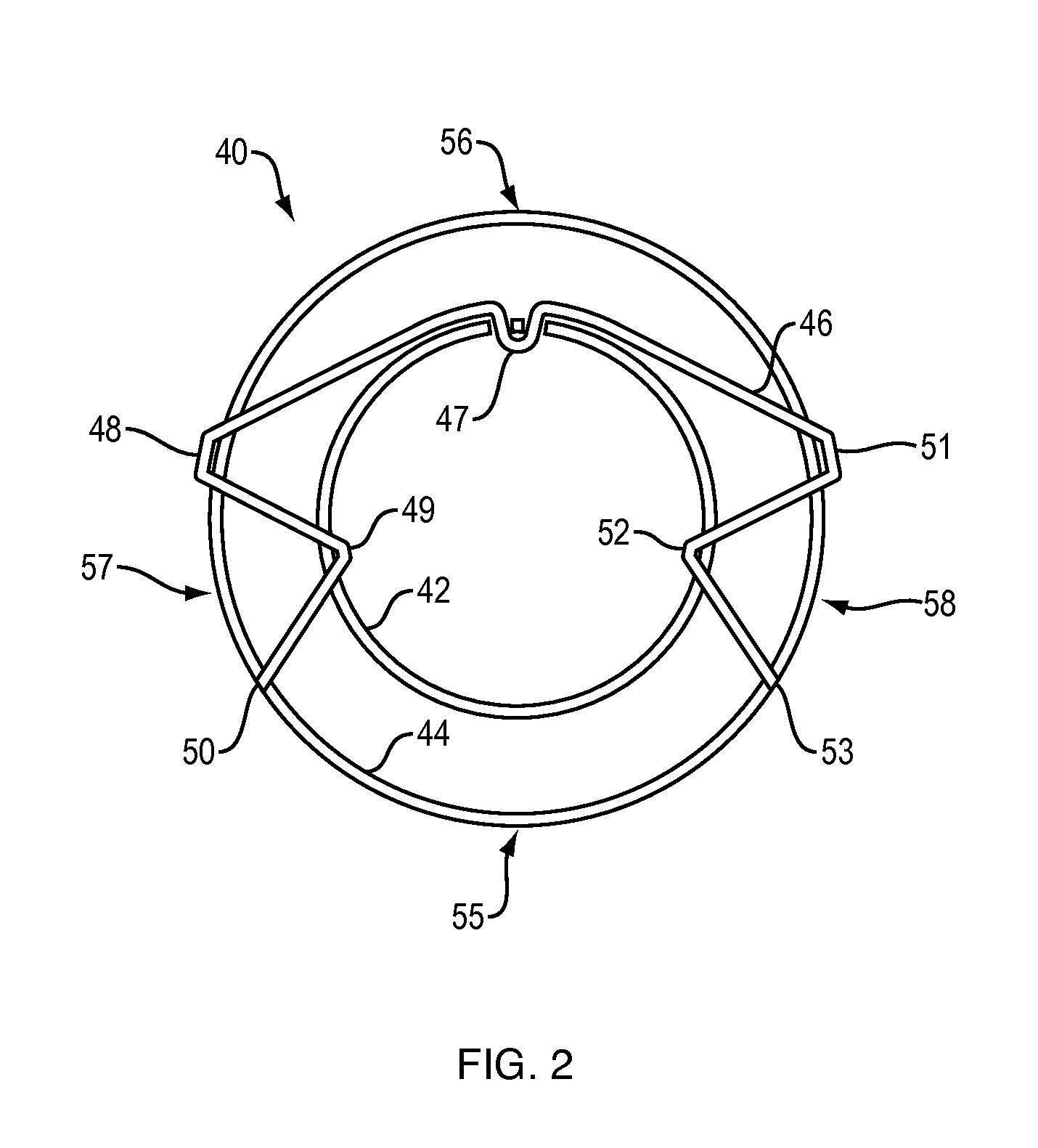
FIG. 2 is a similar view of an alternative arrangement of a personal impact protection device.
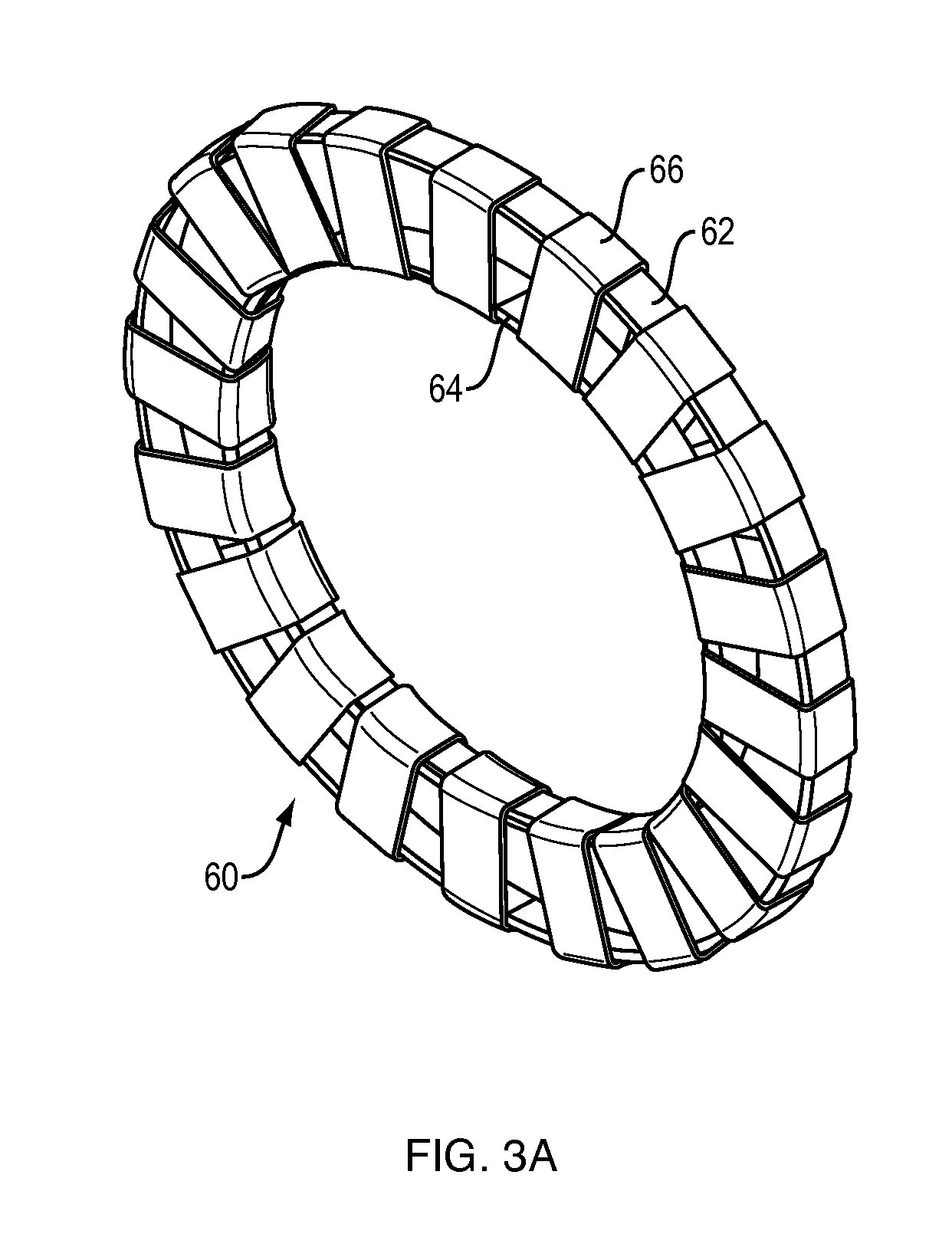
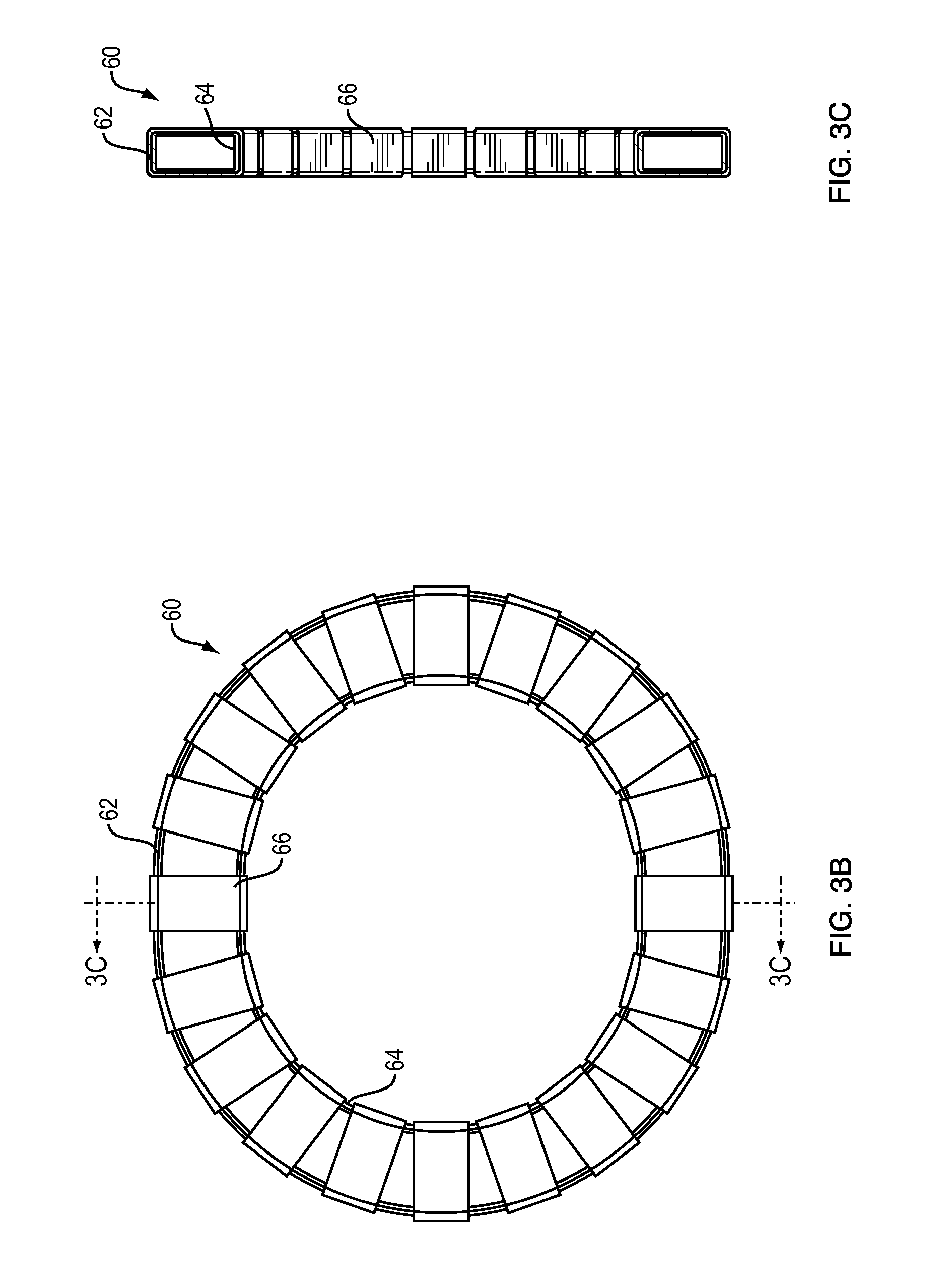
FIGS. 3A and 3B are perspective and top views, respectively, of an energy-absorption subassembly for a personal impact protection device, and FIG. 3C is a cross-sectional view taken along line A-A of FIG. 3B.
FIG. 4 is a highly schematic representation of a helmet worn on the head to protect the head.
FIGS. 5A and 5B are schematic side views of the helmet of FIG. 4 in the at-rest and under-impact positions, respectively.
FIGS. 6A, 6B, 6C and 6D are perspective, side, front, and a second perspective view, respectively, of an impact protection device for protection of a knee.
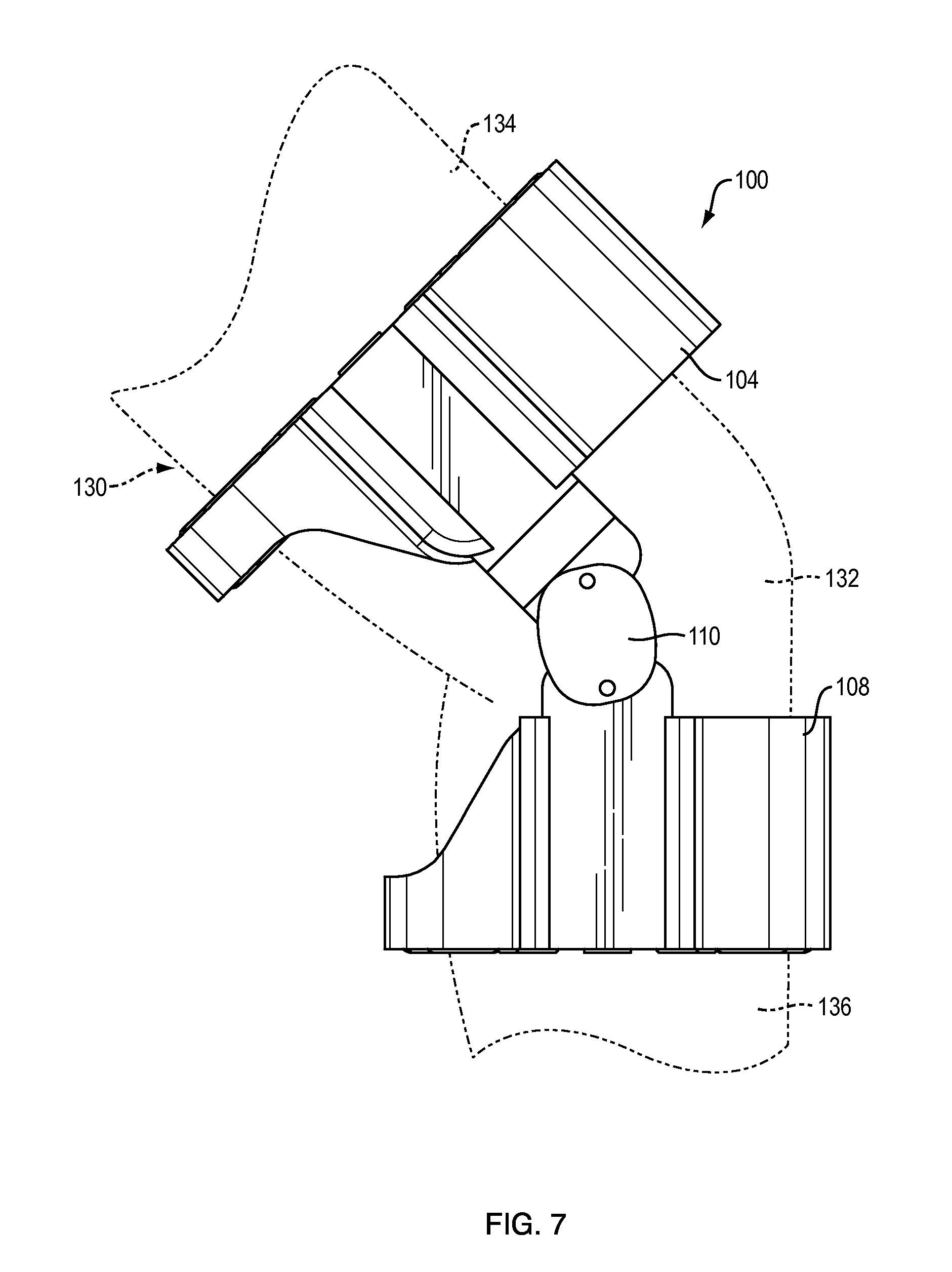
FIG. 7 shows the device of FIG. 6 in use.
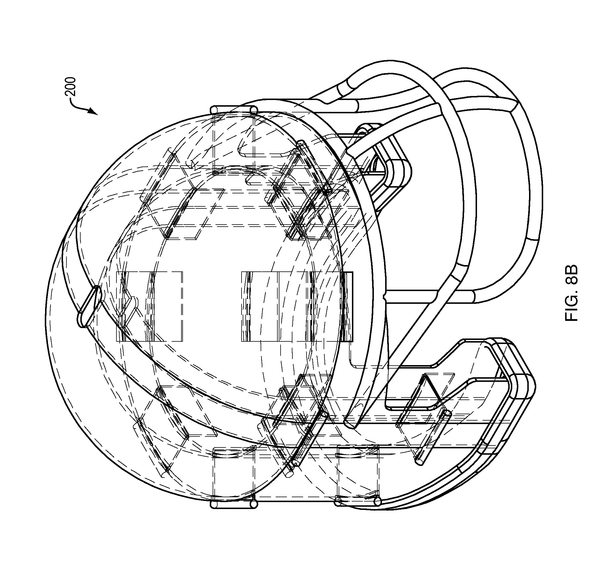
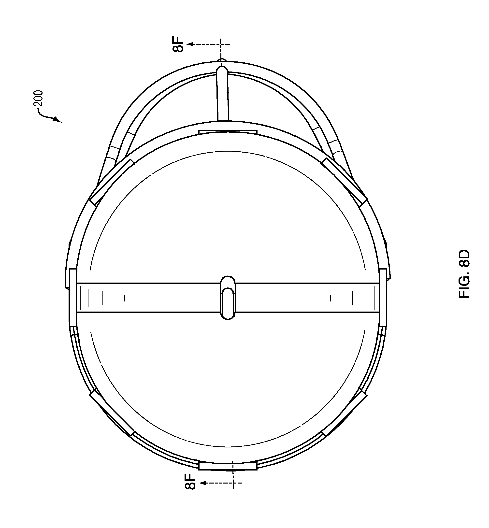
FIGS. 8A-8F are full perspective, hidden-detail perspective, side, top and two cross-sectional views, respectively, of a different helmet design.
FIG. 9 is a schematic cross-sectional view of a different helmet design.
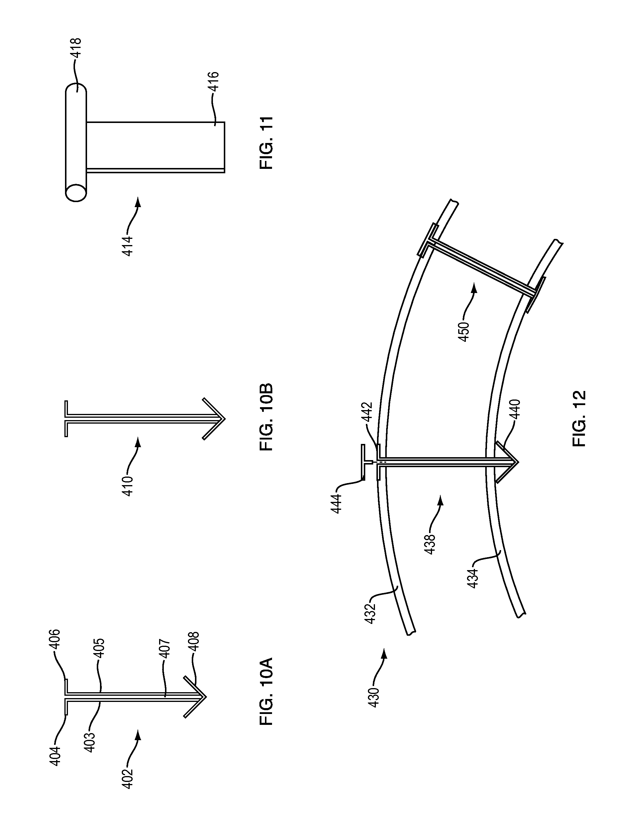
FIGS. 10A and 10B are side views of two alternative energy absorption members.
FIG. 11 shows a tool that can be used to insert the members shown in FIGS. 10A and 10B.
FIG. 12 is a partial cross sectional view of a protective device using the energy absorption members of FIGS. 10A and 10B.
FIG. 13A is a partial cross-sectional view of another impact protection device.
FIG. 13B is an end view of a portion of FIG. 13A.
FIG. 13C is a cross-sectional view taken along line A-A of FIG. 13A.
DESCRIPTION OF EMBODIMENTS
The advance set forth in this disclosure may be accomplished in a personal impact protection device. The personal impact protection device uses one or more elastomeric energy-absorption members that are mechanically coupled to two spaced nested mechanical members that act as impact areas, and also act as anchor points and supports for the elastomeric members. One of the two mechanical members is coupled to a person's body. The coupling can be to clothing worn by the person or directly to the body of the person. The coupling can be accomplished by means such as elastic straps. When the impact protection device undergoes impact to the second or outer member, the second mechanical member (that is not coupled to the body) is moved relative to the first mechanical member. This movement causes the spacing between the members to change: on the side of the members away from the impact, the spacing between the members increases. This causes the elastomeric members located in the region in which the spacing has increased to stretch. As the elastomeric members stretch, they absorb momentum and thus lower the force felt by the person wearing the device. The impact protection device thus helps to protect the person from injury caused by the impact.
Personal impact protection device 10 is schematically depicted in FIGS. 1A and 1B. Device 10 includes outer mechanical member or shell 12 that substantially or fully surrounds, and is spaced from, inner mechanical member or shell 14. The shells are preferably nested together and they may or may not be concentric. Shells 12 and 14 are sized and shaped and made from a material that is sufficient for the intended application of device 10. Different applications are described below. Typically, shells 12 and 14 are made from a molded plastic material such as polycarbonate. Device 10 includes one or more elastomeric energy absorption members. In this example, one member 16 provides the compliance and energy absorption functions. Member 16 in this case is a thin, flat piece of elastomeric material that may take the form of a strap or sheet of material. One material may be butyl rubber. Other materials, sizes, shapes and thicknesses are contemplated depending on the overall construction of the impact protection device, the arrangement of and distances between the first and second mechanical members, and the amount of force and the locations and directions of impact that are designed to be ameliorated by the device.
Energy-absorption member 16 is anchored to shell 12 at locations 21 and 22 and anchored to shell 14 at location 20. Upon inwardly-directed impact against shell 12 at or proximate location 26, shell 12 is pushed in the direction of arrow "A" relative to shell 14, which is stationary or largely stationary due to it being coupled to clothing or the body. The impact thus increases the distance between the shells at the side opposite the impact location, indicated by increased gap 30. This motion causes member 16 to stretch, which absorbs energy. In an ideal situation, all of the impact energy is absorbed by member 16. Even if less than all of the energy is absorbed, the energy absorption decreases the amount of energy transferred to the body in and around area 27 proximate the area of impact 26.
The personal impact protection device can be constructed and arranged to absorb impact energy from all directions and angles, or from less than all. The example shown in FIGS. 1A and 1B would do little to absorb impact energy from direction 29 or another direction in which energy-absorption members are folded or compressed as opposed to being stretched, as the elastomeric energy-absorption members will simply bend or fold if they are compressed. This property of relatively thin and elongated elastomeric members can be ameliorated by arranging the one or more energy-absorption members such that they are stretched when the impact protection device is impacted in a particular location and/or direction. As one simple example, FIG. 2 depicts a personal impact protection device 40 that will absorb energy from impact around the entire circumference of outer member or shell 44. For impacts at the front area 56, rear area 55 and the lateral areas 57 and 58, elastomeric energy absorption member 46 will be stretched and thus absorb energy. This is accomplished by anchoring single elastomeric member 46 at points 47-53 to both the inner mechanical member or shell 42 and the outer mechanical member or shell 44. The same function could be accomplished with a plurality of elastomeric energy-absorption members that are mechanically coupled to both the inner and outer shells and located at locations in which the outer shell will be pushed away from the inner shell upon impact: in other words, in locations other than at the impact or expected impact location. Obviously if impact can be expected at any point around the circumference of the impact protection device, elastomeric energy-absorption members should be spaced around at least most of or all of the circumferences of the inner and outer shells. Other energy absorption means such as traditional compressible cushioning (not shown), can potentially be added, to augment the elastomeric-based energy absorption by locating the cushioning between the energy absorption members at the expected impact areas.
The personal impact protection device may include one or more energy-absorption subassemblies. Broadly, an energy-absorption subassembly can be an assembly that carries one or more elastomeric energy-absorption members and that is constructed and arranged to be mechanically coupled to and located between the first and second mechanical members or shells. The energy-absorption subassemblies thus can assist with the ease of manufacturing or assembly of the personal impact protection device.
In a non-limiting embodiment shown in FIGS. 3A-3C, energy-absorption subassembly 60 comprises generally concentric spaced annular rings comprising an inner ring 64 and an outer ring 62. A plurality of energy-absorption members 66 are mechanically coupled to both the inner and outer ring and span the distance between the rings. In this example, members 66 are annular pieces of elastomeric material. Members 66 can be created, for example, through extrusion, or by cutting an elastomeric tube of the correct diameter into pieces of a desired width. Members 66 can be anchored to the rings or not, can be a desired thickness and width and/or material, and can be located at desired locations and spaced in a desired manner to accomplish a particular amount of energy-absorption at one or more desired locations of the subassembly. For example, stronger elastomers can be placed with some slack such that they begin to stretch only close to the endpoint of travel of the outer ring (or the outer mechanical assembly); this would be useful for heavy impacts that otherwise would cause the rings (or mechanical members) to come into contact and thus prevent further energy absorption. Multiple elastomeric members of different lengths and/or different strengths can be located in parallel so that their energy-absorption is cumulative.
The subassembly can be mechanically coupled to the mechanical members/shells in a desired fashion, such as by riveting or using other fasteners. Typically, outer ring 62 would be fixed into the inside of the outer shell, and inner ring 64 would be fixed to the outside of the inner shell. Subassembly 60 thus would establish the gap between the inner and outer mechanical members/shells.
The circular subassembly is not necessary. A similar result can be accomplished by using a number of smaller subassemblies each comprising spaced structural members that are adapted to support one or more elastomers, e.g., with one or two elastomers to each subassembly. The subassemblies can be arc-shaped, or can take another shape that is appropriate for the space between shells in which they are to be located. They can be distributed anywhere in the helmet or other personal impact protection device. They can be attached to any helmet of any size using standard mechanical fasteners such as rivets. The elastomer is tubular, like a piece of a bicycle inner tube. The tubes slip over the structural members of the subassembly, and the subassemblies are then attached to each shell. The absorption strength of a subassembly can be changed simply by using a longer tube. The distance between the shells can be any length, say from 1 to 3 inches, using standard parts. A three inch elastomer has nine times the absorption of a 1 one inch elastomer. More generally, subassembly 60 can be divided into individual subassemblies as may be desirable to achieve a particular result.
One particular embodiment of the personal impact protection device is a helmet that is constructed and arranged to be worn on the head of a user to protect the head from impact injury. Helmet 70, FIGS. 4 and 5, comprises first or inner shell 72 that is constructed and adapted to be placed on head 76. This placement anchors shell 72, ideally such that it does not move, or at least is constrained from movement in six degrees of freedom. Outer shell 74 is spaced from and substantially surrounds inner shell 72. In this example, two energy-absorption subassemblies 80 and 82 are located in the space between shells 72 and 74. Subassemblies 80 and 82 generally have the same construction as subassembly 60, FIG. 3. If subassembly 80 is located in the helmet around the forehead region, where the helmet encircles the head, it can be fully annular and can have elastomeric energy-absorption members around its entire periphery. Since second subassembly 82 is located in a region of the helmet that has an opening in front of the face, it is not fully annular but is more arc-shaped, encompassing an angle of around 180 to 270 degrees. Face mask 78 is mechanically coupled to outer shell 74, so that forces on the facemask are transferred to the outer shell and thus cause its motion, which results in forces being dispersed.
The operation of helmet 70 is schematically depicted in FIGS. 5A and 5B. FIG. 5A shows a rest position in which there is no impact on the helmet. FIG. 5B shows an impact 84 on the left side of helmet 70. The impact pushes shell 74 to the left, in other words, parallel to the direction of the impact. Since shell 72 is fixed to the head, it does not substantially move. The result is that gap 86 is increased, which stretches all of the elastomeric members of both subassemblies 80 and 82 that are on the right-hand side of the subassemblies, and to some extent, elastomeric members located at the front and rear of the helmet. This absorbs impact energy. Elastomeric members in the area of impact are folded or compressed as indicated by members 91 and 92; these contribute little or nothing to energy absorption.
Helmet 70 is also able to absorb blows borne from the bottom or top, and oblique blows that cause torque. Any impact that moves the outer ring of an energy-absorption subassembly relative to the inner ring will cause one or more elastomeric members to stretch, and thus absorb energy. Any motion of the outer shell that causes the stretching in any direction of one or more elastomeric members will absorb energy and thus help to ameliorate the effects of impact.
A specific embodiment of an impact protection device for protection of a knee, is shown in FIGS. 6 and 7. Device 100 in this case comprises two energy absorption subassemblies 102 and 106. Each such subassembly is mechanically coupled to one of housings 104 and 108. The housings are interconnected by a pivot or hinge device 110 that allows housings 104 and 108 to pivot about one or more axes that are normal to the surface of hinge 110. Also, plates 153 and 155 that are directly coupled to hinge 100 are adapted to slide up and down within receiving channels 154 and 156, respectively, to give housings 104 and 108 the ability to move vertically; this allows for adjustment for comfort and fit, and also allows for greater freedom of movement of the user. In use as shown in FIG. 7, pivot 110 is placed proximate knee area 132 of leg 130. Hinge 100 could be covered by a protective cover or disk (not shown) to help prevent it from being damaged by impacts. Housing 104 is located above the knee, in thigh area 134. Housing 108 is located below the knee, in calf area 136. Device 100 is designed to help absorb the energy of impacts to the outside of the knee.
Device 100 is worn such that the side with the pivot and that defines a continuous portion of hinged housing assembly 112 is located along the outside as opposed to the inside of the wearer's knee, where impact is most likely to occur in a sport such as football. The housing assembly helps to transfer force at any location along the length of the assembly to one or both of the energy-absorption subassemblies 102 and 106. Assemblies 102 and 106 are arranged such that in the rest position shown in the drawings, there is a larger gap between the inner and outer rings on this outside area proximate portion 120 than on the opposite or inside portion 121. Since the gap in the area of impact defines the maximum travel of the outer ring of the energy-absorption subassembly relative to the inner ring, having the inner and outer rings generally but not exactly concentric as in this case, can provide additional energy absorption in one direction, which in this case is impact to the outside of the knee area that can cause severe injury.
Housing 104 can pivot about axis 113. Housing 108 can pivot about axis 114. Structure 110 can pivot about axes 113 and 114. Elastomeric energy-absorption member 103 of subassembly 102 and elastomeric energy-absorption member 107 of energy absorption subassembly 106 are indicated in the drawings.
FIGS. 8A-8F show an alternative helmet design, and illustrates features that can be applied to helmets and other impact protection devices according to this disclosure. Helmet 200 comprises inner shell 204 that sits on the head and surrounding spaced outer shell 202. Facemask 206 is mounted to outer shell 202. Energy-absorption subassemblies 201 and 203 in this case each comprise a plurality of separate elastomeric members that are anchored in both shells, such as members 222 and 232, and as shown in FIG. 8F members 251-255 of subassembly 201, and members 261-263 of subassembly 203.
In this non-limiting example, each elastomeric member is a flat sheet that fits through slots in both shells. Each has one enlarged end (e.g., ends 220 and 230) that sits on either the outside of the outer shell or the inside of the inner shell to prevent the member from being pulled through the adjacent slot. The other ends of the elastomeric members are mechanically coupled to the other shell by a suitable mechanical means, such as clamps 224 and 234. Also, additional molded rubber or plastic part 208 (with sufficient compliance such that it does not substantially inhibit relative motion of the shells) is coupled to the lower rims of the two shells. Part 208 can potentially add some additional compliance/energy absorption, but mainly part 208 is used to close the opening between the shells to prevent clothing or other objects from entering.
FIGS. 10A and 10B show two similar energy absorption members 402 and 410. Differences between the two can be their length and/or their strength. Member 402 illustrates the construction with parallel legs 403 and 405 that have perpendicular terminal portions 404 and 406 and distal terminal portion 408. Members 402 and 410 can be coupled to two spaced shells such as shells 432 and 434 of impact protection device 430, FIG. 12. The members are pushed through aligned openings in the shells via tool 414, FIG. 11, which includes blade 416 that is sized and shaped to fit into opening 407 between legs 403 and 405. The handle 418 is pushed down to force enlarged end 408 through a hole in the inner shell. Upper ends 404 and 406 sit against the outer shell adjacent to the opening. This anchors the member to both shells. As shown in FIG. 12, enlarged common end 440 of member 438 will sit against the inside of inner shell 434 while end 442 sits in a recess on the outside of outer shell 432. Cap 444 can be pushed into the recess to smooth the outside of device 430. Member 450 is slightly longer than member 438 so it is slack in the at-rest, non-impacted position depicted in FIG. 12. Upon impact, member 438 will be stretched and then eventually if the shells are moved sufficiently far apart member 450 can be stretched to absorb more energy. Also, as described above, the different members can be different strengths (e.g., different thicknesses) to provide more variability to the energy absorption characteristics of the protective device.
Another example is shown in FIGS. 13A-13C. Impact protection device 500 includes outer shell 502 and inner shell 504. Elastomeric spring 510 connects the shells. Spring 510 is a continuous thin elastomeric sheet with ends 561 and 562. End 562 is fixed to shell 504 while end 561 is free. Spring 510 is threaded over rollers 511, 513, 515, 519 and 521 that are carried by outer shell 502, and rollers 512, 514, 518 and 520 that are carried by inner shell 514. The rollers allow the spring to move relative to the shells. One roller 512 is shown in FIG. 13C; the roller can move within retainers 530 and 531 that are fastened to the shell. Other mechanical means of carrying rollers or equivalent structures over which the spring can move (such as a low-friction stationary surface) are also contemplated herein.
Device 500 further includes mechanism 524 that allows for adjustment of the tension "T" on spring 510. In this non-limiting example this is accomplished with nip rollers 515 and 516, FIGS. 13A and 13B, through which elastomer 510 passes. The nip rollers grip the elastomer to hold it in place under normal loads expected under normal impacts that are expected. Rollers 515 and 516 are coupled such that they move in unison and in opposite directions, in this case with meshed gears 545 and 546 that are each coupled to one of the rollers. This allows one roller to be turned to tighten or loosened the spring as a means to adjust the spring preload tension. A ratchet consisting of toothed wheel 545 that is coupled to one of the nip rollers, along with pawl 546, inhibits the elastomer from being pulled back through the nip rollers when impact on the outer shell occurs. End 551 of roller 515 is configured (e.g., with a hex nut) such that a torque wrench can be coupled to it, so that the pretension can be set as desired. This will allow the device to be calibrated to an initial preload force.
Pre-tensioning of the elastomer(s) helps to ensure that all shell motion occurring on impact results in stretching of the elastomer(s) (spring(s)) and absorption of impact energy. A second or more additional elastomers can be added in parallel with spring 510. This can have a higher or lower spring constant and can be pre-tensioned as desired. The multiple springs can be selected and tensioned to achieve a desired blended energy absorption result. For example, a second elastomer could have a higher spring constant and set such that it was stretched under greater impacts, to provide more damping during higher impact events.
Another option, not shown in the drawings, would be to include a circuit that recorded the number of impacts to the device that exceeded the energy-absorption capacity. This could be accomplished by including a network of conductors on the outside of the inner shell and on the inside of the outer shell, arranged such that electrical contact occurred between the two networks when the shells touched (which would happen when the energy absorption members were taxed beyond their capacity). A simple circuit would be included to both measure continuity and record the data; the circuit would likely include a battery and a controller with memory. The conductors could be accomplished with thin copper strips similar to ribbon cables, or other conductors. The conductors could be arranged in a criss-cross or hatched pattern such that electrical contact was made when the shells touched even if the alignment between the shells changed due to oblique blows that twisted the outer shell, and the like.
* * * * *
D00000
D00001
D00002
D00003
D00004
D00005
D00006
D00007
D00008
D00009
D00010
D00011
D00012
D00013

D00014
D00015

D00016

D00017

D00018
D00019

XML
uspto.report is an independent third-party trademark research tool that is not affiliated, endorsed, or sponsored by the United States Patent and Trademark Office (USPTO) or any other governmental organization. The information provided by uspto.report is based on publicly available data at the time of writing and is intended for informational purposes only.
While we strive to provide accurate and up-to-date information, we do not guarantee the accuracy, completeness, reliability, or suitability of the information displayed on this site. The use of this site is at your own risk. Any reliance you place on such information is therefore strictly at your own risk.
All official trademark data, including owner information, should be verified by visiting the official USPTO website at www.uspto.gov. This site is not intended to replace professional legal advice and should not be used as a substitute for consulting with a legal professional who is knowledgeable about trademark law.