Miniaturized highly-efficient designs for near-field power transfer system
Hosseini , et al.
U.S. patent number 10,320,446 [Application Number 15/269,729] was granted by the patent office on 2019-06-11 for miniaturized highly-efficient designs for near-field power transfer system. This patent grant is currently assigned to Energous Corporation. The grantee listed for this patent is ENERGOUS CORPORATION. Invention is credited to Alister Hosseini, Michael A. Leabman.


View All Diagrams
| United States Patent | 10,320,446 |
| Hosseini , et al. | June 11, 2019 |
Miniaturized highly-efficient designs for near-field power transfer system
Abstract
Near-field power transfer systems can include antenna elements that constructed or printed close to each other in a meandered arrangement, where neighboring antenna elements conduct currents that flow in opposite directions. This current flow entirely or almost entirely cancels out any far field RF radiation generated by the antennas or otherwise generated by the electromagnetic effects of the current flow. For a first current flowing in a first path, there may be a second current flowing in a second cancellation path, which cancels the far field radiation produced by the first current flowing in the first path. Therefore, there may be no radiation of power to the far field. Such cancellation, may not occur in a near-field active zone, where the transfer of power may occur between the transmitter and the receiver. A ground plane may block the leakage of power from the back of a transmitter and/or a receiver.
| Inventors: | Hosseini; Alister (Long Beach, CA), Leabman; Michael A. (San Ramon, CA) | ||||||||||
|---|---|---|---|---|---|---|---|---|---|---|---|
| Applicant: |
|
||||||||||
| Assignee: | Energous Corporation (San Jose,
CA) |
||||||||||
| Family ID: | 59086880 | ||||||||||
| Appl. No.: | 15/269,729 | ||||||||||
| Filed: | September 19, 2016 |
Prior Publication Data
| Document Identifier | Publication Date | |
|---|---|---|
| US 20170187422 A1 | Jun 29, 2017 | |
Related U.S. Patent Documents
| Application Number | Filing Date | Patent Number | Issue Date | ||
|---|---|---|---|---|---|
| 15046348 | Feb 17, 2016 | 10027158 | |||
| 62374578 | Aug 12, 2016 | ||||
| 62387205 | Dec 24, 2015 | ||||
| Current U.S. Class: | 1/1 |
| Current CPC Class: | H04B 5/005 (20130101); H02J 50/27 (20160201); H02J 50/23 (20160201); H02J 50/005 (20200101); H04B 5/0037 (20130101); H01F 38/14 (20130101); H01F 27/2804 (20130101) |
| Current International Class: | H04B 5/00 (20060101); H02J 50/23 (20160101); H02J 50/27 (20160101) |
| Field of Search: | ;320/107-115 |
References Cited [Referenced By]
U.S. Patent Documents
| 787412 | April 1905 | Tesla |
| 3167775 | January 1965 | Guertler |
| 3434678 | March 1969 | Brown et al. |
| 3696384 | October 1972 | Lester |
| 3754269 | August 1973 | Clavin |
| 4101895 | July 1978 | Jones, Jr. |
| 4360741 | November 1982 | Fitzsimmons et al. |
| 4944036 | July 1990 | Hyatt |
| 4995010 | February 1991 | Knight |
| 5200759 | April 1993 | McGinnis |
| 5211471 | May 1993 | Rohrs |
| 5548292 | August 1996 | Hirshfield et al. |
| 5556749 | September 1996 | Mitsuhashi et al. |
| 5568088 | October 1996 | Dent et al. |
| 5646633 | July 1997 | Dahlberg |
| 5697063 | December 1997 | Kishigami et al. |
| 5712642 | January 1998 | Hulderman |
| 5936527 | August 1999 | Isaacman et al. |
| 5982139 | November 1999 | Parise |
| 6046708 | April 2000 | MacDonald, Jr. et al. |
| 6127799 | October 2000 | Krishnan |
| 6127942 | October 2000 | Welle |
| 6163296 | December 2000 | Lier et al. |
| 6289237 | September 2001 | Mickle et al. |
| 6329908 | December 2001 | Frecska |
| 6421235 | July 2002 | Ditzik |
| 6437685 | August 2002 | Hanaki |
| 6456253 | September 2002 | Rummeli et al. |
| 6476795 | November 2002 | Derocher et al. |
| 6501414 | December 2002 | Amdt et al. |
| 6583723 | June 2003 | Watanabe et al. |
| 6597897 | July 2003 | Tang |
| 6615074 | September 2003 | Mickle et al. |
| 6650376 | November 2003 | Obitsu |
| 6664920 | December 2003 | Mott et al. |
| 6798716 | September 2004 | Charych |
| 6803744 | October 2004 | Sabo |
| 6853197 | February 2005 | McFarland |
| 6856291 | February 2005 | Mickle et al. |
| 6911945 | June 2005 | Korva |
| 6960968 | November 2005 | Odendaal et al. |
| 6967462 | November 2005 | Landis |
| 6988026 | January 2006 | Breed et al. |
| 7003350 | February 2006 | Denker et al. |
| 7027311 | April 2006 | Vanderelli et al. |
| 7068234 | June 2006 | Sievenpiper |
| 7068991 | June 2006 | Parise |
| 7183748 | February 2007 | Unno et al. |
| 7191013 | March 2007 | Miranda et al. |
| 7196663 | March 2007 | Bolzer et al. |
| 7205749 | April 2007 | Hagen et al. |
| 7222356 | May 2007 | Yonezawa et al. |
| 7274334 | September 2007 | o'Riordan et al. |
| 7274336 | September 2007 | Carson |
| 7351975 | April 2008 | Brady et al. |
| 7359730 | April 2008 | Dennis et al. |
| 7392068 | June 2008 | Dayan |
| 7403803 | July 2008 | Mickle et al. |
| 7443057 | October 2008 | Nunally |
| 7451839 | November 2008 | Perlman |
| 7463201 | December 2008 | Chiang et al. |
| 7471247 | December 2008 | Saily |
| 7535195 | May 2009 | Horovitz et al. |
| 7614556 | November 2009 | Overhultz et al. |
| 7639994 | December 2009 | Greene et al. |
| 7643312 | January 2010 | Vanderelli et al. |
| 7652577 | January 2010 | Madhow et al. |
| 7679576 | March 2010 | Riedel et al. |
| 7702771 | April 2010 | Ewing et al. |
| 7786419 | August 2010 | Hyde et al. |
| 7812771 | October 2010 | Greene et al. |
| 7830312 | November 2010 | Choudhury et al. |
| 7844306 | November 2010 | Shearer et al. |
| 7868482 | January 2011 | Greene et al. |
| 7898105 | March 2011 | Greene et al. |
| 7904117 | March 2011 | Doan et al. |
| 7911386 | March 2011 | Ito et al. |
| 7925308 | April 2011 | Greene et al. |
| 7948208 | May 2011 | Partovi et al. |
| 8055003 | November 2011 | Mittleman et al. |
| 8070595 | December 2011 | Alderucci et al. |
| 8072380 | December 2011 | Crouch |
| 8092301 | January 2012 | Alderucci et al. |
| 8099140 | January 2012 | Arai |
| 8115448 | February 2012 | John |
| 8159090 | April 2012 | Greene et al. |
| 8159364 | April 2012 | Zeine |
| 8180286 | May 2012 | Yamasuge |
| 8228194 | July 2012 | Mickle |
| 8234509 | July 2012 | Gioscia et al. |
| 8264101 | September 2012 | Hyde et al. |
| 8264291 | September 2012 | Morita |
| 8276325 | October 2012 | Clifton et al. |
| 8278784 | October 2012 | Cook et al. |
| 8284101 | October 2012 | Fusco |
| 8310201 | November 2012 | Wright |
| 8338991 | December 2012 | Von Novak et al. |
| 8362745 | January 2013 | Tinaphong |
| 8380255 | February 2013 | Shearer et al. |
| 8410953 | April 2013 | Zeine |
| 8411963 | April 2013 | Luff |
| 8432062 | April 2013 | Greene et al. |
| 8432071 | April 2013 | Huang et al. |
| 8446248 | May 2013 | Zeine |
| 8447234 | May 2013 | Cook et al. |
| 8451189 | May 2013 | Fluhler |
| 8452235 | May 2013 | Kirby et al. |
| 8457656 | June 2013 | Perkins et al. |
| 8461817 | June 2013 | Martin et al. |
| 8467733 | June 2013 | Leabman |
| 8497601 | July 2013 | Hall et al. |
| 8497658 | July 2013 | Von Novak et al. |
| 8552597 | August 2013 | Song et al. |
| 8558661 | October 2013 | Zeine |
| 8560026 | October 2013 | Chanterac |
| 8604746 | December 2013 | Lee |
| 8614643 | December 2013 | Leabman |
| 8621245 | December 2013 | Shearer et al. |
| 8626249 | January 2014 | Kuusilinna et al. |
| 8629576 | January 2014 | Levine |
| 8653966 | February 2014 | Rao et al. |
| 8674551 | March 2014 | Low et al. |
| 8686685 | April 2014 | Moshfeghi |
| 8712355 | April 2014 | Black et al. |
| 8712485 | April 2014 | Tam |
| 8718773 | May 2014 | Wills et al. |
| 8729737 | May 2014 | Schatz et al. |
| 8736228 | May 2014 | Freed et al. |
| 8760113 | June 2014 | Keating |
| 8770482 | July 2014 | Ackermann et al. |
| 8772960 | July 2014 | Yoshida |
| 8823319 | September 2014 | Von Novak, III et al. |
| 8832646 | September 2014 | Wendling |
| 8854176 | October 2014 | Zeine |
| 8860364 | October 2014 | Low et al. |
| 8897770 | November 2014 | Frolov et al. |
| 8903456 | December 2014 | Chu et al. |
| 8917057 | December 2014 | Hui |
| 8923189 | December 2014 | Leabman |
| 8928544 | January 2015 | Massie et al. |
| 8937408 | January 2015 | Ganem et al. |
| 8946940 | February 2015 | Kim et al. |
| 8963486 | February 2015 | Kirby et al. |
| 8970070 | March 2015 | Sada et al. |
| 8989053 | March 2015 | Skaaksrud et al. |
| 9000616 | April 2015 | Greene et al. |
| 9001622 | April 2015 | Perry |
| 9006934 | April 2015 | Kozakai et al. |
| 9021277 | April 2015 | Shearer et al. |
| 9030161 | May 2015 | Lu et al. |
| 9059598 | June 2015 | Kang et al. |
| 9059599 | June 2015 | Won et al. |
| 9077188 | July 2015 | Moshfeghi |
| 9083595 | July 2015 | Rakib et al. |
| 9088216 | July 2015 | Garrity et al. |
| 9124125 | September 2015 | Leabman et al. |
| 9130397 | September 2015 | Leabman et al. |
| 9130602 | September 2015 | Cook |
| 9142998 | September 2015 | Yu et al. |
| 9143000 | September 2015 | Leabman et al. |
| 9143010 | September 2015 | Urano |
| 9178389 | November 2015 | Hwang |
| 9225196 | December 2015 | Huang et al. |
| 9240469 | January 2016 | Sun et al. |
| 9242411 | January 2016 | Kritchman et al. |
| 9244500 | January 2016 | Cain et al. |
| 9252628 | February 2016 | Leabman et al. |
| 9270344 | February 2016 | Rosenberg |
| 9282582 | March 2016 | Dunsbergen et al. |
| 9294840 | March 2016 | Anderson et al. |
| 9297896 | March 2016 | Andrews |
| 9318898 | April 2016 | John |
| 9368020 | June 2016 | Bell et al. |
| 9401977 | July 2016 | Gaw |
| 9409490 | August 2016 | Kawashima |
| 9438045 | September 2016 | Leabman |
| 9438046 | September 2016 | Leabman |
| 9444283 | September 2016 | Son et al. |
| 9450449 | September 2016 | Leabman et al. |
| 9461502 | October 2016 | Lee et al. |
| 9520725 | December 2016 | Masaoka et al. |
| 9520748 | December 2016 | Hyde et al. |
| 9522270 | December 2016 | Perryman et al. |
| 9537354 | January 2017 | Bell et al. |
| 9537357 | January 2017 | Leabman |
| 9537358 | January 2017 | Leabman |
| 9538382 | January 2017 | Bell et al. |
| 9544640 | January 2017 | Lau |
| 9559553 | January 2017 | Bae |
| 9564773 | February 2017 | Pogorelik et al. |
| 9571974 | February 2017 | Choi et al. |
| 9590317 | March 2017 | Zimmerman et al. |
| 9590444 | March 2017 | Walley |
| 9620996 | April 2017 | Zeine |
| 9647328 | May 2017 | Dobric |
| 9706137 | July 2017 | Scanlon et al. |
| 9711999 | July 2017 | Hietala et al. |
| 9723635 | August 2017 | Nambord et al. |
| 9793758 | October 2017 | Leabman |
| 9793764 | October 2017 | Perry |
| 9800172 | October 2017 | Leabman |
| 9806564 | October 2017 | Leabman |
| 9819230 | November 2017 | Petras et al. |
| 9853361 | December 2017 | Chen et al. |
| 9866279 | January 2018 | Bell et al. |
| 9876394 | January 2018 | Leabman |
| 2001/0027876 | October 2001 | Tsukamoto et al. |
| 2002/0001307 | January 2002 | Nguyen et al. |
| 2002/0024471 | February 2002 | Ishitobi |
| 2002/0028655 | March 2002 | Rosener et al. |
| 2002/0034958 | March 2002 | Oberschmidt et al. |
| 2002/0054330 | May 2002 | Jinbo et al. |
| 2002/0065052 | May 2002 | Pande et al. |
| 2002/0072784 | June 2002 | Sheppard et al. |
| 2002/0095980 | July 2002 | Breed et al. |
| 2002/0103447 | August 2002 | Terry |
| 2002/0133592 | September 2002 | Matsuda |
| 2002/0172223 | November 2002 | Stilp |
| 2003/0005759 | January 2003 | Breed et al. |
| 2003/0058187 | March 2003 | Billiet et al. |
| 2003/0076274 | April 2003 | Phelan et al. |
| 2003/0179152 | September 2003 | Watada et al. |
| 2003/0179573 | September 2003 | Chun |
| 2003/0192053 | October 2003 | Sheppard et al. |
| 2004/0019624 | January 2004 | Sukegawa |
| 2004/0020100 | February 2004 | O'Brien et al. |
| 2004/0036657 | February 2004 | Forster et al. |
| 2004/0066251 | April 2004 | Eleftheriades et al. |
| 2004/0107641 | June 2004 | Walton et al. |
| 2004/0113543 | June 2004 | Daniels |
| 2004/0119675 | June 2004 | Washio et al. |
| 2004/0130425 | July 2004 | Dayan et al. |
| 2004/0130442 | July 2004 | Breed |
| 2004/0142733 | July 2004 | Parise |
| 2004/0145342 | July 2004 | Lyon |
| 2004/0196190 | October 2004 | Mendolia et al. |
| 2004/0203979 | October 2004 | Attar et al. |
| 2004/0207559 | October 2004 | Milosavljevic |
| 2004/0218759 | November 2004 | Yacobi |
| 2004/0259604 | December 2004 | Mickle et al. |
| 2004/0263124 | December 2004 | Wieck et al. |
| 2005/0007276 | January 2005 | Barrick et al. |
| 2005/0030118 | February 2005 | Wang |
| 2005/0046584 | March 2005 | Breed |
| 2005/0055316 | March 2005 | Williams |
| 2005/0077872 | April 2005 | Single |
| 2005/0093766 | May 2005 | Turner |
| 2005/0116683 | June 2005 | Cheng |
| 2005/0117660 | June 2005 | Vialle et al. |
| 2005/0134517 | June 2005 | Gottl |
| 2005/0171411 | August 2005 | KenKnight |
| 2005/0198673 | September 2005 | Kit et al. |
| 2005/0227619 | October 2005 | Lee et al. |
| 2005/0232469 | October 2005 | Schofield |
| 2005/0237249 | October 2005 | Nagel |
| 2005/0237258 | October 2005 | Abramov et al. |
| 2005/0282591 | December 2005 | Shaff |
| 2006/0013335 | January 2006 | Leabman |
| 2006/0019712 | January 2006 | Choi |
| 2006/0030279 | February 2006 | Leabman et al. |
| 2006/0033674 | February 2006 | Essig, Jr. et al. |
| 2006/0071308 | April 2006 | Tang et al. |
| 2006/0092079 | May 2006 | de Rochemont |
| 2006/0094425 | May 2006 | Mickle et al. |
| 2006/0113955 | June 2006 | Nunally |
| 2006/0119532 | June 2006 | Yun et al. |
| 2006/0136004 | June 2006 | Cowan et al. |
| 2006/0160517 | July 2006 | Yoon |
| 2006/0183473 | August 2006 | Ukon |
| 2006/0190063 | August 2006 | Kanzius |
| 2006/0192913 | August 2006 | Shutou et al. |
| 2006/0199620 | September 2006 | Greene et al. |
| 2006/0238365 | October 2006 | Vecchione et al. |
| 2006/0266564 | November 2006 | Perlman et al. |
| 2006/0266917 | November 2006 | Baldis et al. |
| 2006/0278706 | December 2006 | Hatakayama et al. |
| 2006/0284593 | December 2006 | Nagy et al. |
| 2006/0287094 | December 2006 | Mahaffey et al. |
| 2007/0007821 | January 2007 | Rossetti |
| 2007/0019693 | January 2007 | Graham |
| 2007/0021140 | January 2007 | Keyes |
| 2007/0060185 | March 2007 | Simon et al. |
| 2007/0070490 | March 2007 | Tsunoda et al. |
| 2007/0090997 | April 2007 | Brown et al. |
| 2007/0093269 | April 2007 | Leabman et al. |
| 2007/0097653 | May 2007 | Gilliland et al. |
| 2007/0103110 | May 2007 | Sagoo |
| 2007/0106894 | May 2007 | Zhang |
| 2007/0109121 | May 2007 | Cohen |
| 2007/0139000 | June 2007 | Kozuma |
| 2007/0149162 | June 2007 | Greene et al. |
| 2007/0164868 | July 2007 | Deavours et al. |
| 2007/0173196 | July 2007 | Gallic |
| 2007/0173214 | July 2007 | Mickle et al. |
| 2007/0178857 | August 2007 | Greene et al. |
| 2007/0178945 | August 2007 | Cook et al. |
| 2007/0182367 | August 2007 | Partovi |
| 2007/0191074 | August 2007 | Harrist et al. |
| 2007/0191075 | August 2007 | Greene et al. |
| 2007/0197281 | August 2007 | Stronach |
| 2007/0210960 | September 2007 | Rofougaran et al. |
| 2007/0222681 | September 2007 | Greene et al. |
| 2007/0257634 | November 2007 | Leschin et al. |
| 2007/0273486 | November 2007 | Shiotsu |
| 2007/0296639 | December 2007 | Hook et al. |
| 2007/0298846 | December 2007 | Greene et al. |
| 2008/0014897 | January 2008 | Cook et al. |
| 2008/0024376 | January 2008 | Norris et al. |
| 2008/0048917 | February 2008 | Achour et al. |
| 2008/0062062 | March 2008 | Borau et al. |
| 2008/0062255 | March 2008 | Gal |
| 2008/0067874 | March 2008 | Tseng |
| 2008/0074324 | March 2008 | Puzella et al. |
| 2008/0089277 | April 2008 | Aledander et al. |
| 2008/0110263 | May 2008 | Klessel et al. |
| 2008/0113816 | May 2008 | Mahaffey et al. |
| 2008/0122297 | May 2008 | Arai |
| 2008/0123383 | May 2008 | Shionoiri |
| 2008/0129536 | June 2008 | Randall et al. |
| 2008/0140278 | June 2008 | Breed |
| 2008/0169910 | July 2008 | Greene et al. |
| 2008/0197802 | August 2008 | Onishi |
| 2008/0204342 | August 2008 | Kharadly |
| 2008/0204350 | August 2008 | Tam et al. |
| 2008/0210762 | September 2008 | Osada et al. |
| 2008/0211458 | September 2008 | Lawther et al. |
| 2008/0233890 | September 2008 | Baker |
| 2008/0248758 | October 2008 | Schedelbeck et al. |
| 2008/0248846 | October 2008 | Stronach et al. |
| 2008/0258993 | October 2008 | Gummalla et al. |
| 2008/0266191 | October 2008 | Hilgers |
| 2008/0278378 | November 2008 | Chang et al. |
| 2008/0309452 | December 2008 | Zeine |
| 2009/0002493 | January 2009 | Kates |
| 2009/0019183 | January 2009 | Wu et al. |
| 2009/0036065 | February 2009 | Siu |
| 2009/0047998 | February 2009 | Alberth, Jr. |
| 2009/0058354 | March 2009 | Harrison |
| 2009/0058361 | March 2009 | John |
| 2009/0058731 | March 2009 | Geary et al. |
| 2009/0067208 | March 2009 | Martin et al. |
| 2009/0096412 | April 2009 | Huang |
| 2009/0096413 | April 2009 | Partovi |
| 2009/0102292 | April 2009 | Cook et al. |
| 2009/0102296 | April 2009 | Greene et al. |
| 2009/0108679 | April 2009 | Porwal |
| 2009/0122847 | May 2009 | Nysen et al. |
| 2009/0128262 | May 2009 | Lee et al. |
| 2009/0157911 | June 2009 | Aihara |
| 2009/0200985 | August 2009 | Zane et al. |
| 2009/0206791 | August 2009 | Jung |
| 2009/0207090 | August 2009 | Pettus et al. |
| 2009/0207092 | August 2009 | Nysen et al. |
| 2009/0218884 | September 2009 | Soar |
| 2009/0218891 | September 2009 | McCollough |
| 2009/0219903 | September 2009 | Alamouti et al. |
| 2009/0243397 | October 2009 | Cook et al. |
| 2009/0264069 | October 2009 | Yamasuge |
| 2009/0280866 | November 2009 | Lo et al. |
| 2009/0281678 | November 2009 | Wakamatsu |
| 2009/0284082 | November 2009 | Mohammadian |
| 2009/0284083 | November 2009 | Karalis et al. |
| 2009/0284220 | November 2009 | Toncich et al. |
| 2009/0284227 | November 2009 | Mohammadian et al. |
| 2009/0284325 | November 2009 | Rossiter et al. |
| 2009/0286475 | November 2009 | Toncich et al. |
| 2009/0291634 | November 2009 | Saarisalo |
| 2009/0299175 | December 2009 | Bernstein et al. |
| 2009/0308936 | December 2009 | Nitzan et al. |
| 2009/0312046 | December 2009 | Clevenger et al. |
| 2009/0315412 | December 2009 | Yamamoto et al. |
| 2009/0322281 | December 2009 | Kamijo et al. |
| 2010/0001683 | January 2010 | Huang et al. |
| 2010/0007307 | January 2010 | Baarman et al. |
| 2010/0007569 | January 2010 | Sim et al. |
| 2010/0019686 | January 2010 | Gutierrez, Jr. |
| 2010/0019908 | January 2010 | Cho et al. |
| 2010/0026605 | February 2010 | Yang et al. |
| 2010/0027379 | February 2010 | Saulnier et al. |
| 2010/0029383 | February 2010 | Dai |
| 2010/0033021 | February 2010 | Bennett |
| 2010/0033390 | February 2010 | Alamouti et al. |
| 2010/0034238 | February 2010 | Bennett |
| 2010/0041453 | February 2010 | Grimm, Jr. |
| 2010/0044123 | February 2010 | Perlman et al. |
| 2010/0054200 | March 2010 | Tsai |
| 2010/0060534 | March 2010 | Oodachi |
| 2010/0066631 | March 2010 | Puzella et al. |
| 2010/0075607 | March 2010 | Hosoya |
| 2010/0079005 | April 2010 | Hyde et al. |
| 2010/0082193 | April 2010 | Chiappetta |
| 2010/0087227 | April 2010 | Francos et al. |
| 2010/0090524 | April 2010 | Obayashi |
| 2010/0090656 | April 2010 | Shearer et al. |
| 2010/0109443 | May 2010 | Cook et al. |
| 2010/0117926 | May 2010 | DeJean, II |
| 2010/0119234 | May 2010 | Suematsu et al. |
| 2010/0123618 | May 2010 | Martin et al. |
| 2010/0123624 | May 2010 | Minear et al. |
| 2010/0127660 | May 2010 | Cook et al. |
| 2010/0142418 | June 2010 | Nishioka et al. |
| 2010/0142509 | June 2010 | Zhu et al. |
| 2010/0148723 | June 2010 | Cook et al. |
| 2010/0151808 | June 2010 | Toncich et al. |
| 2010/0156721 | June 2010 | Alamouti et al. |
| 2010/0156741 | June 2010 | Vazquez et al. |
| 2010/0164296 | July 2010 | Kurs et al. |
| 2010/0164433 | July 2010 | Janefalker et al. |
| 2010/0171461 | July 2010 | Baarman et al. |
| 2010/0174629 | July 2010 | Taylor et al. |
| 2010/0176934 | July 2010 | Chou et al. |
| 2010/0181961 | July 2010 | Novak et al. |
| 2010/0181964 | July 2010 | Huggins et al. |
| 2010/0194206 | August 2010 | Burdo et al. |
| 2010/0201189 | August 2010 | Kirby et al. |
| 2010/0201201 | August 2010 | Mobarhan et al. |
| 2010/0201314 | August 2010 | Toncich et al. |
| 2010/0207572 | August 2010 | Kirby et al. |
| 2010/0210233 | August 2010 | Cook et al. |
| 2010/0213895 | August 2010 | Keating et al. |
| 2010/0214177 | August 2010 | Parsche |
| 2010/0222010 | September 2010 | Ozaki et al. |
| 2010/0225270 | September 2010 | Jacobs et al. |
| 2010/0227570 | September 2010 | Hendin |
| 2010/0231470 | September 2010 | Lee et al. |
| 2010/0237709 | September 2010 | Hall et al. |
| 2010/0244576 | September 2010 | Hillan et al. |
| 2010/0256831 | October 2010 | Abramo et al. |
| 2010/0259110 | October 2010 | Kurs et al. |
| 2010/0259447 | October 2010 | Crouch |
| 2010/0264747 | October 2010 | Hall et al. |
| 2010/0277003 | November 2010 | Von Novak et al. |
| 2010/0277121 | November 2010 | Hall et al. |
| 2010/0279606 | November 2010 | Hillan et al. |
| 2010/0289341 | November 2010 | Ozaki et al. |
| 2010/0295372 | November 2010 | Hyde et al. |
| 2010/0308767 | December 2010 | Rofougaran |
| 2010/0309079 | December 2010 | Rofougaran et al. |
| 2010/0309088 | December 2010 | Hyvonen et al. |
| 2010/0315045 | December 2010 | Zeine |
| 2010/0316163 | December 2010 | Forenza et al. |
| 2010/0327766 | December 2010 | Recker et al. |
| 2010/0328044 | December 2010 | Waffenschmidt et al. |
| 2010/0332401 | December 2010 | Prahlad et al. |
| 2011/0013198 | January 2011 | Shirley |
| 2011/0018360 | January 2011 | Baarman et al. |
| 2011/0028114 | February 2011 | Kerselaers |
| 2011/0031928 | February 2011 | Soar |
| 2011/0032149 | February 2011 | Leabman |
| 2011/0032866 | February 2011 | Leabman |
| 2011/0034190 | February 2011 | Leabman |
| 2011/0034191 | February 2011 | Leabman |
| 2011/0043047 | February 2011 | Karalis et al. |
| 2011/0043163 | February 2011 | Baarman et al. |
| 2011/0043327 | February 2011 | Baarman et al. |
| 2011/0050166 | March 2011 | Cook et al. |
| 2011/0055037 | March 2011 | Hayashigawa et al. |
| 2011/0056215 | March 2011 | Ham |
| 2011/0057607 | March 2011 | Carobolante |
| 2011/0062788 | March 2011 | Chen et al. |
| 2011/0074342 | March 2011 | MacLaughlin |
| 2011/0074349 | March 2011 | Ghovanloo |
| 2011/0074620 | March 2011 | Wintermantel |
| 2011/0078092 | March 2011 | Kim et al. |
| 2011/0090126 | April 2011 | Szini et al. |
| 2011/0109167 | May 2011 | Park et al. |
| 2011/0114401 | May 2011 | Kanno et al. |
| 2011/0115303 | May 2011 | Baarman et al. |
| 2011/0115432 | May 2011 | El-Maleh |
| 2011/0115605 | May 2011 | Dimig et al. |
| 2011/0121660 | May 2011 | Azancot et al. |
| 2011/0122018 | May 2011 | Tarng et al. |
| 2011/0122026 | May 2011 | DeLaquil et al. |
| 2011/0127845 | June 2011 | Walley et al. |
| 2011/0127952 | June 2011 | Walley et al. |
| 2011/0133655 | June 2011 | Recker et al. |
| 2011/0133691 | June 2011 | Hautanen |
| 2011/0148578 | June 2011 | Aloi et al. |
| 2011/0151789 | June 2011 | Viglione et al. |
| 2011/0154429 | June 2011 | Stantchev |
| 2011/0156494 | June 2011 | Mashinsky |
| 2011/0156640 | June 2011 | Moshfeghi |
| 2011/0163128 | July 2011 | Taguchi et al. |
| 2011/0175455 | July 2011 | Hashiguchi |
| 2011/0175461 | July 2011 | Tinaphong |
| 2011/0181120 | July 2011 | Liu et al. |
| 2011/0182245 | July 2011 | Malkamaki et al. |
| 2011/0184842 | July 2011 | Melen |
| 2011/0188207 | August 2011 | Won et al. |
| 2011/0194543 | August 2011 | Zhao et al. |
| 2011/0195722 | August 2011 | Walter et al. |
| 2011/0199046 | August 2011 | Tsai et al. |
| 2011/0215086 | September 2011 | Yeh |
| 2011/0217923 | September 2011 | Ma |
| 2011/0220634 | September 2011 | Yeh |
| 2011/0221389 | September 2011 | Won et al. |
| 2011/0222272 | September 2011 | Yeh |
| 2011/0243040 | October 2011 | Khan et al. |
| 2011/0243050 | October 2011 | Yanover |
| 2011/0244913 | October 2011 | Kim et al. |
| 2011/0248573 | October 2011 | Kanno et al. |
| 2011/0248575 | October 2011 | Kim et al. |
| 2011/0249678 | October 2011 | Bonicatto |
| 2011/0254377 | October 2011 | Widmer et al. |
| 2011/0254503 | October 2011 | Widmer et al. |
| 2011/0259953 | October 2011 | Baarman et al. |
| 2011/0273977 | November 2011 | Shapira et al. |
| 2011/0278941 | November 2011 | Krishna et al. |
| 2011/0279226 | November 2011 | Chen et al. |
| 2011/0281535 | November 2011 | Low et al. |
| 2011/0282415 | November 2011 | Eckhoff et al. |
| 2011/0285213 | November 2011 | Kowalewski |
| 2011/0286374 | November 2011 | Shin et al. |
| 2011/0291489 | December 2011 | Tsai et al. |
| 2011/0302078 | December 2011 | Failing |
| 2011/0304216 | December 2011 | Baarman |
| 2011/0304437 | December 2011 | Beeler |
| 2011/0304521 | December 2011 | Ando et al. |
| 2012/0013196 | January 2012 | Kim et al. |
| 2012/0013198 | January 2012 | Uramoto et al. |
| 2012/0013296 | January 2012 | Heydari et al. |
| 2012/0019419 | January 2012 | Prat et al. |
| 2012/0043887 | February 2012 | Mesibov |
| 2012/0051109 | March 2012 | Kim et al. |
| 2012/0051294 | March 2012 | Guillouard |
| 2012/0056486 | March 2012 | Endo et al. |
| 2012/0056741 | March 2012 | Zhu et al. |
| 2012/0068906 | March 2012 | Asher et al. |
| 2012/0074891 | March 2012 | Anderson et al. |
| 2012/0080957 | April 2012 | Cooper et al. |
| 2012/0086284 | April 2012 | Capanella et al. |
| 2012/0095617 | April 2012 | Martin et al. |
| 2012/0098350 | April 2012 | Campanella et al. |
| 2012/0098485 | April 2012 | Kang et al. |
| 2012/0099675 | April 2012 | Kitamura et al. |
| 2012/0103562 | May 2012 | Clayton |
| 2012/0104849 | May 2012 | Jackson |
| 2012/0105252 | May 2012 | Wang |
| 2012/0112532 | May 2012 | Kesler et al. |
| 2012/0119914 | May 2012 | Uchida |
| 2012/0126743 | May 2012 | Rivers, Jr. |
| 2012/0132647 | May 2012 | Beverly et al. |
| 2012/0133214 | May 2012 | Yun et al. |
| 2012/0146426 | June 2012 | Sabo |
| 2012/0146576 | June 2012 | Partovi |
| 2012/0146577 | June 2012 | Tanabe |
| 2012/0147802 | June 2012 | Ukita et al. |
| 2012/0149307 | June 2012 | Terada et al. |
| 2012/0150670 | June 2012 | Taylor et al. |
| 2012/0153894 | June 2012 | Widmer et al. |
| 2012/0157019 | June 2012 | Li |
| 2012/0161531 | June 2012 | Kim et al. |
| 2012/0161544 | June 2012 | Kashiwagi et al. |
| 2012/0169276 | July 2012 | Wang |
| 2012/0169278 | July 2012 | Choi |
| 2012/0173418 | July 2012 | Beardsmore et al. |
| 2012/0179004 | July 2012 | Roesicke et al. |
| 2012/0181973 | July 2012 | Lyden |
| 2012/0182427 | July 2012 | Marshall |
| 2012/0187851 | August 2012 | Huggins et al. |
| 2012/0193999 | August 2012 | Zeine |
| 2012/0200399 | August 2012 | Chae |
| 2012/0201153 | August 2012 | Bharadia et al. |
| 2012/0201173 | August 2012 | Jian et al. |
| 2012/0206299 | August 2012 | Valdes-Garcia |
| 2012/0211214 | August 2012 | Phan |
| 2012/0212072 | August 2012 | Miyabayashi et al. |
| 2012/0214462 | August 2012 | Chu et al. |
| 2012/0214536 | August 2012 | Kim et al. |
| 2012/0228392 | September 2012 | Cameron et al. |
| 2012/0228956 | September 2012 | Kamata |
| 2012/0231856 | September 2012 | Lee et al. |
| 2012/0235636 | September 2012 | Partovi |
| 2012/0242283 | September 2012 | Kim et al. |
| 2012/0248886 | October 2012 | Kesler et al. |
| 2012/0248888 | October 2012 | Kesler et al. |
| 2012/0248891 | October 2012 | Drennen |
| 2012/0249051 | October 2012 | Son et al. |
| 2012/0262002 | October 2012 | Widmer et al. |
| 2012/0265272 | October 2012 | Judkins |
| 2012/0267900 | October 2012 | Huffman et al. |
| 2012/0268238 | October 2012 | Park et al. |
| 2012/0274154 | November 2012 | DeLuca |
| 2012/0280650 | November 2012 | Kim et al. |
| 2012/0286582 | November 2012 | Kim et al. |
| 2012/0292993 | November 2012 | Mettler et al. |
| 2012/0293021 | November 2012 | Teggatz et al. |
| 2012/0293119 | November 2012 | Park et al. |
| 2012/0299389 | November 2012 | Lee et al. |
| 2012/0299540 | November 2012 | Perry |
| 2012/0299541 | November 2012 | Perry |
| 2012/0299542 | November 2012 | Perry |
| 2012/0300588 | November 2012 | Perry |
| 2012/0300592 | November 2012 | Perry |
| 2012/0300593 | November 2012 | Perry |
| 2012/0306705 | December 2012 | Sakurai et al. |
| 2012/0306707 | December 2012 | Yang et al. |
| 2012/0306720 | December 2012 | Tanmi et al. |
| 2012/0309295 | December 2012 | Maguire |
| 2012/0309308 | December 2012 | Kim et al. |
| 2012/0309332 | December 2012 | Liao |
| 2012/0313449 | December 2012 | Kurs |
| 2012/0313835 | December 2012 | Gebretnsae |
| 2012/0326660 | December 2012 | Lu |
| 2013/0002550 | January 2013 | Zalewski |
| 2013/0024059 | January 2013 | Miller et al. |
| 2013/0026981 | January 2013 | Van Der Lee |
| 2013/0026982 | January 2013 | Rothenbaum |
| 2013/0032589 | February 2013 | Chung |
| 2013/0033571 | February 2013 | Steen |
| 2013/0038124 | February 2013 | Newdoll et al. |
| 2013/0038402 | February 2013 | Karalis et al. |
| 2013/0043738 | February 2013 | Park et al. |
| 2013/0044035 | February 2013 | Zhuang |
| 2013/0049471 | February 2013 | Oleynik |
| 2013/0049475 | February 2013 | Kim et al. |
| 2013/0049484 | February 2013 | Weissentern et al. |
| 2013/0057078 | March 2013 | Lee |
| 2013/0057205 | March 2013 | Lee et al. |
| 2013/0057210 | March 2013 | Negaard et al. |
| 2013/0057364 | March 2013 | Kesler et al. |
| 2013/0063082 | March 2013 | Lee et al. |
| 2013/0063143 | March 2013 | Adalsteinsson et al. |
| 2013/0069444 | March 2013 | Waffenschmidt et al. |
| 2013/0077650 | March 2013 | Traxler et al. |
| 2013/0078918 | March 2013 | Crowley et al. |
| 2013/0082651 | April 2013 | Park et al. |
| 2013/0082653 | April 2013 | Lee et al. |
| 2013/0083774 | April 2013 | Son et al. |
| 2013/0088082 | April 2013 | Kang et al. |
| 2013/0088090 | April 2013 | Wu |
| 2013/0088192 | April 2013 | Eaton |
| 2013/0088331 | April 2013 | Cho |
| 2013/0093388 | April 2013 | Partovi |
| 2013/0099389 | April 2013 | Hong et al. |
| 2013/0099586 | April 2013 | Kato |
| 2013/0106197 | May 2013 | Bae et al. |
| 2013/0107023 | May 2013 | Tanaka et al. |
| 2013/0119777 | May 2013 | Rees |
| 2013/0119929 | May 2013 | Partovi |
| 2013/0120217 | May 2013 | Ueda et al. |
| 2013/0132010 | May 2013 | Winger et al. |
| 2013/0134923 | May 2013 | Smith |
| 2013/0137455 | May 2013 | Xia |
| 2013/0141037 | June 2013 | Jenwatanavet et al. |
| 2013/0148341 | June 2013 | Williams |
| 2013/0149975 | June 2013 | Yu et al. |
| 2013/0154387 | June 2013 | Lee et al. |
| 2013/0155748 | June 2013 | Sundstrom |
| 2013/0157729 | June 2013 | Tabe |
| 2013/0162335 | June 2013 | Kim et al. |
| 2013/0169061 | July 2013 | Microshnichenko et al. |
| 2013/0169219 | July 2013 | Gray |
| 2013/0169348 | July 2013 | Shi |
| 2013/0171939 | July 2013 | Tian et al. |
| 2013/0175877 | July 2013 | Abe et al. |
| 2013/0178253 | July 2013 | Karaoguz |
| 2013/0181881 | July 2013 | Christie et al. |
| 2013/0187475 | July 2013 | Vendik |
| 2013/0190031 | July 2013 | Persson et al. |
| 2013/0193769 | August 2013 | Mehta et al. |
| 2013/0197320 | August 2013 | Albert et al. |
| 2013/0200064 | August 2013 | Alexander |
| 2013/0207477 | August 2013 | Nam et al. |
| 2013/0207604 | August 2013 | Zeine |
| 2013/0207879 | August 2013 | Rada et al. |
| 2013/0210357 | August 2013 | Qin et al. |
| 2013/0221757 | August 2013 | Cho et al. |
| 2013/0222201 | August 2013 | Ma et al. |
| 2013/0234530 | September 2013 | Miyauchi |
| 2013/0234536 | September 2013 | Chemishkian et al. |
| 2013/0234658 | September 2013 | Endo et al. |
| 2013/0241306 | September 2013 | Aber et al. |
| 2013/0241468 | September 2013 | Moshfeghi |
| 2013/0241474 | September 2013 | Moshfeghi |
| 2013/0249478 | September 2013 | Hirano |
| 2013/0249479 | September 2013 | Partovi |
| 2013/0250102 | September 2013 | Scanlon et al. |
| 2013/0254578 | September 2013 | Huang et al. |
| 2013/0264997 | October 2013 | Lee et al. |
| 2013/0268782 | October 2013 | Tam et al. |
| 2013/0270923 | October 2013 | Cook et al. |
| 2013/0278209 | October 2013 | Von Novak |
| 2013/0285477 | October 2013 | Lo et al. |
| 2013/0285606 | October 2013 | Ben-Shalom et al. |
| 2013/0288600 | October 2013 | Kuusilinna et al. |
| 2013/0288617 | October 2013 | Kim et al. |
| 2013/0293423 | November 2013 | Moshfeghi |
| 2013/0307751 | November 2013 | Yu-Juin et al. |
| 2013/0310020 | November 2013 | Kazuhiro |
| 2013/0311798 | November 2013 | Sultenfuss |
| 2013/0328417 | December 2013 | Takeuchi |
| 2013/0334883 | December 2013 | Kim et al. |
| 2013/0339108 | December 2013 | Ryder et al. |
| 2013/0343208 | December 2013 | Sexton et al. |
| 2013/0343251 | December 2013 | Zhang |
| 2014/0001846 | January 2014 | Mosebrook |
| 2014/0001875 | January 2014 | Nahidipour |
| 2014/0001876 | January 2014 | Fujiwara et al. |
| 2014/0006017 | January 2014 | Sen |
| 2014/0008992 | January 2014 | Leabman |
| 2014/0008993 | January 2014 | Leabman |
| 2014/0009108 | January 2014 | Leabman |
| 2014/0009110 | January 2014 | Lee |
| 2014/0011531 | January 2014 | Burstrom et al. |
| 2014/0015336 | January 2014 | Weber et al. |
| 2014/0015344 | January 2014 | Mohamadi |
| 2014/0021907 | January 2014 | Yu et al. |
| 2014/0021908 | January 2014 | McCool |
| 2014/0035524 | February 2014 | Zeine |
| 2014/0035526 | February 2014 | Tripathi et al. |
| 2014/0035786 | February 2014 | Ley |
| 2014/0043248 | February 2014 | Yeh |
| 2014/0049422 | February 2014 | Von Novak et al. |
| 2014/0054971 | February 2014 | Kissin |
| 2014/0055098 | February 2014 | Lee et al. |
| 2014/0057618 | February 2014 | Zirwas et al. |
| 2014/0062395 | March 2014 | Kwon et al. |
| 2014/0082435 | March 2014 | Kitgawa |
| 2014/0086125 | March 2014 | Polo et al. |
| 2014/0086592 | March 2014 | Nakahara et al. |
| 2014/0091756 | April 2014 | Ofstein et al. |
| 2014/0091968 | April 2014 | Harel et al. |
| 2014/0103869 | April 2014 | Radovic |
| 2014/0111147 | April 2014 | Soar |
| 2014/0113689 | April 2014 | Lee |
| 2014/0117946 | May 2014 | Muller et al. |
| 2014/0118140 | May 2014 | Amis |
| 2014/0128107 | May 2014 | An |
| 2014/0132210 | May 2014 | Partovi |
| 2014/0133279 | May 2014 | Khuri-Yakub |
| 2014/0139034 | May 2014 | Sankar et al. |
| 2014/0139039 | May 2014 | Cook et al. |
| 2014/0139180 | May 2014 | Kim et al. |
| 2014/0141838 | May 2014 | Cai et al. |
| 2014/0142876 | May 2014 | John et al. |
| 2014/0143933 | May 2014 | Low et al. |
| 2014/0145879 | May 2014 | Pan |
| 2014/0145884 | May 2014 | Dang et al. |
| 2014/0152117 | June 2014 | Sanker |
| 2014/0159651 | June 2014 | Von Novak et al. |
| 2014/0159652 | June 2014 | Hall et al. |
| 2014/0159662 | June 2014 | Furui |
| 2014/0159667 | June 2014 | Kim et al. |
| 2014/0169385 | June 2014 | Hadani et al. |
| 2014/0175893 | June 2014 | Sengupta et al. |
| 2014/0176054 | June 2014 | Porat et al. |
| 2014/0176061 | June 2014 | Cheatham, III et al. |
| 2014/0177399 | June 2014 | Teng et al. |
| 2014/0184148 | July 2014 | Van Der Lee et al. |
| 2014/0184155 | July 2014 | Cha |
| 2014/0184163 | July 2014 | Das et al. |
| 2014/0184170 | July 2014 | Jeong |
| 2014/0191568 | July 2014 | Partovi |
| 2014/0194092 | July 2014 | Wanstedt et al. |
| 2014/0194095 | July 2014 | Wanstedt et al. |
| 2014/0206384 | July 2014 | Kim et al. |
| 2014/0210281 | July 2014 | Ito et al. |
| 2014/0217955 | August 2014 | Lin |
| 2014/0217967 | August 2014 | Zeine et al. |
| 2014/0225805 | August 2014 | Pan et al. |
| 2014/0232320 | August 2014 | Ento July et al. |
| 2014/0232610 | August 2014 | Shigemoto et al. |
| 2014/0239733 | August 2014 | Mach et al. |
| 2014/0241231 | August 2014 | Zeine |
| 2014/0245036 | August 2014 | Oishi |
| 2014/0246416 | September 2014 | White |
| 2014/0247152 | September 2014 | Proud |
| 2014/0252813 | September 2014 | Lee et al. |
| 2014/0252866 | September 2014 | Walsh et al. |
| 2014/0265725 | September 2014 | Angle et al. |
| 2014/0265727 | September 2014 | Berte |
| 2014/0265943 | September 2014 | Angle et al. |
| 2014/0266025 | September 2014 | Jakubowski |
| 2014/0266946 | September 2014 | Bily et al. |
| 2014/0273892 | September 2014 | Nourbakhsh |
| 2014/0281655 | September 2014 | Angle et al. |
| 2014/0292090 | October 2014 | Cordeiro et al. |
| 2014/0300452 | October 2014 | Rofe et al. |
| 2014/0312706 | October 2014 | Fiorello et al. |
| 2014/0325218 | October 2014 | Shimizu et al. |
| 2014/0327320 | November 2014 | Muhs et al. |
| 2014/0327390 | November 2014 | Park et al. |
| 2014/0346860 | November 2014 | Aubry et al. |
| 2014/0354063 | December 2014 | Leabman et al. |
| 2014/0354221 | December 2014 | Leabman et al. |
| 2014/0355718 | December 2014 | Guan et al. |
| 2014/0357309 | December 2014 | Leabman et al. |
| 2014/0368048 | December 2014 | Leabman |
| 2014/0368161 | December 2014 | Leabman et al. |
| 2014/0368405 | December 2014 | Ek et al. |
| 2014/0375139 | December 2014 | Tsukamoto |
| 2014/0375253 | December 2014 | Leabman et al. |
| 2014/0375255 | December 2014 | Leabman et al. |
| 2014/0375258 | December 2014 | Arkhipenkov |
| 2014/0375261 | December 2014 | Manova-Elssibony et al. |
| 2014/0376646 | December 2014 | Leabman et al. |
| 2015/0001949 | January 2015 | Leabman et al. |
| 2015/0002086 | January 2015 | Matos et al. |
| 2015/0003207 | January 2015 | Lee et al. |
| 2015/0008980 | January 2015 | Kim et al. |
| 2015/0011160 | January 2015 | Uurgovan et al. |
| 2015/0015180 | January 2015 | Miller et al. |
| 2015/0015182 | January 2015 | Brandtman et al. |
| 2015/0015192 | January 2015 | Leabamn |
| 2015/0015194 | January 2015 | Leabman et al. |
| 2015/0015195 | January 2015 | Leabman et al. |
| 2015/0021990 | January 2015 | Myer et al. |
| 2015/0022008 | January 2015 | Leabman et al. |
| 2015/0022009 | January 2015 | Leabman et al. |
| 2015/0022010 | January 2015 | Leabman et al. |
| 2015/0023204 | January 2015 | Wil et al. |
| 2015/0028688 | January 2015 | Masaoka |
| 2015/0028694 | January 2015 | Leabman et al. |
| 2015/0028697 | January 2015 | Leabman et al. |
| 2015/0028875 | January 2015 | Irie et al. |
| 2015/0029397 | January 2015 | Leabman et al. |
| 2015/0035378 | February 2015 | Calhoun et al. |
| 2015/0035715 | February 2015 | Kim et al. |
| 2015/0041459 | February 2015 | Leabman et al. |
| 2015/0042264 | February 2015 | Leabman et al. |
| 2015/0042265 | February 2015 | Leabman et al. |
| 2015/0044977 | February 2015 | Ramasamy et al. |
| 2015/0046526 | February 2015 | Bush et al. |
| 2015/0061404 | March 2015 | Lamenza et al. |
| 2015/0076917 | March 2015 | Leabman et al. |
| 2015/0076927 | March 2015 | Leabman et al. |
| 2015/0077036 | March 2015 | Leabman et al. |
| 2015/0077037 | March 2015 | Leabman et al. |
| 2015/0091520 | April 2015 | Blum et al. |
| 2015/0091706 | April 2015 | Chemishkian et al. |
| 2015/0097663 | April 2015 | Sloo et al. |
| 2015/0102681 | April 2015 | Leabman et al. |
| 2015/0102764 | April 2015 | Leabman et al. |
| 2015/0102769 | April 2015 | Leabman et al. |
| 2015/0102973 | April 2015 | Hand et al. |
| 2015/0108848 | April 2015 | Joehren |
| 2015/0109181 | April 2015 | Hyde et al. |
| 2015/0115877 | April 2015 | Aria et al. |
| 2015/0115878 | April 2015 | Park |
| 2015/0123483 | May 2015 | Leabman et al. |
| 2015/0123496 | May 2015 | Leabman et al. |
| 2015/0128733 | May 2015 | Taylor et al. |
| 2015/0130285 | May 2015 | Leabman et al. |
| 2015/0130293 | May 2015 | Hajimiri et al. |
| 2015/0148664 | May 2015 | Stolka et al. |
| 2015/0155737 | June 2015 | Mayo |
| 2015/0155738 | June 2015 | Leabman et al. |
| 2015/0162751 | June 2015 | Leabman et al. |
| 2015/0162779 | June 2015 | Lee et al. |
| 2015/0171513 | June 2015 | Chen et al. |
| 2015/0171656 | June 2015 | Leabman et al. |
| 2015/0171658 | June 2015 | Manova-Elssibony et al. |
| 2015/0171931 | June 2015 | Won et al. |
| 2015/0177326 | June 2015 | Chakraborty et al. |
| 2015/0180133 | June 2015 | Hunt |
| 2015/0181117 | June 2015 | Park et al. |
| 2015/0188352 | July 2015 | Peek et al. |
| 2015/0199665 | July 2015 | Chu |
| 2015/0207333 | July 2015 | Baarman et al. |
| 2015/0207542 | July 2015 | Zeine |
| 2015/0222126 | August 2015 | Leabman et al. |
| 2015/0233987 | August 2015 | Von Novak, III et al. |
| 2015/0234144 | August 2015 | Cameron et al. |
| 2015/0236520 | August 2015 | Baarman |
| 2015/0244070 | August 2015 | Cheng et al. |
| 2015/0244187 | August 2015 | Horie |
| 2015/0244201 | August 2015 | Chu |
| 2015/0244341 | August 2015 | Ritter et al. |
| 2015/0249484 | September 2015 | Mach et al. |
| 2015/0255989 | September 2015 | Walley et al. |
| 2015/0256097 | September 2015 | Gudan et al. |
| 2015/0263534 | September 2015 | Lee et al. |
| 2015/0263548 | September 2015 | Cooper |
| 2015/0270741 | September 2015 | Leabman et al. |
| 2015/0280484 | October 2015 | Radziemski et al. |
| 2015/0288438 | October 2015 | Maltsev et al. |
| 2015/0311585 | October 2015 | Church et al. |
| 2015/0312721 | October 2015 | Singh |
| 2015/0318729 | November 2015 | Leabman |
| 2015/0326024 | November 2015 | Bell et al. |
| 2015/0326025 | November 2015 | Bell et al. |
| 2015/0326063 | November 2015 | Leabman et al. |
| 2015/0326068 | November 2015 | Bell et al. |
| 2015/0326069 | November 2015 | Petras et al. |
| 2015/0326070 | November 2015 | Petras et al. |
| 2015/0326072 | November 2015 | Petras et al. |
| 2015/0326142 | November 2015 | Petras et al. |
| 2015/0326143 | November 2015 | Petras et al. |
| 2015/0327085 | November 2015 | Hadani |
| 2015/0333528 | November 2015 | Leabman |
| 2015/0333529 | November 2015 | Leabman |
| 2015/0333573 | November 2015 | Leabman |
| 2015/0333800 | November 2015 | Perry et al. |
| 2015/0340759 | November 2015 | Bridgelall et al. |
| 2015/0340903 | November 2015 | Bell et al. |
| 2015/0340909 | November 2015 | Bell et al. |
| 2015/0340910 | November 2015 | Petras et al. |
| 2015/0340911 | November 2015 | Bell et al. |
| 2015/0341087 | November 2015 | Moore et al. |
| 2015/0349574 | December 2015 | Leabman |
| 2015/0358222 | December 2015 | Berger et al. |
| 2015/0365137 | December 2015 | Miller et al. |
| 2015/0365138 | December 2015 | Miller et al. |
| 2016/0005068 | January 2016 | Im et al. |
| 2016/0012695 | January 2016 | Bell et al. |
| 2016/0013656 | January 2016 | Bell et al. |
| 2016/0013677 | January 2016 | Bell et al. |
| 2016/0013678 | January 2016 | Bell et al. |
| 2016/0013855 | January 2016 | Campos |
| 2016/0020636 | January 2016 | Khlat |
| 2016/0020647 | January 2016 | Leabman et al. |
| 2016/0020649 | January 2016 | Bell et al. |
| 2016/0020830 | January 2016 | Bell et al. |
| 2016/0042206 | February 2016 | Pesavento et al. |
| 2016/0054395 | February 2016 | Bell et al. |
| 2016/0054396 | February 2016 | Bell et al. |
| 2016/0054440 | February 2016 | Younis |
| 2016/0056635 | February 2016 | Bell |
| 2016/0056640 | February 2016 | Mao |
| 2016/0056669 | February 2016 | Bell |
| 2016/0056966 | February 2016 | Bell |
| 2016/0065005 | March 2016 | Won et al. |
| 2016/0079799 | March 2016 | Khlat |
| 2016/0087483 | March 2016 | Hietala et al. |
| 2016/0094091 | March 2016 | Shin et al. |
| 2016/0094092 | March 2016 | Davlantes et al. |
| 2016/0099601 | April 2016 | Leabman et al. |
| 2016/0099602 | April 2016 | Leabman et al. |
| 2016/0099609 | April 2016 | Leabman et al. |
| 2016/0099610 | April 2016 | Leabman et al. |
| 2016/0099611 | April 2016 | Leabman et al. |
| 2016/0099612 | April 2016 | Leabman et al. |
| 2016/0099613 | April 2016 | Leabman et al. |
| 2016/0099614 | April 2016 | Leabman et al. |
| 2016/0099755 | April 2016 | Leabman et al. |
| 2016/0099756 | April 2016 | Leabman et al. |
| 2016/0099757 | April 2016 | Leabman et al. |
| 2016/0099758 | April 2016 | Leabman et al. |
| 2016/0100124 | April 2016 | Leabman et al. |
| 2016/0100312 | April 2016 | Bell et al. |
| 2016/0126752 | May 2016 | Vuori et al. |
| 2016/0126776 | May 2016 | Kim et al. |
| 2016/0141908 | May 2016 | Jakl et al. |
| 2016/0164563 | June 2016 | Khawand et al. |
| 2016/0181849 | June 2016 | Govindaraj |
| 2016/0181854 | June 2016 | Leabman |
| 2016/0181867 | June 2016 | Daniel et al. |
| 2016/0181873 | June 2016 | Mitcheson et al. |
| 2016/0191121 | June 2016 | Bell |
| 2016/0204622 | July 2016 | Leabman |
| 2016/0204642 | July 2016 | Oh |
| 2016/0238365 | August 2016 | Wixey et al. |
| 2016/0240908 | August 2016 | Strong |
| 2016/0294225 | October 2016 | Blum et al. |
| 2016/0299210 | October 2016 | Zeine |
| 2016/0323000 | November 2016 | Liu et al. |
| 2016/0336804 | November 2016 | Son et al. |
| 2016/0339258 | November 2016 | Perryman et al. |
| 2016/0359367 | December 2016 | Rothschild |
| 2016/0380464 | December 2016 | Chin et al. |
| 2017/0005481 | January 2017 | Von Novak, III |
| 2017/0005516 | January 2017 | Leabman et al. |
| 2017/0005524 | January 2017 | Akuzawa et al. |
| 2017/0005530 | January 2017 | Zeine et al. |
| 2017/0025903 | January 2017 | Song et al. |
| 2017/0026087 | January 2017 | Tanabe |
| 2017/0043675 | February 2017 | Jones et al. |
| 2017/0047784 | February 2017 | Jung et al. |
| 2017/0077733 | March 2017 | Jeong et al. |
| 2017/0077735 | March 2017 | Leabman |
| 2017/0077736 | March 2017 | Leabman |
| 2017/0077764 | March 2017 | Bell et al. |
| 2017/0077765 | March 2017 | Bell et al. |
| 2017/0077995 | March 2017 | Leabman |
| 2017/0085120 | March 2017 | Leabman et al. |
| 2017/0085437 | March 2017 | Condeixa et al. |
| 2017/0092115 | March 2017 | Sloo et al. |
| 2017/0110887 | April 2017 | Bell et al. |
| 2017/0110914 | April 2017 | Bell |
| 2017/0134686 | May 2017 | Leabman |
| 2017/0163076 | June 2017 | Park et al. |
| 2017/0168595 | June 2017 | Sakaguchi et al. |
| 2017/0179763 | June 2017 | Leabman |
| 2018/0040929 | February 2018 | Chappelle |
| 203826555 | Sep 2014 | CN | |||
| 104090265 | Oct 2014 | CN | |||
| 2000216655 | Feb 2002 | DE | |||
| 1028482 | Aug 2000 | EP | |||
| 1081506 | Mar 2001 | EP | |||
| 2397973 | Jun 2010 | EP | |||
| 2346136 | Jul 2011 | EP | |||
| 2545635 | Jan 2013 | EP | |||
| 2404497 | Feb 2005 | GB | |||
| 2006157586 | Jun 2006 | JP | |||
| 2007043432 | Feb 2007 | JP | |||
| 2008167017 | Jul 2008 | JP | |||
| 20060061776 | Jun 2006 | KR | |||
| 20070044302 | Apr 2007 | KR | |||
| 100755144 | Sep 2007 | KR | |||
| 20110132059 | Dec 2011 | KR | |||
| 20110135540 | Dec 2011 | KR | |||
| 20120009843 | Feb 2012 | KR | |||
| 20120108759 | Oct 2012 | KR | |||
| 20130026977 | Mar 2013 | KR | |||
| WO 9952173 | Oct 1999 | WO | |||
| WO 200111716 | Feb 2001 | WO | |||
| WO 2003091943 | Nov 2003 | WO | |||
| WO 2004077550 | Sep 2004 | WO | |||
| WO 2006122783 | Nov 2006 | WO | |||
| WO 2008156571 | Dec 2008 | WO | |||
| WO 2010022181 | Feb 2010 | WO | |||
| WO 2010039246 | Apr 2010 | WO | |||
| WO 2010138994 | Dec 2010 | WO | |||
| WO 2011112022 | Sep 2011 | WO | |||
| WO 2012177283 | Dec 2012 | WO | |||
| WO 2013031988 | Mar 2013 | WO | |||
| WO 2013035190 | Mar 2013 | WO | |||
| WO 2013038074 | Mar 2013 | WO | |||
| WO 2013042399 | Mar 2013 | WO | |||
| WO 2013052950 | Apr 2013 | WO | |||
| WO 2013105920 | Jul 2013 | WO | |||
| WO 2014075103 | May 2014 | WO | |||
| WO 2014132258 | Sep 2014 | WO | |||
| WO 2014182788 | Nov 2014 | WO | |||
| WO 2014182788 | Nov 2014 | WO | |||
| WO 2014197472 | Dec 2014 | WO | |||
| WO 2014209587 | Dec 2014 | WO | |||
| WO 2015038773 | Mar 2015 | WO | |||
| WO 2015097809 | Jul 2015 | WO | |||
| WO 2015161323 | Oct 2015 | WO | |||
| WO 2016024869 | Feb 2016 | WO | |||
| WO 2016048512 | Mar 2016 | WO | |||
| WO 2016187357 | Nov 2016 | WO | |||
Other References
|
Energous Corp., ISRWO, PCT/US2014/037170, Sep. 15, 2014, 11 pgs. cited by applicant . Energous Corp., IPRP, PCT/US2014/037170, Nov. 10, 2015, 8 pgs. cited by applicant . Energous Corp., ISRWO, PCT/US2014/041534, Oct. 13, 2014, 10 pgs. cited by applicant . Energous Corp., IPRP, PCT/US2014/041534, Dec. 29, 2015, 7 pgs. cited by applicant . Energous Corp., ISRWO, PCT/US2014/046956, Nov. 12, 2014, 10 pgs. cited by applicant . Energous Corp., IPRP, PCT/US2014/046956, Jan. 19, 2016, 7 pgs. cited by applicant . Energous Corp., ISRWO, PCT/US2014/037072, Sep. 12, 2014, 8 pgs. cited by applicant . Energous Corp., IPRP, PCT/US2014/037072, Nov. 10, 2015, 6 pgs. cited by applicant . Energous Corp., ISRWO, PCT/US2014/068568, Mar. 20, 2015, 10 pgs. cited by applicant . Energous Corp., IPRP, PCT/US2014/068568, Jun. 14, 2016, 8 pgs. cited by applicant . Energous Corp., ISRWO, PCT/US2014/055195, Dec. 22, 2014, 11 pgs. cited by applicant . Energous Corp., IPRP, PCT/US2014/055195, Mar. 22, 2016, 9 pgs. cited by applicant . Energous Corp., ISRWO, PCT/US2015/067291, Mar. 4, 2016, 10 pgs. cited by applicant . Energous Corp., IPRP, PCT/US2015/067291, Jul. 4, 2017, 4 pgs. cited by applicant . Energous Corp., ISRWO, PCT/US2015/067242, Mar. 16, 2016, 9 pgs. cited by applicant . Energous Corp., IPRP, PCT/US2015/067242, Jun. 27, 2017, 7 pgs. cited by applicant . Energous Corp., ISRWO, PCT/US2015/067243, Mar. 10, 2016, 11 pgs. cited by applicant . Energous Corp., IPRP, PCT/US2015/067243, Jun. 27, 2017, 7 pgs. cited by applicant . Energous Corp., ISRWO, PCT/US2014/037109, Apr. 8, 2016, 12 pgs. cited by applicant . Energous Corp., IPRP, PCT/US2014/037109, Apr. 12, 2016, 9 pgs. cited by applicant . Energous Corp., ISRWO, PCT/US2015/067275, Mar. 3, 2016, 8 pgs. cited by applicant . Energous Corp., IPRP, PCT/US2015/067275, Jul. 4, 2017, 7 pgs. cited by applicant . Energous Corp., ISRWO, PCT/US2015/067245, Mar. 17, 2016, 8 pgs. cited by applicant . Energous Corp., IPRP, PCT/US2015/067245, Jun. 27, 2017, 7 pgs. cited by applicant . Energous Corp., ISRWO, PCT/US2014/041546, Oct. 16, 2014, 12 pgs. cited by applicant . Energous Corp., IPRP, PCT/US2014/041546, Dec. 29, 2015, 9 pgs. cited by applicant . Energous Corp., ISRWO, PCT/US2015/67250, Mar. 30, 2016, 11 pgs. cited by applicant . Energous Corp., IPRP, PCT/US2015/67250, Mar. 30, 2016, 10 pgs. cited by applicant . Energous Corp., ISRWO, PCT/US2015/067325, Mar. 10, 2016, 9 pgs. cited by applicant . Energous Corp., IPRP, PCT/US2015/067325, Jul. 4, 2017, 8 pgs. cited by applicant . Energous Corp., ISRWO, PCT/US2014/040697, Oct. 1, 2014, 12 pgs. cited by applicant . Energous Corp., IPRP, PCT/US2014/040697, Dec. 8, 2015, 9 pgs. cited by applicant . Energous Corp., ISRWO, PCT/US2014/040705, Sep. 23, 2014, 8 pgs. cited by applicant . Energous Corp., IPRP, PCT/US2014/040705, Dec. 8, 2015, 6 pgs. cited by applicant . Energous Corp., ISRWO, PCT/US2015/067249, Mar. 29, 2016, 8 pgs. cited by applicant . Energous Corp., IPRP, PCT/US2015/067249, Jun. 27, 2017, 7 pgs. cited by applicant . Energous Corp., ISRWO, PCT/US2015/067246, May 11, 2016, 18 pgs. cited by applicant . Energous Corp., IPRP, PCT/US2015/067246, Jun. 27, 2017, 9 pgs. cited by applicant . Energous Corp., ISRWO, PCT/US2014/059317, Feb. 24, 2015, 13 pgs. cited by applicant . Energous Corp., IPRP, PCT/US2014/059317, Apr. 12, 2016, 10 pgs. cited by applicant . Energous Corp., ISRWO, PCT/US2014/049669, Nov. 13, 2014, 10 pgs. cited by applicant . Energous Corp., IPRP, PCT/US2014/049669, Feb. 9, 2016, 8 pgs. cited by applicant . Energous Corp., ISRWO, PCT/US2014/041323, Oct. 1, 2014, 10 pgs. cited by applicant . Energous Corp., IPRP, PCT/US2014/041323, Dec. 22, 2015, 8 pgs. cited by applicant . Energous Corp., ISRWO, PCT/US2014/048002, Nov. 13, 2014, 11 pgs. cited by applicant . Energous Corp., IPRP, PCT/US2014/048002, Feb. 12, 2015 8 pgs. cited by applicant . Energous Corp., ISRWO, PCT/US2014/062682, Feb. 12, 2015, 10 pgs. cited by applicant . Energous Corp., IPRP, PCT/US2014/062682, May 3, 2016, 8 pgs. cited by applicant . Energous Corp., ISRWO, PCT/US2014/049666, Nov. 10, 2014, 7 pgs. cited by applicant . Energous Corp., IPRP, PCT/US2014/049666, Feb. 9, 2016, 5 pgs. cited by applicant . Energous Corp., ISRWO, PCT/US2014/046961, Nov. 24, 2014, 16 pgs. cited by applicant . Energous Corp., IPRP, PCT/US2014/046961, Jan. 19, 2016, 8 pgs. cited by applicant . Energous Corp., ISRWO, PCT/US2015/067279, Mar. 11, 2015, 13 pgs. cited by applicant . Energous Corp., IPRP, PCT/US2015/067279, Jul. 4, 2017, 7 pgs. cited by applicant . Energous Corp., ISRWO, PCT/US2014/041342, Jan. 27, 2015, 10 pgs. cited by applicant . Energous Corp., IPRP, PCT/US2014/041342, Dec. 15, 2015, 8 pgs. cited by applicant . Energous Corp., ISRWO, PCT/US2014/046941, Nov. 6, 2014, 11 pgs. cited by applicant . Energous Corp., IPRP, PCT/US2014/046941, Jan. 19, 2016, 9 pgs. cited by applicant . Energous Corp., ISRWO, PCT/US2014/062661, Jan. 27, 2015, 12 pgs. cited by applicant . Energous Corp., IPRP, PCT/US2014/062661, May 3, 2016, 10 pgs. cited by applicant . Energous Corp., ISRWO, PCT/US2014/059871, Jan. 23, 2015, 12 pgs. cited by applicant . Energous Corp., IPRP, PCT/US2014/059871, Apr. 12, 2016, 9 pgs. cited by applicant . Energous Corp., ISRWO, PCT/US2014/045102, Oct. 28, 2014, 14 pgs. cited by applicant . Energous Corp., IPRP, PCT/US2014/045102, Jan. 12, 2016, 11 pgs. cited by applicant . Energous Corp., ISRWO, PCT/US2014/059340, Jan. 15, 2015, 13 pgs. cited by applicant . Energous Corp., IPRP, PCT/US2014/059340, Apr. 12, 2016, 11 pgs. cited by applicant . Energous Corp., ISRWO, PCT/US2015/067282, Jul. 5, 2016, 7 pgs. cited by applicant . Energous Corp., IPRP, PCT/US2015/067282, Jul. 4, 2017, 6 pgs. cited by applicant . Energous Corp., ISRWO, PCT/US2014/041558, Oct. 10, 2014, 8 pgs. cited by applicant . Energous Corp., IPRP, PCT/US2014/041558, Dec. 29, 2015, 6 pgs. cited by applicant . Energous Corp., ISRWO, PCT/US2014/045119, Oct. 13, 2014, 11 pgs. cited by applicant . Energous Corp., IPRP, PCT/US2014/045119, Jan. 12, 2016, 9 pgs. cited by applicant . Energous Corp., ISRWO PCT/US2014/045237, Oct. 13, 2014, 16 pgs. cited by applicant . Energous Corp., IPRP , PCT/US2014/045237, Jan. 12, 2016, 12 pgs. cited by applicant . Energous Corp., ISRWO , PCT/US2014/054897, Feb. 17, 2015, 10 pgs. cited by applicant . Energous Corp., IPRP , PCT/US2014/054897, Mar. 15, 2016, 8 pgs. cited by applicant . Energous Corp., ISRWO , PCT/US2015/067334, Mar. 3, 2016, 6 pgs. cited by applicant . Energous Corp., IPRP , PCT/US2015/067334, Jul. 4, 2017, 5 pgs. cited by applicant . Energous Corp., ISRWO , PCT/US2014/047963, Nov. 7, 2014, 13 pgs. cited by applicant . Energous Corp., IPRP , PCT/US2014/047963, Jan. 26, 2016, 10 pgs. cited by applicant . Energous Corp., ISRWO , PCT/US2014/054891, Dec. 18, 2014, 12 pgs. cited by applicant . Energous Corp., IPRP , PCT/US2014/054891, Mar. 15, 2016, 10 pgs. cited by applicant . Energous Corp., ISRWO , PCT/US2014/054953, Dec. 4, 2014, 7 pgs. cited by applicant . Energous Corp., IPRP , PCT/US2014/054953, Mar. 22, 2016, 5 pgs. cited by applicant . Energous Corp.,ISRWO , PCT/US2015/067294, Mar. 29, 2016, 7 pgs. cited by applicant . Energous Corp.,IPRP , PCT/US2015/067294, Jul. 4, 2017, 6 pgs. cited by applicant . Energous Corp.,ISRWO , PCT/US2014/062672 Jan. 26, 2015, 11 pgs. cited by applicant . Energous Corp., IPRP , PCT/US2014/062672 May 10, 2016, 8 pgs. cited by applicant . Energous Corp., ISRWO , PCT/US2016/069313 Nov. 13, 2017, 10 pgs. cited by applicant . Energous Corp., IPRP , PCT/US2016/069313 Jul. 3, 2018, 7 pgs. cited by applicant . Energous Corp.,ISRWO , PCT/US2014/044810 Oct. 21, 2014, 12 pgs. cited by applicant . Energous Corp., IPRP , PCT/US2014/044810, Jan. 5, 2016, 10 pgs. cited by applicant . Energous Corp., ISRWO , PCT/US2015/067271, Mar. 11, 2016, 6 pgs. cited by applicant . Energous Corp., IPRP , PCT/US2015/067271, Jul. 4, 2017, 5 pgs. cited by applicant . Energous Corp., ISRWO , PCT/US2014/040648, Oct. 10, 2014, 11 pgs. cited by applicant . Energous Corp., IPRP , PCT/US2014/040648, Dec. 8, 2015, 8 pgs. cited by applicant . Energous Corp., ISRWO , PCT/US2014/049673, Nov. 18, 2014, 10 pgs. cited by applicant . Energous Corp., IPRP , PCT/US2014/049673, Feb. 9, 2016, 6 pgs. cited by applicant . Energous Corp., ISRWO , PCT/US2014/068282, Mar. 19, 2015, 13 pgs. cited by applicant . Energous Corp., IPRP, PCT/US2014/068282, Jun. 7, 2016, 10 pgs. cited by applicant . Energous Corp., ISRWO, PCT/US2014/068586, Mar. 20, 2015, 11 pgs. cited by applicant . Energous Corp., IPRP, PCT/US2014/068586, Jun. 14, 2016, 8 pgs. cited by applicant . Energous Corp., ISRWO, PCT/US2016/068504, Mar. 30, 2017, 8 pgs. cited by applicant . Energous Corp., ISRWO, PCT/US2016/068495, Mar. 30, 2017, 9 pgs. cited by applicant . Energous Corp., ISRWO, PCT/US2015/067287, Feb. 2, 2016, 8 pgs. cited by applicant . Energous Corp., IPRP, PCT/US2015/067287, Jul. 4, 2017, 6 pgs. cited by applicant . Energous Corp., ISRWO, PCT/US2016/068551, Mar. 17, 2017, 8 pgs. cited by applicant . Energous Corp., ISRWO, PCT/US2016/068498, May 17, 2017, 8 pgs. cited by applicant . Energous Corp., ISRWO, PCT/US2016/068993, Mar. 13, 2017, 12 pgs. cited by applicant . Energous Corp., IPRP, PCT/US2016/068993, Jul. 3, 2018, 10 pgs. cited by applicant . Energous Corp., ISRWO, PCT/US2016/068565, Mar. 8, 2017, 11 pgs. cited by applicant . Energous Corp., ISRWO, PCT/US2016/068987, May 8, 2017, 10 pgs. cited by applicant . Energous Corp., ISRWO, PCT/US2016/069316 , Mar. 16, 2017, 15 pgs. cited by applicant . Energous Corp., IPRP, PCT/US2016/069316 , Jul. 3, 2018, 12 pgs. cited by applicant . Energous Corp., ISRWO, PCT/US2018/012806 , Mar. 23, 2018, 9 pgs. cited by applicant . Energous Corp., ISRWO, PCT/US2017/046800 , Sep. 11, 2017, 13 pgs. cited by applicant . Energous Corp., ISRWO, PCT/US2017/065886, Apr. 6, 2018, 13 pgs. cited by applicant . Order Granting Reexamination Request Control No. 90013793 dated Aug. 31, 2016, 23 pgs. cited by applicant . Ossia Inc. vs Energous Corp., PGR2016-00023--Institution Decision, Nov. 29, 2016, 29 pgs. cited by applicant . Ossia Inc. vs Energous Corp., PGR2016-00024--Institution Decision, Nov. 29, 2016, 50 pgs. cited by applicant . Ossia Inc. vs Energous Corp., PGR2016-00024--Judgement-Adverse, dated Jan. 20, 2017, 3 pgs. cited by applicant . ReExam Ordered Control No. 90013793 dated Feb. 2, 2017, 8 pgs. cited by applicant . Ossia Inc. vs Energous Corp., Declaration of Stephen B. Heppe in Support of Petition for Post-Grant Review of U.S. Pat. No. 9124125, PGR2016-00024, May 31, 2016, 122 pgs. cited by applicant . Ossia Inc. vs Energous Corp., Petition for Post-Grant Review of U.S. Pat. No. 9124125, May 31, 2016, 92 pgs. cited by applicant . Ossia Inc. vs Energous Corp., Patent Owner Preliminary Response, Sep. 8, 2016, 95 pgs. cited by applicant . Ossia Inc. vs Energous Corp., Petition for Post Grant Review of U.S. Pat. No. 9124125, May 31, 2016, 86 pgs. cited by applicant . Ossia Inc. vs Energous Corp., Declaration of Stephen B. Heppe in Support of Petition for Post-Grant Review of U.S. Pat. No. 9124125, PGR2016-00023, May 31, 2016, 144 pgs. cited by applicant . Supplementary European Search Report, EP Patent Application No. EP14818136-5, dated Jul. 21, 2016, 9 pgs. cited by applicant . European Search Report, EP Patent Application No. EP16189052.0, dated Jan. 31, 2017, 11 pgs. cited by applicant . European Search Report, EP Patent Application No. EP16189319-3, dated Feb. 1, 2017, 9 pgs. cited by applicant . European Search Report, EP Patent Application No. EP14822971, dated Feb. 1, 2017, 9 pgs. cited by applicant . European Search Report, EP Patent Application No. EP16189987, dated Feb. 1, 2017, 8 pgs. cited by applicant . European Search Report, EP Patent Application No. 16196205.5, dated Mar. 28, 2017, 7 pgs. cited by applicant . European Search Report, EP Patent Application No. 16189300, dated Feb. 28, 2017, 4 pgs. cited by applicant . European Search Report, EP Patent Application No. 16189988.5, dated Mar. 1, 2017, 4 pgs. cited by applicant . European Search Report, EP Patent Application No. 16189982.8, dated Jan. 27, 2017, 9 pgs. cited by applicant . European Search Report, EP Patent Application No. 16189974, dated Mar. 2, 2017, 5 pgs. cited by applicant . European Search Report, EP Patent Application No. 16193743, dated Feb. 2, 2017, 5 pgs. cited by applicant . European Search Report, EP Patent Application No. 14868901.1, dated Jul. 7, 2017, 5 pgs. cited by applicant . European Search Report. EP15876036, dated May 3, 2018, 8 pgs. cited by applicant . European Search Report. EP15874273, dated Apr. 27, 2018, 7 pgs. cited by applicant . Supplemental European Search Report. EP3241277, dated Jun. 13, 2018, 10 pgs. cited by applicant . L.H. Hsieh et al. Development of a Retrodirective Wireless Microwave Power Transmission System, IEEE, 2003 pp. 393-396. cited by applicant . B.D. Van Veen et al., Beamforming: A Versatile Approach to Spatial Filtering, IEEE, ASSP Magazine, Apr. 1988, pp. 4-24. cited by applicant . Leabman, Adaptive Band-partitioning for Interference Cancellation in Communication System, Thesis Massachusetts Institute of Technology, Feb. 1997, pp. 1-70. cited by applicant . Panda, SIW based Slot Array Antenna and Power Management Circuit for Wireless Energy Harvesting Applications, IEEE APSURSI, Jul. 2012, 2 pgs. cited by applicant . Singh, Wireless Power Transfer Using Metamaterial Bonded Microstrip Antenna for Smart Grid WSN: In Fourth International Conference on Advances in Computing and Communications (ICACC), Aug. 27-29, 2014, Abstract 299. cited by applicant . T. Gill et al. "A System for Change Detection and Human Recognition in Voxel Space using the Microsoft Kinect Sensor," 2011 IEEE Applied Imagery Pattern Recognition Workshop. 8 pgs. cited by applicant . J. Han et al. Enhanced Computer Vision with Microsoft Kinect Sensor: A Review, IEEE Transactions on Cybernetics vol. 43, No. 5. pp. 1318-1334, Oct. 3, 2013. cited by applicant . Zhai, "A Practical wireless charging system based on ultra-wideband retro-reflective beamforming" 2010 IEEE Antennas and Propagation Society International Symposium, Toronto, ON 2010, pp. 1-4. cited by applicant . Mao: BeamStar: An Edge-Based Approach to Routing in Wireless Sensors Networks, IEEE Transactions on Mobile Computing, IEEE Service Center, Los Alamitos, CA US, vol. 6, No. 11, Nov. 1, 2007, 13 pgs. cited by applicant . Smolders--Institute of Electrical 1-15 and Electronics Engineers: "Broadband microstrip array antennas" Digest of the Antennas and Propagation Society International Symposium. Seattle, WA Jun. 19-24, 1994. Abstract 3 pgs. cited by applicant . Paolo Nenzi et al; "U-Helix: On-chip short conical antenna", 2013 7th European Conference on Antennas and Propagation (EUCAP), ISBN:978-1-4673-2187-7, IEEE, Apr. 8, 2013, 5 pgs. cited by applicant . Adamiuk G et al; "Compact, Dual-Polarized UWB-Antanna, Embedded in a Dielectric" IEEE Transactions on Antenna and Propagation, IEEE Service Center, Piscataway, NJ, US vol. 56, No. 2, ISSN: 0018-926X, abstract; Figure 1, Feb. 1, 2010, 8 pgs. cited by applicant . Mascarenas et al.; "Experimental Studies of Using Wireless Energy Transmission for Powering Embedded Sensor Nodes." Nov. 28, 2009, Journal of Sound and Vibration, pp. 2421-2433. cited by applicant . Li et al. High-Efficiency Switching-Mode Charger System Design Considerations with Dynamic Power Path Management, Mar./Apr. 2012 Issue, 8 pgs. cited by applicant. |
Primary Examiner: Tat; Binh C
Attorney, Agent or Firm: Morgan, Lewis & Bockius LLP
Parent Case Text
CROSS-REFERENCE TO RELATED APPLICATIONS
This non-provisional application claims priority to U.S. Provisional Application Ser. No. 62/374,578, filed Aug. 12, 2016 and entitled "Miniaturized Highly-Efficient Designs For Near-Field Power Transfer System," which is incorporated by reference herein in its entirety.
This non-provisional application is a continuation-in-part of U.S. application Ser. No. 15/046,348, filed Feb. 17, 2016 and entitled "Near Field Transmitters for Wireless Power Charging," which claims priority to U.S. Provisional Application 62/387,205, entitled "Near Field Transmitters for Wireless Power Charging," filed Dec. 24, 2015, each of which is incorporated by reference herein in its entirety.
Claims
What is claimed is:
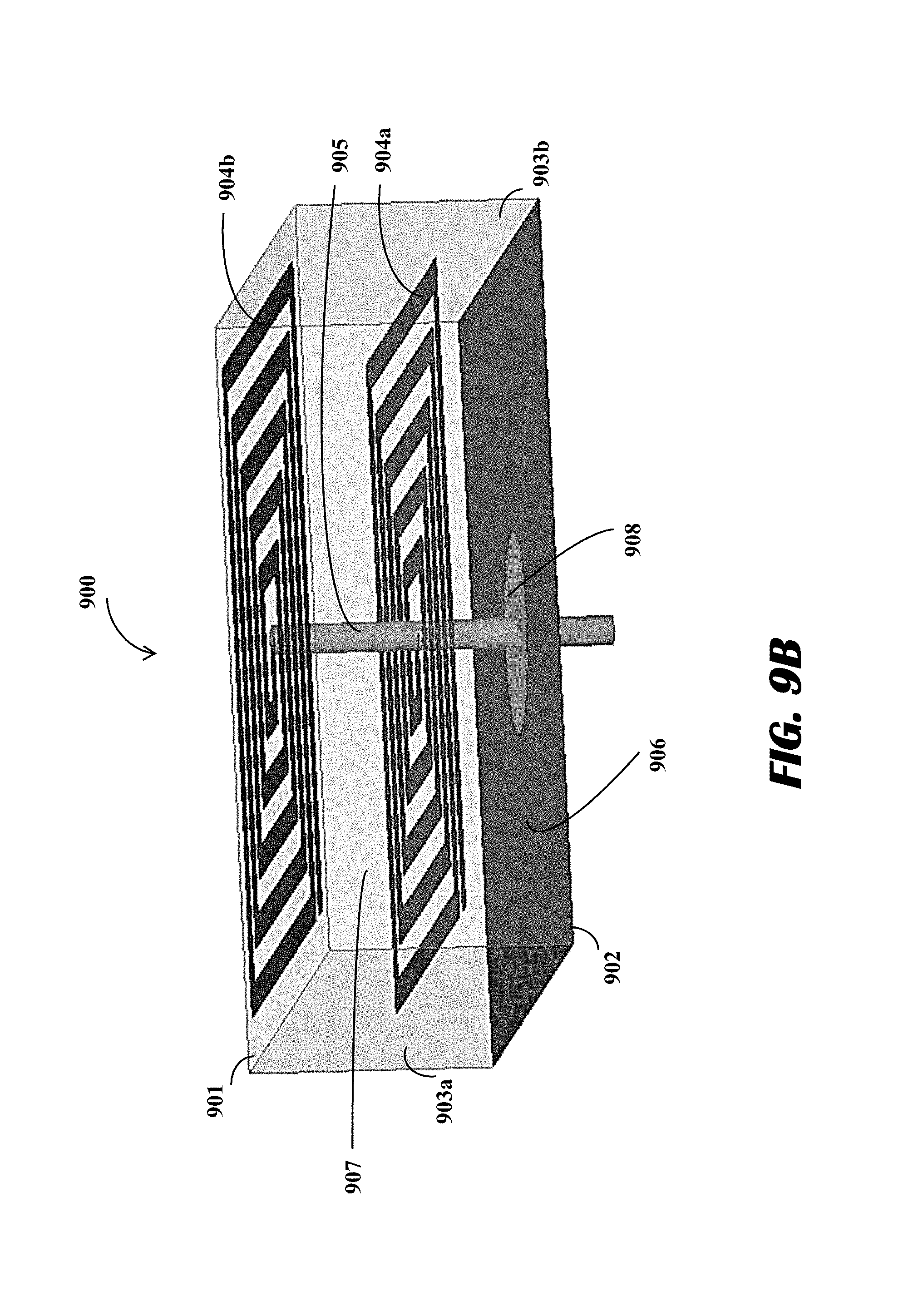
1. A near-field radio frequency (RF) power transfer system comprising a transmitter, the transmitter comprising: a first antenna element disposed on or below a first surface of a substrate and configured to carry a first current in a first direction during a first time period to generate a first RF radiation; a second antenna element disposed on or below the first surface of the substrate and configured to carry a second current in a second direction, distinct from and opposite to the first direction, during the first time period to generate a second RF radiation such that (i) a far-field portion of the second RF radiation substantially cancels a far-field portion of the first RF radiation, and (ii) a near-field portion of the second RF radiation does not substantially cancel a near-field portion of the first RF radiation; a ground plane disposed on or below a second surface of the substrate, wherein the second surface is opposite to the first surface; a first via passing through the ground plane, wherein the first via contains a first power feed line configured to supply the first current; and a second via passing through the ground plane, wherein the second via is distinct from the first via and contains a second power feed line configured to supply the second current.
2. The near-field RF power transfer system of claim 1, further comprising: a via passing through the ground plane, wherein the via contains a power feed line configured to supply the first and the second currents.
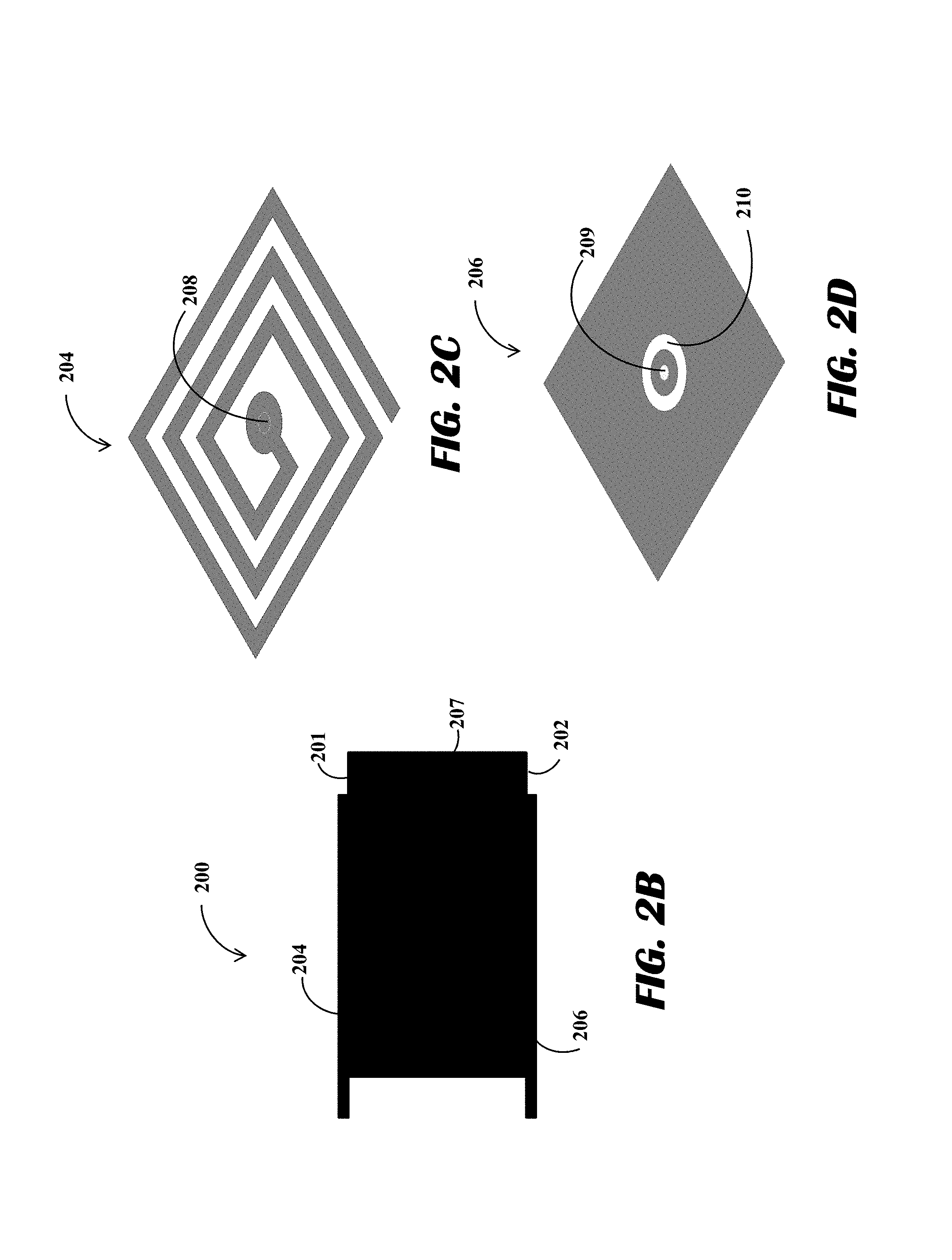
3. The near-field RF power transfer system of claim 1, wherein the first and second antenna elements are segments of a spiral antenna.
4. The near-field RF power transfer system of claim 1, wherein the first antenna element is a segment of a first pole of a dipole antenna, and the second antenna element is a segment of a second pole of the dipole antenna.
5. The near-field RF power transfer system of claim 1, wherein the first and second antenna elements are segments of a loop antenna.
6. The near-field RF power transfer system of claim 1, wherein the first and second antenna elements are segments of a loop antenna comprising concentric loops.
7. The near-field RF power transfer system of claim 1, wherein the first and second antenna elements are segments of a monopole antenna.
8. The near-field RF power transfer system of claim 1, wherein the first and second antenna elements are segments of a hybrid dipole antenna comprising two spiral poles.
9. The near-field RF power transfer system of claim 1, wherein the first and second antenna elements are segments of hierarchical spiral antenna.
10. The near-field RF power transfer system of claim 1, wherein the ground plane is constructed of a solid metal sheet of copper or a copper alloy.
11. The near-field RF power transfer system of claim 1, wherein the ground plane is constructed of metal strips arranged in shapes selected from the group consisting of a loop, a spiral, and a mesh.
12. The near-field RF power transfer system of claim 1, wherein the first and second antenna elements are constructed of copper or a copper alloy.
13. The near-field RF power transfer system of claim 1, wherein the far-field portion of the first RF radiation cancels out the far-field portion of a second RF radiation.
14. The near-field RF power transfer system of claim 1, wherein the ground plane is configured to reflect at least a portion of the RF radiation generated by the first and second antenna elements.
15. The near-field RF power transfer system of claim 1, wherein the ground plane is configured to cancel at least a portion of the RF radiation generated by the first and second antenna elements.
16. The near-field RF power transfer system of claim 1, wherein the power transfer system is configured as a power transmitter.
17. The near-field RF power transfer system of claim 1, wherein the substrate comprises a metamaterial of a predetermined magnetic permeability or electrical permittivity.
18. A method of near-field RF power transfer utilizing a transmitter that comprises first and second antenna elements, a ground plane, and first and second vias, the method comprising: supplying, through the first via passing through a ground plane, a first current to the first antenna element such that the first antenna element generates a first RF radiation; supplying, through the second via distinct from the first via and passing through the ground plane, a second current to the second antenna element such that the second antenna element generates a second RF radiation, wherein the first current is in a first direction and the second current is in a second direction, distinct from and opposite to the first direction such that (i) a far-field portion of the second RF radiation substantially cancels a far field portion of the first RF radiation, and (ii) a near-field portion of the second RF radiation does not substantially cancel a near-field portion of the first RF radiation, wherein the first and second antenna elements are disposed on or below a first surface of a substrate, and wherein the ground plane is disposed on or below a second surface of the substrate opposite to the first surface.
Description
TECHNICAL FIELD
This application relates generally to wireless power charging systems and more particularly to near-field radio frequency (RF) antennas for transmitting or receiving power.
BACKGROUND
Electronic devices, such as laptop computers, smartphones, portable gaming devices, tablets, or others, require power to operate. As generally understood, electronic devices are often charged at least once a day, or in high-use or power-hungry electronic devices, more than once a day. Such activity may be tedious and may present a burden to users. For example, a user may be required to carry chargers in case his electronic devices run out of power. In addition, some users have to find available power sources to connect to, which is inconvenient and time consuming. Lastly, some users must plug into a wall or some other power supply to be able to charge their electronic devices. Such activity may render electronic devices inoperable or not portable during charging.
Some conventional solutions include an inductive charging pad, which may employ magnetic induction or resonating coils. As understood in the art, such a solution still requires the electronic devices to: (i) be placed in a specific location on the inductive charging pad, and (ii) be particularly oriented for powering due to magnetic fields having a particular orientation. Furthermore, inductive charging units require large coils in both devices (i.e., the charger and the device being charged by the charger), which may not desirable due to size and cost, for example. Therefore, electronic devices may not sufficiently charge or may not receive a charge if not oriented properly on the inductive charging pad. And, users can be frustrated when an electronic device is not charged as expected after using a charging mat, thereby destroying the credibility of the charging mat.
Other solutions use far field RF wave transmission to create pockets of energy by constructive interference of RF waves at remote locations for charging a device. Such solutions, however, are better suited for particular uses and configurations as far field RF wave transmission solutions typically use numerous antenna arrays and circuitry for providing phase and amplitude control of the RF waves. Furthermore, far field antennas may not be efficient for near-field charging systems. Some antennas such as patch antennas have been used for near-field power transfer. However, the patch antennas also have low power transfer efficiency in near-field, particularly as the generated power may leak in all directions, rather than being concentrated in a particular area in near-field.
Therefore, there is a need in the art to address the above described drawbacks of far field antennas and near field antennas and construct near RF field antennas with high coupling efficiency.
SUMMARY
Systems disclosed herein address the aforementioned issues and may provide a number other benefits as well.
In one embodiment, a near-field radio frequency (RF) power transfer system, comprises: a first antenna element disposed on or below a first surface of a substrate and configured to carry a first current in a first direction during a first time period to generate a first RF radiation; a second antenna element disposed on or below the first surface of the substrate and configured to carry a second current in a second direction opposite to the first direction during the first time period to generate a second RF radiation such that the far-field portion of the second RF radiation cancels the far-field portion of the first RF radiation; and a ground plane disposed on or below a second surface of the substrate, wherein the second surface is opposite to the first surface.
In one embodiment, a method of near-field RF power transfer, the method comprises: supplying, through one or more vias through a ground plane, a first current to a first antenna element such that the first antenna generates a first RF radiation and a second current to a second antenna element such that the second antenna generates a second RF radiation, wherein the first current is in a first direction and the second current is in a second direction opposite to the first direction such that the far-field portion of the second RF radiation cancels the far field portion of the first RF radiation, wherein the first and second antenna elements are disposed on or below a first surface of a substrate, and wherein the ground plane is disposed on or below a second surface of the substrate opposite to the first surface and below the first and second antenna elements.
BRIEF DESCRIPTION OF THE DRAWINGS
The accompanying drawings constitute a part of this specification and illustrate embodiments of the subject matter disclosed herein.
FIGS. 1A and 1B are schematic illustrations of an exemplary system, according to an embodiment.
FIGS. 2A-2D are schematic illustrations of an exemplary system, according to an embodiment.
FIG. 3 is a schematic illustration of an exemplary system, according to an embodiment.
FIG. 4 is a schematic illustration of an exemplary system, according to an embodiment.
FIG. 5 is a schematic illustration of an exemplary system, according to an embodiment.
FIG. 6 is a schematic illustration of an exemplary system, according to an embodiment.
FIG. 7 is a schematic illustration of an exemplary system, according to an embodiment.
FIG. 8 is a schematic illustration of an exemplary system, according to an embodiment.
FIGS. 9A and 9B are schematic illustrations of an exemplary system, according to an embodiment.
DETAILED DESCRIPTION
Reference will now be made to the illustrative embodiments illustrated in the drawings, and specific language will be used here to describe the same. It will nevertheless be understood that no limitation of the scope of the claims or this disclosure is thereby intended. Alterations and further modifications of the inventive features illustrated herein, and additional applications of the principles of the subject matter illustrated herein, which would occur to one skilled in the relevant art and having possession of this disclosure, are to be considered within the scope of the subject matter disclosed herein. The present disclosure is here described in detail with reference to embodiments illustrated in the drawings, which form a part here. Other embodiments may be used and/or other changes may be made without departing from the spirit or scope of the present disclosure. The illustrative embodiments described in the detailed description are not meant to be limiting of the subject matter presented here.
Disclosed herein are various embodiments of power transmission systems with high power transfer efficiency in near-field, RF-based, power transfer coupling. Power transfer efficiency of a transmitter and a receiver in a power transfer system may be defined as percentage or ratio that relates the amount of power transmitted or produced by a transmitter and the amount of power collected by a receiver. Power transfer efficiency may depend upon the coupling of the transmitter and the receiver. If the transmitter and the receiver are well-coupled, most of the power transmitted by one or more transmit antennas of the transmitter is localized at one or more receive antennas of the receiver. On the other hand, if the transmitter and the receiver are not coupled well, relatively less power is localized at the receiver antennas, and the power is lost due to leakage in undesired directions. It is therefore desirable to have better-coupled power transmitters and receivers, wherein most of the electromagnetic power is trapped or otherwise localized between the transmitter and the receiver.
The embodiments of near-field power transfer systems described herein may include antenna elements that are constructed or printed close to each other in a meandered arrangement. In a meandered arrangement, neighboring antenna elements conduct currents that flow in opposite directions. This current flow entirely or almost entirely cancels out any far field RF radiation generated by the antennas or otherwise generated by the electromagnetic effects of the current flow. In other words, for a first current flowing in a first path, there may be a second current flowing in a second cancellation path that cancels the far field radiation produced by the first current flowing in the first path. Therefore, there may be no radiation of power to the far field. Such cancellation, however, may not occur in a near-field active zone, where the transfer of power may occur between the transmitter and the receiver. One having ordinary skill in the art will appreciate that one or more solutions to Maxwell's equations for time-varying electric fields and magnetic fields generated by the currents flowing in opposite directions, will dictate that far-field electromagnetic radiation will be canceled and that near-field electromagnetic radiation will not be canceled when currents flow in opposite directions. One ordinarily skilled in the art should also appreciate that a near-field active zone is defined by the presence of electromagnetic power in the immediate vicinity, proximate or adjacent to, the power transfer system. One ordinarily skilled in the art will further appreciate the near-field/far-field distinction. For example, near-field may refer to the immediate vicinity of the antenna elements, and may also include the radiating near field (Fresnel) region, and far-field may refer to areas beyond the immediate vicinity of the antenna elements.
The embodiments of the near-field power transfer systems described herein may include a ground plane behind the antennas. For a near-field power transfer system functioning as a transmitter, the ground plane may not allow power to be transferred behind the transmit antennas of the power transfer system by, for example, acting as a reflector for the electromagnetic waves generated by the transmitter antennas. Similarly, for a near-field power transfer system functioning as a receiver, the ground plane may not allow the received electromagnetic waves to radiate from the back of the receiver. Therefore, having one or more ground planes may localize or trap the electromagnetic power in between the transmitter and the receiver by blocking the leakage of power from the back of the transmitter and/or the receiver.
The antennas may be constructed to be in different shapes such as monopoles, meandered monopoles, dipoles, meandered dipoles, spirals, loops, and concentric loops. The antennas may also be constructed in hybrid configurations such as spiral dipoles. Furthermore, there may be hierarchical antennas, for example, an antenna with a first spiral dipole at a first hierarchical level and a second spiral dipole at a second hierarchical level above the first hierarchical level. In some embodiments, a single ground plane may be provided at the lowest hierarchical level. In other embodiments, each hierarchical level may include a ground plane. The hybrid structures or the hierarchical structures may be required for wideband and/or multiband designs. For example, a non-hierarchical or non-hybrid structure may be highly efficient at a first frequency and at a first distance between the transmitter and the receiver, but may be inefficient other frequencies and distances. Incorporating more complex structure such as hybrids and hierarchies allows for higher efficiencies along a range of frequencies and distances.
In some embodiments, the transmit antenna and the corresponding receive antenna may have to be mirror images of or symmetric to each other. In other words, a receive antenna may have the same or roughly the same shape and/or size configuration as a corresponding transmit antenna. Such mirroring may ensure better coupling and therefore result in higher power transfer efficiency. However, in other embodiments, the transmit antennas and the receive antennas may not have to be symmetric to each other. Furthermore, for non-mirror pairings, the antennas disclosed herein may be paired with other antennas (e.g. patches, dipoles, slots); in these cases the near-field coupling efficiency may be still acceptable for certain applications. Different types of transmit antennas may be mixed and matched with different types of receive antennas.
As the frequency decreases and the wavelength increases, in conventional systems, the matching antennas may have to be made longer and longer. Embodiments of the near-field power transfer systems described herein may also provide miniaturized antennas. For example, in many conventional systems, a half wave-dipole antenna used to transmit and/or receive 900 MHz electromagnetic waves is typically 33.3 centimeters (cm) or roughly 1 foot (ft) from one end of the antenna to the other end of the antenna. But embodiments described herein may achieve such results using smaller form-factors. A meandered arrangement disclosed herein may allow the antennas to be folded or spiraled onto each other. A long antenna can therefore may be printed or constructed in a relatively smaller housing. For example, transmitters/receivers operating at very low frequencies, for example 400 MHz, may be miniaturized to antenna sizes from about 6 millimeter (mm) by 6 mm to about 14 mm by 14 mm. Furthermore, the near-field power transfer systems disclosed herein have significantly higher power transfer efficiencies compared to the transmitters and receivers known in the art.
The near-field power transfer systems disclosed herein may be used in electronic devices, such as mobile phones, wearables, and toys. For example, a first power transfer system may be a part of or associated with a transmitter embedded within a charging mat, and a second power transfer system may be a part of or associated with a receiver embedded within a mobile phone. When the mobile phone is placed in proximity to the charging mat, the transmitter may transfer power to the receiver. In some embodiments, the near-field power transfer systems may be used in conjunction with far field power transfer systems. For instance, a mobile phone may have both a near-field receiver and a far field receiver. When the mobile phone is placed on a charging mat having a near-field transmitter, the near-field receiver in the mobile phone may receive power from the near-field transmitter. When the mobile phone is taken off from the charging mat and placed on a different location, the far field receiver in the mobile phone may receive power from a far field transmitter.
FIG. 1A shows a top perspective view of a schematic drawing of an exemplary near-field power transfer system 100. FIG. 1B shows a bottom perspective view of a schematic drawing of an exemplary near-field power transfer system 100. The power transfer system 100 may comprise a top surface 101, a bottom surface 102, and sidewalls 103. In some embodiments, a housing containing components of the power transfer system 100 may be constructed of a material creating minimal obstructions for electromagnetic waves to pass through. In other embodiments, different portions of the housing may be constructed with materials having different electromagnetic properties such as permeability and permittivity. For example, the top surface 101 may allow electromagnetic waves to pass through with minimal obstruction while the sidewalls 103 may obstruct electromagnetic waves by attenuation, absorption, reflection, or other techniques known in the art.
The power transfer system 100 may radiate RF energy and thus transfer power when the power transfer system 100 is adjacent to a second power transfer system (not shown). As such, a power transfer system 100 may be on a "transmit side," so as to function as a power transmitter, or the power transfer system 100 may be on a "receive side," so as to function as a power receiver. In some embodiments, where the power transfer system 100 is associated with a transmitter, the power transfer system 100 (or subcomponents of the power transfer system 100) may be integrated into the transmitter device, or may be externally wired to the transmitter. Likewise, in some embodiments, where the power transfer system 100 is associated with a receiver, the power transfer system 100 (or subcomponents of the power transfer system 100) may be integrated into the receiver device, or may be externally wired to the receiver.
A substrate 107 may be disposed within a space defined between the top surface 101, sidewalls 103, and the bottom surface 102. In some embodiments, the power transfer system 100 may not include a housing and the substrate 107 may include the top surface 101, sidewalls 103, and the bottom surface 102. The substrate 107 may comprise any material capable of insulating, reflecting, absorbing, or otherwise housing electrical lines conducting current, such as metamaterials. The metamaterials may be a broad class of synthetic materials that are engineered to yield desirable magnetic permeability and electrical permittivity. At least one of the magnetic permeability and electrical permittivity may be based upon power-transfer requirements, and/or compliance constraints for government regulations. The metamaterials disclosed herein may receive radiation or may generate radiation, and may act as thin reflectors.
An antenna 104 may be constructed on or below the top surface 101. When the power transfer system 100 is associated with a power transmitter, the antenna 104 may be used for transmitting electromagnetic waves. Alternatively, when the power transfer system 100 is associated with a power receiver, the antenna 104 may be used for receiving electromagnetic waves. In some embodiments, the power transfer system 100 may operate as a transceiver and the antenna 104 may both transmit and receive electromagnetic waves. The antenna 104 may be constructed from materials such as metals, alloys, metamaterials and composites. For example, the antenna 104 may be made of copper or copper alloys. The antenna 104 may be constructed to have different shapes based on the power transfer requirements. In the exemplary system 100 shown in FIG. 1A and FIG. 1B, the antenna 104 is constructed in a shape of a spiral including antenna segments 110 that are disposed close to each other. The currents flowing through the antenna segments 110 may be in opposite directions. For example, if the current in the antenna segment 110b is flowing from left to right of FIG. 1A, the current each of the antenna segments 110a, 110c may be flowing from right to left. The opposite flow of the current results in mutual cancellation of the electromagnetic radiation the far field of the power transfer system 100. In other words, the far field electromagnetic radiation generated by one or more antenna segments 110 left of an imaginary line 115 is cancelled out by the far field electromagnetic radiation generated by one or more antenna segments 110 right of the line 115. Therefore, there may be no leakage of power in the far field of the power transfer system 100. Such cancellation, however, may not occur in a near-field active zone of the power transfer system 100, where the transfer of power may occur.
The power transfer system 100 may include a ground plane 106 at or above the bottom surface 102. The ground plane 106 may be formed by materials such as metal, alloys, and composites. In an embodiment, the ground plane 106 may be formed by copper or a copper alloy. In some embodiments, the ground plane 106 may be constructed of a solid sheet of material. In other embodiments, the ground plane 106 may be constructed using material strips arranged in shapes such as loops, spirals, and meshes. A via 105 carrying a power feed line (not shown) to the antenna may pass through the ground plane 106. The power feed line may supply current to the antenna 104. In some embodiments, the ground plane 106 may be electrically connected to the antenna 104. In some embodiments, the ground plane 106 may not be electrically connected to the antenna 104. For such implementations, an insulation area 108 to insulate the via 105 from the ground plane 106 may be constructed between the via 105 and the ground plane 106. In some embodiments, the ground plane 106 may act as a reflector of the electromagnetic waves generated by the antenna 104. In other words, the ground plane may not allow electromagnetic transmission beyond the bottom surface of the power transfer system 100 by cancelling and/or reflecting the transmission image formed beyond the bottom surface. Reflecting the electromagnetic waves by the ground plane may reinforce the electromagnetic waves transmitted by the antenna 104 from or towards the top surface 101. Therefore, there may be no leakage of electromagnetic power from the bottom surface 102.
Therefore, as a result of the antenna 104 and the ground plane 106, the electromagnetic waves transmitted or received by the power transfer system 100 accumulate in the near field of the system 100. The leakage to the far field of the system 100 is minimized.
FIG. 2A schematically illustrates a top perspective view of an exemplary near-field power transfer system 200, according to an embodiment of the disclosure. In some embodiments, the power transfer system 200 may be a part of or associated with a power transmitter. In other embodiments, the power transfer system 200 may be a part of or associated with a power receiver. The power transfer system 200 may comprise a housing defined by a top surface 201, a bottom surface (not shown), and sidewalls 203. In some embodiments, the housing may be constructed of a material creating minimal obstructions for electromagnetic waves to pass through. In other embodiments, different portions of the housing may be constructed with materials having different electromagnetic properties such as permeability and permittivity. For example, the top surface 201 may allow electromagnetic waves to pass through with minimal obstruction while the sidewalls 203 may obstruct electromagnetic waves by attenuation, absorption, reflection, or other techniques known in the art.
A substrate 207 may be disposed within a space defined between the top surface 201, sidewalls 203, and the bottom surface 202. In some embodiments, the power transfer system 200 may not include a housing and the substrate 207 may include the top surface 201, sidewalls 203, and the bottom surface 202. The substrate 207 may comprise any material capable of insulating, reflecting, absorbing, or otherwise housing electrical lines conducting current, such as metamaterials. The metamaterials may be a broad class of synthetic materials that are engineered to yield desirable magnetic permeability and electrical permittivity. At least one of the magnetic permeability and electrical permittivity may be based upon power-transfer requirements, and/or compliance constraints for government regulations. The metamaterials disclosed herein may receive radiation or may generate radiation, and may act as thin reflectors.
An antenna 204 may be constructed on or below the top surface 201. When the power transfer system 200 is a part of or associated with a power transmitter, the antenna 204 may be used for transmitting electromagnetic waves. Alternatively, when the power transfer system 200 is a part of or associated with a power receiver, the antenna 204 may be used for receiving electromagnetic waves. In some embodiments, the power transfer system 200 may operate as a transceiver and the antenna 204 may both transmit and receive electromagnetic waves. The antenna 204 may be constructed from materials such as metals, alloys, metamaterials, and composites. For example, the antenna 204 may be made of copper or copper alloys. The antenna 204 may be constructed to have different shapes based on the power transfer requirements. In the exemplary system 200 shown in FIG. 2A the antenna 204 is constructed in a shape of a spiral including antenna segments which are disposed close to each other. A signal feed line (not shown) may be connected to the antenna 204 through a via 205.
FIG. 2B schematically illustrates a side view of the exemplary power transmission system 200. As shown, an upper metal layer may form the antenna 204, and a lower metal layer may form the ground plane 206. The substrate 207 may be disposed in between the upper and lower metal layer. The substrate 207 may include materials such as FR4, metamaterials, or any other materials known in the art. The metamaterials may be a broad class of synthetic materials that are engineered to yield desirable magnetic permeability and electrical permittivity. At least one of the magnetic permeability and electrical permittivity may have to be based upon power-transfer requirements, and/or compliance constraints for government regulations. The metamaterials disclosed herein may receive radiation or generate radiation, and may act as thin reflectors.
FIG. 2C schematically illustrates a top perspective view of antenna 204. The antenna 204 comprises a connection point 209 for a feed line (not shown) coming through the via 205. FIG. 2D schematically illustrates a side perspective view of the ground plane 206. In an embodiment, the ground plane 206 comprises a solid metal layer. In other embodiments, the ground plane 206 may include structures such as stripes, meshes, and lattices and may not be completely solid. The ground plane 206 may also comprise a socket 209 for the via 205 to pass through. Around the socket 209, the ground plane 206 may also include an insulating region 210 to insulate the socket 209 from the rest of the ground plane 206. In some embodiments, the ground plane may have an electrical connection to a line coming through the via, and the insulating region 210 may not be required.
FIG. 3 schematically illustrates a top perspective view of an exemplary near-field power transfer system 300, according to an embodiment of the disclosure. In some embodiments, the power transfer system 300 may be a part of or associated with a power transmitter. In other embodiments, the power transfer system 300 may be a part of or associated with a power receiver. The power transfer system 300 may comprise a housing defined by a top surface 301, a bottom surface (not shown), and sidewalls 303. In some embodiments, the housing may be constructed of a material creating minimal obstructions for electromagnetic waves to pass through. In other embodiments, different portions of the housing may be constructed with materials having different electromagnetic properties such as permeability and permittivity. For example, the top surface 301 may allow electromagnetic waves to pass through with minimal obstruction while the sidewalls 303 may obstruct electromagnetic waves by attenuation, absorption, reflection, or other techniques known in the art.
A substrate 307 may be disposed within a space defined between the top surface 301, sidewalls 303, and the bottom surface 302. In some embodiments, the power transfer system 300 may not include a housing and the substrate 307 may include the top surface 301, sidewalls 303, and the bottom surface 302. The substrate 307 may comprise any material capable of insulating, reflecting, absorbing, or otherwise housing electrical lines conducting current, such as metamaterials. The metamaterials may be a broad class of synthetic materials that are engineered to yield desirable magnetic permeability and electrical permittivity. At least one of the magnetic permeability and electrical permittivity may be based upon power-transfer requirements, and/or compliance constraints for government regulations. The metamaterials disclosed herein may receive radiation or may transmit radiation, and may act as thin reflectors.
An antenna 304 may be constructed on or below the top surface 3. When the power transfer system 300 is a part of or associated with a power transmitter, the antenna 304 may be used for transmitting electromagnetic waves. Alternatively, when the power transfer system 300 is a part of or associated with a power receiver, the antenna 304 may be used for receiving electromagnetic waves. In some embodiments, the power transfer system 300 may operate as a transceiver and the antenna 304 may both transmit and receive electromagnetic waves. The antenna 304 may be constructed from materials such as metals, alloys, metamaterials and composites. For example, the antenna 304 may be made of copper or copper alloys. The antenna 304 may be constructed to have different shapes based on the power transfer requirements. In the exemplary system 300 shown in FIG. 3, the antenna 304 is constructed in a shape of a dipole including a first meandered pole 309a and a second meandered pole 309b. A first power feed line (not shown) to the first meandered pole 309a may be carried by a first via 305a and a second power feed line (not shown) to the second meandered pole 309b may be carried by a second via 305b. The first power feed line may supply current to the first meandered pole 309a and the second power feed line may supply current to the second meandered pole 309b. The first meandered pole 309a includes antenna segments 310 which are disposed close to each other and the second meandered pole 309b includes antenna segments 311 also disposed close to each other. The currents flowing through the neighboring antenna segments 310, 311 may be in opposite directions. For example, if the current in a antenna segment 310b is flowing from left to right of FIG. 3, the current in each of the antenna segments 310a, 310c may be flowing from right to left. The opposite flow of the current across any number of antenna segments 310 of the power transfer system 300 results in mutual cancellation of the far field electromagnetic radiation generated by the power transfer system 300. Additionally or alternatively, the far field electromagnetic radiation generated by the antenna segments 310 of the first pole 309a may be cancelled by the electromagnetic radiation generated by antenna segments 311 of the second pole 309b. It should be appreciated that the far field cancellation may occur across any number of segments 310, 311 and/or across any number of poles 309. Therefore, there may be no leakage of power in the far field of the power transfer system 300. Such cancellation, however, may not occur in a near-field active zone of the power transfer system 300, where the transfer of power may occur.
The power transfer system 300 may include a ground plane (not shown) at or above the bottom surface. The ground plane may be formed by materials such as metal, alloys, and composites. In an embodiment, the ground plane may be formed by copper or a copper alloy. In some embodiments, the ground plane may be constructed of a solid sheet of material. In other embodiments, the ground plane may be constructed using material strips arranged in shapes such as loops, spirals, and meshes. The vias 305 carrying the power feed lines to the antenna may pass through the ground plane. In some embodiments, the ground plane may be electrically connected to the antenna. In some embodiments, the ground plane may not be electrically connected to the antenna 304. For such implementations, an insulation area to insulate the vias 305 from the ground plane may be constructed between the vias 305 and the ground plane. In some embodiments, the ground plane may act as a reflector of the electromagnetic waves generated by the antenna 304. In other words, the ground plane may not allow electromagnetic transmission beyond the bottom surface of the power transfer system 300 by cancelling and/or reflecting the transmission image formed beyond the bottom surface. Reflecting the electromagnetic waves by the ground plane may reinforce the electromagnetic waves transmitted by the antenna 304 from or towards the top surface 301. Therefore, there may be no leakage of electromagnetic power from the bottom surface.
FIG. 4 schematically illustrates a top perspective view of an exemplary near-field power transfer system 400, according to an embodiment of the disclosure. In some embodiments, the power transfer system 400 may be a part of or associated with a power transmitter. In other embodiments, the power transfer system 400 may be a part of or associated with a power receiver. The power transfer system 400 may comprise a housing defined by a top surface 401, a bottom surface (not shown), and sidewalls 103. In some embodiments, the housing may be constructed of a material creating minimal obstructions for electromagnetic waves to pass through. In other embodiments, different portions of the housing may be constructed with materials having different electromagnetic properties such as permeability and permittivity. For example, the top surface 401 may allow electromagnetic waves to pass through with minimal obstruction while the sidewalls 403 may obstruct electromagnetic waves by attenuation, absorption, reflection, or other techniques known in the art.
A substrate 407 may be disposed within a space defined between the top surface 401, sidewalls 403, and the bottom surface 402. In some embodiments, the power transfer system 400 may not include a housing and the substrate 407 may include the top surface 401, sidewalls 403, and the bottom surface 402. The substrate 407 may comprise any material capable of insulating, reflecting, absorbing, or otherwise housing electrical lines conducting current, such as metamaterials. The metamaterials may be a broad class of synthetic materials that are engineered to yield desirable magnetic permeability and electrical permittivity. At least one of the magnetic permeability and electrical permittivity may be based upon power-transfer requirements, and/or compliance constraints for government regulations. The metamaterials disclosed herein may receive radiation or may generate radiation, and may act as thin reflectors.
An antenna 404 may be constructed on or below the top surface 401. When the power transfer system 400 is a part of or associated with a power transmitter, the antenna 404 may be used for transmitting electromagnetic waves. Alternatively, when the power transfer system 400 is a part of or associated with a power receiver, the antenna 404 may be used for receiving electromagnetic waves. In some embodiments, the power transfer system 400 may operate as a transceiver and the antenna 404 may both transmit and receive electromagnetic waves. The antenna 404 may be constructed from materials such as metals, alloys, and composites. For example, the antenna 404 may be made of copper or copper alloys. The antenna 404 may be constructed to have different shapes based on the power transfer requirements. In the exemplary system 400 shown in FIG. 4, the antenna 404 is constructed in a shape of a loop including loop segments 410 which are disposed close to each other. The currents flowing through the neighboring loop segments 410 may be in opposite directions. For example, if the current in a first loop segment 410a is flowing from left to right of FIG. 4, the current in a second loop segment 410b may be flowing from right to left. The opposite flow of the current results in mutual cancellation of the electromagnetic radiation the far field of the power transfer system 400. Therefore, there may be no leakage of power in the far field of the power transfer system 400. Such cancellation, however, may not occur in a near-field active zone of the power transfer system 400, where the transfer of power may occur.
The power transfer system 400 may include a ground plane (not shown) at or above the bottom surface. The ground plane may be formed by materials such as metal, alloys, metamaterials, and composites. In an embodiment, the ground plane may be formed by copper or a copper alloy. In some embodiments, the ground plane may be constructed of a solid sheet of material. In other embodiments, the ground plane may be constructed using material strips arranged in shapes such as loops, spirals, and meshes. The vias 405 carrying the power feed lines (not shown) to the antenna may pass through the ground plane. The power feed lines may provide current to the antenna 404. In some embodiments, the ground plane 106 may be electrically connected to the antenna. In some embodiments, the ground plane may not be electrically connected to the antenna 404. For such implementations, an insulation area to insulate the vias 405 from the ground plane may be constructed between the vias 305 and the ground plane. In some embodiments, the ground plane may act as a reflector of the electromagnetic waves generated by the antenna 404. In other words, the ground plane may not allow electromagnetic transmission beyond the bottom surface of the power transfer system 300 by cancelling and/or reflecting the transmission image formed beyond the bottom surface. Reflecting the electromagnetic waves by the ground plane may reinforce the electromagnetic waves transmitted by the antenna 404 from or towards the top surface 401. Therefore, there may be no leakage of electromagnetic power from the bottom surface.
FIG. 5 schematically illustrates a top perspective view of an exemplary near-field power transfer system 500, according to an embodiment of the disclosure. In some embodiments, the power transfer system 500 may be a part of or associated with a power transmitter. In other embodiments, the power transfer system 500 may be a part of or associated with a power receiver. In other embodiments, the power transfer system 500 may be a part of or associated with a transceiver. The power transfer system 500 may comprise a housing defined by a top surface 501, a bottom surface (not shown), and sidewalls 503. In some embodiments, the housing may be constructed of a material creating minimal obstructions for electromagnetic waves to pass through. In other embodiments, different portions of the housing may be constructed with materials having different electromagnetic properties such as permeability and permittivity. For example, the top surface 501 may allow electromagnetic waves to pass through with minimal obstruction while the sidewalls 503 may obstruct electromagnetic waves by attenuation, absorption, reflection, or other techniques known in the art.
A substrate 507 may be disposed within a space defined between the top surface 501, sidewalls 503, and the bottom surface 502. In some embodiments, the power transfer system 500 may not include a housing and the substrate 507 may include the top surface 501, sidewalls 503, and the bottom surface 502. The substrate 507 may comprise any material capable of insulating, reflecting, absorbing, or otherwise housing electrical lines conducting current, such as metamaterials. The metamaterials may be a broad class of synthetic materials that are engineered to yield desirable magnetic permeability and electrical permittivity. At least one of the magnetic permeability and electrical permittivity may be based upon power-transfer requirements, and/or compliance constraints for government regulations. The metamaterials disclosed herein may receive radiation or may transmit radiation, and may act as thin reflectors.
An antenna 504 may be constructed on or below the top surface 501. When the power transfer system 500 is a part of or associated with a power transmitter, the antenna 504 may be used for transmitting electromagnetic waves. Alternatively, when the power transfer system 500 is a part of or associated with a power receiver, the antenna 504 may be used for receiving electromagnetic waves. In some embodiments, the power transfer system 500 may operate as a transceiver and the antenna 504 may both transmit and receive electromagnetic waves. The power feed lines (not shown) to the antenna 504 may be carried by the vias 505. The power feed lines may provide current to the antenna 504. The antenna 504 may be constructed from materials such as metals, alloys, metamaterials, and composites. For example, the antenna 504 may be made of copper or copper alloys. The antenna 504 may be constructed to have different shapes based on the power transfer requirements. In the exemplary system 500 shown in FIG. 5, the antenna 504 is constructed in a shape of concentric loops including antenna segments 510 which are disposed close to each other. As shown in FIG. 5, a single concentric loop may include two of the antenna segments 510. For example, the innermost loop may include a first antenna segment 510c to the right of an imaginary line 512 roughly dividing the loops into two halves, and a corresponding second antenna segment 510c' to the left of the imaginary line 512. The currents flowing through the neighboring antenna segments 510 may be in opposite directions. For example, if the current in the antenna segments 510a', 510b', 510c' is flowing from left to right of FIG. 5, the current in each of the antenna segments 510a, 510b, 510c may be flowing from right to left. The opposite flow of the current results in mutual cancellation of the electromagnetic radiation at the far field of the power transfer system 500. Therefore, there may be no transfer of power to the far field of the power transfer system 500. Such cancellation, however, may not occur in a near-field active zone of the power transfer system 500, where the transfer of power may occur. One ordinarily skilled in the art will appreciate the cancellation of electromagnetic radiation in the far field and absence of such cancellation in the near-field is dictated by one or more solutions of Maxwell's equations for time-varying electric and magnetic fields generated by the currents flowing in opposite directions. One ordinarily skilled in the art should further appreciate the near field active zone is defined by the presence of electromagnetic power in the immediate vicinity of the power transfer system 500.
The power transfer system 500 may include a ground plane (not shown) at or above the bottom surface. The ground plane may be formed by materials such as metal, alloys, and composites. In an embodiment, the ground plane may be formed by copper or a copper alloy. In some embodiments, the ground plane may be constructed of a solid sheet of material. In other embodiments, the ground plane may be constructed using material strips arranged in shapes such as loops, spirals, and meshes. The vias 505 carrying the power feed lines to the antenna may pass through the ground plane. In some embodiments, the ground plane may be electrically connected to the antenna. In some embodiments, the ground plane may not be electrically connected to the antenna 504. For such implementations, an insulation area to insulate the vias 505 from the ground plane may be constructed between the vias 305 and the ground plane. In some embodiments, the ground plane may act as a reflector of the electromagnetic waves generated by the antenna 504. In other words, the ground plane may not allow electromagnetic transmission beyond the bottom surface of the power transfer system 500 by cancelling and/or reflecting the transmission image formed beyond the bottom surface. Reflecting the electromagnetic waves by the ground plane may reinforce the electromagnetic waves transmitted by the antenna 504 from or towards the top surface 501. Therefore, there may be no leakage of electromagnetic power from the bottom surface.
FIG. 6 schematically illustrates a top perspective view of an exemplary near-field power transfer system 600, according to an embodiment of the disclosure. In some embodiments, the power transfer system 600 may be a part of or associated with a power transmitter. In other embodiments, the power transfer system 600 may be a part of or associated with a power receiver. The power transfer system 600 may comprise a housing defined by a top surface 601, a bottom surface (not shown), and sidewalls 603. In some embodiments, the housing may be constructed of a material creating minimal obstructions for electromagnetic waves to pass through. In other embodiments, different portions of the housing may be constructed with materials having different electromagnetic properties such as permeability and permittivity. For example, the top surface 601 may allow electromagnetic waves to pass through with minimal obstruction while the sidewalls 603 may obstruct electromagnetic waves by attenuation, absorption, reflection, or other techniques known in the art.
A substrate 607 may be disposed within a space defined between the top surface 601, sidewalls 603, and the bottom surface 602. In some embodiments, the power transfer system 600 may not include a housing and the substrate 607 may include the top surface 601, sidewalls 603, and the bottom surface 602. The substrate 607 may comprise any material capable of insulating, reflecting, absorbing, or otherwise housing electrical lines conducting current, such as metamaterials. The metamaterials may be a broad class of synthetic materials that are engineered to yield desirable magnetic permeability and electrical permittivity. At least one of the magnetic permeability and electrical permittivity may be based upon power-transfer requirements, and/or compliance constraints for government regulations. The metamaterials disclosed herein may receive radiation or may transmit radiation, and may act as thin reflectors.
An antenna 604 may be constructed on or below the top surface 601. When the power transfer system 600 is a part of or associated with a power transmitter, the antenna 604 may be used for transmitting electromagnetic waves. Alternatively, when the power transfer system 600 is a part of or associated with a power receiver, the antenna 604 may be used for receiving electromagnetic waves. In some embodiments, the power transfer system 600 may operate as a transceiver and the antenna 604 may both transmit and receive electromagnetic waves. The antenna 604 may be constructed from materials such as metals, alloys, and composites. For example, the antenna 604 may be made of copper or copper alloys. The antenna 604 may be constructed to have different shapes based on the power transfer requirements. In the exemplary system 600 shown in FIG. 6, the antenna 604 is constructed in a shape of a monopole. A via 605 may carry a power feed line (not shown) to the antenna 604. The power feed line may provide current to the antenna 604.
The power transfer system 600 may include a ground plane (not shown) at or above the bottom surface. The ground plane may be formed by materials such as metal, alloys, and composites. In an embodiment, the ground plane may be formed by copper or a copper alloy. In some embodiments, the ground plane may be constructed of a solid sheet of material. In other embodiments, the ground plane may be constructed using material strips arranged in shapes such as loops, spirals, and meshes. The via 605 carrying the power feed line to the antenna 604 may pass through the ground plane. In some embodiments, the ground plane may be electrically connected to the antenna. In some embodiments, the ground plane may not be electrically connected to the antenna 604. For such implementations, an insulation area to insulate the via 605 from the ground plane may be constructed between the via 605 and the ground plane. In some embodiments, the ground plane may act as a reflector of the electromagnetic waves generated by the antenna 604. In other words, the ground plane may not allow electromagnetic transmission beyond the bottom surface of the power transfer system 600 by cancelling and/or reflecting the transmission image formed beyond the bottom surface. Reflecting the electromagnetic waves by the ground plane may reinforce the electromagnetic waves transmitted by the antenna 604 from or towards the top surface 601. Therefore, there may be no leakage of electromagnetic power from the bottom surface.
FIG. 7 schematically illustrates a top perspective view of an exemplary near-field power transfer system 700, according to an embodiment of the disclosure. In some embodiments, the power transfer system 700 may be a part of or associated with a power transmitter. In other embodiments, the power transfer system 700 may be a part of or associated with a power receiver. The power transfer system 700 may comprise a housing defined by a top surface 701, a bottom surface (not shown), and sidewalls 103. In some embodiments, the housing may be constructed of a material creating minimal obstructions for electromagnetic waves to pass through. In other embodiments, different portions of the housing may be constructed with materials having different electromagnetic properties such as permeability and permittivity. For example, the top surface 701 may allow electromagnetic waves to pass through with minimal obstruction while the sidewalls 703 may obstruct electromagnetic waves by attenuation, absorption, reflection, or other techniques known in the art.
A substrate 707 may be disposed within a space defined between the top surface 701, sidewalls 703, and the bottom surface 702. In some embodiments, the power transfer system 700 may not include a housing and the substrate 707 may include the top surface 701, sidewalls 703, and the bottom surface 702. The substrate 707 may comprise any material capable of insulating, reflecting, absorbing, or otherwise housing electrical lines conducting current, such as metamaterials. The metamaterials may be a broad class of synthetic materials that are engineered to yield desirable magnetic permeability and electrical permittivity. At least one of the magnetic permeability and electrical permittivity may be based upon power-transfer requirements, and/or compliance constraints for government regulations. The metamaterials disclosed herein may receive radiation or may transmit radiation, and may act as thin reflectors.
An antenna 704 may be constructed on or below the top surface 701. When the power transfer system 700 is a part of or associated with a power transmitter, the antenna 704 may be used for transmitting electromagnetic waves. Alternatively, when the power transfer system 700 is a part of or associated with a power receiver, the antenna 704 may be used for receiving electromagnetic waves. In some embodiments, the power transfer system 700 may operate as a transceiver and the antenna 704 may both transmit and receive electromagnetic waves. The antenna 704 may be constructed from materials such as metals, alloys, and composites. For example, the antenna 704 may be made of copper or copper alloys. A via 705 may carry a power feed line (not shown) to the antenna. The power feed line may provide current to the antenna 704. The antenna 704 may be constructed to have different shapes based on the power transfer requirements. In the exemplary system 700 shown in FIG. 7, the antenna 704 is constructed in a shape of a monopole including antenna segments 710 placed close to each other. The currents flowing through the neighboring antenna segments 710 may be in opposite directions. For example, if the current in the antenna segment 710b is flowing from left to right of FIG. 7, the current each of the antenna segments 710a, 710c may be flowing from right to left. The opposite flow of the current results in mutual cancellation of the electromagnetic radiation in the far field of the power transfer system 700. Therefore, there may be no transfer of power in the far field of the power transfer system 700. Such cancellation, however, may not occur in a near-field active zone of the power transfer system 700, where the transfer of power may occur. One ordinarily skilled in the art will appreciate the cancellation of electromagnetic radiation in the far field and absence of such cancellation in the near-field is dictated by one or more solutions of Maxwell's equations for time-varying electric and magnetic fields generated by the currents flowing in opposite directions. One ordinarily skilled in the art should further appreciate the near field active zone is defined by the presence of electromagnetic power in the immediate vicinity of the power transfer system 700. The power transfer system 700 may include a ground plane (not shown) at or above the bottom surface. The ground plane may be formed by materials such as metal, alloys, and composites. In an embodiment, the ground plane may be formed by copper or a copper alloy. In some embodiments, the ground plane may be constructed of a solid sheet of material. In other embodiments, the ground plane may be constructed using material strips arranged in shapes such as loops, spirals, and meshes. The via 705 carrying the power feed line to the antenna 704 may pass through the ground plane. In some embodiments, the ground plane may be electrically connected to the antenna. In some embodiments, the ground plane may not be electrically connected to the antenna 704. For such implementations, an insulation area to insulate the via 705 from the ground plane may be constructed between the via 705 and the ground plane. In some embodiments, the ground plane may act as a reflector of the electromagnetic waves generated by the antenna 704. In other words, the ground plane may not allow electromagnetic transmission beyond the bottom surface of the power transfer system 700 by cancelling and/or reflecting the transmission image formed beyond the bottom surface. Reflecting the electromagnetic waves by the ground plane may reinforce the electromagnetic waves transmitted by the antenna 704 from or towards the top surface 701. Therefore, there may be no leakage of electromagnetic power from the bottom surface.
FIG. 8 schematically illustrates a top perspective view of an exemplary near-field power transfer system 800, according to an embodiment of the disclosure. In some embodiments, the power transfer system 800 may be a part of or associated with a power transmitter. In other embodiments, the power transfer system 800 may be a part of or associated with a power receiver. The power transfer system 800 may comprise a housing defined by a top surface 801, a bottom surface (not shown), and sidewalls 803. In some embodiments, the housing may be constructed of a material creating minimal obstructions for electromagnetic waves to pass through. In other embodiments, different portions of the housing may be constructed with materials having different electromagnetic properties such as permeability and permittivity. For example, the top surface 801 may allow electromagnetic waves to pass through with minimal obstruction while the sidewalls 803 may obstruct electromagnetic waves by attenuation, absorption, reflection, or other techniques known in the art.
A substrate 807 may be disposed within a space defined between the top surface 801, sidewalls 803, and the bottom surface 802. In some embodiments, the power transfer system 800 may not include a housing and the substrate 807 may include the top surface 801, sidewalls 803, and the bottom surface 802. The substrate 807 may comprise any material capable of insulating, reflecting, absorbing, or otherwise housing electrical lines conducting current, such as metamaterials. The metamaterials may be a broad class of synthetic materials that are engineered to yield desirable magnetic permeability and electrical permittivity. At least one of the magnetic permeability and electrical permittivity may be based upon power-transfer requirements, and/or compliance constraints for government regulations. The metamaterials disclosed herein may receive radiation or may transmit radiation, and may act as thin reflectors.
An antenna 804 may be constructed on or below the top surface 801. When the power transfer system 800 is a part of or associated with a power transmitter, the antenna 804 may be used for transmitting electromagnetic waves. Alternatively, when the power transfer system 800 is a part of or associated with a power receiver, the antenna 804 may be used for receiving electromagnetic waves. In some embodiments, the power transfer system 800 may operate as a transceiver and the antenna 804 may both transmit and receive electromagnetic waves. The antenna 804 may be constructed from materials such as metals, alloys, and composites. For example, the antenna 804 may be made of copper or copper alloys. The antenna 804 may be constructed to have different shapes based on the power transfer requirements. In the exemplary system 800 shown in FIG. 8, the antenna 804 is constructed as a hybrid dipoles comprising a first spiral pole 820a and a second spiral pole 820b. A first power feed line supplying current to the first spiral pole 820a may be provided through a first via 805a and a second power feed supplying current the second spiral pole 820b may be provided through a second via 805b. The antenna segments in each of the spiral poles 820 may mutually cancel the electromagnetic radiation in the far field generated by the spiral dipoles 820 thereby reducing the transfer of power to the far field. For example, the antenna segments in the first spiral pole 820a may cancel the far field electromagnetic radiation generated by each other. Additionally, or in the alternative, the far field radiation generated by one or more antenna segments of the first spiral pole 820a may be cancelled by the far field radiation generated by one or more antenna segments of the second spiral pole 820b. One ordinarily skilled in the art will appreciate the cancellation of electromagnetic radiation in the far field and absence of such cancellation in the near-field is dictated by one or more solutions of Maxwell's equations for time-varying electric and magnetic fields generated by the currents flowing in opposite directions.
The power transfer system 800 may include a ground plane (not shown) at or above the bottom surface. The ground plane may be formed by materials such as metal, alloys, and composites. In an embodiment, the ground plane may be formed by copper or a copper alloy. In some embodiments, the ground plane may be constructed of a solid sheet of material. In other embodiments, the ground plane may be constructed using material strips arranged in shapes such as loops, spirals, and meshes. The vias 805 carrying the power feed lines to the antenna may pass through the ground plane. In some embodiments, the ground plane may be electrically connected to the antenna. In some embodiments, the ground plane may not be electrically connected to the antenna 804. For such implementations, an insulation area to insulate the vias 805 from the ground plane may be constructed between the vias 805 and the ground plane. In some embodiments, the ground plane may act as a reflector of the electromagnetic waves generated by the antenna 804. In other words, the ground plane may not allow electromagnetic transmission beyond the bottom surface of the power transfer system 800 by cancelling and/or reflecting the transmission image formed beyond the bottom surface. Reflecting the electromagnetic waves by the ground plane may reinforce the electromagnetic waves transmitted by the antenna 804 from or towards the top surface 801. Therefore, there may be no leakage of electromagnetic power from the bottom surface.
The hybrid antenna 804 may be required for wideband and/or multiband designs. For example, a non-hybrid structure may be highly efficient at a first frequency and at a first distance between the transmitter and the receiver, but may be at inefficient other frequencies and distances. Incorporating more complex structure such as a hybrid antenna 80 may allow for higher efficiencies along a range of frequencies and distances.
FIG. 9A and FIG. 9B schematically illustrate a top perspective view and a side perspective view respectively of an exemplary near-field power transfer system 900, according to an embodiment of the disclosure. In some embodiments, the power transfer system 900 may be a part of or associated with a power transmitter. In other embodiments, the power transfer system 100 may be a part of or associated with a power receiver. The power transfer system 900 may comprise a housing defined by a top surface 901, a bottom surface 902, and sidewalls 903. In some embodiments, the housing may be constructed of a material creating minimal obstructions for electromagnetic waves to pass through. In other embodiments, different portions of the housing may be constructed with materials having different electromagnetic properties such as permeability and permittivity. For example, the top surface 901 may allow electromagnetic waves to pass through with minimal obstruction while the sidewalls 903 may obstruct electromagnetic waves by attenuation, absorption, reflection, or other techniques known in the art.
A substrate 907 may be disposed within a space defined between the top surface 901, sidewalls 903, and the bottom surface 902. In some embodiments, the power transfer system 900 may not include a housing and the substrate 907 may include the top surface 901, sidewalls 903, and the bottom surface 902. The substrate 907 may comprise any material capable of insulating, reflecting, absorbing, or otherwise housing electrical lines conducting current, such as metamaterials. The metamaterials may be a broad class of synthetic materials that are engineered to yield desirable magnetic permeability and electrical permittivity. At least one of the magnetic permeability and electrical permittivity may be based upon power-transfer requirements, and/or compliance constraints for government regulations. The metamaterials disclosed herein may receive radiation or may transmit radiation, and may act as thin reflectors.
The power transfer system may include hierarchical antennas 904 that may be constructed on or below the top surface 901. When the power transfer system 900 is a part of or associated with a power transmitter, the antennas 904 may be used for transmitting electromagnetic waves. Alternatively, when the power transfer system 900 is a part of or associated with a power receiver, the antennas 904 may be used for receiving electromagnetic waves. In some embodiments, the power transfer system 900 may operate as a transceiver and the antennas 904 may both transmit and receive electromagnetic waves. The antennas 904 may be constructed from materials such as metals, alloys, and composites. For example, the antennas 904 may be made of copper or copper alloys. The antennas 904 may be constructed to have different shapes based on the power transfer requirements. In the exemplary system 900 shown in FIG. 9A and FIG. 9B, the antennas 104 are constructed in a hierarchical spiral structure with a level_zero hierarchical antenna 904a and a level_one hierarchical antenna 904b. Each of the hierarchical antennas 904 may include antenna segments, wherein antenna segments have currents flowing in the opposite directions to cancel out the far field radiations. For example, the antenna segments in the level_zero hierarchical antenna 904a may cancel the far field electromagnetic radiation generated by each other. Additionally, or in the alternative, the far field radiation generated by one or more antenna segments of the level_zero hierarchical antenna 904a may be cancelled by the far field radiation generated by one or more antenna segments of the level_one hierarchical antenna 904b. A power feed line (not shown) to the antennas is carried through a via 905. The power feed line may supply current to the antenna 904.
The power transfer system 900 may include a ground plane 906 at or above the bottom surface 902. The ground plane 906 may be formed by materials such as metal, alloys, and composites. In an embodiment, the ground plane 906 may be formed by copper or a copper alloy. In some embodiments, the ground plane 906 may be constructed of a solid sheet of material. In other embodiments, the ground plane 906 may be constructed using material strips arranged in shapes such as loops, spirals, and meshes. The via 905 carrying a power feed line to the antenna may pass through the ground plane 906. In some embodiments, the ground plane 906 may be electrically connected to one or more of the antennas 904. In some embodiments, the ground plane 906 may not be electrically connected to the antennas 904. For such implementations, an insulation area 908 to insulate the via 905 from the ground plane 906 may be constructed between the via 905 and the ground plane 906. In some embodiments, the ground plane 906 may act as a reflector of the electromagnetic waves generated by the antennas 904. In other words, the ground plane may not allow electromagnetic transmission beyond the bottom surface of the power transfer system 900 by cancelling and/or reflecting the transmission image formed beyond the bottom surface. Reflecting the electromagnetic waves by the ground plane may reinforce the electromagnetic waves transmitted by the antennas 904 from or towards the top surface 901. Therefore, there may be no leakage of electromagnetic power from the bottom surface 902. In some embodiments, there may be multiple ground planes, with a ground plane for each of the hierarchical antennas 904. In some embodiments, the hierarchical antennas have different power feed lines carried through multiple vias.
The hierarchical antennas 904 may be required for wideband and/or multiband designs. For example, a non-hierarchical structure may be highly efficient at a first frequency and at a first distance between the transmitter and the receiver, but may be inefficient at other frequencies and distances. Incorporating more complex structures, such as hierarchical antennas 904, may allow for higher efficiencies along a range of frequencies and distances.
The foregoing method descriptions and the process flow diagrams are provided merely as illustrative examples and are not intended to require or imply that the steps of the various embodiments must be performed in the order presented. The steps in the foregoing embodiments may be performed in any order. Words such as "then," "next," etc. are not intended to limit the order of the steps; these words are simply used to guide the reader through the description of the methods. Although process flow diagrams may describe the operations as a sequential process, many of the operations can be performed in parallel or concurrently. In addition, the order of the operations may be re-arranged. A process may correspond to a method, a function, a procedure, a subroutine, a subprogram, and the like. When a process corresponds to a function, the process termination may correspond to a return of the function to a calling function or a main function.
The preceding description of the disclosed embodiments is provided to enable any person skilled in the art to make or use the embodiments described herein and variations thereof. Various modifications to these embodiments will be readily apparent to those skilled in the art, and the generic principles defined herein may be applied to other embodiments without departing from the spirit or scope of the subject matter disclosed herein. Thus, the present disclosure is not intended to be limited to the embodiments shown herein but is to be accorded the widest scope consistent with the following claims and the principles and novel features disclosed herein.
While various aspects and embodiments have been disclosed, other aspects and embodiments are contemplated. The various aspects and embodiments disclosed are for purposes of illustration and are not intended to be limiting, with the true scope and spirit being indicated by the following claims.
* * * * *
D00000
D00001
D00002
D00003
D00004
D00005
D00006
D00007
D00008
D00009
D00010
D00011
XML
uspto.report is an independent third-party trademark research tool that is not affiliated, endorsed, or sponsored by the United States Patent and Trademark Office (USPTO) or any other governmental organization. The information provided by uspto.report is based on publicly available data at the time of writing and is intended for informational purposes only.
While we strive to provide accurate and up-to-date information, we do not guarantee the accuracy, completeness, reliability, or suitability of the information displayed on this site. The use of this site is at your own risk. Any reliance you place on such information is therefore strictly at your own risk.
All official trademark data, including owner information, should be verified by visiting the official USPTO website at www.uspto.gov. This site is not intended to replace professional legal advice and should not be used as a substitute for consulting with a legal professional who is knowledgeable about trademark law.