Infusion cooking assembly
Choy
U.S. patent number 10,314,431 [Application Number 15/335,602] was granted by the patent office on 2019-06-11 for infusion cooking assembly. The grantee listed for this patent is Shawn Choy. Invention is credited to Shawn Choy.


| United States Patent | 10,314,431 |
| Choy | June 11, 2019 |
Infusion cooking assembly
Abstract
An infusion cooking assembly for infusing flavor into items during cooking includes a housing that has a top, which is open. A set of holes is positioned through a bottom of the housing. A set of cups is positionable in an internal space of the housing. Each of set of rods is coupled to and extends bidirectionally from a lower surface of a respective cup. The rods are complementary to the holes. A lid is reversibly couplable to the housing to cover the top. A tube is coupled to the lid and is fluidically coupled to interior spaces of the cups. The tube is configured for placement of an item to be cooked and flavored, such as a chicken. The cups are configured to insert flavoring items into the interior spaces. The flavoring items are heated and infused into the item to be cooked as the item is cooked.
| Inventors: | Choy; Shawn (Oakland, CA) | ||||||||||
|---|---|---|---|---|---|---|---|---|---|---|---|
| Applicant: |
|
||||||||||
| Family ID: | 62020051 | ||||||||||
| Appl. No.: | 15/335,602 | ||||||||||
| Filed: | October 27, 2016 |
Prior Publication Data
| Document Identifier | Publication Date | |
|---|---|---|
| US 20180116451 A1 | May 3, 2018 | |
| Current U.S. Class: | 1/1 |
| Current CPC Class: | A47J 36/06 (20130101); A47J 36/20 (20130101); A47J 36/38 (20130101); A47J 27/002 (20130101) |
| Current International Class: | A47J 36/38 (20060101); A47J 36/06 (20060101); A47J 36/20 (20060101); A47J 27/00 (20060101) |
| Field of Search: | ;99/345,426,532,352,332,483,421HH,421HV,421R,421H |
References Cited [Referenced By]
U.S. Patent Documents
| 849290 | April 1907 | Vanderbilt |
| 1339625 | May 1920 | Holloway |
| 3392665 | July 1968 | Harnest |
| D217789 | June 1970 | Oddo |
| 4027583 | June 1977 | Spanek |
| 4407189 | October 1983 | Bentson |
| 4421017 | December 1983 | Ross |
| 4450759 | May 1984 | Steibel |
| 4557188 | December 1985 | Spanek |
| 4558197 | December 1985 | Wyatt |
| 4633773 | January 1987 | Jay |
| 4709626 | December 1987 | Hamlyn |
| 4924768 | May 1990 | Jay |
| D316007 | April 1991 | Wagner |
| 5025715 | June 1991 | Sir |
| 5069117 | December 1991 | Schlessel |
| 5081916 | January 1992 | Kuhling |
| 5106642 | April 1992 | Ciofalo |
| 5301602 | April 1994 | Ryczek |
| 5442999 | August 1995 | Meister |
| 5575198 | November 1996 | Lowery |
| 5638742 | June 1997 | Kassaseya |
| 5662028 | September 1997 | Fraga |
| 5730046 | March 1998 | Battaglia |
| 5791235 | August 1998 | Anselmo |
| 5842409 | December 1998 | Loffler |
| 5893320 | April 1999 | Demaree |
| 5913965 | June 1999 | Gargano |
| D412297 | July 1999 | Roach |
| 5981926 | November 1999 | Kim |
| 6039373 | March 2000 | Horn |
| 6062131 | May 2000 | Holland |
| 6119585 | September 2000 | Guidry |
| 6192792 | February 2001 | Gremillion |
| 6216586 | April 2001 | Burgin |
| 6265004 | July 2001 | Cagle |
| 6272976 | August 2001 | Berryman |
| 6314869 | November 2001 | Bourgeois, Jr. |
| D453488 | February 2002 | McCauley |
| 6349632 | February 2002 | Beck, Jr. |
| D461682 | August 2002 | Fandrey |
| 6427582 | August 2002 | Measom |
| 6460452 | October 2002 | Hester |
| 6467399 | October 2002 | Boutte |
| 6487964 | December 2002 | Snoke |
| 6502501 | January 2003 | Simon |
| 6502503 | January 2003 | Bell, Jr. |
| 6503551 | January 2003 | Hester |
| 6553896 | April 2003 | Heide |
| D488741 | April 2004 | Moya |
| D505827 | June 2005 | Riddle, III |
| D506352 | June 2005 | Dow |
| 6945161 | September 2005 | Battaglia |
| D513930 | January 2006 | Novi |
| 7040219 | May 2006 | D'Amato |
| D522807 | June 2006 | Dow |
| 7144596 | December 2006 | Snoke et al. |
| D547603 | July 2007 | Passman |
| D557071 | December 2007 | Zemel |
| D558519 | January 2008 | Zemel |
| D560967 | February 2008 | Zemel |
| D564286 | March 2008 | Zemel |
| D573838 | July 2008 | Jones |
| D591105 | April 2009 | Hodges |
| 7549369 | June 2009 | Zimmerman |
| 7565863 | July 2009 | Tschetter |
| 7879381 | February 2011 | Dow |
| 7946221 | May 2011 | Hull, Jr. |
| D639186 | June 2011 | Shapiro |
| D639601 | June 2011 | Borovicka |
| D639656 | June 2011 | Shapiro |
| 8110237 | February 2012 | Smith |
| D657612 | April 2012 | Cloutier |
| D671355 | November 2012 | Zmrhal |
| 8397630 | March 2013 | Oswald |
| D689245 | September 2013 | Rowe |
| 8539877 | September 2013 | Levy |
| D694477 | November 2013 | Rowe |
| D700004 | February 2014 | Weskamp |
| 8813636 | August 2014 | Oswald |
| D727678 | April 2015 | Minor |
| D737103 | August 2015 | Cloutier |
| 9155423 | October 2015 | Malone |
| D818760 | May 2018 | Abbo |
| 10015975 | July 2018 | Parrish |
| 2002/0100371 | August 2002 | Snoke |
| 2002/0195001 | December 2002 | Hester |
| 2003/0056656 | March 2003 | Marco, Jr. |
| 2004/0187699 | September 2004 | Citrynell |
| 2005/0172823 | August 2005 | Riddle, III |
| 2005/0257693 | November 2005 | Tschetter |
| 2006/0057267 | March 2006 | Dow |
| 2006/0219101 | October 2006 | McIlwee |
| 2006/0266227 | November 2006 | Britt |
| 2006/0283335 | December 2006 | Vasquez |
| 2007/0181006 | August 2007 | Measom |
| 2009/0087535 | April 2009 | Smith |
| 2010/0018413 | January 2010 | Thomas |
| 2011/0209627 | September 2011 | Wong |
| 2011/0226135 | September 2011 | Oswald |
| 2012/0174799 | July 2012 | Borovicka |
| 2013/0112087 | May 2013 | Hassell |
| 2013/0216691 | August 2013 | Sudmalis |
Claims
I claim:
1. An infusion cooking assembly comprising: a housing defining an internal space, said housing having a top, said top being open; a set of holes positioned through a bottom of said housing; a set of cups, each said cup defining an interior space, each said cup having an upper surface, said upper surface being open, said set of cups being substantially complementary to said internal space; a set of rods, said rods being complementary to said holes, each said rod being coupled to and extending bidirectionally from a lower surface of a respective said cup; a lid complementary to said top, said lid being reversibly couplable to said housing to cover said top; a tube coupled to said lid, said tube being fluidically coupled to said interior spaces of said cups; and wherein said housing is positioned for insertion of said set of cups, wherein said cups are configured for insertion of flavoring items into said interior spaces, wherein said lid is positioned for coupling to said housing such that said tube is configured for placement of an item to be cooked and flavored, such as a chicken, wherein said housing is configured for placement proximate to a heat source, such that the flavoring items are heated and infused into the item to be cooked as the item is cooked.
2. The assembly of claim 1, further including said housing comprising an annular wall extending from said top to said bottom.
3. The assembly of claim 1, further including said housing being substantially circularly shaped when viewed from said top.
4. The assembly of claim 1, further including said set of cups comprising from one to six said cups.
5. The assembly of claim 4, further including said set of cups comprising from two to five said cups.
6. The assembly of claim 5, further including said set of cups comprising four said cups.
7. The assembly of claim 1, further comprising: said cups being sized such that a spacing is present between adjacent said cups when said set of cups is positioned in said internal space; and said cups being sized such that a gap is present between said set of cups and an interior surface of said annular wall when said set of cups is positioned in said internal space.
8. The assembly of claim 1, further comprising: a first section of each said rod being positioned in said interior space of said respective said cup; a second section of each said rod extending through and protruding from said bottom of said housing when said set of cups is positioned in said internal space; and wherein said rods are positioned on said cups such that said rods are configured to transfer heat from the heat source to the flavoring items positioned in said cups.
9. The assembly of claim 1, further including said rods being substantially circular when viewed longitudinally.
10. The assembly of claim 1, further including said rods comprising metal.
11. The assembly of claim 10, further including said rods comprising stainless steel.
12. The assembly of claim 1, further including said tube being circularly shaped when viewed longitudinally.
13. The assembly of claim 1, further including said housing, said cups, said lid, and said tube comprising heat-resistant material.
14. The assembly of claim 13, further including said housing, said cups, said lid, and said tube comprising ceramic.
15. An infusion cooking assembly comprising: a housing defining an internal space, said housing having a top, said top being open, said housing comprising an annular wall extending from said top to a bottom, said housing being substantially circularly shaped when viewed from said top, said housing comprising heat-resistant material, said housing comprising ceramic; a set of holes positioned through said bottom of said housing; a set of cups, each said cup defining an interior space, each said cup having an upper surface, said upper surface being open, said set of cups being substantially complementary to said internal space, said set of cups comprising from one to six said cups, said set of cups comprising from two to five said cups, said set of cups comprising four said cups, said cups being sized such that a spacing is present between adjacent said cups when said set of cups is positioned in said internal space, said cups being sized such that a gap is present between said set of cups and an interior surface of said annular wall when said set of cups is positioned in said internal space, said cups comprising heat-resistant material, said cups comprising ceramic; a set of rods, said rods being complementary to said holes, each said rod being coupled to and extending bidirectionally from a lower surface of a respective said cup, a first section of each said rod being positioned in said interior space of said respective said cup, a second section of each said rod extending through and protruding from said bottom of said housing when said set of cups is positioned in said internal space, wherein said rods are positioned on said cups such that said rods are configured to transfer heat from a heat source to the flavoring items positioned in said cups, said rods being substantially circular when viewed longitudinally, said rods comprising metal, said rods comprising stainless steel; a lid complementary to said top, said lid being reversibly couplable to said housing to cover said top, said lid comprising heat-resistant material, said lid comprising ceramic; a tube coupled to said lid, said tube being fluidically coupled to said interior spaces of said cups, said tube being circularly shaped when viewed longitudinally, said tube comprising heat-resistant material, said tube comprising ceramic; and wherein said housing is positioned for insertion of said set of cups, wherein said cups are configured for insertion of flavoring items into said interior spaces, wherein said lid is positioned for coupling to said housing such that said tube is configured for placement of an item to be cooked and flavored, such as a chicken, wherein said housing is configured for placement proximate to the heat source, wherein said rods are positioned on said cups such that said rods are configured to transfer heat from the heat source to the flavoring items positioned in said cups such that the flavoring items are heated and infused into the item to be cooked as the item is cooked.
Description
CROSS-REFERENCE TO RELATED APPLICATIONS
Not Applicable
STATEMENT REGARDING FEDERALLY SPONSORED RESEARCH OR DEVELOPMENT
Not Applicable
THE NAMES OF THE PARTIES TO A JOINT RESEARCH AGREEMENT
Not Applicable
INCORPORATION-BY-REFERENCE OF MATERIAL SUBMITTED ON A COMPACT DISC OR AS A TEXT FILE VIE THE OFFICE ELECTRONIC FILING SYSTEM
Not Applicable
STATEMENT REGARDING PRIOR DISCLOSURES BY THE INVENTOR OR JOINT INVENTOR
Not Applicable
BACKGROUND OF THE INVENTION
(1) Field of the Invention
The disclosure relates to cooking assemblies.
(2) Description of Related Art Including Information Disclosed Under 37 CFR 1.97 and 1.98
The prior art relates to cooking assemblies and more particularly pertains to a new cooking assembly for infusing flavor into items during cooking.
BRIEF SUMMARY OF THE INVENTION
An embodiment of the disclosure meets the needs presented above by generally comprising a housing that has a top, which is open. A set of holes is positioned through a bottom of the housing. A set of cups is positionable in an internal space of the housing. Each of set of rods is coupled to and extends bidirectionally from a lower surface of a respective cup. The rods are complementary to the holes. A lid is reversibly couplable to the housing to cover the top. A tube is coupled to the lid and is fluidically coupled to interior spaces of the cups. The tube is configured for placement of an item to be cooked and flavored, such as a chicken. The cups are configured to insert flavoring items into the interior spaces. The flavoring items are heated and infused into the item to be cooked as the item is cooked.
There has thus been outlined, rather broadly, the more important features of the disclosure in order that the detailed description thereof that follows may be better understood, and in order that the present contribution to the art may be better appreciated. There are additional features of the disclosure that will be described hereinafter and which will form the subject matter of the claims appended hereto.
The objects of the disclosure, along with the various features of novelty which characterize the disclosure, are pointed out with particularity in the claims annexed to and forming a part of this disclosure.
BRIEF DESCRIPTION OF SEVERAL VIEWS OF THE DRAWING(S)
The disclosure will be better understood and objects other than those set forth above will become apparent when consideration is given to the following detailed description thereof. Such description makes reference to the annexed drawings wherein:
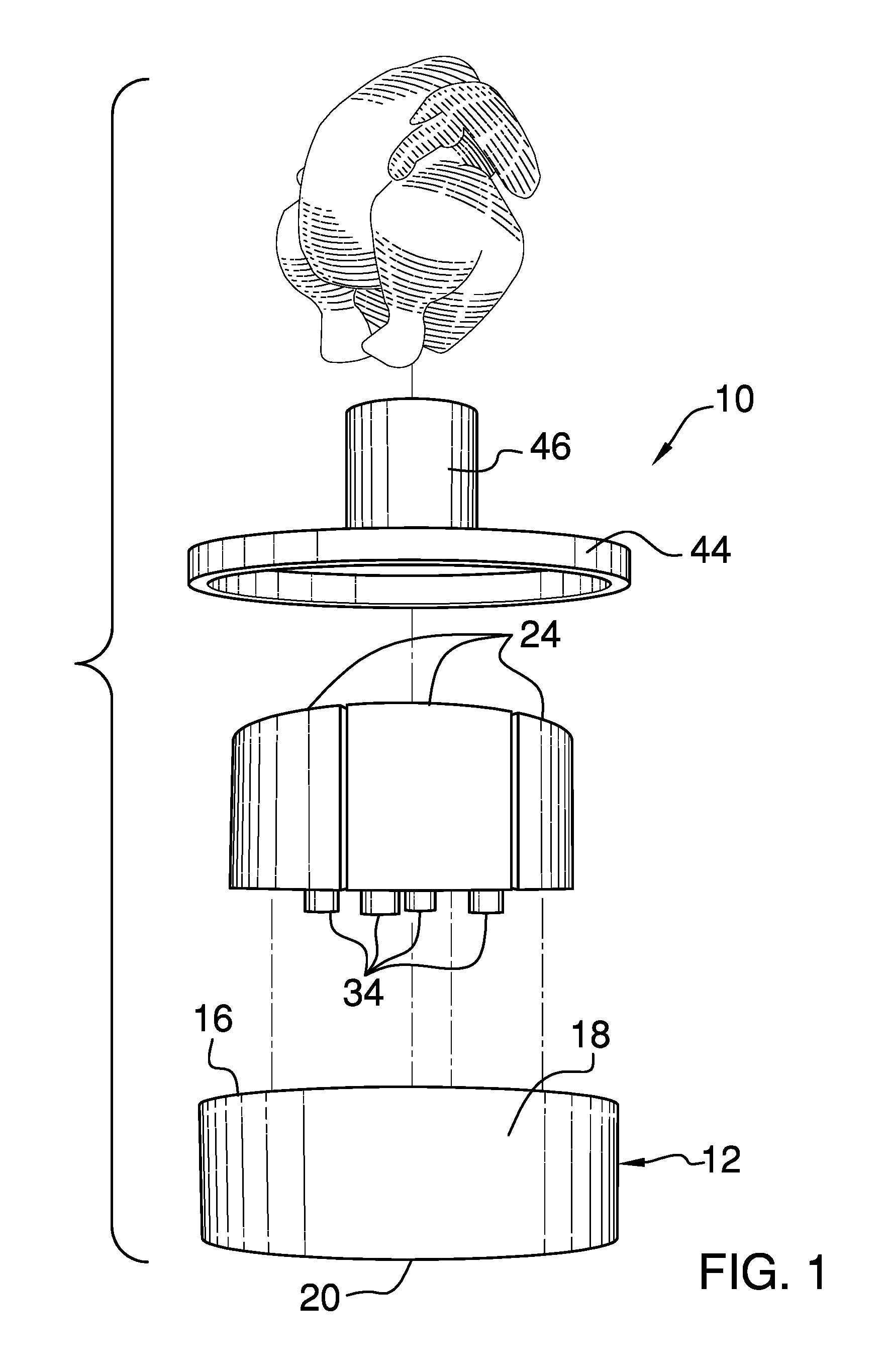
FIG. 1 is an exploded view of an infusion cooking assembly according to an embodiment of the disclosure.
FIG. 2 is a top view of an embodiment of the disclosure.
FIG. 3 is a bottom view of an embodiment of the disclosure.
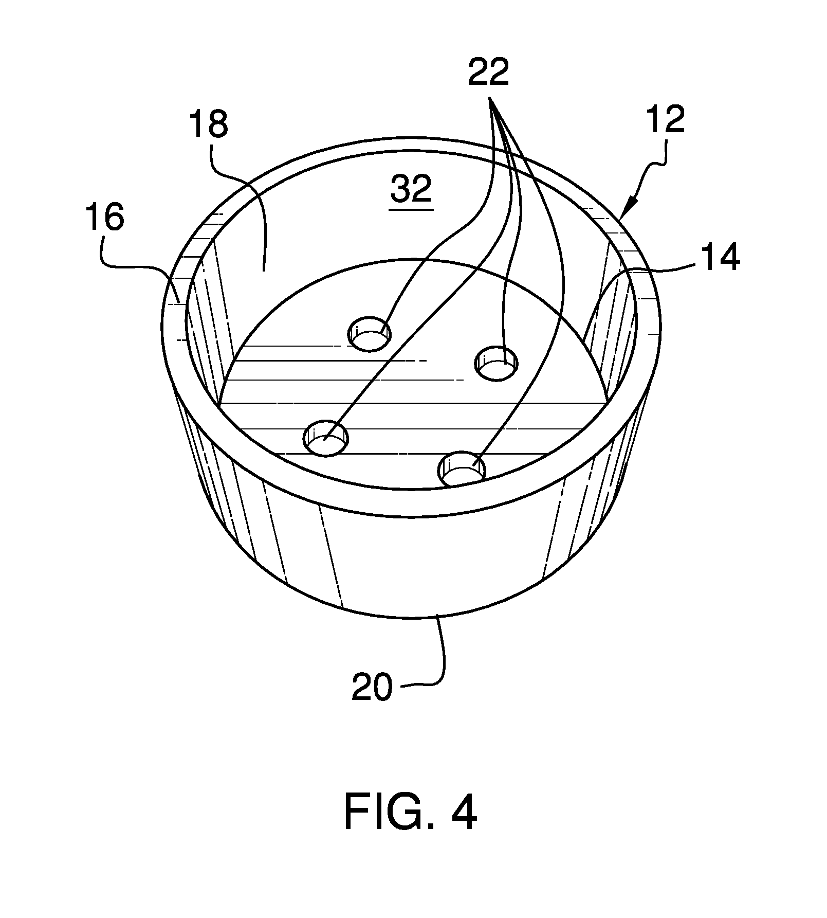
FIG. 4 is a top view of an embodiment of the disclosure.
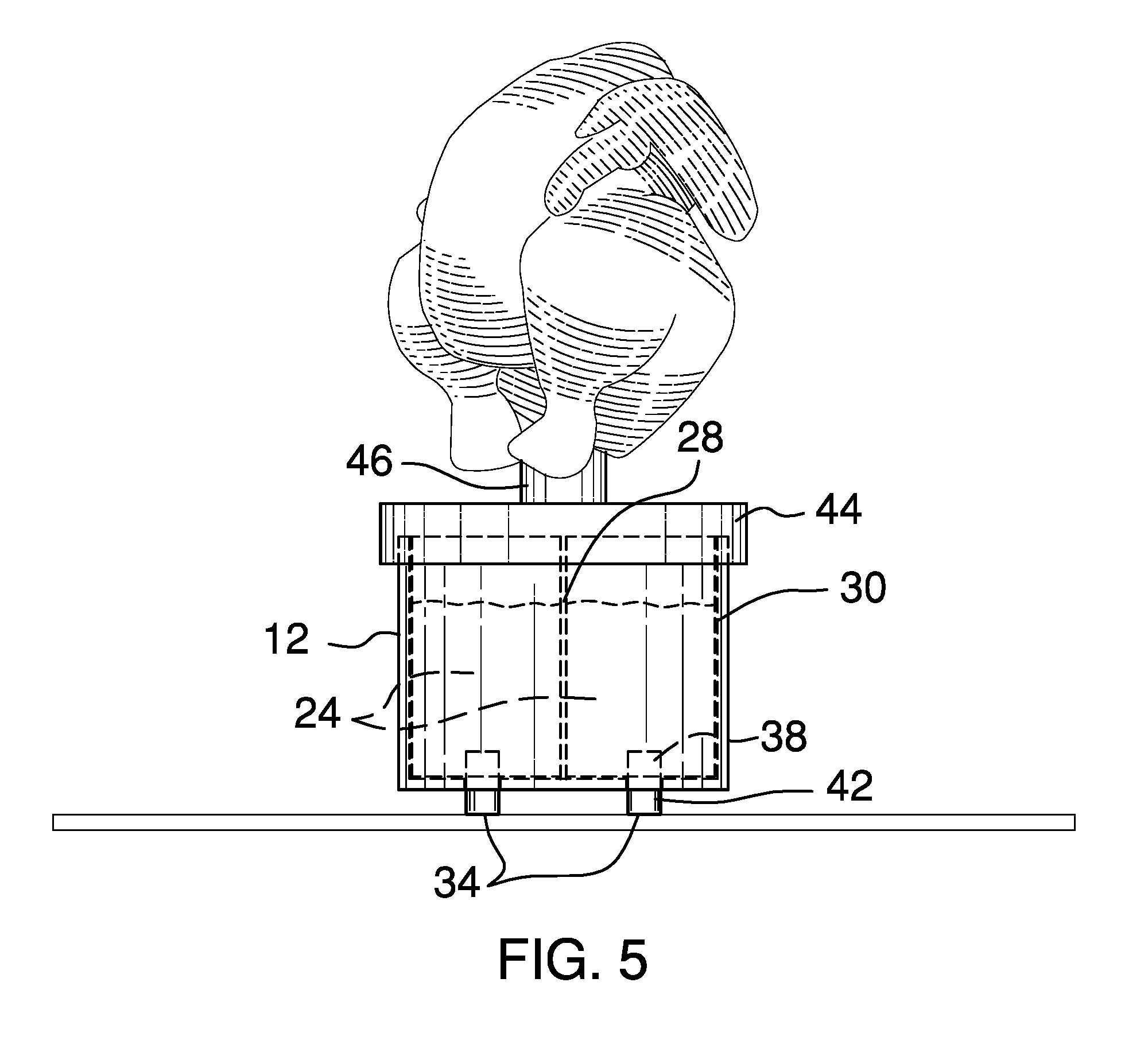
FIG. 5 is an in-use view of an embodiment of the disclosure.
DETAILED DESCRIPTION OF THE INVENTION
With reference now to the drawings, and in particular to FIGS. 1 through 5 thereof, a new cooking assembly embodying the principles and concepts of an embodiment of the disclosure and generally designated by the reference numeral 10 will be described.
As best illustrated in FIGS. 1 through 5, the infusion cooking assembly 10 generally comprises a housing 12 that defines an internal space 14. The housing 12 has a top 16 that is open. The housing 12 comprises an annular wall 18 that extends from the top 16 to a bottom 20. In one embodiment, the housing 12 is substantially circularly shaped when viewed from the top 16. The housing 12 comprises heat-resistant material. In another embodiment, the housing 12 comprises ceramic. A set of holes 22 is positioned through the bottom 20 of the housing 12.
Each of a set of cups 24 defines an interior space 40. Each cup 24 has an upper surface 26 that is open. The set of cups 24 is substantially complementary to the internal space 14. In one embodiment, the set of cups 24 comprises from one to six cups 24. In another embodiment, the set of cups 24 comprises from two to five cups 24. In yet another embodiment, the set of cups 24 comprises four cups 24.
The cups 24 are sized such that a spacing 28 is present between adjacent cups 24 when the set of cups 24 is positioned in the internal space 14. The cups 24 also are sized such that a gap 30 is present between the set of cups 24 and an interior surface 32 of the annular wall 18 when the set of cups 24 are positioned in the internal space 14. The cups 24 comprise heat-resistant material. In one embodiment, the cups 24 comprise ceramic.
Each of a set of rods 34 is complementary to the holes 22. Each rod 34 is coupled to and extends bidirectionally from a lower surface 36 of a respective cup 24. A first section 38 of each rod 34 is positioned in the interior space 40 of the respective cup 24. A second section 42 of each rod 34 extends through and protrudes from the bottom 20 of the housing 12 when the set of cups 24 is positioned in the internal space 14. The rods 34 are positioned on the cups 24 such that the rods 34 are configured to transfer heat from the heat source to flavoring items that are positioned in the cups 24. In one embodiment, the rods 34 are substantially circular when viewed longitudinally. The rods 34 comprise metal. In another embodiment, the rods 34 comprise stainless steel.
The assembly 10 comprises a lid 44 that is complementary to the top 16. The lid 44 is reversibly couplable to the housing 12 to cover the top 16. The lid 44 comprises heat-resistant material. In one embodiment, the lid 44 comprises ceramic.
A tube 46 is coupled to the lid 44. The tube 46 is fluidically coupled to the interior spaces 40 of the cups 24. In one embodiment, the tube 46 is circularly shaped when viewed longitudinally. The tube 46 comprises heat-resistant material. In another embodiment, the tube 46 comprises ceramic.
In use, the housing 12 is positioned to insert the set of cups 24. The cups 24 are configured to insert the flavoring items into the interior spaces 40. The lid 44 is positioned to couple to the housing 12 such that the tube 46 is configured to place an item to be cooked and flavored, such as a chicken. The housing 12 is configured to place proximate to a heat source. The rods 34 are positioned on the cups 24 such that the rods 34 are configured to transfer heat from the heat source to the flavoring items positioned in the cups 24. The flavoring items are heated and infused into the item to be cooked as the item is cooked.
With respect to the above description then, it is to be realized that the optimum dimensional relationships for the parts of an embodiment enabled by the disclosure, to include variations in size, materials, shape, form, function and manner of operation, assembly and use, are deemed readily apparent and obvious to one skilled in the art, and all equivalent relationships to those illustrated in the drawings and described in the specification are intended to be encompassed by an embodiment of the disclosure.
Therefore, the foregoing is considered as illustrative only of the principles of the disclosure. Further, since numerous modifications and changes will readily occur to those skilled in the art, it is not desired to limit the disclosure to the exact construction and operation shown and described, and accordingly, all suitable modifications and equivalents may be resorted to, falling within the scope of the disclosure. In this patent document, the word "comprising" is used in its non-limiting sense to mean that items following the word are included, but items not specifically mentioned are not excluded. A reference to an element by the indefinite article "a" does not exclude the possibility that more than one of the element is present, unless the context clearly requires that there be only one of the elements.
* * * * *
D00000
D00001
D00002
D00003
D00004
XML
uspto.report is an independent third-party trademark research tool that is not affiliated, endorsed, or sponsored by the United States Patent and Trademark Office (USPTO) or any other governmental organization. The information provided by uspto.report is based on publicly available data at the time of writing and is intended for informational purposes only.
While we strive to provide accurate and up-to-date information, we do not guarantee the accuracy, completeness, reliability, or suitability of the information displayed on this site. The use of this site is at your own risk. Any reliance you place on such information is therefore strictly at your own risk.
All official trademark data, including owner information, should be verified by visiting the official USPTO website at www.uspto.gov. This site is not intended to replace professional legal advice and should not be used as a substitute for consulting with a legal professional who is knowledgeable about trademark law.