X-ray transmission spectrometer system
Yun , et al.
U.S. patent number 10,295,485 [Application Number 15/663,831] was granted by the patent office on 2019-05-21 for x-ray transmission spectrometer system. This patent grant is currently assigned to Sigray, Inc.. The grantee listed for this patent is Sigray, Inc.. Invention is credited to Janos Kirz, Sylvia Jia Yun Lewis, Srivatsan Seshadri, Wenbing Yun.


View All Diagrams
| United States Patent | 10,295,485 |
| Yun , et al. | May 21, 2019 |
| **Please see images for: ( Certificate of Correction ) ** |
X-ray transmission spectrometer system
Abstract
An x-ray transmission spectrometer system to be used with a compact x-ray source to measure x-ray absorption with both high spatial and high spectral resolution. The spectrometer system comprises a compact high brightness x-ray source, an optical system with a low pass spectral filter property to focus the x-rays through an object to be examined, and a spectrometer comprising a crystal analyzer (and, in some embodiments, a mosaic crystal) to disperse the transmitted beam, and in some instances an array detector. The high brightness/high flux x-ray source may have a take-off angle between 0 and 15 degrees, and be coupled to an optical system that collects and focuses the high flux x-rays to micron-scale spots, leading to high flux density. The x-ray optical system may also act as a "low-pass" filter, allowing a predetermined bandwidth of x-rays to be observed at one time while excluding the higher harmonics.
| Inventors: | Yun; Wenbing (Walnut Creek, CA), Seshadri; Srivatsan (Pleasanton, CA), Kirz; Janos (Berkeley, CA), Lewis; Sylvia Jia Yun (San Francisco, CA) | ||||||||||
|---|---|---|---|---|---|---|---|---|---|---|---|
| Applicant: |
|
||||||||||
| Assignee: | Sigray, Inc. (Concord,
CA) |
||||||||||
| Family ID: | 60387789 | ||||||||||
| Appl. No.: | 15/663,831 | ||||||||||
| Filed: | July 31, 2017 |
Prior Publication Data
| Document Identifier | Publication Date | |
|---|---|---|
| US 20170336334 A1 | Nov 23, 2017 | |
Related U.S. Patent Documents
| Application Number | Filing Date | Patent Number | Issue Date | ||
|---|---|---|---|---|---|
| 15431786 | Feb 14, 2017 | ||||
| 15269855 | Sep 19, 2016 | 9570265 | |||
| 15166274 | May 27, 2016 | 10269528 | |||
| 14636994 | Mar 3, 2015 | 9448190 | |||
| 14544191 | Dec 5, 2014 | 9449781 | |||
| 62117062 | Feb 17, 2015 | ||||
| 61912478 | Dec 5, 2013 | ||||
| 61912486 | Dec 5, 2013 | ||||
| 61946475 | Feb 28, 2014 | ||||
| 62008856 | Jun 6, 2014 | ||||
| 62086132 | Dec 1, 2014 | ||||
| Current U.S. Class: | 1/1 |
| Current CPC Class: | G21K 1/06 (20130101); G21K 1/067 (20130101); G01N 23/087 (20130101); H01J 35/18 (20130101); G01N 23/2076 (20130101); H01J 35/08 (20130101); G01N 23/223 (20130101); H01J 35/14 (20130101); G01N 2223/0568 (20130101); G01N 2223/04 (20130101); H01J 2235/081 (20130101); G21K 2201/064 (20130101); G01N 2223/045 (20130101); H01J 2235/086 (20130101) |
| Current International Class: | G01N 23/223 (20060101); G01N 23/087 (20180101); G21K 1/06 (20060101); H01J 35/08 (20060101); G01N 23/207 (20180101); H01J 35/14 (20060101); H01J 35/18 (20060101) |
References Cited [Referenced By]
U.S. Patent Documents
| 1203495 | October 1916 | Coolidge |
| 1211092 | January 1917 | Coolidge |
| 1215116 | February 1917 | Coolidge |
| 1328495 | January 1920 | Coolidge |
| 1355126 | October 1920 | Coolidge |
| 1790073 | January 1931 | Pohl |
| 1917099 | July 1933 | Coolidge |
| 1946312 | February 1934 | Coolidge |
| 2926270 | February 1960 | Zunick |
| 3795832 | March 1974 | Holland |
| 4266138 | May 1981 | Nelson et al. |
| 4277112 | July 1981 | Heshmat |
| 4426718 | January 1984 | Hayashi et al. |
| 4523327 | June 1985 | Eversole |
| 4573186 | February 1986 | Reinhold |
| 4807268 | February 1989 | Wittrey |
| 4940319 | July 1990 | Ueda et al. |
| 4951304 | August 1990 | Piestrup et al. |
| 4972449 | November 1990 | Upadhya et al. |
| 5001737 | March 1991 | Lewis et al. |
| 5008918 | April 1991 | Lee et al. |
| 5132997 | July 1992 | Kojima |
| 5148462 | September 1992 | Spitsyn et al. |
| 5173928 | December 1992 | Momose et al. |
| 5249216 | September 1993 | Ohsugi et al. |
| 5276724 | January 1994 | Kumasaka et al. |
| 5602899 | February 1997 | Larson |
| 5604782 | February 1997 | Cash, Jr. |
| 5629969 | May 1997 | Koshishiba |
| 5657365 | August 1997 | Yamamoto et al. |
| 5682415 | October 1997 | O'Hara |
| 5715291 | February 1998 | Momose |
| 5729583 | March 1998 | Tang et al. |
| 5768339 | June 1998 | O'Hara |
| 5772903 | June 1998 | Hirsch |
| 5778039 | July 1998 | Hossain |
| 5812629 | September 1998 | Clauser |
| 5825848 | October 1998 | Virshup et al. |
| 5832052 | November 1998 | Hirose et al. |
| 5857008 | January 1999 | Reinhold |
| 5878110 | March 1999 | Yamamoto et al. |
| 5881126 | March 1999 | Momose |
| 5912940 | June 1999 | O'Hara |
| 5930325 | July 1999 | Momose |
| 6108397 | August 2000 | Cash, Jr. |
| 6108398 | August 2000 | Mazor et al. |
| 6125167 | September 2000 | Morgan |
| 6278764 | August 2001 | Barbee, Jr. et al. |
| 6359964 | March 2002 | Kogan |
| 6377660 | April 2002 | Ukita et al. |
| 6381303 | April 2002 | Vu et al. |
| 6389100 | May 2002 | Verman et al. |
| 6430254 | August 2002 | Wilkins |
| 6442231 | August 2002 | O'Hara |
| 6456688 | September 2002 | Taguchi et al. |
| 6463123 | October 2002 | Korenev |
| 6487272 | November 2002 | Kutsuzawa |
| 6504902 | January 2003 | Iwasaki et al. |
| 6507388 | January 2003 | Burghoorn |
| 6553096 | April 2003 | Zhou et al. |
| 6560313 | May 2003 | Harding et al. |
| 6560315 | May 2003 | Price et al. |
| 6707883 | March 2004 | Tiearney et al. |
| 6711234 | March 2004 | Loxley et al. |
| 6811612 | November 2004 | Gruen et al. |
| 6815363 | November 2004 | Yun et al. |
| 6829327 | December 2004 | Chen |
| 6847699 | January 2005 | Rigali et al. |
| 6850598 | February 2005 | Fryda et al. |
| 6870172 | March 2005 | Mankos et al. |
| 6885503 | April 2005 | Yun et al. |
| 6914723 | July 2005 | Yun et al. |
| 6917472 | July 2005 | Yun et al. |
| 6947522 | September 2005 | Wilson et al. |
| 6975703 | December 2005 | Wilson et al. |
| 7003077 | February 2006 | Jen et al. |
| 7015467 | March 2006 | Maldonado et al. |
| 7023955 | April 2006 | Chen et al. |
| 7057187 | June 2006 | Yun et al. |
| 7079625 | July 2006 | Lenz |
| 7095822 | August 2006 | Yun |
| 7119953 | October 2006 | Yun et al. |
| 7130375 | October 2006 | Yun et al. |
| 7170969 | January 2007 | Yun et al. |
| 7180979 | February 2007 | Momose |
| 7180981 | February 2007 | Wang |
| 7183547 | February 2007 | Yun et al. |
| 7215736 | May 2007 | Wang et al. |
| 7215741 | May 2007 | Ukita et al. |
| 7218700 | May 2007 | Huber et al. |
| 7218703 | May 2007 | Yada et al. |
| 7221731 | May 2007 | Yada et al. |
| 7245696 | July 2007 | Yun et al. |
| 7268945 | September 2007 | Yun et al. |
| 7286640 | October 2007 | Yun et al. |
| 7297959 | November 2007 | Yun et al. |
| 7298826 | November 2007 | Inazuru |
| 7330533 | February 2008 | Sampayon |
| 7346148 | March 2008 | Ukita |
| 7346204 | March 2008 | Ito |
| 7359487 | April 2008 | Newcome |
| 7365909 | April 2008 | Yun et al. |
| 7365918 | April 2008 | Yun et al. |
| 7382864 | June 2008 | Hebert et al. |
| 7388942 | June 2008 | Wang et al. |
| 7394890 | July 2008 | Wang et al. |
| 7400704 | July 2008 | Yun et al. |
| 7406151 | July 2008 | Yun |
| 7412024 | August 2008 | Yun et al. |
| 7412030 | August 2008 | O'Hara |
| 7412131 | August 2008 | Lee et al. |
| 7414787 | August 2008 | Yun et al. |
| 7433444 | October 2008 | Baumann |
| 7443953 | October 2008 | Yun et al. |
| 7453981 | November 2008 | Baumann |
| 7463712 | December 2008 | Zhu et al. |
| 7486770 | February 2009 | Baumann |
| 7492871 | February 2009 | Popescu |
| 7499521 | March 2009 | Wang et al. |
| 7522698 | April 2009 | Popescu |
| 7522707 | April 2009 | Steinlage et al. |
| 7522708 | April 2009 | Heismann |
| 7529343 | May 2009 | Safai et al. |
| 7532704 | May 2009 | Hempel |
| 7551719 | June 2009 | Yokhin et al. |
| 7551722 | June 2009 | Ohshima et al. |
| 7561662 | July 2009 | Wang et al. |
| 7564941 | July 2009 | Baumann |
| 7583789 | September 2009 | Macdonald et al. |
| 7601399 | October 2009 | Barnola et al. |
| 7639786 | December 2009 | Baumann |
| 7646843 | January 2010 | Popescu et al. |
| 7672433 | March 2010 | Zhong et al. |
| 7680243 | March 2010 | Yokhin et al. |
| 7787588 | August 2010 | Yun et al. |
| 7796725 | September 2010 | Yun et al. |
| 7796726 | September 2010 | Gendreau et al. |
| 7800072 | September 2010 | Yun et al. |
| 7813475 | October 2010 | Wu et al. |
| 7817777 | October 2010 | Baumann et al. |
| 7864426 | January 2011 | Yun et al. |
| 7864922 | January 2011 | Kawabe |
| 7873146 | January 2011 | Okunuki et al. |
| 7876883 | January 2011 | O'Hara |
| 7889838 | February 2011 | David et al. |
| 7889844 | February 2011 | Okunuki et al. |
| 7914693 | March 2011 | Jeong et al. |
| 7920673 | April 2011 | Lanza et al. |
| 7920676 | April 2011 | Yun et al. |
| 7924973 | April 2011 | Kottler et al. |
| 7929667 | April 2011 | Zhuang et al. |
| 7945018 | May 2011 | Heismann |
| 7949092 | May 2011 | Brons |
| 7949095 | May 2011 | Ning |
| 7974379 | July 2011 | Case et al. |
| 7983381 | July 2011 | David et al. |
| 7991120 | August 2011 | Okunuki et al. |
| 8005185 | August 2011 | Popescu |
| 8009796 | August 2011 | Popescu |
| 8041004 | October 2011 | David |
| 8036341 | November 2011 | Lee |
| 8068579 | November 2011 | Yun et al. |
| 8073099 | December 2011 | Niu et al. |
| 8094784 | January 2012 | Morton |
| 8139716 | March 2012 | Okunuki et al. |
| 8184771 | May 2012 | Murakoshi |
| 8208603 | June 2012 | Sato |
| 8243879 | August 2012 | Itoh et al. |
| 8243884 | August 2012 | Rodhammer et al. |
| 8280000 | October 2012 | Takahashi |
| 8306183 | November 2012 | Koehler |
| 8306184 | November 2012 | Chang et al. |
| 8351569 | January 2013 | Baker |
| 8351570 | January 2013 | Nakamura |
| 8353628 | January 2013 | Yun et al. |
| 8360640 | January 2013 | Reinhold |
| 8374309 | February 2013 | Donath |
| 8406378 | March 2013 | Wang et al. |
| 8416920 | April 2013 | Okumura et al. |
| 8422633 | April 2013 | Lantz et al. |
| 8451975 | May 2013 | Tada |
| 8422637 | June 2013 | Okunuki et al. |
| 8509386 | August 2013 | Lee et al. |
| 8520803 | August 2013 | Behling |
| 8526575 | September 2013 | Yun et al. |
| 8532257 | September 2013 | Mukaide et al. |
| 8553843 | October 2013 | Drory |
| 8559597 | October 2013 | Chen et al. |
| 8565371 | October 2013 | Bredno |
| 8576983 | November 2013 | Baeumer |
| 8591108 | November 2013 | Tada |
| 8602648 | December 2013 | Jacobsen et al. |
| 8632247 | January 2014 | Ishii |
| 8666024 | March 2014 | Okunuki et al. |
| 8666025 | March 2014 | Klausz |
| 8699667 | April 2014 | Steinlage et al. |
| 8735844 | May 2014 | Khaykovich et al. |
| 8737565 | May 2014 | Lyon et al. |
| 8744048 | June 2014 | Lee et al. |
| 8755487 | June 2014 | Kaneko |
| 8767915 | July 2014 | Stutman |
| 8767916 | July 2014 | Hashimoto |
| 8781069 | July 2014 | Murakoshi |
| 8824629 | September 2014 | Ishii |
| 8831174 | September 2014 | Kohara |
| 8831175 | September 2014 | Silver et al. |
| 8831179 | September 2014 | Adler et al. |
| 8855265 | October 2014 | Engel |
| 8861682 | October 2014 | Okunuki et al. |
| 8903042 | December 2014 | Ishii |
| 8995622 | March 2015 | Adler et al. |
| 9001967 | April 2015 | Baturin |
| 9008278 | April 2015 | Lee et al. |
| 9016943 | April 2015 | Jacobsen et al. |
| 9020101 | April 2015 | Omote et al. |
| 9129715 | September 2015 | Adler et al. |
| 9329141 | May 2016 | Stutman |
| 9357975 | June 2016 | Baturin |
| 9390881 | July 2016 | Yun et al. |
| 9439613 | September 2016 | Stutman |
| 9448190 | September 2016 | Yun et al. |
| 9449781 | September 2016 | Yun et al. |
| 9543109 | January 2017 | Yun et al. |
| 9570265 | February 2017 | Yun et al. |
| 9594036 | March 2017 | Yun et al. |
| 9632040 | April 2017 | Stutman |
| 9719947 | August 2017 | Yun et al. |
| 9823203 | November 2017 | Yun et al. |
| 9874531 | January 2018 | Yun et al. |
| 9939392 | April 2018 | Wen |
| 2001/0006413 | July 2001 | Burghoorn |
| 2002/0085676 | July 2002 | Snyder |
| 2003/0142790 | January 2003 | Zhou et al. |
| 2004/0120463 | June 2004 | Wilson et al. |
| 2004/0140432 | July 2004 | Maldonado et al. |
| 2005/0074094 | April 2005 | Jen et al. |
| 2005/0123097 | June 2005 | Wang |
| 2005/0163284 | July 2005 | Inazuru |
| 2005/0282300 | December 2005 | Yun et al. |
| 2006/0045234 | March 2006 | Pelc et al. |
| 2006/0062350 | March 2006 | Yokhin |
| 2007/0030959 | February 2007 | Ritter |
| 2007/0071174 | March 2007 | Hebert et al. |
| 2007/0108387 | May 2007 | Yun et al. |
| 2007/0110217 | May 2007 | Ukita |
| 2007/0183563 | August 2007 | Baumann |
| 2007/0183579 | August 2007 | Baumann et al. |
| 2007/0189449 | August 2007 | Baumann |
| 2007/0248215 | October 2007 | Ohshima et al. |
| 2008/0084966 | April 2008 | Aoki et al. |
| 2008/0089484 | April 2008 | Reinhold |
| 2008/0094694 | April 2008 | Yun et al. |
| 2008/0159707 | July 2008 | Lee et al. |
| 2008/0165355 | July 2008 | Yasui et al. |
| 2008/0170662 | July 2008 | Reinhold |
| 2008/0170668 | July 2008 | Kruit et al. |
| 2008/0181363 | July 2008 | Fenter et al. |
| 2008/0240344 | October 2008 | Reinhold |
| 2008/0273662 | November 2008 | Yun |
| 2009/0052619 | February 2009 | Endoh |
| 2009/0092227 | April 2009 | David |
| 2009/0154640 | June 2009 | Baumann et al. |
| 2009/0316860 | December 2009 | Okunuki et al. |
| 2010/0012845 | January 2010 | Baeumer et al. |
| 2010/0027739 | February 2010 | Lantz et al. |
| 2010/0040202 | February 2010 | Lee |
| 2010/0061508 | March 2010 | Takahashi |
| 2010/0091947 | April 2010 | Niu |
| 2010/0141151 | June 2010 | Reinhold |
| 2010/0246765 | September 2010 | Murakoshi |
| 2010/0260315 | October 2010 | Sato et al. |
| 2010/0272239 | October 2010 | Lantz et al. |
| 2010/0284513 | November 2010 | Kawabe |
| 2011/0026680 | February 2011 | Sato |
| 2011/0038455 | February 2011 | Silver et al. |
| 2011/0058655 | March 2011 | Okumura et al. |
| 2011/0064191 | March 2011 | Toth et al. |
| 2011/0085644 | April 2011 | Verman |
| 2011/0135066 | June 2011 | Behling |
| 2011/0142204 | June 2011 | Zou et al. |
| 2011/0235781 | September 2011 | Aoki et al. |
| 2011/0243302 | October 2011 | Murakoshi |
| 2011/0268252 | November 2011 | Ozawa et al. |
| 2012/0041679 | February 2012 | Stampanoni |
| 2012/0057669 | March 2012 | Vogtmeier et al. |
| 2012/0163547 | June 2012 | Lee et al. |
| 2012/0163554 | June 2012 | Tada |
| 2012/0224670 | September 2012 | Kiyohara et al. |
| 2012/0228475 | September 2012 | Pang et al. |
| 2012/0269323 | October 2012 | Adler et al. |
| 2012/0269324 | October 2012 | Adler |
| 2012/0269325 | October 2012 | Adler et al. |
| 2012/0269326 | October 2012 | Adler et al. |
| 2012/0294420 | November 2012 | Nagai |
| 2013/0011040 | January 2013 | Kido et al. |
| 2013/0032727 | February 2013 | Kondoe |
| 2013/0039460 | February 2013 | Levy |
| 2013/0108012 | May 2013 | Sato |
| 2013/0108022 | May 2013 | Kugland et al. |
| 2013/0195246 | August 2013 | Tamura et al. |
| 2013/0223594 | August 2013 | Sprong et al. |
| 2013/0259207 | October 2013 | Omote et al. |
| 2013/0279651 | October 2013 | Yokoyama |
| 2013/0308112 | November 2013 | Clube et al. |
| 2013/0308754 | November 2013 | Yamazaki et al. |
| 2014/0023973 | January 2014 | Marconi et al. |
| 2014/0037052 | February 2014 | Adler |
| 2014/0064445 | March 2014 | Adler |
| 2014/0072104 | March 2014 | Jacobsen et al. |
| 2014/0079188 | March 2014 | Hesselink et al. |
| 2014/0105363 | April 2014 | Chen et al. |
| 2014/0146945 | May 2014 | Fredenberg et al. |
| 2014/0153692 | June 2014 | Larkin et al. |
| 2014/0177800 | June 2014 | Sato et al. |
| 2014/0185778 | July 2014 | Lee et al. |
| 2014/0205057 | July 2014 | Koehler et al. |
| 2014/0211919 | July 2014 | Ogura et al. |
| 2014/0226785 | August 2014 | Stutman et al. |
| 2014/0241493 | August 2014 | Yokoyama |
| 2014/0270060 | September 2014 | Date et al. |
| 2014/0369469 | December 2014 | Ogura et al. |
| 2015/0030126 | January 2015 | Radicke |
| 2015/0030127 | January 2015 | Aoki et al. |
| 2015/0043713 | February 2015 | Chen |
| 2015/0049860 | February 2015 | Das |
| 2015/0055743 | February 2015 | Vedantham et al. |
| 2015/0055745 | February 2015 | Holzner et al. |
| 2015/0092924 | April 2015 | Yun et al. |
| 2015/0110252 | April 2015 | Yun et al. |
| 2015/0117599 | April 2015 | Yun et al. |
| 2015/0194287 | July 2015 | Yun et al. |
| 2015/0243397 | August 2015 | Yun et al. |
| 2015/0247811 | September 2015 | Yun et al. |
| 2015/0260663 | September 2015 | Yun et al. |
| 2015/0357069 | December 2015 | Yun et al. |
| 2016/0064175 | March 2016 | Yun et al. |
| 2016/0066870 | March 2016 | Yun et al. |
| 2016/0106387 | April 2016 | Kahn et al. |
| 2016/0178540 | June 2016 | Yun et al. |
| 2016/0268094 | September 2016 | Yun et al. |
| 2016/0320320 | November 2016 | Yun et al. |
| 2016/0351370 | December 2016 | Yun et al. |
| 2017/0047191 | February 2017 | Yun et al. |
| 2017/0052128 | February 2017 | Yun et al. |
| 2017/0162288 | June 2017 | Yun et al. |
| 2017/0261442 | September 2017 | Yun et al. |
| 2017/0336334 | November 2017 | Yun et al. |
| 2018/0144901 | May 2018 | Yun et al. |
| 102124537 | Jul 2011 | CN | |||
| 0432568 | Jun 1991 | EP | |||
| 0751533 | Jan 1997 | EP | |||
| 1028451 | Aug 2000 | EP | |||
| 2548447 | Jan 1985 | FR | |||
| H07-056000 | Mar 1995 | JP | |||
| 2000-306533 | Nov 2000 | JP | |||
| 2007-265981 | Oct 2007 | JP | |||
| 2007-311185 | Nov 2007 | JP | |||
| 2008-200359 | Apr 2008 | JP | |||
| 2008-197495 | Aug 2008 | JP | |||
| 2011-029072 | Feb 2011 | JP | |||
| 2012-187341 | Oct 2012 | JP | |||
| 2013-157269 | Aug 2013 | JP | |||
| 2013-160637 | Aug 2013 | JP | |||
| 2013-239317 | Nov 2013 | JP | |||
| 2015-002074 | Jan 2015 | JP | |||
| 2015-047306 | Mar 2015 | JP | |||
| 2015-077289 | Apr 2015 | JP | |||
| WO1995/006952 | Mar 1995 | WO | |||
| WO 1998/011592 | Mar 1998 | WO | |||
| WO 2002/039792 | May 2002 | WO | |||
| WO 2003/081631 | Oct 2003 | WO | |||
| WO 2005/109969 | Nov 2005 | WO | |||
| WO 2006/096052 | Sep 2006 | WO | |||
| WO 2007/1125833 | Nov 2007 | WO | |||
| WO 2009/098027 | Aug 2009 | WO | |||
| WO 2009/1104560 | Aug 2009 | WO | |||
| WO 2011/032572 | Mar 2011 | WO | |||
| WO 2012/032950 | Mar 2012 | WO | |||
| WO 2013/004574 | Jan 2013 | WO | |||
| WO 2013/118593 | Aug 2013 | WO | |||
| WO 2013/160153 | Oct 2013 | WO | |||
| WO 2013/168468 | Nov 2013 | WO | |||
| WO 2014/054497 | Apr 2014 | WO | |||
| WO 2015/016019 | Feb 2015 | WO | |||
| WO 2015/034791 | Mar 2015 | WO | |||
| WO 2015/066333 | May 2015 | WO | |||
| WO 2015/084466 | Jun 2015 | WO | |||
| WO 2015/168473 | Nov 2015 | WO | |||
| WO 2015/176023 | Nov 2015 | WO | |||
| WO 2015/187219 | Dec 2015 | WO | |||
| WO 2016/187623 | Nov 2016 | WO | |||
| WO 2017/204850 | Nov 2017 | WO | |||
| WO 2017/213996 | Dec 2017 | WO | |||
Other References
|
"Diamond," Section 10.4.2 of Zorman et al., "Material Aspects of Micro-Nanoelectromechanical Systems," Chapter 10 of Springer Handbook of Nanotechnology, 2nd ed., Barat Bushan, ed. (Springer Science + Business Media, Inc., New York, 2007), pp. 312-314. cited by applicant . "Element Six CVD Diamond Handbook" (Element Six, Luxembourg, 2015). cited by applicant . "High performance benchtop EDXRF spectrometer with Windows.RTM. software," published by: Rigaku Corp., Tokyo, Japan; 2017. cited by applicant . "Monochromatic Doubly Curved Crystal Optics," published by: X-Ray Optical Systems, Inc. (XOS), East Greenbush, NY; 2017. cited by applicant . "Optics and Detectors," Section 4 of XS-Ray Data Booklet, 3rd Ed., A.C. Thompson ed. (Lawrence Berkeley Nat'l Lab, Berkeley, CA, 2009). cited by applicant . "Properties of Solids," Ch. 12 of CRC Handbook of Chemistry and Physics, 90th ed., Devid R. Lide & W.M. "Mickey" Haynes, eds. (CRC Press, Boca Raton, FL, 2009), pp. 12-41-12-46; 12-203-12-212. cited by applicant . "Science and Technology of Future Light Sources", Arthur L. Robinson (LBNL) and Brad Plummer (SLAG), eds. Report Nos. ANL-08/39 / BNL-81895-2008 / LBNL-1090E-2009 / SLAC-R-917 (Lawrence Berkeley Nal'l Lab, Berkeley, CA, Dec. 2008). cited by applicant . "Series 5000 Packaged X-ray Tubes," Product Technical Data Sheet DS006 Rev. G, X-Ray Technologies Inc. (Oxford Insstruments), Scotts Valley, CA (no date). cited by applicant . "Toward Control of Matter: Energy Science Needs for a New Class of X-Ray Light Sources" (Lawrence Berkeley Nal'l Lab, Berkeley, CA, Sep. 2008). cited by applicant . "X-ray Optics for BES Light Source Facilities," Report of the Basic Energy Sciences Workshop on X-ray Optics for BES Light Source Facilities, D. Mills & H. Padmore, Co-Chairs, (U.S. Dept. of Energy, Office of Science, Potomac, MD, Mar. 2013). cited by applicant . Abullian et al., "Quantitative determination of the lateral density and intermolecular correlation between proteins anchored on the membrane surfaces using grazing incidence small-angle X-ray scattering and grazing incidence X-ray fluorescence," Nov. 28, 2012, The Journal of Chemical Physics, vol. 137, pp. 204907-1 to 204907-8. cited by applicant . Adachi et al., "Development of the 17-inch Direct-Conversion Dynamic Flat-panel X-ray Detector (FPD)," Digital R/F (Shimadzu Corp., 2 pages (no date, published--2004 with product release). cited by applicant . Aharonovich et al., "Diamond Nanophotonics," Adv. Op. Mat'ls vol. 2, Issue 10 (2014). cited by applicant . Als-Nielsen et al., "Phase contrast imaging" Sect. 9.3 of Ch. 9 of "Elements of Modern X-ray Physics, Second Edition" , (John Wiley & Sons Ltd, Chichester, West Sussex, UK, 2011), pp. 318-329. cited by applicant . Als-Nielsen et al., "Photoelectric Absorption," Ch. 7 of "Elements of Modern X-ray Physics, Second Edition," (John Wiley & Sons Ltd, Chichester, West Sussex, UK, 2011). cited by applicant . Als-Nielsen et al., "Refraction and reflection from interfaces," Ch. 3 of "Elements of Modern X-ray Physics, Second Edition," (John Wiley & Sons Ltd., Chichester, West Sussex, UK, 2011), pp. 69-112. cited by applicant . Als-Nielsen et al., "X-rays and their interaction with matter", and "Sources", Ch. 1 & 2 of "Elements of Modern X-ray Physics, Second Edition" (John Wiley & Sons Ltd, Chichester, West Sussex, UK, 2011). cited by applicant . Altapova et al., "Phase contrast laminography based on Talbot interferometry," Opt. Express, vol. 20, No. 6, (2012) pp. 6496-6508. cited by applicant . Ando et al., "Smooth and high-rate reactive ion etching of diamond," Diamond and Related Materials, vol. 11, (2002) pp. 824-827. cited by applicant . Arfelli et al., "Mammography with Synchrotron Radiation: Phase-Detection Techniques," Radiology vol. 215, (2000), pp. 286-293. cited by applicant . Arndt et al., Focusing Mirrors for Use with Microfocus X-ray Tubes, 1998, Journal of Applied Crystallography, vol. 31, pp. 733-741. cited by applicant . Balaic et al., "X-ray optics of tapered capillaries," Appl. Opt. vol. 34 (Nov. 1995) pp. 7263-7272. cited by applicant . Baltes et al., "Coherent and incoherent grating reconstruction," J. Opt. Soc. Am. A vol. 3(8), (1986), pp. 1268-1275. cited by applicant . Barbee Jr., "Multilayers for x-ray optics," Opt. Eng. vol. 25 (Aug. 1986) pp. 898-915. cited by applicant . Baron et al., "A compact optical design for Bragg reflections near backscattering," J. Synchrotron Rad., vol. 8 (2001), pp. 1127-1130. cited by applicant . Bech, "In-vivo dark-field and phase-contrast x-ray imaging," Scientific Reports 3, (2013), Article No. 03209. cited by applicant . Bech, "X-ray imaging with a grating interferometer," University of Copenhagan PhD. Thesis, (May 1, 2009). cited by applicant . Bergamin et al., "Measuring small lattice distortions in Si-crystals by phase-contrast x-ray topography," J. Phys. D: Appl. Phys. vol. 33 (Dec. 31, 2000) pp. 2678-2682. cited by applicant . Bernstorff, "Grazing Incidence Small Angle X-ray Scattering (GISAXS)," Presentation at Advanced School on Synchrotron and Free Electron Laser Sources and their Multidisciplinary Applications, Apr. 2008, Trieste, Italy. cited by applicant . Bilderback et al., "Single Capillaries," Ch. 29 of "Handbook of Optics vol. III, 2nd Ed." (McGraw Hill, New York, 2001). cited by applicant . Birkholz, "Chapter 4: Grazing Incidence Configurations," Thin Film Analysis by X-ray Scattering (Wiley-VCH Verlag GmbH & Co. KGaA, Weinheim, Germany, 2006). cited by applicant . Bjeoumikhov et al., "A modular system for XRF and XRD applications consisting of a microfocus X-ray source and different capillary optics," X-ray Spectrometry, vol. 33 (2004), pp. 312-316. cited by applicant . Bjeoumikhov et al., "Capillary Optics for X-Rays," Ch. 18 of "Modern Developments in X-Ray and Neutron Optics," A. Erko et al., eds. (Springer, Berlin, Germany, 2008), pp. 287-306. cited by applicant . Canberra Model S-5005 WinAxil X-Ray Analysis Software, published by: Canberra Eurisys Benelux N.V./S.A.,Zellik, Belgium; Jun. 2004. cited by applicant . Cerrina, "The Schwarzschild Objective," Ch. 27 of "Handbook of Optics vol. III, 2nd Ed." (McGraw Hill, New York, 2001). cited by applicant . Chen et al., "Advance in detection of low sulfur content by wavelength dispersive XRF," Proceedings of the Annual ISA Analysis Division Symposium (2002). cited by applicant . Chen et al., "Doubly curved crystal (DCC) X-ray optics and applications," Powder Diffraction, vol. 17(2) (2002), pp. 99-103. cited by applicant . Chen et al., "Guiding and focusing neutron beams using capillary optics," Nature vol. 357 (Jun. 4, 1992), pp. 391-393. cited by applicant . Chervenak et al., "Experimental thick-target bremsstrahlung spectra from electrons in the range 10 to 30 keV", Phys. Rev. A vol. 12 (1975), pp. 26-33. cited by applicant . Coan et al., "In vivo x-ray phase contrast analyzer-based imaging for longitudinal osteoarthritis studies in guinea pigs," Phys. Med. Biol. vol. 55(24) (2010), pp. 7649-7662. cited by applicant . Cockcroft et al., "Chapter 2: Experimental Setups," Powder Diffraction: Theory and Practice, R.E. Dinnebier and S.J.L. Billinge, eds (Royal Society of Chemistry Publishing, London, UK, 2008). cited by applicant . Cohen et al., "Tunable laboratory extended x-ray absorption fine structure system," Rev. Sci. Instr. vol. 51, No. 3, Mar. 1980, pp. 273-277. cited by applicant . Cong et al., "Fourier transform-based iterative method for differential phase-contrast computed tomography", Opt. Lett. vol. 37 (2012), pp. 1784-1786. cited by applicant . Cornaby et al., "Advances in X-ray Microfocusing with Monocapillary Optics at CHESS," CHESS News Magazine (2009), pp. 63-66. cited by applicant . Cornaby et al., "Design of Single-Bounce Monocapillary X-ray Optics," Advances in X-ray Analysis: Proceedings of the 55th Annual Conference on Applications of X-ray Analysis, vol. 50, (International Centre for Diffraction Data (ICDD), 2007), pp. 194-200. cited by applicant . Cornaby, "The Handbook of X-ray Single Bounce Monocapillary Optics, Including Optical Design and Synchrotron Applications" (PhD Dissertation, Cornell University, Ithaca, NY, May 2008). cited by applicant . David et al., "Fabrication of diffraction gratings for hard x-ray phase contrast imaging," Microelectron. Eng. vol. 84, (2007), pp. 1172-1177. cited by applicant . David et al., "Hard X-ray phase imaging and tomography using a grating interferometer," Spectrochimica Acta Part B vol. 62 (2007) pp. 626-630. cited by applicant . Davis et al., "Bridging the Micro-to-Macro Gap: A New Application for Micro X-Ray Fluorescence," Microsc Microanal., vol. 17(3) (Jun. 2011), pp. 410-417. cited by applicant . Diaz et al., "Monte Carlo Simulation of Scatter Field for Calculation of Contrast of Discs in Synthetic CDMAM Images," In: Digital Mammography, Proceedings 10th International Workshop IWDM 2010 (Springer Verlag, Berlin Heidelberg), (2010), pp. 628- 635 (9 pages). Aug. 6, 2010. cited by applicant . Ding et al., "Reactive Ion Etching of CVD Diamond Films for MEMS Applications," Micromachining and Microfabrication, Proc. SPIE vol. 4230 (2000), pp. 224-230. cited by applicant . Dobrovinskaya et al., "Thermal Properties," Sect. 2.1.5 of "Sapphire: Material, Manufacturing,, Applications" (Springer Science + Business Media, New York, 2009). cited by applicant . Erko et al., "X-ray Optics," Ch. 3 of "Handbook of Practical X-Ray Fluorescence Analysis," B. Beckhoff et al., eds. (Springer, Berlin, Germany, 2006), pp. 85-198. cited by applicant . Falcone et al., "New directions in X-ray microscopy," Contemporary Physics, vol. 52, No. 4, (Jul.-Aug. 2010), pp. 293-318. cited by applicant . Fernandez-Ruiz, "TXRF Spectrometry as a Powerful Tool for the Study of Metallic Traces in Biological Systems," Development in Analytical Chemistry, vol. 1 (2014), pp. 1-14. cited by applicant . Freund, "Mirrors for Synchrotron Beamlines," Ch. 26 of "Handbook of Optics vol. III, 2nd Ed." (McGraw Hill, New York, 2001). cited by applicant . Ge et al., "Investigation of the partially coherent effects in a 2D Talbot interferometer," Anal. Bioanal. Chem. vol. 401, (2011), pp. 865-870. Apr. 29, 2011 pub Jun. 14, 2011. cited by applicant . Gibson et al., "Polycapillary Optics: An Enabling Technology for New Applications," Advances in X-ray Analysis, vol. 45 (2002), pp. 286-297. cited by applicant . Gonzales et al., "Angular Distribution of Bremsstrahlung Produced by 10-Kev and 20 Kev Electrons Incident on a Thick Au Target", in Application of Accelerators in Research and Industry, AIP Conf. Proc. 1221 (2013), pp. 114-117. cited by applicant . Gonzales et al., "Angular distribution of thick-target bremsstrahlung produced by electrons with initial energies ranging from 10 to 20 keV incident on Ag", Phys. Rev. A vol. 84 (2011): 052726. cited by applicant . Guttmann et al., "Ellipsoidal capillary as condenser for the BESSSY full-field x-ray microscope," J. Phys. Conf. Ser. vol. 186 (2009): 012064. cited by applicant . Harasse et al., "Iterative reconstruction in x-ray computed laminography from differential phase measurements", Opt. Express. vol. 19 (2011), pp. 16560-16573. cited by applicant . Harasse et al., "X-ray Phase Laminography with a Grating Interferometer using Iterative Reconstruction", in International Workshop on X-ray and Neutron Phase Imaging with Gratings, AIP Conf. Proc. vol. 1466, (2012), pp. 163-168. cited by applicant . Harasse et al., "X-ray Phase Laminography with Talbot Interferometer", in Developments in X-Ray Tomography VII, Proc. SPIE vol. 7804 (2010), 780411. cited by applicant . Hasse et al., "New developments in laboratory-based x-ray sources and optics," Adv. In Laboratory-based X-Ray Sources, Optics, and Applications VI, ed. A.M. Khounsary, Proc. SPIE vol. 10387, 103870B-1 (2017). cited by applicant . Hemraj-Benny et al., "Near-Edge X-ray Absorption Fine Structure Spectroscopy as a Tool for Investigating Nanomaterials," Small, vol. 2(1), (2006), pp. 26-35. cited by applicant . Henke et al., "X-ray interactions: photoabsorption, scattering, transmission, and reflection at E=50-30000 eV, Z=1-92," Atomic Data and Nuclear Data Tables, vol. 54 (No. 2) (Jul. 1993), pp. 181-342. cited by applicant . Honma et al., Full-automatic XAFS Measurement System of the Engineering Science Research II beamline BL14B2 at Spring-8, 2011, AIP Conference Proceedings 1234, pp. 13-16. cited by applicant . Howard et al., "High-Definition X-ray Fluorescence Elemental Mapping of Paintings," Anal. Chem., 2012, vol. 84(7), pp. 3278-3286. cited by applicant . Howells, "Gratings and Monochromators in the VUV and Soft X-RAY Spectral Region," Ch. 21 of Handbook of Optics vol. III, 2nd Ed. (McGraw Hill, New York, 2001). cited by applicant . Howells, "Mirrors for Synchrotron-Radiation Beamlines," Publication LBL-34750 (Lawrence Berkeley Laboratory, Berkeley, CA, Sep. 1993). cited by applicant . Hrd et al, "Diffractive-Refractive Optics: X-ray Crystal Monochromators with Profiled Diffracting Surfaces," Ch. 20 of "Modern Developments in X-Ray and Neutron Optics," A. Erko et al., eds. (Springer, Berlin Heidelberg New York, 2008). cited by applicant . Hwang et al, "New etching process for device fabrication using diamond," Diamond & Related Materials, vol. 13 (2004) pp. 2207-2210. cited by applicant . Ide-Ektessabi et al., "The role of trace metallic elements in neurodegenerative disorders: quantitative analysis using XRF and XANES spectroscopy," Anal. Sci., vol. 21(7) (Jul. 2005), pp. 885-892. cited by applicant . Ihsan et al., "A microfocus X-ray tube based on a microstructured X-ray target", Nuclear Instruments and Methods in Physics Research B vol. 267 (2009) pp. 3566-3573. cited by applicant . Ishisaka et al., "A New Method of Analyzing Edge Effect in Phase Contrast Imaging with Incoherent X-rays," Optical Review, vol. 7, No. 6, (2000), pp. 566-572. cited by applicant . Ito et al., "A Stable In-Laboratory EXAFS Measurement System," Jap. J. Appl. Phys., vol. 22, No. 2, Feb. 1, 1983, pp. 357-360. cited by applicant . Itoh et al., "Two-dimensional grating-based X-ray phase-contrast imaging using Fourier transform phase retrieval," Op. Express, vol. 19, No. 4 (2011) pp. 3339-3346. cited by applicant . Janssens et al, "Recent trends in quantitative aspects of microscopic X-ray fluorescence analysis," TrAC Trends in Analytical Chemistry 29.6 (Jun. 2010): 464-478. cited by applicant . Jiang et al., "X-Ray Phase-Contrast Imaging with Three 2D Gratings," Int. J. Biomed. Imaging, (2008), 827152, 8 pages. cited by applicant . Joy, "Astronomical X-ray Optics," Ch. 28 of "Handbook of Optics vol. III, 2nd Ed.," (McGraw Hill, New York, 2001). cited by applicant . Keyrilainen et al., "Phase contrast X-ray imaging of breast," Acta Radiologica, vol. 51 (8), (2010), pp. 866-884. Jan. 18, 2010 pub Jun. 15, 2010. cited by applicant . Kidalov et al., "Thermal Conductivity of Diamond Composites," Materials, vol. 2 (2009) pp. 2467-2495. cited by applicant . Kido et al., "Bone Cartilage Imaging with X-ray Interferometry using a Practical X-ray Tube", in Medical Imaging 2010: Physics of Medical Imaging, Proc. SPIE vol. 7622 (2010), 762240. cited by applicant . Kim, "Talbot images of wavelength-scale amplitude gratings," Opt. Express vol. 20(5), (2012), pp. 4904-4920. cited by applicant . Kirkpatrick et al., "Formation of Optical Images by X-Rays", J. Opt. Soc. Am. vol. 38(9) (1948), pp. 766-774. cited by applicant . Kirz, "Phase zone plates for x rays and the extreme uv," J. Op. Soc. Am. vol. 64 (Mar. 1974), pp. 301-309. cited by applicant . Kirz et al., "The History and Future of X-ray Microscopy", J. Physics: Conden. Series vol. 186 (2009): 012001. cited by applicant . Kiyohara et al., "Development of the Talbot-Lau Interferometry System Available for Clinical Use", in International Workshop on X-ray and Neutron Phase Imaging with Gratings, AIP Cong. Proc. vol. 1466, (2012), pp. 97-102. cited by applicant . Klockenkamper et al., "7.1 Instrumental Developments" and "7.3 Future Prospects by Combinations," from Chapter 7 of Total Reflection X-ray Fluorescence Analysis and Related Methods 2nd Ed. (J. Wiley and Sons, Hoboken, NJ, 2015). cited by applicant . Klockenkamper et al., "Chapter 3: Instrumentation for TXRF and GI-XRF," Total Reflection X-ray Fluorescence Analysis and Related Methods 2nd Ed. (J. Wiley and Sons, Hoboken, NJ, 2015). cited by applicant . Kottler et al., "A two-directional approach for grating based differential phase contrast imaging using hard x-rays," Opt. Express vol. 15(3), (2007), pp. 1175-1181. cited by applicant . Kottler et al., "Dual energy phase contrast x-ray imaging with Talbot-Lau interferometer," J. Appl. Phys. vol. 108(11), (2010), 114906. Jul. 7, 2010 pub Dec. 7, 2010. cited by applicant . Kumakhov et al., "Multiple reflection from surface X-ray optics," Physics Reports, vol. 191(5), (1990), pp. 289-350. cited by applicant . Kumakhov, "X-ray Capillary Optics. History of Development and Present Status" in Kumakhov Optics and Application, Proc. SPIE 4155 (2000), pp. 2-12. cited by applicant . Kuwabara et al., "Hard-X-ray Phase-Difference Microscopy with a Low-Brilliance Laboratory X-ray Source", Appl. Phys. Express vol. 4 (2011) 062502. cited by applicant . Kuznetsov, "X-Ray Optics Calculator," Institute of Microelectronics Technology and High Purity Materials, Russian Academy of Sciences (IMT RAS), Chernogolovka, Russia (6 pages submitted); 2016. cited by applicant . Lagomarsino et al., "Reflective Optical Arrays," Ch. 19 of "Modern Developments in X-Ray and Neutron Optics," A. Erko et al. eds. (Springer, Berlin, Germany, 2008), pp. 307-317. cited by applicant . Lai, "X-Ray Microfocusing Optics," Slide Presentation from Argonne National Laboratory, 71 slides, Cheiron Summer School 2007. cited by applicant . Langhoff et al., "X-ray Sources," Ch. 2 of "Handbook of Practical X-Ray Fluorescence Analysis," B. Beckhoff et al., eds. (Springer, Berlin Heidelberg New York, 2006), pp. 33-82. cited by applicant . Lechner et al., "Silicon drift detecors for high count rate X-ray spectroscopy at room temperature," Nuclear Instruments and Methods, vol. 458A (2001), pp. 281-287. cited by applicant . Leenaers et al., "Application of Glancing Incidence X-ray Analysis," 1997, X-ray Spectrometry, vol. 26, pp. 115-121. cited by applicant . Lengeler et al., "Refractive X-ray Optics," Ch. 20 of "Handbook of Optics vol. III, 2nd Ed." (McGraw Hill, New York, 2001. cited by applicant . Li et al., "Source-optic-crystal optimisation for compact monochromatic imaging," Proc. SPIE 5537 (2004), pp. 105-114. cited by applicant . Lohmann et al., "An interferometer based on the Talbot effect," Optics Communications vol. 2 (1971), pp. 413-415. cited by applicant . MacDonald et al., "An Introduction to X-ray and Neutron Optics," Ch. 19 of "Handbook of Optics vol. III, 2nd Ed." (McGraw Hill, New York, 2001). cited by applicant . MacDonald et al., "Polycapillary and Multichannel Plate X-Ray Optics," Ch. 30 of "Handbook of Optics vol. III, 2nd Ed.," (McGraw Hill, New York, 2001). cited by applicant . MacDonald et al., "Polycapillary X-ray Optics for Microdiffraction," J. Appl. Cryst., vol. 32 (1999) pp. 160-167. cited by applicant . MacDonald, "Focusing Polycapillary Optics and Their Applications," X-Ray Optics and Instrumentation, vol. 2010, (Oct. 2010): 867049. cited by applicant . Maj et al., "Etching methods for improving surface imperfections of diamonds used for x-ray monochromators," Adv. X-ray Anal., vol. 48 (2005), pp. 176-182. cited by applicant . Malgrange, "X-ray Optics for Synchrotron Radiation," ACTA Physica Polinica A, vol. 82(1) (1992) pp. 13-32. cited by applicant . Masuda et al., "Fabrication of Through-Hole Diamond Membranes by Plasma Etching Using Anodic Porous Alumina Mask," Electrochemical and Solid-State Letters, vol. 4(11) (2001) pp. G101-G103. cited by applicant . Matsushita, "Mirrors and Multilayers," Slide Presentation from Photon Factor, Tsukuba, Japan, 65 slides, (Cheiron School 2009, Sprint-8, Japan, Nov. 2009). cited by applicant . Matsushita, "X-ray monochromators," Slide Presentation from Photon Factory, Tsukuba, Japan, 70 slides, (Cheiron School 2009, Spring-8, Japan, Nov. 2009). cited by applicant . Matsuyama et al., "Wavefront measurement for a hard-X-ray nanobeam using single-grating interferometry", Opt Express vol. 20 (2012), pp. 24977-24986. cited by applicant . Miao et al., "Motionless phase stepping in X-ray phase contrast imaging with a compact source," Proceedings of the National Academy of Sciences, vol. 110(48), (2013), pp. 19268-19272. cited by applicant . Michette, "Zone and Phase Plates, Bragg-Fresnel Optics," Ch. 23 of "Handbook of Optics vol. III, 2nd Ed.," (McGraw Hill, New York, 2001). cited by applicant . Mizutani et al., X-ray microscopy for neural circuit reconstruction in 9th International Conference on X-Ray Microscopy, J. Phys: Conf. Ser. 186 (2009) 012092. cited by applicant . Modregger et al., "Grating-Based X-ray Phase Contrast Imaging," Ch. 3 of Emerging Imaging Technologies in Medicine, M. Anastasio & P. La Riviere, ed., CRC Press, Boca Raton, FL, (2012), pp. 43-56. cited by applicant . Momose et al., "Biomedical Imaging by Talbot-Type X-Ray Phase Tomography" in Developments in X-Ray Tomography V, Proc. SPIE vol. 6318 (2006) 63180T. cited by applicant . Momose et al., "Grating-Based X-ray Phase Imaging Using Multiline X-ray Source", Jpn. J. Appl. Phys. vol. 48 (2009), 076512. cited by applicant . Momose et al., "Phase Tomography by X-ray Talbot Interferometry for Biological Imaging" Jpn. J. Appl. Phys. vol. 45 2006 pp. 5254-5262. cited by applicant . Momose et al., "Phase Tomography Using X-ray Talbot Interferometer", in Synchrotron Radiation Instrumentation: Ninth International Conference, AIP Conf. Proc. vol. 879 (2007), pp. 1365-1368. cited by applicant . Momose et al., "Phase-Contrast X-Ray Imaging Using an X-Ray Interferometer for Biological Imaging", Analytical Sciences vol. 17 Supplement (2001), pp. i527-i530. cited by applicant . Momose et al., "Sensitivity of X-ray Phase Imaging Based on Talbot Interferometry", Jpn. J. Appl. Phys. vol. 47 (2008), pp. 8077-8080. cited by applicant . Momose et al., "X-ray Phase Measurements with Talbot Interferometry and Its Applications", in International Conference on Advanced Phase Measurement Methods in Optics and Imaging, AIP Conf. Proc. vol. 1236 (2010), pp. 195-199. cited by applicant . Momose et al., "X-ray Phase Imaging--From Static Observation to Dynamic Observation--", in International Workshop on X-ray and Neutron Phase Imaging with Gratings AIP Conf. Proc. vol. 1466, (2012), pp. 67-77. cited by applicant . Momose et al., "X-ray Phase Imaging Using Lau Effect", Appl. Phys. Express vol. 4 (2011) 066603. cited by applicant . Momose et al., "X-Ray Phase Imaging with Talbot Interferometry", in "Biomedical Mathematics: Promising Directions in Imaging, Therapy Planning, and Inverse Problems", Y. Censor, M. Jiang & G.Wang, eds. (Medical Physics Publishing, Madison, WI, USA, 2010), pp. 281-320. cited by applicant . Momose et al., "X-ray phase tomography with a Talbot interferometer in combination with an X-ray imaging microscope", in 9th International Conference on X-Ray Microscopy, J. Phys: Conf. Ser. 186 (2009) 012044. cited by applicant . Momose et al., "X-ray Talbot Interferometry with Capillary Plates", Jpn. J. Appl. Phys. vol. 45 (2006), pp. 314-316. cited by applicant . Momose et al., "Four-dimensional X-ray phase tomography with Talbot interferometry and white synchrotron radiation: dynamic observation of a living worm", Opt. Express vol. 19 (2011), pp. 8423-8432. cited by applicant . Momose et al., "High-speed X-ray phase imaging and X-ray phase tomography with Talbot interferometer and white synchrotron radiation", Opt. Express vol. 17 (2009), pp. 12540-12545. cited by applicant . Momose et al., "Phase Imaging with an X-ray Talbot Interferometer", Advances in X-ray Analysis vol. 49(3) (2006), pp. 21-30. cited by applicant . Momose et al.,"Demonstration of X-Ray Talbot Interferometry", Jpn. J. Appl. Phys. vol. 42 (2003), pp. L866-L868. cited by applicant . Momose et al.,"Phase Tomography Using an X-ray Talbot Interferometer", in Developments in X-Ray Tomography IV, Proc. SPIE vol. 5535 (2004), pp. 352-360. cited by applicant . Momose, "Recent Advances in X-ray Phase Imaging", Jpn. J. Appl. Phys. vol. 44 (2005), pp. 6355-6367. cited by applicant . Montgomery, "Self Imaging Objects of Infinite Aperture," J. Opt. Soc. Am. vol. 57(6), (1967), pp. 772-778. cited by applicant . Morimoto et al., "Development of multiline embedded X-ray targets for X-ray phase contrast imaging," XTOP 2012 Book of Abstracts, (Ioffe Physical-Technical Institute of the Russian Academy of Sciences, St. Petersburg, Russia, 2012), pp. 74-75. cited by applicant . Morimoto et al., X-ray phase contrast imaging by compact Talbot-Lau interferometer with a signal transmission grating, 2014, Optics Letters, vol. 39, No. 15, pp. 4297-4300. cited by applicant . Munro et al., Design of a novel phase contrast imaging system for mammography, 2010, Physics in Medicine and Biology, vol. 55, No. 14, pp. 4169-4185. cited by applicant . Nango et al., "Talbot-defocus multiscan tomography using the synchrotron X-ray microscope to study the lacuno-canalicular network in mouse bone", Biomed. Opt. Express vol. 4 (2013), pp. 917-923. cited by applicant . Neuhausler et al., "Non-destructive high-resolution X-ray imaging of ULSI micro-electronics using keV X-ray microscopy in Zernike phase contrast," Microelectronic Engineering, Elsevier Publishers BV., Amsterdam, NO, vol. 83, No. 4-9 (Apr. 1, 2006) pp. 1043-1046. cited by applicant . Newville, "Fundamentals of XAFS," (Univ. of Chicago, Chicago, IL, Jul. 23, 2004). cited by applicant . Noda et al., "Fabrication of Diffraction Grating with High Aspect Ratio Using X-ray Lithography Technique for X-ray Phase Imaging," Jpn. J. Appl. Phys. vol. 46, (2007), pp. 849-851. cited by applicant . Noda et al., "Fabrication of High Aspect Ratio X-ray Grating Using X-ray Lithography" J. Solid Mech_ Mater. Eng. vol. 3 (2009), pp. 416-423. cited by applicant . Nojeh, "Carbon Nanotube Electron Sources: From Electron Beams to Energy Conversion and Optophononics", ISRN Nanomaterials vol. 2014 (2014): 879827. cited by applicant . Nuhn, "From storage rings to free electron lasers for hard x-rays", J.A37 Phys.: Condens. Matter vol. 16 (2004), pp. S3413-S34121. cited by applicant . Nykanen et al., "X-ray scattering in full-field digital mammography," Med. Phys. vol. 30(7), (2003), pp. 1864-1873. cited by applicant . Oji et al., Automatic XAFS measurement system developed at BL14B2 in SPring-8, Available online Nov. 15, 2011, Journal of Synchrotron Radiation, vol. 19, pp. 54-59. cited by applicant . Olbinado et al., "Demonstration of Stroboscopic X-ray Talbot Interferometry Using Polychromatic Synchrotron and Laboratory X-ray Sources", Appl. Phys. Express vol. 6 (2013), 096601. cited by applicant . Ortega et al., "Bio-metals imaging and speciation in cells using proton and synchrotron radiation X-ray microspectroscopy," J. Royal Society Interface vol. 6 suppl. 5 (Oct. 6, 2009), pp. 6S649-6S658. cited by applicant . Otendal et al., A 9 keV electron-impact liquid-gallium-jet x-ray source, Rev. Sci. Instrum. vol. 79 (2008): 016102. cited by applicant . Oxford Instruments Inc., Series 5000 Model XTF5011 X-ray Tube information, Jun. 1998, 3 pages. cited by applicant . Parrill et al., "GISAXS--Glancing Incidence Small Angle X-ray Scattering," Journal de Physique IV, vol. 3 (Dec. 1993), pp. 411-417. cited by applicant . Paxscan Flat Panel X-ray Imaging, Varian Sales Brochure, (Varian Medical Systems, Palo Alto, CA, Nov. 11, 2004). cited by applicant . Pfeiffer et al., "Hard-X-ray dark-field imaging using a grating interferometer," Nature Materials vol. 7, (2008), pp. 134-137. cited by applicant . Pfeiffer et al., "Hard x-ray phase tomography with low brilliance x-ray sources," Phys. Rev. Lett. vol. 98, (2007), 108105. cited by applicant . Pfeiffer et al., "Phase retrieval and differential phase-contrast imaging with low-brilliance X-ray sources," Nature Physics vol. 2, (2006), pp. 258-261. cited by applicant . Pfeiffer, "Milestones and basic principles of grating-based x-ray and neutron phase-contrast imaging," in International Workshop on X-ray and Neutron Phase Imaging with Gratings AIP Conf. Proc. vol. 1466, (2012), pp. 2-11. cited by applicant . Pianetta et al., "Application of synchrotron radiation to TXRF analysis of metal contamination on silicon wafer surfaces," Thin Solid Films, vol. 373(1-2), 2000, pp. 222-226. cited by applicant . Potts, "Electron Probe Microanalysis", Ch. 10 of "A Handbook of Silicate Rock Analysis" (Springer Science + Business Media, New York, 1987), pp. 326-382 (equation quoted from p. 336). cited by applicant . Prewitt et al., "FIB Repair of 5X Recticles and Effects on IC Quality," Integrated Circuit Metrology, Inspection, and Process Control VII, Proc. SPIE vol. 1926 (1993), pp. 517-526. cited by applicant . Prewitt et al., "Focused ion beam repair: staining of photomasks and reticles," J. Phys. D Appl. Phys. vol. 26 (1993), pp. 1135-1137. cited by applicant . Prewitt et al., "Gallium Staining in FIB Repair of Photomasks," Microelectronic Engineering, vol. 21 (1993), pp. 191-196. cited by applicant . Qin et al., "Trace metal imaging with high spatial resolution: Applications in biomedicine," Metallomics, vol. 3 (Jan. 2011), pp. 28-37. cited by applicant . Rayleigh, "On copying diffraction gratings and some phenomena connected therewith," Philos. Mag. vol. 11 (1881), pp. 196-205. cited by applicant . Renaud et al., "Probing surface and interface morphology with Grazing Incidence Small Angle X-ray Scattering," Surface Science Reports, vol. 64:8 (2009), pp. 255-380. cited by applicant . Riege, "Electron Emission from Ferroelectrics--A Review", CERN Report CERN AT/93-18 (CERN, Geneva, Switzerland, Jul. 1993). cited by applicant . Rontgen, "Ueber eine neue Art von Strahlen (Wurzburg Verlag, Warzburg, Germany, 1896) also, in English, On a New Kind of Rays," Nature vol. 53 (Jan. 23, 1896). pp. 274-276. cited by applicant . Rovezzi, "Study of the local order around magnetic impurities in semiconductors for spintronics." PhD Dissertation, Condensed Matter, Universite Joseph-Fourier--Grenoble I, 2009, English <tel-00442852>. cited by applicant . Rutishauser, "X-ray grating interferometry for imaging and metrology," 2003, Eth Zurich, Diss. ETH No. 20939. cited by applicant . Sato et al., Two-dimensional gratings-based phase-contrast imaging using a conventional x-ray tube, 2011, Optics Letters, vol. 36, No. 18, pp. 3551-3553. cited by applicant . Scherer et al., "Bi-Directional X-Ray Phase-Contrast Mammography," PLoS ONE, vol. 9, Issue 5 (May 2014) e93502. cited by applicant . Scholz, "X-ray Tubes and Monochromators," Technical Workshop EPIV, Universitat Wurzburg (2007); 41 slides, 2007. cited by applicant . Scholze et al., "X-ray Detectors and XRF Detection Channels," Ch. 4 of "Handbook of Practical X-Ray Fluorescence Analysis," B. Beckhoff et al., eds. (Springer, Berlin Heidelberg, Germay, 2006), pp. 85-198. cited by applicant . Sebert, "Flat-panel detectors:how much better are they?" Pediatr. Radiol. vol. 36 (Suppl 2), (2006), pp. 173-181. cited by applicant . Shen, "Polarizing Crystal Optics," Ch. 25 of "Handbook of Optics vol. III, 2nd Ed.," (McGraw Hill, New York, 2001). cited by applicant . Shields et al., "Overview of Polycapillary X-ray Optics," Powder Diffraction, vol. 17(2) (Jun. 2002), pp. 70-80. cited by applicant . Shimura et al., "Hard x-ray phase contrast imaging using a tabletop Talbot-Lau interferometer with multiline embedded x-ray targets", Opt. Lett. vol. 38(2) (2013), pp. 157-159. cited by applicant . Siddons, "Crystal Monochromators and Bent Crystals," Ch. 22 of "Handbook of Optics vol. III, 2nd Ed.," (McGraw Hill, New York, 2001). cited by applicant . Smith, "Fundamentals of Digital Mammography:Physics, Technology and Practical Considerations," Publication R-BI-016 (Hologic, Inc., Bedford, MA, Mar. 2005). cited by applicant . Snigirev et al., "Hard X-Ray Microoptics," Ch. 17 of "Modern Developments in X-Ray and Neutron Optics," A. Erko et al., eds (Springer, Berlin, Germany, 2008), pp. 255-285. cited by applicant . Sparks Jr., "X-ray Fluorescence Microprobe for Chemical Analysis," in Synchrotron Radiation Research, H. Winick & S. Doniach, eds. (Plenum Press, New York, NY 1980), pp. 459-512. cited by applicant . Spiller, "Multilayers," Ch. 24 of "Handbook of Optics vol. III 2nd Ed.," (McGraw Hill, New York, 2001). cited by applicant . Stampanoni et al., "The First Analysis and Clinical Evaluation of Native Breast Tissue Using Differential Phase-Contrast Mammography," Investigative Radiology, vol. 46, pp. 801-806. pub 2011-12-xx. cited by applicant . Struder et al., "Silicon Drift Detectors for X-ray Imaging," Presentation at Detector Workshop on Synchrotron Radiation Instrumentation, 54 slides, (Argonne Nat'l Lab, Argonne, IL Dec. 8, 2005), available at: <http://www.aps.anl.gov/News/Conferences/2005/Synchrotron_Radiation_In- strumentation/Presentation s/Strueder.pdf>. cited by applicant . Suzuki et al., "Hard X-ray Imaging Microscopy using X-ray Guide Tube as Beam Condenser for Field Illumination," J. Phys.: Conf. Ser. vol. 463 (2013): 012028. cited by applicant . Suzuki, "Development of the DIGITEX Safire Cardiac System Equipped with Direct conversion Flat Panel Detector," Digital Angio Technical Report (Shimadzu Corp., Kyoto, Japan, no date, published--2004 with product release). cited by applicant . Takahama, "RADspeed safire Digital General Radiography System Equipped with New Direct-Conversion FPD," Medical Now, No. 62 (2007). cited by applicant . Takeda et al., "Differential Phase X-ray Imaging Microscopy with X-ray Talbot Interferometer." Appl. Phys. Express vol. 1 (2008) 117002. cited by applicant . Takeda et al., "X-Ray Phase Imaging with Single Phase Grating", Jpn. J. Appl. Phys. vol. 46 (2007), pp. L89-L91. cited by applicant . Takeda et al., "In vivo physiological saline-infused hepatic vessel imaging using a two-crystal-interferometer-based phase-contrast X-ray technique", J. Synchrotron Radiation vol. 19 (2012), pp. 252-256. cited by applicant . Talbot, "Facts relating to optical science no. IV," Philos. Mag. vol. 9 (1836), pp. 401-407. cited by applicant . Tanaka et al., "Cadaveric and in vivo human joint imaging based on differential phase contrast by X-ray Talbot-Lau interferometry", Z. Med. Phys. vol. 23 (2013), pp. 222-227. cited by applicant . Tang et al., "Micro-computed tomography (Micro-CT): a novel appraoch for intraoperative breast cancer specimen imaging," Breast Cancer Res. Treat. vol. 139, pp. 311-316 (2013). cited by applicant . Taniguchi et al., "Diamond nanoimprint lithography," Nanotechnology, vol. 13 (2002) pp. 592-596. cited by applicant . Tkachuk et al., "High-resolution x-ray tomography using laboratory sources", in Developments in X-Ray Tomography V, Proc. SPIE 6318 (2006): 631810. cited by applicant . Tkachuk et al., "Multi-length scale x-ray tomography using laboratory and synchrotron sources", Microsc. Microanal. vol. 13 (Suppl. 2) (2007), pp. 1570-1571. cited by applicant . Touzelbaev et al., "Applications of micron-scale passive diamond layers for the integrated circuits and microelectromechanical systems industries," Diamond and Rel. Mat'ls, vol. 7 (1998) pp. 1-14. cited by applicant . Tsuji et al., "X-Ray Spectrometry: Recent Technological Acvances," John Wiley & Sons Ltd. Chichester, West Susses, UK 2004), Chapters 1-7. cited by applicant . Udagawa, "An Introduction to In-House EXAFS Facilities," The Rigaku Journal, vol. 6, (1) (1989), pp. 20-27. cited by applicant . Udagawa, "An Introduction to X-ray Absorption Fine Structure," The Rigaku Journal, vol. 11(2)(1994), pp. 30-39. cited by applicant . Uehara et al., "Effectiveness of X-ray grating interferometry for non-destructive inspection of packaged devices", J. Appl. Phys. vol. 114 (2013), 134901. cited by applicant . Vogt, "X-ray Fluorescence Microscopy: A Tool for Biology, Life Science and Nanomedicine," Presentation on May 16, 2012 at James Madison Univ., Harrisonburg, VA (31 slides), 2012. cited by applicant . Wan et al.,"Fabrication of Multiple Slit Using Stacked-Sliced Method for Hard X-ray Talbot--Lau Interferometer", Jpn. J. Appl. Phys. vol. 47 (2008), pp. 7412-7414. cited by applicant . Wang et al., "Advantages of intermediate X-ray energies in Zernicke phase constrast X-ray microscopy," Biotech. Adv., vol. 31 (2013) pp. 387-392. cited by applicant . Wang et al., "Non-invasive classification of microcalcifications with phase-contrast X-ray mammography," Nature Comm. vol. 5:3797, pp. 1-9 (2014). cited by applicant . Wang, On the single-photon-counting (SPC) modes of imaging using an XFEL source, presented at IWORLD2015. cited by applicant . Wang et al., "Precise patterning of diamond films for MEMS application" Journal of Materials Processing Technology vol. 127 (2002), pp. 230-233. cited by applicant . Weitkamp et al., "Design aspects of X-ray grating interferometry," in International Workshop on X-ray and Neutron Phase Imaging with Gratings AIP Conf. Proc. vol. 1466, (2012), pp. 84-89. cited by applicant . Weitkamp et al., "Hard X-ray phase imaging and tomography with a grating interferometer," Proc. SPIE vol. 5535, (2004), pp. 137-142. cited by applicant . Weitkamp et al., "X-ray wavefront diagnostics with Talbot interferometers," International Workshop on X-Ray Diagnostics and Scientific Application of the European XFEL, Ryn, Poland, (2010), 36 slides. cited by applicant . Weitkamp et al., Tomography with grating interferometers at low-brilliance sources, 2006, SPIE, vol. 6318, pp. 0S-1 to 0S-10. cited by applicant . Weitkamp et al., "X-ray phase imaging with a grating interferometer," Opt. Express vol. 13(16), (2005), pp. 6296-6304. cited by applicant . Weitkamp et al., "X-ray wavefront analysis and optics characterization with a grating interferometer," Appl. Phys. Lett. vol. 86, (2005), 054101. cited by applicant . Wen et al., "Fourier X-ray Scattering Radiography Yields Bone Structural Information," Radiology, vol. 251 (2009) pp. 910-918. cited by applicant . Wen et al., "Single-shot x-ray differential phase-contrast and diffraction imaging using two-dimensional transmission gratings," Op. Lett. vol. 35, No. 12, (2010) pp. 1932-1934. cited by applicant . Wobrauschek et al., "Energy Dispersive, X-Ray Fluorescence Analysis," Encyclopedia of Analytical Chemistry, R.A. Meyers, Ed. (Wiley 2010). cited by applicant . Wobrauschek et al., "Micro XRF of light elements using a polycapillary lens and an ultra-thin window Silicon Drift Detector inside a vacuum chamber," 2005, International Centre for Diffraction Data 2005, Advances in X-ray Analysis, vol. 48, pp. 229-235. cited by applicant . Wolter, "Spiegelsysteme streifenden Einfalls als abbildende Optiken fur Rontgenstrahlen" [Grazing Incidence Reflector Systems as Imaging Optics for X-rays] Annalen der Physik vol. 445, Issue 1-2 (1952), pp. 94-114. cited by applicant . X-ray-Optics.de Website, http://www.x-ray-optics.de/, accessed Feb. 13, 2016. cited by applicant . Yakimchuk et al., "Ellipsoidal Concentrators for Laboratory X-ray Sources: Analytical approaches for optimization," Mar. 22, 2013, Crystallography Reports, vol. 58, No. 2, pp. 355-364. cited by applicant . Yamamoto, "Fundamental physics of vacuum electron sources", Reports on Progress in Physics vol. 69, (2006), pp. 181-232. cited by applicant . Yanagihara et al., "X-Ray Optics," Ch. 3 of "X-ray Spectrometry: Recent Technological Advances," K. Tsuji et al. eds. (John Wiley & Sons, Ltd. Chichester, West Sussex, UK, 2004), pp. 63-131. cited by applicant . Yang et al., "Analysis of Intrinsic Stress in Diamond Films by X-ray Diffraction," Advances in X-ray Analysis, vol. 43 (2000), pp. 151-156. cited by applicant . Yashiro et al., "Distribution of unresolvable anisotropic microstructures revealed in visibility-contrast images using x-ray Talbot interferometry", Phys. Rev. B vol. 84 (2011), 094106. cited by applicant . Yashiro et al., "Hard x-ray phase-imaging microscopy using the self-imaging phenomenon of a transmission grating", Phys. Rev. A vol. 82 (2010), 043822. cited by applicant . Yashiro et al., "Theoretical Aspect of X-ray Phase Microscopy with Transmission Gratings" in International Workshop on X-ray and Neutron Phase Imaging with Gratings, AIP Conf. Proc. vol. 1466, (2012), pp. 144-149. cited by applicant . Yashiro et al., "X-ray Phase Imaging and Tomography Using a Fresnel Zone Plate and a Transmission Grating", in "The 10th International Conference on X-ray Microscopy Radiation Instrumentation", AIP Conf. Proc. vol. 1365 (2011) pp. 317-320. cited by applicant . Yashiro et al., "Efficiency of capturing a phase image using cone-beam x-ray Talbot interferometry", J. Opt. Soc. Am. A vol. 25 (2008), pp. 2025-2039. cited by applicant . Yashiro et al., "On the origin of visibility contrast in x-ray Talbot interferometry", Opt. Express (2010), pp. 16890-16901. cited by applicant . Yashiro et al., "Optimal Design of Transmission Grating for X-ray Talbot Interferometer", Advances in X-ray Analysis vol. 49(3) (2006), pp. 375-379. cited by applicant . Yashiro et al., "X-ray Phase Imaging Microscopy using a Fresnel Zone Plate and a Transmission Grating", in The 10th International Conference on Synchrotron Radiation Instrumentation, AIP Conf. Proc. vol. 1234 (2010), pp. 473-476. cited by applicant . Yashiro et. al., "Hard-X-Ray Phase-Difference Microscopy Using a Fresnel Zone Plate and a Transmission Grating", Phys. Rev. Lett. vol. 103 (2009), 180801. cited by applicant . Yu et al., "Morphology and Microstructure of Tungsten Films by Magnetron Sputtering," Mat. Sci. Forum, vol. 913, pp. 416-423 (2018). cited by applicant . Zanette et al., "Two-Dimensional X-Ray Grating interferometer," Phys. Rev. Lett. vol. 105 (2010) pp. 248102-1 248102-4. cited by applicant . Zeng et al., "Ellipsoidal and parabolic glass capillaries as condensers for x-ray microscopes," Appl. Opt. vol. 47 (May 2008), pp. 2376-2381. cited by applicant . Zeng et al., "Glass Monocapillary X-ray Optics and Their Applications in X-Ray Microscopy," X-ray Optics and Microanalysis: Proceedings of the 20th International Congress, AIP Conf. Proc. vol. 1221, (2010), pp. 41-47. cited by applicant . Zhang et al., "Fabrication of Diamond Microstructures by Using Dry and Wet Etching Methods", Plasma Science and Technology vol. 15(6) (Jun. 2013), pp. 552-554. cited by applicant. |
Primary Examiner: Thomas; Courtney
Attorney, Agent or Firm: Knobbe, Martens, Olson & Bear, LLP
Parent Case Text
CROSS-REFERENCE TO RELATED APPLICATIONS
Patent Application is a Continuation-in-Part of U.S. patent application Ser. No. 15/431,786, filed Feb. 14, 2017, which in turn is a Continuation-in-Part of U.S. patent application Ser. No. 15/269,855, filed Sep. 19, 2016 now issued as U.S. Pat. No. 9,570,265, and is also a Continuation-in-Part of U.S. patent application Ser. No. 15/166,274, filed May 27, 2016, all of which are hereby incorporated by reference in their entirety. Additionally, U.S. patent application Ser. No. 15/269,855 is a Continuation-in-Part of U.S. patent application 14/544,191, filed Dec. 5, 2014 and now issued as U.S. Pat. No. 9,449,781, which is hereby incorporated by reference in its entirety, and which claims the benefit of U.S. Provisional Patent Application Nos. 61/912,478, filed on Dec. 5, 2013, 61/912,486, filed on Dec. 5, 2013, 61/946,475, filed on Feb. 28, 2014, and 62/008,856, filed on Jun. 6, 2014, all of which are incorporated herein by reference in their entirety. Application Ser. No. 15/269,855 is also a Continuation-in-Part of U.S. patent application Ser. No. 14/636,994, filed Mar. 3, 2015 and now issued as U.S. Pat. No. 9,448,190, which is hereby incorporated by reference in its entirety, and which in turn claims the benefit of U.S. Provisional Patent Application Nos. 62/008,856, filed Jun. 6, 2014; 62/086,132, filed Dec. 1, 2014, and 62/117,062, filed Feb. 17, 2015, all of which are incorporated herein by reference in their entirety.
Claims
We claim:
1. A method for x-ray absorption spectroscopy by an x-ray optical system, comprising: collecting x-rays received from a first x-ray source through an x-ray optical system, the x-ray optical system having low-pass spectral filter properties such that x-rays above a cut-off energy are reduced; producing a focused x-ray beam by the x-ray optical system with a focus at a predetermined focal plane downstream of the x-ray optical system, the focused x-ray beam passing through a sample to be analyzed, the focused x-ray beam acting as a secondary source of diverging x-rays located at the focal plane; and receiving the diverging x-rays from the secondary source by an x-ray spectrometer having an x-ray wavelength dispersive element and an analyzer to analyze the spectrum of the dispersed x-rays.
2. The method of claim 1, wherein an aperture is placed at the focal plane and positioned to the said focused x-ray beam.
3. The method of claim 1, wherein the x-ray optical system comprises at least a reflective x-ray focusing optic.
4. The method of claim 3, wherein the reflective x-ray focusing optic has a predetermined high energy cutoff such that the x-ray reflectivity is less than 25% for x-rays with energies above 1.2 times a predetermined cutoff energy.
5. The method of claim 3, wherein at least a portion of a reflective surface of the reflective x-ray focusing optic is axially symmetric.
6. The method of claim 1, wherein the x-ray spectrometer comprises an array detector to record the x-rays dispersed by the x-ray wavelength dispersive element.
7. The method of claim 1, wherein the spectrometer is a Rowland circle geometry spectrometer.
8. The method of claim 1, wherein the spectrometer is a von Hamos spectrometer.
9. An x-ray absorption spectrometry system, comprising: an x-ray source; an x-ray optical system that receives x-rays from the x-ray source, includes a spectral filter property that reduces x-rays above a cut-off energy, and focuses the x-rays below the cut-off energy to a predetermined focal plane; a mount for receiving a sample and positioning the sample in a path of the focused x-ray beam; an aperture placed at the focal plane and centered with the focused x-ray beam in at least in one direction; and a x-ray spectrometer that receives the x-rays that pass through the aperture and analyzes the received x-rays.
10. The system of claim 9, wherein the focused x-ray beam has at least one dimension less than 30 micrometers.
11. The system of claim 9, wherein the x-ray optical system comprises at least a reflective x-ray mirror focusing optic with a surface, wherein a portion of the surface is cylindrically symmetric.
12. The system of claim 9, wherein the x-ray optical system comprises a reflective x-ray mirror focusing optic having a reflecting mirror surface, wherein a portion of the reflecting mirror surface has a quadric profile.
13. The system of claim 9, additionally comprising a beam stop to block a portion of the x-rays that are not focused by the x-ray optic.
14. The system of claim 9, wherein the x-ray spectrometer comprises an array detector.
15. The system of claim 9, wherein the x-ray spectrometer comprises a wavelength dispersive element comprising at least one crystal analyzer.
16. The system of claim 15, wherein the crystal analyzer comprises a single crystal.
17. The system of claim 15, wherein the crystal analyzer is curved with a predetermined radius.
18. The system of claim 15, wherein the crystal analyzer comprises a mosaic crystal.
19. The system of claim 15, wherein the x-ray spectrometer comprises a mechanism to rotate the x-ray wavelength dispersive element.
20. The system of claim 15, wherein the x-ray spectrometer includes a plurality of crystals, each of the crystals selected based on monochromaticity requirement.
21. The system of claim 9, wherein the mount receives one or more of a plurality of samples and positions at least one sample in the focused x-ray beam for analysis.
22. The system of claim 9 further comprising at least one x-ray shielding component that prevents x-rays not-dispersed by the wavelength dispersive component from arriving at the detector.
Description
BACKGROUND
Measurement of the x-ray absorption properties of a material near the ionization energy can reveal information about the chemical state of the elements of interest within a sample, revealing information such as oxidation state and coordination number.
X-ray absorption spectroscopy (XAS) measures the fraction of x-rays absorbed by an object as a function of x-ray energy over a predetermined narrow energy range. It is often carried out at synchrotron light sources because of their high brightness and energy tunability. Unfortunately, synchrotron based x-ray absorption spectroscopy systems have numerous accessibility limitations, such as long wait times to obtain proposal-based access, limited measurement time granted per user group, and logistic issues including the need for travel and shipment of special experiment.
Small laboratory-based x-ray absorption spectroscopy systems would provide easy access and full control, however the performance of laboratory XAS systems has been largely limited by a combination of many factors, including low brightness and flux of laboratory x-ray sources, low efficiency of the x-ray optic used, and low diffraction efficiency of the crystal analyzer associated with the use of high index reflections required for high energy resolution measurements due to the typically large x-ray source sizes of laboratory sources. Those limitations result in unacceptably long acquisition times (tens of hours) and/or poor energy resolution. As a result, there are few laboratory systems in use.
There is a need for a laboratory x-ray absorption spectroscopy system with high throughput that circumvents the limitations of prior laboratory XAS systems.
SUMMARY
The present technology, roughly described, is an x-ray absorption spectrometer usable with a compact x-ray source to measure x-ray transmission with high throughput, high spatial, and high spectral resolution. In some instances, the spectrometer includes an optical x-ray optic system which achromatically focuses x-rays emerging from the x-ray source to preserve the brightness of the x-ray source, also serves as a low-pass filter with a predetermined high-energy cut-off for the x-rays. One major advantage of the use of an x-ray optical system serving as low-pass focusing reflector is that the energy of the electrons of the x-ray source can be substantially higher than the predetermined high-energy cut-off, increasing the x-ray production efficiency to achieve high source brightness. This x-ray optical system can provide a point or a line focus that serves as the virtual source for x-rays in a spectrometer comprising of a crystal analyzer.
In some instances, a method for x-ray absorption spectroscopy by an x-ray optical system includes collecting x-rays received from a first x-ray source through an x-ray optical system. The x-ray optical system has low-pass spectral filter properties such that x-rays above a cut-off energy are reduced. A focused x-ray beam is produced by the x-ray optical system with a focus at a predetermined focal plane downstream of the x-ray optical system. The focused x-ray beam passes through a sample to be analyzed. The focused x-ray beam acts as a secondary source of diverging x-rays located at the focal plane. The diverging x-rays from the secondary source are received by an x-ray spectrometer having an x-ray wavelength dispersive element and an analyzer to analyze the spectrum of the dispersed x-rays.
BRIEF DESCRIPTION OF THE DRAWINGS
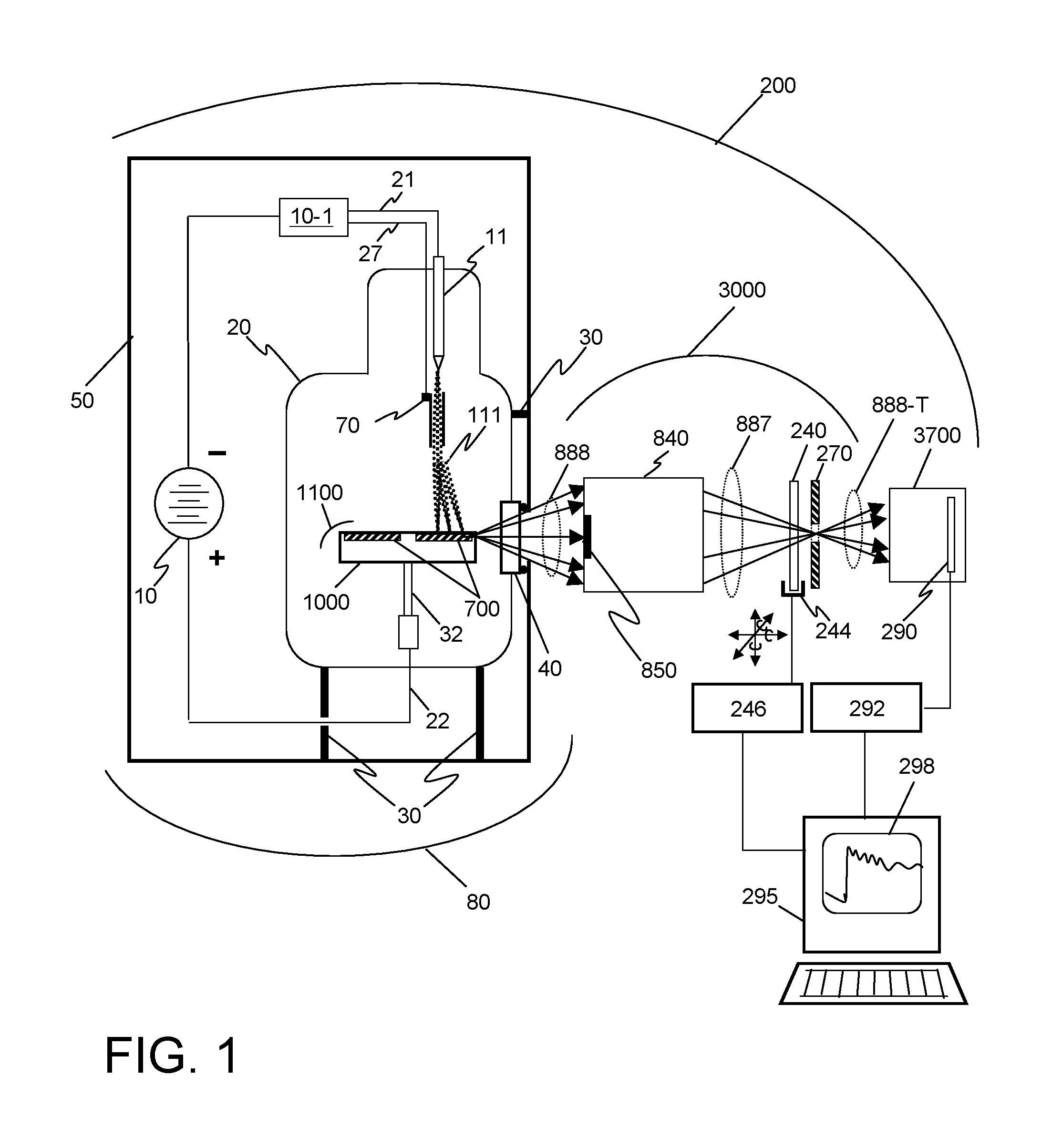
FIG. 1 illustrates a block diagram of an exemplary x-ray spectrometer system 200.
FIG. 2 illustrates an x-ray radiation spectrum.
FIG. 3 illustrates a portion of a target comprising three x-ray generating structures, each having a different x-ray generating material, as may be used in some embodiments of the invention.
FIG. 4A illustrates a cross section schematic view of an x-ray source and an optical system comprising an ellipsoidal optical element as may be used in some embodiments of the invention.
FIG. 4B illustrates a perspective schematic view of a portion of the x-ray source and optical system of FIG. 4A
FIG. 5A illustrates a cross section schematic view of an x-ray source and an optical system comprising a pair of paraboloidal optical elements as may be used in some embodiments of the invention.
FIG. 5B illustrates a perspective schematic view of a portion of the x-ray source and optical system of FIG. 5A
FIG. 6 illustrates a cross section schematic view of a spectrometer system using a single crystal analyzer according to the invention.
FIG. 7 illustrates a cross section schematic view of the spectrometer portion of the system illustrated in FIG. 11.
FIG. 8A illustrates a cross section schematic view of the spectrometer portion of a system similar to that illustrated in FIG. 11, but using a mosaic crystal.
FIG. 8B illustrates a schematic view of a spectrometer such as that illustrated in FIG. 13B, additionally arranged to show the related Rowland Circles.
FIG. 9 illustrates a perspective schematic view of a spectrometer system as may be used in some embodiments of the invention.
FIG. 10 illustrates a perspective schematic view of a spectrometer system having multiple options for x-ray source, optical system, aperture, and crystal analyzer position as may be used in some embodiments of the invention.
FIG. 11 illustrates a cross section schematic view of a spectrometer system using a single crystal analyzer according to the invention.
FIG. 12A presents a portion of the steps of a method for collecting spectroscopy data according to an embodiment of the invention.
FIG. 12B presents the continuation of the steps of the method of FIG. 12A for collecting spectroscopy data according to an embodiment of the invention.
FIG. 12C presents the continuation of the steps of the method of FIGS. 12A and 12B for collecting spectroscopy data according to an embodiment of the invention.
DETAILED DESCRIPTION
Instances of the present technology include an x-ray absorption spectrometer usable with a compact x-ray source (e.g., first source) to measure x-ray transmission with high throughput, high spatial, and high spectral resolution. In some instances, the spectrometer includes an x-ray optical system which achromatically focuses x-rays emerging from the x-ray source that preserves the brightness of the x-ray source and also serves as a low-pass filter with a predetermined high-energy cut-off for the x-rays. One major advantage of the use of an x-ray optical system serving as low-pass focusing reflector is that the accelerating voltage of the electrons of the x-ray source can be substantially higher than the predetermined high-energy cut-off, increasing the x-ray production efficiency to achieve high source brightness. This optical system can provide a point or a line focus that serves as the virtual source for x-rays in a spectrometer that includes of a crystal analyzer.
The x-ray optical elements in the train may include paraboloid optics, ellipsoidal optics, polycapillary optics, or various types of Wolter optics, Kirkpatrick-Baez mirrors or multilayers suitably graded and systems comprising combinations thereof. The high collection and focusing efficiency achievable using these optical elements helps achieve high flux density in tightly focused spots.
In some embodiments, the higher brightness compact x-ray source is achieved in part through the use of novel x-ray targets used in generating x-rays from electron beam bombardment. These x-ray target configurations may include a number of microstructures of one or more selected x-ray generating materials fabricated in close thermal contact with (such as embedded in or buried in) a substrate with high thermal conductivity, such that the heat is more efficiently drawn out of the x-ray generating material. This in turn allows bombardment of the x-ray generating material with higher electron density and/or higher energy electrons, which leads to greater x-ray brightness and greater x-ray flux.
An object to be examined in transmission is placed in the x-ray beam, and an aperture is placed at the point or line of focus to selectively pass the transmitted x-rays while restricting the widely radiated x-ray fluorescence and any scattered radiation that may exist. The object may be translated in x- and y-axes to allow a 2-D "map" of the transmission spectrum to be collected.
The aperture placed at the point or line of focus becomes the "source" (often referred to as the virtual source or second source) for a second x-ray optical system (the spectrometer) designed to disperse x-rays emerging from the aperture. This second system uses diffractive analyzer crystals to diffract x-rays of different energies onto an array detector, aligned so that different pixels of the detector correspond to different x-ray energies.
In some embodiments, an additional beam stop may be placed after the aperture to block the directly transmitted beam, but allow x-ray fluorescence emitted by the object to enter the spectrometer and be spectroscopically analyzed.
The present x-ray optical system may have several advantages. One or more optics of the x-ray optical system can be used as a low pass filter to cut out and/or reduce the energy of at least a portion of the x-rays provided by an x-ray source to provide a second source for directing at a target. Additionally, the x-ray optical system may allow selection of one of a plurality of optics. This interchangeability of sources based on a selected optic provides different spectrums that can be optimized for different tasks.
The present x-ray optical system also provides for high spatial resolution. The present system can interrogate a sample and raster scan the sample at a spatial resolution of 10 microns, for example. This degree of spatial resolution is much stronger than prior systems, which for example provide resolution at a millimeter level.
The present x-ray optical system further provides a sample holder or mount that can include multiple samples without requiring a door of the system to be opened, and wherein each sample can be positioned at a distance from the source other than at or close to the source. In some instances, the mount can receive one or more of a plurality of samples and positions at least one sample in the focused x-ray beam for analysis. This variable sample positioning is better suited to changes in temperature and/or the environment and therefore provides for more accurate analysis of the sample. Further, the sample can be micro-fluidic, allowing x-rays to flow through samples of a different material.
1. An Exemplary Spectrometer System.
FIG. 1 illustrates a block diagram of an exemplary x-ray spectrometer system 200. The spectrometer system 200 of FIG. 1 includes an x-ray source 80, an x-ray optical system 3000 that includes an object 240 to be examined by x-ray transmission, a spectrometer 3700 including detector 290, signal processing electronics 292, and an analysis system 295 having a display 298.
The exemplary x-ray source 80 (e.g., first source) includes a vacuum environment (typically 10.sup.-6 torr or better) commonly maintained by a sealed vacuum chamber 20 or active pumping. Vacuum chamber 20 can be manufactured with sealed electrical leads 21 and 22 that pass from the negative and positive terminals of a high voltage source 10 outside the tube to the various elements inside the vacuum chamber 20. The source 80 can include mounts 30 which secure the vacuum chamber 20 in a housing 50. The housing 50 may include shielding material, such as lead, to prevent x-rays from being radiated by the source 80 in unwanted directions.
Inside vacuum chamber 20, an electron emitter 11 is coupled through lead 21 to the negative terminal of a high voltage source 10, which serves as a cathode and generates a beam of electrons 111, for example by running a current through a filament. Any number of prior art techniques for electron beam generation may be used for the embodiments of the invention disclosed herein. Additional known techniques used for electron beam generation include heating for thermionic emission, Schottky emission (a combination of heating and field emission), emitters including nanostructures such as carbon nanotubes, and by use of ferroelectric materials.
A target 1100 includes a target substrate 1000 and x-ray generating structures 700, which can include one or more x-ray generating materials. Target 1100 is electrically connected to the opposite high voltage lead 22 via target support 32 to be at ground or a positive voltage relative to the electron emitter 11, thus serving as an anode. The electrons 111 accelerate towards the target 1100 and collide with it at high energy, with the energy of the electrons determined by the magnitude of the accelerating voltage. The collision of the electrons 111 into the target 1100 induces several effects, including the radiation of x-rays 888, some of which exit the vacuum chamber 20 and are transmitted through a window 40 designed to be transparent to x-rays.
In some instances, there can also be an electron control mechanism 70 such as an electrostatic lens system or other system of electron optics. Control mechanism 70 can be controlled and coordinated with the electron dose and voltage provided by the electron emitter 11 by a controller 10-1 through an additional lead 27. The electron beam 111 may therefore be scanned, focused, de-focused, or otherwise directed onto target 1100, which can include one or more x-ray generating structures 700 fabricated to be in close thermal contact with a substrate 1000.
Once x-rays 888 exit the x-ray source 80, a portion of the x-rays are collected by optical system 3000. Optical system 3000 can include one or more optical systems 840 having x-ray optical elements with axial symmetry. The elements of the optical system 840 reflect x-rays at grazing angles to focus a portion 887 of the x-rays onto an aperture component 270 having one or more apertures 272. The object 240 to be examined is typically placed in a mount 244 and positioned at the focus or just before the aperture 272. The mount may allow the object 240 to be translated and/or rotated so that different portions of the object 240 are illuminated by the x-ray beams 887, allowing different positions on the object 240 to be illuminated in a systematic scan or from several angles of incidence, with this motion controlled by a controller 246. X-rays propagating along the axis of the optical system that are not collected and focused may be blocked by a beam stop 850.
Once the focused portion of the x-rays 887 converge onto the object 240, the transmitted x-rays 888-T that also pass through the aperture 272 are collected by a spectrometer 3700. The spectrometer 3700 typically includes at least one dispersing x-ray crystal and an x-ray detector 290. The detector 290 will typically be an array detector, positioned to record the intensity of the dispersed x-rays as a function of position. Additional signal processing electronics 292 and analysis system 295 correlate the intensity signals to the corresponding x-ray energy. The analysis system 295 may additionally include a display 298. The detector 290 may also include sensors and electronics that serve as an x-ray spectrometer, analyzing both the number of x-ray fluorescence photons emerging from the object 240 as well as their energy.
Additional embodiments of x-ray sources have been described in U.S. Patent Applications "X-RAY SOURCES USING LINEAR ACCUMULATION" (U.S. patent application Ser. No. 14/490,672, filed Sep. 19, 2014 and now issued as U.S. Pat. No. 9,390,881), "X-RAY SOURCES USING LINEAR ACCUMULATION" (U.S. patent application Ser. No. 14/999,147, filed Apr. 1, 2016, and now issued as U.S. Pat. No. 9,543,109), and "DIVERGING X-RAY SOURCES USING LINEAR ACCUMULATION" (U.S. patent application Ser. No. 15/166,274 filed May 27, 2016), all of which are hereby incorporated by reference in their entirety, along with any provisional applications to which these Patents and co-pending Patent Applications claim benefit.
Any of the target and/or source designs and configurations disclosed in the above referenced Patents and Patent Applications may be considered for use as a component in any or all of the methods or systems disclosed herein. Such variations may include active cooling systems having channels that carry liquid near or into the target to remove heat, mechanisms to rotate the anode to allow different portions to be bombarded by electrons while other recently bombarded portions cool, systems including multiple electron beams that bombard opposite sides of a target to increase x-ray brightness through linear accumulation, and systems that additionally use multiple anodes aligned to create an x-ray beam through linear accumulation from several sources.
The components illustrated in the Figures are exemplary, and the various elements (microstructures, surface layers, cooling channels, etc.) are not intended to be limiting. It should also be noted that the x-ray source used for embodiments of the invention may be a microfocus, nanofocus, or rotating anode source using bombardment of a solid anode target by electrons, but that the target may also include multiple x-ray generating materials, and may additionally contain regions in which the x-ray generating materials are molten or liquid. Furthermore, the x-ray source may be any x-ray source designed to use a liquid metal (such as a gallium liquid metal jet) as the anode.
2. X-ray Source Spectrum.
FIG. 2 illustrates an x-ray radiation spectrum for 100 keV electron excitation with a tungsten (W) target. The broad spectrum x-ray radiation continuum 388, commonly called bremsstrahlung, is larger at lower energy and decreases at energies approaching the excitation energy of 100 keV. Characteristic lines 988 for tungsten are also illustrated.
This exemplary spectrum is modified for use in a spectroscopy system to limit the x-ray bandwidth. As discussed with respect to FIG. 1, the x-ray source 80 will typically have a window 40. This window 40 may attenuate low energy x-rays. Shown in FIG. 2 is a modified energy spectrum 488 for the x-rays that results from using an SiO.sub.2 window 100 microns thick. Some laboratory sources either come with a Be window (normally 200-300 um thick) or with a diamond window (normally .about.200-300 um thick), which also doubles up as a target substrate in the transmission source type. The system may additionally include a filter, such as a sheet or layer of aluminum, placed near the source or on the window to further attenuate low energy x-rays.
For a spectrometer, broad-spectrum x-rays can be used, and in some instances can be preferred, and characteristic lines 988 may make the task of interpreting the resulting spectra more difficult. It is therefore often advantageous to have the optical system collecting and focusing the x-rays designed to serve as a low-pass filter, severely attenuating any characteristic lines that may be generated and high energy bremsstrahlung background.
The optical system can include one or more x-ray optical elements in which the x-rays illuminates the inner surface of the element at a near-grazing angle (e.g. at angles of a few degrees or smaller). The optics may be coated with a particularly selected material, such that the critical angle of reflection can be exceeded for the higher energy x-rays, and the higher energy x-rays may not be efficiently reflected by the optical surface. As such, the x-ray optical system can have low-pass spectral filter properties such that x-rays above a cut-off energy are reduced as they pass through the optic system. X-rays below the cut-off energy may be focused to a predetermined focal plane.
Also in FIG. 2, a modified energy spectrum 588 that results from using a silver (Ag) coating on the interior of a capillary with a grazing angle of incidence of 3.5 mrad (0.2005 degrees), as calculated using the website henke.1bl.gov/optical_constants/layer2.html. X-ray energies above 17.4 keV are significantly attenuated, providing 17.4 keV as a "high-energy cutoff" for reflection in this system. This cuts out the strong tungsten characteristic lines at higher energy. When combined with the "high pass" filter provided by the window, the "low-pass" optical system provides a system with a predetermined x-ray "bandwidth".
The "high-energy" cutoff is well defined for a given material with a critical angle, and the attenuation of high energy x-rays prevents spurious signals from being observed at higher harmonics (e.g. twice (2.times.) the energy) downstream in the spectrometer. However, additional structure in the reflectivity spectrum may be observed at high energy with some materials. For some x-ray reflective optics, the reflectivity may be designed to be below 25% for all energies greater than 1.2 times the cutoff energy. For some x-ray reflective optics, the reflectivity may be designed to be below 10% for all energies greater than 1.2 times the cutoff energy.
3. Structured X-ray Source.
The x-ray bandwidth for a given x-ray source target material and combination of window/filter and x-ray optical system may or may not provide the full range of x-ray energies needed for the measurement of the x-ray absorption spectrum of a given object to be examined. Achieving enough x-ray brightness in the spectral region of interest may be an issue, and therefore, x-ray sources includes targets having x-ray generating materials embedded into a thermally conductive substrate. X-ray source material could include one of several types of sources, including a solid continuous target or a micro-structured target.
Microstructured targets, x-ray generating materials, x-ray target materials, microstructures of different shapes, and microstructures of various materials such as those that may be used in embodiments of the present technology disclosed herein are described in US Patent Application entitled "STRUCTURED TARGETS FOR X-RAY GENERATION" (U.S. patent application 14/465,816, filed Aug. 21, 2014), the disclosure of which is hereby incorporated by reference in its entirety along with any provisional Applications to which said Patent Application claims benefit.
Although the targets may be aligned to radiate x-rays using a zero-degree take-off angle, as discussed above, some embodiments may use near-zero degree take off angles using source configurations as presented in, for example, U.S. patent application Ser. No. 15/166,274, filed May 27, 2016 by the inventors of the present Application and entitled "DIVERGING X-RAY SOURCES USING LINEAR ACCUMULATION," which is hereby incorporated by reference into the present application in its entirety.
FIG. 3 illustrates a portion of a target comprising three x-ray generating structures, each having a different x-ray generating material. By translating the target along the width direction so that the electrons 111 now bombard this second set of microstructures, a second set of x-rays 1888 are produced. If the materials of the first set 710 and second set 720 are distinct, the corresponding x-rays 1788 and 1888 generated when selected for bombardment by electrons will also have distinct spectral properties.
Various targets include different x-ray generating materials may be used in various embodiments. As illustrated in FIG. 3, multiple solid structures 740, 750 and 760 of different x-ray generating materials may be used in an anode target as well, with selection between target materials made by translation of the target under the electron beam 111 to select, for example, the third material 760, generating the corresponding x-rays 1688.
Although the physical translation of the target under the electron beam may allow the materials to be "switched" from one to another while producing a beam that remains aligned with a single set of x-ray optics, other embodiments in which the electron beam is simply directed from one set of materials to another may also be used. This may be beneficial in cases where the different x-ray generating materials are aligned with different sets of x-ray optics, with each set of optics tuned to match the radiation spectrum of x-rays for each material. Directing the electron beam from one to the other therefore allows rapid switching between spectral sources.
4. X-ray Optical System.
Once x-rays are generated by a high-brightness x-ray source, a portion of the x-rays can be collected by an optical system to be subsequently collimated and/or focused onto the object to measure the x-ray absorption and transmission.
Optical systems used in embodiments of the invention disclosed herein have been described in detail in the U.S. Patent Application entitled "X-RAY ILLUMINATORS WITH HIGH FLUX AND HIGH FLUX DENSITY" (U.S. patent application Ser. No. 15/431,786, filed Feb. 14, 2017) and its parent Applications (U.S. patent applications Ser. No. 15/269,855, filed Sep. 16, 2016, and now issued as U.S. Pat. No. 9,570,265, and 14/544,191, filed Dec. 5, 2014 and now issued as U.S. Pat. No. 9,449,781), which are all hereby incorporated by reference in their entirety, along with the provisional Applications to which they claim benefit.
Referring to FIG. 1, the generated x-rays will diverge from the x-ray source 80, and after passing from the source through an x-ray transparent window 40, an optical system 3000 includes a set of one or more x-ray optical elements will intersect a portion of the x-rays and redirect their path of propagation.
The optical system 3000 may be a simple, single x-ray reflecting optical element with the topology of a hollow tube, or a more complex set of x-ray optics. This optical system 3000 can be mounted along the axis of brightest illumination so that a portion of the diverging x-rays 888 will reflect off the inner surface of the various optical elements. The curvature of the inner and/or inner and outer surface may take a number of geometric forms, but a very useful set of geometric forms for a number of optical elements are found among the quadric surfaces, and in particular, spheroids, ellipsoids, paraboloids, hyperboloids, elliptic cylinders, circular cylinders, elliptic cones, and circular cones. In some instances, at least a portion of a reflective surface of the reflective x-ray focusing optic is axially symmetric. In some embodiments, the reflective surface may be coated with a material selected for its x-ray reflective properties, including its critical angle. Such materials may include chromium, copper, rhodium, palladium, gold, silver, nickel, iridium, and platinum, among others.
These optical elements will typically be mounted such that a portion of the x-rays experience total external reflection from the inner surface, as was described above. The reflected x-rays from an individual optical element may be focused to a point or a line, or collimated, or configured to produce some other diverging or converging wavefront, but for the embodiments presented here, the optical system produces a converging wavefront of x-rays 887 that comes to a focus at an aperture 272.
By placing an object 240 to be examined where it will be illuminated by the converging x-rays 887, a transmitted diverging x-ray wavefront 888-T is produced on the far side of the aperture 272, and may be subsequently analyzed by the spectrometer.
4.1. Optics Configurations
Optical configurations for use with the present technology can be configured as an ellipse, parabola, paraboloidal, or other shape. FIGS. 4A-5B illustrate exemplary optical reflectors.
FIG. 4A illustrates in cross section a possible optical configuration for the optical system using the form of an ellipse. An ellipse has two foci F.sub.1 and F.sub.2 such that any photons radiating from one of the foci will be reflected and converge onto the other. By configuring the inner surface of a tube-shaped optical element 3010 to have an ellipsoidal surface, and choosing the coating for the reflecting portion of the tube such that the angle of incidence for x-rays within a designated bandwidth emerging from the x-ray source is smaller than the critical angle, total external reflection is achieved. Then, at least a portion of the x-rays generated by an x-ray source placed at one of the foci will be focused to the other focus.
FIGS. 4A and 4B illustrate a portion of an embodiment of the invention utilizing such an ellipsoidal reflector 3010. An x-ray source includes x-ray generating microstructures 1700 embedded in a substrate 1000 generate x-rays 888 when bombarded by electrons 111 in a vacuum. The diverging x-rays 888 pass through a window 40 and enter the ellipsoidal optical element 3010. A portion of the x-rays experience total external reflection from the inner elliptical surface of a tube-like optical element 3010, and become focused x-rays 887 that converge onto an aperture 272 in an aperture component 270 after passing through the object 240 to be examined. In some embodiments, the on-axis x-rays may be blocked with a beam stop 1850. In some embodiments, as illustrated in FIG. 4A and the corresponding perspective view of FIG. 4B, the on-axis x-rays may be blocked with a beam stop 1850.
FIGS. 5A and 5B illustrate a portion of an embodiment of the invention utilizing a paraboloidal reflector 3020. An x-ray source includes x-ray generating microstructures 1700 embedded in a substrate 1000 generate x-rays 888 by linear accumulation when bombarded by electrons 111 in a vacuum. A parabola has single focus F.sub.p such that any photons radiated from the point of focus will be reflected to form a parallel (collimated) beam. The diverging x-rays 888 pass through a window 40 and enter the first paraboloidal optical element 3020. A portion of the x-rays experience total external reflection from the inner paraboloidal surface of the tube-like optical element 3020, and become collimated x-rays 889.
Once collimated, a second optical element 3022 with a tube-shaped topology and paraboloidal inner surface, as shown in FIGS. 5A and 5B, may be aligned with the optical axis of the first optical element 3020 so that the collimated x-rays 889 are incident on the inner surface of the second optical element 3022 at angles smaller than the critical angle for the surface. The reflected x-rays then become focused x-rays 887 that converge onto an aperture 272 after passing through the object 240 to be examined.
Although the illustration shows a second paraboloidal optical element 3022 of the same size and shape as the initial paraboloidal optical element 3020, these need not be the same dimensions, but may have paraboloid surfaces with different curvature and relative focus positions.
In some embodiments, as illustrated in FIG. 5A and the corresponding perspective view of FIG. 5B, the on-axis x-rays may be blocked with a beam stop 1852. Although shown positioned between the two paraboloidal optical elements, the beam stop may be at the entrance to the first optical element 3020, or at the exit of the second optical element 3022 as well.
4.3. Other X-ray Optics.
Other x-ray optical systems, such as Wolter Type I optics, cone shaped capillary optics, Kirkpatrick-Baez optics, etc. may be used as components of the optical system. Systems including filters and additional beam stops, etc. may also be used.
The optical elements described above may be fabricated of any number of optical materials, including glass, silica, quartz, BK7, silicon (Si), Ultra-low expansion glass (ULE.TM.), Zerodur.TM. or other materials.
The reflective coatings used for the various optical elements used in embodiments of the invention as described above may be of a single elemental material, to take advantage of the total external reflection for angles of incidence smaller than the critical angle, and preferably may be of higher mass density material (greater than 2.5 g/cm.sup.3) at least 25 nm thick. Materials such as gold (Au), silver (Ag), platinum (Pt), etc. may be used as single-material coatings for these optical elements.
The reflective coatings may also be multilayer coatings, with alternating periodic layers of two or more materials, that provide constructive interference in reflection for certain x-ray wavelengths. The reflection efficiency depends on the wavelength and angle of incidence of the x-rays as well as the thickness of the alternating layers and number of layers, so this has limited use as a broadband reflector, but may be used if specific wavelengths are desired. A multilayer could also be depth graded and so the energy bandwidth could be "reasonably large," such as for example 20-25% bandwidth has already been demonstrated for hard x-rays.
Combinations that may be used for multilayer reflectors may be tungsten/carbon (W/C), tungsten/silicon (W/Si), tungsten/tungsten silicide (W/WSi.sub.2), molybdenum/silicon (Mo/Si), nickel/carbon (Ni/C), chromium/scandium (Cr/Sc), lanthanum/boron carbide (La/B.sub.4C), tungsten/boron carbide (W/B.sub.4C), and tantalum/silicon (Ta/Si), nickel/boron carbide (Ni//B.sub.4C), and aluminum/alumina (Al/Al.sub.2O.sub.3), among others. The surface may also be a compound coating that includes an alloy or mixture of several materials.
Other optical elements, such as Fresnel Zone Plates, cylindrical Wolter optics, Wolter Type II optics, Kirkpatrick-Baez mirrors, Wolter Type III optics, Montel optics, diffraction gratings, crystal mirrors using Bragg diffraction, hole-array lenses, multi-prism or "alligator" lenses, rolled x-ray prism lenses, "lobster eye" optics, micro channel plate optics, or other x-ray optical elements may be used or combined with those already described to form compound optical systems for embodiments of the invention that direct x-rays in specific ways that will be known to those skilled in the art.
5.0 Basic Spectrometer.
FIGS. 6-9 illustrate schematic cross-section views and a perspective view the elements of a spectrometer system that may be used in some embodiments of the invention. Turning to FIG. 6, the x-ray target 1100 includes a substrate 1000 and x-ray generating material 1700 bombarded by electrons 111 in a vacuum. As drawn, the x-rays 888 emerge at a non-zero take-off angle relative to the surface, but other alignments using a zero-degree take-off angle may be used as well.
The x-rays 888 that diverge from the x-ray source pass through the window 40 in the vacuum chamber, and are collected by an optical system. In the example of FIGS. 6-9, the optical system includes a single ellipsoidal capillary optic 3010 and a beam stop 1854. This single optic 3010 has an inner surface that reflects x-rays at near-grazing angles and focuses them onto the aperture 272 in the aperture component 270. An object 240 to be examined is positioned before the aperture component 270, and the x-rays passing through the aperture 272 are those that have been transmitted through the object 240.
The aperture 272 will typically be a small hole of a diameter comparable to the size of the focused spot produced by the x-ray optical system. Aperture diameters of 5 to 25 microns may be typical in some embodiments of the invention. In some embodiments of the invention, the aperture may include a slit, in some instances generally oriented horizontally. The size of the aperture will generally be designed to correspond to the expected size and dimensions of the focused x-ray beam. The aperture component itself may include a piece of metal (e.g. molybdenum or platinum) having a thickness shorter than the depth of focus for the optical system (e.g. on the order of 20 microns thick).
On the far side of the aperture component 270, the x-rays emerge from the focus and are again diverging x-rays 888-T. The geometry will generally be an annulus of x-rays, as defined by the exemplary x-ray optic 3010. As shown, the aperture 272 serves as the point of origin for the x-rays entering the spectrometer 3700. Additional aperture(s) may also be used within the spectrometer to further block scattered x-rays.
In the spectrometer, the cone of x-rays 888-T will fall onto the surface of a diffracting crystal analyzer 3710, which will diffract x-rays of different wavelengths .lamda..sub.1, .lamda..sub.2, .lamda..sub.3 .lamda..sub.4, etc. (shown as ray bundles 887-A, 887-B, 887-C, and 887-D etc., respectively) to different points on an array detector 290. As shown in FIG. 5 and, in more detail in FIG. 6, the crystal analyzer will act as a Bragg diffraction element, reflecting the x-rays if the correct conditions of wavelength and angle of incidence are met. X-rays that are not diffracted 899 are typically transmitted through the crystal analyzer, and may be absorbed by a beam stop (not shown) or by the crystal, or by the crystal's mount.
In some instances, multiple crystals can be used in the x-ray spectrometer. When more than one crystal is used, each of the crystals may be selected based on monochromaticity requirements.
The crystal analyzer 3700 may be positioned .about.250 mm away from the aperture 272, and will typically have a width of about 1 cm. and a length smaller than 5 cm., but other dimensions may be used. The crystal analyzer 3700 may include a single planar Bragg crystal, but in practice, the crystal analyzer may be a thin crystal curved in the sagittal direction. This allows the x-rays diverging in the directions perpendicular to the direction of propagation to be collected and focused onto the detector 290, while allowing the x-rays to be diffracted by wavelength along the direction of propagation. For some embodiments, a bending radius between 50 and 200 mm may be used. Such configurations are sometimes called a von Hamos Spectrometer.
Curved crystal analyzers such as those made from thin wafers of single crystal silicon with (111) and (220) planes parallel to the surface may be used in some embodiments of the invention. Single crystal silicon analyzers may be grown onto a curved substrate or bent and glued to a similarly shaped substrate.
In some instances, crystal analyzers can include graphite, highly oriented pyrolytic graphite (HOPG), or highly annealed pyrolytic graphite (HAPG). These embodiments may be produced by growing a graphite layer (e.g., 5 and 200 microns thick) onto a curved substrate.
FIGS. 8A and 8B illustrate a spectrometer 3730 using a crystal analyzer in the form of a mosaic crystal 3733. In the mosaic crystal 3733, the crystal analyzer includes an ensemble of micro-crystals at varied angles throughout the material, each as small as a few hundred nanometers or as large as several microns, held with a backing 3734, typically made of metal. Transmitted x-rays that were not diffracted by the micro-crystal at the surface may still be diffracted from another micro-crystal positioned deeper within the mosaic.
Although the entire spectrum of x-rays transmitted through the object 240 will be present at all points of the transmitted annulus of x-rays 888-T, dispersion is achieved because the diverging cone has a variety of angles of incidence on the crystal analyzer, and therefore for at least some angle of incidence, x-rays of a particular energy within the designated x-ray bandwidth may be reflected. However, all other wavelengths at the same angle of incidence will not be diffracted, and will be partially or completely absorbed by the crystal analyzer shown as transmitted x-rays 899 in FIGS. 5 and 6).
FIG. 8B illustrates the relationship for which additional collection of x-rays may occur. The origin (the aperture in this case), the diffracting crystal, and the point of convergence at the detector all fall along the Rowland Circles 808-A and 808-D for the corresponding wavelengths. Although other micro-crystals are present in the mosaic crystal, only those that lie along the Rowland Circle and have the correct orientation will diffract x-rays to converge to the same position at the detector 290. X-rays of varying wavelengths distributed throughout the diverging beam 888-T have a better chance of encountering a properly positioned and oriented micro-crystal, increasing the number of x-rays directed towards the detector. Use of mosaic crystals can collect as much as 30 times the amount of x-rays that a single crystal diffraction element can produce.
FIG. 8B includes the elements of FIG. 8A, but additionally shows the Rowland Circles 808-A and 808-D for the two x-ray wavelengths, and also only illustrates representative micro-crystals on the mosaic crystal contributing to the diffraction for the two wavelengths. Although micro-crystals with "random" orientations are illustrated in FIG. 8A to dramatically illustrate the mosaic non-uniformity, most mosaic crystals will be more closely aligned with the Bragg angles at the angles of incidence for which they are designed.
FIG. 9 illustrates a schematic perspective view of a system using a curved crystal analyzer having a mosaic crystal that distributes the spectrum along one axis, while focusing x-rays in the other (sagittal) axis. As noted before, it should be clear that the drawings presented here are not illustrated to scale, but have been created to better point out how the invention is to be made and used.
For more on crystal or multilayer reflectors, see James H. Underwood, "Multilayers and Crystals", Section 4.1 of the X-ray Data Booklet, which may be downloaded at: xdb.1bl.gov/Section4/Sec_4-1.pdf, and which is hereby incorporated by reference.
5.2. Detectors.
The detector 290 typically includes a 2-D pixel array 294, in which one axis is significantly longer than the other. A 2048.times.256 pixel array may be typically used, although a detector with at least 128 pixels along the long axis (the dispersive direction) may be preferred. For some configurations where the beam cross sections are smaller and the distances are shorter, fewer pixels may be used. Also, if a portion of the beam is to be blocked, fewer pixels may be used. The long axis will be aligned along the direction of x-ray propagation, and the dispersion of x-rays by wavelength will occur along that axis. The short axis will be aligned with the sagittal direction. The diffracted x-rays may not form a perfect spot, and so detection using multiple pixels may provide a higher collection efficiency.
The detector may be any one of a number of x-ray array detectors, such as a CCD array, a CMOS or S-CMOS detector, a flat panel sensor, or any one or more position sensitive x-ray array detectors known in the art that converts x-ray intensity to an electronic signal, including 1-D line and 2-D array detectors. Such examples of position-sensitive detectors include linear detectors, position-sensitive array detectors, pin diodes, proportional counters, spectrometers, photodiode detectors, scintillator-type and gas-filled array detectors, etc.
Energy resolving pixel array detectors may also be used. In these detectors, each pixel also provides information on the energy of x-rays detected, and may be especially useful when the object produces significant fluorescence. Also known as energy resolving x-ray spectrometer, such a detector uses a semiconductor device to measure the energy of the detected x-ray photons. The silicon PIN photodiode (Si-PIN) is a simple and low cost class of EDS spectrometer that typically has the lowest performance in terms of energy resolution. Energy resolving pixel array spectrometers are available and may be used in some embodiments of the invention.
Another type of detector, known as a pixel array microcalorimeter spectrometer, uses typically a superconductor circuit to measure change of the electric response from absorption of an x-ray photon.
In some instances, the spectrometer may include a mechanism, such as a shielding component, that prevents undesired x-rays from being detected. For example, at least one x-ray shielding component can be implemented that prevents x-rays not-dispersed by the wavelength dispersive component from arriving at the detector.
Additional configurations may involve additional filters (e.g. thin foils containing the appropriate element(s)) along the beam path before the detector to preferentially attenuate some unwanted x-rays from arriving at the spectrometer, reducing the background due to the detection of the x-rays scattered from the object or reduce total x-ray flux entering the spectrometer to avoid saturation. Multiple spectrometers of the same type or combination of two or more types can be used simultaneously or interchangeable to utilize their respective strength individually or collectively.
Other detector geometries and arrangements may be known to those skilled in the art. For more on x-ray detectors, see Albert C. Thompson, "X-Ray Detectors", Section 4.5 of the X-ray Data Booklet, which may be downloaded at: xdb.1bl.gov/Section4/Sec_4-5.pdf which is also hereby incorporated by reference.
5.3. Options and Versatility.
As discussed above, a single x-ray generating material combined with a selected coating for an x-ray optic may provide a limited bandwidth for an x-ray optical system that avoids unwanted characteristic lines and provides a particular region of an absorption spectrum for an object to be investigated. However, any given x-ray generating material with any given optical coating will generally not provide the full spectral range needed to characterize an object in transmission.
FIG. 10 provides a schematic illustration of a spectrometer system having a diversity of options built into the system. The target 1102 includes a substrate 1002 and two (or more) different types of x-ray generating materials 1702 and 1704. The mount 34 upon which the target is secured not only connects to the electrical lead 32, but also has a controller 36 that allows physical motion in a lateral direction for the selection of the material to be bombarded by electrons 111.
The system of FIG. 10 also has three different optical systems 3010-A, 3010-B and 3010-C supported in a mount 3016 that allows the set of optical systems to be moved laterally to allow alignment of any of the optical systems (which may use different material coatings and filters inside to allow different x-ray bandwidths) with any of the x-ray generating targets 1702, 1704 etc. As illustrated, the rightmost x-ray generating material 1704 is being bombarded by electrons, and the left most optical system 3010-A is positioned to collect the x-rays transmitted through the window 40.
As before, the converging x-rays 887 emerging from the optical system are focused onto an aperture 272 in an aperture component 270, and also pass through the object 240 to be investigated. The resulting x-rays diverging from the aperture 272 become the "virtual origin" for the x-rays diffracted by the spectrometer 3700.
However, the aperture component 270 may have multiple openings, such as circular apertures 272 and 274 having different sizes, or slits 275 and 277 of different sizes.
As before, the spectrometer 3731 includes a mosaic crystal analyzer 3733 that disperses the x-rays onto the x-ray sensor 294 of the detector 290. However, in case the wavelength range is insufficient to span the entire spectrum in a single shot, this spectrometer 3731 also includes a mount 3740 that allows the crystal analyzer 3710, an x-ray wavelength dispersive element, to rotate about an axis perpendicular to the direction of x-ray propagation. This allows a larger range of x-ray dispersion to be measured using a single detector.
Such a multi-source/multi optic system may be used to collect x-ray spectra in a sequence of bands. For example, a first measurement may be taken using a source/optic combination to provide an x-ray spectrum between 4 and 5 keV; the next a different combination to provide a spectrum between 5 and 6 keV; and the next a third combination to provide a spectrum between 6 and 7 keV, etc. Rotation of the crystal about the axis may expand the range of energies collected from the same source/optic combination.
In other variations, optical systems with a variety of beam stops may be used. Beam stops may be positioned at the entrance to the optical system, at the exit of the optical elements of the optical system, or in between elements of the optical system. In some embodiments with a single condenser optic, there may be a stop on both the entrance side and the exit side of the condenser optic, with the exit-side stop being .about.2/3 the size of the entrance stop. These stops will both block the through-beam, and in addition, the exit stop will also block a good portion of any scattered x-rays from the condenser optic. This provides for a cleanly reflected x-ray beam.
In other variations, a number of shielding elements may be used to block or reduce unwanted x-rays from being detected. Scattering and x-ray fluorescence may occur every time x-rays encounter a component of the system. Likewise, x-rays not diffracted by the crystal analyzer will be transmitted through the analyzer, and may create additional scattered and/or fluorescence x-rays unless a suitable beam absorbing element is positioned behind the analyzer. Although these unwanted x-rays will not propagate along the principle beam-path of the system in the way that the focused x-rays propagate, they may still find their way through the system and onto a detector element unless additional shielding is installed.
In other variations, the entire system (and not just the x-ray source) may be enclosed in a vacuum chamber, removing the need for the window 40 be present to maintain the vacuum around the x-ray source. Likewise, the optical system and spectrometer may be flushed with helium gas, to reduce scattering in the system.
5.4. X-ray Emission Spectroscopy (XES).
Another embodiment adapted to detect the spectrum of x-ray fluorescence for use in x-ray emission spectroscopy (XES) is shown in FIG. 11. The embodiment of FIG. 11 is similar to the configuration illustrated in FIG. 6, except the object 240-F emits x-ray fluorescence 877. This fluorescence will generally be emitted in all directions from the object 240-F. Therefore, to block the x-rays 888-T directly transmitted through the object 240-F, a beam stop 254 is positioned after the aperture component 270, and only the x-ray fluorescence 877 emerging from the object 240-F around the beam stop 254 propagates onward to the crystal analyzer 3710. The crystal analyzer 3710 then disperses the fluorescence according to wavelength, with x-rays 877-A, 877-B, 877-C, 877-D, etc. of different wavelengths directed to different positions on the detector sensor 294.
6.0 Methods of Spectroscopic Data Gathering.
The process steps to measure the transmission spectrum of an object according to an embodiment are represented in FIGS. 12A, 12B, and 12C, and are described below.
In the first step 4610 an object to be examined is selected, and the x-ray spectral range over which transmission information is desired is selected. The object may be any type of object, as long as a significant number of detectable x-rays are transmitted through the object.
In the next step 4620, an x-ray target that will produce x-rays in the spectral range when bombarded by electrons is selected. This may include a target with any number of x-ray generating materials that have been mentioned in the Patent Applications cited above, including tungsten, molybdenum, copper, rhodium, etc. The target may include a single x-ray generating material, or multiple x-ray generating materials, and may function in the x-ray source as a static or as a rotating anode.
In the next step 4630, a reflective x-ray focusing optic or optical system is selected that has a particular high-energy cutoff. This may arise from the material of the optic itself, reflective coating that have been applied to the optic or optical elements, or filters that are a part of the optical system.
The focusing optic will be designed to collect x-rays and focus them to a particular focal plane, and so in the next step 4640, the position in space where this focus plane will occur will be determined. This may be set by simply placing the optic into a predetermined position, or may require some alignment and adjustment of the position of the optic and the target within x-ray source, as noted in step 4660. Before this step is carried out, however, a decision step 4644 occurs, in which a decision is made as to whether an aperture or slit in the focal plane should be used. If the decision is yes, then a step 4650 in which the aperture or slit is positioned in the focal plane is carried out before the subsequent alignment step 4660.
Once the position of the x-rays in the focal plane (or the location of the aperture/slit) has been determined, the crystal analyzer is aligned to collect x-rays emerging from the focal plane (or aperture/slit, if used) and disperse them. The crystal analyzer may be any analyzer as described previously, including a single crystal structure, a mosaic crystal, etc.
In the next step 4680, the x-ray detector, generally a 2-D array detector as described above, will be placed to detect the x-rays dispersed by the crystal analyzer. This step will typically complete the alignment phase of the method, and the method proceeds to the steps shown in FIG. 12B, with the handoff designated by the circled X in the figures.
Referring now to FIG. 12B, in the next step 4810, the electrons bombard the target and x-rays are generated.
In the next step 4820, the transmission x-ray spectrum of the instrument (without the object in the optical path) is recorded. This serves as the reference data against which the subsequent measurements will be made.
In the following steps, the object will be positioned to be illuminated by x-rays. A decision 4822 to use or not use a shutter to block the beam made, and, if positive, the shutter is used to block the beam in step 4830, and in the next step 4840 the object may be positioned without the x-rays illuminating the object. Once positioned, the next step 4850 unblocks the x-ray beam, allowing the object to be illuminated by the x-rays. If the shutter is not used, then in step 4844 the object may be positioned while the x-rays beam is still on.
Once the x-rays illuminate the object, in the next step 4860 the x-rays transmitted through the object and then dispersed by the spectrometer are detected by the detector sensor and recorded.
Now that an x-ray transmission for the system with and without the object have been recorded, in the next step 4870 the two results may be compared, and the results of the comparison may be used to calculate the transmission spectrum of the object in the following step 4880. From the transmission results, the absorption spectrum of the object may also be inferred.
The transmission spectrum so generated represents the spectrum of the object at a single point of illumination in the object for a single x-ray bandwidth range (selected by the choice of optic and target in the previous steps). The method then proceeds to the next steps, represented by the circled Y in the FIGS. 12B and 12C, in which alternative variations of the data may be collected.
In the next step 4882, it is determined whether information about additional points in the object need be collected; i.e. is there a "scan" of the object desired that forms a "map" of the spectral properties of the object. If so, the new position coordinates for the object are provided in the next step 4885, and the path of control proceeds to the position marked with a circled B in FIG. 12C and back to FIG. 12B, where the process of steps 4822 4844, 4830, 4840, 4850, 4860, 4870, 4880 and 4882 are repeated in a loop until the entire desired areal dataset for the object has been completed.
If the dataset is complete, the next step 4888 determined whether the data collected will be a 2-D dataset (representing, for example, a planar "map" of the object) or if a 3-D representation of the object for analysis, using algorithms related to, for example, laminography or tomography, may be required. If 3-D data for this energy range is desired, the process determined in the next step 4892 whether in fact the 3-D data collection is complete. If not, the settings for a different relative rotational orientation for the object relative to the x-rays are determined in the next step 4895, and control proceeds to the position marked with a circled B in FIG. 12C and back to FIG. 12B, where the process of steps 4822 4844, 4830, 4840, 4850, 4860, 4870, 4880, 4882, 4885, 4888, 4892, and 4895 are repeated in a loop until the entire desired 3-D dataset for the object has been completed.
Once the 2-D and/or 3-D data collection has been completed, in the next step 4900 it is determined whether additional information for a different x-ray spectral range is required. If the collected dataset is adequate, the process ends. Data collection is complete.
If, on the other hand, additional spectral data is required, in the next step 4950 a new spectral range is determined, and control passes through the path marked with the circled A in FIG. 12C and back to FIG. 12A, where the process beginning with step 4620 repeats using the new spectral range.
Variations on the method described above may also be put into practice. For example, instead of first executing a loop of data collection in x- and y-dimensions at a fixed rotation position, and then changing the rotation setting to collect additional data, embodiments in which the object is rotated while the x- and y-position settings remain fixed may also be executed. Rotation of the object around the z-axis may also provide additional information that can be used in image tomosynthesis. Likewise, data for various spectral ranges may be collected with or without the completion of 2-D or 3-D scans.
7. Limitations and Extensions.
With this Application, several embodiments of the invention, including the best mode contemplated by the inventors, have been disclosed. It will be recognized that, while specific embodiments may be presented, elements discussed in detail only for some embodiments may also be applied to others. Also, details and various elements described as being in the prior art may also be applied to various embodiments of the invention.
While specific materials, designs, configurations and fabrication steps have been set forth to describe this invention and the preferred embodiments, such descriptions are not intended to be limiting. Modifications and changes may be apparent to those skilled in the art, and it is intended that this invention be limited only by the scope of the appended claims.
Elements as shown in the drawings are meant to illustrate the functioning of various embodiments of the invention, and should not be assumed to have been drawn in proportion or to scale. Likewise, any single figure should not be construed as being an illustration showing all elements of any particular embodiment of the invention.
* * * * *
References
D00000
D00001
D00002
D00003
D00004
D00005
D00006
D00007
D00008
D00009
D00010
D00011
D00012

D00013
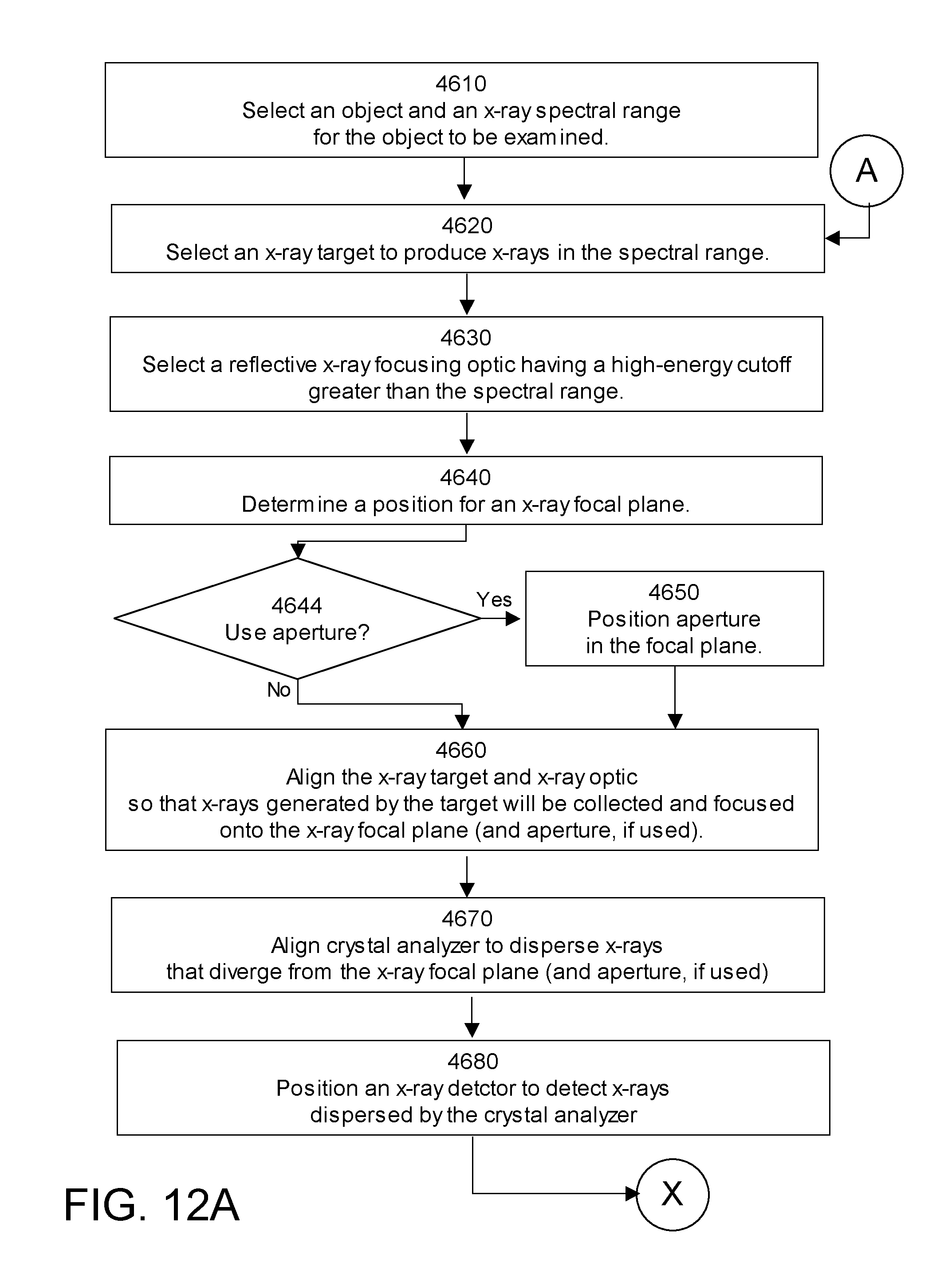
D00014

D00015

XML
uspto.report is an independent third-party trademark research tool that is not affiliated, endorsed, or sponsored by the United States Patent and Trademark Office (USPTO) or any other governmental organization. The information provided by uspto.report is based on publicly available data at the time of writing and is intended for informational purposes only.
While we strive to provide accurate and up-to-date information, we do not guarantee the accuracy, completeness, reliability, or suitability of the information displayed on this site. The use of this site is at your own risk. Any reliance you place on such information is therefore strictly at your own risk.
All official trademark data, including owner information, should be verified by visiting the official USPTO website at www.uspto.gov. This site is not intended to replace professional legal advice and should not be used as a substitute for consulting with a legal professional who is knowledgeable about trademark law.