Camera-based authorization extension system
Buibas , et al.
U.S. patent number 10,282,720 [Application Number 16/138,278] was granted by the patent office on 2019-05-07 for camera-based authorization extension system. This patent grant is currently assigned to ACCEL ROBOTICS CORPORATION. The grantee listed for this patent is ACCEL ROBOTICS CORPORATION. Invention is credited to Marius Buibas, Martin Alan Cseh, Kaylee Feigum, Michael Brandon Maseda, Csaba Petre, John Quinn.


View All Diagrams
| United States Patent | 10,282,720 |
| Buibas , et al. | May 7, 2019 |
Camera-based authorization extension system
Abstract
A system that analyzes camera images to track a person from a point where the person obtains an authorization to a different point where the authorization is used. The authorization may be extended in time and space from the point where it was initially obtained. Scenarios enabled by embodiments include automatically opening a locked door or gate for an authorized person and automatically charging items taken by a person to that person's account. Supports automated stores that allow users to enter, take products and exit without explicitly paying. An illustrative application is an automated, unmanned gas station that allows a user to pay at the pump and then enter a locked on-site convenience store or a locked case with products the user can take for automatic purchase. Embodiments may also extend authorization to other people, such as occupants of the same vehicle.
| Inventors: | Buibas; Marius (San Diego, CA), Quinn; John (San Diego, CA), Feigum; Kaylee (San Diego, CA), Petre; Csaba (San Diego, CA), Maseda; Michael Brandon (San Diego, CA), Cseh; Martin Alan (San Diego, CA) | ||||||||||
|---|---|---|---|---|---|---|---|---|---|---|---|
| Applicant: |
|
||||||||||
| Assignee: | ACCEL ROBOTICS CORPORATION (La
Jolla, CA) |
||||||||||
| Family ID: | 66333883 | ||||||||||
| Appl. No.: | 16/138,278 | ||||||||||
| Filed: | September 21, 2018 |
Related U.S. Patent Documents
| Application Number | Filing Date | Patent Number | Issue Date | ||
|---|---|---|---|---|---|
| 16036754 | Jul 16, 2018 | ||||
| Current U.S. Class: | 1/1 |
| Current CPC Class: | G06K 9/00201 (20130101); G08B 13/24 (20130101); G06Q 20/40 (20130101); G06K 9/00771 (20130101); G06T 7/251 (20170101); G06T 7/277 (20170101); G07G 3/003 (20130101); G06K 9/00335 (20130101); G06Q 20/3224 (20130101); G06N 7/005 (20130101); G06N 3/08 (20130101); G07F 19/207 (20130101); G06Q 20/204 (20130101); G06T 7/254 (20170101); G07F 13/025 (20130101); G06K 9/00342 (20130101); G06Q 20/18 (20130101); G06K 9/627 (20130101); G08B 25/08 (20130101); G06T 2207/10016 (20130101); G06T 2207/30196 (20130101); G06T 2207/20081 (20130101); G06T 2207/30241 (20130101); G06K 2009/3291 (20130101); G06T 2207/20076 (20130101); G06T 2207/30232 (20130101); G06T 2207/20084 (20130101) |
| Current International Class: | G06K 9/00 (20060101); G06N 3/08 (20060101); G06K 9/62 (20060101); G06Q 20/18 (20120101); G06Q 20/20 (20120101); G06Q 20/40 (20120101); G06T 7/246 (20170101) |
References Cited [Referenced By]
U.S. Patent Documents
| 6193154 | February 2001 | Phillips et al. |
| 6364206 | April 2002 | Keohane |
| 6882900 | April 2005 | Terranova |
| 8300890 | October 2012 | Gaikwad et al. |
| 9911290 | March 2018 | Zalewski |
| 9996818 | June 2018 | Ren et al. |
| 1004492 | August 2018 | Bradski et al. |
| 10055853 | August 2018 | Fisher |
| 2006/0279630 | December 2006 | Aggarwal |
| 2007/0282665 | December 2007 | Buehler et al. |
| 2008/0181507 | July 2008 | Gope et al. |
| 2009/0057068 | March 2009 | Lin |
| 2011/0317016 | December 2011 | Saeki et al. |
| 2012/0113294 | May 2012 | Oyabu et al. |
| 2015/0039458 | February 2015 | Reid |
| 2016/0358145 | December 2016 | Montgomery |
| 2017/0309136 | October 2017 | Schoner |
Other References
|
Swift Local Solutions, "What is frictionless shopping and how will it impact your retail business", Apr. 25, 2017 (6 pages). cited by applicant . Stores NRF's Magazine, "Standard Cognition makes frictionless checkout a reality", Jan. 23, 2018 (3 pages). cited by applicant . Porikli, Fatih, "Inter-Camera Color Calibration by Correlation Model Function", Mitsubishi Electric Research Lab, Cambridge, MA, 2003, 4 pages. cited by applicant. |
Primary Examiner: Fujita; Katrina R
Attorney, Agent or Firm: Arc IP Law, PC Mayo; Joseph J.
Parent Case Text
This application is a continuation-in-part of U.S. Utility patent application Ser. No. 16/036,754, filed 16 Jul. 2018, the specification of which is hereby incorporated herein by reference.
Claims
What is claimed is:
1. A camera-based authorization extension system comprising: a processor configured to obtain a 3D model of an area, wherein said area comprises a first location where a credential receiver is located; and said area comprises a second location, different from said first location, where an entry to a secured environment is located, said entry secured by a controllable barrier; receive a respective first time sequence of images from cameras in said area, wherein said first time sequence of images is captured over a first time period; analyze said first time sequence of images and said 3D model of said area to detect a person in said area; calculate a first trajectory of said person across said first time period; based on said first trajectory of said person, determine a first time when said person is at said first location and determine a second time when said person is at said second location, wherein said second time is after said first time; receive an authorization based on a credential provided to said credential receiver during said first time period, wherein said receive said authorization occurs before or at said second time; associate said authorization with said person based on an association between a time said credential was provided or said authorization was received and said first time when said person is at said first location; based on said authorization associated with said person, transmit a command to said controllable barrier to allow access to said secured environment by said person at said second time; and, further analyze said first time sequence of images and said 3D model of said area to detect a vehicle in said area; determine that said person exited said vehicle before said first time; detect a second person who exits said vehicle; calculate a third trajectory of said second person across said first time period; associate said authorization with said second person; determine a third time when said second person is at said second location, wherein said third time is after said receive said authorization associated with said credential; and, transmit a command to said controllable barrier to allow access to said secured environment by said second person at said third time.
2. The system of claim 1 wherein said credential comprises one or more of a credit card, a debit card, a bank card, an RFID tag, a mobile payment device, a mobile wallet device, an identity card, a mobile phone, a smart phone, a smart watch, smart glasses or goggles, a key fob, a driver's license, a passport, a password, a PIN, a code, a phone number, or a biometric identifier.
3. The system of claim 1 wherein said secured environment comprises all or a portion of a building; and, said controllable barrier comprises a door to said all or a portion of said building.
4. The system of claim 1 wherein said secured environment comprises a case that contains one or more items; and, said controllable barrier comprises a door to said case.
5. The system of claim 1 wherein said area comprises a gas station; said credential receiver comprises a payment mechanism at or proximal to a gas pump; and, said secured environment comprises a store at said gas station.
6. The system of claim 1 wherein said area comprises a gas station; said credential receiver comprises a payment mechanism at or proximal to a gas pump; and, said secured environment comprises a case at said gas station that contains one or more items.
7. The system of claim 1 wherein said credential comprises a form of payment linked to an account associated with said person; and, said authorization comprises an authorization to charge purchases by said person to said account.
8. The system of claim 7 wherein said processor is further configured to receive one or more sensor signals from one or more sensors configured to detect that said person takes one or more items in said secured environment; and, charge purchases of said one or more items to said account.
9. The system of claim 8 wherein said processor is further configured to obtain input at said first location from said person that determines whether said person wants to authorize said purchases of said one or more items.
10. The system of claim 1 wherein said calculate said first trajectory of said person comprises recognize said person in one or more images of said first time sequence of images based on one or more distinguishing characteristics of said person.
11. The system of claim 10 wherein said one or distinguishing characteristics comprise one or more of shape or size of one or more body segments of said person; shape, size, color, or texture of one or more articles of clothing worn by said person; and, gait pattern of said person.
12. The system of claim 1 wherein said processor is further configured to obtain a 3D model of said secured area, wherein said secured area contains items and item storage areas; receive a second respective time sequence of images from cameras in said secured area, wherein said second time sequence of images is captured over a second time period; and said second time period is after said second time; analyze said second time sequence of images and said 3D model of said secured area to calculate a second trajectory of said person across said second time period; identify an item storage area of said item storage areas that is proximal to said second trajectory of said person during an interaction time period within said second time period; analyze two or more images of said second time sequence of images to identify an item of said items within said item storage area that moves during said interaction time period, wherein said two or more images are captured within or proximal in time to said interaction time period and said two or more images contain views of said item storage area; and, attribute motion of said item to said person.
13. The system of claim 12 wherein said processor is further configured to calculate a 3D field of influence volume around said person at points of time during said second time period.
14. The system of claim 13 wherein said identify an item storage area of said item storage areas that is proximal to said second trajectory of said person during said interaction time period comprises identify said item storage area having a 3D location that intersects said 3D field of influence volume around said person during said interaction time period.
15. The system of claim 12 wherein said analyze two or more images of said second time sequence of images to identify an item of said items within said item storage area that moves during said interaction time period comprises: obtain a neural network trained to recognize items from changes across images; set an input layer of said neural network to said two or more images; and, calculate a probability associated with said item based on an output layer of said neural network.
16. The system of claim 15 wherein said neural network is further trained to classify an action performed on an item into classes comprising taking, putting, or moving.
17. The system of claim 12 wherein said credential comprises a form of payment linked to an account associated with said person; said authorization comprises an authorization to charge purchases by said person to said account; and, said processor is further configured to determine that said motion of said item attributed to said person comprises said person takes said item; and, charge a purchase of said item to said account.
18. The system of claim 1 wherein said processor is further configured to obtain a 3D model of said secured area, wherein said secured area contains items and item storage areas; receive a second respective time sequence of images from cameras in said secured area, wherein said second time sequence of images is captured over a second time period; and said second time period is after said second time; analyze said second time sequence of images and said 3D model of said secured area to calculate a second trajectory of said second person across said second time period; identify an item storage area of said item storage areas that is proximal to said second trajectory of said second person during an interaction time period within said second time period; analyze two or more images of said second time sequence of images to identify an item of said items within said item storage area that moves during said interaction time period, wherein said two or more images are captured within or proximal in time to said interaction time period and said two or more images contain views of said item storage area; and, attribute motion of said item to said second person.
19. The system of claim 18 wherein said credential comprises a form of payment linked to an account associated with said person; said authorization comprises an authorization to charge purchases by said person to said account; and, said processor is further configured to determine that said motion of said item attributed to said second person comprises said second person takes said item; and, charge a purchase of said item to said account.
20. The system of claim 19 wherein said processor is further configured to obtain input at said first location from said person that determines whether said person wants to authorize said purchase of said item taken by said second person.
21. A camera-based authorization extension system comprising: a processor configured to obtain a 3D model of an area, wherein said area contains items and item storage areas; and said area comprises a first location where a credential receiver is located; said area comprises a second location, different from said first location, where an entry to a secured environment is located, said entry secured by a controllable barrier; receive a respective time sequence of images from cameras in said area, wherein said time sequence of images is captured over a time period; analyze said time sequence of images and said 3D model of said area to detect a person in said area; determine a first time when said person is at said first location; determine a second time when said person is at said second location, wherein said second time is after said first time; receive an authorization based on a credential provided to said credential receiver during said time period, wherein said credential comprises a form of payment linked to an account; and, said authorization comprises an authorization to charge purchases to said account; associate said authorization with said person based on an association between a time said credential was provided or said authorization was received and said first time when said person is at said first location; further analyze said time sequence of images and said 3D model of said area to calculate a trajectory of said person across said time period; identify an item storage area of said item storage areas that is proximal to said trajectory of said person during an interaction time period within said time period; analyze two or more images of said time sequence of images to identify an item of said items within said item storage area that was taken from said item storage area during said interaction time period; wherein said two or more images are captured within or proximal in time to said interaction time period and said two or more images contain views of said item storage area; and attribute a take of said item to said person; charge a purchase of said item to said account and, further analyze said time sequence of images and said 3D model of said area to detect a vehicle in said area; determine that said person exited said vehicle before said first time; detect a second person who exits said vehicle; calculate a second trajectory of said second person across said time period; associate said authorization with said second person; determine a third time when said second person is at said second location, wherein said third time is after said receive said authorization associated with said credential; and, transmit a command to said controllable barrier to allow access to said secured environment by said second person at said third time.
22. The system of claim 21, wherein said processor is further configured to further analyze said time sequence of images and said 3D model of said area to determine that said item is not placed back in said area after said take of said item by said person; and, charge said purchase of said item to said account when said item is not placed back in said area after said take of said item by said person.
23. The system of claim 21 wherein said calculate said trajectory of said person comprises recognize said person in one or more images of said time sequence of images based on one or more distinguishing characteristics of said person.
24. The system of claim 23 wherein said recognize said person in said one or more images occurs without determination of an identity of said person.
25. The system of claim 23 wherein said one or distinguishing characteristics comprise one or more of shape or size of one or more body segments of said person; shape, size, color, or texture of one or more articles of clothing worn by said person; and, gait pattern of said person.
26. The system of claim 21 wherein said processor is further configured to calculate a 3D field of influence volume around said person at points of time during said time period.
27. The system of claim 26 wherein said identify an item storage area of said item storage areas that is proximal to said trajectory of said person during said interaction time period comprises identify said item storage area having a 3D location that intersects said 3D field of influence volume around said person during said interaction time period.
28. The system of claim 21 wherein said analyze two or more images of said second time sequence of images to identify an item of said items within said item storage area that moves during said interaction time period comprises: obtain a neural network trained to recognize items from changes across images; set an input layer of said neural network to said two or more images; and, calculate a probability associated with said item based on an output layer of said neural network.
29. The system of claim 28 wherein said neural network is further trained to classify an action performed on an item into classes comprising taking, putting, or moving.
Description
BACKGROUND OF THE INVENTION
Field of the Invention
One or more embodiments of the invention are related to the fields of image analysis, artificial intelligence, automation, camera calibration, camera placement optimization and computer interaction with a point of sale system. More particularly, but not by way of limitation, one or more embodiments of the invention enable a camera-based system that extends an authorization, for example from one location to another and an autonomous store system that analyzes images from cameras to track people in the store and to detect interactions of these people with items in the store such as products on store shelves.
Description of the Related Art
Previous systems involving security cameras have had relatively limited people tracking, counting, loiter detection and object tampering analytics. These systems employ relatively simple algorithms that have been utilized in cameras and NVRs (network video recorders).
Other systems such as retail analytics solutions utilize additional cameras and sensors in retail spaces to track people in relatively simple ways, typically involving counting and loiter detection.
Currently there are initial "grab-n-go" systems that are in the initial prototyping phase. These systems are directed at tracking people that walk into a store, take what they want, put back what they don't want and get charged for what they leave with. These solutions generally use additional sensors and/or radio waves for perception, while other solutions appear to be using potentially uncalibrated cameras or non-optimized camera placement. For example, some solutions may use weight sensors on shelves to determine what products are taken from a shelf; however, these weight sensors alone are not sufficient to attribute the taking of a product with a particular shopper. To date all known camera-based grab-n-go companies utilize algorithms that employ the same basic software and hardware building blocks, drawing from academic papers that address parts of the overall problem of people tracking, action detection, object recognition.
Academic building blocks utilized by entities in the automated retail sector include a vast body of work around computer vision algorithms and open source software in this space. The basic available toolkits utilize deep learning, convolutional neural networks, object detection, camera calibration, action detection, video annotation, particle filtering and model-based estimation.
To date, none of the known solutions or systems enable a truly automated store and require additional sensors, use more cameras than are necessary, do not integrate with existing cameras within a store, for example security cameras, thus requiring more initial capital outlay. In addition, known solutions may not calibrate the cameras, allow for heterogenous camera types to be utilized or determine optimal placement for cameras, thus limiting their accuracy.
For an automated store or similar applications, it may be valuable to allow a customer to obtain an authorization at an entry point or at another convenient location, and then extend this authorization automatically to other locations in the store or site. For example, a customer of an automated gas station may provide a credit card at a gas pump to purchase gas, and then enter an automated convenience store at the gas station to purchase products; ideally the credit card authorization obtained at the gas pump would be extended to the convenience store, so that the customer could enter the store (possibly through a locked door that is automatically unlocked for this customer), and take products and have them charged to the same card.
Authorization systems integrated into entry control systems are known in the art. Examples include building entry control systems that require a person to present a key card or to enter an access code. However, these systems do not extend the authorization obtained at one point (the entry location) to another location. Known solutions to extend authorization from one location to additional locations generally require that the user present a credential at each additional location where authorization is needed. For example, guests at events or on cruise ships may be given smart wristbands that are linked to a credit card or account; these wristbands may be used to purchase additional products or to enter locked areas. Another example is the system disclosed in U.S. Pat. No. 6,193,154, "Method and apparatus for vending goods in conjunction with a credit card accepting fuel dispensing pump," which allows a user to be authorized at a gas pump (using a credit card), and to obtain a code printed on a receipt that can then be used at a different location to obtain goods from a vending machine. A potential limitation of all of these known systems is that additional devices or actions by the user are required to extend authorization from one point to another. There are no known systems that automatically extend authorization from one point (such as a gas pump) to another point (such as a store or vending machine) using only tracking of a user from the first point to the second via cameras. Since cameras are widely available and often are already installed in sites or stores, tracking users with cameras to extend authorization from one location to another would add significant convenience and automation without burdening the user with codes or wristbands and without requiring additional sensors or input devices.
For at least the limitations described above there is a need for a camera-based authorization extension system.
BRIEF SUMMARY OF THE INVENTION
One or more embodiments described in the specification are related to an automated store system that analyzes camera images to track people and their interactions with items. One or more embodiments include a processor that is configured to obtain a 3D model of a store that contains items and item storage areas. The processor receives a respective time sequence of images from cameras in the store, wherein the time sequence of images is captured over a time period and analyzes the time sequence of images from each camera and the 3D model of the store to detect a person in the store based on the time sequence of images, calculate a trajectory of the person across the time period, identify an item storage area of the item storage areas that is proximal to the trajectory of the person during an interaction time period within the time period, analyze two or more images of the time sequence of images to identify an item of the items within the item storage area that moves during the interaction time period, wherein the two or more images are captured within or proximal in time to the interaction time period and the two or more images contain views of the item storage area and attribute motion of the item to the person. One or more embodiments of the system rely on images for tracking and do not utilize item tags, for example RFID tags or other identifiers on the items that are manipulated and thus do not require identifier scanners. In addition, one or more embodiments of the invention enable a "virtual door" where entry and exit of users triggers a start or stop of the tracker, i.e., via images and computer vision. Other embodiments may utilize physical gates or electronic check-in and check-out, e.g., using QR codes or Bluetooth, but these solutions add complexity that other embodiments of the invention do not require.
At least one embodiment of the processor is further configured to interface with a point of sale computer and charge an amount associated with the item to the person without a cashier. Optionally, a description of the item is sent to a mobile device associated with the person and wherein the processor or point of sale computer is configured to accept a confirmation from the mobile device that the item is correct or in dispute. In one or more embodiments, a list of the items associated with a particular user, for example a shopping cart list associated with the shopper, may be sent to a display near the shopper or that is closest to the shopper.
In one or more embodiments, each image of the time sequence of images is a 2D image and the processor calculates a trajectory of the person consisting of a 3D location and orientation of the person and at least one body landmark from two or more 2D projections of the person in the time sequence of images.
In one or more embodiments, the processor is further configured to calculate a 3D field of influence volume around the person at points of time during the time period.
In one or more embodiments, the processor identifies an item storage area that is proximal to the trajectory of the person during an interaction time period utilizes a 3D location of the storage area that intersects the 3D field of influence volume around the person during the interaction time period. In one or more embodiments, the processor calculates the 3D field of influence volume around the person utilizing a spatial probability distribution for multiple landmarks on the person at the points of time during the time period, wherein each landmark of the multiple landmarks corresponds to a location on a body part of the person. In one or more embodiments, the 3D field of influence volume around the person comprises points having a distance to a closest landmark of the multiple landmarks that is less than or equal to a threshold distance. In one or more embodiments, the 3D field of influence volume around the person comprises a union of probable zones for each landmark of the multiple landmarks, wherein each probable zone of the probable zones contains a threshold probability of the spatial probability distribution for a corresponding landmark. In one or more embodiments, the processor calculates the spatial probability distribution for multiple landmarks on the person at the points of time during the time period through calculation of a predicated spatial probability distribution for the multiple landmarks at one or more points of time during the time period based on a physics model and calculation of a corrected spatial probability distribution at one or more points of time during the time period based on observations of one or more of the multiple landmarks in the time sequence of images. In one or more embodiments, the physics model includes the locations and velocities of the landmarks and thus the calculated field of influence. This information can be used to predict a state of landmarks associated with a field at a time and a space not directly observed and thus may be utilized to interpolate or augment the observed landmarks.
In one or more embodiments, the processor is further configured to analyze the two or more images of the time sequence of images to classify the motion of the item as a type of motion comprising taking, putting or moving.
In one or more embodiments, the processor analyzes two or more images of the time sequence of images to identify an item within the item storage area that moves during the interaction time period. Specifically, the processor uses or obtains a neural network trained to recognize items from changes across images, sets an input layer of the neural network to the two or more images and calculates a probability associated with the item based on an output layer of the neural network. In one or more embodiments, the neural network is further trained to classify an action performed on an item into classes comprising taking, putting, or moving. In one or more embodiments, the system includes a verification system configured to accept input confirming or denying that the person is associated with motion of the item. In one or more embodiments, the system includes a machine learning system configured to receive the input confirming or denying that the person is associated with the motion of the item and updates the neural network based on the input. Embodiments of the invention may utilize a neural network or more generally, any type of generic function approximator. By definition the function to map inputs of before-after image pairs, or before-during-after image pairs to output actions, then the neural network can be trained to be any such function map, not just traditional convolutional neural networks, but also simpler histogram or feature based classifiers. Embodiments of the invention also enable training of the neural network, which typically involves feeding labeled data to an optimizer that modifies the network's weights and/or structure to correctly predict the labels (outputs) of the data (inputs). Embodiments of the invention may be configured to collect this data from customer's acceptance or correction of the presented shopping cart. Alternatively, or in combination, embodiments of the system may also collect human cashier corrections from traditional stores. After a user accepts a shopping cart or makes a correction, a ground truth labeled data point may be generated and that point may be added to the training set and used for future improvements.
In one or more embodiments, the processor is further configured to identify one or more distinguishing characteristics of the person by analyzing a first subset of the time sequence of images and recognizes the person in a second subset of the time sequence of images using the distinguishing characteristics. In one or more embodiments, the processor recognizes the person in the second subset without determination of an identity of the person. In one or more embodiments, the second subset of the time sequence of images contains images of the person and images of a second person. In one or more embodiments, the one or distinguishing characteristics comprise one or more of shape or size of one or more body segments of the person, shape, size, color, or texture of one or more articles of clothing worn by the person and gait pattern of the person.
In one or more embodiments of the system, the processor is further configured to obtain camera calibration data for each camera of the cameras in the store and analyze the time sequence of images from each camera of the cameras using the camera calibration data. In one or more embodiments, the processor configured to obtain calibration images from each camera of the cameras and calculate the camera calibration data from the calibration images. In one or more embodiments, the calibration images comprise images captured of one or more synchronization events and the camera calibration data comprises temporal offsets among the cameras. In one or more embodiments, the calibration images comprise images captured of one or markers placed in the store at locations defined relative to the 3D model and the camera calibration data comprises position and orientation of the cameras with respect to the 3D model. In one or more embodiments, the calibration images comprise images captured of one or more color calibration targets located in the store, the camera calibration data comprises color mapping data between each camera of the cameras and a standard color space. In one or more embodiments, the camera calibration processor is further configured to recalculate the color mapping data when lighting conditions change in the store. For example, in one or more embodiments, different camera calibration data may be utilized by the system based on the time of day, day of year, current light levels or light colors (hue, saturation or luminance) in an area or entire image, such as occur at dusk or dawn color shift periods. By utilizing different camera calibration data, for example for a given camera or cameras or portions of images from a camera or camera, more accurate determinations of items and their manipulations may be achieved.
In one or more embodiments, any processor in the system, such as a camera placement optimization processor is configured to obtain the 3D model of the store and calculate a recommended number of the cameras in the store and a recommended location and orientation of each camera of the cameras in the store. In one or more embodiments, the processor calculates a recommended number of the cameras in the store and a recommended location and orientation of each camera of the cameras in the store. Specifically, the processor obtains a set of potential camera locations and orientations in the store, obtains a set of item locations in the item storage areas and iteratively updates a proposed number of cameras and a proposed set of camera locations and orientations to obtain a minimum number of cameras and a location and orientation for each camera of the minimum number of cameras such that each item location of the set of item locations is visible to at least two of the minimum number of cameras.
In one or more embodiments, the system comprises the cameras, wherein the cameras are coupled with the processor. In other embodiments, the system includes any subcomponent described herein.
In one or more embodiments, processor is further configured to detect shoplifting when the person leaves the store without paying for the item. Specifically, the person's list of items on hand (e.g., in the shopping cart list) may be displayed or otherwise observed by a human cashier at the traditional cash register screen. The human cashier may utilize this information to verify that the shopper has either not taken anything or is paying/showing for all items taken from the store. For example, if the customer has taken two items from the store, the customer should pay for two items from the store. Thus, embodiments of the invention enable detection of customers that for example take two items but only show and pay for one when reaching the register.
In one or more embodiments, the computer is further configured to detect that the person is looking at an item.
In one or more embodiments, the landmarks utilized by the system comprise eyes of the person or other landmarks on the person's head, and wherein the computer is further configured to calculate a field of view of the person based on a location of the eyes or other head landmarks of the person, and to detect that the person is looking at an item when the item is in the field of view.
One or more embodiments of the system may extend an authorization obtained at one place and time to a different place or a different time. The authorization may be extended by tracking a person from the point of authorization to a second point where the authorization is used. The authorization may be used for entry to a secured environment, and to purchase items within this secured environment.
To extend an authorization, a processor in the system may analyze images from cameras installed in or around an area in order to track a person in the area. Tracking may also use a 3D model of the area, which may for example describe the location and orientation of the cameras. The processor may calculate the trajectory of the person in the area from the camera images. Tracking and calculation of the trajectory may use any of the methods described above or described in detail below.
The person may present a credential, such as a credit card, to a credential receiver, such as a card reader, at a first location and at a first time, and may then receive an authorization; the authorization may also be received by the processor. The person may then move to a second location at a second time. At this second location, an entry to a secured environment may be located, and the entry may be secured by a controllable barrier such as a lock. The processor may associate the authorization with the person by relating the time that the credential was presented, or the authorization was received, with the time that the person was at the first location where the credential receiver is located. The processor may then allow the person to enter the secured environment by transmitting an allow entry command to the controllable barrier when the person is at the entry point of the secured environment.
The credential presented by the person to obtain an authorization may include for example, without limitation, one or more of a credit card, a debit card, a bank card, an RFID tag, a mobile payment device, a mobile wallet device, an identity card, a mobile phone, a smart phone, a smart watch, smart glasses or goggles, a key fob, a driver's license, a passport, a password, a PIN, a code, a phone number, or a biometric identifier.
In one or more embodiments the secured environment may be all or portion of a building, and the controllable barrier may include a door to the building or to a portion of the building. In one or more embodiments the secured environment may be a case that contains one or more items (such as a display case with products for sale), and the controllable barrier may include a door to the case.
In one or more embodiments, the area may be a gas station, and the credential receiver may be a payment mechanism at or near a gas pump. The secured environment may be for example a convenience store at the gas station or a case (such as a vending machine for example) at the gas station that contains one or more items. A person may for example pay at the pump and obtain an authorization for pumping gas and for entering the convenience store or the product case to obtain other products.
In one or more embodiments, the credential may be or may include a form of payment that is linked to an account of the person with the credential, and the authorization received by the system may be an authorization to charge purchases by the person to this account. In one or more embodiments, the secured environment may contain sensors that detect when one or more items are taken by the person. Signals from the sensors may be received by the system's processor and the processor may then charge the person's account for the item or items taken. In one or more embodiments the person may provide input at the location where he or she presents the credential that indicates whether to authorize purchases of items in the secured environment.
In one or more embodiments, tracking of the person may also occur in the secured environment, using cameras in the secured environment. As described above with respect to an automated store, tracking may determine when the person is near an item storage area, and analysis of two or more images of the item storage area may determine that an item has moved. Combining these analyses allows the system to attribute motion of an item to the person, and to charge the item to the person's account if the authorization is linked to a payment account. Again as described with respect to an automated store, tracking and determining when a person is at or near an item storage area may include calculating a 3D field of influence volume around the person; determining when an item is moved or taken may use a neural network that inputs two or more images (such as before and after images) of the item storage area and outputs a probability that an item is moved.
In one or more embodiments, an authorization may be extended from one person to another person, such as another person who is in the same vehicle as the person with the credential. The processor may analyze camera images to determine that one person exits a vehicle and then presents a credential, resulting in an authorization. If a second person exits the same vehicle, that second person may also be authorized to perform certain actions, such as entering a secured area or taking items that will be charge to the account associated with the credential. Tracking the second person and determining what items that person takes may be performed as described above for the person who presents the credential.
In one or more embodiments, extension of an authorization may enable a person who provides a credential to take items and have them charged to an account associated with the credential; the items may or may not be in a secured environment having an entry with a controllable barrier. Tracking of the person may be performed using cameras, for example as described above. The system may determine what item or items the person takes by analyzing camera images, for example as described above. The processor associated with the system may also analyze camera images to determine when a person takes and item and then puts the item down prior to leaving an area; in this case the processor may determine that the person should not be charged for the item when leaving the area.
BRIEF DESCRIPTION OF THE DRAWINGS
The patent or application file contains at least one drawing executed in color. Copies of this patent or patent application publication with color drawing(s) will be provided by the Office upon request and payment of the necessary fee.
The above and other aspects, features and advantages of the invention will be more apparent from the following more particular description thereof, presented in conjunction with the following drawings wherein:
FIG. 1 illustrates operation of an embodiment of the invention that analyzes images from cameras in a store to detect that a person has removed a product from a shelf.
FIG. 2 continues the example shown in FIG. 1 to show automated checkout when the person leaves the store with an item.
FIG. 3 shows an illustrative method of determining that an item has been removed from a shelf by feeding before and after images of the shelf to a neural network to detect what item has been taken, moved, or put back wherein the neural network may be implemented in one or more embodiments of the invention through a Siamese neural network with two image inputs for example.
FIG. 4 illustrates training the neural network shown in FIG. 3.
FIG. 4A illustrates an embodiment that allows manual review and correction of a detection of an item taken by a shopper and retraining of the neural network with the corrected example.
FIG. 5 shows an illustrative embodiment that identifies people in a store based on distinguishing characteristics such as body measurements and clothing color.
FIGS. 6A through 6E illustrate how one or more embodiments of the invention may determine a field of influence volume around a person by finding landmarks on the person's body and calculating an offset distance from these landmarks.
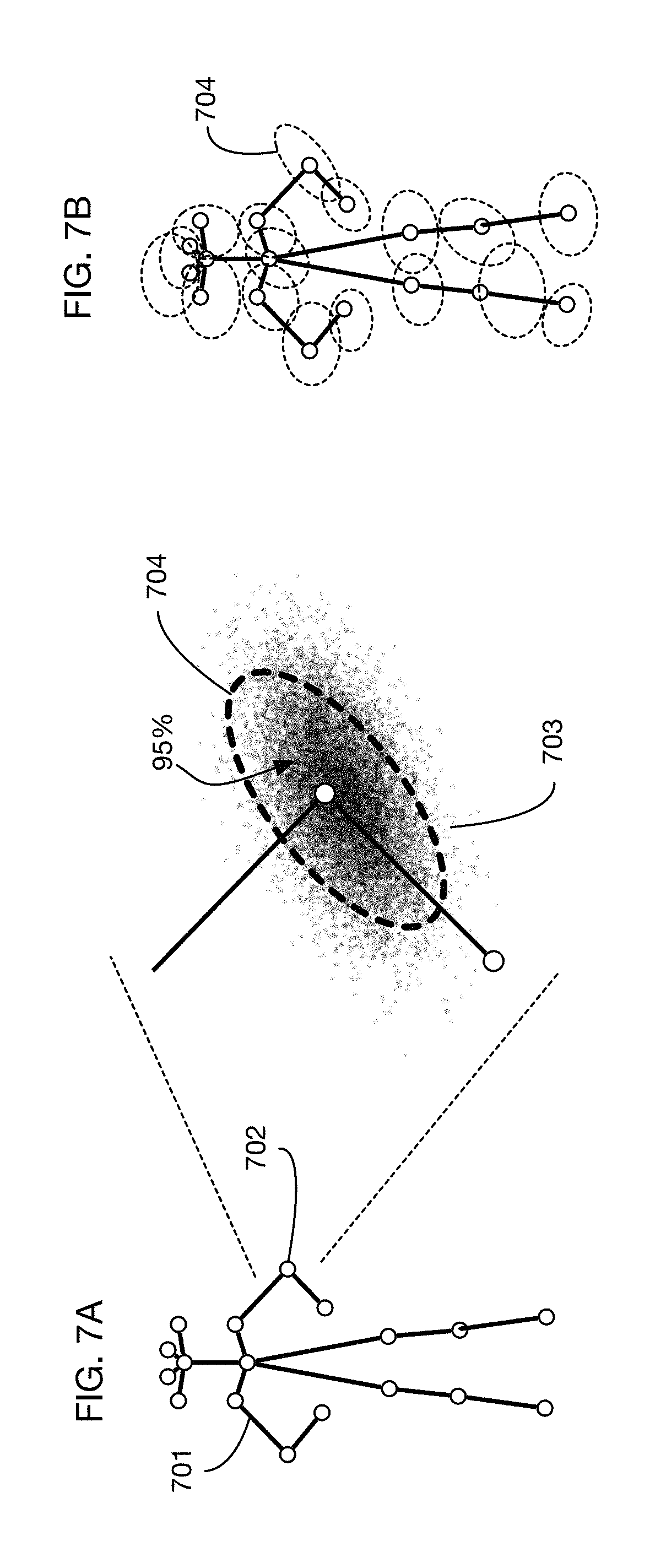
FIGS. 7A and 7B illustrate a different method of determining a field of influence volume around a person by calculating a probability distribution for the location of landmarks on a person's body and setting the volume to include a specified amount of the probability distribution.
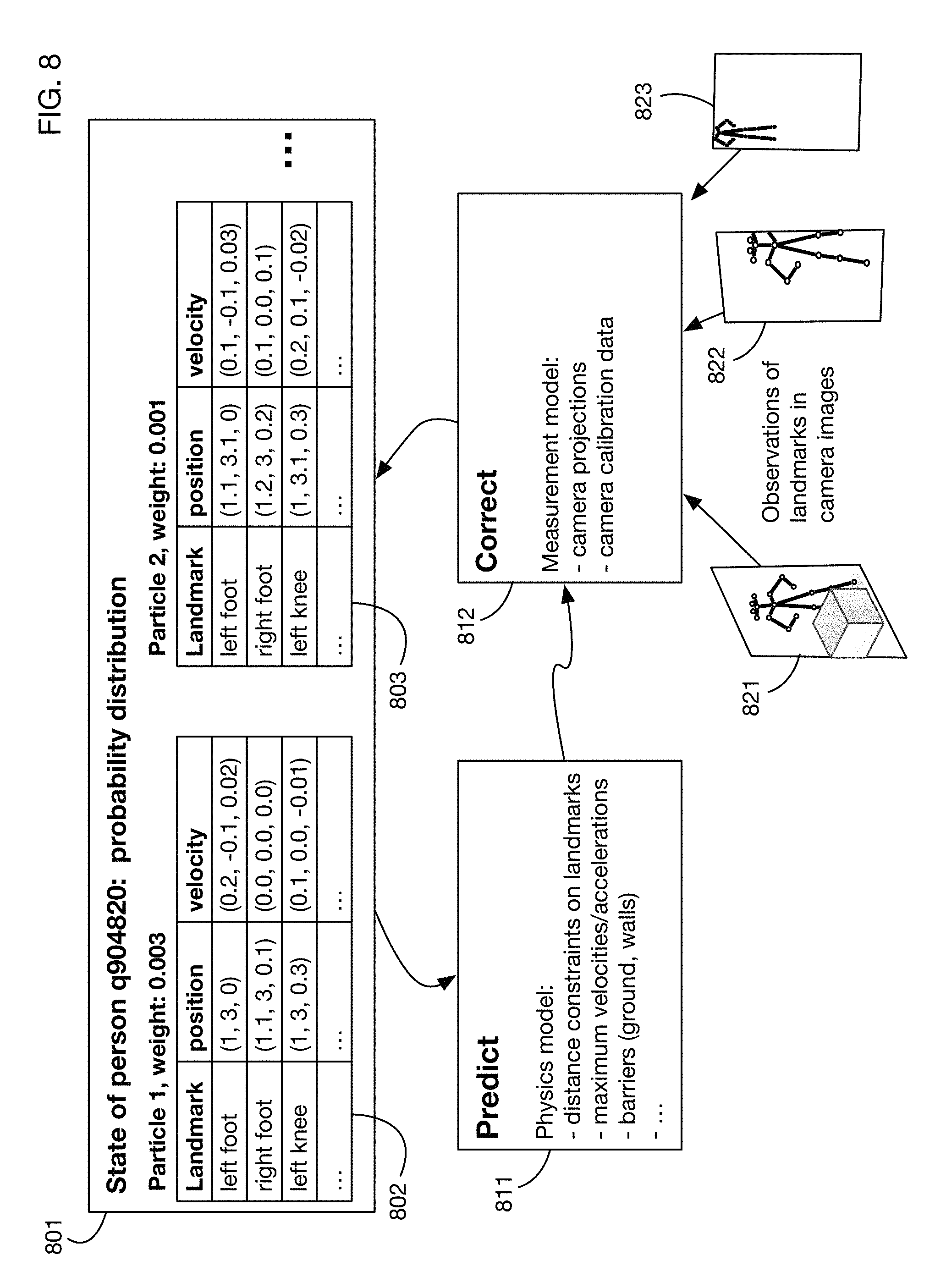
FIG. 8 shows an illustrative method for tracking a person's movements through a store, which uses a particle filter for a probability distribution of the person's state, along with a physics model for motion prediction and a measurement model based on camera image projection observations.
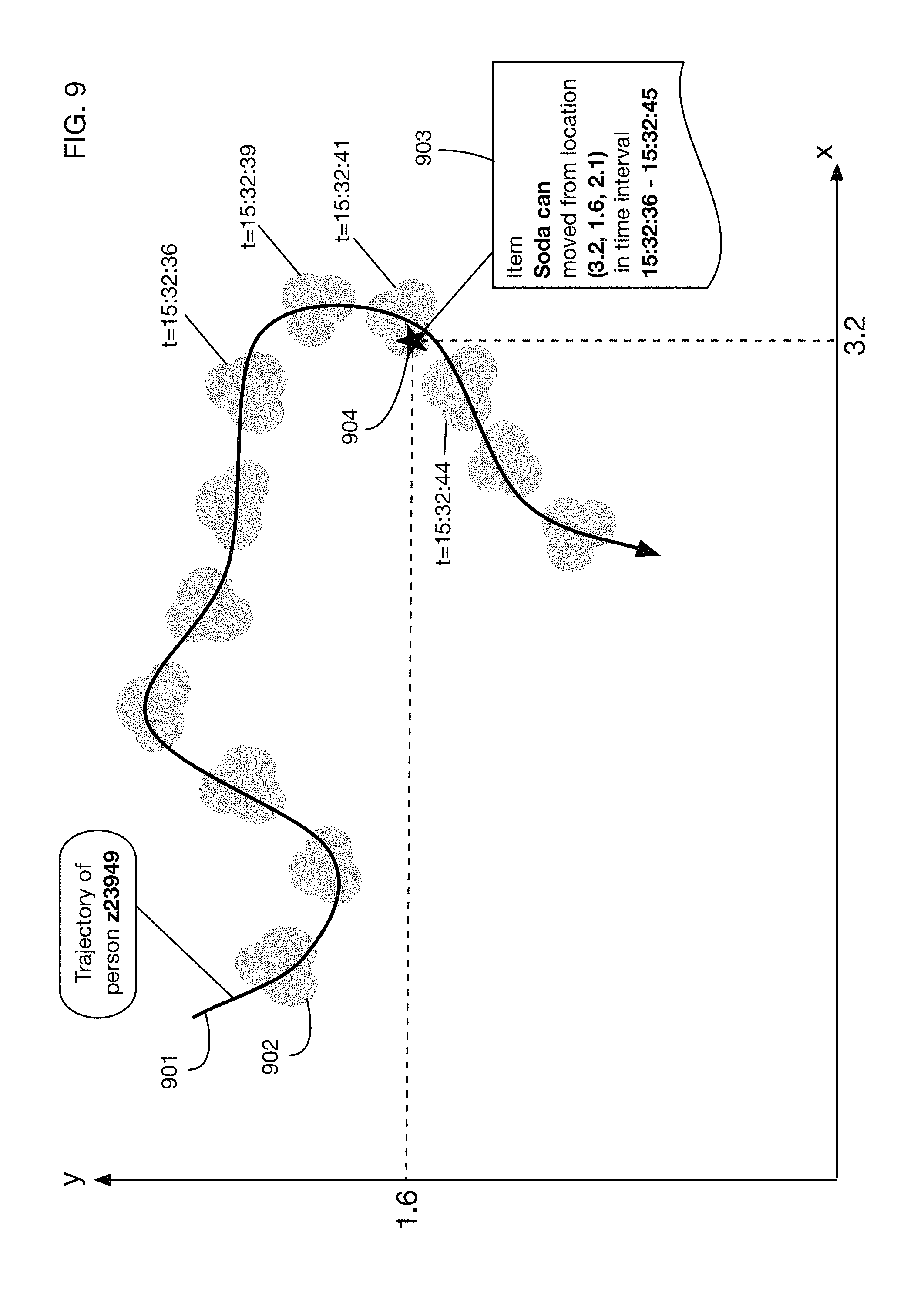
FIG. 9 shows a conceptual model for how one or more embodiments may combine tracking of a person's field of influence with detection of item motion to attribute the motion to a person.
FIG. 10 illustrates an embodiment that attributes item movement to a person by intersecting the person's field of influence volume with an item storage area, such as a shelf and feeding images of the intersected region to a neural network for item detection.
FIG. 11 shows screenshots of an embodiment of the system that tracks two people in a store and detects when one of the tracked people picks up an item.
FIG. 12 shows screenshots of the item storage area of FIG. 11, illustrating how two different images of the item storage area may be input into a neural network for detection of the item that was moved by the person in the store.
FIG. 13 shows the results of the neural network classification in FIG. 12, which tags the people in the store with the items that they move or touch.
FIG. 14 shows a screenshot of an embodiment that identifies a person in a store and builds a 3D field of influence volume around the identified landmarks on the person.
FIG. 15 shows tracking of the person of FIG. 14 as he moves through the store.
FIG. 16 illustrates an embodiment that applies multiple types of camera calibration corrections to images.
FIG. 17 illustrates an embodiment that generates camera calibration data by capturing images of markers placed throughout a store and also corrects for color variations due to hue, saturation or luminance changes across the store and across time.
FIG. 18 illustrates an embodiment that calculates an optimal camera configuration for a store by iteratively optimizing a cost function that measures the number of cameras and the coverage of items by camera fields of view.
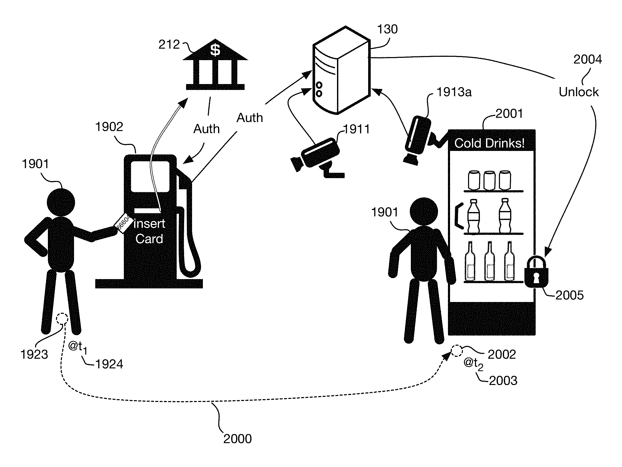
FIG. 19 illustrates an embodiment installed at a gas station that extends an authorization from a card reader at a gas pump to provide automated access to a store where a person may take products and have them charged automatically to the card account.
FIG. 20 shows a variation of the embodiment of FIG. 19, where a locked case containing products is automatically unlocked when the person who paid at a pump is at the case.
FIG. 21 continues the example of FIG. 20, showing that the products taken by the person from the case may be tracked using cameras or other sensors and may be charged to the card account used at the pump.
FIG. 22 continues the example of FIG. 19, illustrating tracking the person once he or she enters the store, analyzing images to determine what products the person has taken and charging the account associated with the card entered at the pump.
FIG. 23 shows a variation of the example of FIG. 22, illustrating tracking that the person picks up and then later puts down an item, so that the item is not charged to the person.
FIG. 24 shows another variation of the example of FIG. 19, where the authorization obtained at the pump may apply to a group of people in a car.
FIGS. 25A, 25B and 25C illustrate an embodiment that queries a user as to whether to extend authorization from the pump to purchases at a store for the user and also for other occupants of the car.
FIGS. 26A through 26F show illustrative camera images from six ceiling-mounted fisheye cameras that may be used for tracking people through a store.
FIGS. 27A, 27B, and 27C show projections of three of the fisheye camera images from FIGS. 26A through 26F onto a horizontal plane one meter above the floor.
FIGS. 28A, 28B, and 28C show binary masks of the foreground objects in FIGS. 27A, 27B, and 27C, respectively, as determined for example by background subtraction or motion filtering. FIG. 28D shows a composite foreground mask that combines all camera image projections to determine the position of people in the store.
FIGS. 29A through 29F show a cylinder generated around one of the persons in the store, as viewed from each of the six fisheye cameras.
FIGS. 30A through 30F show projections of the six fisheye camera views onto the cylinders shown in FIGS. 29A through 29F, respectively. FIG. 30G shows a composite of the six projections of FIGS. 30A through 30F.
FIGS. 31A and 31B show screenshots at two different points in time of an embodiment of a people tracking system using the fisheye cameras described above.
DETAILED DESCRIPTION OF THE INVENTION
A camera-based authorization extension system will now be described. Embodiments may track a person by analyzing camera images and may therefore extend an authorization obtained by this person at one point in time and space to a different point in time or space. Embodiments may also enable an autonomous store system that analyzes camera images to track people and their interactions with items and may also enable camera calibration, optimal camera placement and computer interaction with a point of sale system. The computer interaction may involve a mobile device and a point of sale system for example. In the following exemplary description, numerous specific details are set forth in order to provide a more thorough understanding of embodiments of the invention. It will be apparent, however, to an artisan of ordinary skill that the present invention may be practiced without incorporating all aspects of the specific details described herein. In other instances, specific features, quantities, or measurements well known to those of ordinary skill in the art have not been described in detail so as not to obscure the invention. Readers should note that although examples of the invention are set forth herein, the claims and the full scope of any equivalents, are what define the metes and bounds of the invention.
FIG. 1 shows an embodiment of an automated store. A store may be any location, building, room, area, region, or site in which items of any kind are located, stored, sold, or displayed, or through which people move. For example, without limitation, a store may be a retail store, a warehouse, a museum, a gallery, a mall, a display room, an educational facility, a public area, a lobby, an office, a home, an apartment, a dormitory, or a hospital or other health facility. Items located in the store may be of any type, including but not limited to products that are for sale or rent.
In the illustrative embodiment shown in FIG. 1, store 101 has an item storage area 102, which in this example is a shelf. Item storage areas may be of any type, size, shape and location. They may be of fixed dimensions or they may be of variable size, shape, or location. Item storage areas may include for example, without limitation, shelves, bins, floors, racks, refrigerators, freezers, closets, hangers, carts, containers, boards, hooks, or dispensers. In the example of FIG. 1, items 111, 112, 113 and 114 are located on item storage area 102. Cameras 121 and 122 are located in the store and they are positioned to observe all or portions of the store and the item storage area. Images from the cameras are analyzed to determine the presence and actions of people in the store, such as person 103 and in particular to determine the interactions of these people with items 111-114 in the store. In one or more embodiments, camera images may be the only input required or used to track people and their interactions with items. In one or more embodiments, camera image data may be augmented with other information to track people and their interactions with items. One or more embodiments of the system may utilize images to track people and their interactions with items for example without the use of any identification tags, such as RFID tags or any other non-image based identifiers associated with each item.
FIG. 1 illustrates two cameras, camera 121 and camera 122. In one or more embodiments, any number of cameras may be employed to track people and items. Cameras may be of any type; for example, cameras may be 2D, 3D, or 4D. 3D cameras may be stereo cameras, or they may use other technologies such as rangefinders to obtain depth information. One or more embodiments may use only 2D cameras and may for example determine 3D locations by triangulating views of people and items from multiple 2D cameras. 4D cameras may include any type of camera that can also gather or calculate depth over time, e.g., 3D video cameras.
Cameras 121 and 122 observe the item storage area 102 and the region or regions of store 101 through which people may move. Different cameras may observe different item storage areas or different regions of the store. Cameras may have overlapping views in one or more embodiments. Tracking of a person moving through the store may involve multiple cameras, since in some embodiments no single camera may have a view of the entire store.
Camera images are input into processor 130, which analyzes the images to track people and items in the store. Processor 130 may be any type or types of computer or other device. In one or more embodiments, processor 130 may be a network of multiple processors. When processor 130 is a network of processors, different processors in the network may analyze images from different cameras. Processors in the network may share information and cooperate to analyze images in any desired manner. The processor or processors 130 may be onsite in the store 101, or offsite, or a combination of onsite and offsite processing may be employed. Cameras 121 and 122 may transfer data to the processor over any type or types of network or link, including wired or wireless connections. Processor 130 includes or couples with memory, RAM or disk and may be utilized as a non-transitory data storage computer-readable media that embodiments of the invention may utilize or otherwise include to implement all functionality detailed herein.
Processor or processors 130 may also access or receive a 3D model 131 of the store and may use this 3D model to analyze camera images. The model 131 may for example describe the store dimensions, the locations of item storage areas and items and the location and orientation of the cameras. The model may for example include the floorplan of the store, as well as models of item storage areas such as shelves and displays. This model may for example be derived from a store's planogram, which details the location of all shelving units, their height, as well as which items are placed on them. Planograms are common in retail spaces, so should be available for most stores. Using this planogram, measurements may for example be converted into a 3D model using a 3D CAD package.
If no planogram is available, other techniques may be used to obtain the item storage locations. One illustrative technique is to measure the locations, shapes and sizes of all shelves and displays within the store. These measurements can then be directly converted into a planogram or 3D CAD model. A second illustrative technique involves taking a series of images of all surfaces within the store including the walls, floors and ceilings. Enough images may be taken so that each surface can be seen in at least two images. Images can be either still images or video frames. Using these images, standard 3D reconstruction techniques can be used to reconstruct a complete model of the store in 3D.
In one or more embodiments, a 3D model 131 used for analyzing camera images may describe only a portion of a site, or it may describe only selected features of the site. For example, it may describe only the location and orientation of one or more cameras in the site; this information may be obtained for example from extrinsic calibration of camera parameters. A basic, minimal 3D model may contain only this camera information. In one or more embodiments, geometry describing all or part of a store may be added to the 3D model for certain applications, such as associating the location of people in the store with specific product storage areas. A 3D model may also be used to determine occlusions, which may affect the analysis of camera images. For example, a 3D model may determine that a person is behind a cabinet and is therefore occluded by the cabinet from the viewpoint of a camera; tracking of the person or extraction of the person's appearance may therefore not use images from that camera while the person is occluded.
Cameras 121 and 122 (and other cameras in store 101 if available) may observe item storage areas such as area 102, as well as areas of the store where people enter, leave and circulate. By analyzing camera images over time, the processor 130 may track people as they move through the store. For example, person 103 is observed at time 141 standing near item storage area 102 and at a later time 142 after he has moved away from the item storage area. Using possibly multiple cameras to triangulate the person's position and the 3D store model 131, the processor 130 may detect that person 103 is close enough to item storage area 102 at time 141 to move items on the shelf. By comparing images of storage area 102 at times 141 and 142, the system may detect that item 111 has been moved and may attribute this motion to person 103 since that person was proximal to the item in the time range between 141 and 142. Therefore, the system derives information 150 that the person 103 took item 111 from shelf 102. This information may be used for example for automated checkout, for shoplifting detection, for analytics of shopper behavior or store organization, or for any other purposes. In this illustrative example, person 103 is given an anonymous tag 151 for tracking purposes. This tag may or may not be cross referenced to other information such as for example a shopper's credit card information; in one or more embodiments the tag may be completely anonymous and may be used only to track a person through the store. This enables association of a person with products without require identification of who that particular user is. This is important in locales where people typically wear masks when sick, or other garments which cover the face for example. Also shown is electronic device 119 that generally includes a display that the system may utilize to show the person's list of items, i.e., shopping cart list and with which the person may pay for the items for example.
In one or more embodiments, camera images may be supplemented with other sensor data to determine which products are removed or the quantity of a product that is taken or dispensed. For example, a product shelf such as shelf 102 may have weight sensors or motion sensors that assist in detecting that products are taken, moved, or replaced on the shelf. One or more embodiments may receive and process data indicating the quantity of a product that is taken or dispensed, and may attribute this quantity to a person, for example to charge this quantity to the person's account. For example, a dispenser of a liquid such as a beverage may have a flow sensor that measures the amount of liquid dispensed; data from the flow sensor may be transmitted to the system to attribute this amount to a person proximal to the dispenser at the time of dispensing. A person may also press a button or provide other input to determine what products or quantities should be dispensed; data from the button or other input device may be transmitted to the system to determine what items and quantities to attribute to a person.
FIG. 2 continues the example of FIG. 1 to show an automated checkout. In one or more embodiments, processor 130 or another linked system may detect that a person 103 is leaving a store or is entering an automated checkout area. For example, a camera or cameras such as camera 202 may track person 103 as he or she exits the store. If the system 130 has determined that person 103 has an item, such as item 111 and if the system is configured to support automated checkout, then it may transmit a message 203 or otherwise interface with a checkout system such as a point of sale system 210. This message may for example trigger an automated charge 211 for the item (or items) believed to be taken by person 103, which may for example be sent to financial institution or system 212. In one or more embodiments a message 213 may also be displayed or otherwise transmitted to person 103 confirming the charge, e.g., on the person's electronic device 119 shown in FIG. 1. The message 213 may for example be displayed on a display visible to the person exiting or in the checkout area, or it may be transmitted for example via a text message or email to the person, for example to a computer or mobile device 119 (see FIG. 1) associated with the user. In one or more embodiments the message 213 may be translated to a spoken message. The fully automated charge 211 may for example require that the identity of person 103 be associated with financial information, such as a credit card for example. One or more embodiments may support other forms of checkout that may for example not require a human cashier but may ask person 103 to provide a form of payment upon checkout or exit. A potential benefit of an automated checkout system such as that shown in FIG. 2 is that the labor required for the store may be eliminated or greatly reduced. In one or more embodiments, the list of items that the store believes the user has taken may be sent to a mobile device associated with the user for the user's review or approval.
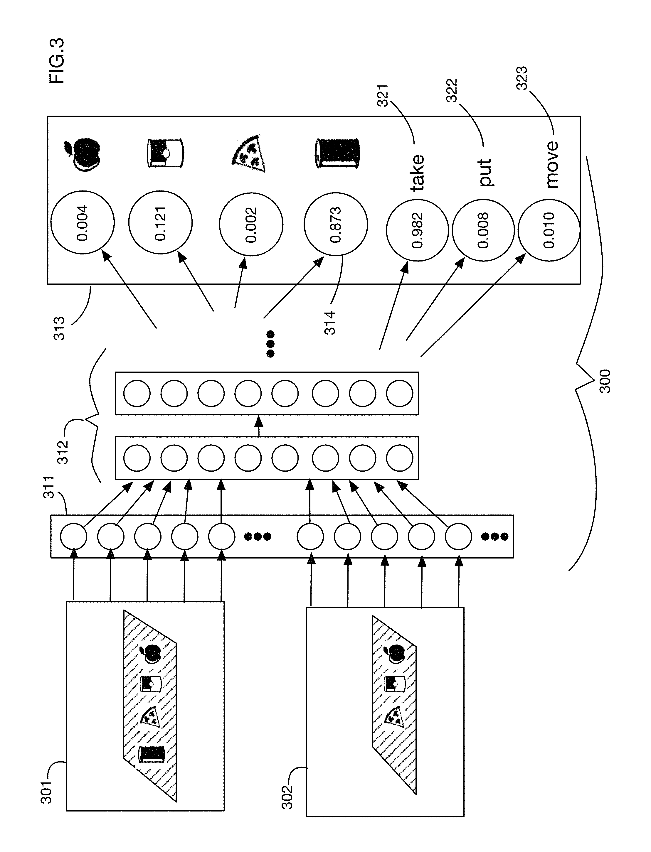
As illustrated in FIG. 1, in one or more embodiments analysis of a sequence of two or more camera images may be used to determine that a person in a store has interacted with an item in an item storage area. FIG. 3 shows an illustrative embodiment that uses an artificial neural network 300 to identify an item that has been moved from a pair of images, e.g., an image 301 obtained prior to the move of the item and an image 302 obtained after the move of the item. One or more embodiments may analyze any number of images, including but not limited to two images. These images 301 and 302 may be fed as inputs into input layer 311 of a neural network 300, for example. (Each color channel of each pixel of each image may for example be set as the value of an input neuron in input layer 311 of the neural network.) The neural network 300 may then have any number of additional layers 312, connected and organized in any desired fashion. For example, without limitation, the neural network may employ any number of fully connected layers, convolutional layers, recurrent layers, or any other type of neurons or connections. In one or more embodiments the neural network 300 may be a Siamese neural network organized to compare the two images 301 and 302. In one or more embodiments, neural network 300 may be a generative adversarial network, or any other type of network that performs input-output mapping.
The output layer 313 of the neural network 300 may for example contain probabilities that each item was moved. One or more embodiments may select the item with the highest probability, in this case output neuron 313 and associate movement of this item with the person near the item storage area at the time of the movement of the item. In one or more embodiments there may be an output indicating no item was moved.
The neural network 300 of FIG. 3 also has outputs classifying the type of movement of the item. In this illustrative example there are three types of motions: a take action 321, which indicates for example that the item appeared in image 301 but not in image 302; a put action 322, which indicates for example that the item appears in image 302 but not in image 301; and a move action 323, which indicates for example that the item appears in both images but in a different location. These actions are illustrative; one or more embodiments may classify movement or rearrangement of items into any desired classes and may for example assign a probability to each class. In one or more embodiments, separate neural networks may be used to determine the item probabilities and the action class probabilities. In the example of FIG. 3, the take class 321 has the highest calculated probability, indicating that the system most likely detects that the person near the image storage area has taken the item away from the storage area.
The neural network analysis as indicated in FIG. 3 to determine which item or items have been moved and the types of movement actions performed is an illustrative technique for image analysis that may be used in one or more embodiments. One or more embodiments may use any desired technique or algorithm to analyze images to determine items that have moved and the actions that have been performed. For example, one or more embodiments may perform simple frame differences on images 301 and 302 to identify movement of items. One or more embodiments may preprocess images 301 and 302 in any desired manner prior to feeding them to a neural network or other analysis system. For example, without limitation, preprocessing may align images, remove shadows, equalize lighting, correct color differences, or perform any other modifications. Images may be processed with any classical image processing algorithms such as color space transformation, edge detection, smoothing or sharpening, application of morphological operators, or convolution with filters.
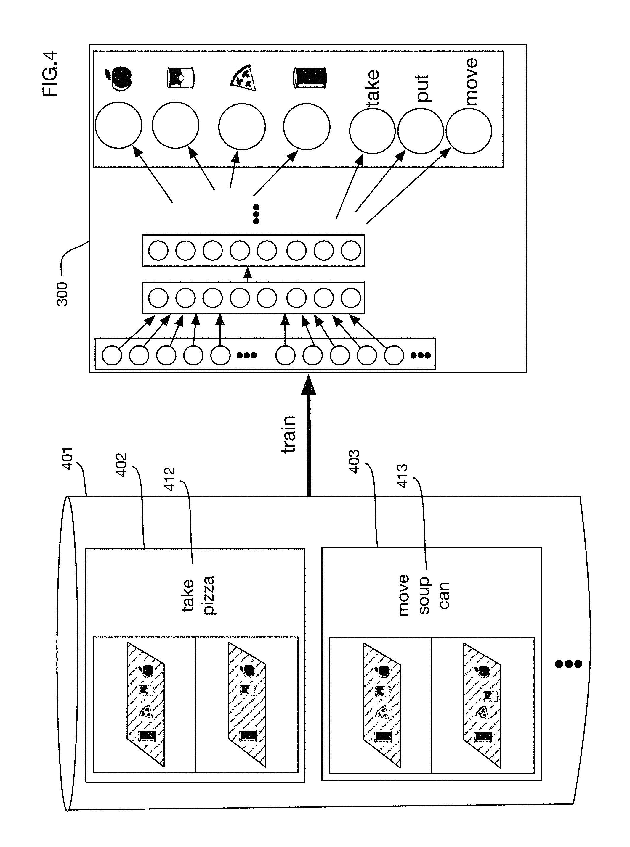
One or more embodiments may use machine learning techniques to derive classification algorithms such as the neural network algorithm applied in FIG. 3. FIG. 4 shows an illustrative process for learning the weights of the neural network 300 of FIG. 3. A training set 401 of examples may be collected or generated and used to train network 300. Training examples such as examples 402 and 403 may for example include before and after images of an item storage area and output labels 412 and 413 that indicate the item moved and the type of action applied to the item. These examples may be constructed manually, or in one or more embodiments there may be an automated training process that captures images and then uses checkout data that associates items with persons to build training examples. FIG. 4A shows an example of augmenting the training data with examples that correct misclassifications by the system. In this example, the store checkout is not fully automated; instead, a cashier 451 assists the customer with checkout. The system 130 has analyzed camera images and has sent message 452 to the cashier's point of sale system 453. The message contains the system's determination of the item that the customer has removed from the item storage area 102. However, in this case the system has made an error. Cashier 451 notices the error and enters a correction into the point of sale system with the correct item. The corrected item and the images from the camera may then be transmitted as a new training example 454 that may be used to retrain neural network 300. In time, the cashier may be eliminated when the error rate converges to an acceptable predefined level. In one or more embodiments, the user may show the erroneous item to the neural network via a camera and train the system without cashier 451. In other embodiments, cashier 451 may be remote and accessed via any communication method including video or image and audio-based systems.
In one or more embodiments, people in the store may be tracked as they move through the store. Since multiple people may be moving in the store simultaneously, it may be beneficial to distinguish between persons using image analysis, so that people can be correctly tracked. FIG. 5 shows an illustrative method that may be used to distinguish among different persons. As a new person 501 enters a store or enters a specified area or areas of the store at time 510, images of the person from cameras such as cameras 511, 512 and 513 may be analyzed to determine certain characteristics 531 of the person's appearance that can be used to distinguish that person from other people in the store. These distinguishing characteristics may include for example, without limitation: the size or shape of certain body parts; the color, shape, style, or size of the person's hair; distances between selected landmarks on the person's body or clothing; the color, texture, materials, style, size, or type of the person's clothing, jewelry, accessories, or possessions; the type of gait the person uses when walking or moving; the speed or motion the person makes with any part of their body such as hands, arms, legs, or head; and gestures the person makes. One or more embodiments may use high resolution camera images to observe biometric information such as a person's fingerprints or handprints, retina, or other features.
In the example shown in FIG. 5, at time 520 a person 502 enters the store and is detected to be a new person. New distinguishing characteristics 532 are measured and observed for this person. The original person 501 has been tracked and is now observed to be at a new location 533. The observations of the person at location 533 are matched to the distinguishing characteristics 531 to identify the person as person 501.
In the example of FIG. 5, although distinguishing characteristics are identified for persons 501 and 502, the identities of these individuals remain anonymous. Tags 541 and 542 are assigned to these individuals for internal tracking purposes, but the persons' actual identities are not known. This anonymous tracking may be beneficial in environments where individuals do not want their identities to be known to the autonomous store system. Moreover, sensitive identifying information, such as for example images of a person's face, need not be used for tracking; one or more embodiments may track people based on other less sensitive information such as the distinguishing characteristics 531 and 532. As previously described, in some areas, people wear masks when sick or otherwise wear face garments, making identification based on a user's face impossible.
The distinguishing characteristics 531 and 532 of persons 501 and 502 may or may not be saved over time to recognize return visitors to the store. In some situations, a store may want to track return visitors. For example, shopper behavior may be tracked over multiple visits if the distinguishing characteristics are saved and retrieved for each visitor. Saving this information may also be useful to identify shoplifters who have previously stolen from the store, so that the store personnel or authorities can be alerted when a shoplifter or potential shoplifter returns to the store. In other situations, a store may want to delete distinguishing information when a shopper leaves the store, for example if there are potential concern that the store may be collecting information that the shopper's do not want saved over time.
In one or more embodiments, the system may calculate a 3D field of influence volume around a person as it tracks the person's movement through the store. This 3D field of influence volume may for example indicate a region in which the person can potentially touch or move items. A detection of an item that has moved may for example be associated with a person being tracked only if the 3D field of influence volume for that person is near the item at the time of the item's movement.
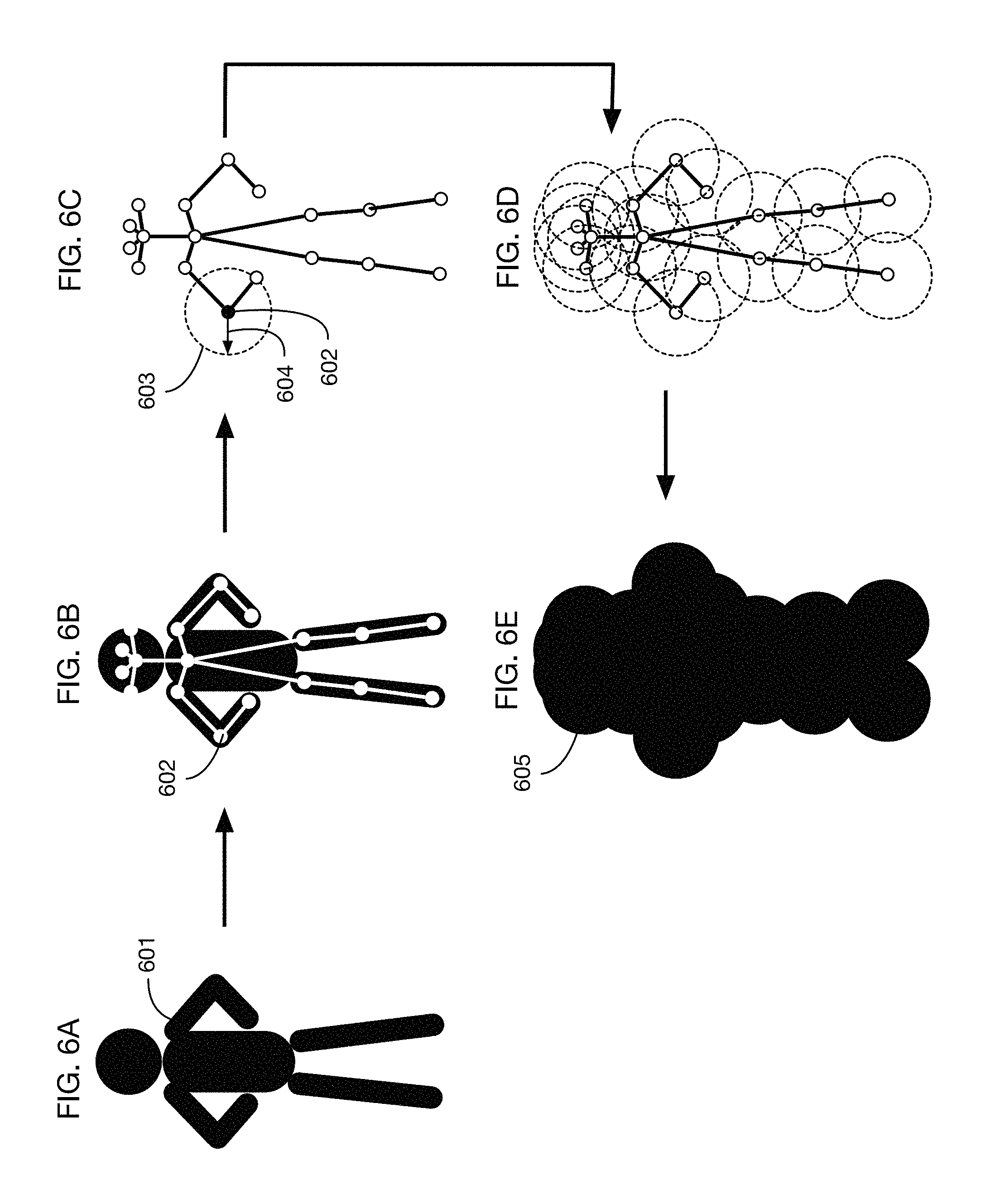
Various methods may be used to calculate a 3D field of influence volume around a person. FIGS. 6A through 6E illustrate a method that may be used in one or more embodiments. (These figures illustrate the construction of a field of influence volume using 2D figures, for ease of illustration, but the method may be applied in three dimensions to build a 3D volume around the person.) Based on an image or images 601 of a person, image analysis may be used to identify landmarks on the person's body. For example, landmark 602 may be the left elbow of the person. FIG. 6B illustrates an analysis process that identifies 18 different landmarks on the person's body. One or more embodiments may identify any number of landmarks on a body, at any desired level of detail. Landmarks may be connected in a skeleton in order to track the movement of the person's joints. Once landmark locations are identified in the 3D space associated with the store, one method for constructing a 3D field of influence volume is to calculate a sphere around each landmark with a radius of a specified threshold distance. For example, one or more embodiments may use a threshold distance of 25 cm offset from each landmark. FIG. 6C shows sphere 603 with radius 604 around landmark 602. These spheres may be constructed around each landmark, as illustrated in FIG. 6D. The 3D field of influence volume may then be calculated as the union of these spheres around the landmarks, as illustrated with 3D field of influence volume 605 in FIG. 6E.
Another method of calculating a 3D field of influence volume around a person is to calculate a probability distribution for the location of each landmark and to define the 3D field of influence volume around a landmark as a region in space that contains a specified threshold amount of probability from this probability distribution. This method is illustrated in FIGS. 7A and 7B. Images of a person are used to calculate landmark positions 701, as described with respect to FIG. 6B. As the person is tracked through the store, uncertainty in the tracking process results in a probability distribution for the 3D location of each landmark. This probability distribution may be calculated and tracked using various methods, including a particle filter as described below with respect to FIG. 8. For example, for the right elbow landmark 702 in FIG. 7A, a probability density 703 may be calculated for the position of the landmark. (This density is shown in FIG. 7A as a 2D figure for ease of illustration, but in tracking it will generally be a 3D spatial probability distribution.) A volume may be determined that contains a specified threshold probability amount of this probability density for each landmark. For example, the volume enclosed by surface may enclose 95% (or any other desired amount) of the probability distribution 703. The 3D field of influence volume around a person may then be calculated as the union of these volumes 704 around each landmark, as illustrated in FIG. 7B. The shape and size of the volumes around each landmark may differ, reflecting differences in the uncertainties for tracking the different landmarks.
FIG. 8 illustrates a technique that may be used in one or more embodiments to track a person over time as he or she moves through a store. The state of a person at any point in time may for example be represented as a probability distribution of certain state variables such as the position and velocity (in three dimensions) of specific landmarks on the person's body. One approach to representing this probability distribution is to use a particle filter, where a set of particles is propagated over time to represent weighted samples from the distribution. In the example of FIG. 8, two particles 802 and 803 are shown for illustration; in practice the probability distribution at any point in time may be represented by hundreds or thousands of particles. To propagate state 801 to a subsequent point in time, one or more embodiments may employ an iterative prediction/correction loop. State 801 is first propagated through a prediction step 811, which may for example use a physics model to estimate for each particle what the next state of the particle is. The physics model may include for example, without limitation, constraints on the relative location of landmarks (for example, a constraint that the distance between the left foot and the left knee is fixed), maximum velocities or accelerations at which body parts can move and constraints from barriers in the store, such as floors, walls, fixtures, or other persons. These physics model components are illustrative; one or more embodiments may use any type of physics model or other model to propagate tracking state from one time period to another. The predict step 811 may also reflect uncertainties in movements, so that the spread of the probability distribution may increase over time in each predict step, for example. The particles after the prediction step 811 are then propagated through a correction step 812, which incorporates information obtained from measurements in camera images, as well as other information if available. The correction step uses camera images such as images 821, 822, 823 and information on the camera projections of each camera as well as other camera calibration data if available. As illustrated in images 821, 822 and 823, camera images may provide only partial information due to occlusion of the person or to images that capture only a portion of the person's body. The information that is available is used to correct the predictions, which may for example reduce the uncertainty in the probability distribution of the person's state. This prediction/correction loop may be repeated at any desired interval to track the person through the store.
By tracking a person as he or she moves through the store, one or more embodiments of the system may generate a 3D trajectory of the person through the store. This 3D trajectory may be combined with information on movement of items in item storage areas to associate people with the items they interact with. If the person's trajectory is proximal to the item at a time when the item is moved, then the movement of the item may be attributed to that person, for example. FIG. 9 illustrates this process. For ease of illustration, the person's trajectory and the item position are shown in two dimensions; one or more embodiments may perform a similar analysis in three dimensions using the 3D model of the store, for example. A trajectory 901 of a person is tracked over time, using a tracking process such as the one illustrated in FIG. 8, for example. For each person, a 3D field of influence volume 902 may be calculated at each point in time, based for example on the location or probability distribution of landmarks on the person's body. (Again, for ease of illustration the field of influence volume shown in FIG. 9 is in the two dimension, although in implementation this volume may be three dimensional.) The system calculates the trajectory of the 3D influence volume through the store. Using camera image analysis such as the analysis illustrated in FIG. 3, motion 903 of an item is detected at a location 904. Since there may be multiple people tracked in a store, the motion may be attributed to the person whose field of influence volume was at or near this location at the time of motion. Trajectory 901 shows that the field of influence volume of this tracked person intersected the location of the moved item during a time interval proximal in time to this motion; hence the item movement may be attributed to this person.
In one or more embodiments the system may optimize the analysis described above with respect to FIG. 9 by looking for item movements only in item storage areas that intersect a person's 3D field of influence volume. FIG. 10 illustrates this process. At a point in time 141 or over a time interval, the tracked 3D field of influence volume 1001 of person 103 is calculated to be near item storage area 102. The system therefore calculates an intersection 1011 of the item storage area 102 and the 3D field of influence volume 1001 around person 1032 and locates camera images that contain views of this region, such as image 1011. At a subsequent time 142, for example when person 103 is determined to have moved away from item storage area 102, an image 1012 (or multiple such images) is obtained of the same intersected region. These two images are then fed as inputs to neural network 300, which may for example detect whether any item was moved, which item was moved (if any) and the type of action that was performed. The detected item motion is attributed to person 103 because this is the person whose field of influence volume intersected the item storage area at the time of motion. By applying the classification analysis of neural network 300 only to images that represent intersections of person's field of influence volume with item storage areas, processing resources may be used efficiently and focused only on item movement that may be attributed to a tracked person.
FIGS. 11 through 15 show screenshots of an embodiment of the system in operation in a typical store environment. FIG. 11 shows three camera images 1101, 1102 and 1103 taken of shoppers moving through the store. In image 1101, two shoppers 1111 and 1112 have been identified and tracked. Image 1101 shows landmarks identified on each shopper that are used for tracking and for generating a 3D field of influence volume around each shopper. Distances between landmarks and other features such as clothing may be used to distinguish between shoppers 1111 and 1112 and to track them individually as they move through the store. Images 1102 and 1103 show views of shopper 1111 as he approaches item storage area 1113 and picks up an item 114 from the item storage area. Images 1121 and 1123 show close up views from images 1101 and 1103, respectively, of item storage area 1113 before and after shopper 1111 picks up the item.
FIG. 12 continues the example shown in FIG. 11 to show how images 1121 and 1123 of the item storage area are fed as inputs into a neural network 1201 to determine what item, if any, has been moved by shopper 1111. The network assigns the highest probability to item 1202. FIG. 13 shows how the system attributes motion of this item 1202 to shopper 1111 and assigns an action 1301 to indicate that the shopper picked up the item. This action 1301 may also be detected by neural network 1201, or by a similar neural network. Similarly, the system has detected that item 1303 has been moved by shopper 1112 and it assigns action 1302 to this item movement.
FIG. 13 also illustrates that the system has detected a "look at" action 1304 by shopper 1111 with respect to item 1202 that the shopper picked up. In one or more embodiments, the system may detect that a person is looking at an item by tracking the eyes of the person (as landmarks, for example) and by projecting a field of view from the eyes towards items. If an item is within the field of view of the eyes, then the person may be identified as looking at the item. For example, in FIG. 13 the field of view projected from the eyes landmarks of shopper 1111 is region 1305 and the system may recognize that item 1202 is within this region. One or more embodiments may detect that a person is looking at an item whether or not that item is moved by the person; for example, a person may look at an item in an item storage area while browsing and may subsequently choose not to touch the item.
In one or more embodiments, other head landmarks instead of or in addition to the eyes may be used to compute head orientation relative to the store reference frame to determine what a person is looking at. Head orientation may be computed for example via 3D triangulated head landmarks. One or more embodiments may estimate head orientation from 2D landmarks using for example a neural network that is trained to estimate gaze in 3D from 2D landmarks.
FIG. 14 shows a screenshot 1400 of the system creating a 3D field of influence volume around a shopper. The surface of the 3D field of influence volume 1401 is represented in this image overlay as a set of dots on the surface. The surface 1401 may be generated as an offset from landmarks identified on the person, such as landmark 1402 for the person's right foot for example. Screenshot 1410 shows the location of the landmarks associated with the person in the 3D model of the store.
FIG. 15 continues the example of FIG. 14 to show tracking of the person and his 3D field of influence volume as he moves through the store in camera images 1501 and 1502 and generation of a trajectory of the person's landmarks in the 3D model of the store in screenshots 1511 and 1512.
In one or more embodiments, the system may use camera calibration data to transform images obtained from cameras in the store. Calibration data may include for example, without limitation, intrinsic camera parameters, extrinsic camera parameters, temporal calibration data to align camera image feeds to a common time scale and color calibration data to align camera images to a common color scale. FIG. 16 illustrates the process of using camera calibration data to transform images. A sequence of raw images 1601 is obtained from camera 121 in the store. A correction 1602 for intrinsic camera parameters is applied to these raw images, resulting in corrected sequence 1603. Intrinsic camera parameters may include for example the focal length of the camera, the shape and orientation of the imaging sensor, or lens distortion characteristics. Corrected images 1603 are then transformed in step 1604 to map the images to the 3D store model, using extrinsic camera parameters that describe the camera projection transformation based on the location and orientation of the camera in the store. The resulting transformed images 1605 are projections aligned with respect to a coordinate system 1606 of the store. These transformed images 1605 may then be shifted in time to account for possible time offsets among different cameras in the store. This shifting 1607 synchronizes the frames from the different cameras in the store to a common time scale. In the last transformation 1609, the color of pixels in the time corrected frames 1608 may be modified to map colors to a common color space across the cameras in the store, resulting in final calibrated frames 1610. Colors may vary across cameras because of differences in camera hardware or firmware, or because of lighting conditions that vary across the store; color correction 1609 ensures that all cameras view the same object as having the same color, regardless of where the object is in the store. This mapping to a common color space may for example facilitate the tracking of a person or an item selected by a person as the person or item moves from the field of view of one camera to another camera, since tracking may rely in part on the color of the person or item.
The camera calibration data illustrated in FIG. 16 may be obtained from any desired source. One or more embodiments may also include systems, processes, or methods to generate any or all of this camera calibration data. FIG. 17 illustrates an embodiment that generates camera calibration data 1701, including for example any or all of intrinsic camera parameters, extrinsic camera parameter, time offsets for temporal synchronization and color mapping from each camera to a common color space. Store 1702 contains for this example three cameras, 1703, 1704 and 1705. Images from these cameras are captured during calibration procedures and are analyzed by camera calibration system 1710. This system may be the same as or different from the system or systems used to track persons and items during store operations. Calibration system 1710 may include or communicate with one or more processors. For calibration of intrinsic camera parameters, standard camera calibration grids for example may be placed in the store 1702. For calibration of extrinsic camera parameters, markers of a known size and shape may for example be placed in known locations in the store, so that the position and orientation of cameras 1703, 1704 and 1705 may be derived from the images of the markers. Alternatively, an iterative procedure may be used that simultaneously solves for marker positions and for camera positions and orientations.
A temporal calibration procedure that may be used in one or more embodiments is to place a source of light 1705 in the store and to pulse a flash of light from the source 1705. The time that each camera observes the flash may be used to derive the time offset of each camera from a common time scale. The light flashed from source 1705 may be visible, infrared, or of any desired wavelength or wavelengths. If all cameras cannot observe a single source, then either multiple synchronized light sources may be used, or cameras may be iteratively synchronized in overlapping groups to a common time scale.
A color calibration procedure that may be used in one or more embodiments is to place one or more markers of known colors into the store and to generate color mappings from each camera into a known color space based on the images of these markers observed by the cameras. For example, color markers 1721, 1722 and 1723 may be placed in the store; each marker may for example have a grid of standard color squares. In one or more embodiments the color markers may also be used for calibration of extrinsic parameters; for example, they may be placed in known locations as shown in FIG. 17. In one or more embodiments items in the store may be used for color calibration if for example they are of a known color.
Based on the observed colors of the markers 1721, 1722 and 1723 in a specific camera, a mapping may be derived to transform the observed colors of the camera to a standard color space. This mapping may be linear or nonlinear. The mapping may be derived for example using a regression or using any desired functional approximation methodology.
The observed color of any object in the store, even in a camera that is color calibrated to a standard color space, depends on the lighting at the location of the object in the store. For example, in store 1702 an object near light 1731 or near window 1732 may appear brighter than objects at other locations in the store. To correct for the effect of lighting variations on color, one or more embodiments may create and/or use a map of the luminance or other lighting characteristics across the store. This luminance map may be generated based on observations of lighting intensity from cameras or from light sensors, on models of the store lighting, or on a combination thereof. In the example of FIG. 17, illustrative luminance map 1741 may be generated during or prior to camera calibration and it may be used in mapping camera colors to a standard color space. Since lighting conditions may change at different times of day, one or more embodiments may generate different luminance maps for different times or time periods. For example, luminance map 1742 may be used for nighttime operation, when light from window 1732 is diminished but store light 1731 continues to operate.
In one or more embodiments, filters may be added to light sources or to cameras, or both, to improve tracking and detection. For example, point lights may cause glare in camera images from shiny products. Polarizing filters on light may reduce this glare, since polarized light generates less glare. Polarizing filters on light sources may be combined with polarizers on cameras to further reduce glare.
In addition to or instead of using different luminance maps at different times to account for changes in lighting conditions, one or more embodiments may recalibrate cameras as needed to account for the effects of changing lighting conditions on camera color maps. For example, a timer 1751 may trigger camera calibration procedure 1710, so that for example camera colors are recalibrated at different times of day. Alternatively, or in addition, light sensors 1752 located in store 1702 may trigger camera calibration procedure 1710 when the sensor or sensors detect that lighting conditions have changed or may have changed. Embodiments of the system may also sub-map calibration to specific areas of images, for example if window 1732 allows sunlight in to a portion of the store. In other words, the calibration data may also be based on area and time to provide even more accurate results.
In one or more embodiments, camera placement optimization may be utilized in the system. For example, in a 2D camera scenario, one method that can be utilized is to assign a cost function to camera positions to optimize the placement and number of cameras for a particular store. In one embodiment, assigning a penalty of 1000 to any item that is only found in one image from the cameras results in a large penalty for any item only viewable by one camera. Assigning a penalty of 1 to the number of cameras results in a slight penalty for additional cameras required for the store. By penalizing camera placements that do not produce at least two images or a stereoscopic image of each item, then the number of items for which 3D locations cannot be obtained is heavily penalized so that the final camera placement is under a predefined cost. One or more embodiments thus converge on a set of camera placements where two different viewpoints to all items is eliminated given enough cameras. By placing a cost function on the number of cameras, the iterative solution according to this embodiment thus is employed to find at least one solution with a minimal number of cameras for the store. As shown in the upper row of FIG. 18, the items on the left side of the store only have one camera, the middle camera pointing towards them. Thus, those items in the upper right table incur a penalty of 1000 each. Since there are 3 cameras in this iteration, the total cost is 2003. In the next iteration, a camera is added as shown in the middle row of the figure. Since all items can now be seen by at least two cameras, the cost drops to zero for items, while another camera has been added so that the total cost is 4. In the bottom row as shown for this iteration, a camera is removed, for example by determining that certain items are viewed by more than 2 cameras as shown in the middle column of the middle row table, showing 3 views for 4 items. After removing the far-left camera in the bottom row store, the cost decreases by 1, thus the total cost is 3. Any number of camera positions, orientations and types may be utilized in embodiments of the system. One or more embodiments of the system may optimize the number of cameras by using existing security cameras in a store and by moving those cameras if needed or augmenting the number of cameras for the store to leverage existing video infrastructure in a store, for example in accordance with the camera calibration previously described. Any other method of placing and orienting cameras, for example equal spacing and a predefined angle to set an initial scenario may be utilized.
In one or more embodiments, one or more of the techniques described above to track people and their interactions with an environment may be applied to extend an authorization obtained by a person at one point in time and space to another point in time or space. For example, an authorization may be obtained by a person at an entry point to an area or a check point in the area and at an initial point in time. The authorization may authorize the person to perform one or more actions, such as for example to enter a secure environment such as a locked building, or to charge purchases to an account associated with the person. The system may then track this person to a second location at a subsequent point in time and may associate the previously obtained authorization with that person at the second location and at the subsequent point in time. This extension of an authorization across time and space may simplify the interaction of the person with the environment. For example, a person may need to or choose to present a credential (such as a payment card) at the entry point to obtain an authorization to perform purchases; because the system may track that person afterwards, this credential may not need to be presented again to use the previously obtained authorization. This extension of authorization may for example be useful in automated stores in conjunction with the techniques described above to determine which items a person interacts with or takes within the store; a person might for example present a card at a store entrance or at a payment kiosk or card reader associated with the store and then simply take items as desired and be charged for them automatically upon leaving the store, without performing any explicit checkout.
FIG. 19 shows an illustrative embodiment that enables authorization extension using tracking via analysis of camera images. This figure and several subsequent figures illustrate one or more aspects of authorization extension using a gas station example. This example is illustrative; one or more embodiments may enable authorization extension at any type of site or area. For example, without limitation, authorization extension may be applied to or integrated into all of or any portion of a building, a multi-building complex, a store, a restaurant, a hotel, a school, a campus, a mall, a parking lot, an indoor or outdoor market, a residential building or complex, a room, a stadium, a field, an arena, a recreational area, a park, a playground, a museum, or a gallery. It may be applied or integrated into any environment where an authorization obtained at one time and place may be extended to a different time or different place. It may be applied to extend any type of authorization.
In the example shown in FIG. 19, a person 1901 arrives at a gas station and goes to gas pump 1902. To obtain gas (or potentially to authorize other actions without obtaining gas), person 1901 presents a credential 1904, such as for example a credit or debit card, into credential reader 1905 on or near the pump 1902. The credential reader 1905 transmits a message 1906 to a bank or clearinghouse 212 to obtain an authorization 1907, which allows user 1901 to pump gas from pump 1902.
In one or more embodiments, a person may present any type of credential to any type of credential reader to obtain an authorization. For example, without limitation, a credential may be a credit card, a debit card, a bank card, an RFID tag, a mobile payment device, a mobile wallet device, a mobile phone, a smart phone, a smart watch, smart glasses or goggles, a key fob, an identity card, a driver's license, a passport, a password, a PIN, a code, a phone number, or a biometric identifier. A credential may be integrated into or attached to any device carried by a person, such as a mobile phone, smart phone, smart watch, smart glasses, key fob, smart goggles, tablet, or computer. A credential may be worn by a person or integrated into an item of clothing or an accessory worn by a person. A credential may be passive or active. A credential may or may not be linked to a payment mechanism or an account. In one or more embodiments a credential may be a password, PIN, code, phone number, or other data typed or spoken or otherwise entered by a person into a credential reader. A credential reader may be any device or combination of devices that can read or accept a presented credential. A credential reader may or may not be linked to a remote authorization system like bank 212. In one or more embodiments a credential reader may have local information to authorize a user based on a presented credential without communicating with other systems. A credential reader may read, recognize, accept, authenticate, or otherwise process a credential using any type of technology. For example, without limitation, a credential reader may have a magnetic stripe reader, a chip card reader, an RFID tag reader, an optical reader or scanner, a biometric reader such as a fingerprint scanner, a near field communication receiver, a Bluetooth receiver, a Wi-Fi receiver, a keyboard or touchscreen for typed input, or a microphone for audio input. A credential reader may receive signals, transmit signals, or both.
In one or more embodiments, an authorization obtained by a person may be associated with any action or actions the person is authorized to perform. These actions may include, but are not limited to, financial transactions such as purchases. Actions that may be authorized may include for example, without limitation, entry to or exit from a building, room, or area; purchasing or renting of items, products, or services; use of items, products, or services; or access to controlled information or materials.
In one or more embodiments, a credential reader need not be integrated into a gas pump or into any other device. It may be standalone, attached to or integrated into any device, or distributed across an area. A credential reader may be located in any location in an area, including for example, without limitation, at an entrance, exit, check-in point, checkpoint, control point, gate, door, or other barrier. In one or more embodiments, several credential readers may be located in an area; multiple credential readers may be used simultaneously by different persons.
The embodiment illustrated in FIG. 19 extends the authorization for pumping gas obtained by person 1901 to authorize one or more other actions by this person, without requiring the person to re-present credential 1904. In this illustrative example, the gas station has an associated convenience store 1903 where customers can purchase products. The authorization extension embodiment may enable the convenience store to be automated, for example without staff. Because the store 1903 may be unmanned, the door 1908 to the store may be locked, for example with a controllable lock 1909, thereby preventing entry to the store by unauthorized persons. The embodiment described below extends the authorization of person 1901 obtained by presenting credential 1904 at the pump 1902 to enable the person 1901 to enter store 1903 through locked door 1908.
One or more embodiments may enable authorization extension to allow a user to enter a secured environment of any kind, including but not limited to a store such as convenience store 1903 in FIG. 19. The secured environment may have an entry that is secured by a barrier, such as for example, without limitation, a door, gate, fence, grate, or window. The barrier may not be a physical device preventing entry; it may be for example an alarm that must be disabled to enter the secured environment without sounding the alarm. In one or more embodiments the barrier may be controllable by the system so that for example commands may be sent to the barrier to allow (or to disallow) entry. For example, without limitation, an electronically controlled lock to a door or gate may provide a controllable barrier to entry.
In FIG. 19, authorization extension may be enabled by tracking the person 1901 from the point of authorization to the point of entry to the convenience store 1903. Tracking may be performed using one or more cameras in the area. In the gas station example of FIG. 19, cameras 1911, 1912 and 1913 are installed in or around the area of the gas station. Images from the cameras are transmitted to processor 130, which processes these images to recognize people and to track them over a time period as they move through the gas station area. Processor 130 may also access and use a 3D model 1914. The 3D model 1914 may for example describe the location and orientation of one or more cameras in the site; this data may be obtained for example from extrinsic camera calibration. In one or more embodiments, the 3D model 1914 may also describe the location of one or more objects or zones in the site, such as the pump and the convenience store in the gasoline station site of FIG. 19. The 3D model 1914 need not be a complete model of the entire site; a minimal model may for example contain only enough information on one or more cameras to support tracking of persons in locations or regions of the site that are relevant to the application.
Recognition, tracking and calculation of a trajectory associated with a person may be performed for example as described above with respect to FIGS. 1 through 10 and as illustrated in FIG. 15. Processor 130 may calculate a trajectory 1920 for person 1901, beginning for example at a point 1921 at time 1922 when the person enters the area of the gas station or is first observed by one or more cameras. The trajectory may be continuously updated as the person moves through the area. The starting point 1921 may or may not coincide with the point 1923 at which the person presents credential 1904. On beginning tracking of a person, the system may for example associate a tag 1931 with the person 1901 and with the trajectory 1920 that is calculated over a period of time for this person as the person is tracked through the area. This tag 1931 may be associated with distinguishing characteristics of the person (for example as described above with respect to FIG. 5). In one or more embodiments it may be an anonymous tag that is an internal identifier used by processor 130.
The trajectory 1920 calculated by processor 130, which may be updated as the person 1901 moves through the area, may associate locations with times. For example, person 1901 is at location 1921 at time 1922. In one or more embodiments the locations and the times may be ranges rather than specific points in space and time. These ranges may for example reflect uncertainties or limitations in measurement, or the effects of discrete sampling. For example, if a camera captures images every second, then a time associated with a location obtained from one camera image may be a time range with a width of two seconds. Sampling and extension of a trajectory with a new point may also occur in response to an event, such as a person entering a zone or triggering a sensor, instead of or in addition to sampling at a fixed frequency. Ranges for location may also reflect that a person occupies a volume in space, rather than a single point. This volume may for example be or be related to the 3D field of influence volume described above with respect to FIGS. 6A through 7B.
The processor 130 tracks person 1901 to location 1923 at time 1924, where credential reader 1905 is located. In one or more embodiments location 1923 may be the same as location 1921 where tracking begins; however, in one or more embodiments the person may be tracked in an area upon entering the area and may provide a credential at another time, such as upon entering or exiting a store. In one or more embodiments, multiple credential readers may be present; for example, the gas station in FIG. 19 may have several pay-at-the-pump stations at which customers can enter credentials. Using analysis of camera images, processor 130 may determine which credential reader a person uses to enter a credential, which allows the processor to associate an authorization with the person, as described below.
As a result of entering credential 1904 into credential reader 1905, an authorization 1907 is provided to gas pump 1902. This authorization, or related data, may also be transmitted to processor 130. The authorization may for example be sent as a message 1910 from the pump or credential reader, or directly from bank or payment processor (or another authorization service) 212. Processor 130 may associate this authorization with person 1901 by determining that the trajectory 1920 of the person is at or near the location of the credential reader 1904 at or near the time that the authorization message is received or the time that the credential is presented to the credential reader 1905. In embodiments with multiple credential readers in an area, the processor 130 may associate a particular authorization with a particular person by determining which credential reader that authorization is associated with and by correlating the time of that authorization and the location of that credential reader with the trajectories of one or more people to determine which person is at or near that credential reader at that time. In some situations, the person 1901 may wait at the credential reader 1905 until the authorization is received; therefore processor 130 may use either the time that the credential is presented or the time that the authorization is received to determine which person is associated with the authorization.
By determining that person 1901 is at or near location 1923 at or near time 1924, determining that location 1923 is the location of credential reader 1905 (or within a zone near the credential reader) and determining that authorization 1910 is associated with credential reader 1905 and is received at or near time 1924 (or is associated with presentation of a credential at or near time 1924), processor 130 may associate the authorization with the trajectory 1920 of person 1901 after time 1924. This association 1932 may for example add an extended tag 1933 to the trajectory that includes authorization information and may include account or credential information associated with the authorization. Processor 130 may also associate certain allowed actions with the authorization; these allowed actions may be specific to the application and may also be specific to the particular authorization obtained for each person or each credential.
Processor 130 then continues to track the trajectory 1920 of person 1901 to the location 1925 at time 1926. This location 1925 as at the entry 1908 to the convenience store 1903, which is locked by lock 1909. Because in this example the authorization obtained at the pump also allows entry into the store, processor 130 transmits command 1934 to the controllable lock 1909, which unlocks door 1908 to allow entry to the store. (Lock 1909 is shown symbolically as a padlock; in practice it may be integrated into door 1908 or any barrier, along with electronic controls to actuate the barrier to allow or deny entry.) The command 1934 to unlock the barrier is issued automatically at or near time 1926 when person 1901 arrives at the door, because camera images are processed to recognize the person, to determine that the person is at the door at location 1925 and to associate this person with the authorization obtained previously as a result of presenting the credential 1904 at previous time 1924.
One or more embodiments may extend authorization obtained at one point in time to allow entry to any type of secure environment at a subsequent point in time. The secure environment may be for example a store or building as in FIG. 19, or a case or similar enclosed container as illustrated in FIG. 20. FIG. 20 illustrates a gas station example that is similar to the example shown in FIG. 19; however, in FIG. 20, products are available in an enclosed and locked case as opposed to (or in addition to) in a convenience store. For example, a gas station may have cases with products for sale next to or near gas pumps, with authorization to open the cases obtained by extending authorization obtained at a pump. In the example of FIG. 20, person 1901 inserts a credential into pump 1902 at location 1923 and time 1924, as described with respect to FIG. 19. Processor 130 associates the resulting authorization with the person and with the trajectory 2000 of the person after time 1924. Person 1901 then walks to case 2001 that contains products for sale. The processor tracks the path of the person to location 2002 at time 2003, by analyzing images from cameras 1911 and 1913a. It then issues command 2004 to unlock the controllable lock 2005 that locks the door of case 2001, thereby opening the door so that the person can take products.
In one or more embodiments, a trajectory of a person may be tracked and updated at any desired time intervals. Depending for example on the placement and availability of cameras in the area, a person may pass through one or more locations where cameras do not observe the person; therefore, the trajectory may not be updated in these "blind spots". However, because for example distinguishing characteristics of the person being tracked may be generated during one or more initial observations, it may be possible to pick up the track of the person after he or she leaves these blind spots. For example, in FIG. 20, camera 1911 may provide a good view of location 1924 at the pump and camera 1913a may provide a good view of location 2002 at case 2001, but there may be no views or limited views between these two points. Nevertheless, processor 130 may recognize that person 1901 is the person at location 2002 at time 2003 and is therefore authorized to open the case 2001, because the distinguishing characteristics viewed by camera 1913a at time 2003 match those viewed by camera 1911 at time 1924.
FIG. 21 continues the example of FIG. 20. Case 2001 is opened when person 1901 is at location 2002. The person then reaches into the case and removes item 2105. Processor 130 analyzes data from cameras or other sensors that detect removal of item 2105 from the case. In the example in FIG. 21, these sensors include camera 2101, camera 2102 and weight sensor 2103. Cameras 2101 and 2102 may for example be installed inside case 2001 and positioned and oriented to observe the removal of an item from a shelf. Processor 130 may determine that person 1901 has taken a specific item using for example techniques described above with respect to FIGS. 3 and 4. In addition, or alternatively, one or more other sensors may detect removal of a product. For example, a weight sensor may be placed under each item in the case to detect when the item is removed and data from the weight sensor may be transmitted to processor 130. Any type or types of sensors may be used to detect or confirm that a user takes an item. Detection of removal of a product, using any type of sensor, may be combined with tracking of a person using cameras in order to attribute the taking of a product to a specific user.
In the scenario illustrated in FIG. 21, person 1901 removes product 2105 from case 2001. Processor 130 analyzes data from one or more of cameras 2102, 2101, 1913a and sensor 2103, to determine the item that was taken and to associate that item with person 1901 (based for example on the 3D influence volume of the person being located near the item at the time the item was moved). Because authorization information 1933 is also associated with the person at the time the item is taken, processor 130 may transmit message 2111 to charge the account associated with the user for the item. This charge may be pre-authorized by the person 1901 by previously presenting credential 1904 to credential reader 1905.
FIG. 22 extends the example of FIG. 19 to illustrate the person entering the convenience store and taking an item. This example is similar in some respects to the previous example of FIG. 21, in that the person takes an item from within a secure environment (a case in FIG. 21, a convenience store in FIG. 22) and a charge is issued for the item based on a previously obtained authorization. This example is also similar to the example illustrated in FIG. 2, with the addition that an authorization is obtained by person 1901 at pump 1902, prior to entering the convenience store 1903. External cameras 1911, 1912 and 1913 track person 1901 to the entrance 1908 and processor 130 unlocks lock 1909 so that person 1901 may enter the store. Afterwards images from internal cameras such as camera 202 track the person inside the store and the processor analyzes these images to determine that the person takes item 111 from shelf 102. At exit 201, message 203a is generated to automatically charge the account of the person for the item; the message may also be sent to a display in the store (or for example on the person's mobile phone) indicating what item or items are to be charged. In one or more embodiments the person may be able to enter a confirmation or to make modifications before the charge is transmitted. In one or more embodiments the processor 130 may also transmit an unlock message 2201 to unlock the exit door; this barrier at the exit may for example force unauthorized persons in the store to provide a payment mechanism prior to exiting.
In a variation of the example of FIG. 22, in one or more embodiments a credential may be presented by a person at entrance 1908 to the store, rather than at a different location such as at pump 1902. For example, a credential reader may be placed within or near the entrance 1908. Alternatively, the entrance to the store may be unlocked and the credential may be presented at the exit 201. More generally, in one or more embodiments a credential may be presented and an authorization may be obtained at any point in time and space and may then be used within a store (or at any other area) to perform one or more actions; these actions may include, but are not limited to, taking items and having them charged automatically to an authorized account. Controllable barriers, for example on entry or on exit, may or may not be integrated into the system. For example, the door locks at the store entrance 1908 and at the exit 201 may not be present in one or more embodiments. An authorization obtained at one point may authorize only entry to a secure environment through a controllable barrier, it may authorize taking and charging of items, or it may authorize both (as illustrated in FIG. 22).
FIG. 23 shows a variation on the scenario illustrated in FIG. 22, where a person removes and item from a shelf but then puts it down prior to leaving the store. As in FIG. 22, person 1901 takes item 111 from shelf 102. Prior to exiting the store, person 1901 places item 111 back onto a different shelf 2301. Using techniques such as those described above with respect to FIGS. 3 and 4, processor 130 initially determines take action 2304, for example by analyzing images from cameras such as camera 202 that observe shelf 102. Afterwards processor 130 determines put action 2305, for example by analyzing images from cameras such as cameras 2302 and 2303 that observe shelf 2301. The processor therefore determines that person 1901 has no items in his or her possession upon leaving the store and transmits message 213b to a display to confirm this for the person.
One or more embodiments may enable extending an authorization from one person to another person. For example, an authorization may apply to an entire vehicle and therefore may authorize all occupants of that vehicle to perform actions such as entering a secured area or taking and purchasing products. FIG. 24 illustrates an example that is a variation of the example of FIG. 19. Person 1901 goes to gas pump 1902 to present a credential to obtain an authorization. Camera 1911 (possibly in conjunction with other cameras) captures images of person 1901 exiting vehicle 2401. Processor 130 analyzes these images and associates person 1901 with vehicle 2401. The processor analyzes subsequent images to track any other occupants of the vehicle that exit the vehicle. For example, a second person 2402 exits vehicle 2401 and is detected by the cameras in the gas station. The processor generates a new trajectory 2403 for this person and assigns a new tag 2404 to this trajectory. After the authorization of person 1901 is obtained, processor 130 associates this authorization with person 2402 (as well as with person 1901), since both people exited the same vehicle 2401. When person 2402 reaches location 1925 at entry 1908 to store 1903, processor 130 sends a command 2406 to allow access to the store, since person 2402 is authorized to enter by extension of the authorization obtained by person 1901.
One or more embodiments may query a person to determine whether authorization should be extended and if so to what extent. For example, a person may be able to selectively extend authorization to certain locations, for certain actions, for a certain time period, or to selected other people. FIGS. 25A, 25B and 25C show an illustrative example with queries provided at gas pump 1902 when person 1901 presents a credential for authorization. The initial screen shown in FIG. 25A asks the user to provide the credential. The next screen shown in FIG. 25B asks the user whether to extend authorization to purchases as the attached convenience store; this authorization may for example allow access to the store through the locked door and may charge items taken by the user automatically to the user's account. The next screen in FIG. 25C asks the user if he or she wants to extend authorization to other occupants of the vehicle (as in FIG. 24). These screens and queries are illustrative; one or more embodiments may provide any types of queries or receive any type of user input (proactively from the user or in response to queries) to determine how and whether authorization should be extended. Queries and responses may for example be provided via a mobile phone as opposed to on a screen associated with a credential reader, or via any other device or devices.
Returning now to the tracking technology that tracks people through a store or an area using analysis of camera images, in one or more embodiments it may be advantageous or necessary to track people using multiple ceiling-mounted cameras, such as fisheye cameras with wide fields of view (such as 180 degrees). These cameras provide potential benefits of being less obtrusive, less visible to people, and less accessible to people for tampering. Ceiling-mounted cameras also usually provide unoccluded views of people moving through an area, unlike wall cameras that may lose views of people as they move behind fixtures or behind other people. Ceiling-mounted fisheye cameras are also frequently already installed, and they are widely available.
One or more embodiments may simultaneously track multiple people through an area using multiple ceiling-mounted cameras using the technology described below. This technology provides potential benefits of being highly scalable to arbitrarily large spaces, inexpensive in terms of sensors and processing, and adaptable to various levels of detail as the area or space demands. It also offers the advantage of not needing as much training as some deep-learning detection and tracking approaches. The technology described below uses both geometric projection and appearance extraction and matching.
FIGS. 26A through 26F show views from six different ceiling-mounted fisheye cameras installed in an illustrative store. The images are captured at substantially the same time. The cameras may for example be calibrated intrinsically and extrinsically, as described above. The tracking system therefore knows where the cameras are located and oriented in the store, as described for example in a 3D model of the store. Calibration also provides a mapping from points in the store 3D space to pixels in a camera image, and vice-versa.
Tracking directly from fisheye camera images may be challenging, due for example to the distortion inherent in the fisheye lenses. Therefore, in one or more embodiments, the system may generate a flat planar projection from each camera image to a common plane. For example, in one or more embodiments the common plane may be a horizontal plane 1 meter above the floor or ground of the site. This plane has an advantage that most people walking in the store intersect this plane. FIGS. 27A, 27B, and 27C show projections of three of the fisheye images from FIGS. 26A through 26F onto this plane. Each point in the common plane 1 meter above the ground corresponds to a pixel in the planar projections at the same pixel coordinates. Thus, the pixels at the same pixel coordinates in each of the image projections onto the common plane, such as the images 27A, 27B, and 27C, all correspond to the same 3D point in space. However, since the cameras may be two-dimensional cameras that do not capture depth, the 3D point may be sampled anywhere along the ray between it and the camera.
Specifically, in one or more embodiments the planar projections 27A, 27B and 27C may be generated as follows. Each fisheye camera may be calibrated to determine the correspondence between a pixel in the fisheye image (such as image 26A for example) and a ray in space starting at the focal point of the camera. To project from a fisheye image like image 26A to a plane or any other surface in a store or site, a ray may be formed from the camera focal point to that point on the surface, and the color or other characteristics of the pixel in the fisheye image associated with that ray may be assigned to that point on the surface.
When an object is at a 1-meter height above the floor, all cameras will see roughly the same pixel intensities in their respective projective planes, and all patches on the projected 2D images will be correlated if there is an object at the 1-meter height. This is similar to the plane sweep stereo method known in the art, with the provision that the technique described here projects onto a plane that is parallel to the floor as people will be located there (not flying above the floor). Analysis of the projected 2D images may also take into account the walkable space of a store or site, and occlusions of some parts of the space in certain camera images. This information may be obtained for example from a 3D model of the store or site.
In some situations, it may be possible for points on a person that are 1-meter high from the floor to be occluded in one or more fisheye camera views by other people or other objects. The use of ceiling-mounted fisheye cameras minimizes this risk, however, since ceiling views provide relatively unobstructed views of people below. For store fixtures or features that are in fixed locations, occlusions may be pre-calculated for each camera, and pixels on the 1-meter plane projected image for that camera that are occluded by these features or fixtures may be ignored. For moving objects like people in the store, occlusions may not be pre-calculated; however, one or more embodiments may estimate these occlusions based on the position of each person in the store in a previous frame, for example.
To track moving objects, in particular people, one or more embodiments of the system may incorporate a background subtraction or motion filter algorithm, masking out the background from the foreground for each of the planar projected images. FIGS. 28A, 28B, and 28C show foreground masks for the projected planar images 27A, 27B, and 27C, respectively. A white pixel shows a moving or non-background object, and a black pixel shows a stationary or background object. (These masks may be noisy, for example because of lighting changes or camera noise.) The foreground masks may then be combined to form mask 28D. Foreground masks may be combined for example by adding the mask values or by binary AND-ing them as shown in FIG. 28D. The locations in FIG. 28D where the combined mask is non-zero show where the people are located in the plane at 1-meter above the ground.
In one or more embodiments, the individual foreground masks for each camera may be filtered before they are combined. For example, a gaussian filter may be applied to each mask, and the filtered masks may be summed together to form the combined mask. In one or more embodiments, a thresholding step may be applied to locate pixels in the combined mask with values above a selected intensity. The threshold may be set to a value that identifies pixels associated with a person even if some cameras have occluded views of that person.
After forming a combined mask, one or more embodiments of the system may for example use a simple blob detector to localize people in pixel space. The blob detector may filter out shapes that are too large or too small to correspond to an expected cross-sectional size of a person at 1-meter above the floor. Because pixels in the selected horizontal plane correspond directly to 3D locations in the store, this process yields the location of the people in the store.
Tracking a person over time may be performed by matching detections from one time step to the next. An illustrative tracking framework that may be used in one or more embodiments is as follows:
(1) Match new detections to existing tracks, if any. This may be done via position and appearance, as described below.
(2) Update existing tracks with matched detections. Track positions may be updated based on the positions of the matched detections.
(3) Remove tracks that have left the space or have been inactive (such as false positives) for some period of time.
(4) Add unmatched detections from step (1) to new tracks. The system may optionally choose to add tracks only at entry points in the space.
The tracking algorithm outlined above thus maintains the positions in time of all tracked persons.
As described above in step (1) of the illustrative tracking framework, matching detections to tracks may be done based on either or both of position and appearance. For example, if a person detection at a next instant in time is near the previous position of only one track, this detection may be matched to that track based on position alone. However, in some situations, such as a crowded store, it may be more difficult to match detections to tracks based on position alone. In these situations, the appearance of persons may be used to assist with matching.
In one or more embodiments, an appearance for a detected person may be generated by extracting a set of images that have corresponding pixels for that person. An approach to extracting these images that may be used in one or more embodiments is to generate a surface around a person (using the person's detected position to define the location of the surface), and to sample the pixel values for the 3D points on the surface for each camera. For example, a cylindrical surface may be generated around a person's location, as illustrated in FIGS. 29A through 29F. These figures show the common cylinder (in red) as seen from each camera. The surface normal vectors of the cylinder (or other surface) may be used to only sample surface points that are visible from each camera. For each detected person, a cylinder may be generated around a center vertical axis through the person's location (defined for example as a center of the blob associated with that person in the combined foreground mask); the radius and height of the cylinder may be set to fixed values, or they may be adapted for the apparent size and shape of the person.
As shown in FIGS. 29A through 29F, a cylindrical surface is localized in each of the original camera views (FIGS. 26A through 26F) based on the intrinsics/extrinsics of each camera. The points on the cylinder are sampled from each image and form the projections shown in FIGS. 30A through 30F. Using surface normal vectors of the cylinders, the system may only sample the points that would be visible in each camera, if there was an opaque surface of the cylinder. The occluded points are darkened in FIGS. 30A through 30F. An advantage of this approach is that the cylindrical surface provides a corresponding view from each camera, and the views can be combined into a single view, taking into account the visibilities at each pixel. Visibility for each pixel in each cylindrical image for each camera may take into account both the front and back sides of the cylinder as viewed from the camera, and occlusion by other cylinders around other people. Occlusions may be calculated for example using a method similar to a graphics pipeline: cylinders closer to the camera may be projected first, and the pixels on the fisheye image that are mapped to those cylinders are removed (e.g., set to black) so that they are not projected onto other cylinders; this process repeats until all cylinders receive projected pixels from the fisheye image. Cylindrical projections from each camera may be combined for example as follows: back faces may be assigned a 0 weight, and visible, unoccluded pixels may be assigned a 1 weight; the combined image may be calculated as a weighted average for all projections onto the cylinder. Combining the occluded cylindrical projections creates a registered image of the tracked person that facilitates appearance extraction. The combined registered image corresponding to cylindrical projections 30A through 30F is shown in FIG. 30G.
Appearance extraction from image 30G may for example be done by histograms, or by any other dimensionality reduction method. A lower dimensional vector may be formed from the composite image of each tracked person and used to compare it with other tracked subjects. For example, a neural network may be trained to take composite cylindrical images as input, and to output a lower-dimensional vector that is close to other vectors from the same person and far from vectors from other persons. To distinguish between people, vector-to-vector distances may be computed and compared to a threshold; for example, a distance of 0.0 to 0.5 may indicate the same person, and a greater distance may indicate different people. One or more embodiments may compare tracks of people by forming distributions of appearance vectors for each track, and comparing distributions using a distribution-to-distribution measure (such as KL-divergence, for example). A discriminant between distributions may be computed to label a new vector to an existing person in a store or site.
A potential advantage of the technique described above over appearance vector and people matching approaches known in the art is that it may be more robust in a crowded space, where there are many potential occlusions of people in the space. By combining views from multiple cameras, while taking into account visibility and occlusions, this technique may succeed in generating usable appearance data even in crowded spaces, thereby providing robust tracking. This technique treats the oriented surface (cylinder in this example) as the basic sampling unit and generates projections based on visibility of 3D points from each camera. A point on a surface is not visible from a camera if the normal to that surface points away from the camera (dot product is negative). Furthermore, in a crowded store space, sampling the camera based on physical rules (visibility and occlusion) and cylindrical projections from multiple cameras provides cleaner images of individuals without pixels from other individuals, making the task of identifying or separating people easier.
FIGS. 31A and 31B show screenshots at two points in time from an embodiment that incorporates the tracking techniques described above. Three people in the store are detected and tracked as they move, using both position and appearance. The screenshots show fisheye views 3101 and 3111 from one of the fisheye cameras, with the location of each person indicated with a colored dot overlaying the person's image. They also show combined masks 3102 and 3112 for the planar projections to the plane 1 meter above the ground, as discussed above with respect to FIG. 27D. The brightest spots in combined masks 3102 and 3112 correspond to the detection locations. As an illustration of tracking, the location of one of the persons moves from location 3103 at the time corresponding to FIG. 31A to the location 3113 at the subsequent time corresponding to FIG. 31B.
Embodiments of the invention may utilize more complicated models, for example spherical models for heads, additional cylindrical models for upper and lower arms and/or upper and lower legs as well. These embodiments enable more detailed differentiation of users, and may be utilized in combination with gait analysis, speed of movement, any derivative of position, including velocity acceleration, jerk or any other frequencies of movement to differentiate users and their distinguishing characteristics. In one or more embodiments, the complexity of the model may be altered over time or as needed based on the number of users in a given area for example. Other embodiments may utilize simple cylindrical or other geometrical shapes per user based on the available computing power or other factors, including the acceptable error rate for example.
While the invention herein disclosed has been described by means of specific embodiments and applications thereof, numerous modifications and variations could be made thereto by those skilled in the art without departing from the scope of the invention set forth in the claims.
* * * * *
D00000
D00001
D00002
D00003
D00004
D00005
D00006
D00007
D00008
D00009
D00010
D00011
D00012
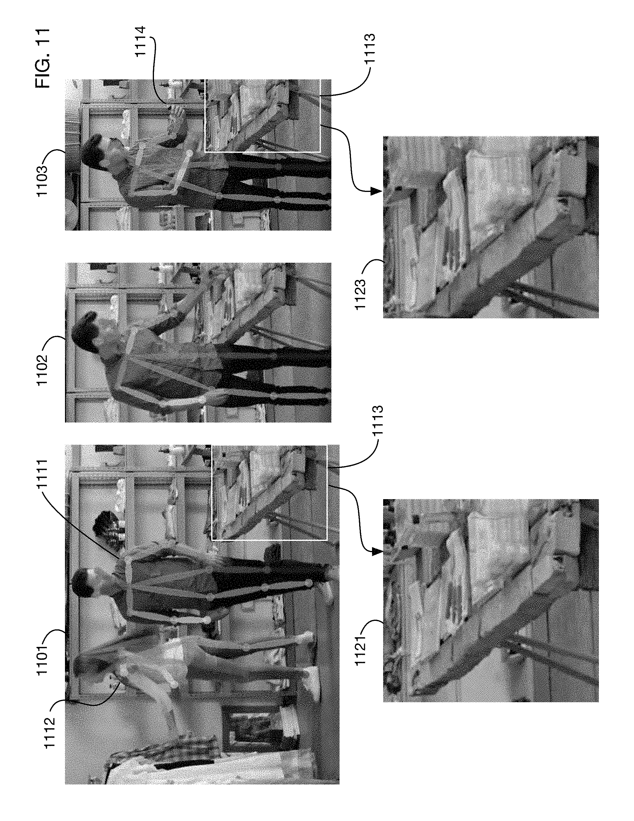
D00013
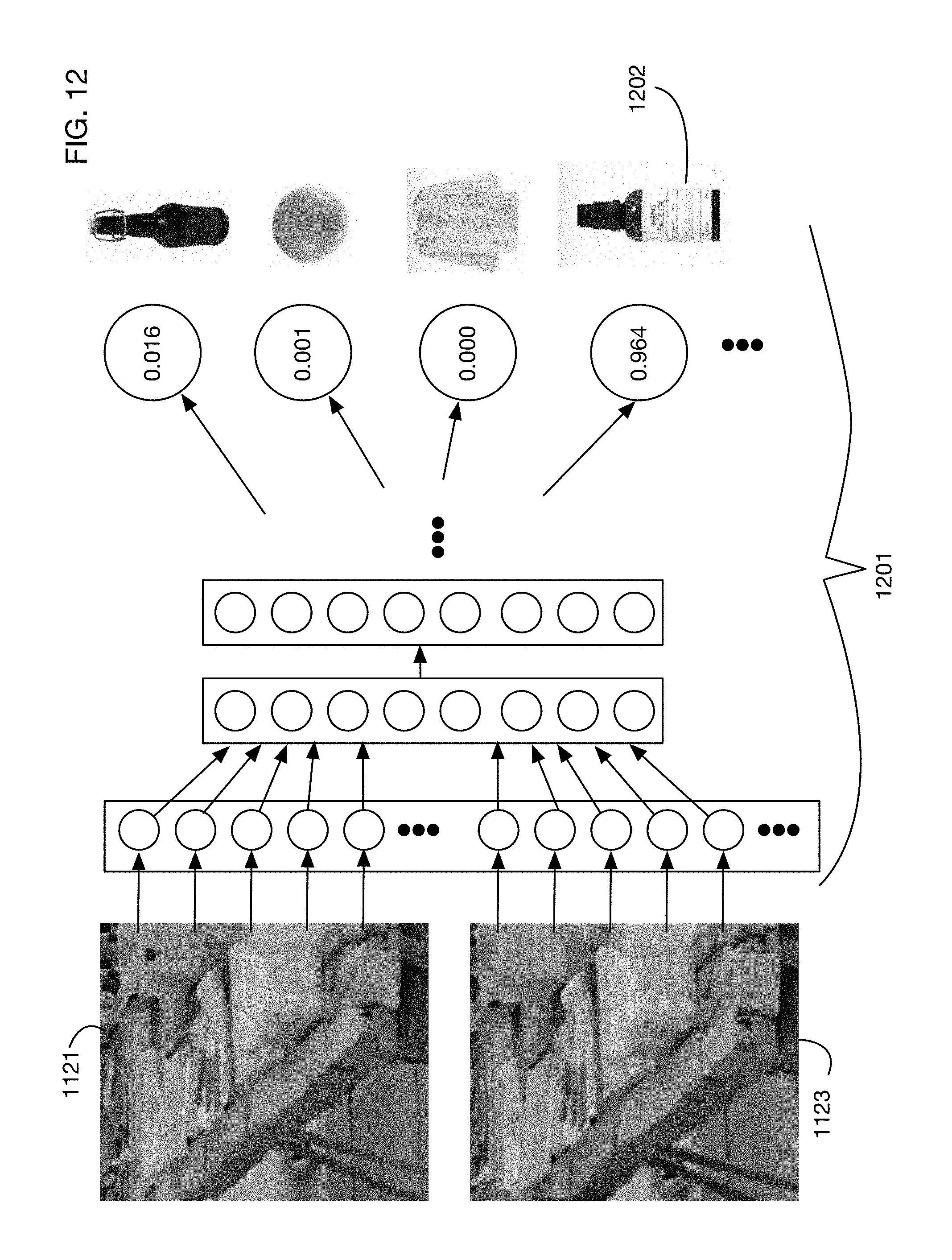
D00014
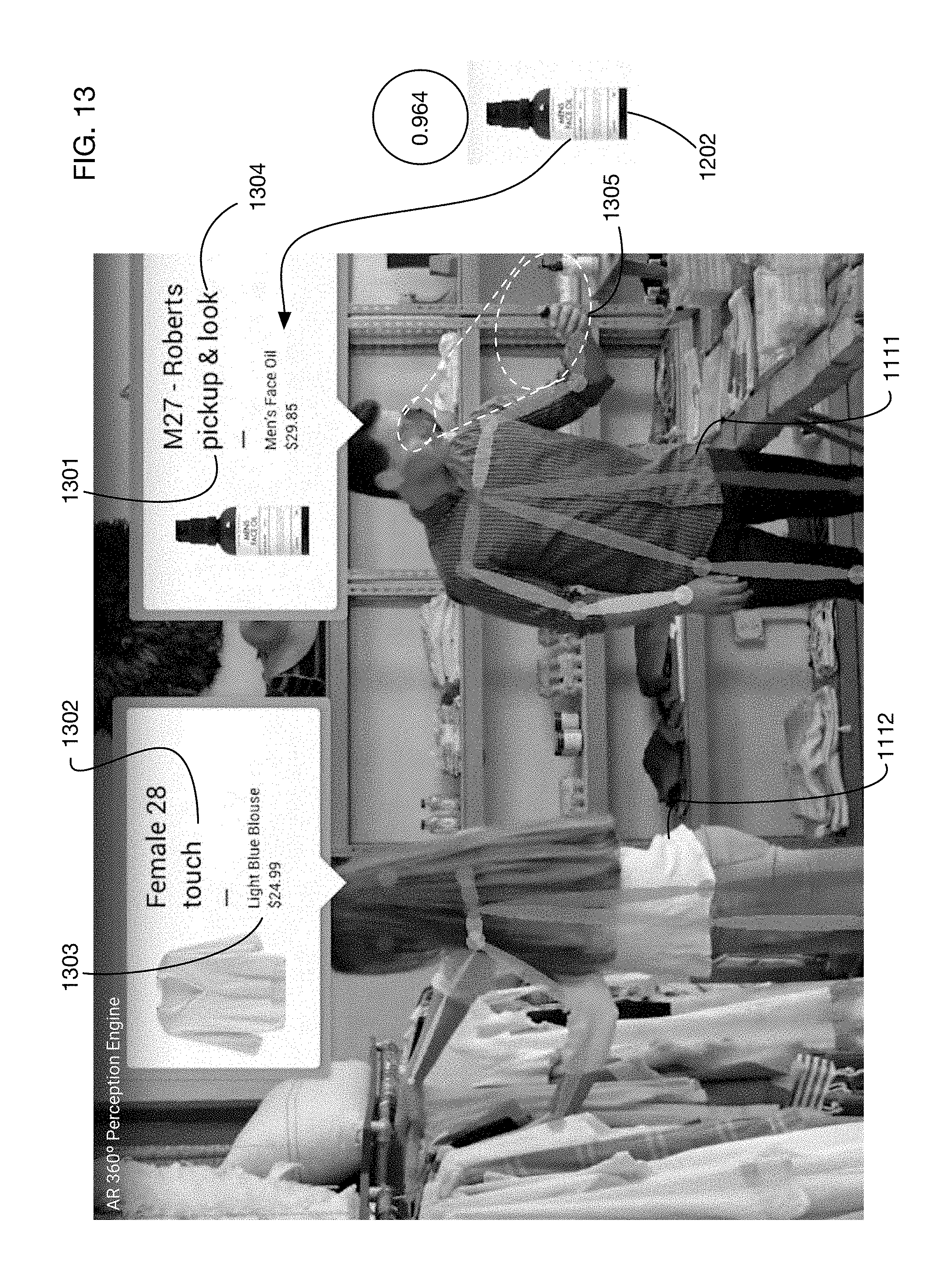
D00015
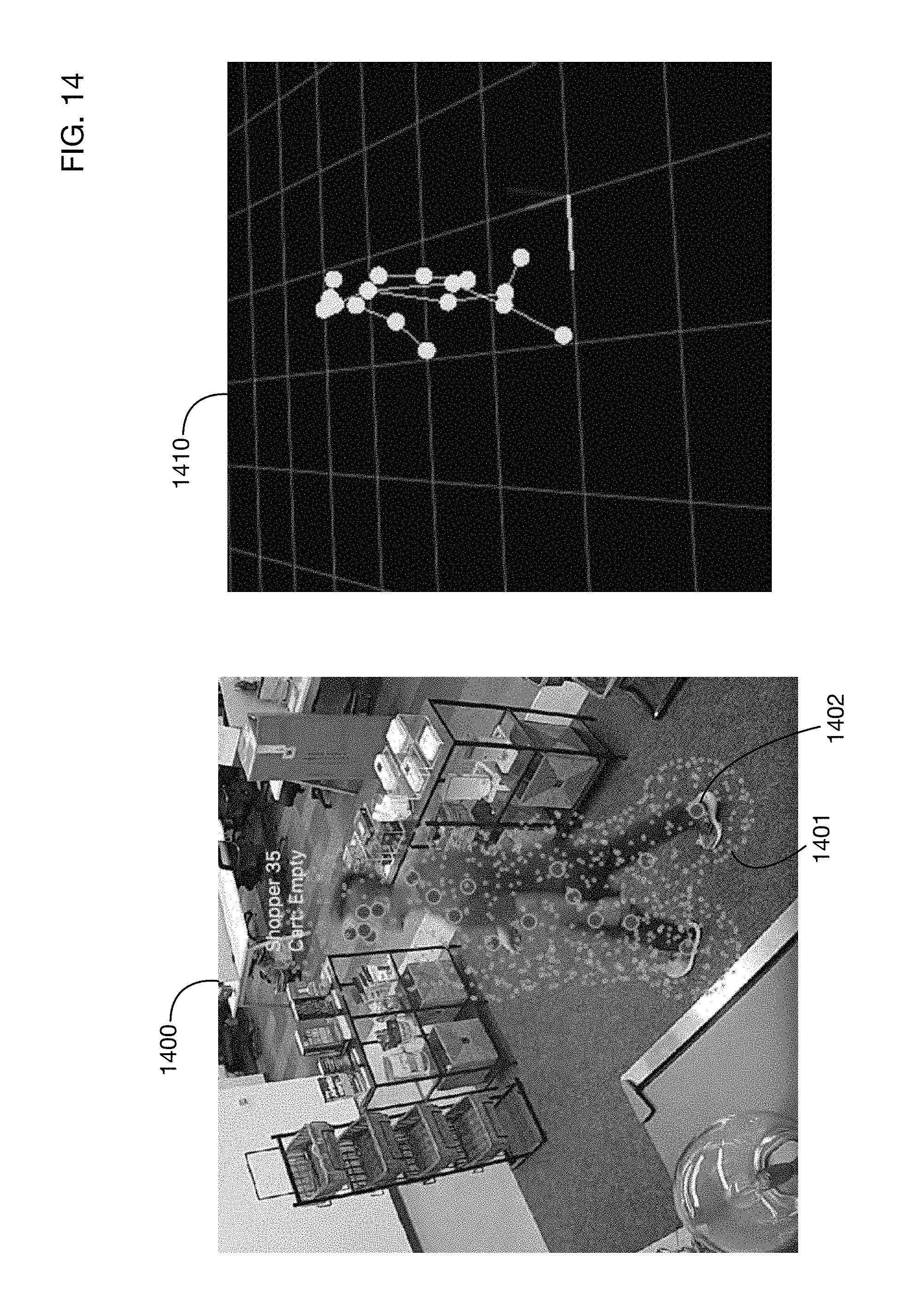
D00016
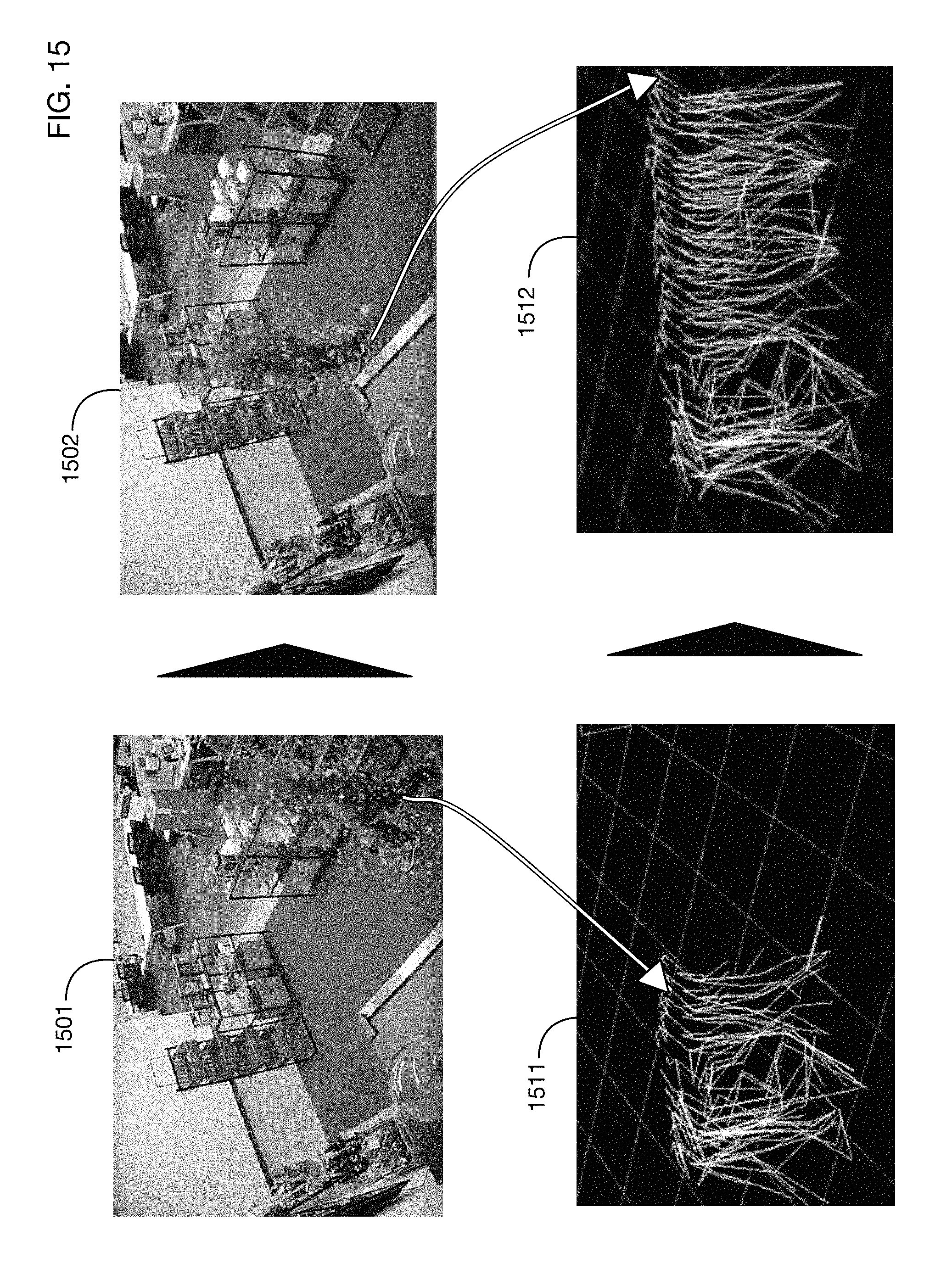
D00017

D00018

D00019
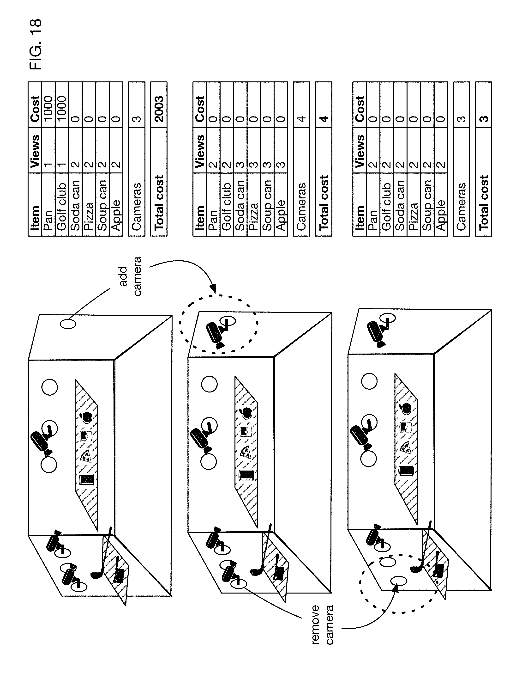
D00020

D00021

D00022

D00023
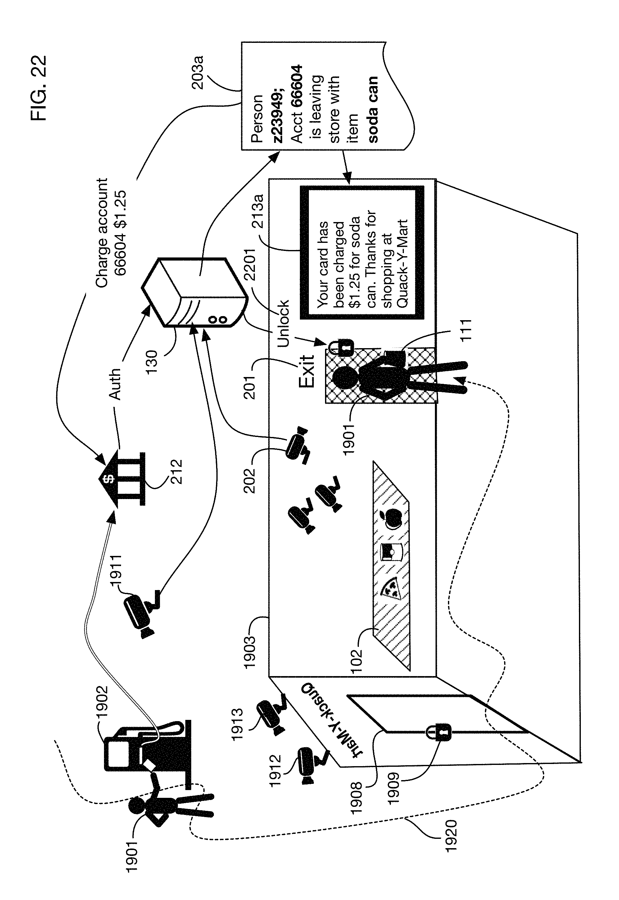
D00024
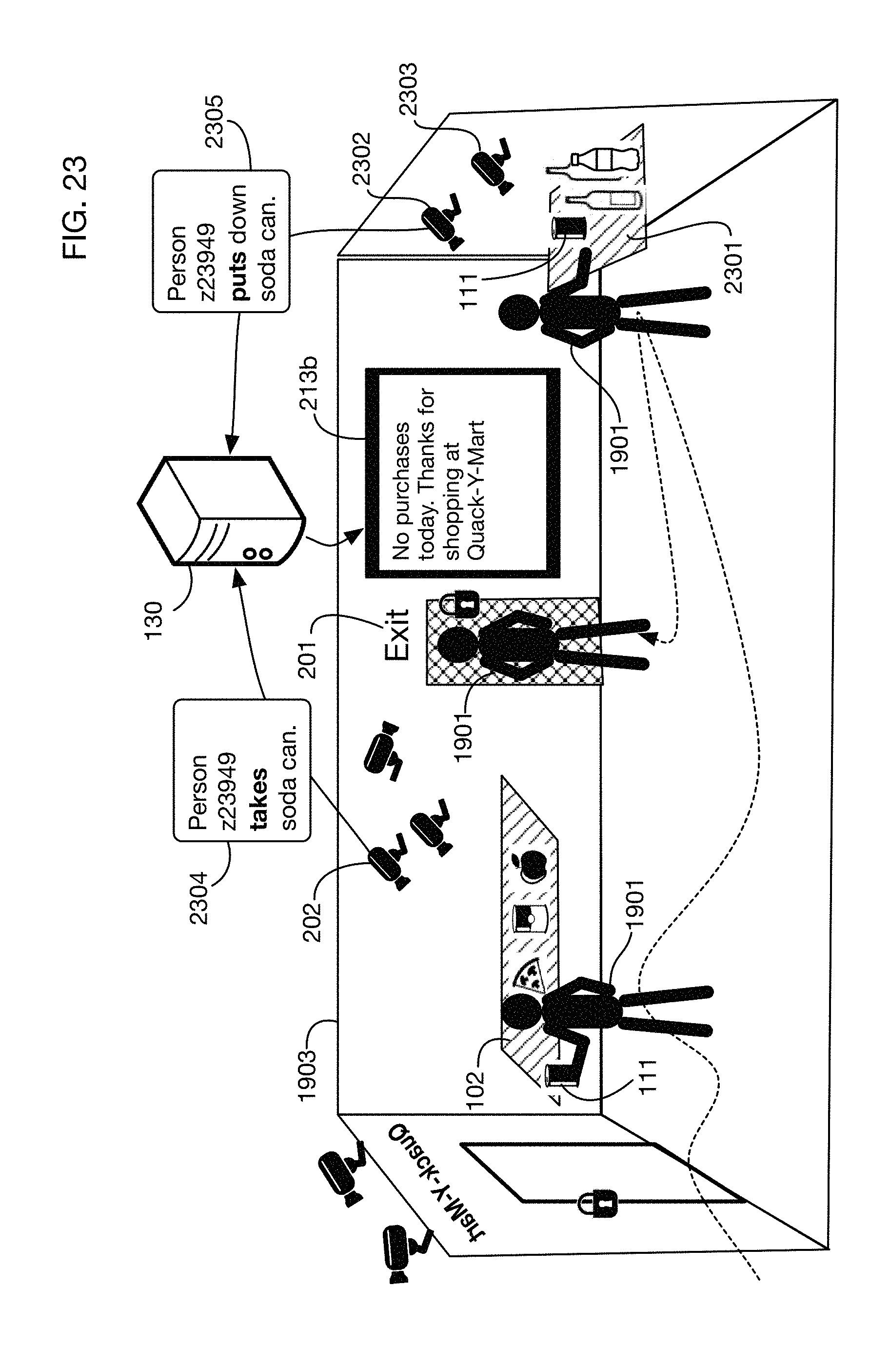
D00025
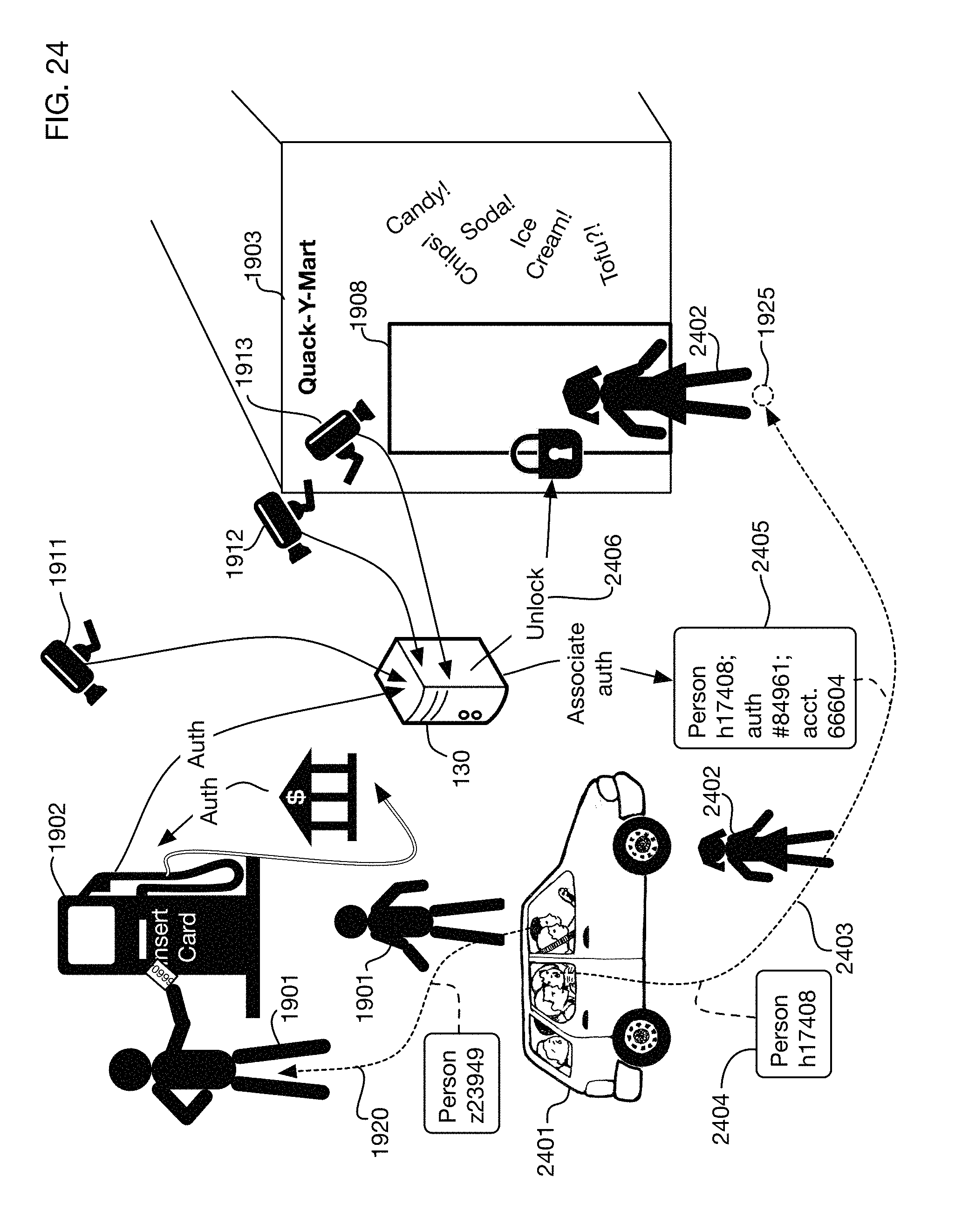
D00026
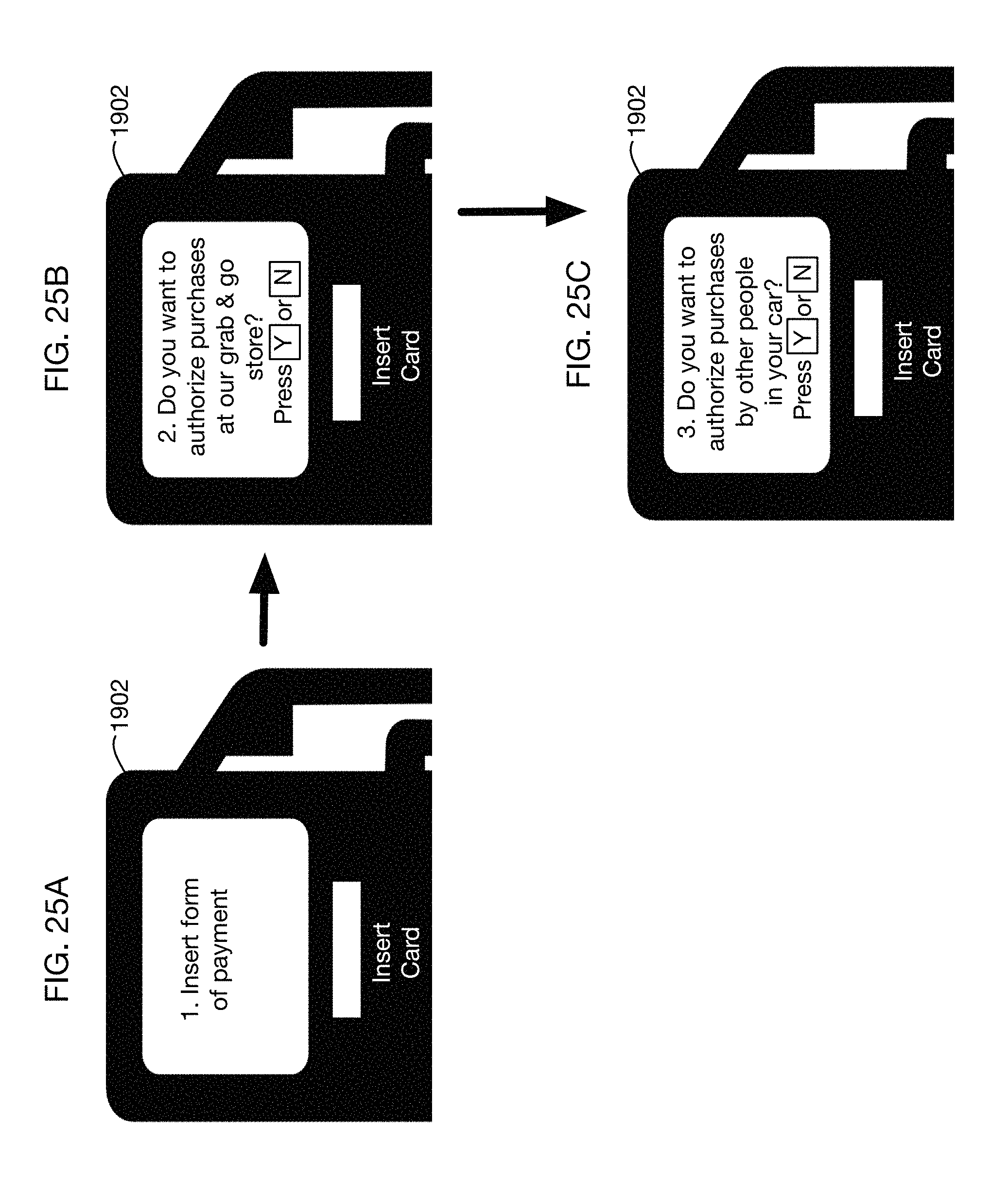
D00027
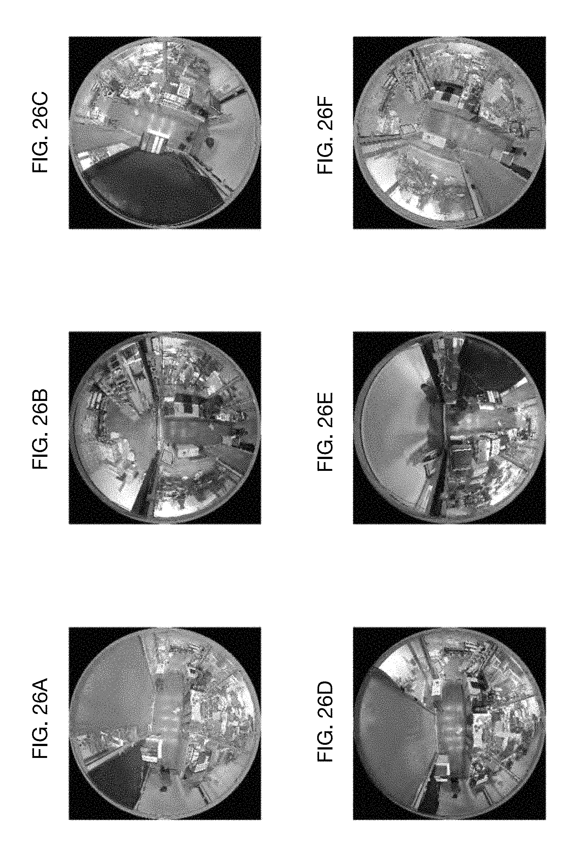
D00028
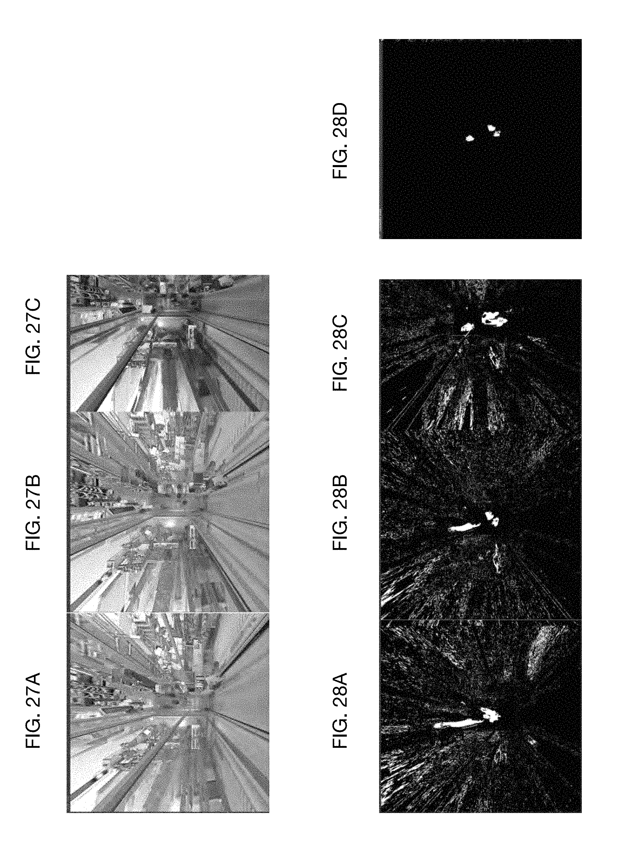
D00029
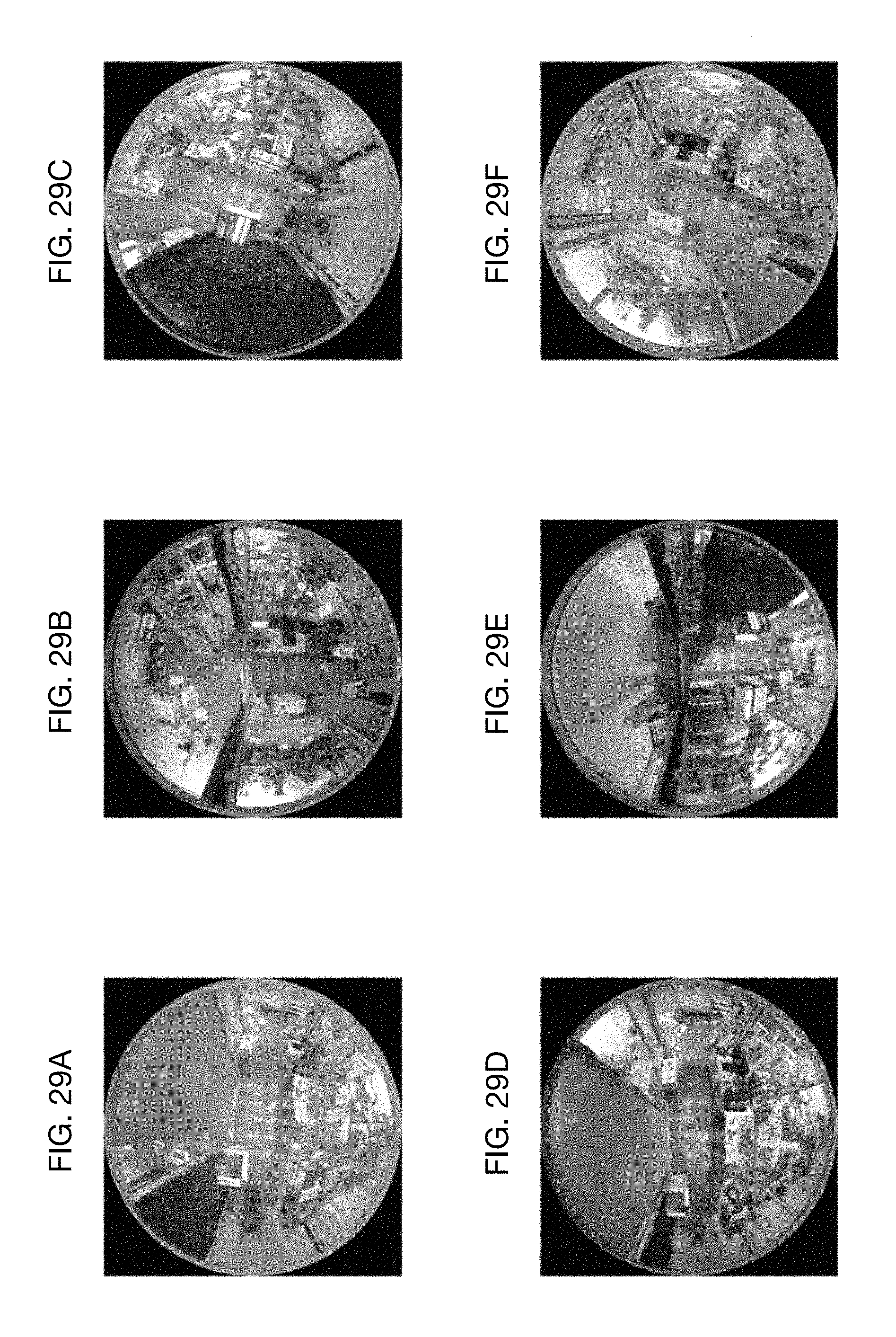
D00030
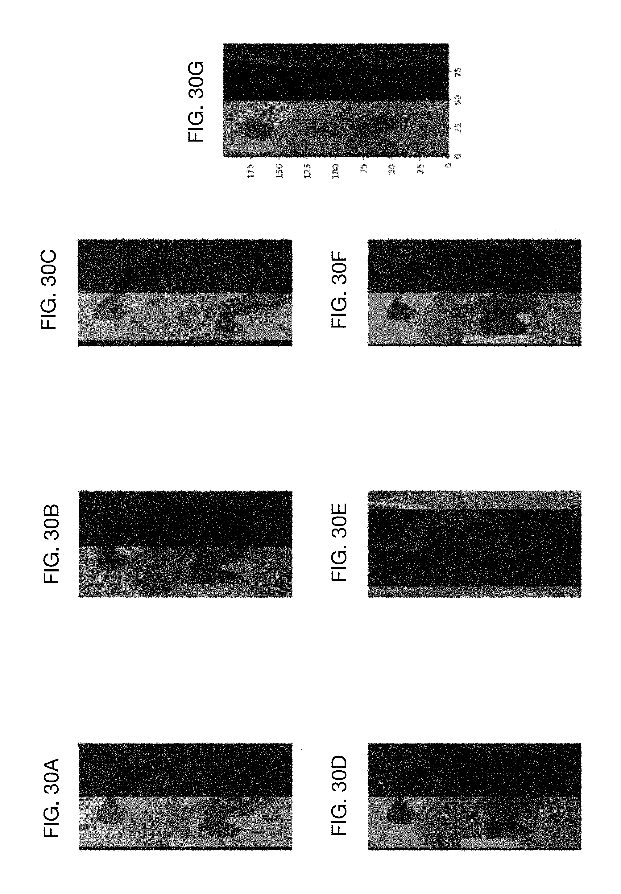
D00031

XML
uspto.report is an independent third-party trademark research tool that is not affiliated, endorsed, or sponsored by the United States Patent and Trademark Office (USPTO) or any other governmental organization. The information provided by uspto.report is based on publicly available data at the time of writing and is intended for informational purposes only.
While we strive to provide accurate and up-to-date information, we do not guarantee the accuracy, completeness, reliability, or suitability of the information displayed on this site. The use of this site is at your own risk. Any reliance you place on such information is therefore strictly at your own risk.
All official trademark data, including owner information, should be verified by visiting the official USPTO website at www.uspto.gov. This site is not intended to replace professional legal advice and should not be used as a substitute for consulting with a legal professional who is knowledgeable about trademark law.