Apparatus and method for controlling vehicles in a platoon
Cremona , et al.
U.S. patent number 10,281,926 [Application Number 15/412,681] was granted by the patent office on 2019-05-07 for apparatus and method for controlling vehicles in a platoon. This patent grant is currently assigned to Bendix Commercial Vehicle Systems LLC. The grantee listed for this patent is Bendix Commercial Vehicle Systems LLC. Invention is credited to Jeffrey M. Carbaugh, Michael D. Cremona.


| United States Patent | 10,281,926 |
| Cremona , et al. | May 7, 2019 |
Apparatus and method for controlling vehicles in a platoon
Abstract
A system for controlling vehicles in a platoon includes a lead vehicle controller on a lead vehicle in the platoon and a following vehicle controller on a following vehicle in the platoon. The lead vehicle controller is adapted to determine a braking distance, based on an initial speed of the lead vehicle and a percent of full service brake application of the lead vehicle, and transmit a braking distance signal indicating the braking distance. The following vehicle controller is adapted to identify the braking distance upon receiving the braking distance signal, determine a percent of full service brake application of the following vehicle based on an initial speed of the following vehicle and the braking distance, and transmit a signal to a following vehicle service brake to apply the following vehicle service brake at the determined percent of full service brake application.
| Inventors: | Cremona; Michael D. (Lakewood, OH), Carbaugh; Jeffrey M. (Avon Lake, OH) | ||||||||||
|---|---|---|---|---|---|---|---|---|---|---|---|
| Applicant: |
|
||||||||||
| Assignee: | Bendix Commercial Vehicle Systems
LLC (Elyria, OH) |
||||||||||
| Family ID: | 62906182 | ||||||||||
| Appl. No.: | 15/412,681 | ||||||||||
| Filed: | January 23, 2017 |
Prior Publication Data
| Document Identifier | Publication Date | |
|---|---|---|
| US 20180210461 A1 | Jul 26, 2018 | |
| Current U.S. Class: | 1/1 |
| Current CPC Class: | G05D 1/0293 (20130101); B60T 8/17 (20130101); G08G 1/161 (20130101); B60T 7/16 (20130101); B60T 7/22 (20130101); G05D 1/0289 (20130101); G08G 1/22 (20130101); B60T 2201/02 (20130101); B60T 2210/32 (20130101); G05D 2201/0213 (20130101) |
| Current International Class: | B60T 7/16 (20060101); G08G 1/16 (20060101); B60T 8/17 (20060101); B60T 7/22 (20060101); G08G 1/00 (20060101); G05D 1/02 (20060101); G05D 1/00 (20060101) |
| Field of Search: | ;701/2 |
References Cited [Referenced By]
U.S. Patent Documents
| 3710385 | January 1973 | Howard et al. |
| 5357438 | October 1994 | Davidian |
| 5948035 | September 1999 | Tomita |
| 5954781 | September 1999 | Slepian et al. |
| 6401024 | June 2002 | Tange et al. |
| 8744652 | June 2014 | Nishinaga |
| 2009/0062987 | March 2009 | Kim et al. |
| 2009/0299594 | December 2009 | Harumoto et al. |
| 2011/0224844 | September 2011 | Farwell |
| 2012/0101713 | April 2012 | Moshchuk et al. |
| 2013/0116861 | May 2013 | Nemoto |
| 2014/0244150 | August 2014 | Boesch et al. |
| 105774780 | Oct 2018 | CN | |||
| 1800982 | Oct 2013 | EP | |||
| 2512576 | Oct 2014 | GB | |||
| 2006074876 | Mar 2006 | JP | |||
| 2006309552 | Nov 2006 | JP | |||
| 2003049975 | Jun 2003 | WO | |||
| 2012105896 | Aug 2012 | WO | |||
| 2016135207 | Sep 2016 | WO | |||
Assistant Examiner: Schneider; Paula L
Attorney, Agent or Firm: Kondas; Brian E. Greenly; Cheryl L. Clair; Eugene E.
Claims
We claim:
1. A controller for controlling a following vehicle in a platoon, the controller comprising: an electrical port adapted to receive and transmit signals, wherein the controller: receives, via the electrical port, a brake activation signal from another vehicle in the platoon, the other vehicle being positioned in front of the following vehicle, identifies a stopping distance of the other vehicle and transmits a first lookup signal to a lookup table on the following vehicle in response to receiving the brake activation signal, wherein the first lookup signal indicates an initial speed of the following vehicle and the identified stopping distance, receives a second lookup signal from the lookup table including a determined percentage of full service brake application of the following vehicle based on the first lookup signal and transmits a brake application signal, via the electrical port, for applying a service brake of the following vehicle to achieve the determined percentage of full service brake application.
2. The controller for controlling a following vehicle in a platoon as set forth in claim 1, wherein: the controller transmits an update lookup signal to update the lookup table based on an actual stopping distance, the initial speed and percentage of full brake application of the following vehicle.
3. The controller for controlling a following vehicle in a platoon as set forth in claim 1, wherein: the wireless RF receiver wirelessly receives the brake activation signal from the other vehicle and transmits the brake activation signal to the electrical port.
4. The controller for controlling a following vehicle in a platoon as set forth in claim 1, wherein: the controller determines an actual stopping distance of the following vehicle based on the initial speed and the determined percentage of full service brake application; and the controller transmits an update lookup signal to the lookup table on the following vehicle, the update lookup signal indicating the initial speed of the following vehicle, the actual stopping distance and the determined percentage of full service brake application.
5. The controller for controlling a following vehicle in a platoon as set forth in claim 1, wherein: the other vehicle is a lead vehicle of the platoon.
6. The controller for controlling a following vehicle in a platoon as set forth in claim 1, wherein: the controller transmits a second following vehicle stop signal, identifying the stopping distance, from the following vehicle to a second following vehicle.
7. A system for controlling vehicles in a platoon, the system comprising: a lead vehicle controller, on a lead vehicle in the platoon, i) that determines a braking distance based on an initial speed of the lead vehicle and a percent of full service brake application of the lead vehicle and ii) transmits a braking distance signal indicating the braking distance; and a following vehicle controller, on a following vehicle in the platoon, i) that identifies the braking distance upon receiving the braking distance signal, ii) determines a percent of full service brake application of the following vehicle based on an initial speed of the following vehicle and the braking distance and iii) transmits a brake application signal to the following vehicle service brake to apply the following vehicle service brake at the determined percent of full service brake application.
8. The system for controlling vehicles in a platoon as set forth in claim 7, further comprising: a lead vehicle speed sensor electrically communicating with the lead vehicle controller, the lead vehicle controller determining the lead vehicle speed based on a lead vehicle speed signal received from the lead vehicle speed sensor and a following vehicle speed sensor electrically communicating with the following vehicle controller, the following vehicle controller determining the following vehicle speed based on a following vehicle speed signal received from the following vehicle speed sensor.
9. The system for controlling vehicles in a platoon as set forth in claim 7, further comprising: a lead vehicle service brake sensor electrically communicating with the lead vehicle controller, the lead vehicle controller identifying a start of a braking event upon receiving an electronic brake actuation signal from the lead vehicle service brake sensor; wherein the lead vehicle controller determines the initial speed of the lead vehicle at the start of the braking event and transmits the braking distance signal based on the initial speed at the start of the braking event.
10. The system for controlling vehicles in a platoon as set forth in claim 7, the lead vehicle controller further comprising: a lead vehicle lookup table electrically communicating with the lead vehicle controller, the lead vehicle controller transmits a lead vehicle first lookup signal to the lead vehicle lookup table, indicating the initial speed of the lead vehicle and the percent of full service brake application of the lead vehicle, and receives a lead vehicle second lookup signal from the lead vehicle lookup table indicating the lead vehicle braking distance.
11. The system for controlling vehicles in a platoon as set forth in claim 10, wherein the lead vehicle controller updates the lead vehicle lookup table.
12. The system for controlling vehicles in a platoon as set forth in claim 11, further comprising: a lead vehicle distance measuring device; a lead vehicle service brake sensor; and a lead vehicle speed sensor; wherein the lead vehicle controller i) receives a lead vehicle brake activation signal from the lead vehicle service brake sensor upon activation of the service brake of the lead vehicle, ii) receives a lead vehicle actual brake distance signal from the lead vehicle distance measuring device indicating the lead vehicle actual braking distance and iii) transmits a lead vehicle update signal to the lead vehicle lookup table to update the lead vehicle lookup table with the lead vehicle actual braking distance based on the lead vehicle initial speed and lead vehicle percent of full service brake application.
13. The system for controlling vehicles in a platoon as set forth in claim 12, further comprising: a following vehicle lookup table; a following vehicle distance measuring device; a following vehicle service brake sensor; and a following vehicle speed sensor; the following vehicle controller i) receives a following vehicle brake activation signal from the following vehicle service brake sensor upon activation of the service brake of the following vehicle, ii) receives a following vehicle actual brake distance signal from the distance measuring device indicating the following vehicle actual braking distance and iii) transmits a following vehicle update signal to the following vehicle lookup table to update the following vehicle lookup table with the following vehicle actual braking distance based on the following vehicle initial speed and following vehicle percent of full service brake application.
14. The system for controlling vehicles in a platoon as set forth in claim 12, wherein: upon receiving the lead vehicle brake activation signal indicating activation of the service brake of the lead vehicle, the lead vehicle controller transmits a lead vehicle actual braking distance start signal to the lead vehicle distance measuring device to begin measuring an actual braking distance of the lead vehicle; and upon receiving a lead vehicle brake event end signal from the lead vehicle speed sensor indicating an end of the braking event, the lead vehicle controller transmits a lead vehicle actual braking distance stop signal to the lead vehicle distance measuring device to stop measuring the actual braking distance, determine the actual braking distance of the lead vehicle and transmit the lead vehicle actual brake distance signal to the lead vehicle controller indicating the actual braking distance.
15. A method for controlling vehicles in a platoon, the method comprising: determining a braking distance of a lead vehicle based on an initial speed of the lead vehicle and a percent of full service brake application of the lead vehicle; transmitting a lead vehicle braking distance signal, indicting the braking distance, from the lead vehicle; receiving the lead vehicle braking distance signal at a following vehicle; determining a percent of full service brake application of the following vehicle based on an initial speed of the following vehicle and the lead vehicle braking distance; and transmitting a following vehicle brake application signal to the following vehicle to apply the following vehicle service brake at the determined percent of full service brake application.
16. The method for controlling vehicles in a platoon as set forth in claim 15, further comprising: determining an initial speed of the lead vehicle.
17. The method for controlling vehicles in a platoon as set forth in claim 15, wherein the step of determining the braking distance comprises: transmitting a lookup signal to a lead vehicle lookup table indicating the initial speed of the lead vehicle and the percent of full service brake application of the lead vehicle; identifying the lead vehicle braking distance, based on the initial speed of the lead vehicle and the percent of full service brake application of the lead vehicle, in the lookup table; and transmitting the lead vehicle braking distance from the lookup table.
18. The method for controlling vehicles in a platoon as set forth in claim 17, further comprising: determining a lead vehicle actual braking distance based on the initial speed of the lead vehicle and the percent of full service brake application of the lead vehicle; and updating the lead vehicle lookup table with the lead vehicle actual braking distance based on the initial speed of the lead vehicle and the percent of full service brake application of the lead vehicle.
19. The method for controlling vehicles in a platoon as set forth in claim 15, further comprising: transmitting the lead vehicle braking distance signal to a second following vehicle.
20. The method for controlling vehicles in a platoon as set forth in claim 19, further comprising: determining a percent of full service brake application of the second following vehicle based on an initial speed of the second following vehicle and the lead vehicle braking distance.
Description
BACKGROUND
The present invention relates to platooning vehicles. It finds particular application in conjunction with controlling vehicles in a platoon and will be described with particular reference thereto. It will be appreciated, however, that the invention is also amenable to other applications.
Platooning involves coupling (e.g., electronically coupling) vehicles together on a roadway. Vehicles in the platoon typically follow other vehicles in the platoon at relatively shorter distances than non-platooning vehicles follow other vehicles. A first vehicle in the platoon is referred to as a "lead" vehicle, and other vehicles in the platoon behind the lead vehicle are referred to as "following" vehicles. Interest in platooning vehicles on public roadways has received increased interest due to the benefits provided. For example, because of the reduced following distances, the platooning vehicles require less roadway space that could also lead to less road congestion. In addition, platooning can result in increased fuel economy of both the lead vehicle and the following vehicles participating in the platoon. Despite the benefits offered by the shorter following distances, each of the following vehicles in the platoon must be able to decelerate quickly enough to avoid colliding with the respective forward vehicle.
Each vehicle in a platoon commonly has a unique braking performance. Determining the order and correct spacing of vehicles to avoid a following vehicle from colliding with a forward vehicle based on each vehicle's individual braking performance may be complicated.
The present invention provides a new and improved apparatus and method for updating a lookup table for a vehicle in a platoon and for controlling vehicles in the platoon.
SUMMARY
In one aspect of the present invention, it is contemplated that a controller controls a following vehicle in a platoon. The controller is adapted to receive a signal from another vehicle in the platoon, which is positioned in front of the following vehicle, identify a stopping distance of the other vehicle based on the signal, determine a percentage of full service brake application of the following vehicle based on an initial speed of the following vehicle and the identified stopping distance, and transmit a signal for applying a service brake of the following vehicle to achieve the percentage of full service brake application.
BRIEF DESCRIPTION OF THE DRAWINGS
In the accompanying drawings which are incorporated in and constitute a part of the specification, embodiments of the invention are illustrated, which, together with a general description of the invention given above, and the detailed description given below, serve to exemplify the embodiments of this invention.
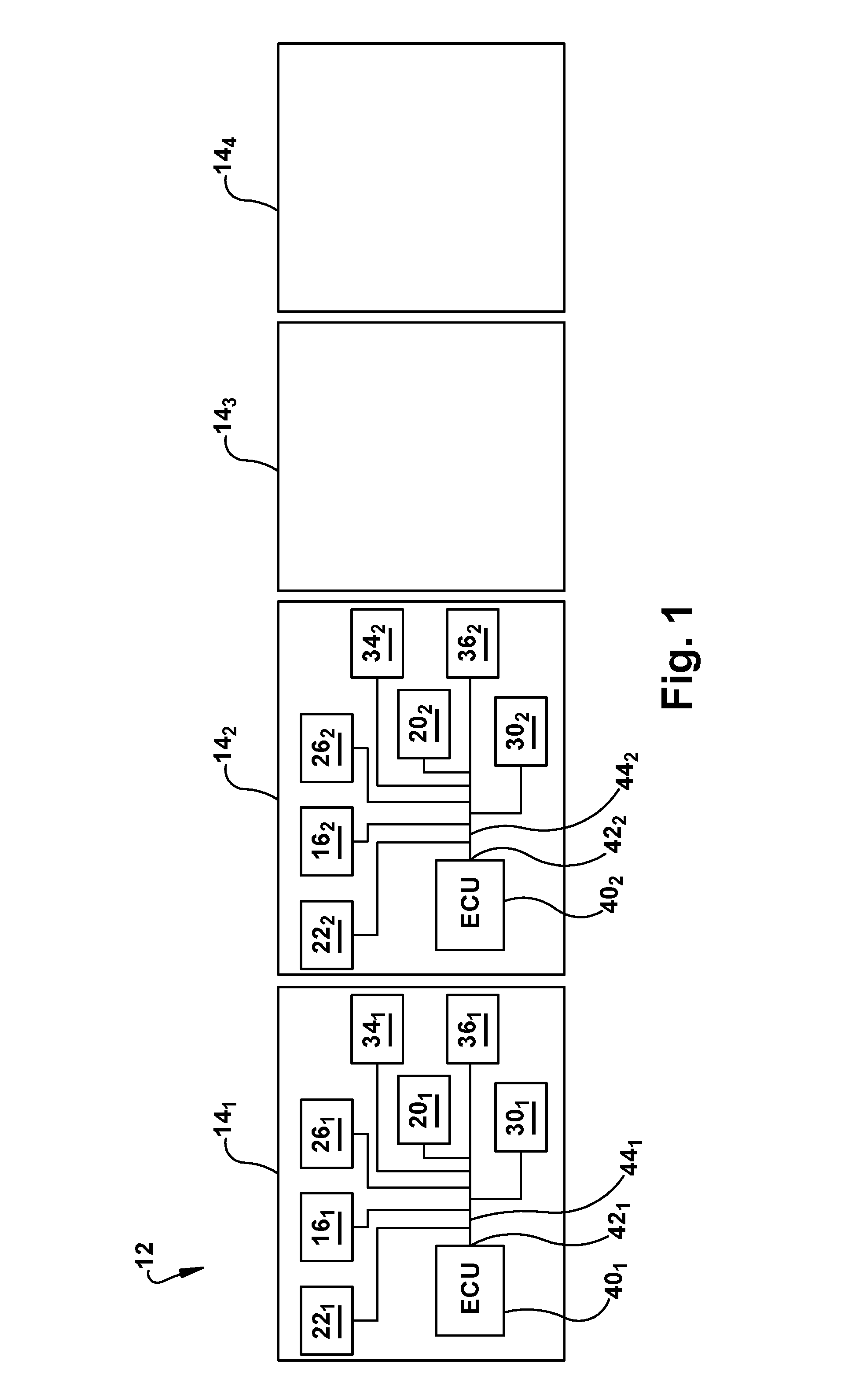
FIG. 1 illustrates a schematic representation of a simplified component diagram of an exemplary platoon of vehicles in accordance with one embodiment of an apparatus illustrating principles of the present invention;
FIG. 2 is an exemplary methodology of updating a lookup table in accordance with one embodiment illustrating principles of the present invention; and
FIG. 3 is an exemplary methodology of controlling vehicles in a platoon in accordance with one embodiment illustrating principles of the present invention.
DETAILED DESCRIPTION OF ILLUSTRATED EMBODIMENT
With reference to FIG. 1, a simplified component diagram of an exemplary platoon 12 is illustrated in accordance with one embodiment of the present invention. The platoon 12 includes a plurality of individual vehicle 14. In the illustrated embodiment, the platoon 12 includes four (4) vehicles 14.sub.1,2,3,4 (collectively 14). The first vehicle 14.sub.1 is designated as the lead vehicle of the platoon 12 and the remaining vehicles 14.sub.2,3,4 are referred to as following vehicles of the platoon 12. In addition, each of the vehicles 14.sub.1,2,3 is considered to be a "forward vehicle" to the respective "following vehicles" 14.sub.2,3,4.
Each of the vehicles 14.sub.1,2,3,4 includes a respective distance measuring device 16.sub.1,2,3,4 (collectively 16), a respective lookup table 20.sub.1,2,3,4 (collectively 20), a respective brake pedal 22.sub.1,2,3,4 (collectively 22), a brake pedal sensor 24.sub.1,2,3,4 (collectively 24), a vehicle speed sensor 26.sub.1,2,3,4 (collectively 26), service brakes 30.sub.1,2,3,4 (collectively 30), service brake sensors 32.sub.1,2,3,4 (collectively 32), a wireless radio-frequency (RF) transmitter 34.sub.1,2,3,4 (collectively 34), a wireless RF receiver 36.sub.1,2,3,4 (collectively 36), and an electronic control unit 40.sub.1,2,3,4 (collectively 40). Each of the brake pedals 22 is depressed by an operator of the respective vehicle 14 for engaging the service brakes 30 on that vehicle 14. Each of the brake pedal sensors 24 transmits a respective electronic signal when the brake pedal 22 on the same vehicle 14 is depressed.
Each of the distance measuring devices 16, the lookup tables 20, the brake pedal sensors 24, the speed sensors 26, the transmitters 34, and the receivers 36 electronically communicate with the ECU 40 on the respective vehicle 14 (e.g., the same vehicle 14) via a respective electrical port 42.sub.1,2,3,4 (collectively 42) on the ECU 40 and a respective vehicle communication bus 44.sub.1,2,3,4 (collectively 44). In the illustrated embodiment, the distance measuring devices 16, the lookup tables 20, the brake pedal sensors 24, the speed sensors 26, the transmitters 34, and the receivers 36 electronically communicate with the ECU 40 on the same vehicle 14 via an electrically wired connection (e.g., via the vehicle communication bus 44). However, other embodiments, in which the distance measuring devices 16, the lookup tables 20, the brake pedal sensors 24, the speed sensors 26, the transmitters 34, and the receivers 36 communicate with the ECU 40 on the same vehicle 14 via a wireless RF connection are also contemplated. It is contemplated that the distance measuring devices 16 are global positioning systems (GPSs), accelerometers, etc.
The lookup tables 20 store stopping distances (e.g., deceleration distances) at various speeds and percent of full brake applications for the respective vehicle 14. For example, the 20.sub.1 stores stopping distances for the lead vehicle 14.sub.1 at various speeds and percent of full brake applications. In a more specific example, the 20.sub.1 may include a stored entry indicating that the lead vehicle 14.sub.1 has a stopping distance of 200 feet when a 30% brake application (e.g., 30% of a full brake application) is applied at 30 miles per hour (mph).
The lookup table 20.sub.1 is continuously updated as braking events occur. With reference to FIG. 2, an exemplary methodology of the system shown in FIG. 1 for continuously updating a lookup table 20 (e.g., the lookup table 20.sub.1 on the lead vehicle 14.sub.1) as braking events occur is illustrated. As illustrated, the blocks represent functions, actions and/or events performed therein. It will be appreciated that electronic and software systems involve dynamic and flexible processes such that the illustrated blocks and described sequences can be performed in different sequences. It will also be appreciated by one of ordinary skill in the art that elements embodied as software may be implemented using various programming approaches such as machine language, procedural, object-oriented or artificial intelligence techniques. It will further be appreciated that, if desired and appropriate, some or all of the software can be embodied as part of a device's operating system.
It is contemplated that each of the respective ECUs 40 act as a means for controlling the vehicle 14 (e.g., by controlling the stopping distance) in the platoon 12.
With reference to FIGS. 1 and 2, the method of updating the lookup table 20.sub.1 starts in a step 210. As an example, for each braking event the ECU 40.sub.1 determines when an operator of the lead vehicle 14.sub.1 depresses the brake pedal 22.sub.1 associated with the service brake 30.sub.1. More specifically, in a step 212, the brake pedal 22.sub.1 transmits an electronic signal to the ECU 40.sub.1 indicating that the brake pedal 22 has been depressed, which indicates the beginning of the braking event. After receiving the electronic signal from the brake pedal 22.sub.1, in a step 214 the ECU 40 transmits an electronic signal to the distance measuring device 16.sub.1 to begin measuring the distance of the braking event.
The ECU 40.sub.1 also determines the percentage of full application the service brake 30 is applied during the event. More specifically, in a step 216, the service brake 30 transmits a signal to the ECU 40.sub.1 indicating the percentage of full application the service brake 30. In addition, in a step 220, the ECU 40.sub.1 determines the initial speed of the lead vehicle 14.sub.1 upon receiving an electronic speed signal at the beginning of the braking event from the vehicle speed sensor 26.sub.1. After the braking event (e.g., after the vehicle 14.sub.1 has stopped braking), the ECU 40.sub.1 transmits an electronic signal, in a step 222, to the distance measuring device 16.sub.1 which triggers the distance measuring device 16.sub.1 to transmit an electronic signal, in a step 224, to the ECU 40.sub.1 indicating the distance the vehicle 14.sub.1 traveled since the beginning of the braking event.
Then, the ECU 40.sub.1 transmits, in a step 226, electronic signals to the lookup table 20.sub.1 causing the initial speed of the vehicle (e.g., at the beginning of the braking event), the distance of the braking event (e.g., the stopping distance) and the percentage of full brake application to be stored in the lookup table 20.sub.1. The method of updating the lookup table 20.sub.1 stops in a step 230. Since the above process is repeated for each braking event, the lookup table 20.sub.1 is said to be continuously updated with the vehicle's 14 braking profile using the self-learning process described above.
Although the continuous update process has been described only with reference to the lead vehicle 14.sub.1, it is to be understood the respective lookup tables 20.sub.1,2,3,4 in each of the vehicles 14.sub.1,2,3,4 is continuously updated with the vehicle's braking profile as described above.
With reference to FIG. 3, an exemplary methodology of the system shown in FIG. 1 for controlling the vehicles 14 in the platoon 12 is illustrated. As illustrated, the blocks represent functions, actions and/or events performed therein. It will be appreciated that electronic and software systems involve dynamic and flexible processes such that the illustrated blocks and described sequences can be performed in different sequences. It will also be appreciated by one of ordinary skill in the art that elements embodied as software may be implemented using various programming approaches such as machine language, procedural, object-oriented or artificial intelligence techniques. It will further be appreciated that, if desired and appropriate, some or all of the software can be embodied as part of a device's operating system.
With reference to FIGS. 1 and 3, the method for controlling the vehicles 14 in the platoon 12 starts in a step 310. When the operator of the lead vehicle 14.sub.1 depresses the brake pedal 22.sub.1, the brake pedal sensor 24.sub.1 transmits, in a step 312, an electronic signal to the ECU 40.sub.1 indicating a braking event is beginning. After receiving the electronic signal from the brake pedal sensor 24.sub.1, the ECU 40.sub.1 receives, in a step 314, an electronic signal from the service brake sensor 32.sub.1 indicating a percentage of full braking that the service brakes 30.sub.1 are currently applied. The ECU 40.sub.1 also receives, in a step 316, an electronic signal from the speed sensor 26.sub.1 indicating the current speed of the vehicle 14.sub.1. Then, in a step 320, the ECU 40.sub.1 accesses the lookup table 20.sub.1 to identify the stopping distance of the vehicle 14.sub.1 based on the current percentage of full braking and speed.
The lead vehicle 14.sub.1 then transmits, in a step 322, signals indicating the stopping distance via the wireless transmitter 34.sub.1 on the lead vehicle 14.sub.1. The ECU 40.sub.2 on the following vehicle 14.sub.2 receives, in a step 324, the signals indicating the stopping distance of the lead vehicle 14.sub.1 via the wireless receiver 36.sub.2 on the following vehicle 14.sub.2.
The ECU 40.sub.2 on the following vehicle 14.sub.2 then receives, in a step 326, signals indicating the speed of the following vehicle 14.sub.2 from a speed sensor 26.sub.2 on the following vehicle 14.sub.2. Next, the ECU 40.sub.2 accesses, in a step 330 the lookup table 20.sub.2 to identify the percentage of full braking that service brakes 30.sub.2 on the following vehicle 14.sub.2 need to be applied to stop the following vehicle 14.sub.2 in the same stopping distance received from the lead vehicle 14.sub.1.
The method for controlling the vehicles 14 in the platoon 12 stops in a step 332.
Although the steps 310-332 for controlling the vehicles 14 in the platoon 12 only describe controlling the second vehicle 14.sub.2 (e.g., the following vehicle) based on an electronic signal received from the lead vehicle 14.sub.1, it is to be understood the stopping distance transmitted from the lead vehicle 14.sub.1 is also received by the other vehicles (e.g., the following vehicles 14.sub.3,4) in the platoon 12.
In another embodiment, it is contemplated that once the second vehicle 14.sub.2 (e.g., following vehicle) in the platoon 12 receives the electronic signal from the lead vehicle 14.sub.1 indicating the stopping distance, the second vehicle 14.sub.2 in the platoon 12 transmits an electronic signal to the third vehicle 14.sub.3 (e.g., following vehicle) indicating the stopping distance, etc. Therefore, in either embodiment, all of the following vehicles 14.sub.2,3,4 in the platoon 12 are controlled by a vehicle in front of the respective following vehicle 14.sub.2,3,4 (e.g., either immediately in front of the respective following vehicle 14.sub.2,3,4 or by another vehicle in the platoon that is not immediately in front of the respective following vehicle 14.sub.2,3,4). In other words, each of the following vehicles 14.sub.2,3,4 in the platoon 12 receives an electronic signal, which indicates the stopping distance, from another vehicle in the platoon 12 that is in front of the respective following vehicle 14.sub.2,3,4. In addition, the other vehicles 14.sub.3,4 (e.g., following vehicle) determine the respective percentages of full braking of service brakes 30.sub.3,4 on those vehicles 14.sub.3,4 in a similar manner described above with regard to the second vehicle 14.sub.2 in the steps 310-332.
While the present invention has been illustrated by the description of embodiments thereof, and while the embodiments have been described in considerable detail, it is not the intention of the applicants to restrict or in any way limit the scope of the appended claims to such detail. Additional advantages and modifications will readily appear to those skilled in the art. Therefore, the invention, in its broader aspects, is not limited to the specific details, the representative apparatus, and illustrative examples shown and described. Accordingly, departures may be made from such details without departing from the spirit or scope of the applicant's general inventive concept.
* * * * *
D00000
D00001
D00002
D00003
XML
uspto.report is an independent third-party trademark research tool that is not affiliated, endorsed, or sponsored by the United States Patent and Trademark Office (USPTO) or any other governmental organization. The information provided by uspto.report is based on publicly available data at the time of writing and is intended for informational purposes only.
While we strive to provide accurate and up-to-date information, we do not guarantee the accuracy, completeness, reliability, or suitability of the information displayed on this site. The use of this site is at your own risk. Any reliance you place on such information is therefore strictly at your own risk.
All official trademark data, including owner information, should be verified by visiting the official USPTO website at www.uspto.gov. This site is not intended to replace professional legal advice and should not be used as a substitute for consulting with a legal professional who is knowledgeable about trademark law.