Air data probe with improved performance at angle of attack operation
Johnson , et al.
U.S. patent number 10,281,303 [Application Number 14/665,007] was granted by the patent office on 2019-05-07 for air data probe with improved performance at angle of attack operation. This patent grant is currently assigned to Rosemount Aerospace, Inc.. The grantee listed for this patent is Rosemount Aerospace, Inc.. Invention is credited to Aaron A Cusher, Timothy Thomas Golly, Paul Robert Johnson, Brian Daniel Matheis, Greg Seidel.


| United States Patent | 10,281,303 |
| Johnson , et al. | May 7, 2019 |
Air data probe with improved performance at angle of attack operation
Abstract
An air data probe has a pitot tube with a tap at a forward end that defines an inner flow path. The inner flow path decreases in the cross-sectional area until reaching a throat. The inner flow path has cross-sections that are generally cylindrical and also has sections of removed material.
| Inventors: | Johnson; Paul Robert (Prior Lake, MN), Cusher; Aaron A (Eagan, MN), Golly; Timothy Thomas (Lakeville, MN), Matheis; Brian Daniel (Lakeville, MN), Seidel; Greg (Farmington, MN) | ||||||||||
|---|---|---|---|---|---|---|---|---|---|---|---|
| Applicant: |
|
||||||||||
| Assignee: | Rosemount Aerospace, Inc.
(Burnsville, MN) |
||||||||||
| Family ID: | 55589773 | ||||||||||
| Appl. No.: | 14/665,007 | ||||||||||
| Filed: | March 23, 2015 |
Prior Publication Data
| Document Identifier | Publication Date | |
|---|---|---|
| US 20160282158 A1 | Sep 29, 2016 | |
| Current U.S. Class: | 1/1 |
| Current CPC Class: | B64D 45/00 (20130101); G01P 5/165 (20130101); G01F 1/46 (20130101) |
| Current International Class: | G01F 1/46 (20060101); B64D 45/00 (20060101); G01P 5/165 (20060101) |
References Cited [Referenced By]
U.S. Patent Documents
| 2554634 | May 1951 | Paine et al. |
| 2861419 | November 1958 | Hausmann |
| 3482445 | December 1969 | DeLeo et al. |
| 3514999 | June 1970 | Mejean et al. |
| 4121088 | October 1978 | Doremus et al. |
| 4154256 | May 1979 | Miller |
| 4259435 | March 1981 | Broer et al. |
| 4372170 | February 1983 | Dehart |
| 4718273 | January 1988 | McCormack |
| 4730487 | March 1988 | DeLeo et al. |
| 4782007 | November 1988 | Ferrier |
| 5043558 | August 1991 | Byles |
| 5302026 | April 1994 | Phillips |
| 5319970 | June 1994 | Peterson et al. |
| 5369993 | December 1994 | Hagen |
| 5466067 | November 1995 | Hagen et al. |
| 5628565 | May 1997 | Hagen et al. |
| 6070475 | June 2000 | Muelhauser et al. |
| 6143378 | November 2000 | Harwell et al. |
| 6430996 | August 2002 | Anderson et al. |
| 6588285 | July 2003 | Vozhdaev |
| 7777155 | August 2010 | Twelves, Jr. et al. |
| 7941805 | May 2011 | Dillenberger et al. |
| 8383985 | February 2013 | Twelves, Jr. et al. |
| 8678802 | March 2014 | Jenko |
| 8691333 | April 2014 | Godfrey et al. |
| 2004/0177683 | September 2004 | Ice |
| 2007/0064766 | March 2007 | Benning |
| 2008/0285620 | November 2008 | Benning |
| 2014/0116154 | May 2014 | Seidel |
| 2015/0059465 | March 2015 | Leblond et al. |
| 2015/0177032 | June 2015 | Schober |
| 2016/0304210 | October 2016 | Wentland |
| 1457765 | Sep 2004 | EP | |||
| 2728364 | May 2014 | EP | |||
Other References
|
European Search Report for European Application No. 16162062.0 dated Sep. 16, 2016. cited by applicant . Partial European Search Report for European Application No. 16162062.0 dated Jun. 1, 2016. cited by applicant. |
Primary Examiner: Patel; Harshad R
Attorney, Agent or Firm: Carlson, Gaskey & Olds, P.C.
Claims
The invention claimed is:
1. An air data probe comprising: a pitot tube having a tap with a forward end, and defining an inner flow path, the inner flow path decreasing in cross-sectional area until reaching a throat; said inner flow path having cross-sections which are generally cylindrical in cross-sections; wherein said inner flow path includes at least one bleed hole extending from an outer periphery of said pitot tube to communicate air from said inner flow path to said outer periphery, and outwardly of said pitot tube; and wherein an airflow downstream of said throat, moving into a passage and to a pressure tap, said pressure tap in communication with a control, and said control programmed to translate a tapped pressure into an air speed of an associated aircraft body.
2. The air data probe as set forth in claim 1, wherein an inlet of said at least one bleed hole is upstream of said throat.
3. The air data probe as set forth in claim 2, wherein there are a plurality of said at least one bleed hole.
4. The air data probe as set forth in claim 1, wherein the communication of air from the inner flow path to the outer periphery, and outwardly of the pitot tube eliminating a recirculation and boundary layer separation.
Description
BACKGROUND OF THE INVENTION
This application relates to an air data probe for use in aircraft applications wherein its performance is improved during certain operational conditions of an associated aircraft.
Modern aircraft are becoming more sophisticated and require precise information. Controls for modern aircraft must know an air speed with accuracy. As part of determining the air speed, an air data probe is often mounted on an aircraft body.
Air data probes take in air and evaluate that air to determine air speed and other parameters (as examples, altitude, angle of attack, angle of sideslip of an aircraft carrying the probe, etc.).
The requirements for such air data probes are challenging, especially when utilized in environments including ice crystals. Also, when an associated aircraft is operating at a pronounced angle of attack, air recirculation and boundary layers separation may incur within an opening or tap into the air data probe. For the air data probe to provide accurate information, total pressure recovery requirements remain unchanged and, thus, the air recirculation and boundary layer separation raise challenges.
The air data probe typically includes a pitot tube which provides the tap for receiving the air. The challenges mentioned above with regard to recirculation and boundary layer separation occur adjacent to the pitot tube tap.
SUMMARY OF THE INVENTION
An air data probe has a pitot tube with a tap at a forward end that defines an inner flow path. The inner flow path decreases in the cross-sectional area until reaching a throat. The inner flow path has cross-sections that are generally cylindrical and also has sections of removed material. Other embodiment have unique shapes.
These and other features may be best understood from the following drawings and specification.
BRIEF DESCRIPTION OF THE DRAWINGS
FIG. 1A shows an existing air data probe mounted on an aircraft.
FIG. 1B shows an operational challenge with the existing air data probes.
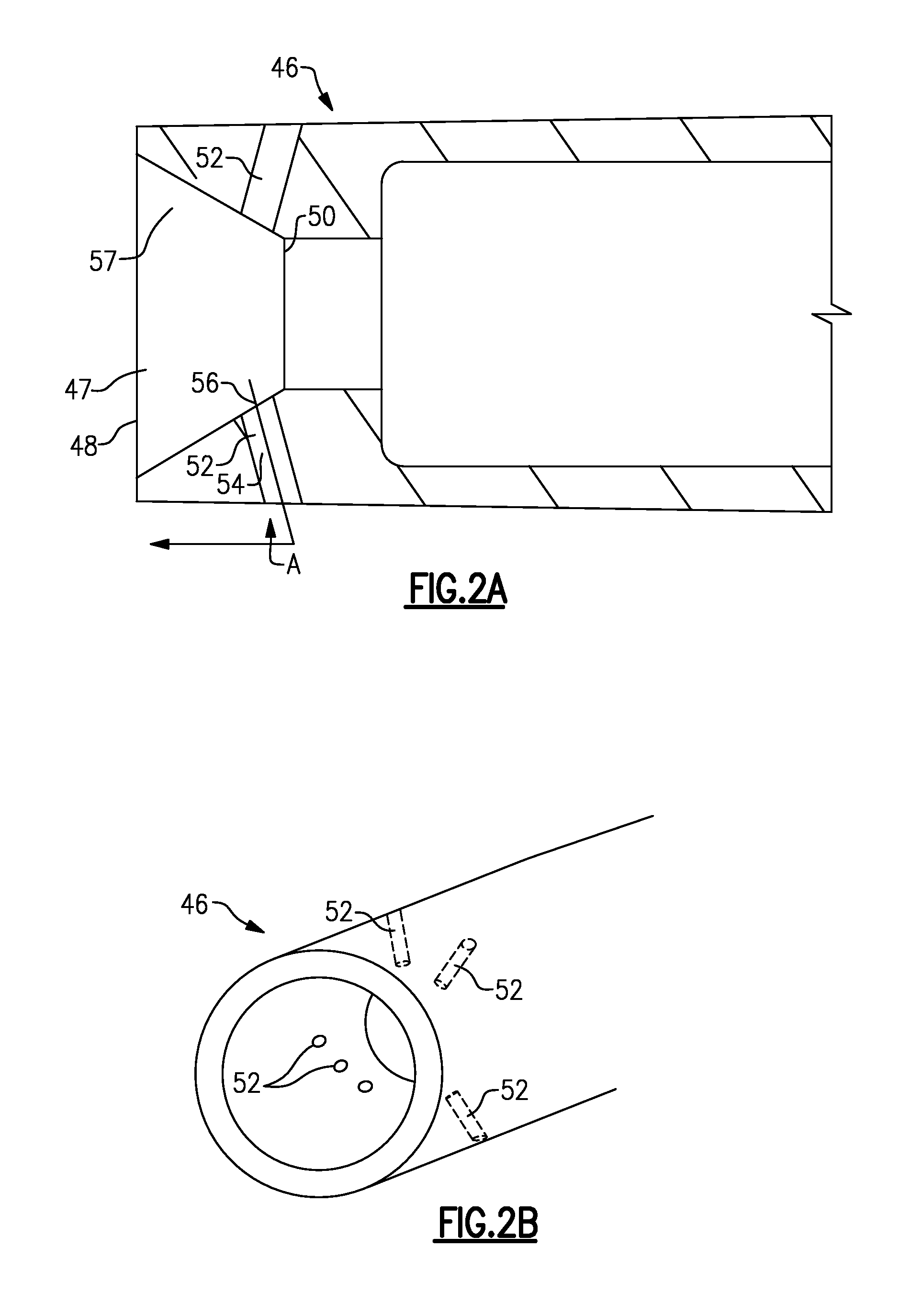
FIG. 2A shows a first embodiment.
FIG. 2B is another view of the first embodiment.
FIG. 2C illustrates an operational benefit of the FIG. 2A embodiment.
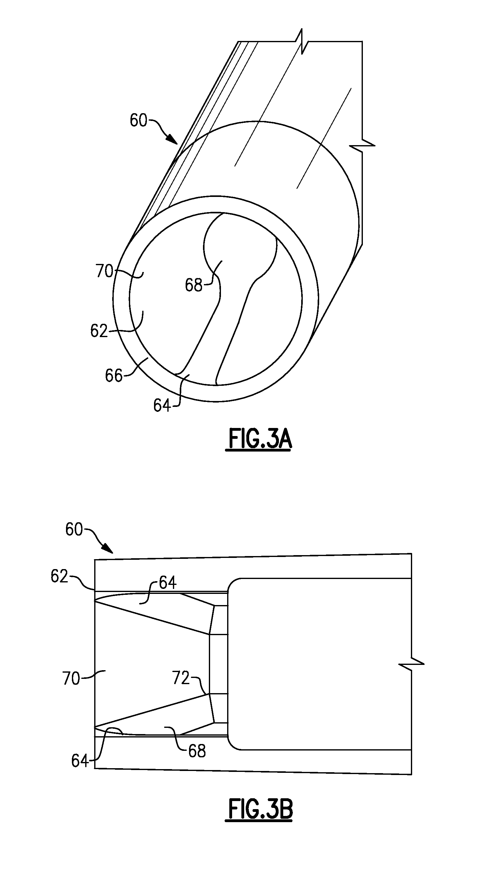
FIG. 3A shows a second embodiment.
FIG. 3B is a cross-sectional view through the second embodiment.
FIG. 4 shows a third embodiment.
FIG. 5 shows a fourth embodiment.
DETAILED DESCRIPTION
FIG. 1A shows an aircraft body 20 schematically. An air data probe 22 is mounted to the aircraft body 20. The air data probe 22 has a tap 24 in a pitot tube 21 at a forward end. The tap 24 samples a portion of air W as the aircraft moves through the air. The tapped air will move into an opening 28 in a passage 26, and to a pressure tap 30. Pressure tap 30 is shown communicating with a control 31. Control 31 translates the tapped pressure into an air speed of the aircraft body 20. In addition, a static pressure tap 32 is utilized and communicates to the control 31. A hole 33 provides a tap to communicate air to the static pressure tap 32. Since the air data probe 22 may be utilized in environments having ice, heater elements 36 are provided. An electric heater connection 38 communicates to the control 31 and provides electric power to the heater element 36.
As shown in FIG. 1B, the existing air data probe 22 has the tap 24 leading from an outermost end 42 inwardly to a throat 40. As shown, the air data probe 22 is at an angle that is relatively pronounced compared to the flight path. At such operation, a pronounced angle of attack, the air entering the tap 24 may have a recirculation region 44. There is also boundary layer separation. When this occurs, it becomes more difficult to obtain an acceptable total pressure.
FIG. 2A shows an air data probe 46 wherein the tap 47 extends from an outer end 48 inwardly toward a throat 50. A plurality of bleed holes 52 extend through a body of the air data probe 46 from an outlet 54 at an outer peripheral surface to an inlet 56 at an inner surface 57. Inner surface 57 of the air data probe 46 extends from the outer end 48 at an angle that decreases the cross-sectional area of an inner flow path as it moves inwardly until it reaches the throat 50. The bleed hole 52 has inlet 56 upstream of the throat 50.
FIG. 2B is a view showing a plurality of bleed holes 52. The quantity, size and location of the bleed holes 52 may be selected for specific operation in a particular environment.
FIG. 2C shows the operation of the air data probe 46. Air entering through the bleed holes 52 leaves the inner flow path, eliminating the recirculation and boundary layer separation illustrated in FIG. 1B. As shown, there is now uniform flow.
FIG. 3A shows an air data probe 60 wherein the tap 62 has a forward end 66 with a fluted slot with a circumferentially thin portion 64 leading into a circumferentially enlarged opening 68. Other areas 70 of the tap 62 do not have the slots 64/68.
As shown in FIG. 3B, there are slots 64/68 on opposed sides with intermediate generally cylindrical portions 70. Notably, the slots 64/68 end at the throat 72.
The slots 64/68 assist in bringing air in to reduce recirculation and boundary layer separation, similar to the FIG. 2A-2C embodiment.
Generically, the FIGS. 2A-2C and FIGS. 3A, 3B embodiments could be said to have removed material to assist in providing additional air pressure.
The FIGS. 2A-2C, and FIGS. 3A/3B embodiment could be said to have a pitot tube with a tap at a forward end, and defining an inner flow path. The inner flow path decreases in cross-sectional area until reaching a throat. The inner flow path has cross-sections which are generally cylindrical, and also has sections of removed material (bleed holes 52 or slots 64/68).
FIG. 4 shows yet another air data probe embodiment 74. Embodiment 74 could be seen as a "long nose" air data probe. A nose 76 is provided with a relatively small diameter d.sub.1. The diameter d.sub.1 extends through a long nose that is generally straight or slightly tapered across a distance d.sub.2. At an enlarged area 78, the diameter begins to increase to provide room for receiving a heater element 80. The enlarged area 78 is at a diameter d.sub.3. A bleed hole 82 may be incorporated much like the FIG. 2A-2C embodiments.
In embodiments, a relationship exists between the ratio of d.sub.3/d.sub.1 multiplied by a constant to d.sub.2. The d.sub.3 quantity is controlled by physical characteristics of the probe tube and the heater element 80. The d.sub.1 quantity is controlled by environmental conditions in which the probe is required to operate.
A ratio of d.sub.1 to d.sub.3 identifies how long d.sub.2 should be. Applicant has discovered a constant that is associated with the relationship of the three quantities. Thus, the following relationship preferably applies: (d.sub.1/d.sub.3)*1.26=d.sub.2
The 1.26 constant in this equation is what is determined for a standard pitot probe similar to the one shown in the Figures of this application. The three quantities will generally meet this relationship in a disclosed embodiment. The term "generally" as used in this context would mean +/1 five percent (5%) of 1.26.
The long length nose 76 combines the small diameter opening 75 to increase the operation of the air data probe 74.
FIG. 5 shows yet another air data probe 84. An optional bleed hole 88 is also shown.
An outer end of the probe 84 has a relatively flat outer surface 85 on a portion of its outer circumference and a bulged portion extending outwardly away from the flat surface and then merging inwardly such that the bulged portion provides an outer diameter portion spaced further from the flat portion, then do portions both rearwardly 87 and forwardly 89 of the bulged portion.
In addition, the air data probe 84 with bulged portion 86 provides a valuable test device. The bulged portion 86 may be rotated about an axis of the air data probe at multiple angles. Total pressure recovery may be checked at each and compared to others to determine low and high pressure points.
Although an embodiment of this invention has been disclosed, a worker of ordinary skill in this art would recognize that certain modifications would come within the scope of this invention. For that reason, the following claims should be studied to determine the true scope and content of this invention.
* * * * *
D00000
D00001
D00002
D00003
D00004
D00005
XML
uspto.report is an independent third-party trademark research tool that is not affiliated, endorsed, or sponsored by the United States Patent and Trademark Office (USPTO) or any other governmental organization. The information provided by uspto.report is based on publicly available data at the time of writing and is intended for informational purposes only.
While we strive to provide accurate and up-to-date information, we do not guarantee the accuracy, completeness, reliability, or suitability of the information displayed on this site. The use of this site is at your own risk. Any reliance you place on such information is therefore strictly at your own risk.
All official trademark data, including owner information, should be verified by visiting the official USPTO website at www.uspto.gov. This site is not intended to replace professional legal advice and should not be used as a substitute for consulting with a legal professional who is knowledgeable about trademark law.