User interface object manipulations in a user interface
Zambetti , et al.
U.S. patent number 10,275,117 [Application Number 14/913,350] was granted by the patent office on 2019-04-30 for user interface object manipulations in a user interface. This patent grant is currently assigned to Apple Inc.. The grantee listed for this patent is Apple Inc.. Invention is credited to Gary Ian Butcher, Imran Chaudhri, Jonathan R. Dascola, Alan C. Dye, Christopher Patrick Foss, Aurelio Guzman, Jonathan P. Ive, Chanaka G. Karunamuni, Duncan Robert Kerr, Stephen O. Lemay, Natalia Maric, Christopher Wilson, Eric Lance Wilson, Lawrence Y. Yang, Nicholas Zambetti.


View All Diagrams
| United States Patent | 10,275,117 |
| Zambetti , et al. | April 30, 2019 |
| **Please see images for: ( Certificate of Correction ) ** |
User interface object manipulations in a user interface
Abstract
Systems and processes for manipulating a graphical user interface are disclosed. One process can include receiving user input through a crown to rotate a virtual object. The process includes selecting a surface of the object from among the multiple surfaces of the object in response to determining that the crown rotation exceeded a speed threshold.
| Inventors: | Zambetti; Nicholas (San Francisco, CA), Chaudhri; Imran (San Francisco, CA), Dascola; Jonathan R. (San Francisco, CA), Dye; Alan C. (San Francisco, CA), Foss; Christopher Patrick (San Francisco, CA), Guzman; Aurelio (San Jose, CA), Karunamuni; Chanaka G. (San Jose, CA), Kerr; Duncan Robert (San Francisco, CA), Lemay; Stephen O. (Palo Alto, CA), Maric; Natalia (San Francisco, CA), Wilson; Christopher (San Francisco, CA), Wilson; Eric Lance (San Jose, CA), Yang; Lawrence Y. (San Francisco, CA), Butcher; Gary Ian (San Jose, CA), Ive; Jonathan P. (San Francisco, CA) | ||||||||||
|---|---|---|---|---|---|---|---|---|---|---|---|
| Applicant: |
|
||||||||||
| Assignee: | Apple Inc. (Cupertino,
CA) |
||||||||||
| Family ID: | 56566794 | ||||||||||
| Appl. No.: | 14/913,350 | ||||||||||
| Filed: | September 3, 2014 | ||||||||||
| PCT Filed: | September 03, 2014 | ||||||||||
| PCT No.: | PCT/US2014/053958 | ||||||||||
| 371(c)(1),(2),(4) Date: | February 19, 2016 | ||||||||||
| PCT Pub. No.: | WO2015/034966 | ||||||||||
| PCT Pub. Date: | March 12, 2015 |
Prior Publication Data
| Document Identifier | Publication Date | |
|---|---|---|
| US 20160231883 A1 | Aug 11, 2016 | |
Related U.S. Patent Documents
| Application Number | Filing Date | Patent Number | Issue Date | ||
|---|---|---|---|---|---|
| 14476657 | Sep 3, 2014 | ||||
| 61873359 | Sep 3, 2013 | ||||
| 61959851 | Sep 3, 2013 | ||||
| 61873360 | Sep 3, 2013 | ||||
| 61873356 | Sep 3, 2013 | ||||
| Current U.S. Class: | 1/1 |
| Current CPC Class: | G06F 3/04845 (20130101); G06T 13/80 (20130101); G06F 3/0481 (20130101); G06F 3/0362 (20130101); G06F 1/163 (20130101); G06F 1/169 (20130101); G06F 3/0482 (20130101); G06F 2203/04802 (20130101) |
| Current International Class: | G06F 3/0482 (20130101); G06F 3/0362 (20130101); G06T 13/80 (20110101); G06F 1/16 (20060101); G06F 3/0484 (20130101); G06F 3/0481 (20130101) |
References Cited [Referenced By]
U.S. Patent Documents
| 4395134 | July 1983 | Luce |
| 5088070 | February 1992 | Shiff |
| 5313229 | May 1994 | Gilligan et al. |
| 5477508 | December 1995 | Will |
| 5519393 | May 1996 | Brandestini |
| 5528260 | June 1996 | Kent |
| 5691747 | November 1997 | Amano |
| 5739775 | April 1998 | Brandestini |
| 5825353 | October 1998 | Will |
| 5852413 | December 1998 | Bacchi et al. |
| 5874961 | February 1999 | Bates et al. |
| 5903229 | May 1999 | Kishi |
| 5940521 | August 1999 | East et al. |
| 5960366 | September 1999 | Duwaer |
| 5982710 | November 1999 | Rawat et al. |
| 6081256 | June 2000 | Herget |
| 6128006 | October 2000 | Rosenberg |
| 6157381 | December 2000 | Bates et al. |
| 6161957 | December 2000 | Guanter |
| 6192258 | February 2001 | Kamada et al. |
| 6203190 | March 2001 | Stotz |
| 6266098 | July 2001 | Cove |
| 6297795 | October 2001 | Kato et al. |
| 6300939 | October 2001 | Decker et al. |
| 6305234 | October 2001 | Thies et al. |
| 6323846 | November 2001 | Westerman et al. |
| 6339438 | January 2002 | Bates et al. |
| 6396482 | May 2002 | Griffin et al. |
| 6477117 | November 2002 | Narayanaswami et al. |
| 6525997 | February 2003 | Narayanaswami |
| 6535461 | March 2003 | Karhu |
| 6556222 | April 2003 | Narayanaswami |
| 6570557 | May 2003 | Westerman et al. |
| 6636197 | October 2003 | Goldenberg et al. |
| 6647338 | November 2003 | Hamberger et al. |
| 6661438 | December 2003 | Shiraishi |
| 6677932 | January 2004 | Westerman |
| 6700564 | March 2004 | McLoone et al. |
| 6720860 | April 2004 | Narayanaswami |
| 6788220 | September 2004 | Netzer et al. |
| 6809724 | October 2004 | Shiraishi |
| 6842169 | January 2005 | Griffin et al. |
| 6967642 | November 2005 | SanGiovanni |
| 6967903 | November 2005 | Guanter |
| 7046230 | May 2006 | Zadesky et al. |
| 7058904 | June 2006 | Khan |
| 7075513 | July 2006 | Silfverberg et al. |
| 7081905 | July 2006 | Raghunath |
| 7116317 | October 2006 | Gregorio et al. |
| 7130664 | October 2006 | Williams |
| 7143355 | November 2006 | Yamaguchi et al. |
| 7146005 | December 2006 | Anft et al. |
| 7168047 | January 2007 | Huppi |
| 7227963 | June 2007 | Yamada et al. |
| 7256770 | August 2007 | Hinckley et al. |
| 7272077 | September 2007 | Nobs |
| 7286063 | October 2007 | Gauthey et al. |
| 7286119 | October 2007 | Yamaguchi et al. |
| 7317449 | January 2008 | Robbins et al. |
| 7333084 | February 2008 | Griffin |
| 7463239 | December 2008 | Ledbetter et al. |
| 7469386 | December 2008 | Bear et al. |
| 7477890 | January 2009 | Narayanaswami |
| 7489303 | February 2009 | Pryor |
| 7499040 | March 2009 | Zadesky et al. |
| 7506269 | March 2009 | Lang |
| 7519468 | April 2009 | Orr et al. |
| 7614008 | November 2009 | Ording |
| 7633076 | December 2009 | Huppi et al. |
| 7653883 | January 2010 | Hotelling et al. |
| 7657849 | February 2010 | Chaudhri et al. |
| 7663607 | February 2010 | Hotelling et al. |
| 7794138 | September 2010 | Hilfiker |
| 7844914 | November 2010 | Andre et al. |
| 7844915 | November 2010 | Platzer et al. |
| 7856255 | December 2010 | Tsuchiya et al. |
| 7957762 | June 2011 | Herz et al. |
| 8001488 | August 2011 | Lam |
| 8006002 | August 2011 | Kalayjian et al. |
| 8009144 | August 2011 | Yajima |
| 8050997 | November 2011 | Nosek et al. |
| 8140996 | March 2012 | Tomkins |
| 8239784 | August 2012 | Hotelling et al. |
| 8279180 | October 2012 | Hotelling et al. |
| 8307306 | November 2012 | Komatsu |
| 8311727 | November 2012 | Eckstein et al. |
| 8365090 | January 2013 | Ording |
| 8381135 | February 2013 | Hotelling et al. |
| 8479122 | July 2013 | Hotelling et al. |
| 8566722 | October 2013 | Gordon |
| 8627236 | January 2014 | Jung |
| 8686944 | April 2014 | Charlton et al. |
| 8799816 | August 2014 | Wells et al. |
| 8824245 | September 2014 | Lau et al. |
| 9007057 | April 2015 | Villaret |
| 9007302 | April 2015 | Bandt-Horn |
| 9007323 | April 2015 | Araki |
| 9052814 | June 2015 | Ording |
| 9104705 | August 2015 | Fujinaga |
| 9395867 | July 2016 | Griffin et al. |
| 9395905 | July 2016 | Wherry |
| 9442649 | September 2016 | Davis et al. |
| 9823828 | November 2017 | Zambetti |
| 2001/0004337 | June 2001 | Paratte |
| 2001/0011991 | August 2001 | Wang et al. |
| 2002/0015024 | February 2002 | Westerman et al. |
| 2002/0019296 | February 2002 | Freeman et al. |
| 2002/0027547 | March 2002 | Kamijo et al. |
| 2002/0030668 | March 2002 | Hoshino et al. |
| 2002/0036623 | March 2002 | Kano |
| 2002/0063684 | May 2002 | Tran |
| 2002/0101458 | August 2002 | SanGiovanni |
| 2002/0118169 | August 2002 | Hinckley et al. |
| 2002/0126099 | September 2002 | Engholm |
| 2002/0154150 | October 2002 | Ogaki et al. |
| 2002/0154175 | October 2002 | Abello et al. |
| 2002/0171689 | November 2002 | Fox et al. |
| 2002/0186621 | December 2002 | Lai |
| 2003/0025673 | February 2003 | Ledbetter et al. |
| 2003/0076301 | April 2003 | Tsuk et al. |
| 2003/0103044 | June 2003 | Sunda |
| 2003/0112279 | June 2003 | Irimajiri |
| 2003/0115384 | June 2003 | Sonehara et al. |
| 2003/0123329 | July 2003 | Guanter et al. |
| 2003/0189598 | October 2003 | Lipstein et al. |
| 2003/0210286 | November 2003 | Gerpheide et al. |
| 2004/0013042 | January 2004 | Farine |
| 2004/0047244 | March 2004 | Iino et al. |
| 2004/0085328 | May 2004 | Maruyama |
| 2004/0100479 | May 2004 | Nakano et al. |
| 2004/0113819 | June 2004 | Gauthey et al. |
| 2004/0130580 | July 2004 | Howard et al. |
| 2004/0145595 | July 2004 | Bennett |
| 2004/0150621 | August 2004 | Bohn |
| 2004/0155907 | August 2004 | Yamaguchi et al. |
| 2004/0218472 | November 2004 | Narayanaswami et al. |
| 2004/0225613 | November 2004 | Narayanaswami et al. |
| 2004/0239692 | December 2004 | Balle |
| 2005/0007884 | January 2005 | Lorenzato |
| 2005/0081164 | April 2005 | Hama et al. |
| 2005/0097466 | May 2005 | Levi Montalcini |
| 2005/0168566 | August 2005 | Tada et al. |
| 2005/0183012 | August 2005 | Petro |
| 2005/0190059 | September 2005 | Wehrenberg |
| 2005/0195216 | September 2005 | Kramer et al. |
| 2005/0209051 | September 2005 | Santomassimo et al. |
| 2005/0215848 | September 2005 | Lorenzato et al. |
| 2005/0259077 | November 2005 | Adams et al. |
| 2006/0007129 | January 2006 | Pletikosa et al. |
| 2006/0017692 | January 2006 | Wehrenberg et al. |
| 2006/0020904 | January 2006 | Aaltonen et al. |
| 2006/0026535 | February 2006 | Hotelling et al. |
| 2006/0026536 | February 2006 | Hotelling et al. |
| 2006/0028444 | February 2006 | Hinckley et al. |
| 2006/0033724 | February 2006 | Chaudhri et al. |
| 2006/0092177 | May 2006 | Blasko |
| 2006/0112350 | May 2006 | Kato |
| 2006/0152480 | July 2006 | Senn |
| 2006/0181506 | August 2006 | Fyke |
| 2006/0197753 | September 2006 | Hotelling |
| 2006/0255683 | November 2006 | Suzuki |
| 2006/0268019 | November 2006 | Wang et al. |
| 2006/0268020 | November 2006 | Han |
| 2007/0063995 | March 2007 | Bailey et al. |
| 2007/0070090 | March 2007 | Debettencourt et al. |
| 2007/0085841 | April 2007 | Tsuk et al. |
| 2007/0097151 | May 2007 | Rosenberg |
| 2007/0120819 | May 2007 | Young et al. |
| 2007/0209017 | September 2007 | Gupta et al. |
| 2007/0211042 | September 2007 | Kim |
| 2007/0226646 | September 2007 | Nagiyama et al. |
| 2007/0229458 | October 2007 | Moon |
| 2007/0236475 | October 2007 | Wherry |
| 2007/0242569 | October 2007 | Inoue et al. |
| 2007/0247435 | October 2007 | Benko et al. |
| 2007/0279401 | December 2007 | Ramstein |
| 2007/0290045 | December 2007 | Cisar |
| 2007/0296711 | December 2007 | Yee |
| 2008/0001915 | January 2008 | Pihlaja et al. |
| 2008/0004084 | January 2008 | Park |
| 2008/0020810 | January 2008 | Park |
| 2008/0043028 | February 2008 | Tanaka |
| 2008/0123473 | May 2008 | Ozawa et al. |
| 2008/0148177 | June 2008 | Lang et al. |
| 2008/0155461 | June 2008 | Ozaki |
| 2008/0155475 | June 2008 | Duhig |
| 2008/0158149 | July 2008 | Levin |
| 2008/0165140 | July 2008 | Christie et al. |
| 2008/0168382 | July 2008 | Louch et al. |
| 2008/0168404 | July 2008 | Ording |
| 2008/0204478 | August 2008 | Hung |
| 2008/0257701 | October 2008 | Wlotzka |
| 2008/0288880 | November 2008 | Reponen et al. |
| 2008/0320391 | December 2008 | Lemay et al. |
| 2009/0015550 | January 2009 | Koski |
| 2009/0050465 | February 2009 | Asada et al. |
| 2009/0051649 | February 2009 | Rondel |
| 2009/0059730 | March 2009 | Lyons et al. |
| 2009/0079698 | March 2009 | Takashima et al. |
| 2009/0100373 | April 2009 | Pixley |
| 2009/0109069 | April 2009 | Takasaki et al. |
| 2009/0143117 | June 2009 | Shin et al. |
| 2009/0152452 | June 2009 | Lee et al. |
| 2009/0156255 | June 2009 | Shin et al. |
| 2009/0196124 | August 2009 | Mooring et al. |
| 2009/0199130 | August 2009 | Tsern et al. |
| 2009/0204920 | August 2009 | Beverley |
| 2009/0325563 | December 2009 | Horodezky et al. |
| 2010/0029327 | February 2010 | Jee |
| 2010/0058223 | March 2010 | Price |
| 2010/0058240 | March 2010 | Buil et al. |
| 2010/0093400 | April 2010 | Ju et al. |
| 2010/0110044 | May 2010 | Englund |
| 2010/0128570 | May 2010 | Smith et al. |
| 2010/0169097 | July 2010 | Nachman et al. |
| 2010/0187074 | July 2010 | Manni |
| 2010/0220562 | September 2010 | Hozumi et al. |
| 2010/0248778 | September 2010 | Biswas |
| 2010/0259481 | October 2010 | Oh et al. |
| 2010/0269038 | October 2010 | Tsuda |
| 2010/0271340 | October 2010 | Nagashima et al. |
| 2010/0271342 | October 2010 | Nagashima et al. |
| 2010/0271343 | October 2010 | Nagashima et al. |
| 2010/0277126 | November 2010 | Naeimi et al. |
| 2010/0315417 | December 2010 | Cho et al. |
| 2010/0325575 | December 2010 | Platzer et al. |
| 2010/0331145 | December 2010 | Lakovic et al. |
| 2011/0006980 | January 2011 | Taniguchi et al. |
| 2011/0014956 | January 2011 | Lee |
| 2011/0025311 | February 2011 | Chauvin et al. |
| 2011/0057886 | March 2011 | Ng et al. |
| 2011/0099509 | April 2011 | Horagai |
| 2011/0131494 | June 2011 | Ono et al. |
| 2011/0131531 | June 2011 | Russell et al. |
| 2011/0157046 | June 2011 | Lee et al. |
| 2011/0164042 | July 2011 | Chaudhri |
| 2011/0167262 | July 2011 | Ross et al. |
| 2011/0187355 | August 2011 | Dixon et al. |
| 2011/0224967 | September 2011 | Van |
| 2011/0252357 | October 2011 | Chaudhri |
| 2011/0296312 | December 2011 | Boyer et al. |
| 2011/0298830 | December 2011 | Lam |
| 2012/0026198 | February 2012 | Maesaka |
| 2012/0044267 | February 2012 | Fino et al. |
| 2012/0066638 | March 2012 | Ohri et al. |
| 2012/0092383 | April 2012 | Hysek |
| 2012/0099406 | April 2012 | Lau et al. |
| 2012/0105484 | May 2012 | Cui |
| 2012/0131504 | May 2012 | Fadell et al. |
| 2012/0174005 | July 2012 | Deutsch et al. |
| 2012/0186951 | July 2012 | Wu et al. |
| 2012/0278725 | November 2012 | Gordon |
| 2012/0324390 | December 2012 | Tao et al. |
| 2013/0142016 | June 2013 | Pozzo Di Borgo |
| 2013/0145292 | June 2013 | Cohen et al. |
| 2013/0169579 | July 2013 | Havnor |
| 2013/0176020 | July 2013 | Chauvin et al. |
| 2013/0205939 | August 2013 | Meerovitsch |
| 2013/0218517 | August 2013 | Ausserlechner |
| 2013/0258819 | October 2013 | Hoover |
| 2013/0303087 | November 2013 | Hauser et al. |
| 2014/0028688 | January 2014 | Houjou et al. |
| 2014/0132640 | May 2014 | Sharma et al. |
| 2014/0137020 | May 2014 | Sharma et al. |
| 2014/0143678 | May 2014 | Mistry et al. |
| 2014/0253487 | September 2014 | Bezinge et al. |
| 2014/0258935 | September 2014 | Nishida et al. |
| 2014/0260776 | September 2014 | Burleson |
| 2014/0282214 | September 2014 | Shirzadi et al. |
| 2014/0306989 | October 2014 | Doubleday et al. |
| 2014/0347289 | November 2014 | Suh et al. |
| 2015/0277559 | October 2015 | Vescovi et al. |
| 2015/0370529 | December 2015 | Zambetti et al. |
| 2015/0378447 | December 2015 | Nagano et al. |
| 2016/0034133 | February 2016 | Wilson et al. |
| 2016/0034166 | February 2016 | Wilson et al. |
| 2016/0034167 | February 2016 | Wilson et al. |
| 2016/0062466 | March 2016 | Moussette et al. |
| 2016/0063828 | March 2016 | Moussette et al. |
| 2016/0098016 | April 2016 | Ely et al. |
| 2016/0170598 | June 2016 | Zambetti |
| 2016/0170624 | June 2016 | Zambetti et al. |
| 2016/0170625 | June 2016 | Zambetti et al. |
| 2016/0202866 | July 2016 | Zambetti et al. |
| 2016/0209939 | July 2016 | Zambetti et al. |
| 2016/0259535 | September 2016 | Fleizach et al. |
| 2016/0269540 | September 2016 | Butcher et al. |
| 2016/0327911 | November 2016 | Eim et al. |
| 2017/0315716 | November 2017 | Zambetti et al. |
| 2018/0074690 | March 2018 | Zambetti et al. |
| 1330310 | Jan 2002 | CN | |||
| 1398366 | Feb 2003 | CN | |||
| 1757011 | Apr 2006 | CN | |||
| 101431545 | May 2009 | CN | |||
| 101446802 | Jun 2009 | CN | |||
| 101241407 | Jul 2011 | CN | |||
| 102402328 | Apr 2012 | CN | |||
| 101034328 | Feb 2013 | CN | |||
| 103460164 | Dec 2013 | CN | |||
| 1052566 | Nov 2000 | EP | |||
| 1168149 | Jan 2002 | EP | |||
| 1850213 | Oct 2007 | EP | |||
| 2207084 | Jul 2010 | EP | |||
| 2302492 | Mar 2011 | EP | |||
| 2385451 | Nov 2011 | EP | |||
| 2000-305760 | Nov 2000 | JP | |||
| 2001-202178 | Jul 2001 | JP | |||
| 2002-288690 | Oct 2002 | JP | |||
| 20003-248544 | Sep 2003 | JP | |||
| 2003-330586 | Nov 2003 | JP | |||
| 2003-330856 | Nov 2003 | JP | |||
| 2004-184396 | Jul 2004 | JP | |||
| 2004-259063 | Sep 2004 | JP | |||
| 2006-11690 | Jan 2006 | JP | |||
| 2008-157974 | Jul 2008 | JP | |||
| 2008-539513 | Nov 2008 | JP | |||
| 2009-59382 | Mar 2009 | JP | |||
| 2009-510404 | Mar 2009 | JP | |||
| 2009-128296 | Jun 2009 | JP | |||
| 2009-294526 | Dec 2009 | JP | |||
| 2011-8540 | Jan 2011 | JP | |||
| 2011-90640 | May 2011 | JP | |||
| 2011-96043 | May 2011 | JP | |||
| 2011-530738 | Dec 2011 | JP | |||
| 2013-114844 | Jun 2013 | JP | |||
| 2013-122738 | Jun 2013 | JP | |||
| 2014-42164 | Mar 2014 | JP | |||
| 10-0630154 | Sep 2006 | KR | |||
| 10-2011-0093090 | Aug 2011 | KR | |||
| 10-2011-0114294 | Oct 2011 | KR | |||
| 10-2012-0079707 | Jul 2012 | KR | |||
| 10-2013-0027017 | Mar 2013 | KR | |||
| D122820 | May 2008 | TW | |||
| 1996/19872 | Jun 1996 | WO | |||
| 0169369 | Sep 2001 | WO | |||
| 2006/037545 | Apr 2006 | WO | |||
| 2009/026508 | Feb 2009 | WO | |||
| 2010/024969 | Mar 2010 | WO | |||
| 2010/150768 | Dec 2010 | WO | |||
| 2012080020 | Jun 2012 | WO | |||
| 2013/114844 | Aug 2013 | WO | |||
| 2013/169849 | Nov 2013 | WO | |||
| 2014105276 | Jul 2014 | WO | |||
Other References
|
Office Action received for Taiwanese Patent Application No. 103130520, dated Oct. 1, 2015, 58 pages (22 pages of English translation and 36 pages of Official copy). cited by applicant . Office Action received for Taiwan Patent Application No. 103130519.0, dated Mar. 25, 2016, 14 pages( 6 pages of English Translation and 8 pages of Official Copy). cited by applicant . International Preliminary Report on Patentability received for PCT Patent Application No. PCT/US2014/053951, dated Mar. 17, 2016, 9 pages. cited by applicant . International Search Report and Written Opinion received for PCT Patent Application No. PCT/US2014/053951, dated Dec. 8, 2014, 11 pages. cited by applicant . International Search Report and Written Opinion received for PCT Patent Application No. PCT/US2014/053958, dated Feb. 19, 2015, 10 pages. cited by applicant . International Preliminary Report on Patentability received for PCT Patent Application No. PCT/US2014/053958, dated Mar. 17, 2016, 8 pages. cited by applicant . Invitation to Pay Additional Fees received for PCT Application No. PCT/US2014/053961, dated Aug. 3, 2015, 6 pages. cited by applicant . Kamijo, Noboru, "Next Generation Mobile System--WatchPad1.5", Available at <http://researcher.ibm.com/researcher/view_group_subpage.php?id=5617&g- t;, retrieved on Jul. 4, 2015, 2 pages. cited by applicant . NDTV, "Sony SmartWatch 2 Launched in India for Rs. 14,990", available at <http://gadgets.ndtv.com/others/news/sony-smartwatch-2-launched-in-ind- ia-for-rs-14990-420319>, Sep. 18, 2013, 4 pages. cited by applicant . Invitation to Pay Additional Fees received for PCT Patent Application No. PCT/US2016/019637, dated Jun. 1, 2016, 6 pages. cited by applicant . Notice of Allowance received for Taiwanese Patent Application No. 103130518, dated May 19, 2016, 2 pages. (See Communication under 37 CFR .sctn. 1.98(a) (3)). cited by applicant . Office Action and Search Report received for Danish Patent Application No. PA 201670118, dated Jul. 1, 2016, 7 pages. cited by applicant . Office Action received for Taiwanese Patent Application No. 103130520, dated May 23, 2016, 38 pages (15 pages of English Translation and 23 pages of Official Copy). cited by applicant . International Preliminary Report on Patentability received for PCT Patent Application No. PCT/US2014/053961, dated Jul. 21, 2016, 24 pages. cited by applicant . Written Opinion received for PCT Patent Application No. PCT/US2014/053961, dated Jul. 11, 2016, 22 pages. cited by applicant . International Search Report and Written Opinion received for PCT Patent Application No. PCT/US2016/019637, dated Aug. 18, 2016, 18 pages. cited by applicant . International Search Report received for PCT Patent Application No. PCT/US2014/053961, dated Jul. 11, 2016, 10 pages. cited by applicant . Advisory Action received for U.S. Appl. No. 15/049,064, dated May 10, 2017, 3 Pages. cited by applicant . Final Office Action received for U.S. Appl. No. 15/049,058, dated May 8 2017, 21 pages. cited by applicant . Notice of Allowance received for Australian Patent Application No. 2014315325, dated Apr. 19, 2017, 3 Pages. cited by applicant . Office Action received for Japanese Patent Application No. 2016-537945, dated Apr. 7, 2017, 6 pages (3 pages of English Translation and 3 pages of Official Copy). cited by applicant . Office Action received for Taiwanese Patent Application No. 103130520, dated Apr. 17, 2017, 8 pages (3 pages of English Translation and 5 pages of Official Copy). cited by applicant . "The Interview With a Key Person. IBM and Citizen met and Applied Linux to a Watch", ASCII Corporation, vol. 25, No. 12, Consecutive vol. 294, Dec. 1, 2001, pp. 137-143. cited by applicant . Final Office Action recieved for U.S. Appl. No. 15/049,049, dated May 23, 2017, 23 pages. cited by applicant . Wikipedia, "Rotary encoder", <https://zh.wikipedia.org/wiki/%E6%97%8B%E8%BD%89%E7%B7%A8%E7%A2%BC%E5- %99%A8>, Retrieved on May 17, 2017, 17 pages (10 pages of English Translation and 7 pages of Official Copy). cited by applicant . Notice of Allowance received for U.S. Appl. No. 15/049,064, dated Jul. 18, 2017, 24 pages. cited by applicant . Office Action received for Australian Patent Application No. 2014315234, dated Jul. 12, 2017, 4 pages. cited by applicant . Office Action received for European Patent Application No. 14772002.3, dated Jul. 4, 2017, 8 pages. cited by applicant . Office Action received for Japanese Patent Application No. 2016-537948, dated Jun. 9, 2017, 10 pages (5 pages of English Translation and 5 pages of Official Copy). cited by applicant . Office Action received for Chinese Patent Application No. 201480060082.7, dated Jan. 26, 2018, 15 pages (4 pages of English translation and 11 pages of Official Copy). cited by applicant . Non-Final Office Action received for U.S. Appl. No. 14/913,345, dated Apr. 5, 2018, 15 pages. cited by applicant . Brinkmann, Martin, "How to Zoom in Firefox", Ghacks, Available at <https://web.archive.org/web/20130804034728/https://www.ghacks.net/200- 9/02/23/how-to-zoom-in-firefox/>, Feb. 23, 2009, 11 pages. cited by applicant . Non-Final Office Action received for U.S. Appl. No. 15/049,049 dated Dec. 15, 2017, 23 pages. cited by applicant . Office Action received for European Patent Application No. 14771688.0, dated Nov. 30, 2017, 15 pages. cited by applicant . Office Action received for Korean Patent Application No. 10-2016-7008488, dated Nov. 27, 2017, 6 pages (3 page of English Translation and 3 pages of Official Copy). cited by applicant . Office Action received for Korean Patent Application No. 10-2016-7008474, dated Nov. 27, 2017, 6 pages (2 page of English Translation and 4 pages of Official Copy). cited by applicant . Office Action received for Korean Patent Application No. 10-2016-7008682, dated Nov. 27, 2017, 7 pages (3 page of English Translation and 4 pages of Official Copy). cited by applicant . Non-Final Office Action received for U.S. Appl. No. 15/049,058, dated Feb. 20, 2018, 21 pages. cited by applicant . Notice of Allowance Action received for U.S. Appl. No. 14/841,656, dated Feb. 12, 2018, 9 pages. cited by applicant . Office Action received for Japanese Patent Application No. 2016-537945, dated Jan. 9, 2018, 5 pages (2 page of English Translation and 3 pages of Official copy). cited by applicant . Office Action received for Korean Patent Application No. 10-2016-7008682, dated Feb. 8, 2018, 7 pages (3 pages of English Translation and 4 pages of Official Copy). cited by applicant . Decision to Grant received for Danish Patent Application No. PA201770181, dated Mar. 7, 2018, 2 pages. cited by applicant . Notice of Allowance received for U.S. Appl. No. 14/841,656, dated Mar. 5, 2018, 3 pages. cited by applicant . Office Action received for Australian Patent Application No. 2018200998, dated Mar. 9, 2018, 5 pages. cited by applicant . Office Action received for Korean Patent Application No. 10-2016-7008488, dated Feb. 8, 2018, 8 pages (4 page of English Translation and 4 pages of Official Copy). cited by applicant . Office Action received for Korean Patent Application No. 10-2018-7002695, dated Feb. 27, 2018, 12 pages (5 pages of English Translation and 7 pages of Official Copy). cited by applicant . Office Action received for Taiwanese Patent Application No. 103130520, dated Jan. 23, 2018, 05 pages (2 pages of English Translation and 3 pages of Offcial Copy). cited by applicant . IBM, "watchpad 1.5", Online Available at <web.archive.org/web/20011205071448/http://www.trl.ibm.com/projects/ng- m/index_e.htm>, 2 pages. cited by applicant . Raghunath et al., "User Interfaces for Applications on a Wrist Watch", Journal of Personal and Ubiquitous Computing, vol. 6, No. 1, pp. 17-30. cited by applicant . "Watchpad 1.5 demo", YouTube.com, Online Available at <https://www.youtube.com/watch?v=7xjvVbeUn80>, Uploaded on Jun. 20, 2010, 2 pages. cited by applicant . Non-Final Office Action received for U.S. Appl. No. 15/049,058, dated Nov. 16, 2016, 19 pages. cited by applicant . Non-Final Office Action received for U.S. Appl. No. 15/049,064, dated Oct. 27, 2016, 15 pages. cited by applicant . Non-Final Office Action received for U.S. Appl. 15/049,049, dated Nov. 9, 2016, 13 pages. cited by applicant . Notice of Allowance received for Taiwanese Patent Application No. 103130519, dated Oct. 27, 2016, 3 pages (Official Copy only) (see attached 37 CFR .sctn. 1.98(a) (3)). cited by applicant . Office Action received for Australian Patent Application No. 2014315234, dated Nov. 2, 2016, 3 pages. cited by applicant . Office Action received for Australian Patent Application No. 2014315319, dated Oct. 17, 2016, 3 pages. cited by applicant . Office Action received for Australian Patent Application No. 2014315325, dated Nov. 3, 2016, 3 pages. cited by applicant . Office Action received for Taiwanese Patent Application No. 103130520, dated Sep. 29, 2016, 39 pages (16 pages of English Translation and 23 pages of Official Copy). cited by applicant . Final Office Action received for U.S. Appl. No. 15/049,064, dated Feb. 27, 2017, 13 pages. cited by applicant . Office Action received for Danish Patent Application No. PA201670113, dated Oct. 25, 2016, 3 pages. cited by applicant . Notice of Allowance received for Danish Patent Application No. PA201670118, dated Mar. 30, 2017, 2 pages. cited by applicant . Office Action received for Japanese Patent Application No. 2016-537947, dated Feb. 24, 2017, 6 pages (3 pages of English Tramsiation and 3 pages of Official Copy). cited by applicant . Office Action received for Australian Patent Application No. 2014315234, dated Apr. 19, 2017, 4 pages. cited by applicant . Notice of Allowance received for Japanese Patent Application No. 2016-537947, dated Jun. 5, 2017, 3 pages (Official Copy only) (see attached 37 CFR .sctn. 1.98(a) (3)). cited by applicant . Office Action received for Danish Patent Application No. PA201770181, dated Jun. 13, 2017, 6 pages. cited by applicant . Office Action received for European Patent Application No. 14772494.2, dated Jun. 20, 2017, 7 pages. cited by applicant . Advisory Action received for U.S. Appl. No. 15/049,058, dated Oct. 18, 2017, 3 pages. cited by applicant . International Preliminary Report on Patentability received for PCT Patent Application No. PCT/US2016/019637, dated Sep. 21, 2017, 12 pages. cited by applicant . Notice of Allowance received for Australian Patent Application No. 2014315319, dated Oct. 12, 2017, 3 pages. cited by applicant . Office Action received for Danish Patent Application No. PA201770181, dated Jan. 3, 2018, 2 pages. cited by applicant . Office Action received for Korean Patent Appiication No. 10-2016-7008474, dated Dec. 28, 2016, 10 pages (4 pages of Eglish Translation and 6 pages of Official Copy). cited by applicant . Office Action received for Korean Patent Application No. 10-2016-7008488, dated Jan. 12, 2017, 14 pages (6 pages of English Translation 8 pages of Official Copy). cited by applicant . Office Action received for Karean Patent Applicaticn No. 10-2016-7008682, dated Dec. 30, 2016, 11 pages (4 pages of English Translation 7 pages of Official Copy). cited by applicant . Office Action received for Danish Patent Application No. PA201670118, dated Feb. 2, 2017, 2 pages. cited by applicant . Non-Final Office Action received for U.S. Appl. No. 14/841,656, dated Jul. 26, 2017, 20 pages. cited by applicant . Office Action received for Australian Patent Application No. 2014 15319, dated Aug. 3, 2017, 3 pages. cited by applicant . Final Office Action received for U.S. Appl. No. 15/049,058, dated Aug. 8, 2018, 23 pages. cited by applicant . Notice of Allowance received for Japanese Patent Application No. 2016-537945, dated Aug. 3, 2018, 4 pages (1 page of English translation and 3 pages of Official copy). cited by applicant . Office Action received for Korean Patent Application No. 10-2016-7008474, dated Aug. 6, 2018, 10 pages (5 pages of English Translation and 5 pages of Official Copy). cited by applicant . Corrected Notice of Allowance received for U.S. Appl. No. 14/841,656, dated Apr. 11, 2018, 2 pages. cited by applicant . Office Action received for Chinese Patent Application No. 201480059543.9, dated Jan. 26, 2018, 17 pages (4 pages of English Translation and 13 pages of Official Copy). cited by applicant . Office Action received for European Patent Application No. 14771688.0, dated May 31, 2018, 6 pages. cited by applicant . Office Action received for Korean Patent Application No. 10-2016-7008474, dated May 15, 2018, 7 pages (3 pages of English Translation and 4 pages of Official Copy). cited by applicant . Office Action received for Chinese Patent Application No. 201480060082.7, dated Sep. 25, 2018, 6 pages (3 pages of English Translation and 3 pages of Official copy). cited by applicant . Office Action received for European Patent Application No. 14772494.2, dated Oct. 2, 2018, 9 pages. cited by applicant . Office Action received for Japanese Patent Application No. 2016-537948, dated Sep. 3, 2018, 4 pages (2 pages of English Translation and 2 pages of Official copy). cited by applicant . Office Action received for Korean Patent Application No. 10-2017-7024506, dated Sep. 28, 2018, 11 pages (4 pages of English Translation and 7 pages of Official Copy). cited by applicant . Office Action received for Chinese Patent Application No. 201480059543.9, dated Sep. 19, 2018, 18 pages (5 pages of English Translation and 13 pages of Official Copy). cited by applicant . Final Office Action received for U.S. Appl. No. 15/049,049 dated Jul. 12, 2018, 24 pages. cited by applicant . Office Action received for Korean Patent Application No. 10-2018-7002695, dated Jun. 19, 2018, 8 pages (4 pages of English Translation and 4 pages of Official Copy). cited by applicant . Office Action received for Australian Patent Application No. 2016229407, dated Aug. 15, 2018, 4 pages. cited by applicant . Office Action received for Korean Patent Application No. 10-2018-7013265, dated Aug. 10, 2018, 12 pages (5 pages of English Translation and 7 pages of Official copy). cited by applicant . Office Action received for Australian Patent Application No. 2017254897, dated Aug. 29, 2018, 4 pages. cited by applicant . Office Action received for Japanese Patent Application No. 2017-545561, dated Aug. 6, 2018, 8 pages (4 pages of English Translation and 4 pages of Official copy). cited by applicant . Corrected Notice of Allowance received for U.S. Appl. No. 14/841,656, dated May 7, 2018, 14 pages. cited by applicant . Notice of Allowance received for Taiwanese Patent Application No. 103130520, dated Apr. 27, 2018, 4 pages (1 page of English Translation and 3 pages of Official copy). cited by applicant . Office Action received for European Patent Application No. 18157131.6, dated May 8, 2018, 12 pages. cited by applicant . Office Action received for Japanese Patent Application No. 2016-537948, dated Apr. 6, 2018, 5 pages (2 pages of English Translation and 3 pages of Official Copy). cited by applicant . Search Report received for European Patent Application No. 18157131.6, dated Apr. 19, 2018, 4 pages. cited by applicant . Final Office Action received for U.S. Appl. No. 14/913,345, dated Oct. 26, 2018, 20 pages. cited by applicant . Notice of Allowance received for Korean Patent Application No. 10-2018-7002695, dated Oct. 8, 2018, 5 pages (2 pages of English Translation and 3 pages of Official Copy). cited by applicant. |
Primary Examiner: Vu; Kieu D
Assistant Examiner: Calderon, IV; Alvaro R
Attorney, Agent or Firm: Dentons US LLP
Parent Case Text
CROSS REFERENCE TO RELATED APPLICATIONS
This application is a national stage application of International Application No. PCT/US2014/053958, filed Sep. 3, 2014, entitled "USER INTERFACE OBJECT MANIPULATIONS IN A USER INTERFACE," which claims priority to: U.S. Provisional Patent Application Ser. No. 61/873,356, filed Sep. 3, 2013, entitled "CROWN INPUT FOR A WEARABLE ELECTRONIC DEVICE"; U.S. Provisional Patent Application Ser. No. 61/873,359, filed Sep. 3, 2013, entitled "USER INTERFACE OBJECT MANIPULATIONS IN A USER INTERFACE"; U.S. Provisional Patent Application Ser. No. 61/959,851, filed Sep. 3, 2013, entitled "USER INTERFACE FOR MANIPULATING USER INTERFACE OBJECTS"; and U.S. Provisional Patent Application Ser. No. 61/873,360, filed Sep. 3, 2013, entitled "USER INTERFACE FOR MANIPULATING USER INTERFACE OBJECTS WITH MAGNETIC PROPERTIES". International Application No. PCT/US2014/053958, filed Sep. 3, 2014, entitled "USER INTERFACE OBJECT MANIPULATIONS IN A USER INTERFACE," is also a continuation-in-part of U.S. Non-provisional patent application Ser. No. 14/476,657, filed Sep. 3, 2014, entitled "USER INTERFACE FOR MANIPULATING USER INTERFACE OBJECTS WITH MAGNETIC PROPERTIES". The content of these applications is hereby incorporated by reference in its entirety for all purposes.
This application is related to International Patent Application Serial Number PCT/US2014/053961, filed Sep. 3, 2014, entitled "USER INTERFACE FOR MANIPULATING USER INTERFACE OBJECTS WITH MAGNETIC PROPERTIES"; International Patent Application Serial Number PCT/US2014/053957, filed Sep. 3, 2014, entitled "USER INTERFACE FOR MANIPULATING USER INTERFACE OBJECTS"; and International Patent Application Serial Number PCT/US2014/053951, filed Sep. 3, 2014, entitled "CROWN INPUT FOR A WEARABLE ELECTRONIC DEVICE". The content of these applications is hereby incorporated by reference in its entirety for all purposes.
Claims
What is claimed is:
1. A computer-implemented method comprising: displaying a first surface of a plurality of selectable surfaces of a virtual object on a touch-sensitive display of a wearable electronic device, the first surface associated with a first data; detecting rotation of a physical crown of the wearable electronic device; determining a speed, wherein the speed is based on an angular velocity of the physical crown during the detected rotation of the wearable electronic device; in response to detecting rotation of the physical crown, displaying, on the display, an animation of rotating the virtual object about an axis parallel to the display in a first direction; and after rotating the virtual object about the axis parallel to the display in the first direction: in response to the speed being determined to exceed a speed threshold, displaying, on the display, an animation of continuing to rotate the virtual object rotating about an axis parallel to the display in the first direction to display a second surface of the plurality of selectable surfaces of the virtual object on the display, the second surface displayed parallel to the display while in a steady state; and in response to a determination that the speed is below the speed threshold, displaying, on the display, an animation of rotating the virtual object about the axis parallel to the display in a second direction that is opposite to the first direction to display the first surface of the plurality of selectable surfaces of the virtual object on the display, the first surface displayed parallel to the display while in the steady state.
2. The computer-implemented method of claim 1, further comprising: determining a selection of the second surface in response to the display of the second surface parallel to the display in the steady state.
3. The computer-implemented method of claim 2, further comprising: in response to determining the selection of the second surface, generating a haptic output at the wearable electronic device.
4. The computer-implemented method of claim 2, wherein determining a selection of the second surface in response to the display of the second surface parallel to the display the steady state further comprise instructions for detecting one or more of: a tap gesture on the second surface, a first touch with a force greater than a predetermined threshold, on the touch-sensitive display, a second touch on the physical crown, a press on the physical crown, and a third touch on a touch-sensitive surface of the wearable electronic device.
5. The computer-implemented method of claim 1, wherein the virtual object is a cube.
6. The computer-implemented method of claim 1, wherein the virtual object is a multi-sided rotatable dial.
7. The computer-implemented method of claim 1, further comprising: associating the second surface with a second data, wherein the first data and the second data are different.
8. The computer-implemented method of claim 1, wherein the speed is determined based on the rate of rotation of the virtual object.
9. The computer-implemented method of claim 1, further comprising: determining a selection of the first surface in response to the display of the first surface-parallel to the display.
10. The computer-implemented method of claim 9, further comprising: in response to a determining a selection of the first surface, generating a haptic output at the wearable electronic device.
11. A computer-implemented method comprising: displaying, on a touch-sensitive display of a wearable electronic device, a first surface of a plurality of selectable surfaces of a virtual object, the first surface associated with a first data; detecting rotation of a physical crown of the wearable electronic device; determining an angular velocity of the physical crown during the detected rotation; in response to detecting rotation of the physical crown, displaying, on the display, an animation of rotating the virtual object about an axis parallel to the display in a first direction; and after rotating the virtual object about the axis parallel to the display in the first direction: in response to a determination that the angular velocity exceeds an angular velocity threshold, displaying, on the display, an animation of continuing to rotate the virtual object about the axis parallel to the display in the first direction to display a second surface of the plurality of selectable surfaces of the virtual object on the display, the second surface displayed parallel to the display while in a steady state; and in response to a determination that the angular velocity is below the angular velocity threshold, displaying, on the display, an animation of rotating the virtual object about the axis parallel to the display in a second direction that is opposite to the first direction to display the first surface of the plurality of selectable surfaces of the virtual object on the display, the first surface displayed parallel to the display while in the steady state.
12. The computer-implemented method of claim 11, further comprising: determining a selection of the second surface in response to the display of the second surface parallel to the display in the steady state.
13. The computer-implemented method of claim 12, further comprising: in response to determining the selection of the second surface, generating a haptic output at the wearable electronic device.
14. The computer-implemented method of claim 12, wherein determining a selection of the second surface in response to the display of the second surface parallel to the display the steady state further comprise instructions for detecting one or more of: a tap gesture on the second surface, a first touch with a force greater than a predetermined threshold, on the touch-sensitive display, a second touch on the physical crown, a press on the physical crown, and a third touch on a touch-sensitive surface of the wearable electronic device.
15. The computer-implemented method of claim 11, wherein the virtual object is a cube.
16. The computer-implemented method of claim 11, wherein the virtual object is a multi-sided rotatable dial.
17. The computer-implemented method of claim 11, further comprising: associating the second surface with a second data, wherein the first data and the second data are different.
18. The computer-implemented method of claim 11, wherein the angular velocity is determined based on the rate of rotation of the virtual object.
19. The computer-implemented method of claim 11, further comprising: determining a selection of the first surface in response to the display of the first surface-parallel to the display.
20. The computer-implemented method of claim 19, further comprising: in response to a determining a selection of the first surface, generating a haptic output at the wearable electronic device.
21. A non-transitory computer-readable storage medium comprising instructions for: displaying a first surface of a plurality of selectable surfaces of a virtual object on a touch-sensitive display of a wearable electronic device, the first surface associated with a first data; detecting rotation of a physical crown of the wearable electronic device; determining a speed, wherein the speed is based on an angular velocity of the physical crown during the detected rotation; in response to detecting rotation of the physical crown, displaying, on the display, an animation of rotating the virtual object about an axis parallel to the display in a first direction; and after rotating the virtual object about the axis parallel to the display in the first direction: in response to the speed being determined to exceed a speed threshold, displaying, on the display, an animation of continuing to rotate the virtual object rotating about an axis parallel to the display in the first direction to display a second surface of the plurality of selectable surfaces of the virtual object on the display, the second surface displayed parallel to the display while in a steady state; and in response to a determination that the speed is below the speed threshold, displaying, on the display, an animation of rotating the virtual object about the axis parallel to the display in a second direction that is opposite to the first direction to display the first surface of the plurality of selectable surfaces of the virtual object on the display, the first surface displayed parallel to the display while in the steady state.
22. The non-transitory computer-readable storage medium of claim 21, further comprising instructions for: determining a selection of the second surface in response to the display of the second surface parallel to the display in the steady state.
23. The non-transitory computer-readable storage medium of claim 22, further comprising instructions for: in response to determining the selection of the second surface, generating a haptic output at the wearable electronic device.
24. The non-transitory computer-readable storage medium of claim 22, wherein determining a selection of the second surface in response to the display of the second surface parallel to the display the steady state further comprises instructions for detecting one or more of: a tap gesture on the second surface, a first touch with a force greater than a predetermined threshold, on the touch-sensitive display, a second touch on the physical crown, a press on the physical crown, and a third touch on a touch-sensitive surface of the wearable electronic device.
25. The non-transitory computer-readable storage medium of claim 21, further comprising instructions for: determining a selection of the first surface in response to the display of the first surface parallel to the display.
26. The non-transitory computer-readable storage medium of claim 25, further comprising instructions for: in response to a determining a selection of the first surface, generating a haptic output at the wearable electronic device.
27. The non-transitory computer-readable storage medium of claim 21, wherein the virtual object is a cube.
28. The non-transitory computer-readable storage medium of claim 21, wherein the virtual object is a multi-sided rotatable dial.
29. The non-transitory computer-readable storage medium of claim 21, further comprising instructions for: associating the second surface with a second data, wherein the first data and the second data are different.
30. The non-transitory computer-readable storage medium of claim 21, wherein the speed is determined based on the rate of rotation of the virtual object.
31. A non-transitory computer-readable storage medium comprising instructions for: displaying, on a touch-sensitive display of a wearable electronic device, a first surface of a plurality of selectable surfaces of a virtual object, the first surface associated with a first data; detecting rotation of a physical crown of the wearable electronic device; determining an angular velocity of the physical crown during the detected rotation; in response to detecting rotation of the physical crown, displaying, on the display, an animation of rotating the virtual object about an axis parallel to the display in a first direction; and after rotating the virtual object about the axis parallel to the display in the first direction: in response to a determination that the angular velocity exceeds an angular velocity threshold, displaying, on the display, an animation of continuing to rotate the virtual object about the axis parallel to the display in the first direction to display a second surface of the plurality of selectable surfaces of the virtual object on the display, the second surface displayed parallel to the display while in a steady state; and in response to a determination that the angular velocity is below the angular velocity threshold, displaying, on the display, an animation of rotating the virtual object about the axis parallel to the display in a second direction that is opposite to the first direction to display the first surface of the plurality of selectable surfaces of the virtual object on the display, the first surface displayed parallel to the display while in the steady state.
32. The non-transitory computer-readable storage medium of claim 31, wherein the physical crown is a mechanical crown.
33. The non-transitory computer-readable storage medium of claim 31, further comprising instructions for: determining a selection of the second surface in response to the display of the second surface parallel to the display in the steady state.
34. The non-transitory computer-readable storage medium of claim 33, further comprising instructions for: in response to determining the selection of the second surface, generating a haptic output at the wearable electronic device.
35. The non-transitory computer-readable storage medium of claim 33, wherein determining a selection of the second surface in response to the display of the second surface parallel to the display the steady state further comprise instructions for detecting one or more of: a tap gesture on the second surface, a first touch with a force greater than a predetermined threshold, on the touch-sensitive display, a second touch on the physical crown, a press on the physical crown, and a third touch on a touch-sensitive surface of the wearable electronic device.
36. The non-transitory computer-readable storage medium of claim 31, wherein the virtual object is a cube.
37. The non-transitory computer-readable storage medium of claim 31, wherein the virtual object is a multi-sided rotatable dial.
38. The non-transitory computer-readable storage medium of claim 31, further comprising instructions for: associating the second surface with a second data, wherein the first data and the second data are different.
39. The non-transitory computer-readable storage medium of claim 31, wherein the angular velocity is determined based on the rate of rotation of the virtual object.
40. The non-transitory computer-readable storage medium of claim 31, further comprising instructions for: determining a selection of the first surface in response to the display of the first surface-parallel to the display.
41. The non-transitory computer-readable storage medium of claim 40, further comprising instructions for: in response to a determining a selection of the first surface, generating a haptic output at the wearable electronic device.
42. An electronic device comprising: one or more processors; a physical crown operatively coupled to the one or more processors; and a touch-sensitive display operatively coupled to the one or more processors, the one or more processors configured for: displaying a first surface of a plurality of selectable surfaces of a virtual object on a touch-sensitive display of a wearable electronic device, the first surface associated with a first data; detecting rotation of a physical crown of the wearable electronic device; determining a speed, wherein the speed is based on an angular velocity of the physical crown during the detected rotation; in response to detecting rotation of the physical crown, displaying, on the display, an animation of rotating the virtual object about an axis parallel to the display in a first direction; and after rotating the virtual object about the axis parallel to the display in the first direction: in response to the speed being determined to exceed a speed threshold, displaying, on the display, an animation of continuing to rotate the virtual object rotating about an axis parallel to the display in the first direction to display a second surface of the plurality of selectable surfaces of the virtual object on the display, the second surface displayed parallel to the display while in a steady state; and in response to a determination that the speed is below the speed threshold, displaying, on the display, an animation of rotating the virtual object about the axis parallel to the display in a second direction that is opposite to the first direction to display the first surface of the plurality of selectable surfaces of the virtual object on the display, the first surface displayed parallel to the display while in the steady state.
43. The electronic device of 42, further comprising: determining a selection of the second surface in response to the display of the second surface parallel to the display in the steady state.
44. The electronic device of claim 43, further comprising: in response to determining the selection of the second surface, generating a haptic output at the wearable electronic device.
45. The electronic device of claim 43, wherein determining a selection of the second surface in response to the display of the second surface parallel to the display the steady state further comprise instructions for detecting one or more of: a tap gesture on the second surface, a first touch with a force greater than a predetermined threshold, on the touch-sensitive display, a second touch on the physical crown, a press on the physical crown, and a third touch on a touch-sensitive surface of the wearable electronic device.
46. The electronic device of claim 42, wherein the virtual object is a cube.
47. The electronic device of claim 42, wherein the virtual object is a multi-sided rotatable dial.
48. The electronic device of claim 42, further comprising: associating the second surface with a second data, wherein the first data and the second data are different.
49. The electronic device of claim 42, wherein the speed is determined based on the rate of rotation of the virtual object.
50. The electronic device of claim 42, further comprising: determining a selection of the first surface in response to the display of the first surface-parallel to the display.
51. The electronic device of claim 50, further comprising: in response to a determining a selection of the first surface, generating a haptic output at the wearable electronic device.
52. An electronic device comprising: one or more processors; a physical crown operatively coupled to the one or more processors; and a touch-sensitive display operatively coupled to the one or more processors, the one or more processors configured for: displaying, on a touch-sensitive display of a wearable electronic device, a first surface of a plurality of selectable surfaces of a virtual object, the first surface associated with a first data; detecting rotation of a physical crown of the wearable electronic device; determining an angular velocity of the physical crown during the detected rotation; in response to detecting rotation of the physical crown, displaying, on the display, an animation of rotating the virtual object about an axis parallel to the display in a first direction; and after rotating the virtual object about the axis parallel to the display in the first direction: in response to a determination that the angular velocity exceeds an angular velocity threshold, displaying, on the display, an animation of continuing to rotate the virtual object about the axis parallel to the display in the first direction to display a second surface of the plurality of selectable surfaces of the virtual object on the display, the second surface displayed parallel to the display while in a steady state; and in response to a determination that the angular velocity is below the angular velocity threshold, displaying, on the display, an animation of rotating the virtual object about the axis parallel to the display in a second direction that is opposite to the first direction to display the first surface of the plurality of selectable surfaces of the virtual object on the display, the first surface displayed parallel to the display while in the steady state.
53. The electronic device of 52, further comprising: determining a selection of the second surface in response to the display of the second surface parallel to the display in the steady state.
54. The electronic device of claim 53, further comprising: in response to determining the selection of the second surface, generating a haptic output at the wearable electronic device.
55. The electronic device of claim 53, wherein determining a selection of the second surface in response to the display of the second surface parallel to the display the steady state further comprise instructions for detecting one or more of: a tap gesture on the second surface, a first touch with a force greater than a predetermined threshold, on the touch-sensitive display, a second touch on the physical crown, a press on the physical crown, and a third touch on a touch-sensitive surface of the wearable electronic device.
56. The electronic device of claim 52, wherein the virtual object is a cube.
57. The electronic device of claim 52, wherein the virtual object is a multi-sided rotatable dial.
58. The electronic device of claim 52, further comprising: associating the second surface with a second data, wherein the first data and the second data are different.
59. The electronic device of claim 52, wherein the angular velocity is determined based on the rate of rotation of the virtual object.
60. The electronic device of claim 52, further comprising: determining a selection of the first surface in response to the display of the first surface-parallel to the display.
61. The electronic device of claim 60, further comprising: in response to a determining a selection of the first surface, generating a haptic output at the wearable electronic device.
Description
FIELD
This disclosure relates generally to user interfaces and, more specifically, to user interfaces using a crown input mechanism.
BACKGROUND
Advanced personal electronic devices can have small form factors. These personal electronic devices include, but are not limited to, tablets and smart phones. Use of such personal electronic devices involves manipulation of user interface objects on display screens which also have small form factors that complement the design of the personal electronic devices.
Exemplary manipulations that users can perform on personal electronic devices include navigating a hierarchy, selecting a user interface object, adjusting the position, size, and zoom of user interface objects, or otherwise manipulating user interfaces. Exemplary user interface objects include digital images, video, text, icons, maps, control elements such as buttons, and other graphics. A user can perform such manipulations in image management software, video editing software, word pressing software, software execution platforms such as an operating system's desktop, website browsing software, and other environments.
Existing methods for manipulating user interface objects on reduced-size touch-sensitive displays can be inefficient. Further, existing methods generally provide less precision than is preferable.
SUMMARY
Systems and processes for manipulating a graphical user interface are disclosed. One process can include receiving user input through a crown to rotate a virtual object. The process includes selecting a surface of the object from among the multiple surfaces of the object in response to determining that the crown rotation exceeded a speed threshold.
BRIEF DESCRIPTION OF THE DRAWINGS
The present application can be best understood by reference to the following description taken in conjunction with the accompanying drawing figures, in which like parts may be referred to by like numerals.
FIG. 1 illustrates an exemplary wearable electronic device according to various examples.
FIG. 2 illustrates a block diagram of an exemplary wearable electronic device according to various examples.
FIGS. 3-12 illustrate an exemplary graphical user interface showing the selection of a surface of a two-sided object in response to a rotation of a crown.
FIG. 13 illustrates an exemplary process for selecting a surface of a two-sided object in response to a rotation of a crown.
FIGS. 14-23 illustrate an exemplary graphical user interface showing the selection of a surface of an object in response to a rotation of a crown.
FIG. 24 illustrates an exemplary process for selecting a surface of an object in response to a rotation of a crown.
FIG. 25 illustrates an exemplary multi-sided object in a graphical user interface.
FIG. 26 illustrates an exemplary computing system for manipulating a user interface in response to a rotation of a crown according to various examples.
DETAILED DESCRIPTION
In the following description of the disclosure and examples, reference is made to the accompanying drawings in which it is shown by way of illustration specific examples that can be practiced. It is to be understood that other examples can be practiced and structural changes can be made without departing from the scope of the disclosure.
Many personal electronic devices have graphical user interfaces with options that can be activated in response to user inputs. Typically, a user can select and activate a particular option from among multiple options. For example, a user may select an option by placing a mouse cursor over the desired option using a pointing device. The user may activate the option by clicking a button of the pointing device while the option is selected. In another example, a user may select and activate an option displayed on a touch-sensitive display (also known as a touch screen) by touching the touch-sensitive display at the location of the displayed option. Given the inefficiency of existing methods for selecting options on reduced-size touch-sensitive displays, there is a need for methods that enable users to more efficiently and conveniently select a desired option in a graphical user interface environment.
The examples below describe improved techniques for selecting a surface of a user interface object in a graphical user interface using user inputs. More specifically, these techniques use a physical crown as an input device to enable a user to select a desired option by selecting a surface of the user interface object. As a result, the examples described below allow a user to more efficiently and conveniently select a desired option.
FIG. 1 illustrates exemplary personal electronic device 100. In the illustrated example, device 100 is a watch that generally includes body 102 and strap 104 for affixing device 100 to the body of a user. That is, device 100 is wearable. Body 102 can designed to couple with straps 104. Device 100 can have touch-sensitive display screen (hereafter touchscreen) 106 and crown 108. Device 100 can also have buttons 110, 112, and 114.
Conventionally, the term `crown,` in the context of a watch, refers to the cap atop a stem for winding the watch. In the context of a personal electronic device, the crown can be a physical component of the electronic device, rather than a virtual crown on a touch sensitive display. Crown 108 can be mechanical meaning that it can be connected to a sensor for converting physical movement of the crown into electrical signals. Crown 108 can rotate in two directions of rotation (e.g., forward and backward). Crown 108 can also be pushed in towards the body of device 100 and/or be pulled away from device 100. Crown 108 can be touch-sensitive, for example, using capacitive touch technologies that can detect whether a user is touching the crown. Moreover, crown 108 can further be rocked in one or more directions or translated along a track along an edge or at least partially around a perimeter of body 102. In some examples, more than one crown 108 can be used. The visual appearance of crown 108 can, but need not, resemble crowns of conventional watches. Buttons 110, 112, and 114, if included, can each be a physical or a touch-sensitive button. That is, the buttons may be, for example, physical buttons or capacitive buttons. Further, body 102, which can include a bezel, may have predetermined regions on the bezel that act as buttons.
Display 106 can include a display device, such as a liquid crystal display (LCD), light-emitting diode (LED) display, organic light-emitting diode (OLED) display, or the like, positioned partially or fully behind or in front of a touch sensor panel implemented using any desired touch sensing technology, such as mutual-capacitance touch sensing, self-capacitance touch sensing, resistive touch sensing, projection scan touch sensing, or the like. Display 106 can allow a user to perform various functions by touching over hovering near the touch sensor panel using one or more fingers or other object.
In some examples, device 100 can further include one or more pressure sensors (not shown) for detecting a force or pressure applied to the display. The force or pressure applied to display 106 can be used as an input to device 100 to perform any desired operation, such as making a selection, entering or exiting a menu, causing the display of additional options/actions, or the like. In some examples, different operations can be performed based on the amount of force or pressure being applied to display 106. The one or more pressure sensors can further be used to determine a position that the force is being applied to display 106.
FIG. 2 illustrates a block diagram of some of the components of device 100. As shown, crown 108 can be coupled to encoder 204, which can be configured to monitor a physical state or change of state of crown 108 (e.g., the position of the crown), convert it to an electrical signal (e.g., convert it to an analog or digital signal representation of the position or change in position of crown 108), and provide the signal to processor 202. For instance, in some examples, encoder 204 can be configured to sense the absolute rotational position (e.g., an angle between 0-360.degree.) of crown 108 and output an analog or digital representation of this position to processor 202. Alternatively, in other examples, encoder 204 can be configured to sense a change in rotational position (e.g., a change in rotational angle) of crown 108 over some sampling period and to output an analog or digital representation of the sensed change to processor 202. In these examples, the crown position information can further indicate a direction of rotation of the crown (e.g., a positive value can correspond to one direction and a negative value can correspond to the other). In yet other examples, encoder 204 can be configured to detect a rotation of crown 108 in any desired manner (e.g., velocity, acceleration, or the like) and can provide the crown rotational information to processor 202. In alternative examples, instead of providing information to processor 202, this information can be provided to other components of device 100. While the examples described herein refer to the use of rotational position of crown 108 to control scrolling, scaling, or an objects position, it should be appreciated that any other physical state of crown 108 can be used.
In some examples, the physical state of the crown can control physical attributes of display 106. For example, if crown 108 is in a particular position (e.g., rotated forward), display 106 can have limited z-axis traversal ability. In other words, the physical state of the crown can represent physical modal functionality of display 106. In some examples, a temporal attribute of the physical state of crown 108 can be used as an input to device 100. For example, a fast change in physical state can be interpreted differently than a slow change in physical state.
Processor 202 can be further coupled to receive input signals from buttons 110, 112, and 114, along with touch signals from touch-sensitive display 106. The buttons may be, for example, physical buttons or capacitive buttons. Further, body 102, which can include a bezel, may have predetermined regions on the bezel that act as buttons. Processor 202 can be configured to interpret these input signals and output appropriate display signals to cause an image to be produced by touch-sensitive display 106. While a single processor 202 is shown, it should be appreciated that any number of processors or other computational devices can be used to perform the general functions discussed above.
FIGS. 3-12 illustrate an exemplary user interface 300 displaying a two-sided user interface object 302. Object 302 has a first surface 304 and a second surface 306. Each surface of object 302 is a selectable surface associated with corresponding data. The data may be, for example, text, an image, an application icon, an instruction, a binary ON or OFF option, and the like. A user can select a surface from among the multiple selectable surfaces of object 302 by using a physical crown of a wearable electronic device to rotate object 302 to align the desired selection surface such that the surface is parallel to the display 106 of the device 100 and is displayed on the display 106. The system is designed to transition between one surface to another, rather than stopping in between surfaces. Although examples are described with respect to object surfaces (or planes) being parallel to display 106, the examples can also be modified to instead be described with respect to object surfaces (or planes) facing the viewer of display 106. This modification may be particularly helpful when object surfaces or display 106 is not plane surface.
Crown 108 of device 100 is a user rotatable user interface input. The crown 108 can be turned in two distinct directions: clockwise and counterclockwise. FIGS. 3-12 include rotation direction arrows illustrating the direction of crown rotation and movement direction arrows illustrating the direction of rotation of a user interface object, where applicable. The rotation direction arrows and movement direction arrows are typically not part of the displayed user interface, but are provided to aid in the interpretation of the figures. In this example, a clockwise direction rotation of crown 108 is illustrated by a rotation direction arrow pointing in the up direction. Similarly, a counterclockwise direction rotation of crown 108 is illustrated by a rotation direction arrow pointing in the down direction. The characteristics of the rotation direction arrow are not indicative of the distance, speed, or acceleration with which crown 108 is rotated by a user. Instead, the rotation direction arrow is indicative of the direction of rotation of crown 108 by the user.
At FIG. 3, first surface 304 of object 302 is aligned parallel to display 106 and is displayed, indicating selection of first surface 304. The selected first surface 304 can be activated through, for example, an additional user input. At FIG. 4, device 100 determines a change in the position of crown 108 in the clockwise direction, as indicated by rotation direction arrow 308. Device 100 determines a rotational speed and a direction based on the determined change in the position of crown 108. In response to determining the change in the position of crown 108, the device rotates object 302, as indicated by movement direction arrow 310 and illustrated in FIG. 4. The rotation of object 302 is based on the determined rotational speed and direction. Rotational speed may be expressed in numerous ways. For example, rotational speed may be expressed as hertz, as rotations per unit of time, as rotations per frame, as revolutions per unit of time, as revolutions per frame, as a change in angle per unit of time, and the like. In one example, object 302 may be associated with a mass or may have a calculated rotational inertia.
At FIGS. 5-7, device 100 continues to determine a change in the position of crown 108 in the clockwise direction, as indicated by rotation direction arrow 308. Device 100 determines a rotational speed and a direction based on the determined change in the position of crown 108. In response to determining the change in the position of crown 108, the device continues to rotate object 302, as indicated by movement direction arrow 310 and illustrated in FIG. 5-6. The rotation of object 302 is based on the determined rotational speed and direction.
In one example, the degrees of rotation of object 302, as measured from the object's position while parallel to display 106, is based on the determined speed. For easier visualization, object 302 can be thought of as having some similar qualities as an analog tachometer. As the determined speed increases, the degree of rotation of object 302 increases. In this example, if the rotation of crown 108 is maintained at a constant speed, object 302 will stay at a static rotated position that is not parallel to display 106. If the speed of the rotation of crown 108 is increased, the determined speed will increase and object 302 will rotate an additional amount.
In some examples, object 302 is configured to become perpendicular to display 106 in response to the determined speed being at a speed threshold. When the determined speed exceeds the speed threshold, object 302 exceeds a total rotation of 90 degrees, causing first surface 304 of object 302 to no longer be displayed and instead causing second surface 306 of object 302 to be displayed. This transition between the display of first surface 304 and second surface 306 is illustrated as the transition between FIGS. 7 and 8. Thus, as the determined speed exceeds the speed threshold the object 302 flips from one side to another side.
At FIGS. 9-12, device 100 determines that there is no further change in the position of crown 108. As a result of this determination, the rotation of object 302 is changed such that a surface of object 302 is parallel to display 106. This change may be animated, as illustrated in FIGS. 9-12. Device 100 will rotate object 302 such that the surface of object 302 partially facing display 106 when device 100 determines that there is no change in the position of crown 108 is the surface that will be displayed as being parallel to display 106. When a surface of object 302 is parallel to display 106 and no change in the position of crown 108 is detected, object 302 is in a steady state. An object is in a steady state when the object is not being translated, rotated, or scaled.
In some examples, when object 302 is in a steady state, the displayed surface of object 302 that is parallel to display 106 can be activated with an additional input. The displayed surface that is parallel to display 106 in a steady state is determined to be selected even prior to activation. For example, object 302 may be used as an ON/OFF switch or toggle. First surface 304 is associated with an ON instruction and second surface 306 is associated with an OFF instruction. A user can transition between the ON and OFF states by rotating crown 108 at above a speed threshold, causing object 302 to flip and display a desired surface. The desired surface is determined to be selected when the desired surface is displayed on display 106, is parallel to display 106, and no change in the position of crown 108 is detected.
While a surface is selected, the user can activate the selected surface by one or more of many techniques. For example, the user may press on touch-sensitive display 106, press on touch-sensitive display with a force greater than a predetermined threshold, press button 112, or simply allow the surface to remain selected for a predetermined amount of time. In another example, when the displayed surface is parallel to display 106, the action can be interpreted as both a selection and an activation of the data associated with the displayed surface.
FIG. 13 illustrates an exemplary process for selecting a surface of a two-sided graphical user interface object in response to a rotation of a crown. Process 1300 is performed at a wearable electronic device (e.g., device 100 in FIG. 1) having a physical crown. In some examples, the electronic device also includes a touch-sensitive display. The process provides an efficient technique for selecting a surface of a two-sided, two-dimensional object.
At block 1302, the device causes a display of a two-sided object on a touch-sensitive display of a wearable electronic device. In some examples, the object is two-dimensional. In other examples, the object is three dimensional but only two surfaces are selectable. Each selectable surface of the object is associated with a corresponding data value. The data may be, for example, text, an image, an application icon, an instruction, a binary ON or OFF option, and the like.
At block 1304, the device receives crown position information. The crown position information may be received as a series of pulse signals, real values, integer values, and the like.
At block 1306, the device determines whether a change has occurred in a crown distance value. The crown distance value is based on an angular displacement of the physical crown of the wearable electronic device. A change in the crown distance value is indicative of a user providing input to the wearable electronic device by, for example, turning the physical crown. If the device determines that a change in the crown distance value has not occurred, the system returns to block 1304 and continues receiving crown position information. If the device determines that a change in the crown distance value has occurred, the system continues to block 1308, though the system may continue to receive crown position information.
At block 1308, the device determines a direction and a crown speed. The crown speed is based on the speed of rotation of the physical crown of the wearable electronic device. For example, the determined crown speed may be expressed as hertz, as rotations per unit of time, as rotations per frame, as revolutions per unit of time, as revolutions per frame, and the like. The determined direction is based on a direction of rotation of the physical crown of the wearable electronic device. For example, an up direction can be determined based on a clockwise rotation of the physical crown. Similarly, a down direction can be determined based on a counterclockwise rotation of the physical crown. In other examples, a down direction can be determined based on a clockwise rotation of the physical crown and an up direction can be determined based on a counterclockwise rotation of the physical crown.
At block 1310, in response to determining the change in the crown distance value, the device causes an initial rotation of the two-sided object on the display. The amount of the rotation is based on the determined crown speed. The direction of rotation is based on the determined direction. The rotation may be animated.
At block 1312, the device determines whether the determined crown speed exceeds a speed threshold. If the device determines that the determined crown speed exceeds the speed threshold, the device continues to block 1314. For example, the speed threshold may be thought of as an escape velocity (or escape speed). An escape velocity is the speed at which the kinetic energy plus the gravitational potential energy of an object is zero. If the device determines that the determined crown speed does not exceed the speed threshold, the device transitions to block 1316.
In some examples, the minimum angular velocity of crown rotation that is necessary to reach escape velocity corresponds directly to the instantaneous angular velocity of crown 108 (FIG. 1), meaning that the user interface of device 100, in essence, responds when crown 108 reaches a sufficient angular velocity. In some embodiments, the minimum angular velocity of crown rotation necessary for reaching the escape velocity is a calculated velocity that is based on, but not directly equal to, the instantaneous ("current") angular velocity of crown 108. In these examples, device 100 can maintain a calculated crown (angular) velocity V in discrete moments in time T according to equation 1: V.sub.T=V.sub.(T-1)+.DELTA.V.sub.CROWN-.DELTA.V.sub.DRAG. (EQ. 1)
In equation 1, V.sub.T represents a calculated crown velocity (speed and direction) at time T, V.sub.(T-1) represents the previous velocity (speed and direction) at time T-1, .DELTA.V.sub.CROWN represents the change in velocity caused by the force being applied through the rotation of the crown at time T, and .DELTA.V.sub.DRAG represents the change in velocity due to a drag force. The force being applied, which is reflected through .DELTA.V.sub.CROWN, can depend on the current velocity of angular rotation of the crown. Thus, .DELTA.V.sub.CROWN can also depend on the current angular velocity of the crown. In this way, device 100 can provide user interface interactions based not only on instantaneous crown velocity but also based on user input in the form of crown movement over multiple time intervals, even if those intervals are finely divided. Note, typically, in the absence of user input in the form of .DELTA.V.sub.CROWN, V.sub.T will approach (and become) zero based on .DELTA.V.sub.DRAG in accordance with EQ. 1, but V.sub.T would not change signs without user input in the form of crown rotation (.DELTA.V.sub.CROWN).
Typically, the greater the velocity of angular rotation of the crown, the greater the value of .DELTA.V.sub.CROWN will be. However, the actual mapping between the velocity of angular rotation of the crown and .DELTA.V.sub.CROWN can be varied depending on the desired user interface effect. For example, various linear or non-linear mappings between the velocity of angular rotation of the crown and .DELTA.V.sub.CROWN can be used.
Also, .DELTA.V.sub.DRAG can take on various values. For example, .DELTA.V.sub.DRAG can depend on the velocity of crown rotation such that at greater velocities, a greater opposing change in velocity (.DELTA.V.sub.DRAG) can be produced. In another example, .DELTA.V.sub.DRAG can have a constant value. It should be appreciated that the above-described requirements of .DELTA.V.sub.CROWN and .DELTA.V.sub.DRAG can be changed to produce desirable user interface effects.
As can be seen from EQ. 1, the maintained velocity (V.sub.T) can continue to increase as long as .DELTA.V.sub.CROWN is greater than .DELTA.V.sub.DRAG. Additionally, V.sub.T can have non-zero values even when no .DELTA.V.sub.CROWN input is being received, meaning that user interface objects can continue to change without the user rotating the crown. When this occurs, objects can stop changing based on the maintained velocity at the time the user stops rotating the crown and the .DELTA.V.sub.DRAG component.
In some examples, when the crown is rotated in a direction corresponding to a rotation direction that is opposite the current user interface changes, the V.sub.(T-1) component can be reset to a value of zero, allowing the user to quickly change the direction of the object without having to provide a force sufficient to offset the V.sub.T.
At block 1314, the device causes the object to flip past a transition position between a first surface that was last selected and a second surface. For example, the object has flipped past the transition position when the object will not return to having the first surface displayed parallel to the display without receiving additional user input. In the example of a two-sided object, the transition position may be when the surface is perpendicular to the display.
Once the object reaches a steady state, the displayed surface that is parallel to the display can be activated by a designated user input. The displayed surface that is parallel to the display in a steady state is determined to be selected even prior to activation. An object is in a steady state when the object is not being translated, rotated, or scaled. This may result in the first surface of the object no longer being displayed, in the case of a cube-shaped object.
At block 1316, because the escape velocity has not been reached, the device causes the object to at least partially return to the object's initial position at the time of block 1302. For example, part of the initial rotation of the object caused at block 2410 can be negated. To achieve this, the device animates a rotation of the object that is in an opposite direction of the initial rotation at block 1310.
FIGS. 14-23 illustrate an exemplary graphical user interface showing the selection of a surface of a cube object in response to a rotation of a crown. Object 1402 is a cube with six surfaces. In this example, four of the six surfaces are selectable. These four selectable surfaces include surface 1404 of object 1402, which is facing a viewer of display 106, the top surface of object 1402, the bottom surface of object 1402, and the back surface of object 1402. In this example, the left and right surfaces of object 1402 are not selectable. However, the left and right surfaces of object 1402 may be selectable in other examples. Although examples are described with respect to object surfaces (or planes) being parallel to display 106, the examples can also be modified to instead be described with respect to object surfaces (or planes) facing the viewer of display 106. This modification may be particularly helpful when object surfaces or display 106 is not plane surface.
Each selectable surface of object 1402 is associated with corresponding data. The data may be, for example, text, an image, an application icon, an instruction, a quad-state setting (such as Off/Low/Medium/High), and the like. A user can select a surface from among the multiple selectable surfaces of the object 1402 by using a physical crown of a wearable electronic device to rotate object 1402 to align the desired selection surface such that it is parallel to the display 106 and displayed on display 106.
Crown 108 of device 100 is a user rotatable user interface input. The crown 108 can be turned in two distinct directions: clockwise and counterclockwise. FIGS. 14-23 include rotation direction arrows illustrating the direction of crown rotation and movement direction arrows illustrating the direction of rotation of a user interface object, where applicable. The rotation direction arrows and movement direction arrows are typically not part of the displayed user interface, but are provided to aid in the interpretation of the figures. In this example, a clockwise direction rotation of crown 108 is illustrated by a rotation direction arrow pointing in the up direction. Similarly, a counterclockwise direction rotation of crown 108 is illustrated by a rotation direction arrow pointing in the down direction. The characteristics of the rotation direction arrow are not indicative of the distance, speed, or acceleration with which crown 108 is rotated by a user. Instead, the rotation direction arrow is indicative of the direction of rotation of crown 108 by the user.
At FIG. 14, first surface 1404 of object 1402 is aligned parallel to display 106 and is displayed, indicating selection of first surface 1404. At FIG. 15, device 100 determines a change in the position of crown 108 in the counterclockwise direction, as indicated by rotation direction arrow 1502. Device 100 determines a rotational speed and a direction based on the determined change in the position of crown 108. In response to determining the change in the position of crown 108, the device rotates object 1402, as indicated by movement direction arrow 1504 and illustrated in FIG. 15. The rotation of object 1402 is based on the determined rotational speed and direction. Rotational speed may be expressed in numerous ways. For example, rotational speed may be expressed as hertz, as rotations per unit of time, as rotations per frame, as revolutions per unit of time, as revolutions per frame, and the like. In one example, object 1402 may be associated with a mass or may have a calculated rotational inertia.
At FIG. 16, device 100 continues to determine a change in the position of crown 108 in the counterclockwise direction, as indicated by rotation direction arrow 1502. Device 100 determines a rotational speed and a direction based on the determined change in the position of crown 108. In response to determining the change in the position of crown 108, the device continues to rotate object 1402, as indicated by movement direction arrow 1504 and illustrated in FIG. 16. The rotation of object 1402 is based on the determined rotational speed and direction.
In one example, the degrees of rotation of object 1402 is based on the determined speed. As the determined speed increases, the degree of rotation of object 1402 increases. In this example, if the rotation of crown 108 is maintained at a constant speed, object 1402 will stay at a static rotated position where no surface of object 1402 is parallel to display 106. If the speed of the rotation of crown 108 is increased, the determined speed will increase and object 1402 will rotate an additional amount.
In some examples, object 1402 is configured to rotate to have a surface parallel to display 106 in response to the determined speed being above a speed threshold. When the determined speed exceeds the speed threshold, object 1402 exceeds a rotation of 45 degrees, causing first surface 1404 of object 1402 to rotate away from the display to no longer be displayed and instead causing second surface 1406 of object 1402 to rotate toward the display to be displayed. This transition between the display of first surface 1404 and second surface 1406 is illustrated as the transition between FIGS. 16 and 17. Thus, as the determined speed exceeds the speed threshold, the object 1402 flips from one surface to another surface.
At FIGS. 17-18, device 100 determines that there is no change in the position of crown 108. As a result of this determination, object 1402 is rotated such that a displayed surface of object 1402 is parallel to display 106. This rotation may be animated, as illustrated in FIGS. 17-18. Device 100 will rotate object 1402 such that the displayed surface of object 1402 that has the smallest angle with respect to the display is made parallel to the display 106. In other words, the object's surface that best faces the display 106 or is closest to parallel to display 106 is made parallel to the display 106. When a surface of object 1402 is parallel to display 106 and no change in the position of crown 108 is detected, object 1402 is in a steady state. An object is in a steady state when the object is not being translated, rotated, or scaled.
In some examples, when object 1402 is in a steady state, the surface of object 1402 that is parallel to display 106 and displayed on display 106 is determined to be selected. For example, object 1402 may be used as four-phase selection switch. First surface 1404 is associated with a LOW setting instruction and second surface 1406 is associated with a MEDIUM instruction setting. The remaining two selectable surfaces are associated with HIGH and OFF instruction settings. A user can transition between the four settings by rotating crown 108 at above a speed threshold, causing object 1402 to flip and display a desired surface. The desired surface is determined to be selected when the displayed surface is parallel to display 106 and no change in the position of crown 108 is detected.
While a surface is selected, the user can activate the selected surface by one or more of many techniques. For example, the user may press on touch-sensitive display 106, press button 112, or simply allow the surface to remain selected for a predetermined amount of time. In another example, when the displayed surface is parallel to display 106, the action can be interpreted as both a selection and an activation of the data associated with the displayed surface.
FIGS. 20-23 illustrate a second flip of object 1402 to select third surface 2002 of object 1402. In FIGS. 21-22, device 100 determines a change in the position of crown 108 in the counterclockwise direction, as indicated by rotation direction arrow 1502. Device 100 determines a rotational speed and a direction based on the determined change in the position of crown 108. In response to determining the change in the position of crown 108, the device rotates object 1402, as indicated by movement direction arrow 1504 and illustrated in FIG. 21-22. The rotation of object 1402 is based on the determined rotational speed and direction.
In response to the rotational speed exceeding a threshold, object 1402 flips to cause third surface 2002 to be parallel to display 106 and to be displayed on display 106, as illustrated in FIG. 23. An object is in a steady state when the object is not being translated, rotated, or scaled. When object 1402 is in a steady state, the surface of object 1402 that is parallel to display 106 and displayed on display 106 is determined to be selected. In this example, third surface 2002 is selected.
FIG. 24 illustrates an exemplary process for selecting a surface of a multi-sided graphical user interface object in response to a rotation of a crown. Process 2400 is performed at a wearable electronic device (e.g., device 100 in FIG. 1) having a physical crown. In some examples, the electronic device also includes a touch-sensitive display. The process provides an efficient technique for selecting a surface of a multi-sided, three-dimensional object.
At block 2402, the device causes a display of a multi-sided object on a touch-sensitive display of a wearable electronic device. Each selectable surface of the object is associated with a corresponding data value. The data may be, for example, text, an image, an application icon, an instruction, and the like.
At block 2404, the device receives crown position information. The crown position information may be received as a series of pulse signals, real values, integer values, and the like.
At block 2406, the device determines whether a change has occurred in a crown distance value. The crown distance value is based on an angular displacement of the physical crown of the wearable electronic device. A change in the crown distance value is indicative of a user providing input to the wearable electronic device by, for example, turning the physical crown. If the device determines that a change in the crown distance value has not occurred, the system returns to block 2404 and continues receiving crown position information. If the device determines that a change in the crown distance value has occurred, the system continues to block 2408, though the system may continue to receive crown position information.
At block 2408, the device determines a direction and a crown speed. The crown speed is based on the speed of rotation of the physical crown of the wearable electronic device. For example, the determined crown speed may be expressed as hertz, as rotations per unit of time, as rotations per frame, as revolutions per unit of time, as revolutions per frame, and the like. The determined direction is based on a direction of rotation of the physical crown of the wearable electronic device. For example, an up direction can be determined based on a clockwise rotation of the physical crown. Similarly, a down direction can be determined based on a counterclockwise rotation of the physical crown. In other examples, a down direction can be determined based on a clockwise rotation of the physical crown and an up direction can be determined based on a counterclockwise rotation of the physical crown.
At block 2410, in response to determining the change in the crown distance value, the device causes an initial rotation of the multi-sided object on the display. The amount of the rotation is based on the determined crown speed. The direction of rotation is based on the determined direction. The rotation may be animated.
At block 2412, the device determines whether the determined crown speed exceeds a speed threshold. If the device determines that the determined crown speed exceeds the speed threshold, the device continues to block 2414. For example, the speed threshold may be thought of as an escape velocity (or escape speed). An escape velocity is the speed at which the kinetic energy plus the gravitational potential energy of an object is zero. If the device determines that the determined speed does not exceed the speed threshold, the device continues to block 2416.
In some examples, the minimum angular velocity of crown rotation that is necessary to reach escape velocity corresponds directly to the instantaneous angular velocity of crown 108 (FIG. 1), meaning that the user interface of device 100, in essence, responds when crown 108 reaches a sufficient angular velocity. In some embodiments, the minimum angular velocity of crown rotation necessary for reaching the escape velocity is a calculated velocity that is based on, but not directly equal to, the instantaneous ("current") angular velocity of crown 108. In these examples, device 100 can maintain a calculated crown (angular) velocity V in discrete moments in time T according to equation 1: V.sub.T=V.sub.(T-1)+.DELTA.V.sub.CROWN-.DELTA.V.sub.DRAG. (EQ. 1)
In equation 1, V.sub.T represents a calculated crown velocity (speed and direction) at time T, V.sub.(T-1) represents the previous velocity (speed and direction) at time T-1, .DELTA.V.sub.CROWN represents the change in velocity caused by the force being applied through the rotation of the crown at time T, and .DELTA.V.sub.DRAG represents the change in velocity due to a drag force. The force being applied, which is reflected through .DELTA.V.sub.CROWN, can depend on the current velocity of angular rotation of the crown. Thus, .DELTA.V.sub.CROWN can also depend on the current angular velocity of the crown. In this way, device 100 can provide user interface interactions based not only on instantaneous crown velocity but also based on user input in the form of crown movement over multiple time intervals, even if those intervals are finely divided. Note, typically, in the absence of user input in the form of .DELTA.V.sub.CROWN, V.sub.T will approach (and become) zero based on .DELTA.V.sub.DRAG in accordance with EQ. 1, but V.sub.T would not change signs without user input in the form of crown rotation (.DELTA.V.sub.CROWN).
Typically, the greater the velocity of angular rotation of the crown, the greater the value of .DELTA.V.sub.CROWN will be. However, the actual mapping between the velocity of angular rotation of the crown and .DELTA.V.sub.CROWN can be varied depending on the desired user interface effect. For example, various linear or non-linear mappings between the velocity of angular rotation of the crown and .DELTA.V.sub.CROWN can be used.
Also, .DELTA.V.sub.DRAG can take on various values. For example, .DELTA.V.sub.DRAG can depend on the velocity of crown rotation such that at greater velocities, a greater opposing change in velocity (.DELTA.V.sub.DRAG) can be produced. In another example, .DELTA.V.sub.DRAG can have a constant value. It should be appreciated that the above-described requirements of .DELTA.V.sub.CROWN and .DELTA.V.sub.DRAG can be changed to produce desirable user interface effects.
As can be seen from EQ. 1, the maintained velocity (V.sub.T) can continue to increase as long as .DELTA.V.sub.CROWN is greater than .DELTA.V.sub.DRAG. Additionally, V.sub.T can have non-zero values even when no .DELTA.V.sub.CROWN input is being received, meaning that user interface objects can continue to change without the user rotating the crown. When this occurs, objects can stop changing based on the maintained velocity at the time the user stops rotating the crown and the .DELTA.V.sub.DRAG component.
In some examples, when the crown is rotated in a direction corresponding to a rotation direction that is opposite the current user interface changes, the V.sub.(T-1) component can be reset to a value of zero, allowing the user to quickly change the direction of the object without having to provide a force sufficient to offset the V.sub.T.
At block 2414, the device causes the object to flip past a transition position between a first surface that was last selected and a new surface. For example, the object has flipped past the transition position when the object will not return to having the first surface displayed parallel to the display without receiving additional user input.
Once the object reaches a steady state, the displayed surface that is parallel to the display can be activated through a designated user input. The displayed surface parallel to the display in the steady state is determined to be selected even before activation. An object is in a steady state when the object is not being translated, rotated, or scaled. This may result in the first surface of the object no longer being displayed, in the case of a cube-shaped object.
At block 2416, because the escape velocity has not been reached, the device causes the object to at least partially return to the object's initial position at the time of block 2408. For example, part of the initial rotation of the object caused at block 2410 can be negated. To achieve this, the device animates a rotation of the object that is in an opposite direction of the initial rotation at block 2410.
FIG. 25 illustrates a graphical user interface 2500 showing the selection of a surface 2506 of a multi-sided object in response to a rotation of a crown. Object 2502 is a 12-sided rotatable dial, shaped similar to a wheel. Object 2502 is rotatable along a fixed axis. In this example, all 12 surfaces of object 2502 are selectable. These 12 selectable surfaces include surface 2504, surface 2506, surface 2508, surface 2510, and surface 2512. In FIG. 25, surface 2508 is selected because surface 2508 is parallel to display 106 and is displayed on display 106. The selectable surfaces of object 2505 can be selected according to the processes and techniques described in other examples.
In some examples, device 100 can provide haptic feedback based on the content displayed on the display 106. When a user interface object is displayed on display 106, the device can modify the appearance of the object based on a change in a crown distance value received at the device 100 based on a rotation of crown 108. When a criterion is satisfied, a tactile output is output at the device 100.
In one example, the object is a rotatable multi-sided object, such as is described above. The criterion is satisfied when a surface of the multi-sided object is selected. In another example, the criterion is satisfied each time a displayed surface of the multi-sided object passes through a plane parallel to the display.
One or more of the functions relating to a user interface can be performed by a system similar or identical to system 2600 shown in FIG. 26. System 2600 can include instructions stored in a non-transitory computer readable storage medium, such as memory 2604 or storage device 2602, and executed by processor 2606. The instructions can also be stored and/or transported within any non-transitory computer readable storage medium for use by or in connection with an instruction execution system, apparatus, or device, such as a computer-based system, processor-containing system, or other system that can fetch the instructions from the instruction execution system, apparatus, or device and execute the instructions. In the context of this document, a "non-transitory computer readable storage medium" can be any medium that can contain or store the program for use by or in connection with the instruction execution system, apparatus, or device. The non-transitory computer readable storage medium can include, but is not limited to, an electronic, magnetic, optical, electromagnetic, infrared, or semiconductor system, apparatus or device, a portable computer diskette (magnetic), a random access memory (RAM), a read-only memory (ROM), an erasable programmable read-only memory (EPROM) (magnetic), a portable optical disc such a CD, CD-R, CD-RW, DVD, DVD-R, or DVD-RW, or flash memory such as compact flash cards, secured digital cards, USB memory devices, memory sticks, and the like.
The instructions can also be propagated within any transport medium for use by or in connection with an instruction execution system, apparatus, or device, such as a computer-based system, processor-containing system, or other system that can fetch the instructions from the instruction execution system, apparatus, or device and execute the instructions. In the context of this document, a "transport medium" can be any medium that can communicate, propagate or transport the program for use by or in connection with the instruction execution system, apparatus, or device. The transport medium can include, but is not limited to, an electronic, magnetic, optical, electromagnetic or infrared wired or wireless propagation medium.
In some examples, system 2600 can be included within device 100. In these examples, processor 2606 can be the same or a different process than processor 202. Processor 2606 can be configured to receive the output from encoder 204, buttons 110, 112, and 114, and from touch-sensitive display 106. Processor 2606 can process these inputs as described above with respect to the processes described and illustrated. It is to be understood that the system is not limited to the components and configuration of FIG. 26, but can include other or additional components in multiple configurations according to various examples.
Although the disclosure and examples have been fully described with reference to the accompanying drawings, it is to be noted that various changes and modifications will become apparent to those skilled in the art. Such changes and modifications are to be understood as being included within the scope of the disclosure and examples as defined by the appended claims.
* * * * *
References
-
researcher.ibm.com/researcher/view_group_subpage.php?id=5617
-
gadgets.ndtv.com/others/news/sony-smartwatch-2-launched-in-india-for-rs-14990-420319
-
zh.wikipedia.org/wiki/%E6%97%8B%E8%BD%89%E7%B7%A8%E7%A2%BC%E5%99%A8
-
ghacks.net/2009/02/23/how-to-zoom-in-firefox
-
trl.ibm.com/projects/ngm/index_e.htm
-
youtube.com/watch?v=7xjvVbeUn80
D00000
D00001
D00002
D00003
D00004
D00005
D00006
D00007
D00008
D00009
D00010
D00011
D00012

D00013

D00014

D00015

D00016
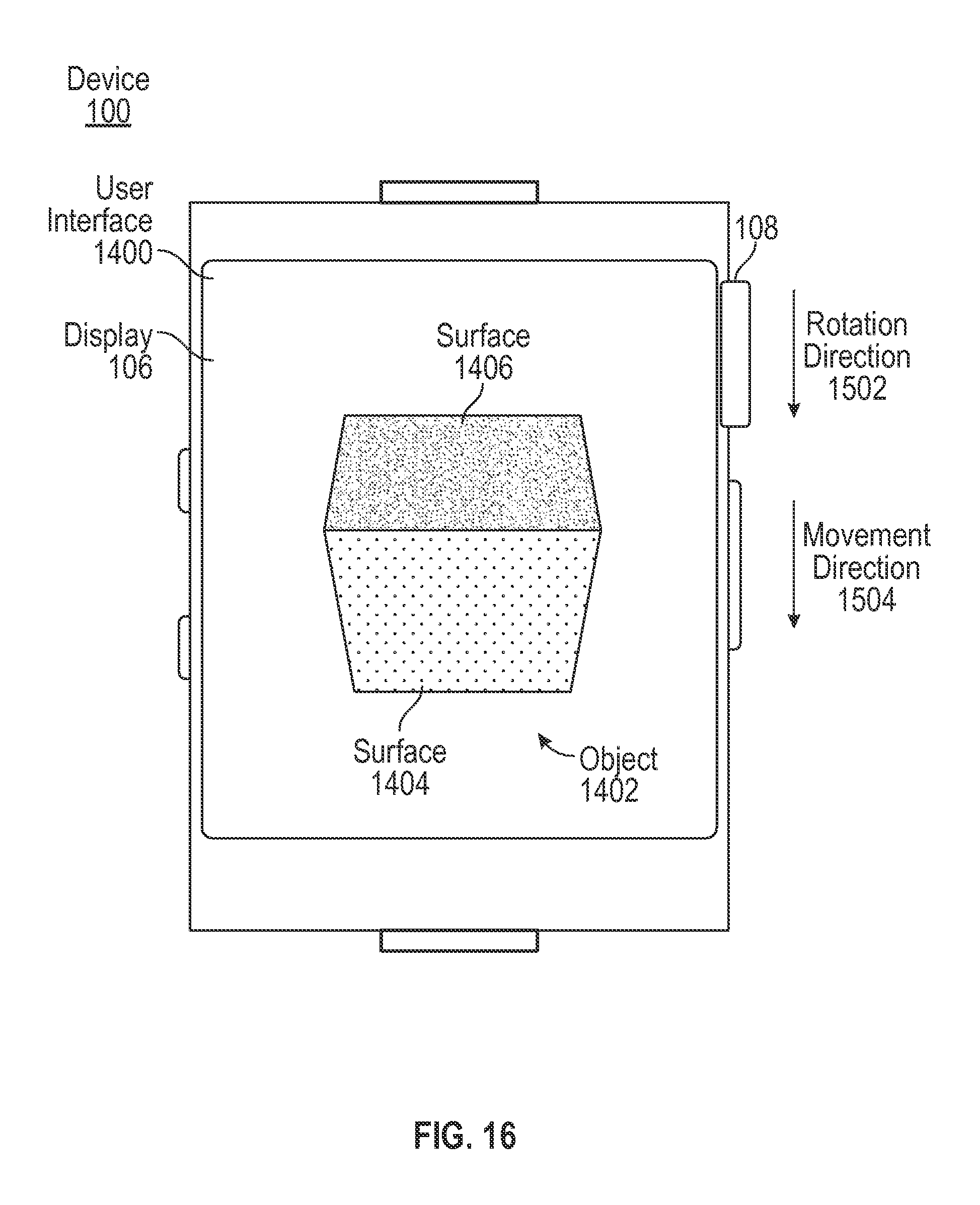
D00017
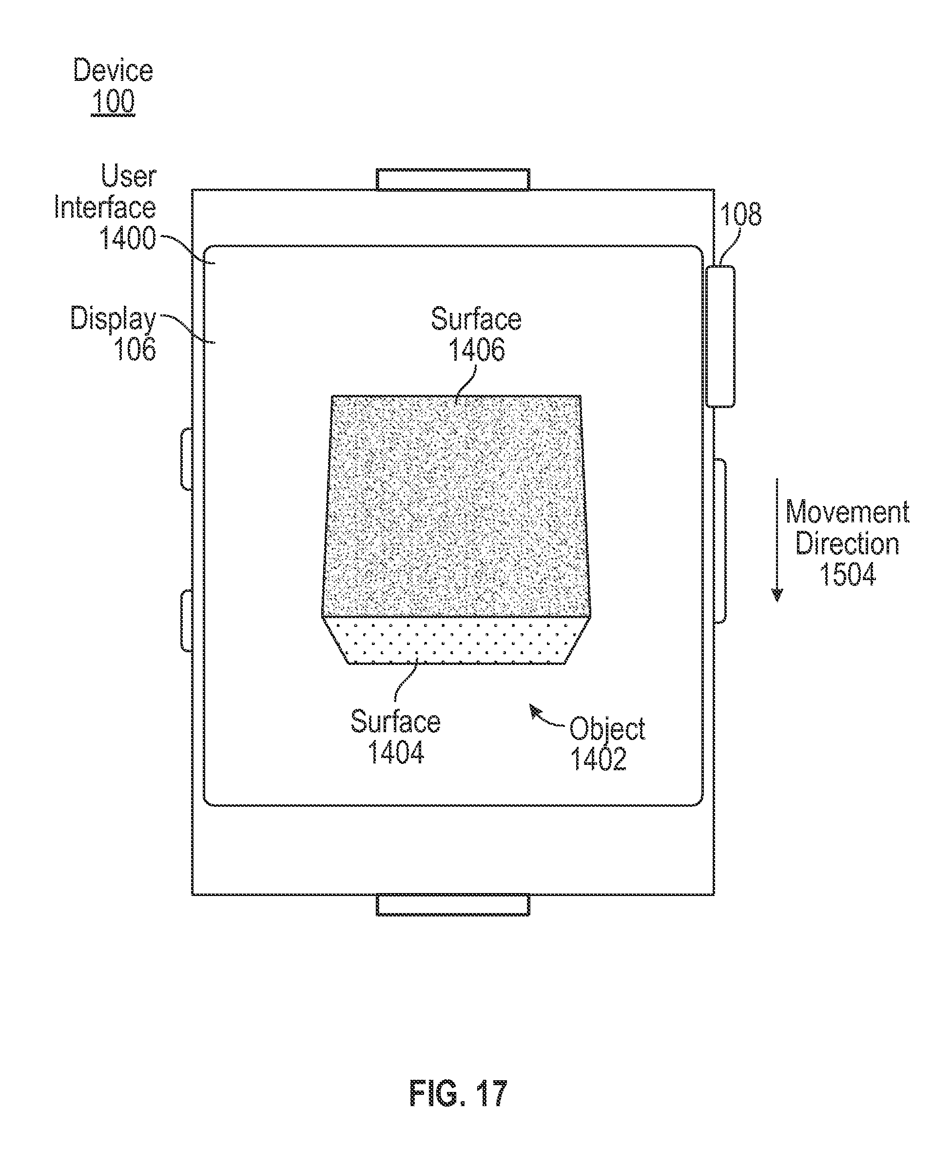
D00018
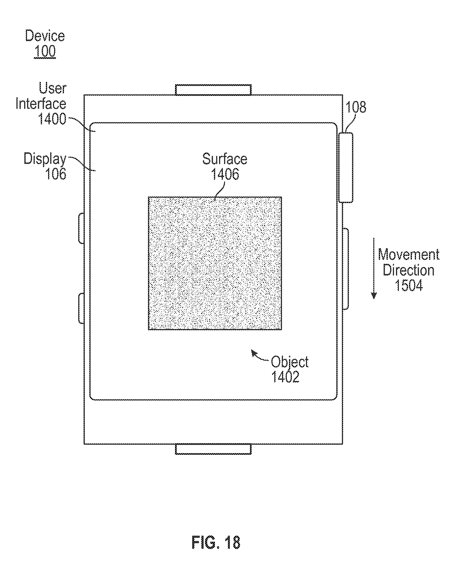
D00019
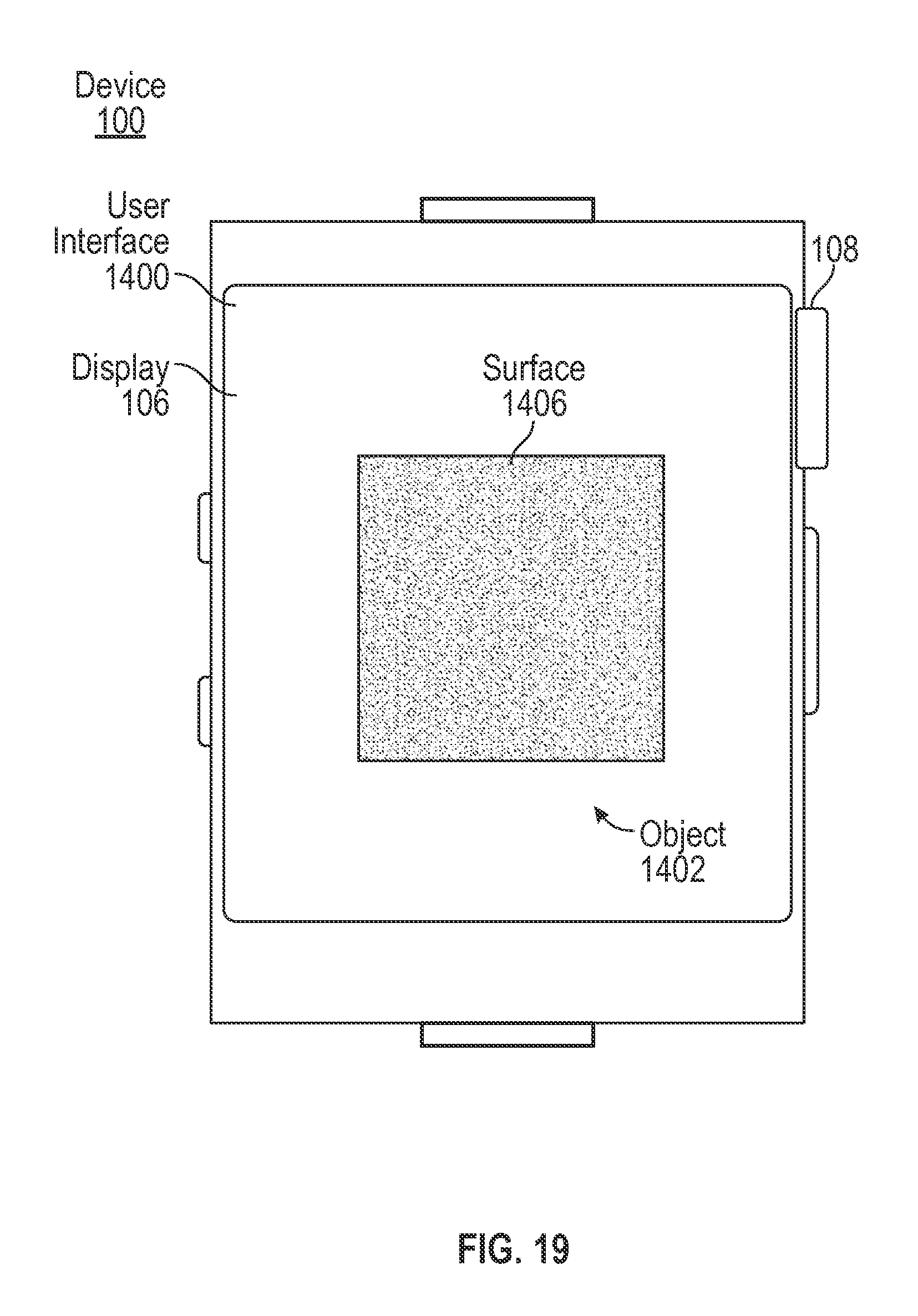
D00020

D00021

D00022

D00023
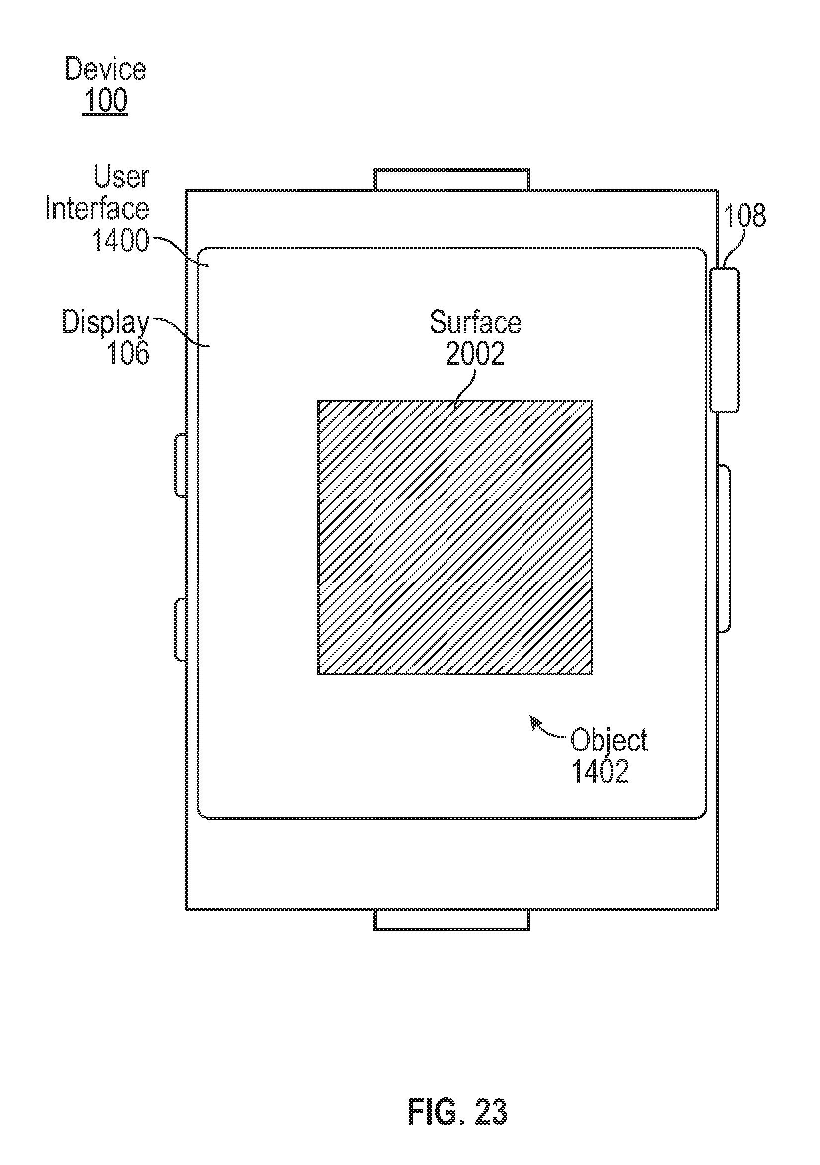
D00024

D00025

D00026

XML
uspto.report is an independent third-party trademark research tool that is not affiliated, endorsed, or sponsored by the United States Patent and Trademark Office (USPTO) or any other governmental organization. The information provided by uspto.report is based on publicly available data at the time of writing and is intended for informational purposes only.
While we strive to provide accurate and up-to-date information, we do not guarantee the accuracy, completeness, reliability, or suitability of the information displayed on this site. The use of this site is at your own risk. Any reliance you place on such information is therefore strictly at your own risk.
All official trademark data, including owner information, should be verified by visiting the official USPTO website at www.uspto.gov. This site is not intended to replace professional legal advice and should not be used as a substitute for consulting with a legal professional who is knowledgeable about trademark law.