Method for making a multilayer adhesive laminate
Miller, II
U.S. patent number 10,272,656 [Application Number 15/626,663] was granted by the patent office on 2019-04-30 for method for making a multilayer adhesive laminate. This patent grant is currently assigned to Mylan Inc.. The grantee listed for this patent is MYLAN INC.. Invention is credited to Kenneth J. Miller, II.


| United States Patent | 10,272,656 |
| Miller, II | April 30, 2019 |
Method for making a multilayer adhesive laminate
Abstract
A method allows for rapid manufacture of relatively thick adhesive coatings using a continuous process, where a single thin coating is continuously converted into a single thicker adhesive laminate. An exemplary process includes the steps of: (1) producing a web having a first surface with an adhesive layer and a second surface with a release liner; (2) slitting the web longitudinally into a first section and a second section; (3) laminating a backing film to the adhesive layer of the first section; (4) removing the release liner of the laminate of step (3) exposing the adhesive layer of the first section; and (5) laminating the second section to the laminate of step (4), wherein the adhesive layer of the laminate of step (4) is combined with the adhesive layer of the second section.
| Inventors: | Miller, II; Kenneth J. (Uniontown, PA) | ||||||||||
|---|---|---|---|---|---|---|---|---|---|---|---|
| Applicant: |
|
||||||||||
| Assignee: | Mylan Inc. (Canonsburg,
PA) |
||||||||||
| Family ID: | 41416092 | ||||||||||
| Appl. No.: | 15/626,663 | ||||||||||
| Filed: | June 19, 2017 |
Prior Publication Data
| Document Identifier | Publication Date | |
|---|---|---|
| US 20170282526 A1 | Oct 5, 2017 | |
Related U.S. Patent Documents
| Application Number | Filing Date | Patent Number | Issue Date | ||
|---|---|---|---|---|---|
| 13299747 | Nov 18, 2011 | 9731490 | |||
| 12571560 | Oct 1, 2009 | 8142592 | |||
| 61102223 | Oct 2, 2008 | ||||
| Current U.S. Class: | 1/1 |
| Current CPC Class: | B32B 38/1816 (20130101); C09J 7/38 (20180101); B32B 38/04 (20130101); C09J 7/10 (20180101); B32B 37/02 (20130101); Y10T 156/1069 (20150115); Y10T 156/1077 (20150115); C09J 2301/302 (20200801); Y10T 156/1075 (20150115); A61F 13/0253 (20130101); B32B 37/0053 (20130101); Y10T 156/1059 (20150115); B32B 2038/045 (20130101); Y10T 156/1062 (20150115); C09J 2301/208 (20200801) |
| Current International Class: | B32B 38/00 (20060101); A61F 13/00 (20060101); B32B 37/02 (20060101); B32B 38/04 (20060101); B32B 38/18 (20060101); C09J 7/38 (20180101); C09J 7/10 (20180101); B32B 37/00 (20060101); C09J 7/00 (20180101); A61F 13/02 (20060101) |
References Cited [Referenced By]
U.S. Patent Documents
| 2511559 | June 1950 | Banff et al. |
| 2649131 | August 1953 | Lincoln |
| 3247042 | April 1966 | Denton et al. |
| 3566752 | March 1971 | Dreher |
| 3632386 | January 1972 | Hurst |
| 3639500 | February 1972 | Muny et al. |
| 3655475 | April 1972 | Stelling, Jr. et al. |
| 3744383 | July 1973 | Finch et al. |
| 3993815 | November 1976 | Douek et al. |
| 4039705 | August 1977 | Douek et al. |
| 4104816 | August 1978 | Pingeton |
| 4163684 | August 1979 | Kartanson |
| 4201613 | May 1980 | Olivieri et al. |
| 4285999 | August 1981 | Olivieri et al. |
| 4398985 | August 1983 | Eagon |
| 4614076 | September 1986 | Rathemacher |
| 4759816 | July 1988 | Kasper et al. |
| 4837088 | June 1989 | Freedman |
| 4891260 | January 1990 | Kunkel et al. |
| 4940579 | July 1990 | Randen |
| 4994278 | February 1991 | Sablotsky et al. |
| 4995933 | February 1991 | Brussel |
| 5019204 | May 1991 | Brussel |
| 5082663 | January 1992 | Konishi et al. |
| 5085866 | February 1992 | Cowsar et al. |
| 5120544 | June 1992 | Henley |
| 5135798 | August 1992 | Muschter et al. |
| 5143570 | September 1992 | Freedman |
| 5234957 | August 1993 | Mantelle |
| 5288714 | February 1994 | Marschke |
| 5306504 | April 1994 | Lorenz |
| 5332576 | July 1994 | Mantelle |
| 5362516 | November 1994 | Wilson et al. |
| 5368860 | November 1994 | Sunami et al. |
| 5370941 | December 1994 | Kiang |
| 5383511 | January 1995 | Marasco |
| 5405366 | April 1995 | Fox et al. |
| 5411738 | May 1995 | Hind |
| 5446070 | August 1995 | Mantelle |
| 5476712 | December 1995 | Hartman et al. |
| 5514240 | May 1996 | Hagiiiri-Teiirani et al. |
| 5516581 | May 1996 | Kreckel et al. |
| 5536263 | July 1996 | Rolf et al. |
| 5558913 | September 1996 | Sasaki et al. |
| 5588962 | December 1996 | Nicholas et al. |
| 5589122 | December 1996 | Leonard et al. |
| 5589180 | December 1996 | Hind |
| 5589192 | December 1996 | Okabe et al. |
| 5597437 | January 1997 | Lange et al. |
| 5601838 | February 1997 | Hind |
| 5601839 | February 1997 | Quan et al. |
| 5656286 | August 1997 | Miranda et al. |
| 5686099 | November 1997 | Sablotsky et al. |
| 5709869 | January 1998 | Hind |
| 5719197 | February 1998 | Kanios et al. |
| 5741510 | April 1998 | Rolf et al. |
| 5744162 | April 1998 | Okabe et al. |
| 5776287 | July 1998 | Best et al. |
| 5776952 | July 1998 | Liedtke |
| 5810786 | September 1998 | Jackson et al. |
| 5827529 | October 1998 | Ono et al. |
| 5830497 | November 1998 | Yamanaka et al. |
| 5834010 | November 1998 | Quan et al. |
| 5840755 | November 1998 | Liedtke |
| 5900245 | May 1999 | Sawhney et al. |
| 5958446 | September 1999 | Miranda et al. |
| 6004665 | December 1999 | Luhmann et al. |
| 6059913 | May 2000 | Asmussen et al. |
| 6096333 | August 2000 | Rolf et al. |
| 6096334 | August 2000 | Rolf et al. |
| 6110488 | August 2000 | Hoffmann |
| 6117437 | September 2000 | Roreger |
| 6120792 | September 2000 | Juni |
| 6190689 | February 2001 | Hoffmann et al. |
| 6207184 | March 2001 | Ikeda et al. |
| 6218006 | April 2001 | Tokunaga et al. |
| 6280840 | August 2001 | Luhmann et al. |
| 6299902 | October 2001 | Jun et al. |
| 6313370 | November 2001 | Hyson |
| 6331336 | December 2001 | Szonn et al. |
| 6361790 | March 2002 | Rolf et al. |
| 6365178 | April 2002 | Venkateshwaran et al. |
| 6383511 | May 2002 | Cassel |
| 6420309 | July 2002 | Grime et al. |
| 6429228 | August 2002 | Inagi et al. |
| 6436530 | August 2002 | Szonn et al. |
| 6447787 | September 2002 | Gassner et al. |
| 6455066 | September 2002 | Fischer et al. |
| 6461644 | October 2002 | Jackson et al. |
| 6469227 | October 2002 | Cooke et al. |
| 6503620 | January 2003 | Xie et al. |
| 6528086 | March 2003 | Zhang |
| 6541098 | April 2003 | Venkatasanthanam et al. |
| 6544615 | April 2003 | Otten et al. |
| 6582724 | June 2003 | Hsu et al. |
| 6586000 | July 2003 | Luo et al. |
| 6627030 | September 2003 | Yang et al. |
| 6627620 | September 2003 | Nielsen |
| 6630486 | October 2003 | Royer |
| 6645521 | November 2003 | Cassel |
| 6663932 | December 2003 | McLaughlin et al. |
| 6663947 | December 2003 | Freedman et al. |
| 6673363 | January 2004 | Luo et al. |
| 6682757 | January 2004 | Wright |
| 6713144 | March 2004 | Bundo et al. |
| 6740379 | May 2004 | Congard et al. |
| 6746689 | June 2004 | Fischer et al. |
| 6761895 | July 2004 | Sawada et al. |
| 6767425 | July 2004 | Meier |
| 6808642 | October 2004 | Takaya et al. |
| 6818226 | November 2004 | Reed et al. |
| 6835256 | December 2004 | Menzies et al. |
| 6861068 | March 2005 | Ng et al. |
| 6871477 | March 2005 | Tucker |
| 6953513 | October 2005 | Volkert |
| 6953590 | October 2005 | Owaki et al. |
| 6980854 | December 2005 | Bernabei |
| 6998109 | February 2006 | Pearson et al. |
| 7018647 | March 2006 | Yamasaki et al. |
| 7022343 | April 2006 | Philbrook et al. |
| 7029693 | April 2006 | Hori et al. |
| 7063859 | June 2006 | Kanios et al. |
| 7094228 | August 2006 | Zhang et al. |
| 7101825 | September 2006 | Francis et al. |
| 7109161 | September 2006 | Gayed |
| 7186260 | March 2007 | Hyson |
| 7241357 | July 2007 | Roth et al. |
| 7264870 | September 2007 | Luhmann et al. |
| 7311954 | December 2007 | Koops et al. |
| 7335379 | February 2008 | Carrara et al. |
| 7458982 | December 2008 | Kraft et al. |
| 7476400 | January 2009 | Patel |
| 7479132 | January 2009 | Fukuta et al. |
| 7537590 | May 2009 | Santini, Jr. et al. |
| 7572613 | August 2009 | Klein |
| 7582783 | September 2009 | Blum |
| 2001/0021451 | September 2001 | Tokunaga et al. |
| 2002/0004065 | January 2002 | Kanios |
| 2002/0033225 | March 2002 | Becker et al. |
| 2002/0051875 | May 2002 | Luhmann et al. |
| 2002/0098347 | July 2002 | Szonn et al. |
| 2002/0110585 | August 2002 | Godbey et al. |
| 2002/0132008 | September 2002 | Mumper |
| 2002/0142042 | October 2002 | Mumper |
| 2002/0176841 | November 2002 | Barker et al. |
| 2003/0026932 | February 2003 | Johnson et al. |
| 2003/0027833 | February 2003 | Cleary et al. |
| 2003/0069318 | April 2003 | Dang et al. |
| 2003/0082225 | May 2003 | Mason |
| 2003/0082227 | May 2003 | Sournac et al. |
| 2003/0138503 | July 2003 | Staniforth et al. |
| 2003/0148949 | August 2003 | Podolsky et al. |
| 2003/0180347 | September 2003 | Young et al. |
| 2004/0013747 | January 2004 | Tucker |
| 2004/0028744 | February 2004 | Tongaree et al. |
| 2004/0072792 | April 2004 | Haraguchi et al. |
| 2004/0081685 | April 2004 | Wright |
| 2004/0101557 | May 2004 | Gibson et al. |
| 2004/0131665 | July 2004 | Wepfer |
| 2004/0214215 | October 2004 | Yu et al. |
| 2005/0002996 | January 2005 | Sojka |
| 2005/0003012 | January 2005 | Woller et al. |
| 2005/0019385 | January 2005 | Houze |
| 2005/0037200 | February 2005 | Wallach |
| 2005/0042173 | February 2005 | Besse et al. |
| 2005/0112183 | May 2005 | Galer |
| 2005/0115663 | June 2005 | Winkler |
| 2005/0202073 | September 2005 | Jackson et al. |
| 2005/0214376 | September 2005 | Faure et al. |
| 2005/0226910 | October 2005 | Sintov et al. |
| 2005/0228336 | October 2005 | Keusch et al. |
| 2005/0271729 | December 2005 | Wang |
| 2005/0281881 | December 2005 | Woeller et al. |
| 2006/0029654 | February 2006 | Cassel |
| 2006/0034904 | February 2006 | Weimann |
| 2006/0078604 | April 2006 | Kanios et al. |
| 2006/0088579 | April 2006 | Shastri et al. |
| 2006/0093673 | May 2006 | Coury |
| 2006/0178354 | August 2006 | Lucas |
| 2006/0188449 | August 2006 | Hirsh et al. |
| 2006/0193789 | August 2006 | Tamarkin et al. |
| 2006/0194759 | August 2006 | Eidelson |
| 2006/0198815 | September 2006 | Barker et al. |
| 2006/0198891 | September 2006 | Ravenelle et al. |
| 2006/0205678 | September 2006 | Gaeta et al. |
| 2006/0210613 | September 2006 | Carliss |
| 2006/0216245 | September 2006 | Haraguchi et al. |
| 2006/0240084 | October 2006 | Serafica et al. |
| 2006/0251890 | November 2006 | Lane et al. |
| 2006/0270736 | November 2006 | Pacheco |
| 2006/0293217 | December 2006 | Barker et al. |
| 2007/0042027 | February 2007 | Haley |
| 2007/0086955 | April 2007 | Kerdar et al. |
| 2007/0110805 | May 2007 | Levinson et al. |
| 2007/0166362 | July 2007 | Sakuma et al. |
| 2007/0166364 | July 2007 | Beier et al. |
| 2007/0203079 | August 2007 | Caldwell et al. |
| 2007/0207193 | September 2007 | Zasler et al. |
| 2007/0232985 | October 2007 | Sirkar et al. |
| 2007/0244294 | October 2007 | Pavlin |
| 2007/0248654 | October 2007 | Haley |
| 2007/0248655 | October 2007 | Haley |
| 2007/0264339 | November 2007 | Shah et al. |
| 2007/0269465 | November 2007 | Fita |
| 2007/0280972 | December 2007 | Zhang et al. |
| 2008/0015210 | January 2008 | Shah et al. |
| 2008/0021068 | January 2008 | Alam et al. |
| 2008/0114098 | May 2008 | Griswold et al. |
| 2008/0114284 | May 2008 | Anderson et al. |
| 2008/0145434 | June 2008 | Anderson et al. |
| 2008/0154210 | June 2008 | Jordan et al. |
| 2008/0166413 | July 2008 | Staniforth et al. |
| 2008/0182841 | July 2008 | Levine et al. |
| 2008/0206371 | August 2008 | Fontaine et al. |
| 2008/0220068 | September 2008 | Masini-eteve et al. |
| 2008/0233177 | September 2008 | Meconi |
| 2008/0255521 | October 2008 | Kubo et al. |
| 2008/0274164 | November 2008 | Vollmer |
| 2008/0286349 | November 2008 | Nomoto et al. |
| 2008/0287866 | November 2008 | Heller |
| 2008/0293015 | November 2008 | Wong et al. |
| 2008/0293703 | November 2008 | Richlin et al. |
| 2008/0299172 | December 2008 | Young et al. |
| 2008/0305155 | December 2008 | Jackson et al. |
| 2008/0317729 | December 2008 | Kasch et al. |
| 2008/0317863 | December 2008 | Nystrom et al. |
| 2009/0004281 | January 2009 | Nghiem et al. |
| 2009/0012067 | January 2009 | Rossetti et al. |
| 2009/0017125 | January 2009 | Lynenskjold et al. |
| 2009/0022801 | January 2009 | Vachon |
| 2009/0035377 | February 2009 | Houze |
| 2009/0036491 | February 2009 | Tucker et al. |
| 2009/0048296 | February 2009 | Campbell et al. |
| 2009/0048347 | February 2009 | Cohen et al. |
| 2009/0053290 | February 2009 | Sand et al. |
| 2009/0093547 | April 2009 | Corbitt et al. |
| 2009/0093669 | April 2009 | Farone et al. |
| 2009/0123527 | May 2009 | Alam et al. |
| 2009/0123528 | May 2009 | Fossel |
| 2009/0137473 | May 2009 | Martin et al. |
| 2009/0142401 | June 2009 | Appel et al. |
| 2009/0155235 | June 2009 | Cevc et al. |
| 2009/0162407 | June 2009 | Biggs et al. |
| 2009/0191127 | July 2009 | Saini |
| 2009/0196936 | August 2009 | John et al. |
| 200038096 | Oct 2000 | AU | |||
| 4 018 057 | Dec 1991 | DE | |||
| 0331392 | Sep 1989 | EP | |||
| 0387751 | Sep 1990 | EP | |||
| 0388306 | Sep 1990 | EP | |||
| 0507160 | Oct 1992 | EP | |||
| 0582727 | Feb 1994 | EP | |||
| 0583244 | Feb 1994 | EP | |||
| 0674913 | Oct 1995 | EP | |||
| 0737066 | Oct 1996 | EP | |||
| 1329225 | Jul 2003 | EP | |||
| 1572157 | Sep 2005 | EP | |||
| 1582220 | Oct 2005 | EP | |||
| 1702597 | Sep 2006 | EP | |||
| 59059612 | Apr 1984 | JP | |||
| 59059613 | Apr 1984 | JP | |||
| 59067218 | Apr 1984 | JP | |||
| 61093113 | May 1986 | JP | |||
| 61267510 | Nov 1986 | JP | |||
| 61267512 | Nov 1986 | JP | |||
| 62153227 | Jul 1987 | JP | |||
| 63132824 | Jun 1988 | JP | |||
| 63203630 | Aug 1988 | JP | |||
| 63313723 | Dec 1988 | JP | |||
| 01299216 | Dec 1989 | JP | |||
| 02071745 | Mar 1990 | JP | |||
| 04247027 | Sep 1992 | JP | |||
| 05170644 | Jul 1993 | JP | |||
| 05310559 | Nov 1993 | JP | |||
| 06072880 | Mar 1994 | JP | |||
| 06145051 | May 1994 | JP | |||
| 07076526 | Mar 1995 | JP | |||
| 07157424 | Jun 1995 | JP | |||
| 07215850 | Aug 1995 | JP | |||
| 07233054 | Sep 1995 | JP | |||
| 07277961 | Oct 1995 | JP | |||
| 07309756 | Nov 1995 | JP | |||
| 08225448 | Sep 1996 | JP | |||
| 09255565 | Sep 1997 | JP | |||
| 10147521 | Jun 1998 | JP | |||
| 2001302501 | Oct 2001 | JP | |||
| 2005126341 | May 2005 | JP | |||
| 2006248996 | Sep 2006 | JP | |||
| WO 1996/033678 | Oct 1996 | WO | |||
| WO 1998/017263 | Apr 1998 | WO | |||
| WO 2000/012172 | Mar 2000 | WO | |||
| WO 2000/056290 | Sep 2000 | WO | |||
| WO 2001/039754 | Jun 2001 | WO | |||
| WO 2001/041746 | Jun 2001 | WO | |||
| WO 2001/047559 | Jul 2001 | WO | |||
| WO 2002/017881 | Mar 2002 | WO | |||
| WO 2002/051382 | Jul 2002 | WO | |||
| WO 2003/011214 | Feb 2003 | WO | |||
| WO 2003/020824 | Mar 2003 | WO | |||
| WO 2003/066130 | Aug 2003 | WO | |||
| WO 2003/077885 | Sep 2003 | WO | |||
| WO 2003/099293 | Dec 2003 | WO | |||
| WO 2004/047819 | Jun 2004 | WO | |||
| WO 2004/060447 | Jul 2004 | WO | |||
| WO 2004/080441 | Sep 2004 | WO | |||
| WO 2004/103260 | Dec 2004 | WO | |||
| WO 2004/105868 | Dec 2004 | WO | |||
| WO 2004/110423 | Dec 2004 | WO | |||
| WO 2005/037336 | Apr 2005 | WO | |||
| WO 2005/042055 | May 2005 | WO | |||
| WO 2005/055977 | Jun 2005 | WO | |||
| WO 2005/092300 | Oct 2005 | WO | |||
| WO 2005/110626 | Nov 2005 | WO | |||
| WO 2005/113608 | Dec 2005 | WO | |||
| WO 2005/123046 | Dec 2005 | WO | |||
| WO 2006/017632 | Feb 2006 | WO | |||
| WO 2006/017852 | Feb 2006 | WO | |||
| WO 2006/039961 | Apr 2006 | WO | |||
| WO 2006/044206 | Apr 2006 | WO | |||
| WO 2006/084911 | Aug 2006 | WO | |||
| WO 2006/085101 | Aug 2006 | WO | |||
| WO 2006/088798 | Aug 2006 | WO | |||
| WO 2006/088875 | Aug 2006 | WO | |||
| WO 2006/091719 | Aug 2006 | WO | |||
| WO 2006/094681 | Sep 2006 | WO | |||
| WO 2006/113796 | Oct 2006 | WO | |||
| WO 2006/131806 | Dec 2006 | WO | |||
| WO 2007/022255 | Feb 2007 | WO | |||
| WO 2007/050580 | May 2007 | WO | |||
| WO 2007/062186 | May 2007 | WO | |||
| WO 2007/092350 | Aug 2007 | WO | |||
| WO 2007/098408 | Aug 2007 | WO | |||
| WO 2007/103555 | Sep 2007 | WO | |||
| WO 2007/110871 | Oct 2007 | WO | |||
| WO 2007/111370 | Oct 2007 | WO | |||
| WO 2007/111720 | Oct 2007 | WO | |||
| WO 2007/128349 | Nov 2007 | WO | |||
| WO 2007/133751 | Nov 2007 | WO | |||
| WO 2008/054362 | May 2008 | WO | |||
| WO 2008/113144 | Sep 2008 | WO | |||
| WO 2009/060629 | May 2009 | WO | |||
Other References
|
Abstract for DE 4018057. cited by applicant . International Search Report dated Jan. 19, 2010 for Application No. PCT/US209/059217. cited by applicant . Written Opinion dated Jan. 19, 2010 for Application No. PCT/US2009/059217. cited by applicant. |
Primary Examiner: Gray; Linda L
Parent Case Text
CROSS-REFERENCE TO RELATED APPLICATIONS
This application is a continuation of co-pending U.S. patent application Ser. No. 13/299,747, filed on Nov. 18, 2011; which is a continuation of U.S. patent application Ser. No. 12/571,560, filed on Oct. 1, 2009; which claims priority to U.S. Provisional Patent Application Ser. No. 61/102,223, filed on Oct. 2, 2008; the entire disclosures of which are hereby incorporated herein for all purposes.
Claims
What is claimed is:
1. A method of continuously manufacturing a multilayer pressure-sensitive adhesive laminate comprising the steps of: a. producing a web comprising a pressure-sensitive adhesive layer; b. slitting the web longitudinally into a first section and a second section; each section including a portion of the pressure-sensitive adhesive layer; wherein the first section and the second section are of substantially the same size; and c. laminating the first section and second section together such that the adhesive layers of the first and second sections are joined to form a combined adhesive layer.
2. The method of claim 1, comprising the step of positioning the first section and second section so the adhesive layer of the first section faces the adhesive layer of the second section along the length of the first and second sections.
3. The method of claim 2, wherein the act of positioning the first and second sections comprises turning a select one or both of the first section and the second section one or more times, such that the second section aligns with the first section with the adhesive layers of the first and second sections facing each other while traveling in the same direction.
4. The method of claim 3, wherein a select one or both of the first section and the second section are directed over one or more rollers, wherein the one or more rollers cause the select one or both of the first section and the second section to change direction of travel.
5. The method of claim 3, wherein the first section is directed over an about 45-degree turning roller, wherein the second section is directed over an about 90-degree turning roller, and wherein the second section is further directed over an about 45-degree turning roller.
6. The method of claim 3, wherein the first section is directed over one or more about 45-degree turning rollers, wherein the second section is directed over one or more about 45-degree turning rollers.
7. The method of claim 3, wherein the first section and second section are turned an unequal number of times.
8. A method of continuously manufacturing a multilayer pressure-sensitive adhesive laminate comprising the steps of: a. producing a web comprising a pressure-sensitive adhesive layer; b. slitting the web longitudinally into a first section and a second section; each section including a portion of the pressure-sensitive adhesive layer; wherein the first section and the second section are of substantially the same size; c. laminating a material to a first surface of the adhesive layer of the first section; wherein the material and the first surface of the adhesive layer of the first section are directly attached to each other; and d. laminating the adhesive layer of the second section to a second surface of the adhesive layer of the first section; wherein the adhesive layer of the second section and the second surface of the adhesive layer of the first section are joined to form a combined adhesive layer.
9. The method of claim 8, wherein the act of laminating the second section comprises turning a select one or both of the first section and the second section one or more times, such that the second section aligns with the first section with the adhesive layer of the second section facing the second surface of the adhesive layer of the first section.
10. The method of claim 9, wherein the second section is directed over an about 45-degree turning roller, wherein the first section with the material is directed over an about 45-degree turning roller.
11. The method of claim 9, wherein the first section and the second section are turned an equal number of times before laminating the second section to the second surface of the adhesive layer of the first section.
12. A method of continuously manufacturing a multilayer pressure-sensitive adhesive laminate comprising the steps of: a. coating a release liner with an adhesive layer; b. slitting the combined release liner and adhesive layer longitudinally into a first section and a second section; each section including a portion of the adhesive layer; wherein the first section and second section are of substantially the same size; and c. laminating the first section and second section together such that the adhesive layers of the first and second sections are joined to form a combined adhesive layer.
Description
FIELD OF THE INVENTION
This invention is in the field of pressure sensitive adhesive coatings.
BACKGROUND
Pressure-sensitive adhesive laminates are common in products from numerous industries, including the medical and consumer healthcare industries. Within these industries, pressure-sensitive adhesive laminates may be used for transdermal patches, medical tapes, wound dressings, and topical skin patches. While this section and the disclosure herein may focus on medical and consumer healthcare applications, it should be understood that this disclosure is not limited to these applications or industries.
A common process used to manufacture pressure-sensitive adhesive laminates involves a continuous solvent-based adhesive coating process. Such a process may employ any suitable type of solvent, including water. However, the thickness of the adhesive coating produced by such a process is limited. For instance, to achieve a thicker adhesive-coated product using a solvent-based adhesive coating processes, it is necessary to slow production speeds to give thicker adhesive coatings adequate drying time, or increase temperatures, which may cause the formation of surface imperfections. Alternatively, one may use such a process in batch mode to combine layers to produce thicker adhesive laminates. These approaches to producing thick or multilayer adhesive laminates are cost intensive and inefficient. Therefore, there is a need for a process that allows for continuous rapid manufacture of a relatively thick adhesive laminate.
SUMMARY
The processes described herein allow for continuous rapid manufacture of relatively thin adhesive coatings, where the thin coatings are continuously manufactured into a single thicker adhesive laminate.
In one embodiment, this disclosure pertains to a method of continuously manufacturing a multilayer pressure-sensitive adhesive laminate including the steps of: (1) producing a web having a first surface with an adhesive layer and a second surface with a release liner; (2) slitting the web longitudinally into a first section and a second section, each section having a first surface with an adhesive layer and a second surface with a release liner; (3) positioning the first section and second section so the adhesive layer of the first section faces the adhesive layer of the second section along the length of the first and second sections; and (4) laminating the first section and second section together such that the adhesive layers of the first and second sections are attached. The resultant laminate has two surfaces each having a release liner and an inner area having an adhesive layer.
In another embodiment, this disclosure pertains to a method of continuously manufacturing a multilayer pressure-sensitive adhesive laminate including the steps of: (1) producing a web having a first surface with an adhesive layer and a second surface with a release liner; (2) slitting the web longitudinally into a first section and a second section, each section having a first surface with an adhesive layer and a second surface with a release liner; (3) laminating a backing film to the adhesive layer of the first section; (4) removing the release liner of the laminate of step (3) and exposing the adhesive layer of the first section; (5) positioning the laminate of step (4) and the second section so the exposed adhesive layer of the laminate of step (4) faces the adhesive layer of the second section; and (6) laminating the second section to the laminate of step (4), wherein the adhesive layer of the laminate of step (4) is combined with the adhesive layer of the second section. The final laminate has one surface having a backing film, one surface having a release liner, and an inner area having an adhesive layer.
In another embodiment this disclosure pertains to a method of continuously manufacturing a multilayer pressure-sensitive adhesive laminate including the steps of: (1) producing a web having a first surface with an adhesive layer and a second surface with a release liner; (2) slitting the web longitudinally into a plurality of sections, each of the plurality of sections having a first surface with an adhesive layer and a second surface with a release liner; (3) laminating a backing film to the adhesive layer of a first section of the plurality of sections; (4) removing the release liner of the laminate of step (3) and exposing the adhesive layer associated with the first section; (5) positioning the laminate of step (4) and a next section of the plurality of sections so the exposed adhesive layer of the laminate of step (4) faces the adhesive layer of the next section; (6) laminating the next section to the laminate of step (4), wherein the adhesive layer of the laminate of step (4) is combined with the adhesive layer of the next section; (7) removing the release liner of the laminate of step (6) exposing the adhesive layer associated with the next section; and (8) repeating steps (5) through (7) to achieve a desired number of laminated layers; wherein step (7) is omitted with the final laminated section of the plurality of sections. The final laminate has one surface having a backing film, one surface having a release liner, and an inner area having an adhesive layer.
The above embodiments are exemplary only and should not be interpreted to limit the scope of this disclosure. It should be understood that this disclosure encompasses numerous embodiments, some of which are not explicitly disclosed within this section. Ultimately, the scope of this disclosure is defined by the broadest reading of the claims herein.
BRIEF DESCRIPTION OF THE DRAWINGS
The accompanying drawings are incorporated in and constitute a part of this specification. Together with the detailed description given below, the drawings serve to explain how the teachings of this application could be implemented. It should be understood that the teachings of this application are not limited to being implemented in the precise arrangements shown. In the drawings:
FIG. 1A depicts a flow diagram of a method to make a multilayer adhesive laminate having an adhesive coating between two release liners.
FIG. 1B depicts a schematic diagram of an exemplary process for the method shown in FIG. 1A.
FIG. 1C depicts a cross-section view of the adhesive coated release liner strips used in the lamination process of FIG. 1B.
FIG. 1D depicts a cross-section view of the multilayer adhesive laminate produced in the lamination process of FIG. 1B.
FIG. 2A depicts a flow diagram of a method to make a multilayer adhesive laminate having an adhesive coating between a release liner and a backing film.
FIG. 2B depicts a schematic diagram of an exemplary process for the method shown in FIG. 2A.
FIG. 2C depicts a cross-section view of the adhesive coated release liner strips used in the lamination process of FIG. 2B.
FIG. 2D depicts a cross-section view of the adhesive coated release liner strip containing the backing film as used in the lamination process of FIG. 2B.
FIG. 2E depicts a cross-section view of the strip of FIG. 2D with the release liner removed.
FIG. 2F depicts a cross-section view of the multilayer adhesive laminate produced in the lamination process of FIG. 2B.
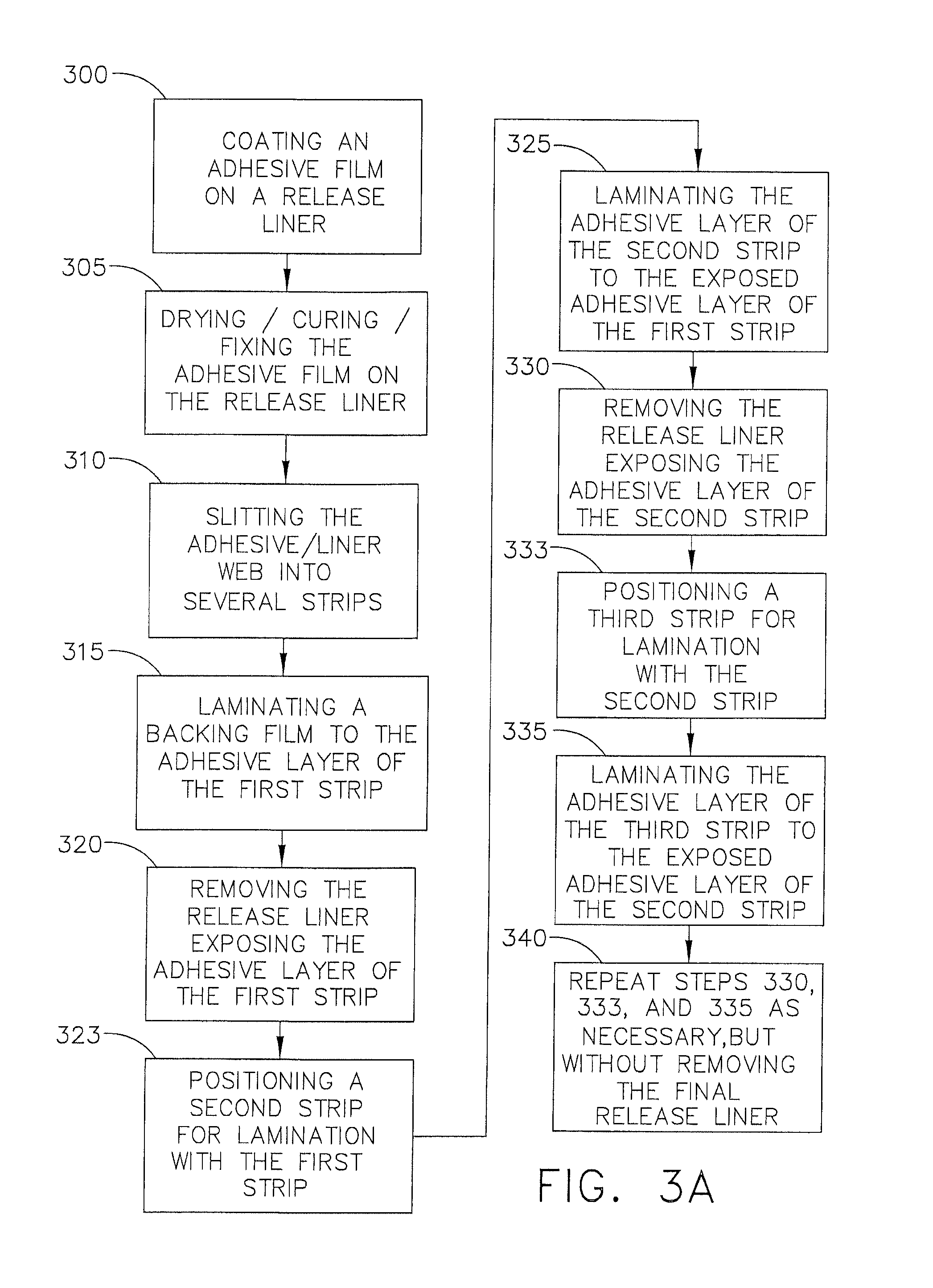
FIG. 3A depicts a flow diagram of a method to make a multilayer adhesive laminate having an adhesive coating between a release liner and a backing film.
FIG. 3B depicts a schematic diagram of an exemplary process for the method shown in FIG. 3A.
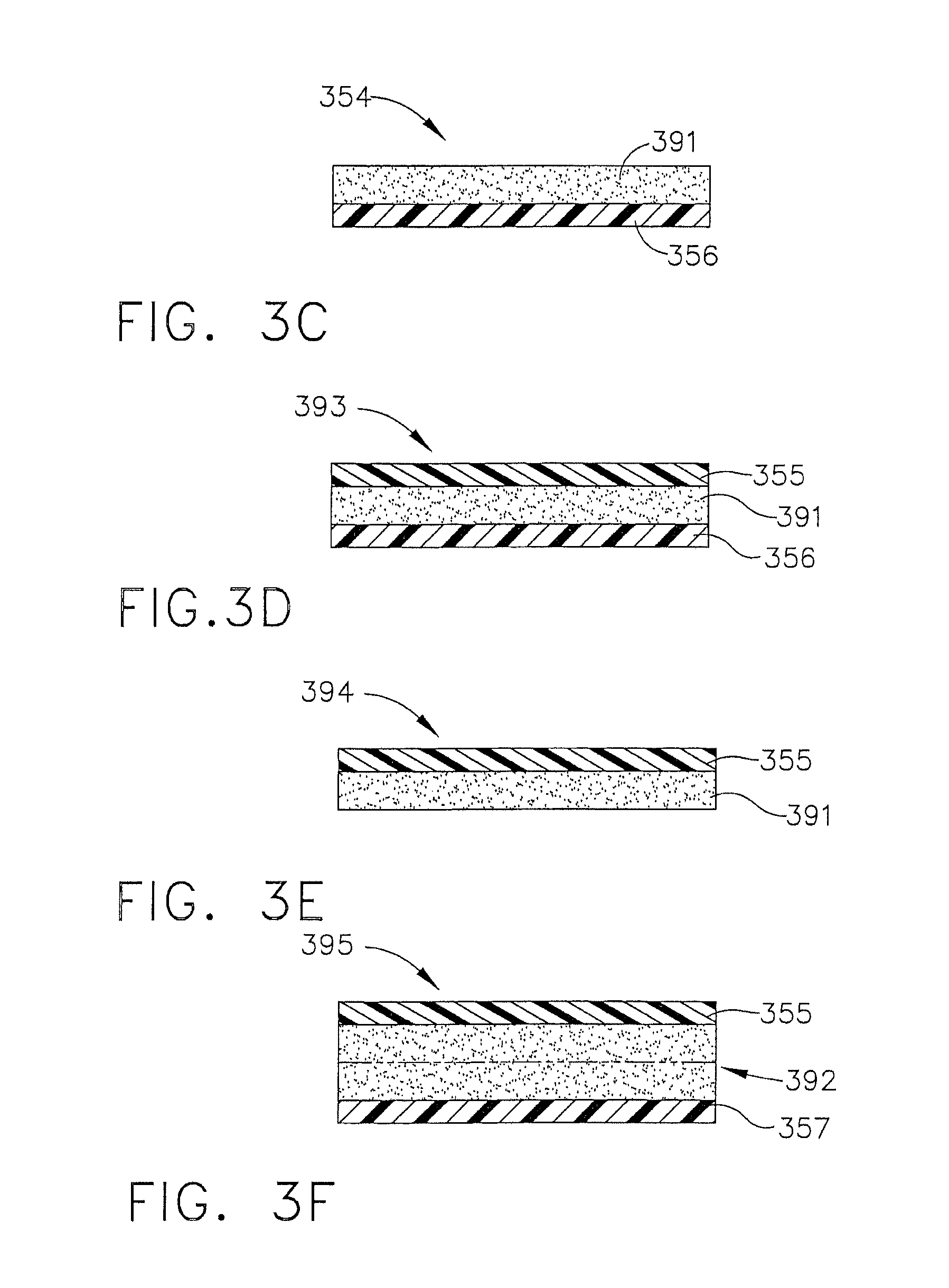
FIG. 3C depicts a cross-section view of the adhesive coated release liner strips used in the lamination process of FIG. 3B.
FIG. 3D depicts a cross-section view of the adhesive coated release liner strip containing the backing film as used in the lamination process of FIG. 3B.
FIG. 3E depicts a cross-section view of the strip of FIG. 3D with the release liner removed.
FIG. 3F depicts a cross-section view of the strip of FIG. 3E after an additional strip of adhesive coated release liner has been laminated to the strip of FIG. 3E.
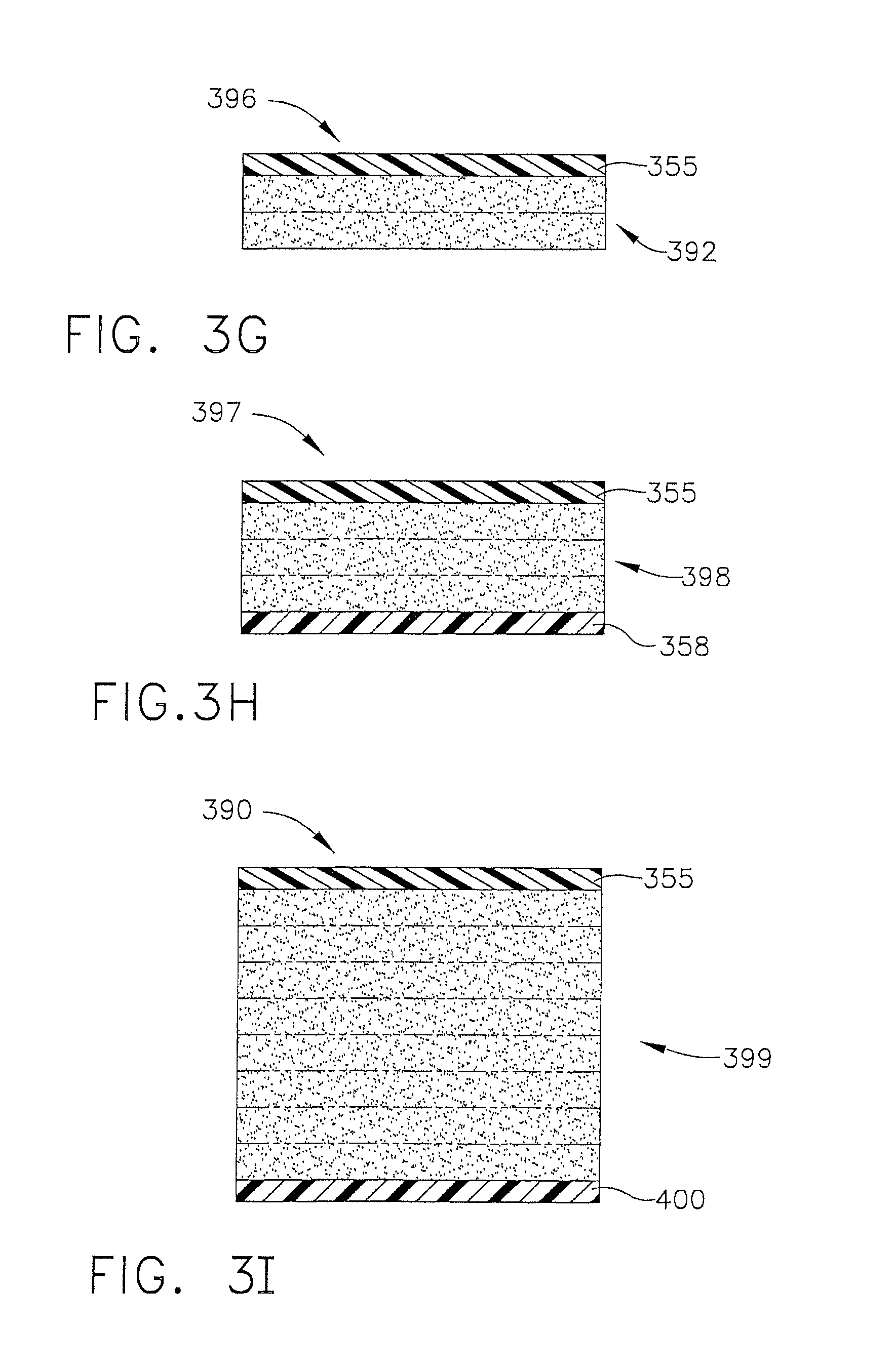
FIG. 3G depicts a cross-section view of the strip of FIG. 3F with the release liner removed.
FIG. 3H depicts a cross-section view of the strip of FIG. 3G after an additional strip of adhesive coated release liner has been laminated to the strip of FIG. 3G.
FIG. 3I depicts a cross-section view of the multilayer adhesive laminate produced in the lamination process of FIG. 3B.
DETAILED DESCRIPTION
In discussing the figures, specific frame of reference conventions are designated, which includes describing an upward and downward orientation. When viewing the exemplary process figures (FIGS. 1B, 2B, and 3B), an upward orientation is associated with an object facing out-of-the-page, whereas a downward orientation is associated with an object facing into-the-page. When viewing the laminate schematic figures (FIGS. 1C-1D, 2C-2F, and 3C-3I), an upward orientation is associated with an object facing the top of the page, whereas a downward orientation is associated with an object facing the bottom of the page. These frame of reference conventions are used only for aiding in understanding the disclosure. In no sense should the disclosure be limited to such a frame of reference as other suitable manners of description fall within the scope of this disclosure.
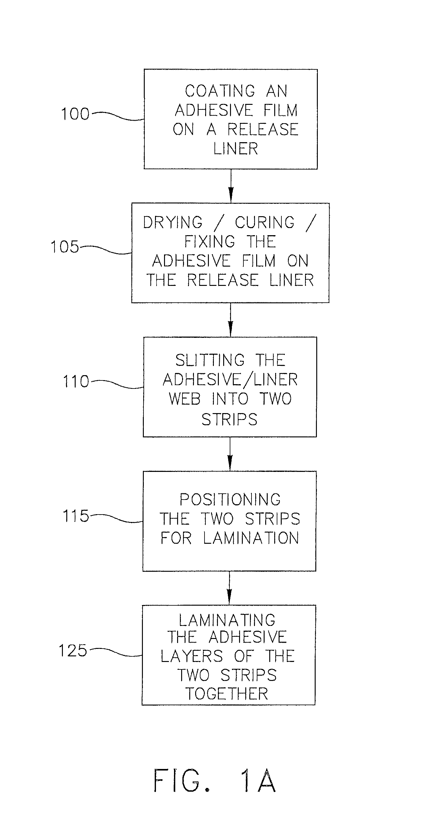
FIG. 1A describes a process for manufacturing a multilayer adhesive laminate by pairing two adhesive coatings between release liners. At step 100, a coating of adhesive is applied to a release liner, using any suitable coating method, to produce a coated web. Step 105 is a curing process, using any suitable method, where the adhesive-coated web is converted from a fluid to a fixed film. A suitable curing process may include, but is not limited to, a drying process. At step 110, the cured web is slit into two strips using any suitable slitting method. At step 115, the separate strips are directed through the process to orient the adhesive layers of the two strips such that they face one another in preparation for lamination. At step 125, the adhesive layers of the two strips are laminated together, using any suitable lamination method, to form a multilayer adhesive laminate having an inner adhesive layer surrounded on both sides by a release liner.
Referring to FIG. 1B, a schematic shows an exemplary way to direct the strips to achieve the multilayer adhesive laminate discussed in FIG. 1A. In FIG. 1B, web section 130 is the adhesive coated web after curing step 105 of FIG. 1A. Web section 130 travels through slitter 135 where web section 130 is divided into strip sections 140 and 145. Strip section 140 travels over 45-degree turning roller 160, which causes a change in the surface orientation of strip section 140, and causes strip section 140 to change its direction of travel by about 90-degrees. FIGS. 1B and 1C show that before strip section 140 passes over 45-degree turning roller 160, adhesive layer 175 of strip section 140 faces upward (and conversely the release liner 180 faces downward). After passing over 45-degree turning roller 160, adhesive layer 175 of strip section 140 faces downward (and conversely the release liner 180 faces upward).
Still referring to FIG. 1B, strip section 145 is directed to 90-degree turning roller 150, which causes a change in the surface orientation of strip section 145, and causes strip section 145 to reverse its direction of travel. As shown for FIGS. 1B and 1C, adhesive layer 190 of strip section 145 faces upward (and conversely the release liner 185 faces downward) before passing over 90-degree turning roller 150. After passing over 90-degree turning roller 150, adhesive layer 190 of strip section 145 faces downward (and conversely the release liner 185 faces upward). Strip section 145 is then directed to 45-degree turning roller 155, which causes a change in the surface orientation of strip section 145, and causes strip section 145 to change its direction of travel by about 90-degrees. As shown in FIG. 1B, 45-degree turning roller 155 is located such that after turning roller 155, strip section 145 aligns with strip section 140, and strip section 140 travels above strip section 145 in the same direction. Those of ordinary skill in the art will appreciate that heights of strip sections 140 and 145 may be manipulated by positioning turning rollers or web guides at different heights with respect to a common plane of reference. Furthermore, as shown in FIG. 1B, after passing over 45-degree turning roller 155, adhesive layer 190 of strip section 145 now faces adhesive layer 175 of strip section 140.
Still referring to FIG. 1B, with strip sections 140 and 145 oriented as described above, strip sections 140 and 145 then pass through a lamination section 165. Lamination section 165 causes the adhesive layers 175 and 190, of strip sections 140 and 145 respectively, to join forming a multilayer adhesive laminate 170. As shown in FIGS. 1B and 1D, the multilayer adhesive laminate 170 has a combined adhesive layer 195, surrounded on either side by release liners 180 and 185. It should be noted that combined adhesive layer 195 is comprised of adhesive layer 175 of strip section 140 and adhesive layer 190 of strip section 145.
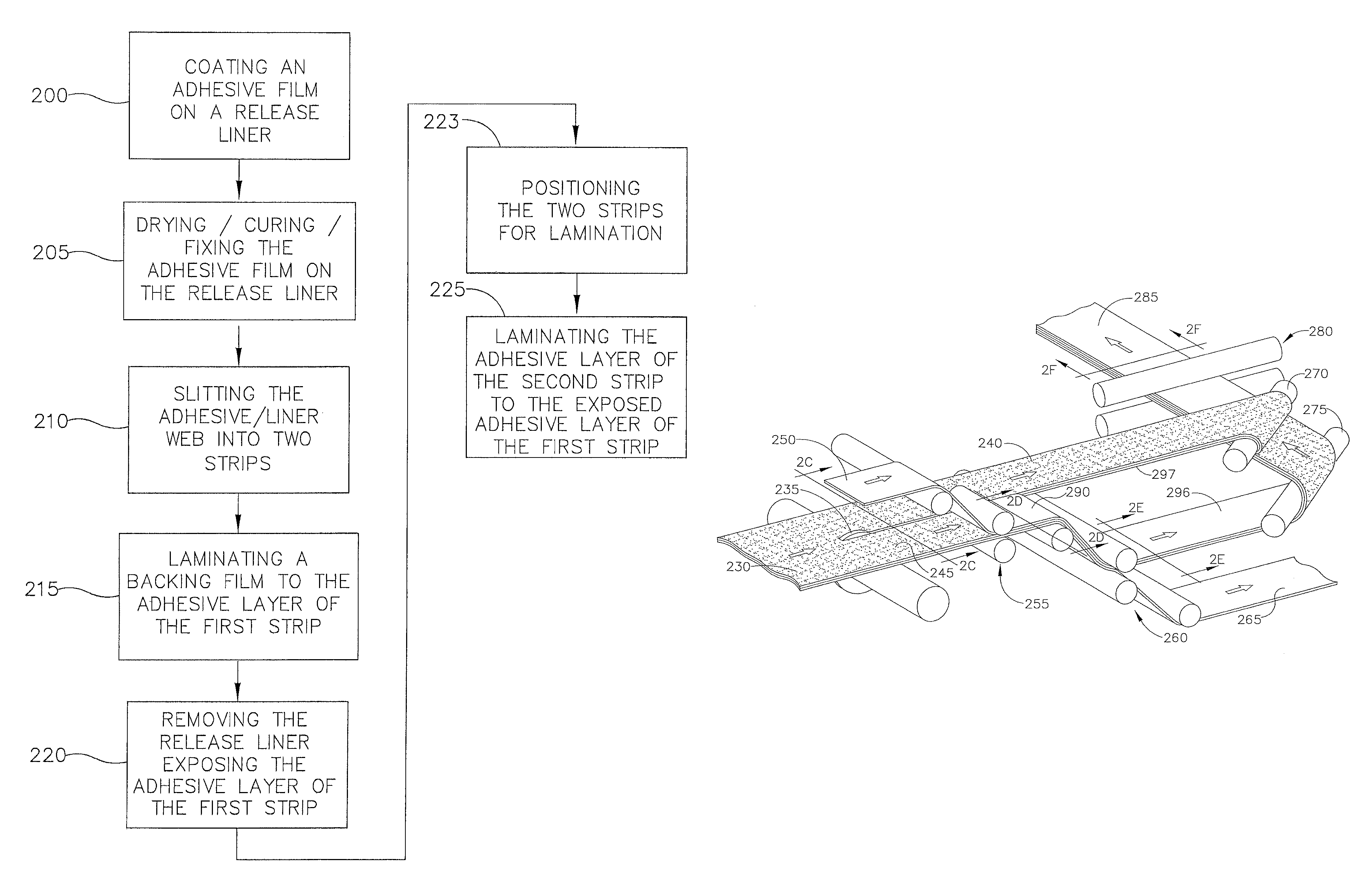
Now referring to FIG. 2A, a process is shown for manufacturing a multilayer adhesive laminate by pairing two adhesive coatings between a release liner and a backing film. At step 200, an adhesive coating is applied to a release liner using any suitable coating method. At step 205, the web containing the adhesive coating and release liner is cured using any suitable method. At step 210, the web is slit into two strips using any suitable slitting method. At step 215 a backing film is attached to the adhesive layer of one of the strips. From this same strip, at step 220, the release liner is removed, thus exposing the adhesive layer of the strip opposite the side of the backing film. At step 223, the separate strips are then directed through the process to orient the adhesive layers of the two strips such that they face one another in preparation for lamination. At step 225 the adhesive layers of the two strips are laminated together using any suitable lamination method to form a multilayer adhesive laminate.
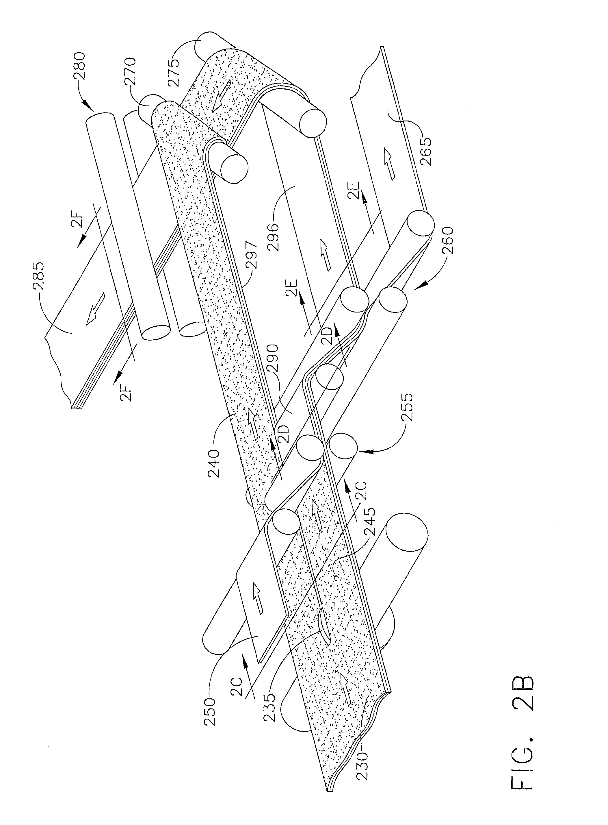
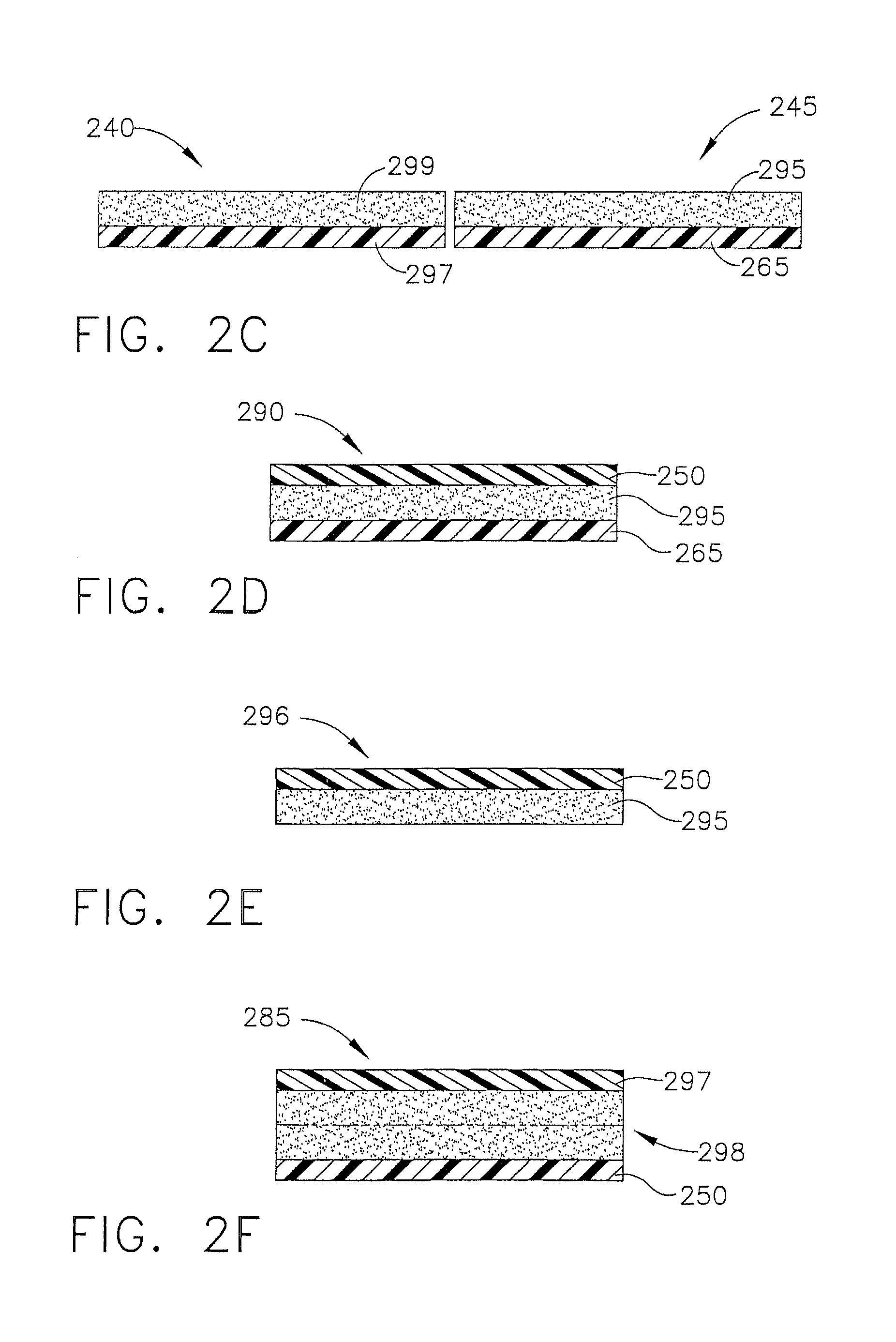
Referring to FIGS. 2B-2F, a schematic shows an exemplary way to direct the strips to achieve the multilayer adhesive laminate discussed in FIG. 2A. In FIG. 2B, web section 230 is the adhesive-coated web after curing step 205 of FIG. 2A. Web section 230 travels through slitter 235 where web section 230 is divided into strip sections 240 and 245. Strip section 245 travels to backing film application section 255, where backing film 250 is attached to adhesive layer 295 of strip section 245 to produce strip section 290 having a backing film 250, an adhesive layer 295, and a release liner 265 as shown in FIGS. 2B and 2D. Strip section 290 then travels to a release liner removal section 260. Release liner 265 is removed from strip section 290 to produce strip section 296. As shown in FIG. 2E, strip section 296 has backing film 250 on top of adhesive layer 295, which now has an exposed adhesive surface where release liner 265 was formerly positioned. Strip section 296 travels over 45-degree turning roller 275, which causes a change in the surface orientation of strip section 296, and causes strip section 296 to change its direction of travel by about 90-degrees. FIGS. 2B and 2E show that before strip section 296 passes over 45-degree turning roller 275, backing film 250 of strip section 296 faces upward (and conversely the adhesive layer 295 faces downward). After passing over 45-degree turning roller 275, backing film 250 of strip 296 faces downward (and conversely the adhesive layer 295 faces upward).
Still referring to FIGS. 2B-2F, strip section 240 is directed into 45-degree turning roller 270, which causes a change in the surface orientation of strip section 240, and causes strip section 240 to change its direction of travel by about 90-degrees. FIGS. 2B and 2C show that before strip section 240 passes over 45-degree turning roller 270, adhesive layer 299 of strip section 240 faces upward (and conversely the release liner 297 faces downward). After passing over 45-degree turning roller 270, adhesive layer 299 of strip section 240 faces downward (and conversely the release liner 297 faces upward). As shown in FIG. 2B, 45-degree turning rollers 270 and 275 are located such that strip sections 240 and 296 align, and such that strip section 240 is traveling above strip section 296 and in the same direction and speed. Those of ordinary skill in the art will appreciate that heights of strip sections 240 and 296 may be manipulated by positioning turning rollers or web guides at different heights with respect to a common plane of reference. Furthermore, as shown in FIGS. 2B, 2C, and 2E, after passing over 45-degree turning roller 270, adhesive layer 299 of strip section 240 is now oriented facing adhesive layer 295 of strip section 296.
Still referring to FIGS. 2B-2F, with strip sections 240 and 296 oriented as described above, strip sections 240 and 296 then pass through a lamination section 280. Lamination section 280 causes the adhesive layers of strip sections 240 and 296, to join forming a multilayer adhesive laminate 285. As shown in FIGS. 2B and 2F, the multilayer adhesive laminate 285 has a combined adhesive layer 298 surrounded on one side by backing film 250 and one the other side by release liner 297. It should be noted that combined adhesive layer 298 is comprised of adhesive layer 299 of strip section 240 and adhesive layer 295 of strip section 245.
Now referring to FIG. 3A, a process is shown for manufacturing a multilayer adhesive laminate by combining a multitude of adhesive coatings between a single release liner and single backing film. At step 300, an adhesive coating is applied to a release liner using any suitable coating method. At step 305, the web containing the adhesive-coating and release liner is cured using any suitable method. At step 310 the web is slit into several strips using any suitable slitting method. At step 315 a backing film is attached to the adhesive layer of a first strip. From this first strip, at step 320, the release liner is removed, thus exposing the adhesive layer of the first strip, opposite the side of the backing film. At step 323, a second strip is then directed through the process to orient its adhesive layer such that it faces the exposed adhesive layer of the first strip. At step 325, the adhesive layer of the second strip is laminated to the exposed adhesive layer of the first strip using any suitable lamination process. At step 330, the release liner of the second strip is removed, thus exposing the adhesive layer of the second strip, opposite the side laminated to the first strip. At step 333, a third strip is then directed through the process to orient its adhesive layer such that it faces the exposed adhesive layer of the second strip. At step 335, the adhesive layer of the third strip is laminated to the exposed adhesive layer of the second strip using any suitable lamination process. At step 340, steps 330, 333, and 335 are repeated with the next available strip for lamination. However, step 340 concludes by not removing the release liner of the final laminated strip, thus forming the multilayer adhesive laminate.
Referring to FIGS. 3B-3H, a schematic shows an exemplary way to direct the strips to achieve the multilayer adhesive laminate discussed in FIG. 3A. In FIG. 3B, web section 345 is the adhesive coated web after curing step 305 of FIG. 3A. Web section 345 travels through slitter section 346 where web section 345 is divided into a plurality of strip sections 347, 348, 349, 350, 351, 352, 353, and 354. Strip section 354 has an adhesive layer 391 on a release liner 356 as shown in FIG. 3C. Each of strip sections 347, 348, 349, 351, 352, and 353 have a similar adhesive layer on release liner structure as shown in FIG. 3C with respect to strip section 354.
Still referring to FIGS. 3B-3H, strip section 354 travels to backing film application section 363, where backing film 355 is attached to adhesive layer 391 of strip section 354 to produce a strip section 393 having a backing film 355, an adhesive layer 391, and a release liner 356 as shown in FIG. 3D. Strip section 393 then travels to a release liner removal section 371. Release liner 356 is removed from strip section 393 to produce strip section 394. As shown in FIG. 3E, strip section 394 has backing film 355 on adhesive layer 391, which now has an exposed adhesive surface where release liner 356 was formerly positioned.
Strip section 353 travels into 45-degree turning roller (shown in phantom in drawing), which causes a change in the surface orientation of strip section 353, and causes strip section 353 to change its direction of travel by about 90-degrees. FIG. 3B shows that before strip section 353 passes over the 45-degree turning roller, the adhesive layer of strip section 353 faces upward (and conversely the release liner 357 faces downward). After passing over the 45-degree turning roller, the adhesive layer of strip section 353 faces downward (and conversely the release liner 357 faces upward). Strip section 353 continues into another 45-degree turning roller (shown in phantom in drawing), which again causes a change in the surface orientation of strip section 353, and causes strip section 353 to change its direction of travel by about 90-degrees. FIG. 3B shows that before strip section 353 passes over the second 45-degree turning roller, the adhesive layer of strip section 353 faces downward (and conversely the release liner 357 faces upward). After passing over the second 45-degree turning roller, the adhesive layer of strip section 353 faces upward (and conversely the release liner 357 faces downward). As shown in FIGS. 3B and 3E, the 45-degree turning rollers that guide strip section 353 are located such that, at the exit of the second 45-degree turning roller, strip section 353 aligns with strip section 394, and strip section 353 is traveling below strip section 394 in the same direction and speed. Those of ordinary skill in the art will appreciate that heights of strip sections 353 and 394 may be manipulated by positioning turning rollers or web path guides at different heights with respect to a common plane of reference. Furthermore, after passing over the second 45-degree turning roller, the adhesive layer of strip section 353 faces the exposed adhesive layer 391 of strip section 394.
Still referring to FIGS. 3B-3H, with strip sections 353 and 394 oriented as described above, strip sections 353 and 394 then pass through a lamination section 364. Lamination section 364 causes the adhesive layers of strip sections 353 and 394, to join together forming a strip section 395 as shown in FIG. 3F. Strip section 395 has a combined adhesive layer 392 surrounded on one side by backing film 355 and on the opposite side by release liner 357. It should be noted that combined adhesive layer 392 is comprised of adhesive layer 391 of strip section 394 and the adhesive layer of strip section 353.
Still referring to FIGS. 3B-3H, strip section 395 then travels to a release liner removal section 372. Release liner 357 is removed from strip section 395 to produce strip section 396. As shown in FIG. 3G, strip section 396 has backing film 355 on top of combined adhesive layer 392, which now has an exposed adhesive surface where release liner 357 was formerly positioned.
Strip section 352 travels into 45-degree turning roller 383, which causes a change in the surface orientation of strip section 352, and causes strip section 352 to change its direction of travel by about 90-degrees. FIG. 3B shows that before strip section 352 passes over 45-degree turning roller 383, the adhesive layer of strip section 352 faces upward (and conversely the release liner 358 faces downward). After passing over 45-degree turning roller 383, the adhesive layer of strip section 352 faces downward (and conversely the release liner 358 faces upward). Strip section 352 continues into another 45-degree turning roller 389, which again causes a change in the surface orientation of strip section 352, and causes strip section 352 to change its direction of travel by about 90-degrees. FIG. 3B shows that before strip section 352 passes over 45-degree turning roller 389, the adhesive layer of strip section 352 faces downward (and conversely the release liner 358 faces upward). After passing over 45-degree turning roller 389, the adhesive layer of strip section 352 faces upward (and conversely the release liner 358 faces downward). As shown in FIGS. 3B and 3G, 45-degree turning rollers 383, 389 that guide strip section 352 are located such that, at the exit of 45-degree turning roller 389, strip section 352 aligns with strip section 396, and strip section 352 is traveling below strip section 396 in the same direction and speed. Those of ordinary skill in the art will appreciate that heights of strip sections 352 and 396 may be manipulated by positioning turning rollers or web path guides at different heights with respect to a common plane of reference. Furthermore, after passing over 45-degree turning roller 389, the adhesive layer of strip section 352 faces the exposed adhesive layer 392 of strip section 396.
Still referring to FIGS. 3B-3H, with strip sections 352 and 396 oriented as described above, strip sections 352 and 396 then pass through a lamination section 365. Lamination section 365 causes the adhesive layers of strip sections 352 and 396, to join forming a strip section 397 as shown in FIG. 3H. Strip section 397 has a combined adhesive layer 398 surrounded on one side by backing film 355 and on the opposite side by release liner 358. It should be noted that combined adhesive layer 398 is comprised of adhesive layer 392 of strip section 396 and the adhesive layer of strip section 352.
As shown in FIGS. 3A and 3B, the process described in the preceding paragraphs repeats to achieve the desired laminate thickness. More specifically, release liner 358 of strip section 397 is removed and strip section 351 is positioned using 45-degree turning rollers for lamination. As shown in FIG. 3B, after final strip section 347 is laminated to the intermediate product, the release liner of strip section 347 is maintained on the laminate to produce the final multilayer adhesive laminate 390 as shown in FIGS. 3B and 3I. The final multilayer adhesive laminate 390 has a combined adhesive layer 399 surrounded on one side by backing film 355 and on the other side by release liner 400. It should be noted that combined adhesive layer 399 is comprised of the adhesive layers of strip sections 354, 353, 352, 351, 350, 349, 348, and 347.
While the above paragraphs have described several product features, this disclosure should not be limited to the precise features shown and described. For example, the adhesive coating disclosed may be of any of several types. For instance, the adhesive coating may be a solvent based adhesive coating for use in a transdermal or topical medical patch. In such examples, the adhesive coating may contain medicinal formulations for the treatment of certain ailments. By way of example and not limitation, to treat skin pain or discomfort, lidocaine may be combined with the adhesive to create a skin treatment patch. Those of ordinary skill in the art will appreciate that the adhesive may be combined with any suitable medicinal formulation, where topical or transdermal drug delivery is desired.
Additional medical related applications for a multilayer adhesive laminate as disclosed herein may include medical tapes, wound dressings, ostomy adhesives, and numerous others. Similarly, the multilayer adhesive laminate disclosed herein, may have applications in other industries where a thick coating of pressure-sensitive adhesive is desirable; for example, applications may exist in consumer products, automotive, and home improvement industries.
Some additional product features described include release liners and backing films. It should be understood that this disclosure shall encompass any variety of release liners and backing films suitable for adhering to an adhesive coating. By way of example only, release liners and backing films may be manufactured from natural or synthetic fibers that may be woven, nonwoven, melt cast, or extruded. Furthermore, a combination of natural or synthetic fibers may be used. Those of ordinary skill in the art will appreciate the variety of materials suitable for use as both release liners and backing films.
The above disclosure also describes several process features, and the disclosure should not be limited to the precise process features shown or described. For example, several web-guiding structures are disclosed including 45-degree and 90-degree turning rollers. It should be understood, that in some embodiments such turning rollers may be driven or braked, while in other embodiments such turning rollers may be freely rotating. Still in other embodiments, turning rollers may be interchanged with turning or guide bars that do not rotate. Similarly, the precise degrees specified for the turning rollers are not required and may be substituted with turning rollers having other degree configurations.
Some additional process features described include coating, curing, slitting, and laminating processes. It should be understood that this disclosure is not intended to be limited to a specific method for conducting any of these processes. For example, several types of coating, curing, slitting, and laminating processes may be compatible with this disclosure. By way of example only, the adhesive coating may be accomplished in a spray application, a metered roller application, or any other suitable coating method. By way of example only, the curing process may be accomplished using a steam-filled-can drying system, a through-air drying system, a radiation curing system, or any other suitable method. By way of example only, the slitting process may be accomplished using a slitting blade that may be comprised of a metal or ceramic, a rotating slitting wheel, an air or water jet, or any other suitable slitting method. By way of example only, the laminating process may be accomplished by compressing the laminate layers between two rollers, by ultrasonic bonding, by chemical adhesion, or any other suitable laminating method. Those of ordinary skill in the art will appreciate the variety of methods suitable for use in coating, curing, slitting, and laminating.
Having shown and described various embodiments, further adaptations of the methods and systems described herein may be accomplished by appropriate modifications by one of ordinary skill in the art without departing from the scope of this disclosure. Several of such potential modifications have been mentioned, and others will be apparent to those skilled in the art. For instance, the examples, embodiments, geometries, materials, dimensions, ratios, steps, and the like discussed above are illustrative and are not required. Accordingly, the scope of the present invention should be considered in terms of whatever claims recite the invention, and is understood not to be limited to the details of structure and operation shown and described in the description.
* * * * *
D00000
D00001
D00002
D00003
D00004
D00005
D00006
D00007
D00008
D00009
D00010
XML
uspto.report is an independent third-party trademark research tool that is not affiliated, endorsed, or sponsored by the United States Patent and Trademark Office (USPTO) or any other governmental organization. The information provided by uspto.report is based on publicly available data at the time of writing and is intended for informational purposes only.
While we strive to provide accurate and up-to-date information, we do not guarantee the accuracy, completeness, reliability, or suitability of the information displayed on this site. The use of this site is at your own risk. Any reliance you place on such information is therefore strictly at your own risk.
All official trademark data, including owner information, should be verified by visiting the official USPTO website at www.uspto.gov. This site is not intended to replace professional legal advice and should not be used as a substitute for consulting with a legal professional who is knowledgeable about trademark law.