Apparatus for gliding over snow
Mozlin , et al.
U.S. patent number 10,265,605 [Application Number 16/121,793] was granted by the patent office on 2019-04-23 for apparatus for gliding over snow. The grantee listed for this patent is Kyle Mozlin, Ryan Mozlin. Invention is credited to Kyle Mozlin, Ryan Mozlin.

| United States Patent | 10,265,605 |
| Mozlin , et al. | April 23, 2019 |
Apparatus for gliding over snow
Abstract
An apparatus for gliding over snow is disclosed. The apparatus comprises at least two decks coupled via a swivel arm. Each deck comprises a strap to receive a foot of a user, and a board coupled to the deck via a connector. The user stands on the decks to create swivel-motion with the help of the swivel arm. The swivel-motion created at the deck is transferred to the connector and to the board to create forward momentum and glide the board over the snow.
| Inventors: | Mozlin; Kyle (San Jose, CA), Mozlin; Ryan (San Jose, CA) | ||||||||||
|---|---|---|---|---|---|---|---|---|---|---|---|
| Applicant: |
|
||||||||||
| Family ID: | 66174768 | ||||||||||
| Appl. No.: | 16/121,793 | ||||||||||
| Filed: | September 5, 2018 |
| Current U.S. Class: | 1/1 |
| Current CPC Class: | A63C 10/106 (20130101); A63C 10/005 (20130101); A63C 10/103 (20130101); A63C 10/06 (20130101); A63C 2203/40 (20130101); A63C 2203/46 (20130101); A63C 5/0422 (20130101); A63C 2203/54 (20130101) |
| Current International Class: | A63C 5/04 (20060101); A63C 10/06 (20120101); A63C 10/10 (20120101) |
| Field of Search: | ;280/14.25,14.26,15,16,21.1 |
References Cited [Referenced By]
U.S. Patent Documents
| 4138128 | February 1979 | Criss |
| 4163565 | August 1979 | Weber |
| 4194753 | March 1980 | Schrishuhn, Jr. |
| 4221394 | September 1980 | Campbell |
| 4243238 | January 1981 | Johnson |
| 4725069 | February 1988 | Stampacchia |
| 4784233 | November 1988 | Favors |
| 5249816 | October 1993 | Southworth |
| 5354088 | October 1994 | Vetter |
| 5411282 | May 1995 | Shannon |
| 5505474 | April 1996 | Yeh |
| 5613695 | March 1997 | Yu |
| 5618051 | April 1997 | Kobylenski |
| D391613 | March 1998 | Shannon |
| 5799956 | September 1998 | Shannon |
| 5865446 | February 1999 | Kobylenski |
| 6053513 | April 2000 | Dickinson |
| 6270091 | August 2001 | Smith |
| 6341786 | January 2002 | Kermis |
| 6481725 | November 2002 | Chou |
| 6616170 | September 2003 | Quarti |
| 6648347 | November 2003 | Rieg |
| 6648348 | November 2003 | Link |
| 6773021 | August 2004 | Breuer |
| 6789806 | September 2004 | Santa Cruz |
| 6834867 | December 2004 | Smith |
| 6994359 | February 2006 | Silver |
| 7040634 | May 2006 | Elkins, Jr. |
| 7100927 | September 2006 | Krent |
| 7159875 | January 2007 | Seymour |
| 7419179 | September 2008 | Zanco et al. |
| 7537221 | May 2009 | Lasala |
| 7581735 | September 2009 | Birdsell |
| 7726667 | June 2010 | Ferron |
| 7762564 | July 2010 | Stene-Johansen |
| 7896365 | March 2011 | Smith |
| 8177241 | May 2012 | Marks |
| 8403342 | March 2013 | McDaniel |
| 8579301 | November 2013 | Smith |
| 9174663 | November 2015 | Reinig |
| 9550107 | January 2017 | Shannon, II |
| 9717976 | August 2017 | Elphick |
| 9717977 | August 2017 | De Loore |
| 9724590 | August 2017 | Reinig |
Attorney, Agent or Firm: Sanchelima & Associates, P.A. Sanchelima; Christian Sanchelima; Jesus
Claims
What is claimed is:
1. An apparatus for gliding over snow, the apparatus comprising: at least two decks coupled via a swivel arm, each deck comprising: a strap to hold a foot of a user; and a board coupled to the decks via a connector, wherein the board is placed on snow, wherein the user stands on the decks to create a swivel-motion, and wherein the swivel-motion created at the deck with the help of the swivel arm is transferred to the connector and to the board to create forward momentum and glide the board over the snow, wherein the connector comprises at least two first sections a second section, and a third section, wherein the first sections are coupled to the board, and wherein the second section is coupled to the deck, wherein the two first sections and the third section comprise cut sections, wherein the second section comprises a plurality of fins operably coupled to the cut sections provided in the two first sections and the third section, and wherein the swivel motion created at the deck is transferred to the third section, the second section, to the first sections, and to the board to glide the board over the snow.
2. The apparatus of claim 1, wherein the board comprises a first end, a center and second end, wherein the first end and the second end are raised at an angle to provide steering, pivoting and carving when the board glides over the snow.
3. The apparatus of claim 1, wherein the connector comprises a first section and a second section, wherein the first section is coupled to the deck, wherein the second section is coupled to the board, and wherein the first section and the second section are coupled using a connecting rod.
4. The apparatus of claim 3, wherein the first section is provided as a caster at an angle of 45 degrees to facilitate 360 degree spinning motion, such that the spinning motion created at the deck is transferred to the second section via the connecting rod in order to move the board forward.
5. The apparatus of claim 1, wherein the swivel arm comprises a toggle to facilitate folding of the swivel arm.
Description
BACKGROUND OF THE INVENTION
1. Field of the Invention
The present disclosure generally relates to recreational sport devices such a ski board or a snowboard. In particular, the present disclosure relates to an apparatus used for gliding over snow with ease.
2. Description of the Related Art
It is known that ski boards and snowboards are used to slide or glide over snow. The ski board is attached to a foot or shoe of a user. As such, a pair of ski boards is attached to both feet of the user to glide over snow. The snowboard is typically wider than the ski board and a single snowboard is used to secure both feet of the user, which gives the ability to glide over snow.
Several attempts have been made in the past to provide various designs of the ski boards and snowboards. Examples of the ski board and the snowboard were disclosed in at least United States granted patent 7419179B2 and in United States granted patent 5354088A, respectively. In U.S. Pat. No. 7,419,179B2, a ski board with a vertical plane of general symmetry including a body or base that includes at least in a binding zone two hollow lateral recesses extending longitudinally is disclosed. In U.S. Pat. No. 5,354,088A, a snowboard coupling for use between the snowboard and the user boot binding and a quick release from the standing position is disclosed.
Although the above disclosures disclose several designs of the ski boards and snowboards, they have several problems. For instance, novice users cannot use them as it takes considerable time to learn to create forward momentum to glide over snow. Further, the users may have difficulty in carving without having experience in gliding over snow using the snowboard. Furthermore, the users have to wear specific boots to fit into the snowboard whenever they wish to use the snowboards having straps to secure the boots to the snowboard.
Other documents describing the closest subject matter provide for a number of more or less complicated features that fail to solve the problem in an efficient and economical way. None of these patents suggest the novel features of the present invention. Specifically, none of the disclosures in the art disclose an apparatus or a snowboard or a ski board, which can be used by novice users to glide over snow.
Therefore, there is a need in the art for an apparatus for gliding over snow, which can be strapped on to feet of the user and can be used to create forward momentum.
SUMMARY OF THE INVENTION
It is one of the main objects of the present invention to provide an apparatus for gliding over snow and avoids the drawbacks of the prior art.
It is one object of the present invention to provide an apparatus for gliding over snow, which can be strapped on to feet of the user and can be used to create forward momentum. It is one object of the present invention to provide an apparatus comprising straps to hold the feet or shoes of the users firmly while gliding over snow.
It is one object of the present invention to provide an apparatus for gliding over snow with ease. The apparatus comprises at least two decks i.e., a first deck and a second deck coupled via a swivel arm. Each deck e.g., the first deck comprises a strap to receive foot of a user. The apparatus comprises a board coupled to the deck via a connector. The connector is used to transfer the load put on the deck to the board to create forward momentum. The user stands on the decks with his two feet and creates a swivel-motion with the help of the swivel arm. The swivel-motion is transferred to the connector and then to the board to create forward momentum.
The board then glides over the snow.
Further objects of the invention will be brought out in the following part of the specification, wherein detailed description is for the purpose of fully disclosing the invention without placing limitations thereon.
BRIEF DESCRIPTION OF THE DRAWINGS
With the above and other related objects in view, the invention consists in the details of construction and combination of parts as will be more fully understood from the following description, when read in conjunction with the accompanying drawings in which:
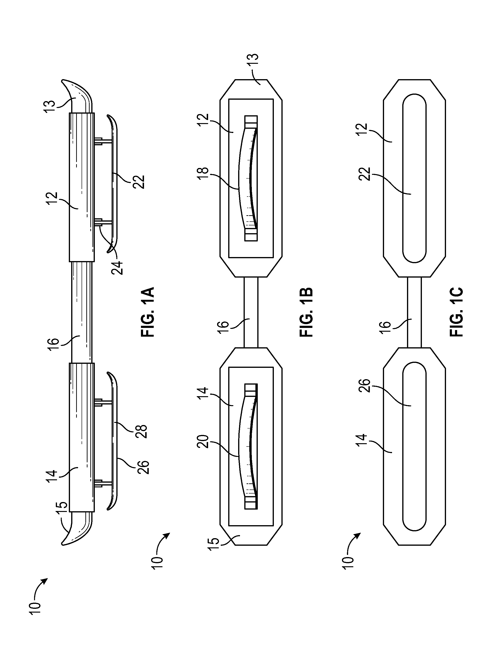
FIGS. 1A, 1B and 1C illustrate a side view, a top view and a bottom view, respectively of an apparatus 10 for gliding over snow, in accordance with one embodiment of the present disclosure.
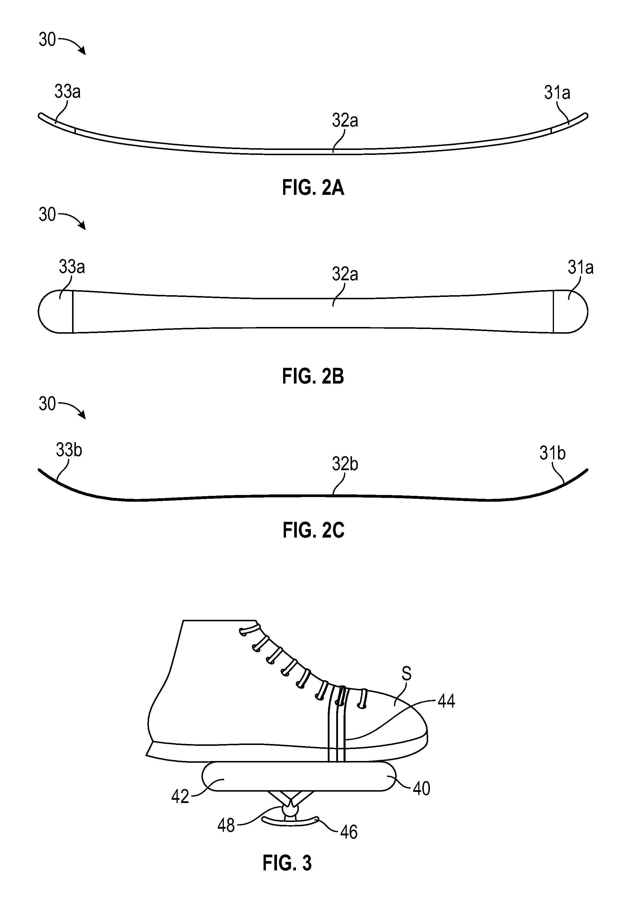
FIGS. 2A, 2B and 2C illustrates a board 30 such a ski board, in accordance with one embodiment of the present disclosure.
FIG. 3 illustrates a side view of an apparatus 40 comprising a deck 42 and a board 46 coupled via a connector 48, in accordance with one embodiment of the present disclosure.
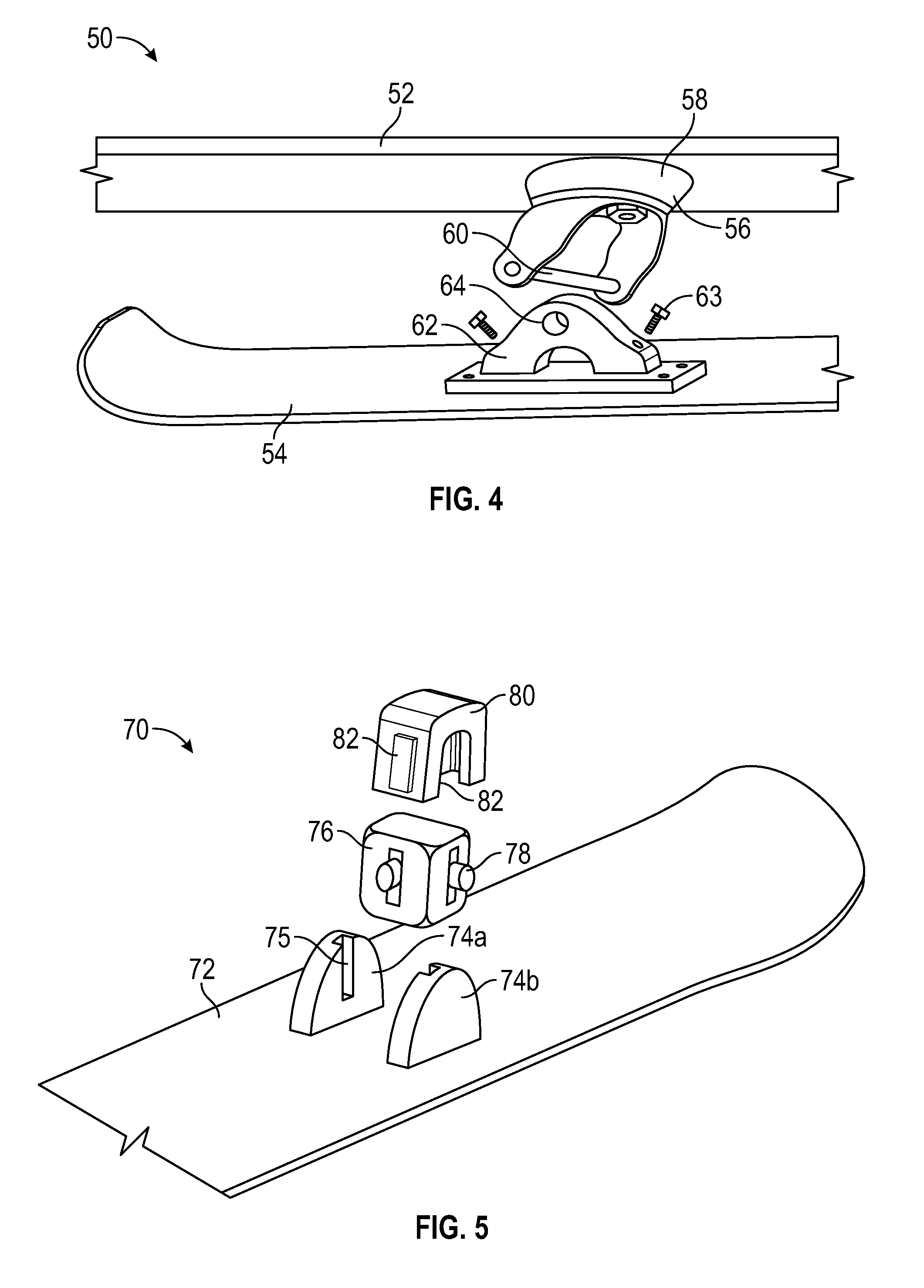
FIG. 4 illustrates a perspective view of an apparatus 50 for gliding over snow, in accordance with one exemplary embodiment of the present disclosure.
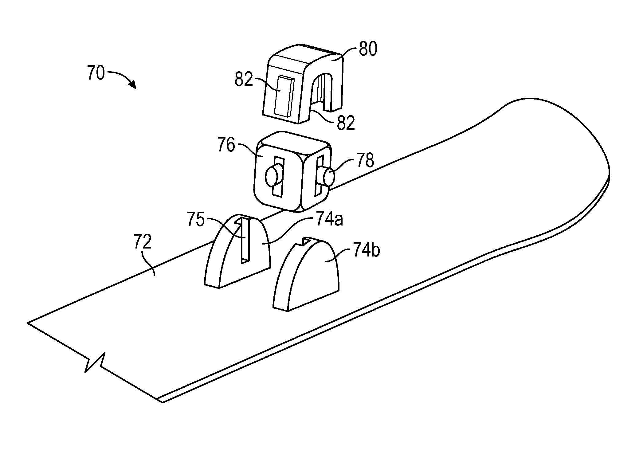
FIG. 5 illustrates a perspective view of a connector 70 coupled to a board 72, in accordance with one exemplary embodiment of the present disclosure.
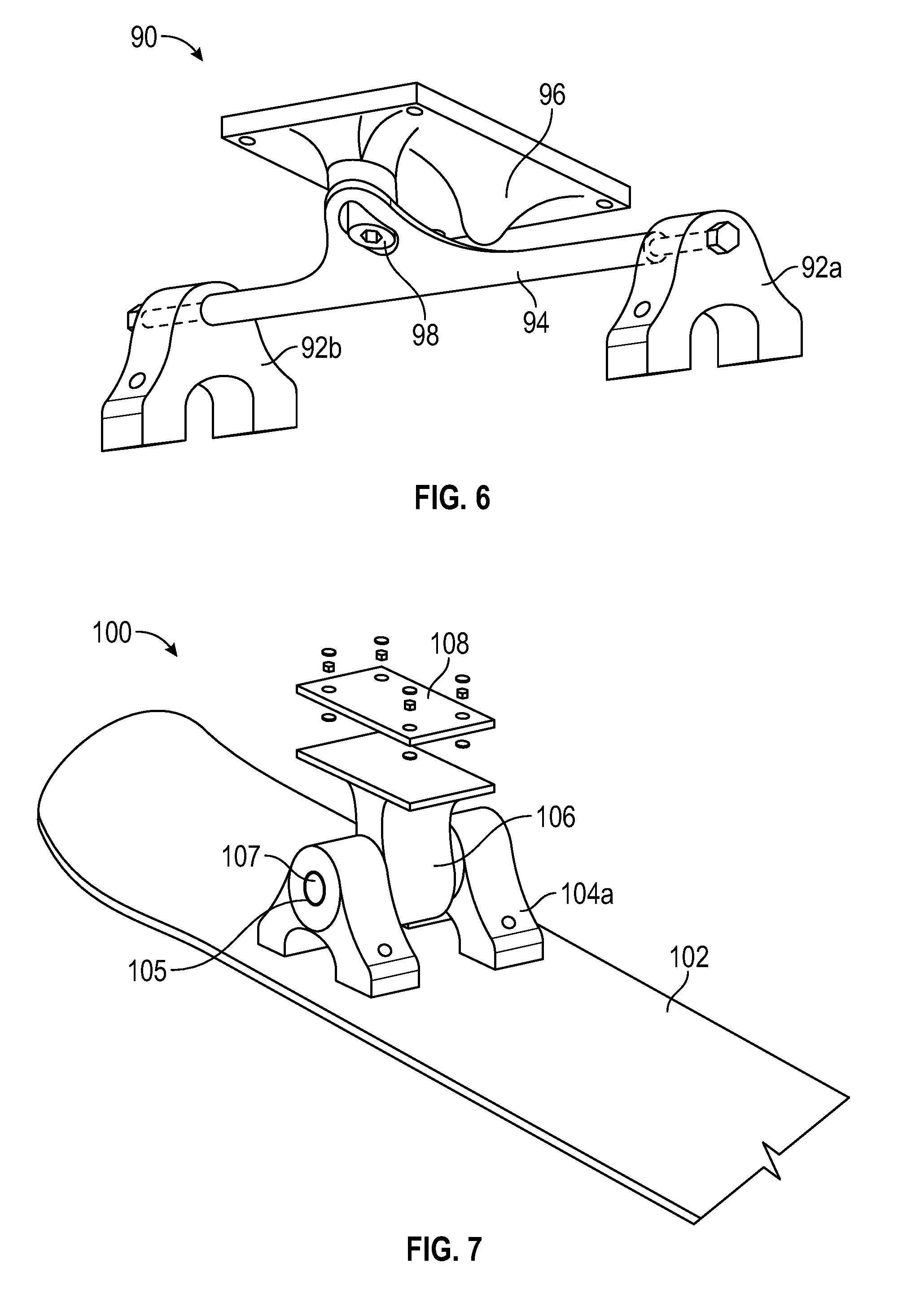
FIG. 6 illustrates a perspective view of a connector 90, in accordance with one exemplary embodiment of the present disclosure.
FIG. 7 illustrates a perspective view of a connector 100, in accordance with one exemplary embodiment of the present disclosure.
FIG. 8 illustrates a perspective view of an apparatus 120 for gliding over snow, in accordance with one exemplary embodiment of the present disclosure.
FIGS. 9A and 9B illustrate an apparatus 150 for gliding over snow comprising a toggle 158 at a swivel arm 156, in accordance with one embodiment of the present disclosure.
DETAILED DESCRIPTION OF THE EMBODIMENTS OF THE INVENTION
The following detailed description is intended to provide example implementations to one of ordinary skill in the art, and is not intended to limit the invention to the explicit disclosure, as one or ordinary skill in the art will understand that variations can be substituted that are within the scope of the invention as described.
The present disclosure discloses an apparatus for gliding over snow. The apparatus comprises at least two decks i.e., a first deck and a second deck coupled via a swivel arm. Each deck e.g., the first deck comprises a strap to receive foot of a user. The apparatus comprises a board coupled to the deck via a connector. For example, the first deck comprises a first board, and a second deck comprises a second board. The connector is used to transfer the load put on the deck to the board to create forward momentum. The user stands on the decks with his two feet and creates a swivel-motion with the help of the swivel arm. The swivel-motion is transferred to the connector and then to the board to create forward momentum. The board then glides over the snow.
Various features and embodiments of an apparatus for gliding over snow are explained in conjunction with the description of FIGS. 1A-9B.
Referring to FIGS. 1A, 1B and 1C, a front view, a top view and a bottom view, respectively of an apparatus 10 for gliding over snow is shown, in accordance with one embodiment of the present disclosure. The apparatus 10 comprises a first deck 12 and a second deck 14. Each of the first deck 12 and the second deck 14 is made of plastic, fiberglass, wood and so on. The first deck 12 and the second deck 14 are provided in a flat or concave structure such that a user may keep one foot on the first deck 12 and another foot on the second deck 14. The first deck 12 comprises a first tip 13 at farther end. Similarly, the second deck 14 comprises a second tip 15 at farther end. As can be seen in at least FIGS. 1A and 1B, the first deck 12 and the second deck 14 are connected using a swivel arm 16. As can be seen, the swivel arm 16 is provided at center of the first deck 12 and the second deck 14. It should be understood that when the user stands on the first deck 12 and the second deck 14 (by keeping one foot on first deck 12 and the second deck 14), the user can create a swivel motion i.e., S-motion. Further, the swivel arm 16 facilitates in grinding on hand or box rails. As such, the swivel arm 16 enables the user to provide different motions to glide in different ways.
As can be seen from FIG. 1B, the first deck 12 comprises a first strap 18. Similarly, the second deck 14 comprises a second strap 20. The first strap 18 and the second strap 20 are used to receive the foot e.g., right foot is received at the first strap 18 and the left foot is received at the second strap 20. The first strap 18 and the second strap 20 are provided with locks (not shown) to hold the foot of the user or to release the foot when not in use. The first strap 18 and the second strap 20 are adjustable, and can lock in place such that the users having different foot or shoe size can use the apparatus 10 for gliding over snow.
Referring to FIG. 1A, the apparatus 10 further comprises a first board 22 coupled to the first deck 12 using a first connector 24. Further, the apparatus 10 further comprises a second board 26 coupled to the second deck 14 using a second connector 28. The first board 22 and the second board 26 may include a ski board, snowboard and so on.
Referring to FIGS. 2A and 2B, a side view and top view of a first board 30 (similar to the first board 22 in FIG. 1A) is shown, in accordance with one embodiment of the present disclosure. The first board 30 comprises a first end 31a, a center 32a and second end 33a. As can be seen from FIG. 2A, the first end 31a and the second end 33a are raised at an angle as compared to the center 32a. The first end 31a and the second end 33a are raised low to provide steering, pivoting and carving when the first board 30 is used to glide over snow. Specifically, at slow speeds, due to the (lower) raised angle of the first end 31a and the second end 33a, contact length of the first board 30 with snow is reduced thereby facilitating steering and pivoting easily. Further, at medium speeds, the first end 31a and the second end 33a engagement with the snow is quicker and results in quick steering and carving. Furthermore, the first end 31a and the second end 33a may be raised higher such that the edge length and the side cut are enhanced to increase carving, grip and stability for the first board 30. Similar, the second board (not shown) is also provided with ends raised when compared with its center.
In another example, the first board 30 is provided in the shape shown in FIG. 2C. As can be seen, the first board 30 comprises a first end 31b, a center 32b and a second end 33b. In the current example, the first end 31b and the second end 33b are raised at an angle. Further, the center 32b is raised in convex shape. The first board 30 facilitates in gliding on snow in all conditions. For instance, the first board 30 can be used to float or ski or glide over powder surfaces and gives ability to turn on packed snow. This is because; due to raised shape at the first end 31b, the center 32b and the second end 33b, overall surface of the first board 30 comes in contact with the snow when weight is put onto the first board 30. As a result, the first end 31b and the second end 33b of the first board 30 don't get buried in the snow and the first board 30 remains above the surface (powder surface) and allows the user to ride easily. Further, the first board 30 allows the user to take sharp and easy turns.
As explained above, the first deck is coupled to the first board using the first connector. Referring to FIG. 3, a side view of an apparatus 40 used for gliding over snow is shown, in accordance with one embodiment of the present disclosure. The apparatus 40 comprises a first deck 42. The first deck 42 comprises a strap 44 used to strap boot or shoe S of the user. The first deck 42 is coupled to a first board 46 using a first connector 48. It should be understood that the user might place one foot on the first deck 42 and another foot on a second deck (not shown). In order to create forward momentum, the pressure exerted (swivel motion or S-motion) on the first deck 42 needs to be transferred onto the first board 46 for gliding over snow. As such, the first connector 48 plays an important role in transferring the swivel motion applied on the first deck 42 to the first board 46.
Referring to FIG. 4, a perspective view of an apparatus 50 is shown. The apparatus 50 comprises a deck 52, a board 54 and a connector 56. The connector 56 comprises a first section 58 coupled to the deck 52 at underside. In one example, the first section 58 is provided as a caster at an angle of 45 degrees. It should be understood that the first section 58 allows having 360-degree spinning motion due to its pivot caster position. The first section 58 comprises a connecting rod 60. Further, the connector 56 comprises a second section 62 coupled to the board 54. In one implementation, the second section 62 is coupled to the board 54 using screws 63. The second section 62 comprises a hole 64 to receive the connecting rod 60.
In use, when the user stands on the deck 52, the user may apply pressure in swivel motion on the deck 52 to create forward momentum. As a consequence, the first section 58 wields spinning motion based on the amount of the pressure exerted on the deck 52. The spinning motion is transferred to the second section 62 via the connecting rod 60 and the board 54 moves forward. As the first section 58 facilitates in 360 degree spinning motion, the apparatus 50 is used to glide in any angle with ease.
Referring to FIG. 5, a perspective view of a connector 70 coupled to a board 72 is shown, in accordance with one exemplary embodiment of the present disclosure. The connector 70 comprises at least two first sections 74a and 74b protruding away from the surface of the board 72. Each of the two first sections 74a and 74b are provided with a first cut section 75. The first cut section 75 is provided in perpendicular to the board 72. The connector 70 further comprises a second section 76 provided in a square shape. The second section 76 comprises fins 78 protruding out from mid-section at each side face of the second section 76. In other words, the second section 76 comprises fins 78 provided at four sides. Each of the fins 78 is projecting outwards from the second section 76. Further, the connector 70 comprises a third section 80 provided in U-shape. The third section 80 comprises a plurality of second cut sections 82 provided at interior surface of the third section 80. Each of the second cut sections 82 is provided in perpendicular to the board 72. It should be understood that upper end of the U-shaped third section 80 is coupled to the underside of the deck (not shown, similar to the first deck 12 in FIG. 1A).
At first, two fins 78 of the second section 76 are placed in the first cut section 75 provided in the first sections 74a and 74b. Subsequently, two fins 78 of the second section 76 are placed in the second cut sections 82 provided in the third section 80. In use, when the user stands on the deck, swivel motion created by the user is transferred to the third section 80. The third section 80 transfers the swivel motion to the second section 76, then to the first sections 74a and 74b and then to the board 72. The third section 80 allows the second section 76 to pivot in left and right direction and the first sections 74a and 74b allow the second section 76 to pivot in front and back direction. As a result, user can swivel in any angle or direction on the deck to create forward momentum at the board 72.
Referring to FIG. 6, a perspective view of connector 90 is shown, in accordance with one exemplary embodiment of the present disclosure. The connector 90 can be used with the apparatus shown in FIGS. 1A, and 3. The connector 90 comprises at least two first sections 92a and 92b. In one implementation, the first sections 92a and 92b are coupled to the board (not shown, similar to the first board 22 in FIG. 1A). The first sections 92a and 92b are coupled using a second section 94. Further, the second section 94 is coupled to a third section 96 via a link 98. It should be understood that the third section 96 is coupled to a deck (not shown, similar to the first deck 12 in FIG. 1A) at underside. In use, the user may exert swivel motion by standing on the deck. The swivel motion or pressure is received at the third section 96 and it is transferred to the board (not shown) via the second section 94 and the first sections 92a and 92b.
Referring to FIG. 7, a perspective view of a connector 100 coupled to a board 102 is shown, in accordance with one exemplary embodiment of the present disclosure. The connector 100 comprises at least two first sections 104a and 104b protruding away from the surface of the board 102. The first sections 104a and 104b comprises a hole 105. The connector 100 further comprises a second section 106 having a connecting rod 107. The connecting rod 107 is placed inside the hole 105 to couple the first sections 104a and 104b with the second section 106. The second section comprises a plate 108 used to couple the second section 106 to a deck (not shown, similar to the first deck 12 in FIG. 1A). In use, the user may exert pressure by standing on the deck. The pressure is received at the second section 106 is transferred to the board 102 via the first sections 104a and 104b.
Referring to FIG. 8, a perspective of an apparatus 120 is shown, in accordance with one embodiment of the present disclosure. The apparatus 120 comprises a deck 122 provided in a flat structure. The deck 122 comprises a strap 124 to receive shoe or foot of the user. The deck 122 is coupled to a board 126 via a connector 130. The connector 130 comprises a first section 132 provided in a V-shape. Open ends of the first section 132 are coupled to the deck 122 at underside of the deck 122. Further, the connector 130 comprises a plurality of second sections 134a and 134b. The second sections 134a and 134b are coupled to the board 126. The second sections 134a and 134b comprises a hole 135. The first section 132 and the second sections 134a and 134b are coupled by placing a connecting rod 136 in the hole 135. In use, the user may exert pressure (swivel motion) by standing on the deck 122. The pressure is received at the first section 132 is transferred to the board 126 via the second sections 134a and 134b. It should be understood that the connector 130 is used to transfer the swivel motion created on the deck 122 to the board 126 such that the forward momentum is created at the board 126 and the apparatus 120 moves in the forward direction.
In one implementation, the apparatus described above can be folded and carried from one place to another. Referring to FIGS. 9A and 9B, an apparatus 150 for gliding over snow is shown. The apparatus 150 comprises a first deck 152 and a second deck 154. The first deck 152 and the second deck 154 are coupled via a swivel arm 156. In accordance with the current embodiment, the swivel arm 156 is provided with a toggle 158 at its length, preferably at its center. The toggle 158 is operated to fold the apparatus 150. Specifically, the toggle 158 is operated such that when folded, the first deck 152 sits on top of the second deck 154 as shown in FIG. 9B. After folding, the length of the apparatus 150 reduces and it becomes easy to carry the apparatus 150 from one place to another.
It can be understood from the above description that novice users can use the apparatus. The users can stand on the two decks and tighten the straps. In order to glide e.g., glide on a downhill or terrain; the user can create a swivel motion using the foot with the help of the swivel arm. The swivel motion is transferred to the board via the connector. The swivel motion transferred to the board creates a forward momentum and the user will be able to glide over snow. The above disclosure makes it easier for users to glide or carve with ease. The users may tighten their foot or shoe on the deck by adjusting the length of the strap.
Further, it is to be understood that the apparatus may be provided in various shapes and sizes. For example, the shape of the decks may be provided in square, rectangular or any other shape. The length of the swivel arm can be provided based on need and terrain used for gliding. Further, the length and shape of the board may be chosen as may be needed. The obvious variants of the components disclosed above are considered to be within scope of the current disclosure.
The foregoing description conveys the best understanding of the objectives and advantages of the present invention. Different embodiments may be made of the inventive concept of this invention. It is to be understood that all matter disclosed herein is to be interpreted merely as illustrative, and not in a limiting sense.
* * * * *
D00000
D00001
D00002
D00003
D00004
D00005
XML
uspto.report is an independent third-party trademark research tool that is not affiliated, endorsed, or sponsored by the United States Patent and Trademark Office (USPTO) or any other governmental organization. The information provided by uspto.report is based on publicly available data at the time of writing and is intended for informational purposes only.
While we strive to provide accurate and up-to-date information, we do not guarantee the accuracy, completeness, reliability, or suitability of the information displayed on this site. The use of this site is at your own risk. Any reliance you place on such information is therefore strictly at your own risk.
All official trademark data, including owner information, should be verified by visiting the official USPTO website at www.uspto.gov. This site is not intended to replace professional legal advice and should not be used as a substitute for consulting with a legal professional who is knowledgeable about trademark law.