Wireless shunts with storage
Kassem
U.S. patent number 10,265,509 [Application Number 13/848,295] was granted by the patent office on 2019-04-23 for wireless shunts with storage. This patent grant is currently assigned to INTEGRA LIFESCIENCES SWITZERLAND SARL. The grantee listed for this patent is DePuy Synthes Products, LLC. Invention is credited to Salim Kassem.


| United States Patent | 10,265,509 |
| Kassem | April 23, 2019 |
Wireless shunts with storage
Abstract
Devices and methods useful for storing and retrieving information related to a medical device such as an implantable valve or an implantable sensor are disclosed. An implantable valve can include a valve housing adapted to receive fluid flow therethrough between a valve inlet and a valve outlet. A valve assembly can be disposed within the valve housing and adapted to control a rate of fluid flowing through the valve housing. The implantable valve can also include a radio frequency identification (RFID) tag associated with the valve housing, adapted to store data, and including an antenna for communicating stored data to an external reading device. The RFID tag can store data related to, for example, a patient, a pressure setting of the valve assembly, and/or pressure sensor disposed within the valve. The RFID tag can also store an identifier that identifies the implantable valve, a pressure sensor disposed in the valve housing, a patient associated with the implantable valve, and/or patient clinical history.
| Inventors: | Kassem; Salim (North Attleboro, MA) | ||||||||||
|---|---|---|---|---|---|---|---|---|---|---|---|
| Applicant: |
|
||||||||||
| Assignee: | INTEGRA LIFESCIENCES SWITZERLAND
SARL (Le Locle, CH) |
||||||||||
| Family ID: | 40293654 | ||||||||||
| Appl. No.: | 13/848,295 | ||||||||||
| Filed: | March 21, 2013 |
Prior Publication Data
| Document Identifier | Publication Date | |
|---|---|---|
| US 20130226068 A1 | Aug 29, 2013 | |
Related U.S. Patent Documents
| Application Number | Filing Date | Patent Number | Issue Date | ||
|---|---|---|---|---|---|
| 11931187 | Oct 31, 2007 | 8480612 | |||
| Current U.S. Class: | 1/1 |
| Current CPC Class: | A61B 5/031 (20130101); A61M 39/22 (20130101); A61B 5/0031 (20130101); A61M 27/002 (20130101); A61M 27/006 (20130101); A61M 2205/3523 (20130101); A61M 2205/3344 (20130101); A61M 2205/52 (20130101); A61M 2205/04 (20130101); A61M 2205/32 (20130101); A61M 2205/3331 (20130101) |
| Current International Class: | A61M 5/00 (20060101); A61B 5/03 (20060101); A61B 5/00 (20060101); A61M 27/00 (20060101); A61M 39/22 (20060101) |
| Field of Search: | ;604/7-10,228 ;600/488 ;251/65,177,228 ;137/530,531 |
References Cited [Referenced By]
U.S. Patent Documents
| 2396351 | March 1946 | Thompson |
| 3886948 | June 1975 | Hakim |
| 3960142 | June 1976 | Elliott et al. |
| 3976278 | August 1976 | Dye et al. |
| 4077882 | March 1978 | Gangemi |
| 4114603 | September 1978 | Wilkinson |
| 4127110 | November 1978 | Bullara |
| 4135509 | January 1979 | Shannon |
| 4237900 | December 1980 | Schulman et al. |
| 4332255 | June 1982 | Hakim et al. |
| 4385636 | May 1983 | Cosman |
| 4387715 | June 1983 | Hakim et al. |
| 4421124 | December 1983 | Marshall |
| 4494950 | January 1985 | Fischell |
| 4540400 | September 1985 | Hooven |
| 4551128 | November 1985 | Hakim et al. |
| 4556086 | December 1985 | Raines |
| 4576181 | March 1986 | Wallace et al. |
| 4593703 | June 1986 | Cosman |
| 4595390 | June 1986 | Hakim et al. |
| 4611578 | September 1986 | Heimes |
| 4615691 | October 1986 | Hakim et al. |
| 4625730 | December 1986 | Fountain et al. |
| 4660568 | April 1987 | Cosman |
| 4676772 | June 1987 | Hooven |
| 4711249 | December 1987 | Brooks |
| 4718425 | January 1988 | Tanaka et al. |
| 4723556 | February 1988 | Sussman |
| 4727887 | March 1988 | Haber |
| 4772257 | September 1988 | Hakim et al. |
| 4785822 | November 1988 | Wallace |
| 4787886 | November 1988 | Cosman |
| 4820265 | April 1989 | DeSatnick et al. |
| 4841977 | June 1989 | Griffith et al. |
| 4850358 | July 1989 | Millar |
| 4885002 | December 1989 | Watanabe et al. |
| 4893630 | January 1990 | Bray, Jr. |
| 5004472 | April 1991 | Wallace |
| 5009662 | April 1991 | Wallace et al. |
| 5021046 | June 1991 | Wallace |
| 5163904 | November 1992 | Lampropoulos et al. |
| 5201753 | April 1993 | Lampropoulos et al. |
| 5252962 | October 1993 | Urbas et al. |
| 5265606 | November 1993 | Kujawski |
| 5280789 | January 1994 | Potts |
| 5321989 | June 1994 | Zimmer et al. |
| 5337612 | August 1994 | Evans |
| 5385514 | January 1995 | Dawe |
| 5396899 | March 1995 | Strittmatter |
| 5417235 | May 1995 | Wise et al. |
| 5425713 | June 1995 | Taylor et al. |
| 5431057 | July 1995 | Zimmer et al. |
| 5431629 | July 1995 | Lampropoulos et al. |
| 5437627 | August 1995 | Lecuyer |
| 5449345 | September 1995 | Taylor et al. |
| 5490514 | February 1996 | Rosenberg |
| 5591171 | January 1997 | Brown |
| 5622869 | April 1997 | Lewis et al. |
| 5630836 | May 1997 | Prem et al. |
| 5643194 | July 1997 | Negre |
| 5651767 | July 1997 | Schulman et al. |
| 5704352 | January 1998 | Tremblay et al. |
| 5711302 | January 1998 | Lampropoulos et al. |
| 5716342 | February 1998 | Dumbraveanu et al. |
| 5721382 | February 1998 | Kriesel et al. |
| 5797403 | August 1998 | DiLorenzo |
| 5803917 | September 1998 | Butterfield et al. |
| 5836886 | November 1998 | Itoigawa et al. |
| 5873840 | February 1999 | Neff |
| 5928182 | July 1999 | Kraus et al. |
| 5935083 | August 1999 | Williams |
| 5970801 | October 1999 | Ciobanu et al. |
| 5993395 | November 1999 | Shulze |
| 5993398 | November 1999 | Alperin |
| 6010482 | January 2000 | Kriesel et al. |
| 6025725 | February 2000 | Gershenfeld et al. |
| 6071267 | June 2000 | Zamierowski |
| 6083174 | July 2000 | Brehmeier-Flick et al. |
| 6111520 | August 2000 | Allen et al. |
| 6113553 | September 2000 | Chubbuck |
| 6120457 | September 2000 | Coombes et al. |
| 6158965 | December 2000 | Butterfield et al. |
| 6171252 | January 2001 | Roberts |
| 6208254 | March 2001 | McQueen et al. |
| 6248080 | June 2001 | Miesel et al. |
| 6264612 | July 2001 | McConnell et al. |
| 6278379 | August 2001 | Allen et al. |
| 6316522 | November 2001 | Loomis et al. |
| 6371976 | April 2002 | Vrzalik et al. |
| 6416291 | July 2002 | Butterfield et al. |
| 6439538 | August 2002 | Ito |
| 6447449 | September 2002 | Fleischman et al. |
| 6470213 | October 2002 | Alley |
| 6481292 | November 2002 | Reich |
| 6503208 | January 2003 | Skovlund et al. |
| 6533733 | March 2003 | Ericson et al. |
| 6537232 | March 2003 | Kucharczyk et al. |
| 6589189 | July 2003 | Meyerson et al. |
| 6626902 | September 2003 | Kucharczyk et al. |
| 6636769 | October 2003 | Govari et al. |
| 6682490 | January 2004 | Roy et al. |
| 6724310 | April 2004 | Gershenfeld et al. |
| 6731976 | May 2004 | Penn et al. |
| 6770030 | August 2004 | Schaupp et al. |
| 6796942 | September 2004 | Kreiner et al. |
| 6855115 | February 2005 | Fonseca et al. |
| 6891474 | May 2005 | Fletcher |
| 6974422 | December 2005 | Millar |
| 7147604 | December 2006 | Allen et al. |
| 7435229 | October 2008 | Wolf |
| 7485105 | February 2009 | Wolf |
| 7842004 | November 2010 | Kassem |
| 2002/0035331 | March 2002 | Brockway et al. |
| 2002/0038072 | March 2002 | Muller et al. |
| 2002/0052563 | May 2002 | Penn et al. |
| 2002/0077553 | June 2002 | Govari et al. |
| 2002/0087059 | July 2002 | O'keefe |
| 2002/0099428 | July 2002 | Kaufman |
| 2002/0151770 | October 2002 | Noll et al. |
| 2003/0023134 | January 2003 | Tracey |
| 2003/0032915 | February 2003 | Saul |
| 2003/0135110 | July 2003 | Leussler |
| 2003/0216666 | November 2003 | Ericson et al. |
| 2004/0073137 | April 2004 | Lloyd et al. |
| 2004/0134991 | July 2004 | Fletcher et al. |
| 2004/0147871 | July 2004 | Burnett |
| 2004/0193021 | September 2004 | Zdeblick et al. |
| 2004/0260229 | December 2004 | Meir |
| 2005/0027330 | February 2005 | Govari |
| 2005/0043669 | February 2005 | Rosenberg |
| 2005/0043670 | February 2005 | Rosenberg |
| 2005/0165317 | July 2005 | Turner et al. |
| 2005/0187487 | August 2005 | Azizkhan et al. |
| 2005/0187488 | August 2005 | Wolf |
| 2005/0187509 | August 2005 | Wolf |
| 2005/0197585 | September 2005 | Brockway et al. |
| 2005/0204811 | September 2005 | Neff |
| 2005/0247319 | November 2005 | Berger |
| 2005/0277839 | December 2005 | Alderman et al. |
| 2006/0009699 | January 2006 | Roteliuk et al. |
| 2006/0020239 | January 2006 | Geiger et al. |
| 2006/0036208 | February 2006 | Burnett |
| 2006/0149161 | July 2006 | Wilson et al. |
| 2006/0189888 | August 2006 | Hassler et al. |
| 2006/0195043 | August 2006 | Rutherford et al. |
| 2006/0211944 | September 2006 | Mauge et al. |
| 2006/0211945 | September 2006 | Mauge et al. |
| 2006/0211946 | September 2006 | Mauge et al. |
| 2006/0212439 | September 2006 | Field |
| 2006/0235310 | October 2006 | O'Brien et al. |
| 2006/0283007 | December 2006 | Cros et al. |
| 2007/0049845 | March 2007 | Fleischman et al. |
| 2007/0118038 | May 2007 | Bodecker et al. |
| 2007/0167867 | July 2007 | Wolf |
| 2007/0208293 | September 2007 | Mansour et al. |
| 2007/0210923 | September 2007 | Butler et al. |
| 2007/0252691 | November 2007 | Mirmobin et al. |
| 2007/0282210 | December 2007 | Stern |
| 2008/0058652 | March 2008 | Payne |
| 2008/0065646 | March 2008 | Zhang |
| 2008/0139959 | June 2008 | Miethke et al. |
| 2008/0208083 | August 2008 | Lin et al. |
| 2008/0242944 | October 2008 | Sharma |
| 2009/0107233 | April 2009 | Kassem |
| 2009/0112103 | April 2009 | Kassem |
| 2009/0112147 | April 2009 | Kassem |
| 2009/0112308 | April 2009 | Kassem |
| 2010/0168673 | July 2010 | Stergiopulos et al. |
| 2011/0040233 | February 2011 | Kassem |
| 729467 | Feb 2001 | AU | |||
| 2555770 | Jun 2003 | CN | |||
| 4042335 | Aug 1991 | DE | |||
| 4042336 | Aug 1991 | DE | |||
| 0115548 | Aug 1984 | EP | |||
| 0619101 | Oct 1994 | EP | |||
| 1312302 | May 2003 | EP | |||
| 1389477 | Feb 2004 | EP | |||
| 1491137 | Dec 2004 | EP | |||
| 1738792 | Jan 2007 | EP | |||
| 02-003821 | Jan 1990 | JP | |||
| 91/105575 | May 1991 | WO | |||
| 99/53990 | Oct 1999 | WO | |||
| 01/021066 | Mar 2001 | WO | |||
| 2005/046467 | May 2005 | WO | |||
| 2006/048664 | May 2006 | WO | |||
| 2006117123 | Nov 2006 | WO | |||
| 2007/041843 | Apr 2007 | WO | |||
| 2007081741 | Jul 2007 | WO | |||
Other References
|
[No Author Listed] Surface Micromachined Pressure Sensor Technologies, product data sheet of Institut Mikroelektronische Schaultungen und Systeme, pp. 1-2, Sep. 2002. cited by applicant . [No Author Listed] User's Manual HD2114.0-HD2134.0, HD2164.0-HD2114B.0, HD2114, 2-HD2134.2, HD2164.2-HD2114B.2; Rev. 1.0, Delta OHM, Via g. Marconi, 5-35020 Caselle Di Selvazzano (PD)--Italy, pp. 2-6 (2004). cited by applicant . [No Author Listed] Telemetric Integrated Pressure Sensors, product data sheet of Institut Mikroelektronische Schaultungen und Systeme, p. 1, Sep. 2002. cited by applicant . Dobkin et al., "A Radio-Oriented Introduction to RFID-Protocols, Tags and Applications," High Frequency Electronics, 32-46 (2005). cited by applicant . Ekstedt, J., "CSFS Hydrodynamic Studies in Man, 1. Method of Constant Pressure CSF Infusion," J. Neurology, Neurosurgery & Psych.40:105-19 (1977). cited by applicant . European Search Report, Appl. No. 052580800.0, dated May 15, 2006. cited by applicant . European Search Report, EP Application No. 08253545.1-1526, dated Mar. 5, 2009. cited by applicant . European Search Report, EP Application No. 08253554, dated Feb. 19, 2009. cited by applicant . Ko WH et al: "Cerebrospinal Fluid Control System," Proceeding of the IEEE, IEEE. New York, US, vol. 76, No. 9, Sep. 1, 1988 (Sep. 1, 1988), pp. 1226-1235, XP000094517 ISSN: 0018-9219. cited by applicant . Kroin, JS, et al., "Long-term testing of an intracranial pressure monitoring device", J. Neurosurg, V. 93, pp. 852-858, 2000. cited by applicant . Sensor Transponder for Pressure and Temperature, data sheet of Institut Mikroelektronische Schaultungen und Systeme, pp. 1-2, Feb. 2000. cited by applicant . Shapiro, K. et al. "Characterization of Clinical CSF Dynamics and Neural Zxis Compliance Using the Pressure-Volume Index: 1. The Normal Pressure-Volume Index," Annals of Neurology, 7(6):508-14 (1980). cited by applicant . U.S. Office Action for U.S. Appl. No. 12/913,054 dated Nov. 26, 2012 (11 Pages). cited by applicant . U.S. Office Action for U.S. Appl. No. 11/931,041 (Publication No. US-2009-0107233-A1) dated Dec. 30, 2009, 19 pages. cited by applicant . U.S. Office Action for U.S. Appl. No. 11/931,127 dated May 10, 2012 (26 Pages). cited by applicant . U.S. Office Action for U.S. Appl. No. 11/931,151 dated Feb. 6, 2012. cited by applicant . U.S. Office Action for U.S. Appl. No. 11/931,151 dated Jul. 13, 2012 (23 pages). cited by applicant . U.S. Office Action for U.S. Appl. No. 11/931,151 dated Jul. 19, 2011, 23 pages. cited by applicant . U.S. Office Action for U.S. Appl. No. 11/931,151 dated Feb. 20, 2013, 25 pages. cited by applicant . U.S. Office Action for U.S. Appl. No. 11/931,187 dated Apr. 24, 2012 (10 Pages). cited by applicant . U.S. Office Action for U.S. Appl. No. 11/931,187 dated May 11, 2010, 8 pages. cited by applicant . U.S. Office Action for U.S. Appl. No. 11/931,187 dated May 9, 2011, 7 pages. cited by applicant . U.S. Office Action for U.S. Appl. No. 11/931,187 dated Oct. 31, 2011. cited by applicant . U.S. Office Action for U.S. Appl. No. 11/931,187 dated Oct. 6, 2010, 8 pages. cited by applicant . U.S. Office Action for U.S. Appl. No. 11/931,151 dated May 15, 2013, 21 pages. cited by applicant. |
Primary Examiner: Zimbouski; Ariana
Attorney, Agent or Firm: Mintz Levin Cohn Ferris Glovsky and Popeo, P.C.
Parent Case Text
CROSS REFERENCE TO RELATED APPLICATIONS
The present application is a divisional of U.S. patent application Ser. No. 11/931,187, filed on Oct. 31, 2007 and entitled "Wireless Shunts with Storage," which is hereby incorporated by reference in its entirety.
Claims
What is claimed is:
1. A method, comprising: positioning a distal end of a ventricular catheter within a ventricle; coupling a proximal end of the ventricular catheter to a valve inlet formed on an implantable valve, and coupling a valve outlet formed on the valve to a drainage catheter such that fluid flows from the ventricle through the valve to the drainage catheter; and using an external reading device to obtain first data telemetrically from a pressure sensor disposed in the valve and including a first antenna, and to obtain second data telemetrically from a radio frequency identification tag disposed in the valve as a physically separate component from the pressure sensor, the radio frequency identification tag including a second antenna, and the first data being indicative of a pressure measurement obtained by the pressure sensor, and the second data including non-pressure measurement data.
2. The method of claim 1, wherein the radio frequency identification tag stores calibration data for calibrating pressure measured by the pressure sensor.
3. The method of claim 1, wherein the radio frequency identification tag stores data related to a patient medical history.
4. The method of claim 1, wherein the radio frequency identification tag is associated with a second sensor and stores data related to the second sensor.
5. The method of claim 1, further comprising adjusting a rate of fluid flow from the valve inlet to the valve outlet.
6. The method of claim 1, wherein the radio frequency identification tag stores a pressure measurement obtained by the pressure sensor disposed within the valve.
7. The method of claim 6, further comprising communicating with the pressure sensor and the radio frequency identification tag at a same frequency using the external reading device.
8. The method of claim 1, further comprising obtaining stored data telemetrically from the radio frequency identification tag by positioning the external reading device in proximity to the radio frequency identification tag.
9. The method of claim 1, further comprising programming the radio frequency identification tag with the external reading device.
10. The method of claim 1, wherein obtaining the second data includes obtaining data related to any of calibration data for the pressure sensor, patient data, patient clinical history, identification data for the valve, and identification data for the pressure sensor disposed within the valve.
11. The method of claim 1, wherein the second data includes at least one of data identifying the valve, data identifying a type of the valve, data indicative of a sensed parameter other than pressure, data identifying a patient in which the valve is implanted, data identifying the pressure sensor, data indicative of a medical history of a patient in which the valve is implanted, and drift compensation data for the pressure sensor.
12. The method of claim 1, wherein the second data includes calibration data for the pressure sensor, and the method further comprises using the obtained calibration data to telemetrically calibrate the pressure sensor.
13. The method of claim 1, further comprising implanting a second pressure sensor at a location outside the implantable valve; and using the external reading device to obtain second data telemetrically from the radio frequency identification tag, the second data being indicative of a pressure measurement obtained by the second pressure sensor.
14. The method of claim 1, wherein the external reading device includes a single external reading device that obtains the first data and the second data.
15. The method of claim 1, wherein the external reading device includes a first external reading device that obtains the first data and a second external reading device that obtains the second data.
16. A method, comprising: implanting a valve in a patient such that a proximal end of a ventricular catheter is coupled to a valve inlet of the valve, a distal end of the ventricular catheter is positioned within a ventricle of the patient, and a valve outlet of the implanted valve is coupled to a drainage catheter such that fluid flows from the ventricle through the valve to the drainage catheter; wherein a pressure sensor including a first antenna is disposed in the implanted valve, the pressure sensor being configured to communicate first data telemetrically to an external reading device using the first antenna, the first data being indicative of a pressure measurement obtained by the pressure sensor; and wherein a radio frequency identification tag including a second antenna is disposed in the implanted valve, the radio frequency identification tag being a physically separate component from the pressure sensor, the radio frequency identification tag being configured to communicate second data telemetrically to the external reading device using the second antenna, the second data including non-pressure measurement data.
17. A method, comprising: implanting a valve in a patient such that a proximal end of a ventricular catheter is coupled to a valve inlet of the valve, a distal end of the ventricular catheter is positioned within a ventricle of the patient, and a valve outlet of the implanted valve is coupled to a drainage catheter such that fluid flows from the ventricle through the valve to the drainage catheter, the valve including a first pressure sensor disposed therein; and implanting a second pressure sensor at a location external to the implanted valve; wherein a radio frequency identification tag is disposed in the implanted valve, the radio frequency identification tag being configured to telemetrically communicate first data indicative of pressure sensed by the first pressure sensor to an external reading device, and being configured to telemetrically communicate second data indicative of pressure sensed by the second pressure sensor telemetrically to the external reading device.
Description
FIELD OF THE INVENTION
The present invention generally relates to devices and methods for non-invasively storing and accessing data related to medical devices, and more particularly to non-invasively storing and accessing data related to shunts.
BACKGROUND
It is often desirable to be able to provide data about medical devices and/or patients using them, particularly for implanted medical devices. By way of illustration, treatment of hydrocephalus can involve implanting medical devices in a body, and a caregiver may need access data about the implanted device, the patient in which the device is implanted, or data generated by the device. Hydrocephalus is a neurological condition that is caused by the abnormal accumulation of CSF within the ventricles, or cavities, of the brain. CSF is a clear, colorless fluid that is primarily produced by the choroid plexus and surrounds the brain and spinal cord. CSF constantly circulates through the ventricular system of the brain and is ultimately absorbed into the bloodstream. CSF aids in the protection of the brain and spinal cord. Because CSF keeps the brain and spinal cord buoyant, it acts as a protective cushion or "shock absorber" to prevent injuries to the central nervous system.
Hydrocephalus, which affects children and adults, arises when the normal drainage of CSF in the brain is blocked in some way. Such blockage can be caused by a number of factors, including, for example, genetic predisposition, intra-ventricular or intra-cranial hemorrhage, infections such as meningitis, head trauma, or the like. Blockage of the flow of CSF consequently creates an imbalance between the amount of CSF produced by the choroid plexus and the rate at which CSF is absorbed into the bloodstream, thereby increasing pressure on the brain, which causes the ventricles to enlarge.
Hydrocephalus is most often treated by surgically inserting a shunt system that diverts the flow of CSF from the ventricle to another area of the body where the CSF can be absorbed as part of the circulatory system. Shunt systems come in a variety of models, and typically share similar functional components. These components include a ventricular catheter which is introduced through a burr hole in the skull and implanted in the patient's ventricle, a drainage catheter that carries the CSF to its ultimate drainage site, and optionally a flow-control mechanism, e.g., shunt valve, that regulates the one-way flow of CSF from the ventricle to the drainage site to maintain normal pressure within the ventricles.
As noted above, one problem encountered with the use of shunt systems is the difficulty in accessing data related to a shunt system implanted in a patient. One current technique for accessing data involves recording data related to a shunt system in a patient's written medical file. While this technique is advantageous in that it centrally collects patient data, the written medical file is not always accessible, for example, if the patient has an emergency and is taken to a hospital without access to the written medical file. Furthermore, tracking historical data using this technique can be cumbersome.
Accordingly, there remains a need for storing and accessing data related to implanted medical devices, and particularly shunt systems.
SUMMARY
In one embodiment, an implantable valve is provided. The implantable valve can include a valve housing adapted to receive fluid flow therethrough between a valve inlet and a valve outlet. A valve assembly can be disposed within the valve housing and adapted to control a rate of fluid flowing through the valve housing. The implantable valve can also include a radio frequency identification (RFID) tag disposed within the valve housing and adapted to store data. The RFID tag can include an antenna for communicating stored data to an external reading device. The RFID tag can store data related to a patient. The RFID tag can also store an identifier that identifies the implantable valve, a pressure sensor disposed in the valve housing, and/or a patient associated with the implantable valve. Furthermore, the radio frequency identification tag can store a pressure setting of the valve assembly that controls the rate of fluid flowing through the valve housing.
A wide array of variations are possible. In some embodiments, the implantable valve can include a sensor disposed within the valve housing and adapted to measure a pressure of fluid flowing through the valve housing. In some embodiments, the radio frequency identification tag can store calibration data for calibrating pressure measured by the pressure sensor. In some embodiments, the radio frequency identification tag can be disposed a distance apart from the sensor. Alternatively, the radio frequency identification tag can be disposed proximate to any of the valve inlet of the valve housing and the valve outlet of the valve housing. In yet other embodiments, the radio frequency identification tag can be disposed proximate to a reservoir formed in the valve housing. In some embodiments, the RFID tag can be disposed by itself, without any pressure sensor.
In another embodiment, an implantable data storage system is provided which can have a pressure sensor adapted to measure a pressure of fluid in a housing. A radio frequency identification tag can be associated with the pressure sensor, and it can be adapted to store data related thereto. The RFID tag can also include an antenna for communicating stored data to an external reading device. In some embodiments, the pressure sensor can be disposed in a valve that is adapted to receive fluid flow therethrough between a valve inlet and a valve outlet. The pressure sensor can be disposed within the valve and the radio frequency identification tag can be associated with the valve. The radio frequency identification tag can be disposed in a body at a location remote from the pressure sensor or, in other embodiments, disposed within a housing of the pressure sensor. The radio frequency identification tag can store calibration data for calibrating pressure measured by the pressure sensor and/or data related to a patient's medical history. If a second sensor is also implanted (for example, a flow sensor or another pressure sensor), the radio frequency identification tag can be associated with a second sensor and be adapted to store data related to the second sensor as well. The pressure sensor and the radio frequency identification tag can be coated with a fluid-impermeable coating.
In other aspects, methods for storing and retrieving information related to an implantable valve are provided. In one embodiment, a method can include positioning a distal end of a ventricular catheter within a ventricle. The method can further include coupling a proximal end of the ventricular catheter to a valve inlet formed on an implantable valve and coupling a valve outlet formed on the valve to a drainage catheter such that fluid flows from the ventricle through the valve to the drainage catheter. The method can also include using an external reading device to obtain data telemetrically from a radio frequency identification tag disposed in the valve, for example, by positioning the external reading device in proximity to the radio frequency identification tag. The radio frequency identification tag can be adapted to store data related to the valve. In other embodiments, obtaining data can include obtaining data related to calibration data for the pressure sensor, patient data, patient clinical history, identification data for the valve, and/or identification data for a pressure sensor disposed within the valve.
In still other embodiments, the method can include adjusting a rate of fluid flow from the inlet valve to the outlet valve. The method can also include programming the radio frequency identification tag with an external reading device. In some embodiments, the radio frequency identification tag can store a pressure measurement obtained by a pressure sensor disposed within the valve. In other embodiments, the method can also include communicating with the pressure sensor and the radio frequency identification tag at a same frequency, or different frequencies, using an external reading device.
BRIEF DESCRIPTION OF THE DRAWINGS
The invention will be more fully understood from the following detailed description taken in conjunction with the accompanying drawings, in which:
FIG. 1 is a top view of one exemplary embodiment of an implantable valve;
FIG. 2 is an exploded view of a portion of the implantable valve shown in FIG. 1;
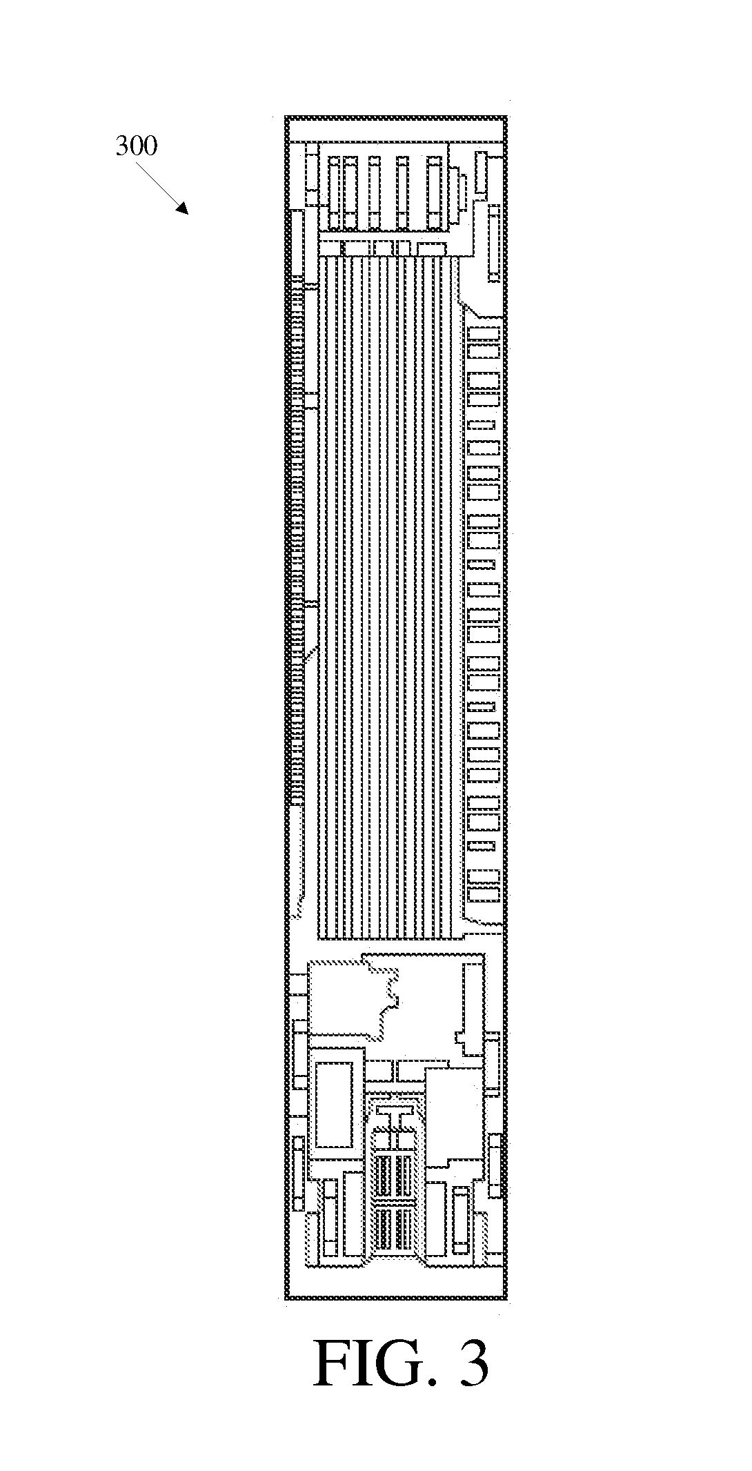
FIG. 3 is a top view of one exemplary embodiment of a pressure sensor;
FIG. 4 is a schematic view of one exemplary embodiment of an implantable valve having an RFID tag disposed therein;
FIG. 5 is a schematic view of the valve shown in FIG. 4 with an RFID tag disposed in an alternate location;
FIG. 6 is a schematic view of the valve shown in FIG. 4 with an RFID tag disposed in yet another location;
FIG. 7 is a schematic view of another embodiment of an implantable valve having an RFID tag disposed therein;
FIG. 8 is a cross-sectional view of the implantable valve of FIG. 4 implanted in a body and one exemplary embodiment of an external radio frequency telemetry reading device disposed adjacent thereto outside the body for reading a signal from the implantable valve; and
FIG. 9 is a perspective view of one exemplary embodiment of a radio frequency telemetry reading device.
DETAILED DESCRIPTION
Certain exemplary embodiments will now be described to provide an overall understanding of the principles of the structure, function, manufacture, and use of the devices and methods disclosed herein. One or more examples of these embodiments are illustrated in the accompanying drawings. Those skilled in the art will understand that the devices and methods specifically described herein and illustrated in the accompanying drawings are non-limiting exemplary embodiments and that the scope is defined solely by the claims. The features illustrated or described in connection with one exemplary embodiment may be combined with the features of other embodiments. Such modifications and variations are intended to be included within the scope of the present application.
Generally, methods and devices for storing and accessing data related to an implantable medical device, such as an implantable valve, are provided. The methods and devices are particularly useful in the context of valves for monitoring intra-ventricular pressure. In some embodiments, they can allow data related to a pressure sensor (or, for example, temperature or flow sensors) in an implantable valve to be stored on and retrievable from an implantable radio frequency identification (RFID) tag associated with a pressure sensor and/or an implantable valve, thereby providing convenient and reliable access to data related to the implantable valve. A person skilled in the art will appreciate that, while the methods and devices are described below in connection with an implantable valve for controlling cerebrospinal fluid and an associated pressure sensor, this description is by way of illustration only, and that the methods and devices can be used for a variety of medical procedures and in a variety of devices, including other kinds of sensors and/or sensors that are not disposed within valves.
FIGS. 1 and 2 illustrate one exemplary embodiment of an implantable valve 100 that includes a radio frequency identification (RFID) tag 114. The valve 100 can be used alone or in combination with a pressure sensor assembly 118 that has a pressure sensor 900 therein, and/or other pressure sensor assemblies disposed upstream or downstream of the valve 100. As shown the, RFID tag 114 can be disposed inside the valve 100, but in other embodiments, the RFID tag 114 can be disposed outside the valve or any distance apart from the valve and/or the sensor 900. In many embodiments, the RFID tag 114 can be offset from the pressure sensor to facilitate communication. As will be explained in more detail below, the RFID tag 114 can store and communicate data which, for example, can be related to, for example, the valve 100, the pressure sensor 900, and/or a patient.
While the implantable valve 100 can have virtually any configuration, and a variety of implantable valves known in the art can be used, as shown in FIG. 1 the implantable valve 100 has a valve housing 102 with proximal and distal ends 104a, 104b. The housing 102 can have virtually any configuration, shape, and size, preferably one making the housing 102 suitable for subcutaneous implantation. Fluid (e.g., CSF) can flow through the housing 102 from an inlet (fluid entry) port 106 at the proximal end 104a and out an outlet (fluid exit) port 110 at the distal end 104b. The location and size of the ports 106, 110 can vary, but in many embodiments they can be adapted to allow fluid to flow therethrough and into and out of the housing 102. The proximal and distal ends 104a, 104b of the valve 100 can each be open and adapted to couple to another medical device, such as a catheter. The valve housing 102 can contain a valve assembly 112 for controlling the flow of fluid from the inlet port 106 to the outlet port 110, and a pressure sensor assembly 118 for measuring a pressure of the fluid flowing through the valve 100, as will be described in more detail below with respect to FIG. 2. While the valve assembly 112 and the pressure sensor assembly 118 of the valve 100 are shown in-line with one another and with the inlet port 106 and outlet port 110, and the pressure sensor assembly 118 is positioned upstream of the valve 100, the valve 100 can have a variety of other configurations, and the valve assembly 112, the pressure sensor assembly 118, the inlet port 106, and the outlet port 110 can be positioned at various locations relative to one another. For example, the inlet port 106 can extend at a right angle with respect to the pressure sensor assembly 118 such that the inlet port 106 extends in a direction substantially transverse to a longitudinal axis of the valve 100. The valve assembly 112 can also have a variety of configurations. By way of non-limiting example, exemplary valves are described in U.S. Pat. Nos. 3,886,948, 4,332,255, 4,387,715, 4,551,128, 4,595,390, 4,615,691, 4,772,257, and 5,928,182, all of which are hereby incorporated by reference in their entireties.
As shown in FIG. 2, the pressure sensor assembly 118 can include the sensor 900, a sensor housing 902, a backing 904, and an RFID tag 114. The sensor housing 902 can have a variety of shapes and sizes, but in the illustrated exemplary embodiment the sensor housing 902 has a generally hemi-spherical or domed portion 910 that defines a reservoir therein. The sensor housing 902 can also include an inlet tube 912 that couples to the inlet port 106 of the valve 100, and an outlet tube 914 that couples to the outlet port 110 of the valve 100. When the sensor housing 902 is mated to the backing 904, the reservoir chamber defined by the housing 902 is sealed, thereby allowing fluid to flow from the inlet port 106 of the valve 100, through the sensor housing 902, through the valve 906, and out the outlet port 110 in the valve 100. The sensor housing 902 can also include a flange 916 formed around a base of the domed portion 910 to allow the device to be secured to tissue. For example, the flange 916 can include one or more suture holes formed therein for receiving suture to attach the flange 916 to tissue.
The pressure sensor 900, such as the exemplary pressure sensor 300 shown in FIG. 3, can be formed on a microchip which can be coupled to an antenna 117 for communicating a sensed pressure to an external device. The antenna 117 can have a substantially circular shape, and the microchip sensor can be coupled to the antenna 117 which can, for example, be in the form of a gold microcoil. The sensor 900 and the RFID tag 114 can also each include a fluid-impermeable coating, as further described below, to protect the sensor 900 and the RFID tag 114 from fluid flowing through the sensor housing 902 or from other fluid. The size of sensor can vary, but in one exemplary embodiment the microchip sensor 900 has a size that is in the range of about 1 mm to 3 mm, and more preferably that is about 2.5 mm.sup.2. Exemplary embodiments of a pressure sensor and antenna are described in more detail in U.S. Pat. No. 5,321,989, U.S. Pat. No. 5,431,057, EP Patent No. 1 312 302, and in co-pending, commonly assigned U.S. patent application Ser. No. 10/907,665, entitled "Pressure Sensing Valve" by Mauge et al., filed Apr. 11, 2005 (now published as U.S. Publication No. 2006-0211946 A1), all of which are hereby incorporated by reference.
In use, the sensor 900, which is disposed within the sensor housing 902, measures the pressure of fluid flowing through the sensor housing 902. In particular, the inlet port 106 of the valve 100 can be coupled to the ventricular catheter 120 for receiving fluid flow from one or more ventricles, and the outlet port 110 can be coupled to a drainage catheter 122. As fluid enters the sensor housing 902, the pressure of the fluid will apply a force to active sensor membranes formed on the sensor 900, thereby allowing the fluid pressure to be measured. The sensed pressure can be communicated, via the antenna, to an external reading device, as described further below. Performance of the sensor membranes can vary with factors such as temperature, its age, and its maintenance, and the membranes may need to be calibrated to correct for such variance. Calibration can vary from sensor to sensor. Calibration information, such as calibration coefficients and drift compensation values particular to the sensor 900, can be stored in the RFID tag 114 (as well as other kinds of information, which will be described in more detail below). Stored calibration information can be read by an external device, identified as associated with this particular sensor 900, and used to calibrate the sensor 900. An external reading device, e.g., a radio frequency ("RF") reader, can inductively couple to the RFID tag 114 and non-invasively communicate data for storage to the RFID tag 114 and/or non-invasively receive stored data from the RFID tag 114.
As shown, the sensor 900 and the RFID tag 114 can be disposed in the sensor housing 902, although the location of the RFID tag 114 can vary widely. For example, in other embodiments the RFID tag 114 can be remote from the sensor 900 and valve 100, for example, disposed outside the housing 902 or implanted in another area of the body. In many embodiments, the sensor 900 and the RFID tag 114 can be physically separate, without a physical link or connection (e.g., a mechanical, electrical, or communication link or connection) between them. Such an arrangement can allow for a flexible, independent design of, in this case, the sensor 900, valve 100, and RFID tag 114. For example, the valve 100 may be limited in size, and the RFID tag 114 can be located outside the valve 100 while the sensor 900 can be located within the valve 100. As another example, a sensor having a microchip (as described above in connection with FIG. 3) can dedicate the microchip to sensor functionality, and accordingly retain a relatively small size, while a separate RFID tag can provide storage related that sensor. In addition, in some embodiments the RFID tag can be "retrofitted" to previously implanted medical devices, for example, which were implanted without an RFID tag and do not have its storage and communication abilities. In some embodiments, even though the RFID tag and the pressure sensor, for example, are physically separate from one another (as in FIGS. 5-7, for example), their respective antennas can be located in proximity or adjacent to one another, so that both devices can be read with an external reading device in one location. The external reading device may communicate with each device using a different frequency, protocol, etc., as will be described in more detail below.
As shown in FIG. 2, the valve 100 (or other device in which the RFID tag 114 is embedded, or associated with) can have features to protect the RFID tag 114. For example, as shown in FIG. 2 the sensor assembly 118 of the valve 100 can include a washer 908, which can be provided to seat the sensor 900 and/or the RFID tag 114, such that the washer 908 and the sensor 900 and/or the RFID tag 114 are positioned against the backing 904. The washer 908 can also be configured such that the sensor 900 and/or the RFID tag 114 are sub-flush with the washer 908, for example, to protect the sensor 900 and the RFID tag 114 from potential damage when the domed portion 910 of the housing 902 is depressed. The sensor assembly 118 can also include a needle guard 906 for protecting the sensor 900 and the RFID tag 114. In particular, the needle guard 906 can protect the sensor 900 and the RFID tag 114 from coming into contact with the domed portion 910 of the housing 902 when the domed portion 910 is depressed, as the needle guard 906 can be positioned between the sensor 900 and the domed portion 910. The needle guard 906 can also be provided to protect the sensor 900 and the RFID tag 114 from a needle being inserted through the domed portion 910 of the sensor housing 902. While the shape of the needle guard 906 can vary, in an exemplary embodiment, as shown, the needle guard 906 has a substantially planar, circular shape and it is adapted to be disposed between the domed portion 910 of the housing 902 and the sensor 900. The needle guard 906 can, however, include an opening formed therein and positioned adjacent to the microchip sensor 900 to allow fluid flowing through the sensor housing 902 to come into contact with the sensor 900. In an exemplary embodiment, a flange or protective member 918 is disposed over the opening, without blocking the opening from fluid flow, to prevent a user from accidentally inserted a needle through the opening. Further information on these features can be found in U.S. Publication No. 2006-0211946 A1, referenced above.
FIG. 4 is a schematic illustration of one embodiment of the implantable valve 100 of FIGS. 1 and 2 showing one possible location of the RFID tag 114 disposed within the housing 102. In this embodiment, the housing 102 has a substantially linear configuration with a reservoir 108 having a larger area than ports 106, 110, which can be advantageous for checking the shunt's patency, tapping the CSF, to administer therapy, or to house pressure or flow sensors. As indicated by directional arrows, fluid (e.g., CSF) can flow through the inlet port 106, through the reservoir 108, and out the outlet port 110. As shown, the RFID tag 114, for storing data and for communicating stored data, is disposed in the sensor housing 902 that defines the reservoir 108.
As mentioned above, the RFID tag 114 can be disposed in a wide variety of locations. For example, it can be disposed in the valve 100, disposed at a location proximate to the valve 100, or implanted at any other location within the patient associated with the valve 100, including at a location remote from the valve 100. FIG. 5 shows another schematic embodiment of the valve 100 in which the RFID tag 114 is disposed proximate to the distal end 104b of the valve 100. FIG. 6 shows an alternate schematic embodiment of the valve 100 in which the RFID tag 114 is disposed outside the valve 100, in this example embodiment proximate to the proximal end 104a of the valve 100, although the RFID tag 114 can be implanted any distance from the valve 100. FIG. 7 illustrates yet another schematic embodiment of the valve 100 where the RFID tag 114 is disposed in an offset tag housing area 400 of the reservoir 108. It should be understood that the reservoir 108 can have any size and shape, including a shape accommodating the RFID tag 114. In the embodiments shown in FIGS. 4-6, the reservoir 108 has a substantially rectangular shape, while in the embodiment shown in FIG. 7, the reservoir has a substantially circular shape at its proximal end and a substantially rectangular shape at its distal end. In other embodiments, the RFID tag 114 can be non-implantable and can be embedded or housed in a RFID bracelet, key fob, card, etc., to hold information, and issued or given to a patient.
The housing 102 can be formed from a variety of materials. In an exemplary embodiment, however, the housing 102 is formed from a flexible, biocompatible material. Suitable materials include, for example, polymers such as silicones, polyethylene, and polyurethanes, all of which are known in the art. The housing 102 can also optionally be formed from a radio-opaque material. A person skilled in the art will appreciate that the materials are not limited to those listed herein and that a variety of other biocompatible materials having the appropriate physical properties to enable the desired performance characteristics can be used.
The valve 100 and/or the RFID tag 114 can also optionally include a coating 116 that is adapted to hermetically seal all or at least a portion of the valve 100, the RFID tag 114, and/or other components such as a sensor, an antenna, a connector, etc. The coating 116 can be applied to only a portion of the RFID tag 114 that could be exposed to fluid, or it can be applied to the RFID tag 114, and optionally the valve 100. The RFID tag 114 and the valve 100 can be coated separately with different coatings or together in a single coating. In the embodiment shown in FIG. 4 in which the RFID tag 114 is disposed in the valve 100, the RFID tag 114 is preferably pre-coated prior to coupling the sensor assembly to the housing 102. Once coated, the RFID tag 114 can be appropriately positioned. An adhesive or other mating technique can be used to affix the RFID tag 114 within the housing 102, such as in the embodiment shown in FIG. 5, however, in some embodiments it can be useful to allow the RFID tag 114 to be removed from the valve 100 if necessary.
Alternatively, the valve 100 can be coated after the RFID tag 114 is disposed in the valve 100 or located elsewhere to form a protective sheath over the RFID tag 114 and the housing 102. The ports 106, 110 can be protected from any coating applied thereto, formed after the coating is applied, or be cleared of any coating applied thereto to allow fluid to flow therethrough. In other embodiments, only certain components of the valve 100 can be coated. A person skilled in the art will appreciate that a variety of other techniques can be used to seal the RFID tag 114 and/or other components of the valve 100.
The material used to form the coating 116 can vary, and a variety of techniques can be used to apply the coating. By way of non-limiting example, suitable materials include polyurethane, silicone, solvent-based polymer solutions, and any other polymer that will adhere to the components to which it is applied to, and suitable techniques for applying the coating include spray-coating or dip-coating.
Referring to FIGS. 4-8, the shape, technical specifications, and size of the RFID tag can vary widely (as can the RFID tag 114 of FIGS. 1 and 2). In many embodiments, a relatively small RFID tag can be used so as to minimize the footprint of the tag in the device, for example with dimensions in a range of about 5 mm to 10 mm, but in other embodiments, tags with dimensions of about 3 mm to 50 mm can be used and any size is possible. The RFID tag 114 can be adapted to be in communication with an external device (e.g., by having an antenna) and to store data.
The RFID tag 114 can have any shape, such as elliptical, circular, or rectangular (including square), and can have virtually any size. The RFID tag 114 can be an off-the-shelf component. The following table (Table 1) lists, by way of example only, available RFID tags suitable for use with the devices and methods described herein. Passive as well as semi-passive and active tags can be used, although semi-passive and active tags sometimes are larger than passive tags because they can incorporate an internal battery, e.g., for power purposes.
TABLE-US-00001 TABLE 1 Frequency Tag Type 125 KHz 5-7 MHz 13.56 MHz 303/433 MHz 860-960 MHz 2.45 GHz Passive ISO11784/5, ISO10536 (ISO15693) -- ISO18000-6 ISO18000-4 14223 iPico (ISO15693) Electronic Intellitag ISO18000-2 DF/iPX MIFARE Product Code .mu.-chip (ISO14443) ("EPC") Class 0 Tag-IT EPC Class 1 (ISO15693) EPC GEN II ISO18000-3 Intellitag tolls (Title 21) rail (Association of American Railroads ("AAR") S918) Semi- -- -- -- -- rail (AAR S918) ISO18000-4 Passive Title 21 Alien BAP Active -- -- -- Savi (American -- ISO18000-4 National WhereNet Standards Institute (ANSI 371.1) ("ANSI") 371.2) ISO18000-7 RFCode
The RFID tag 114 can store and/or communicate various types of data. The types of data stored can be selected by a user. As indicated above, the data can be related to a valve or any other implanted device(s), a patient associated with the valve, the RFID tag, sensed or measured values (including historical values), and/or characteristics of fluid flowing through the valve or valve assembly. Non-limiting examples of data related to the valve 100 (or other devices) can include date of device manufacture, device type (e.g., fixed or programmable), device identifier code, and device maintenance history. Non-limiting examples of data related to a patient can include patient identification (e.g., name, identifying code such as Social Security Number, age, etc.), medical history information (e.g., dates of pervious doctor examination(s), disease history, etc.), and date of valve implantation. Non-limiting examples of data related to the RFID tag 114 can include available memory space, date of tag manufacture, date of tag implantation, tag type, tag identifier code, and tag maintenance history. Non-limiting examples of data related to implanted sensors or sensed characteristics can include current pressure setting (e.g., a rate of fluid flow through the valve assembly 112), previous pressure setting(s), date(s) of programming/adjustments (if the valve 100 is programmable), calibration parameter(s), settings of previous calibration parameter(s), dates of previous calibration parameter(s), reasons for modifying previous calibration parameter(s) (e.g., adverse medical reactions such as fever or headache), and drift compensation values. Also, information related to a pressure sensor, such as date of implantation, sensor type, sensor ID, values read, zeroing of the sensor, date of zeroing, specific pressure reading and date taken, can be stored. Storing and communicating characteristic data such as calibration parameters and drift compensation values can include polynomial coefficients to calculate an actual pressure value from a measured pressure value. The RFID tag 114 can store such data and allow an external RF reader to obtain a correct measurement from the valve 100 without having to depend on external storage devices.
As illustrated in FIG. 8, the RFID tag 114 can be adapted to interact with a wireless signal 500 from an external reading device, such as an RF telemetry device 502 (shown in more detail in FIG. 9). The reading device 502 can emit a signal 500 at one frequency or over a range of frequencies and can receive a response thereto, e.g., from the RFID tag 114 or a sensor.
Virtually any type of external reading device can be used as the RF telemetry device 502. In one exemplary embodiment, the RF telemetry device 502 can include an RF module (e.g., transmitter and receiver), a control unit (e.g., microcontroller), a coupling element to the transponder (e.g., antenna), and an additional interface (e.g., Recommended Standard (RS) 232, RS-485, Firewire, USB, Bluetooth, ZigBee, etc.) to enable communication with another external device (e.g., a personal computer). The RF telemetry device 502 can provide the power required by the RFID tag 114 to operate, e.g., through the coupling element. The RF telemetry device 502, as shown in FIG. 8, can be positioned adjacent to the RFID tag 114 to telemetrically communicate with the RFID tag 114, and thereby obtain and/or transmit data. Further information on the use of such RFID tags, including techniques for interrogating them and examples of them, can be obtained from U.S. Pat. Nos. 6,025,725, and 6,278,379, and U.S. Patent Application Publication No. 20040134991, all of which are hereby by incorporated by reference in their entireties.
In some embodiments, multiple RFID tags and/or other devices (such as the pressure sensor described above) capable of wireless communication can be implanted in a patient. Multiple RF telemetry devices can be used to communicate with these devices. Alternatively, the RF telemetry device can provide the ability to communicate with multiple devices, using different frequencies, different communication protocols, and so on. For example, the same RF telemetry device 502 can obtain data from both the pressure sensor and the RFID tag, which as mentioned previously can have antennas located in proximity to one another to facilitate such communication. In some embodiments, the RF telemetry device 502 can read identification data, such as serial numbers, from the sensor and/or the RFID tag to identify from which device it is receiving data.
In other embodiments, the RFID tag 114 can store data related to not one but a plurality of implanted medical devices, which may be devices that were implanted concurrently with the RFID tag 114 or those being "retrofitted" or "upgraded" with later implantation of an RFID tag. The RF telemetry device 502 can read from the RFID tag identification data (and other data) for each of a plurality of implanted devices. The RFID tag can store and output data so as to associate it with the implanted device to which it relates, for example via a table correlating device identifiers with data values.
In another aspect, a method for obtaining data related to medical device, such as the valve and/or pressure sensor of FIGS. 1-2, is provided. The inlet port 106 of the valve 100 can be coupled to a proximal end of a ventricular catheter 120 that has had its distal end positioned in a patient's ventricle. As shown in FIG. 8, the valve 100 can be implanted in a patient, such as a patient's shoulder area, while the typically more flexible catheter can extend through the patient to the ventricle. A drainage catheter 122 can be coupled to the outlet port 110 of the valve 100, in which the drainage catheter can extend through the patient to an area where excess fluid can safely drain. The rate of fluid flowing through the valve 100 from the inlet port 106 to the outlet port 110 can be controlled by the valve assembly 112. Data related to the valve 100 can be obtained at an external reading device (e.g., using the RF telemetry device 502) from an antenna coupled to the RFID tag 114 that is associated with the valve 100.
In the embodiment shown in FIG. 8, the RFID tag 114 is disposed in a valve 100 implanted in a shoulder area of a patient (shown for simplicity without catheters in communication with either of the ports 106, 110). However, it should be understood that the valve can be implanted virtually anywhere, for example subcutaneously behind the ear, or on the head, torso, etc. Further, as indicated above, the RFID tag 114 can be disposed outside the valve 100, at a location proximate or remote to the valve 100. The method can include implanting the RFID tag 114 concurrently or subsequently (e.g., as a replacement or retrofit) with the valve or other medical device.
In some embodiments, multiple pressure sensor assemblies can be used, each with an associated RFID tag, and the pressure sensor assemblies can be disposed at various locations relative to one another, not necessarily in a valve. The use of multiple pressure sensor assemblies can be particularly advantageous as it can allow a differential pressure of the system to be obtained. The differential pressure of the system should be equal to the operating pressure of the system, thus indicating whether the system is performing properly. CSF can flow from a patient's ventricle through a catheter (or other medical device) to the inlet port 106 and through the valve 100. Thus, the pressure of fluid flowing through the reservoir 108 of the valve 100 can correlate to the patient's ICP despite the valve's implantation at a location other than the patient's ventricle. Moreover, as indicated above, the RFID tag 114 can be disposed outside the valve 100, at a location proximate or remote to the valve 100.
Further information on wireless shunts can be obtained from U.S. patent application Ser. No. 11/931,041, entitled "Wireless Pressure Setting Indicator" by Salim Kassem, U.S. patent application Ser. No. 11/931,127, entitled "Wireless Flow Sensor" by Salim Kassem, and U.S. patent application Ser. No. 11/931,151, entitled "Wireless Pressure Sensing Shunts" by Salim Kassem, all of which are being filed on the same date as the present application and which are hereby incorporated by reference in their entirety. Also incorporated by reference in its entirety is co-pending, commonly assigned U.S. patent application Ser. No. 10/907,665, entitled "Pressure Sensing Valve" and published as U.S. Publication No. 2006-0211946 A1.
A person skilled in the art will appreciate that the various methods and devices disclosed herein can be formed from a variety of materials. Moreover, particular components can be implantable and in such embodiments the components can be formed from various biocompatible materials known in the art. Exemplary biocompatible materials include, by way of non-limiting example, composite plastic materials, biocompatible metals and alloys such as stainless steel, titanium, titanium alloys and cobalt-chromium alloys, glass, and any other material that is biologically compatible and non-toxic to the human body.
One skilled in the art will appreciate further features and advantages of the invention based on the above-described embodiments. Accordingly, the invention is not to be limited by what has been particularly shown and described, except as indicated by the appended claims. All publications and references cited herein are expressly incorporated herein by reference in their entirety.
* * * * *
D00000
D00001
D00002
D00003
D00004
D00005
D00006
XML
uspto.report is an independent third-party trademark research tool that is not affiliated, endorsed, or sponsored by the United States Patent and Trademark Office (USPTO) or any other governmental organization. The information provided by uspto.report is based on publicly available data at the time of writing and is intended for informational purposes only.
While we strive to provide accurate and up-to-date information, we do not guarantee the accuracy, completeness, reliability, or suitability of the information displayed on this site. The use of this site is at your own risk. Any reliance you place on such information is therefore strictly at your own risk.
All official trademark data, including owner information, should be verified by visiting the official USPTO website at www.uspto.gov. This site is not intended to replace professional legal advice and should not be used as a substitute for consulting with a legal professional who is knowledgeable about trademark law.