Systems for accessing nerves within bone
Pellegrino , et al.
U.S. patent number 10,265,099 [Application Number 15/040,268] was granted by the patent office on 2019-04-23 for systems for accessing nerves within bone. This patent grant is currently assigned to Relievant Medsystems, Inc.. The grantee listed for this patent is Relievant Medsystems, Inc.. Invention is credited to Harold Carrison, Samit Patel, Richard Pellegrino.


| United States Patent | 10,265,099 |
| Pellegrino , et al. | April 23, 2019 |
Systems for accessing nerves within bone
Abstract
System and methods are shown having a tube-within-tube assembly with a deployable curved deflectable tube or cannula that deploys from a straight cannula or trocar. The curved cannula has pre-curved distal end to create an angular range of 0.degree. to 180.degree. when fully deployed from the straight trocar. The curve is configured such that the flexible element carrying a treatment device can navigate through the angular range of deployment of the curved cannula. The curved cannula allows the flexible element to navigate through a curve within bone without veering off towards an unintended direction.
| Inventors: | Pellegrino; Richard (Ashburn, VA), Patel; Samit (San Francisco, CA), Carrison; Harold (Pleasanton, CA) | ||||||||||
|---|---|---|---|---|---|---|---|---|---|---|---|
| Applicant: |
|
||||||||||
| Assignee: | Relievant Medsystems, Inc.
(Minneapolis, MN) |
||||||||||
| Family ID: | 42060393 | ||||||||||
| Appl. No.: | 15/040,268 | ||||||||||
| Filed: | February 10, 2016 |
Prior Publication Data
| Document Identifier | Publication Date | |
|---|---|---|
| US 20160324541 A1 | Nov 10, 2016 | |
Related U.S. Patent Documents
| Application Number | Filing Date | Patent Number | Issue Date | ||
|---|---|---|---|---|---|
| 13862242 | Apr 12, 2013 | 9259241 | |||
| 12566895 | Apr 16, 2013 | 8419730 | |||
| 61100553 | Sep 26, 2008 | ||||
| Current U.S. Class: | 1/1 |
| Current CPC Class: | A61B 18/149 (20130101); A61B 18/18 (20130101); A61B 18/20 (20130101); A61B 17/1642 (20130101); A61B 18/14 (20130101); A61B 17/3472 (20130101); A61B 17/16 (20130101); A61B 17/34 (20130101); A61B 17/3403 (20130101); A61B 18/148 (20130101); A61B 18/1815 (20130101); A61B 17/8819 (20130101); A61B 18/1487 (20130101); A61N 7/00 (20130101); A61B 17/3421 (20130101); A61B 17/1671 (20130101); A61B 2018/00577 (20130101); A61B 2018/00011 (20130101); A61B 2018/00434 (20130101); A61B 18/0206 (20130101); A61N 2007/0026 (20130101); A61N 2007/025 (20130101); A61B 18/1492 (20130101); A61B 2018/00017 (20130101); A61B 2018/00339 (20130101) |
| Current International Class: | A61B 18/12 (20060101); A61B 18/14 (20060101); A61B 18/20 (20060101); A61B 18/18 (20060101); A61B 17/88 (20060101); A61B 17/34 (20060101); A61B 17/56 (20060101); A61N 7/00 (20060101); A61B 17/16 (20060101); A61B 18/00 (20060101); A61B 18/02 (20060101); A61N 7/02 (20060101) |
References Cited [Referenced By]
U.S. Patent Documents
| 3565062 | February 1971 | Kuris |
| 3822708 | July 1974 | Zilber |
| 3845771 | November 1974 | Vise |
| 3920021 | November 1975 | Hiltebrandt |
| 3938502 | February 1976 | Born |
| 3997408 | December 1976 | Barba et al. |
| 4044774 | August 1977 | Corgin et al. |
| 4116198 | September 1978 | Roos |
| 4311154 | January 1982 | Sterzer et al. |
| 4312364 | January 1982 | Convert et al. |
| 4378806 | April 1983 | Henley-Cohn |
| 4448198 | May 1984 | Turner |
| 4449528 | May 1984 | Auth et al. |
| 4462408 | July 1984 | Silverstein et al. |
| 4528979 | July 1985 | Marchenko et al. |
| 4530360 | July 1985 | Duarte |
| 4569351 | February 1986 | Tang |
| 4573448 | March 1986 | Kambin |
| 4586512 | May 1986 | Do-huu |
| 4601296 | July 1986 | Yerushalmi |
| 4612940 | September 1986 | Kasevich et al. |
| 4657017 | April 1987 | Sorochenko |
| 4662383 | May 1987 | Sogawa et al. |
| 4671293 | June 1987 | Shaulov |
| 4676258 | June 1987 | Inokuchi et al. |
| 4679561 | July 1987 | Doss |
| 4681122 | July 1987 | Winters et al. |
| 4750499 | June 1988 | Hoffer |
| 4754757 | July 1988 | Feucht |
| 4757820 | July 1988 | Itoh |
| 4774967 | October 1988 | Zanakis et al. |
| 4800899 | January 1989 | Elliott |
| 4813429 | March 1989 | Eshel et al. |
| 4841977 | June 1989 | Griffith et al. |
| 4907589 | March 1990 | Cosman |
| 4924863 | May 1990 | Sterzer |
| 4936281 | June 1990 | Stasz |
| 4950267 | August 1990 | Ishihara et al. |
| 4951677 | August 1990 | Crowley et al. |
| 4955377 | September 1990 | Lennox et al. |
| 4959063 | September 1990 | Kojima |
| 4961435 | October 1990 | Kitagawa et al. |
| 4963142 | October 1990 | Loertscher |
| 4966144 | October 1990 | Rochkind et al. |
| 4967765 | November 1990 | Turner et al. |
| 4976711 | December 1990 | Parins et al. |
| 4977902 | December 1990 | Sekino et al. |
| 5000185 | March 1991 | Yock |
| 5002058 | March 1991 | Martinelli |
| 5002059 | March 1991 | Crowley et al. |
| 5007437 | April 1991 | Sterzer |
| 5025778 | June 1991 | Silverstein et al. |
| 5031618 | July 1991 | Mullett |
| 5061266 | October 1991 | Hakky |
| 5070879 | December 1991 | Herres |
| RE33791 | January 1992 | Carr |
| 5078736 | January 1992 | Behl |
| 5080660 | January 1992 | Buelna |
| 5084043 | January 1992 | Hertzmann et al. |
| 5090414 | February 1992 | Takano |
| 5098431 | March 1992 | Rydell |
| 5106376 | April 1992 | Mononen et al. |
| 5108404 | April 1992 | Scholten et al. |
| 5131397 | July 1992 | Crowley |
| 5147355 | September 1992 | Friedman et al. |
| 5156157 | October 1992 | Valenta, Jr. et al. |
| 5158536 | October 1992 | Sekins et al. |
| 5161533 | November 1992 | Prass et al. |
| 5167231 | December 1992 | Matsui |
| 5186177 | February 1993 | O'Donnell et al. |
| 5190540 | March 1993 | Lee |
| 5190546 | March 1993 | Jervis |
| 5201729 | April 1993 | Hertzmann et al. |
| 5207672 | May 1993 | Martinelli et al. |
| 5209748 | May 1993 | Daikuzono |
| 5222953 | June 1993 | Dowlatshahi |
| 5226430 | July 1993 | Spear et al. |
| 5242439 | September 1993 | Larsen et al. |
| 5255679 | October 1993 | Imran |
| 5271408 | December 1993 | Breyer et al. |
| 5273026 | December 1993 | Wilk |
| 5281213 | January 1994 | Milder et al. |
| 5281215 | January 1994 | Milder et al. |
| 5282468 | February 1994 | Klepinski |
| 5292321 | March 1994 | Lee |
| 5295484 | March 1994 | Marcus et al. |
| 5300085 | April 1994 | Yock |
| 5304214 | April 1994 | DeFord et al. |
| 5305756 | April 1994 | Entrekin et al. |
| 5314463 | May 1994 | Camps et al. |
| 5320617 | June 1994 | Leach |
| 5324255 | June 1994 | Pasafaro et al. |
| 5325860 | July 1994 | Seward et al. |
| 5342292 | August 1994 | Nita et al. |
| 5342357 | August 1994 | Nardella |
| 5342409 | August 1994 | Mullett |
| 5344435 | September 1994 | Turner et al. |
| 5345940 | September 1994 | Seward et al. |
| 5348554 | September 1994 | Imran et al. |
| 5350377 | September 1994 | Winston et al. |
| 5351691 | October 1994 | Brommersma |
| 5366443 | November 1994 | Eggers et al. |
| 5366490 | November 1994 | Edwards et al. |
| 5368031 | November 1994 | Cline et al. |
| 5368035 | November 1994 | Hamm et al. |
| 5368557 | November 1994 | Nita et al. |
| 5368558 | November 1994 | Nita |
| 5370675 | December 1994 | Edwards et al. |
| 5370678 | December 1994 | Edwards et al. |
| 5372138 | December 1994 | Crowley et al. |
| 5374265 | December 1994 | Sand |
| 5383876 | January 1995 | Nardella |
| 5385148 | January 1995 | Lesh et al. |
| 5385544 | January 1995 | Edwards et al. |
| 5391197 | February 1995 | Burdette et al. |
| 5391199 | February 1995 | Ben-Haim |
| 5405376 | April 1995 | Mulier et al. |
| 5411527 | May 1995 | Alt |
| 5417719 | May 1995 | Hull et al. |
| 5419767 | May 1995 | Eggers et al. |
| 5421338 | June 1995 | Crowley et al. |
| 5423811 | June 1995 | Imran et al. |
| 5431649 | July 1995 | Mulier et al. |
| 5433739 | July 1995 | Sluijter et al. |
| D361555 | August 1995 | Bettin et al. |
| 5437661 | August 1995 | Rieser |
| 5441499 | August 1995 | Fritzsch |
| 5443463 | August 1995 | Stern et al. |
| 5447509 | September 1995 | Millis et al. |
| 5449380 | September 1995 | Chin |
| 5454373 | October 1995 | Koger et al. |
| 5458596 | October 1995 | Lax et al. |
| 5458597 | October 1995 | Edwards et al. |
| 5471988 | December 1995 | Fujio et al. |
| 5472441 | December 1995 | Edwards et al. |
| 5474530 | December 1995 | Passafaro et al. |
| 5484432 | January 1996 | Sand |
| 5486170 | January 1996 | Winston et al. |
| 5501703 | March 1996 | Holscheimer et al. |
| 5505730 | April 1996 | Edwards |
| 5514130 | May 1996 | Baker |
| 5524624 | June 1996 | Tepper et al. |
| 5526815 | June 1996 | Granz et al. |
| 5529580 | June 1996 | Hagino et al. |
| 5540679 | July 1996 | Fram et al. |
| 5540681 | July 1996 | Strul et al. |
| 5540684 | July 1996 | Hassler, Jr. |
| 5545161 | August 1996 | Imran |
| 5560362 | October 1996 | Sliwa, Jr. et al. |
| 5565005 | October 1996 | Erickson et al. |
| 5569242 | October 1996 | Lax et al. |
| 5571088 | November 1996 | Lennox et al. |
| 5571147 | November 1996 | Sluijter et al. |
| 5575772 | November 1996 | Lennox |
| 5575788 | November 1996 | Baker et al. |
| 5588432 | December 1996 | Crowley |
| 5596988 | January 1997 | Markle et al. |
| 5601526 | February 1997 | Chapelon et al. |
| 5606974 | March 1997 | Castellano et al. |
| 5609151 | March 1997 | Mulier et al. |
| 5620479 | April 1997 | Diederich |
| 5628317 | May 1997 | Starkebaum et al. |
| 5630426 | May 1997 | Shmulewitz et al. |
| 5630837 | May 1997 | Crowley |
| 5643319 | July 1997 | Green et al. |
| 5643330 | July 1997 | Holsheimer et al. |
| 5647361 | July 1997 | Damadian |
| 5647871 | July 1997 | Levine et al. |
| 5658278 | August 1997 | Imran et al. |
| 5672173 | September 1997 | Gough et al. |
| 5681282 | October 1997 | Eggers et al. |
| 5683366 | November 1997 | Eggers et al. |
| 5685839 | November 1997 | Baker et al. |
| 5687729 | November 1997 | Schaetzle |
| 5693052 | December 1997 | Weaver |
| 5697281 | December 1997 | Eggers et al. |
| 5697536 | December 1997 | Eggers et al. |
| 5697882 | December 1997 | Eggers et al. |
| 5697909 | December 1997 | Eggers et al. |
| 5697927 | December 1997 | Imran et al. |
| 5700262 | December 1997 | Acosta et al. |
| 5718231 | February 1998 | Chen et al. |
| 5720286 | February 1998 | Chapelon et al. |
| 5720287 | February 1998 | Chapelon et al. |
| 5722403 | March 1998 | McGee et al. |
| 5725494 | March 1998 | Brisken |
| 5728062 | March 1998 | Brisken |
| 5730706 | March 1998 | Garnies |
| 5733315 | March 1998 | Burdette et al. |
| 5735280 | April 1998 | Sherman et al. |
| 5735811 | April 1998 | Brisken |
| 5735846 | April 1998 | Fleischman et al. |
| 5735847 | April 1998 | Gough et al. |
| 5738680 | April 1998 | Mueller et al. |
| 5741249 | April 1998 | Moss et al. |
| 5743904 | April 1998 | Edwards |
| 5746737 | May 1998 | Saadat |
| 5752969 | May 1998 | Cunci et al. |
| 5755663 | May 1998 | Johnson et al. |
| 5762066 | June 1998 | Law et al. |
| 5762616 | June 1998 | Talish |
| 5766153 | June 1998 | Eggers et al. |
| 5766231 | June 1998 | Erickson et al. |
| 5776092 | July 1998 | Farin et al. |
| 5785705 | July 1998 | Baker |
| 5800378 | September 1998 | Edwards et al. |
| 5800429 | September 1998 | Edwards |
| 5800432 | September 1998 | Swanson |
| 5807237 | September 1998 | Tindel |
| 5807391 | September 1998 | Wijkamp |
| 5807392 | September 1998 | Eggers |
| 5807395 | September 1998 | Mulier et al. |
| 5810764 | September 1998 | Eggers et al. |
| 5817021 | October 1998 | Reichenberger |
| 5824021 | October 1998 | Rise |
| 5840031 | November 1998 | Crowley |
| 5843019 | December 1998 | Eggers et al. |
| 5843021 | December 1998 | Edwards et al. |
| 5844092 | December 1998 | Presta et al. |
| 5846218 | December 1998 | Brisken et al. |
| 5849011 | December 1998 | Jones et al. |
| 5855576 | January 1999 | LeVeen et al. |
| 5860951 | January 1999 | Eggers et al. |
| 5865788 | February 1999 | Edwards et al. |
| 5865801 | February 1999 | Houser |
| 5868740 | February 1999 | LeVeen et al. |
| 5871469 | February 1999 | Eggers et al. |
| 5871470 | February 1999 | McWha |
| 5871481 | February 1999 | Kannenberg et al. |
| 5873855 | February 1999 | Eggers et al. |
| 5873877 | February 1999 | McGaffigan et al. |
| 5876398 | March 1999 | Mulier et al. |
| 5888198 | March 1999 | Eggers et al. |
| 5891095 | April 1999 | Eggers et al. |
| 5895370 | April 1999 | Edwards et al. |
| 5902272 | May 1999 | Eggers et al. |
| 5902308 | May 1999 | Murphy |
| 5904681 | May 1999 | West, Jr. |
| 5906613 | May 1999 | Mulier et al. |
| 5916213 | June 1999 | Haissaguerre et al. |
| 5916214 | June 1999 | Cosio |
| 5919188 | July 1999 | Shearon et al. |
| 5931805 | August 1999 | Brisken |
| 5935123 | August 1999 | Edwards et al. |
| 5938582 | August 1999 | Ciamacco et al. |
| 5941722 | August 1999 | Chen |
| 5941876 | August 1999 | Nardella et al. |
| 5944715 | August 1999 | Goble et al. |
| 5948007 | September 1999 | Starkebaum et al. |
| 5948008 | September 1999 | Daikuzono |
| 5954716 | September 1999 | Sharkey et al. |
| 5964727 | October 1999 | Edwards et al. |
| 5967988 | October 1999 | Briscoe et al. |
| 5976105 | November 1999 | Marcove et al. |
| 5983141 | November 1999 | Sluijter et al. |
| 5997497 | December 1999 | Nita et al. |
| 6001095 | December 1999 | de la Rama et al. |
| 6007533 | December 1999 | Casscells et al. |
| 6007570 | December 1999 | Sharkey et al. |
| 6012457 | January 2000 | Lesh |
| 6014588 | January 2000 | Fitz |
| 6016452 | January 2000 | Kasevich |
| 6016809 | January 2000 | Mulier et al. |
| 6017356 | January 2000 | Frederick et al. |
| 6019776 | February 2000 | Preissman et al. |
| 6022334 | February 2000 | Edwards et al. |
| 6024733 | February 2000 | Eggers et al. |
| 6024740 | February 2000 | Lesh et al. |
| 6030374 | February 2000 | McDaniel |
| 6030402 | February 2000 | Thompson et al. |
| 6032673 | March 2000 | Langberg et al. |
| 6032674 | March 2000 | Eggers et al. |
| 6033411 | March 2000 | Preissman |
| 6035238 | March 2000 | Ingle et al. |
| 6038480 | March 2000 | Hrdlicka et al. |
| 6045532 | April 2000 | Eggers et al. |
| 6046187 | April 2000 | Berde et al. |
| 6047214 | April 2000 | Mueller et al. |
| 6050995 | April 2000 | Durgin |
| 6053172 | April 2000 | Hovda et al. |
| 6053909 | April 2000 | Shadduck |
| 6063078 | May 2000 | Wittkampf |
| 6063079 | May 2000 | Hovda et al. |
| 6066134 | May 2000 | Eggers et al. |
| 6068642 | May 2000 | Johnson et al. |
| 6071279 | June 2000 | Whayne et al. |
| 6073051 | June 2000 | Sharkey et al. |
| 6074352 | June 2000 | Hynynen et al. |
| 6086585 | July 2000 | Hovda et al. |
| 6090105 | July 2000 | Zepeda et al. |
| 6095149 | August 2000 | Sharkey et al. |
| 6099499 | August 2000 | Ciamacco |
| 6099514 | August 2000 | Sharkey et al. |
| 6102046 | August 2000 | Weinstein et al. |
| 6104957 | August 2000 | Alo et al. |
| 6105581 | August 2000 | Eggers et al. |
| 6106454 | August 2000 | Berg et al. |
| 6109268 | August 2000 | Thapliyal et al. |
| 6112122 | August 2000 | Schwardt et al. |
| 6113597 | September 2000 | Eggers et al. |
| 6117101 | September 2000 | Diederich et al. |
| 6117109 | September 2000 | Eggers et al. |
| 6117128 | September 2000 | Gregory |
| 6120467 | September 2000 | Schallhorn |
| 6120502 | September 2000 | Michelson |
| 6122549 | September 2000 | Sharkey et al. |
| 6126682 | October 2000 | Ashley et al. |
| 6137209 | October 2000 | Dahlberg et al. |
| 6139545 | October 2000 | Utley et al. |
| 6142992 | November 2000 | Cheng et al. |
| 6143019 | November 2000 | Motamedi et al. |
| 6146380 | November 2000 | Racz et al. |
| 6149620 | November 2000 | Baker et al. |
| 6159194 | December 2000 | Eggers et al. |
| 6159208 | December 2000 | Hovda et al. |
| 6161048 | December 2000 | Sluijter et al. |
| 6164283 | December 2000 | Lesh |
| 6165172 | December 2000 | Farley et al. |
| 6168593 | January 2001 | Sharkey et al. |
| 6169924 | January 2001 | Meloy et al. |
| 6171239 | January 2001 | Humphrey |
| 6176857 | January 2001 | Ashley |
| 6179824 | January 2001 | Eggers et al. |
| 6179836 | January 2001 | Eggers et al. |
| 6179858 | January 2001 | Squire et al. |
| 6183469 | February 2001 | Thapliyal et al. |
| 6190381 | February 2001 | Olsen et al. |
| 6190383 | February 2001 | Schmaltz et al. |
| 6193715 | February 2001 | Wrublewski et al. |
| 6203542 | March 2001 | Ellsberry et al. |
| 6206842 | March 2001 | Tu et al. |
| 6210393 | April 2001 | Brisken |
| 6210402 | April 2001 | Olsen et al. |
| 6210415 | April 2001 | Bester |
| 6216704 | April 2001 | Ingle et al. |
| 6221038 | April 2001 | Brisken |
| 6224592 | May 2001 | Eggers et al. |
| 6228046 | May 2001 | Brisken |
| 6228078 | May 2001 | Eggers et al. |
| 6228082 | May 2001 | Baker et al. |
| 6231516 | May 2001 | Keilman et al. |
| 6231528 | May 2001 | Kaufman et al. |
| 6231571 | May 2001 | Ellman et al. |
| 6231615 | May 2001 | Preissman |
| 6233488 | May 2001 | Hess |
| 6235020 | May 2001 | Cheng et al. |
| 6235024 | May 2001 | Tu |
| 6238391 | May 2001 | Olsen et al. |
| 6238393 | May 2001 | Mulier et al. |
| 6241665 | June 2001 | Negus et al. |
| 6241725 | June 2001 | Cosman |
| 6245064 | June 2001 | Lesh |
| 6246912 | June 2001 | Sluijter et al. |
| 6248345 | June 2001 | Goldenheim et al. |
| 6254553 | July 2001 | Lidgren et al. |
| 6254599 | July 2001 | Lesh et al. |
| 6254600 | July 2001 | Willink et al. |
| 6258086 | July 2001 | Ashley et al. |
| 6259952 | July 2001 | Sluijter |
| 6261311 | July 2001 | Sharkey et al. |
| 6264650 | July 2001 | Hovda et al. |
| 6264651 | July 2001 | Underwood et al. |
| 6264652 | July 2001 | Eggers et al. |
| 6264659 | July 2001 | Ross et al. |
| 6267770 | July 2001 | Truwit |
| 6270498 | August 2001 | Michelson |
| 6277112 | August 2001 | Underwood et al. |
| 6277122 | August 2001 | McGahan et al. |
| 6280441 | August 2001 | Ryan |
| 6283961 | September 2001 | Underwood et al. |
| 6287114 | September 2001 | Meller et al. |
| 6287272 | September 2001 | Brisken et al. |
| 6287304 | September 2001 | Eggers et al. |
| 6290715 | September 2001 | Sharkey et al. |
| 6292699 | September 2001 | Simon et al. |
| 6296619 | October 2001 | Brisken et al. |
| 6296636 | October 2001 | Cheng et al. |
| 6296638 | October 2001 | Davison et al. |
| 6305378 | October 2001 | Lesh et al. |
| 6309387 | October 2001 | Eggers et al. |
| 6309420 | October 2001 | Preissman |
| 6312408 | November 2001 | Eggers et al. |
| 6312426 | November 2001 | Goldberg et al. |
| 6319241 | November 2001 | King et al. |
| 6322549 | November 2001 | Eggers et al. |
| 6348055 | February 2002 | Preissman |
| 6355032 | March 2002 | Hovda et al. |
| 6356790 | March 2002 | Maguire et al. |
| 6361531 | March 2002 | Hissong |
| 6363937 | April 2002 | Hovda et al. |
| 6368292 | April 2002 | Ogden et al. |
| 6379351 | April 2002 | Thapliyal et al. |
| 6383190 | May 2002 | Preissman |
| 6391025 | May 2002 | Weinstein et al. |
| 6416507 | July 2002 | Eggers et al. |
| 6416508 | July 2002 | Eggers et al. |
| 6423059 | July 2002 | Hanson et al. |
| 6426339 | July 2002 | Berde et al. |
| 6428491 | August 2002 | Weiss |
| 6432103 | August 2002 | Ellsberry et al. |
| 6436060 | August 2002 | Talish |
| 6436098 | August 2002 | Michelson |
| 6447448 | September 2002 | Ishikawa et al. |
| 6451013 | September 2002 | Bays et al. |
| 6454727 | September 2002 | Bubank et al. |
| 6461350 | October 2002 | Underwood et al. |
| 6461354 | October 2002 | Olsen et al. |
| 6464695 | October 2002 | Hovda et al. |
| 6468270 | October 2002 | Hovda et al. |
| 6468274 | October 2002 | Alleyne et al. |
| 6470220 | October 2002 | Kraus et al. |
| 6478793 | November 2002 | Cosman et al. |
| 6482201 | November 2002 | Olsen et al. |
| 6485271 | November 2002 | Tack |
| 6487446 | November 2002 | Hill et al. |
| 6491893 | December 2002 | Babich |
| 6493592 | December 2002 | Leonard et al. |
| 6494902 | December 2002 | Hoey et al. |
| 6500173 | December 2002 | Underwood et al. |
| 6505075 | January 2003 | Weiner |
| 6524261 | February 2003 | Talish et al. |
| 6527759 | March 2003 | Tachibana et al. |
| 6537306 | March 2003 | Burdette et al. |
| 6540741 | April 2003 | Underwood et al. |
| 6544261 | April 2003 | Ellsberry et al. |
| 6557559 | May 2003 | Eggers et al. |
| 6558385 | May 2003 | McClurken et al. |
| 6558390 | May 2003 | Cragg |
| 6560486 | May 2003 | Osorio et al. |
| 6562033 | May 2003 | Shah et al. |
| 6575968 | June 2003 | Eggers et al. |
| 6575969 | June 2003 | Rittman, III et al. |
| 6575979 | June 2003 | Cragg |
| 6578579 | June 2003 | Burnside et al. |
| 6582423 | June 2003 | Thapliyal et al. |
| 6585656 | July 2003 | Masters |
| 6589237 | July 2003 | Woloszko et al. |
| 6595990 | July 2003 | Weinstein et al. |
| 6599288 | July 2003 | Maguire et al. |
| 6602248 | August 2003 | Sharps et al. |
| 6607502 | August 2003 | Maguire et al. |
| 6607529 | August 2003 | Jones et al. |
| 6608502 | August 2003 | Aoki et al. |
| 6622731 | September 2003 | Daniel et al. |
| 6632193 | October 2003 | Davison et al. |
| 6632220 | October 2003 | Eggers et al. |
| 6645202 | November 2003 | Pless et al. |
| 6648883 | November 2003 | Francischelli et al. |
| 6659106 | December 2003 | Hovda et al. |
| 6663627 | December 2003 | Francischelli et al. |
| 6673063 | January 2004 | Brett |
| 6689086 | February 2004 | Nita et al. |
| 6689125 | February 2004 | Keith et al. |
| 6692450 | February 2004 | Coleman |
| 6699240 | March 2004 | Francischelli |
| 6699242 | March 2004 | Heggeness |
| 6709432 | March 2004 | Ferek-Patric |
| 6718208 | April 2004 | Hill et al. |
| 6723087 | April 2004 | O'Neill et al. |
| 6726684 | April 2004 | Woloszko et al. |
| 6736810 | May 2004 | Hoey et al. |
| 6736835 | May 2004 | Pellegrino et al. |
| 6745079 | June 2004 | King |
| 6746447 | June 2004 | Davison et al. |
| 6749604 | June 2004 | Eggers et al. |
| 6758846 | July 2004 | Goble et al. |
| 6770071 | August 2004 | Woloszko et al. |
| 6772012 | August 2004 | Ricart et al. |
| 6773431 | August 2004 | Eggers et al. |
| 6795737 | September 2004 | Gielen et al. |
| 6827715 | December 2004 | Francischelli et al. |
| 6827716 | December 2004 | Ryan et al. |
| 6832996 | December 2004 | Woloszko et al. |
| 6837887 | January 2005 | Woloszko et al. |
| 6837888 | January 2005 | Ciarrocca et al. |
| 6852091 | February 2005 | Edwards et al. |
| 6863672 | March 2005 | Reiley et al. |
| 6875219 | April 2005 | Arramon et al. |
| 6881214 | April 2005 | Cosman et al. |
| 6896674 | May 2005 | Woloszko et al. |
| 6896675 | May 2005 | Leung et al. |
| 6907884 | June 2005 | Pellegrino et al. |
| 6915806 | July 2005 | Pacek et al. |
| 6922579 | July 2005 | Taimisto et al. |
| 6923813 | August 2005 | Phillips et al. |
| 6936046 | August 2005 | Hissong et al. |
| 6955674 | October 2005 | Eick et al. |
| 6960204 | November 2005 | Eggers et al. |
| 6962589 | November 2005 | Mulier et al. |
| 6974453 | December 2005 | Woloszko et al. |
| 6980849 | December 2005 | Sasso |
| 6989010 | January 2006 | Francischelli et al. |
| 6997941 | February 2006 | Sharkey et al. |
| 7048743 | May 2006 | Miller et al. |
| 7065408 | June 2006 | Herman et al. |
| 7090672 | August 2006 | Underwood et al. |
| 7104989 | September 2006 | Skarda |
| 7131969 | November 2006 | Hovda et al. |
| 7177678 | February 2007 | Osorio et al. |
| 7179255 | February 2007 | Lettice et al. |
| 7186234 | March 2007 | Dahla et al. |
| 7192428 | March 2007 | Eggers et al. |
| 7201731 | April 2007 | Lundquist et al. |
| 7201750 | April 2007 | Eggers et al. |
| 7211055 | May 2007 | Diederich et al. |
| 7217268 | May 2007 | Eggers et al. |
| 7250048 | July 2007 | Francischelli et al. |
| 7258690 | August 2007 | Sutton et al. |
| 7270659 | September 2007 | Ricart et al. |
| 7270661 | September 2007 | Dahla et al. |
| 7276063 | October 2007 | Davison et al. |
| 7294127 | November 2007 | Leung et al. |
| 7305264 | December 2007 | Larson et al. |
| 7306596 | December 2007 | Hillier et al. |
| 7318823 | January 2008 | Sharps et al. |
| 7326203 | February 2008 | Papineau et al. |
| 7331956 | February 2008 | Hovda et al. |
| 7331957 | February 2008 | Woloszko et al. |
| RE40156 | March 2008 | Sharps et al. |
| 7346391 | March 2008 | Osorio et al. |
| 7386350 | June 2008 | Vilims |
| 7387625 | June 2008 | Hovda et al. |
| 7393351 | July 2008 | Woloszko et al. |
| 7422585 | September 2008 | Eggers et al. |
| 7429262 | September 2008 | Woloszko et al. |
| 7435247 | October 2008 | Woloszko et al. |
| 7435250 | October 2008 | Francischelli et al. |
| 7442191 | October 2008 | Hovda et al. |
| 7468059 | December 2008 | Eggers et al. |
| 7480533 | January 2009 | Cosman et al. |
| 7502652 | March 2009 | Gaunt et al. |
| 7503921 | March 2009 | Siegal |
| 7507236 | March 2009 | Eggers et al. |
| 7546164 | June 2009 | King |
| 7553307 | June 2009 | Bleich et al. |
| 7553309 | June 2009 | Buysse et al. |
| 7555343 | June 2009 | Bleich |
| 7593778 | September 2009 | Chandran et al. |
| 7645277 | January 2010 | McClurken et al. |
| 7678111 | March 2010 | Mulier et al. |
| 7708733 | May 2010 | Sanders et al. |
| 7738968 | June 2010 | Bleich |
| 7740631 | June 2010 | Bleich et al. |
| 7749218 | July 2010 | Pellegrino et al. |
| 7749220 | July 2010 | Schmaltz et al. |
| 7819826 | October 2010 | Diederich et al. |
| 7819869 | October 2010 | Godara et al. |
| 7824398 | November 2010 | Woloszko et al. |
| 7824404 | November 2010 | Godara et al. |
| 7846156 | December 2010 | Malis et al. |
| 7850685 | December 2010 | Kunis et al. |
| 7857813 | December 2010 | Schmitz et al. |
| 7896870 | March 2011 | Arless et al. |
| 7901403 | March 2011 | Woloszko et al. |
| 7909827 | March 2011 | Reiley et al. |
| 7914526 | March 2011 | Lehmann et al. |
| 7917222 | March 2011 | Osorio et al. |
| 7918849 | April 2011 | Bleich et al. |
| 7918874 | April 2011 | Siegal |
| 7945331 | May 2011 | Vilims |
| 7951140 | May 2011 | Arless et al. |
| 7959634 | June 2011 | Sennett |
| 7963915 | June 2011 | Bleich |
| 8021401 | September 2011 | Carl et al. |
| 8025688 | September 2011 | Diederich et al. |
| 8034052 | October 2011 | Podhajsky |
| 8062290 | November 2011 | Buysse et al. |
| 8066702 | November 2011 | Rittman, III et al. |
| 8083736 | December 2011 | McClurken et al. |
| 8100896 | January 2012 | Podhajsky |
| 8128633 | March 2012 | Linderman et al. |
| 8162933 | April 2012 | Francischelli et al. |
| 8172846 | May 2012 | Brunnett et al. |
| 8182477 | May 2012 | Orszulak et al. |
| 8192424 | June 2012 | Woloszko et al. |
| 8192435 | June 2012 | Bleich et al. |
| 8265747 | September 2012 | Rittman, III et al. |
| 8282628 | October 2012 | Paul et al. |
| 8292887 | October 2012 | Woloszko et al. |
| 8323279 | December 2012 | Dahla et al. |
| 8348946 | January 2013 | McClurken et al. |
| 8355799 | January 2013 | Marion et al. |
| 8361067 | January 2013 | Pellegrino et al. |
| 8414509 | April 2013 | Diederich et al. |
| 8414571 | April 2013 | Pellegrino et al. |
| 8419730 | April 2013 | Pellegrino et al. |
| 8419731 | April 2013 | Pellegrino et al. |
| 8425507 | April 2013 | Pellegrino et al. |
| 8444640 | May 2013 | Demarais et al. |
| 8454594 | June 2013 | Demarais et al. |
| 8475449 | July 2013 | Werneth et al. |
| 8486063 | July 2013 | Werneth et al. |
| 8504147 | August 2013 | Deem et al. |
| 8535309 | September 2013 | Pellegrino et al. |
| 8579903 | November 2013 | Carl |
| 8597301 | December 2013 | Mitchell |
| 8613744 | December 2013 | Pellegrino et al. |
| 8617156 | December 2013 | Werneth et al. |
| 8623014 | January 2014 | Pellegrino et al. |
| 8628528 | January 2014 | Pellegrino et al. |
| 8644941 | February 2014 | Rooney et al. |
| 8657814 | February 2014 | Werneth et al. |
| 8676309 | March 2014 | Deem et al. |
| 8690884 | April 2014 | Linderman et al. |
| 8747359 | June 2014 | Pakter et al. |
| 8747398 | June 2014 | Behnke |
| 8758349 | June 2014 | Germain et al. |
| 8771276 | July 2014 | Linderman |
| 8774913 | July 2014 | Demarais et al. |
| 8774924 | July 2014 | Weiner |
| 8795270 | August 2014 | Drake |
| 8808161 | August 2014 | Gregg et al. |
| 8808284 | August 2014 | Pellegrino et al. |
| 8821488 | September 2014 | Stewart et al. |
| 8845631 | September 2014 | Werneth et al. |
| 8864760 | October 2014 | Kramer et al. |
| 8882755 | November 2014 | Leung et al. |
| 8882759 | November 2014 | Manley et al. |
| 8882764 | November 2014 | Sutton et al. |
| 8894658 | November 2014 | Linderman et al. |
| 8915949 | December 2014 | Diederich et al. |
| 8926620 | January 2015 | Chasmawala et al. |
| 8968288 | March 2015 | Brannan |
| 8989859 | March 2015 | Deem et al. |
| 8992522 | March 2015 | Pellegrino et al. |
| 8992523 | March 2015 | Pellegrino et al. |
| 9017325 | April 2015 | Pellegrino et al. |
| 9023038 | May 2015 | Pellegrino et al. |
| 9028488 | May 2015 | Goshayeshgar |
| 9028538 | May 2015 | Paul et al. |
| 9039701 | May 2015 | Pellegrino et al. |
| 9044245 | June 2015 | Condie et al. |
| 9044254 | June 2015 | Ladtkow et al. |
| 9044575 | June 2015 | Beasley et al. |
| 9095359 | August 2015 | Robert et al. |
| 9113896 | August 2015 | Mulier et al. |
| 9113911 | August 2015 | Sherman |
| 9113925 | August 2015 | Smith et al. |
| 9119647 | September 2015 | Brannan |
| 9119650 | September 2015 | Brannan et al. |
| 9125671 | September 2015 | Germain et al. |
| 9131597 | September 2015 | Taft et al. |
| 9151680 | October 2015 | Brannan |
| 9155895 | October 2015 | Wacnik et al. |
| 9161735 | October 2015 | Bradford et al. |
| 9161805 | October 2015 | Isenberg |
| 9161814 | October 2015 | Brannan et al. |
| 9168078 | October 2015 | Linderman et al. |
| 9168085 | October 2015 | Juzkiw |
| 9173676 | November 2015 | Pellegrino et al. |
| 9173700 | November 2015 | Godara et al. |
| 9179970 | November 2015 | Utley et al. |
| 9186197 | November 2015 | McKay |
| 9192308 | November 2015 | Brannan et al. |
| 9198684 | December 2015 | Arthur et al. |
| 9226756 | January 2016 | Teisen et al. |
| 9237916 | January 2016 | Crainich et al. |
| 9238139 | January 2016 | Degiorgio et al. |
| 9241729 | January 2016 | Juntz et al. |
| 9241760 | January 2016 | Godara et al. |
| 9247992 | February 2016 | Ladtkow et al. |
| 9247993 | February 2016 | Ladtkow et al. |
| 9248278 | February 2016 | Crosby et al. |
| 9248289 | February 2016 | Bennett et al. |
| 9254168 | February 2016 | Palanker |
| 9254386 | February 2016 | Lee et al. |
| 9259241 | February 2016 | Pellegrino et al. |
| 9259248 | February 2016 | Leuthardt et al. |
| 9259269 | February 2016 | Ladtkow et al. |
| 9259569 | February 2016 | Brounstein et al. |
| 9259577 | February 2016 | Kaula et al. |
| 9265522 | February 2016 | Pellegrino et al. |
| 9265557 | February 2016 | Sherman et al. |
| 9277969 | March 2016 | Brannan et al. |
| 9282988 | March 2016 | Goshayeshgar |
| 9289607 | March 2016 | Su et al. |
| 9295517 | March 2016 | Peyman et al. |
| 9295841 | March 2016 | Fang et al. |
| 9301723 | April 2016 | Brannan et al. |
| 9301804 | April 2016 | Bonn |
| 9302117 | April 2016 | De Vincentiis |
| 9308036 | April 2016 | Robinson |
| 9308045 | April 2016 | Kim et al. |
| 9314252 | April 2016 | Schaller et al. |
| 9314613 | April 2016 | Mashiach |
| 9314618 | April 2016 | Imran et al. |
| 9333144 | May 2016 | Baxter et al. |
| 9333339 | May 2016 | Weiner |
| 9333361 | May 2016 | Li et al. |
| 9333373 | May 2016 | Imran |
| 9339655 | May 2016 | Carbunaru |
| 9345530 | May 2016 | Ballakur et al. |
| 9345537 | May 2016 | Harrison et al. |
| 9345538 | May 2016 | Deem et al. |
| 9351739 | May 2016 | Mahoney et al. |
| 9358067 | June 2016 | Lee et al. |
| 9358396 | June 2016 | Holley |
| 9364286 | June 2016 | Werneth et al. |
| 9370348 | June 2016 | Tally et al. |
| 9370392 | June 2016 | Sharonov |
| 9370398 | June 2016 | Ladtkow et al. |
| 9375274 | June 2016 | Reid |
| 9375275 | June 2016 | Lee et al. |
| 9375278 | June 2016 | Robert et al. |
| 9375279 | June 2016 | Brannan |
| 9375283 | June 2016 | Arts et al. |
| 9381024 | July 2016 | Globerman et al. |
| 9381045 | July 2016 | Donner et al. |
| 9381050 | July 2016 | Lee et al. |
| 9381359 | July 2016 | Parramon et al. |
| 9387094 | July 2016 | Manrique et al. |
| 9393416 | July 2016 | Rooney et al. |
| 9398931 | July 2016 | Wittenberger et al. |
| 9399144 | July 2016 | Howard |
| 9403038 | August 2016 | Tyler |
| 9409023 | August 2016 | Burdick et al. |
| 9414884 | August 2016 | Faehndrich et al. |
| 9421064 | August 2016 | Pellegrino et al. |
| 9421123 | August 2016 | Lee et al. |
| 9421371 | August 2016 | Pless et al. |
| 9421378 | August 2016 | Lian et al. |
| 9439693 | September 2016 | Childs et al. |
| 9439721 | September 2016 | Werneth et al. |
| 9445859 | September 2016 | Pageard |
| 9446229 | September 2016 | Omar-Pasha |
| 9446235 | September 2016 | Su et al. |
| 9452286 | September 2016 | Cowan et al. |
| 9456836 | October 2016 | Boling et al. |
| 9457182 | October 2016 | Koop |
| 9468485 | October 2016 | Wittenberger et al. |
| 9468495 | October 2016 | Kunis et al. |
| 9474906 | October 2016 | Sachs et al. |
| 9486279 | November 2016 | Pellegrino et al. |
| 9486447 | November 2016 | Peterson et al. |
| 9486621 | November 2016 | Howard et al. |
| 9492657 | November 2016 | Gerber |
| 9492664 | November 2016 | Peterson |
| 9504372 | November 2016 | Kim |
| 9504518 | November 2016 | Condie et al. |
| 9504530 | November 2016 | Hartmann et al. |
| 9504818 | November 2016 | Moffitt et al. |
| 9511229 | December 2016 | Bradley |
| 9511231 | December 2016 | Kent et al. |
| 9517200 | December 2016 | Bleier |
| 9526507 | December 2016 | Germain |
| 9526551 | December 2016 | Linderman et al. |
| 9532828 | January 2017 | Condie et al. |
| 9549772 | January 2017 | Carl |
| 9550041 | January 2017 | Bedell |
| 9555037 | January 2017 | Podhajsky |
| 9566449 | February 2017 | Perryman et al. |
| 9572976 | February 2017 | Howard et al. |
| 9572986 | February 2017 | Moffitt |
| 9579518 | February 2017 | Gertner |
| 9597148 | March 2017 | Olson |
| RE46356 | April 2017 | Pellegrino et al. |
| 9610117 | April 2017 | Germain |
| 9649116 | May 2017 | Germain |
| 9687255 | June 2017 | Sennett et al. |
| 9724107 | August 2017 | Pellegrino et al. |
| 9724151 | August 2017 | Edidin |
| 9730707 | August 2017 | Sasaki et al. |
| 9770280 | September 2017 | Diederich et al. |
| 9775627 | October 2017 | Patel et al. |
| 9782221 | October 2017 | Srinivasan |
| 9795802 | October 2017 | Mohamed et al. |
| 9878944 | January 2018 | Dai et al. |
| 10028753 | July 2018 | Pellegrino et al. |
| 10111704 | October 2018 | Pellegrino et al. |
| 2001/0001314 | May 2001 | Davison et al. |
| 2001/0001811 | May 2001 | Burney et al. |
| 2001/0020167 | September 2001 | Woloszko et al. |
| 2001/0023348 | September 2001 | Ashley et al. |
| 2001/0025176 | September 2001 | Ellsberry et al. |
| 2001/0025177 | September 2001 | Woloszko et al. |
| 2001/0027295 | October 2001 | Dulak et al. |
| 2001/0029370 | October 2001 | Hodva et al. |
| 2001/0029373 | October 2001 | Baker et al. |
| 2001/0032001 | October 2001 | Ricart et al. |
| 2001/0047167 | November 2001 | Heggeness |
| 2001/0049522 | December 2001 | Eggers et al. |
| 2001/0049527 | December 2001 | Cragg |
| 2001/0051802 | December 2001 | Woloszko et al. |
| 2001/0053885 | December 2001 | Gielen et al. |
| 2001/0056280 | December 2001 | Underwood et al. |
| 2002/0016600 | February 2002 | Cosman |
| 2002/0019626 | February 2002 | Sharkey et al. |
| 2002/0026186 | February 2002 | Woloszko et al. |
| 2002/0052600 | May 2002 | Davison et al. |
| 2002/0068930 | June 2002 | Tasto et al. |
| 2002/0095144 | July 2002 | Carl |
| 2002/0095151 | July 2002 | Dahla et al. |
| 2002/0095152 | July 2002 | Ciarrocca et al. |
| 2002/0099366 | July 2002 | Dahla et al. |
| 2002/0111661 | August 2002 | Cross et al. |
| 2002/0115945 | August 2002 | D'Luzansky et al. |
| 2002/0120259 | August 2002 | Lettice et al. |
| 2002/0147444 | October 2002 | Shah et al. |
| 2002/0151885 | October 2002 | Underwood et al. |
| 2002/0188284 | December 2002 | To et al. |
| 2002/0188290 | December 2002 | Sharkey et al. |
| 2002/0193708 | December 2002 | Thompson et al. |
| 2002/0193789 | December 2002 | Underwood et al. |
| 2003/0009164 | January 2003 | Woloszko et al. |
| 2003/0014047 | January 2003 | Woloszko et al. |
| 2003/0014088 | January 2003 | Fang et al. |
| 2003/0028147 | February 2003 | Aves et al. |
| 2003/0028189 | February 2003 | Woloszko et al. |
| 2003/0040742 | February 2003 | Underwood et al. |
| 2003/0055418 | March 2003 | Tasto et al. |
| 2003/0069569 | April 2003 | Burdette et al. |
| 2003/0083592 | May 2003 | Faciszewski |
| 2003/0084907 | May 2003 | Pacek et al. |
| 2003/0097126 | May 2003 | Woloszko et al. |
| 2003/0097129 | May 2003 | Davison et al. |
| 2003/0130655 | July 2003 | Woloszko et al. |
| 2003/0139652 | July 2003 | Kang et al. |
| 2003/0158545 | August 2003 | Hovda et al. |
| 2003/0181963 | September 2003 | Pellegrino et al. |
| 2003/0208194 | November 2003 | Hovda et al. |
| 2003/0216725 | November 2003 | Woloszko et al. |
| 2003/0216726 | November 2003 | Eggers et al. |
| 2003/0225364 | December 2003 | Kraft |
| 2004/0006339 | January 2004 | Underwood et al. |
| 2004/0024399 | February 2004 | Sharps et al. |
| 2004/0054366 | March 2004 | Davison et al. |
| 2004/0064023 | April 2004 | Thomas et al. |
| 2004/0064136 | April 2004 | Crombie et al. |
| 2004/0064137 | April 2004 | Pellegrino et al. |
| 2004/0068242 | April 2004 | McGuckin |
| 2004/0082942 | April 2004 | Katzman |
| 2004/0087937 | May 2004 | Eggers et al. |
| 2004/0116922 | June 2004 | Hovda et al. |
| 2004/0120891 | June 2004 | Hill et al. |
| 2004/0133124 | July 2004 | Bates et al. |
| 2004/0162559 | August 2004 | Arramon |
| 2004/0186544 | September 2004 | King |
| 2004/0193151 | September 2004 | To et al. |
| 2004/0220577 | November 2004 | Cragg et al. |
| 2004/0225228 | November 2004 | Ferree |
| 2004/0230190 | November 2004 | Dahla et al. |
| 2005/0004634 | January 2005 | Ricart et al. |
| 2005/0010095 | January 2005 | Stewart et al. |
| 2005/0010203 | January 2005 | Edwards et al. |
| 2005/0010205 | January 2005 | Hovda et al. |
| 2005/0055096 | March 2005 | Serhan et al. |
| 2005/0177210 | August 2005 | Leung et al. |
| 2005/0177211 | August 2005 | Leung et al. |
| 2005/0182417 | August 2005 | Pagano |
| 2005/0192564 | September 2005 | Cosman et al. |
| 2005/0209659 | September 2005 | Pellegrino et al. |
| 2005/0234445 | October 2005 | Conquergood et al. |
| 2005/0261754 | November 2005 | Woloszko |
| 2005/0267552 | December 2005 | Conquergood et al. |
| 2005/0278007 | December 2005 | Godara |
| 2005/0283148 | December 2005 | Janssen et al. |
| 2006/0004369 | January 2006 | Patel et al. |
| 2006/0052743 | March 2006 | Reynolds |
| 2006/0064101 | March 2006 | Arramon |
| 2006/0095026 | May 2006 | Ricart et al. |
| 2006/0095028 | May 2006 | Bleich |
| 2006/0106375 | May 2006 | Werneth et al. |
| 2006/0106376 | May 2006 | Godara et al. |
| 2006/0122458 | June 2006 | Bleich |
| 2006/0129101 | June 2006 | McGuckin |
| 2006/0178670 | August 2006 | Woloszko et al. |
| 2006/0206128 | September 2006 | Conquergood et al. |
| 2006/0206129 | September 2006 | Conquergood et al. |
| 2006/0206130 | September 2006 | Conquergood et al. |
| 2006/0206132 | September 2006 | Conquergood et al. |
| 2006/0206133 | September 2006 | Conquergood et al. |
| 2006/0206134 | September 2006 | Conquergood et al. |
| 2006/0206166 | September 2006 | Weiner |
| 2006/0229625 | October 2006 | Truckai et al. |
| 2006/0253117 | November 2006 | Hovda et al. |
| 2006/0259026 | November 2006 | Godara et al. |
| 2006/0264957 | November 2006 | Cragg et al. |
| 2006/0265014 | November 2006 | Demarais et al. |
| 2006/0276749 | December 2006 | Selmon et al. |
| 2007/0027449 | February 2007 | Godara et al. |
| 2007/0055316 | March 2007 | Godara et al. |
| 2007/0118142 | May 2007 | Krueger et al. |
| 2007/0129715 | June 2007 | Eggers et al. |
| 2007/0142791 | June 2007 | Yeung et al. |
| 2007/0142842 | June 2007 | Krueger et al. |
| 2007/0149966 | June 2007 | Dahla et al. |
| 2007/0179497 | August 2007 | Eggers et al. |
| 2007/0213584 | September 2007 | Kim et al. |
| 2007/0260237 | November 2007 | Sutton et al. |
| 2008/0004621 | January 2008 | Dahla et al. |
| 2008/0004675 | January 2008 | King et al. |
| 2008/0009847 | January 2008 | Ricart et al. |
| 2008/0021447 | January 2008 | Davison et al. |
| 2008/0021463 | January 2008 | Georgy |
| 2008/0058707 | March 2008 | Ashley et al. |
| 2008/0065062 | March 2008 | Leung et al. |
| 2008/0091207 | April 2008 | Truckai et al. |
| 2008/0114364 | May 2008 | Goldin et al. |
| 2008/0119844 | May 2008 | Woloszko et al. |
| 2008/0119846 | May 2008 | Rioux |
| 2008/0132890 | June 2008 | Woloszko et al. |
| 2008/0161804 | July 2008 | Rioux et al. |
| 2008/0275458 | November 2008 | Bleich et al. |
| 2008/0281322 | November 2008 | Sherman et al. |
| 2008/0294166 | November 2008 | Goldin et al. |
| 2009/0030308 | January 2009 | Bradford et al. |
| 2009/0069807 | March 2009 | Eggers et al. |
| 2009/0105775 | April 2009 | Mitchell et al. |
| 2009/0112278 | April 2009 | Wingeier et al. |
| 2009/0118731 | May 2009 | Young et al. |
| 2009/0131867 | May 2009 | Liu et al. |
| 2009/0131886 | May 2009 | Liu et al. |
| 2009/0149878 | June 2009 | Truckai et al. |
| 2009/0222053 | September 2009 | Gaunt et al. |
| 2009/0312764 | December 2009 | Marino |
| 2010/0010392 | January 2010 | Skelton et al. |
| 2010/0016929 | January 2010 | Prochazka |
| 2010/0023006 | January 2010 | Ellman |
| 2010/0023065 | January 2010 | Welch et al. |
| 2010/0082033 | April 2010 | Germain |
| 2010/0094269 | April 2010 | Pellegrino et al. |
| 2010/0114098 | May 2010 | Carl |
| 2010/0145424 | June 2010 | Podhajsky et al. |
| 2010/0179556 | July 2010 | Scribner et al. |
| 2010/0185082 | July 2010 | Chandran et al. |
| 2010/0185161 | July 2010 | Pellegrino et al. |
| 2010/0211076 | August 2010 | Germain et al. |
| 2010/0222777 | September 2010 | Sutton et al. |
| 2010/0261989 | October 2010 | Boseck et al. |
| 2010/0261990 | October 2010 | Gillis et al. |
| 2010/0298832 | November 2010 | Lau et al. |
| 2011/0022133 | January 2011 | Diederich et al. |
| 2011/0040362 | February 2011 | Godara et al. |
| 2011/0077628 | March 2011 | Hoey et al. |
| 2011/0087314 | April 2011 | Diederich et al. |
| 2011/0118735 | May 2011 | Abou-Marie et al. |
| 2011/0196361 | August 2011 | Vilims |
| 2011/0206260 | August 2011 | Bergmans et al. |
| 2011/0264098 | October 2011 | Cobbs |
| 2011/0276001 | November 2011 | Schultz et al. |
| 2011/0295261 | December 2011 | Germain |
| 2011/0319765 | December 2011 | Gertner et al. |
| 2012/0029420 | February 2012 | Vilims |
| 2012/0136346 | May 2012 | Condie et al. |
| 2012/0136348 | May 2012 | Condie et al. |
| 2012/0172858 | July 2012 | Harrison et al. |
| 2012/0172859 | July 2012 | Condie et al. |
| 2012/0196251 | August 2012 | Taft et al. |
| 2012/0197344 | August 2012 | Taft et al. |
| 2012/0203219 | August 2012 | Evans et al. |
| 2012/0226273 | September 2012 | Nguyen et al. |
| 2012/0239050 | September 2012 | Linderman et al. |
| 2012/0265186 | October 2012 | Burger et al. |
| 2012/0330180 | December 2012 | Pellegrino et al. |
| 2012/0330300 | December 2012 | Pellegrino et al. |
| 2012/0330301 | December 2012 | Pellegrino et al. |
| 2013/0006232 | January 2013 | Pellegrino et al. |
| 2013/0006233 | January 2013 | Pellegrino et al. |
| 2013/0012933 | January 2013 | Pellegrino et al. |
| 2013/0012935 | January 2013 | Pellegrino et al. |
| 2013/0012936 | January 2013 | Pellegrino et al. |
| 2013/0012951 | January 2013 | Linderman |
| 2013/0079810 | March 2013 | Isenberg |
| 2013/0103022 | April 2013 | Sutton et al. |
| 2013/0231654 | September 2013 | Germain |
| 2013/0261507 | October 2013 | Diederich et al. |
| 2013/0324994 | December 2013 | Pellegrino et al. |
| 2013/0324996 | December 2013 | Pellegrino et al. |
| 2013/0324997 | December 2013 | Pellegrino et al. |
| 2013/0345765 | December 2013 | Brockman et al. |
| 2014/0031715 | January 2014 | Sherar et al. |
| 2014/0039500 | February 2014 | Pellegrino et al. |
| 2014/0046245 | February 2014 | Cornacchia |
| 2014/0066913 | March 2014 | Sherman |
| 2014/0088575 | March 2014 | Loeb |
| 2014/0148801 | May 2014 | Asher et al. |
| 2014/0148805 | May 2014 | Stewart et al. |
| 2014/0171942 | June 2014 | Werneth et al. |
| 2014/0221967 | August 2014 | Childs et al. |
| 2014/0236144 | August 2014 | Krueger et al. |
| 2014/0243823 | August 2014 | Godara et al. |
| 2014/0243943 | August 2014 | Rao et al. |
| 2014/0257265 | September 2014 | Godara et al. |
| 2014/0271717 | September 2014 | Goshayeshgar et al. |
| 2014/0276728 | September 2014 | Goshayeshgar et al. |
| 2014/0276744 | September 2014 | Arthur et al. |
| 2014/0288544 | September 2014 | Diederich et al. |
| 2014/0288546 | September 2014 | Sherman et al. |
| 2014/0296850 | October 2014 | Condie et al. |
| 2014/0316405 | October 2014 | Pellegrino et al. |
| 2014/0324051 | October 2014 | Pellegrino et al. |
| 2014/0336630 | November 2014 | Woloszko |
| 2014/0336667 | November 2014 | Pellegrino et al. |
| 2014/0364842 | December 2014 | Werneth et al. |
| 2015/0005614 | January 2015 | Heggeness et al. |
| 2015/0005767 | January 2015 | Werneth et al. |
| 2015/0045783 | February 2015 | Edidin |
| 2015/0057658 | February 2015 | Sutton et al. |
| 2015/0073515 | March 2015 | Turovskiy et al. |
| 2015/0141876 | May 2015 | Diederich et al. |
| 2015/0157402 | June 2015 | Kunis et al. |
| 2015/0164546 | June 2015 | Pellegrino et al. |
| 2015/0196358 | July 2015 | Goshayeshgar |
| 2015/0216588 | August 2015 | Deem et al. |
| 2015/0231417 | August 2015 | Metcalf et al. |
| 2015/0272655 | October 2015 | Condie et al. |
| 2015/0297246 | October 2015 | Patel et al. |
| 2015/0335349 | November 2015 | Pellegrino et al. |
| 2015/0335382 | November 2015 | Pellegrino et al. |
| 2015/0342660 | December 2015 | Nash |
| 2015/0342670 | December 2015 | Pellegrino et al. |
| 2015/0359586 | December 2015 | Heggeness |
| 2015/0374432 | December 2015 | Godara et al. |
| 2015/0374992 | December 2015 | Crosby et al. |
| 2015/0374995 | December 2015 | Foreman et al. |
| 2016/0000601 | January 2016 | Burger et al. |
| 2016/0001096 | January 2016 | Mishelevich |
| 2016/0002627 | January 2016 | Bennett et al. |
| 2016/0008593 | January 2016 | Cairns |
| 2016/0008618 | January 2016 | Omar-Pasha et al. |
| 2016/0008628 | January 2016 | Morries et al. |
| 2016/0016012 | January 2016 | Youn et al. |
| 2016/0022988 | January 2016 | Thieme et al. |
| 2016/0022994 | January 2016 | Moffitt et al. |
| 2016/0024208 | January 2016 | MacDonald et al. |
| 2016/0029930 | February 2016 | Plumley et al. |
| 2016/0030276 | February 2016 | Spanyer |
| 2016/0030408 | February 2016 | Levin |
| 2016/0030748 | February 2016 | Edgerton et al. |
| 2016/0030765 | February 2016 | Towne et al. |
| 2016/0051831 | February 2016 | Lundmark et al. |
| 2016/0059007 | March 2016 | Koop |
| 2016/0074068 | March 2016 | Patwardhan |
| 2016/0074279 | March 2016 | Shin |
| 2016/0074661 | March 2016 | Lipani |
| 2016/0081716 | March 2016 | Boling et al. |
| 2016/0095721 | April 2016 | Schell et al. |
| 2016/0106985 | April 2016 | Zhu |
| 2016/0106994 | April 2016 | Crosby et al. |
| 2016/0113704 | April 2016 | Godara et al. |
| 2016/0115173 | April 2016 | Bois et al. |
| 2016/0136310 | May 2016 | Bradford et al. |
| 2016/0144182 | May 2016 | Bennett et al. |
| 2016/0144187 | May 2016 | Caparso et al. |
| 2016/0158551 | June 2016 | Kent et al. |
| 2016/0166835 | June 2016 | De Ridder |
| 2016/0175586 | June 2016 | Edgerton et al. |
| 2016/0199097 | July 2016 | Linderman et al. |
| 2016/0213927 | July 2016 | McGee et al. |
| 2016/0220393 | August 2016 | Slivka et al. |
| 2016/0220638 | August 2016 | Dony et al. |
| 2016/0220672 | August 2016 | Chalasani et al. |
| 2016/0228131 | August 2016 | Brockman et al. |
| 2016/0228696 | August 2016 | Imran et al. |
| 2016/0235471 | August 2016 | Godara et al. |
| 2016/0235474 | August 2016 | Prisco et al. |
| 2016/0243353 | August 2016 | Ahmed |
| 2016/0246944 | August 2016 | Jain et al. |
| 2016/0250469 | September 2016 | Kim et al. |
| 2016/0250472 | September 2016 | Carbunaru |
| 2016/0262830 | September 2016 | Werneth et al. |
| 2016/0271405 | September 2016 | Angara et al. |
| 2016/0278791 | September 2016 | Pellegrino et al. |
| 2016/0278846 | September 2016 | Harrison et al. |
| 2016/0279190 | September 2016 | Watts et al. |
| 2016/0279408 | September 2016 | Grigsby et al. |
| 2016/0279411 | September 2016 | Rooney et al. |
| 2016/0279441 | September 2016 | Imran |
| 2016/0302925 | October 2016 | Keogh et al. |
| 2016/0310739 | October 2016 | Burdick et al. |
| 2016/0317053 | November 2016 | Srivastava |
| 2016/0317211 | November 2016 | Harrison et al. |
| 2016/0317621 | November 2016 | Bright |
| 2016/0324541 | November 2016 | Pellegrino et al. |
| 2016/0324677 | November 2016 | Hyde et al. |
| 2016/0325100 | November 2016 | Lian et al. |
| 2016/0339251 | November 2016 | Kent et al. |
| 2016/0354233 | December 2016 | Sansone et al. |
| 2016/0367797 | December 2016 | Eckermann |
| 2016/0367823 | December 2016 | Cowan et al. |
| 2016/0375259 | December 2016 | Davis et al. |
| 2017/0001026 | January 2017 | Schwarz et al. |
| 2017/0007277 | January 2017 | Drapeau et al. |
| 2017/0014169 | January 2017 | Dean et al. |
| 2017/0027618 | February 2017 | Lee et al. |
| 2017/0028198 | February 2017 | Degiorgio et al. |
| 2017/0028201 | February 2017 | Howard |
| 2017/0035483 | February 2017 | Crainich et al. |
| 2017/0036009 | February 2017 | Hughes et al. |
| 2017/0036025 | February 2017 | Sachs et al. |
| 2017/0036033 | February 2017 | Perryman et al. |
| 2017/0042834 | February 2017 | Westphal et al. |
| 2017/0049503 | February 2017 | Cosman |
| 2017/0049507 | February 2017 | Cosman |
| 2017/0049513 | February 2017 | Cosman |
| 2017/0050017 | February 2017 | Cosman |
| 2017/0050021 | February 2017 | Cosman |
| 2017/0050024 | February 2017 | Bhadra et al. |
| 2017/0119461 | May 2017 | Godara et al. |
| 2017/0128080 | May 2017 | Torrie |
| 2017/0135742 | May 2017 | Lee et al. |
| 2017/0181788 | June 2017 | Dastjerdi et al. |
| 2017/0202613 | July 2017 | Pellegrino |
| 2017/0266419 | September 2017 | Goshayeshgar |
| 2018/0021048 | January 2018 | Pellegrino et al. |
| 2018/0042656 | February 2018 | Edidin |
| 2018/0103964 | April 2018 | Patel et al. |
| 2018/0193088 | July 2018 | Sutton et al. |
| 0040658 | Dec 1981 | EP | |||
| 0584959 | Mar 1994 | EP | |||
| 0597463 | May 1994 | EP | |||
| 0880938 | Dec 1998 | EP | |||
| 1013228 | Jun 2000 | EP | |||
| 1059067 | Dec 2000 | EP | |||
| 1059087 | Dec 2000 | EP | |||
| 2965782 | Jan 2016 | EP | |||
| 6-47058 | Feb 1994 | JP | |||
| 10-290806 | Nov 1998 | JP | |||
| 2001-037760 | Feb 2001 | JP | |||
| 2005-169012 | Jun 2005 | JP | |||
| WO 96/36289 | Nov 1996 | WO | |||
| WO 98/27876 | Jul 1998 | WO | |||
| WO 98/34550 | Aug 1998 | WO | |||
| WO 99/19025 | Apr 1999 | WO | |||
| WO 99/44519 | Sep 1999 | WO | |||
| WO 99/48621 | Sep 1999 | WO | |||
| WO 00/21448 | Apr 2000 | WO | |||
| WO 00/33909 | Jun 2000 | WO | |||
| WO 00/49978 | Aug 2000 | WO | |||
| WO 00/56237 | Sep 2000 | WO | |||
| WO00/67648 | Nov 2000 | WO | |||
| WO 00/67656 | Nov 2000 | WO | |||
| WO 00/67848 | Nov 2000 | WO | |||
| WO 01/01877 | Jan 2001 | WO | |||
| WO 01/45579 | Jun 2001 | WO | |||
| WO 01/57655 | Aug 2001 | WO | |||
| WO 02/05699 | Jan 2002 | WO | |||
| WO 02/05897 | Jan 2002 | WO | |||
| WO 02/28302 | Apr 2002 | WO | |||
| WO2002/026319 | Apr 2002 | WO | |||
| WO 02/054941 | Jul 2002 | WO | |||
| WO 02/067797 | Sep 2002 | WO | |||
| WO 02/096304 | Dec 2002 | WO | |||
| WO2006/044794 | Apr 2006 | WO | |||
| WO2007/001981 | Jan 2007 | WO | |||
| WO2007/008954 | Jan 2007 | WO | |||
| WO 07/31264 | Mar 2007 | WO | |||
| WO 08/001385 | Jan 2008 | WO | |||
| WO 08/008522 | Jan 2008 | WO | |||
| WO 08/121259 | Oct 2008 | WO | |||
| WO 2008/140519 | Nov 2008 | WO | |||
| WO2008/141104 | Nov 2008 | WO | |||
| WO2009/042172 | Nov 2008 | WO | |||
| WO2009/076461 | Jun 2009 | WO | |||
| WO 2009/124192 | Oct 2009 | WO | |||
Other References
|
Ullrich, Jr., Peter F., "Lumbar Spinal Fusion Surgery" Jan. 9, 2013, Spine-Health (available via wayback machine Internet archive at http://web.archive.org/web/20130109095419/http://www/spine-health.com/tre- atment/spinal-fusion/lumbar-spinal-fusion-surgery). cited by applicant . A Novel Approach for Treating Chronic Lower Back Pain, Abstract for Presentation at North American Spine Society 26th Annual Meeting in Chicago, IL on Nov. 4, 2011. cited by applicant . Antonacci, M. Darryl et al.; Innervation of the Human Vertebral Body: A Histologic Study; Journal of Spinal Disorder, vol. 11, No. 6, pp. 526-531, 1998 Lippincott Williams & Wilkins, Philadelphia. cited by applicant . Arnoldi, Carl C.; Intraosseous Hypertension--A Possible Cause of Low Back Pain?; Clinical Orthopedics and Related Research, No. 115, Mar.-Apr. 1976. cited by applicant . Bergeron et al., "Fluoroscopic-guided radiofrequency ablation of the basivertebral nerve: application and analysis with multiple imaging modalities in an ovine model," Thermal Treatment of Tissue: Energy Delivery and Assessment III, edited by Thomas P. Ryan, Proceedings of SPIE, vol. 5698 (SPIE, Bellingham, WA, 2005) pp. 156-167. cited by applicant . Bogduk, Nikolai, et al.; Technical Limitations to the efficacy of Radiofrequency Neurotomy for Spinal Pain; Neurosurgery vol. 20, No. 4, 1987. cited by applicant . Choy, Daniel SS.J. et al.; Percutaneous Laser Disc Decompression, A New Therapeutic Modality; SPINE vol. 17, No. 8, 1992. cited by applicant . Cosman, E.R. et al., Theoretical Aspects of Radiofrequency Lesions in the Dorsal Root Entry Zone. Neurosurgery, vol. 1, No. 6, 1984, pp. 945-950. cited by applicant . Deardorff, Dana L. et al.; Ultrasound applicators with internal cooling for interstitial thermal therapy; SPIE vol. 3594, 1999. cited by applicant . Dupuy, D.E. et al. Radiofrequency ablation of spinal tumors: Temperature distribution in the spinal canal AJR, vol. 175, pp. 1263-1266, Nov. 2000. cited by applicant . Dupuy, Damian E.; Radiofrequency Ablation: An Outpatient Percutaneous Treatment; Medicine and Health/Rhode Island vol. 82, No. 6, Jun. 1999. cited by applicant . Deramond, H. et al., Temperature Elevation Caused by Bone Cement Polymerization During Vertebroplasty, Bone, Aug. 1999, pp. 17S-21S, vol. 25, No. 2, Supplement. cited by applicant . Diederich, C. J. et al., "IDTT Therapy in Cadaveric Lumbar Spine: Temperature and thermal dose distributions, Thermal Treatment of Tissue: Energy Delivery and Assessment," Thomas P. Ryan, Editor, Proceedings of SPIE vol. 4247:104-108 (2001). cited by applicant . Diederich, Chris J. et al.; Ultrasound Catheters for Circumferential Cardiac Ablation; SPIE vol. 3594 (1999). cited by applicant . Esses, Stephen I. et al.; Intraosseous Vertebral Body Pressures; SPINE vol. 17 No. 6 Supplement 1992. cited by applicant . FDA Response to 510(k) Submission by Relievant Medsystems, Inc. submitted on Sep. 27, 2007 (date stamped on Oct. 5, 2007) and associated documents. cited by applicant . Goldberg, S.N. et al., Tissue ablation with radiofrequency: Effect of probe size, gauge, duration, and temperature on lesion volume, Acad. Radiol., vol. 2, pp. 399-404 (1995). cited by applicant . Hanai, Kenji et al.; Simultaneous Measurement of Intraosseous and Cerebrospinal Fluid Pressures in the Lumbar Region; SPINE vol. 10, No. 1, 1985. cited by applicant . Heggeness, Michael H. et al., The Trabecular Anatomy of Thoracolumbar Vertebrae: Implications for Burst Fractures, Journal of Anatomy, 1997, pp. 309-312, vol. 191, Great Britain. cited by applicant . Heggeness, Michael H. et al. Discography Causes End Plate Deflection; SPINE vol. 18, No. 8, pp. 1050-1053, 1993, J.B. Lippincott Company. cited by applicant . Hoopes et al., "Radiofrequency Ablation of the Basivertebral Nerve as a Potential Treatment of Back Pain: Pathologic Assessment in an Ovine Model," Thermal Treatment of Tissue: Energy Delivery and Assessment III, edited by Thomas P. Ryan, Proceedings of SPIE, vol. 5698 (SPIE, Bellingham, WA, 2005) pp. 168-180. cited by applicant . Houpt, Jonathan C. et al.; Experimental Study of Temperature Distributions and Thermal Transport During Radiofrequency Current Therapy of the Intervertebral Disc; SPINE vol. 21, No. 15, pp. 1808-1813, 1996, Lippincott-Raven Publishers. cited by applicant . Kleinstueck, Frank S. et al.; Acute Biomechanical and Histological Effects of Intradiscal Electrothermal Therapy on Human Lumbar Discs; SPINE vol. 26, No. 20, pp. 2198-2207; 2001, Lippincott Williams & Wilkins, Inc. cited by applicant . Kopecky, Kenyon K. et al. "Side-Exiting Coaxial Needle for Aspiration Biopsy"--AJR--1996; 167, pp. 661-662. cited by applicant . Lehmann, Justus F. et al.; Selective Heating Effects of Ultrasound in Human Beings; Archives of Physical Medicine & Rehabilitation Jun. 1966. cited by applicant . Letcher, S. Frank et al.; The Effect of Radiofrequency Current and Heat on Peripheral Nerve Action Potential in the Cat; U.S. Naval Hospital, Philadelphia, PA (1968). cited by applicant . Lundskog, Jan; Heat and Bone Tissue--/an experimental investigation of the thermal properties of bone tissue and threshold levels for thermal injury; Scandinavian Journal of Plastic and Reconstructive Surgery Supplemental 9, From the Laboratory of Experimental Biology, Department of anatomy, University of Gothenburg, Gothenburg, Sweden, Goteborg 1972. cited by applicant . Martin, J.B. et al., Vertebroplasty: Clinical Experience and Follow-up Results, Bone, Aug. 1999, pp. 11S-15S, vol. 25, No. 2, Supplement. cited by applicant . Massad, Malek M.D. et al.; Endoscopic Thoracic Sympathectomy: Evaluation of Pulsatile Laser, Non-Pulsatile Laser, and Radiofrequency-Generated Thermocoagulation; Lasers in Surgery and Medicine; 1991; pp. 18-25. cited by applicant . Mehta, Mark et al.; The treatment of chronic back pain; Anaesthesia, 1979, vol. 34, pp. 768-775. cited by applicant . Nau, William H., Ultrasound interstitial thermal therapy (USITT) in the prostate; SPIE vol. 3594 (Jan. 1999). cited by applicant . Rashbaum, Ralph F.; Radiofrequency Facet Denervation A Treatment alternative in Refractory Low Back Pain with or without Leg Pain; Orthopedic Clinics of North America--vol. 14, No. 3, Jul. 1983. cited by applicant . Rosenthal, D.I., Seminars in Musculoskeletal Radiology, vol. 1, No. 2., pp. 265-272 (1997). cited by applicant . Ryan et al., "Three-Dimensional Finite Element Simulations of Vertebral Body Thermal Treatment," Thermal Treatment of Tissue: Energy Delivery and Assessment III, edited by Thomas P. Ryan, Proceedings of SPIE, vol. 5698 (SPIE, Bellingham, WA, 2005) pp. 137-155. cited by applicant . Shealy, C. Norman; Percutaneous radiofrequency denervation of spinal facets Treatment for chronic back pain and sciatica; Journal of Neurosurgery/vol. 43/Oct. 1975. cited by applicant . Sherman, Mary S.; The Nerves of Bone, The Journal of Bone and Joint Surgery, Apr. 1963, pp. 522-528, vol. 45-A, No. 3. cited by applicant . Solbiati, L. et al. Hepatic metastases: Percutaneous radio-frequency ablation with cooled-tip electrodes. Interventional Radiology, vol. 205, No. 2, pp. 367-373 (1997). cited by applicant . Stanton, Terry, "Can Nerve Ablation Reduce Chronic Back Pain?" AAOS Now (Jan. 2012). cited by applicant . The AVAmax System--Cardinal Health Special Procedures, Lit. No. 25P0459-01--www.cardinal.com (copyright 2007). cited by applicant . Tillotson, L. et al. Controlled thermal injury of bone: Report of a percutaneous technique using radiofrequency electrode and generator. Investigative Radiology, Nov. 1989, pp. 888-892. cited by applicant . Troussier, B. et al.; Percutaneous Intradiscal Radio-Frequency Thermocoagulation A Cadaveric Study; SPINE vol. 20, No. 15, pp. 1713-1718, 1995, Lippincott-Raven Publishers. cited by applicant . Bailey, Jeannie F., "Innervation Patterns of PGP 9.5-Positive Nerve Fibers within the Human Lumbar Vertebra, Journal of Anatomy", (2011) 218, pp. 263-270, San Francisco, California. cited by applicant . Becker, Stephan, et al., "Ablation of the basivertebral nerve for treatment of back pain: a clinical study," The Spine Journal, vol. 17, pp. 218-223 (Feb. 2017). cited by applicant . Bogduk, N., The anatomy of the lumbar intervertebral disc syndrome, Med J. Aust. 1976, vol. 1, No. 23, pp. 878-881. cited by applicant . Fras M.D., Christian et al., "Substance P-containing Nerves within the Human Vertebral Body: An Immunohistochemical Study of the Basivertebral Nerve", The Spine Journal 3, 2003, pp. 63-67. cited by applicant . Heggeness, M. et al Ablation of the Basivertebral Nerve for the Treatment of Back Pain: A Pilot Clinical Study; The Spine Journal, 2011, vol. 11, Issue 10, Supplement, pp. S65-S66, ISSN 1529-9430. cited by applicant. |
Primary Examiner: Della; Jaymi E
Attorney, Agent or Firm: Knobbe Martens Olson & Bear LLP
Parent Case Text
CROSS-REFERENCE TO RELATED APPLICATIONS
This application is a continuation of U.S. patent application Ser. No. 13/862,242 filed on Apr. 12, 2013, which is a continuation of U.S. patent application Ser. No. 12/566,895 filed on Sep. 25, 2009, issued as U.S. Pat. No. 8,419,730, which claims the benefit of U.S. Provisional Application 61/100,553 filed on Sep. 26, 2008, each of which is expressly incorporated in its entirety by reference herein.
Claims
What is claimed is:
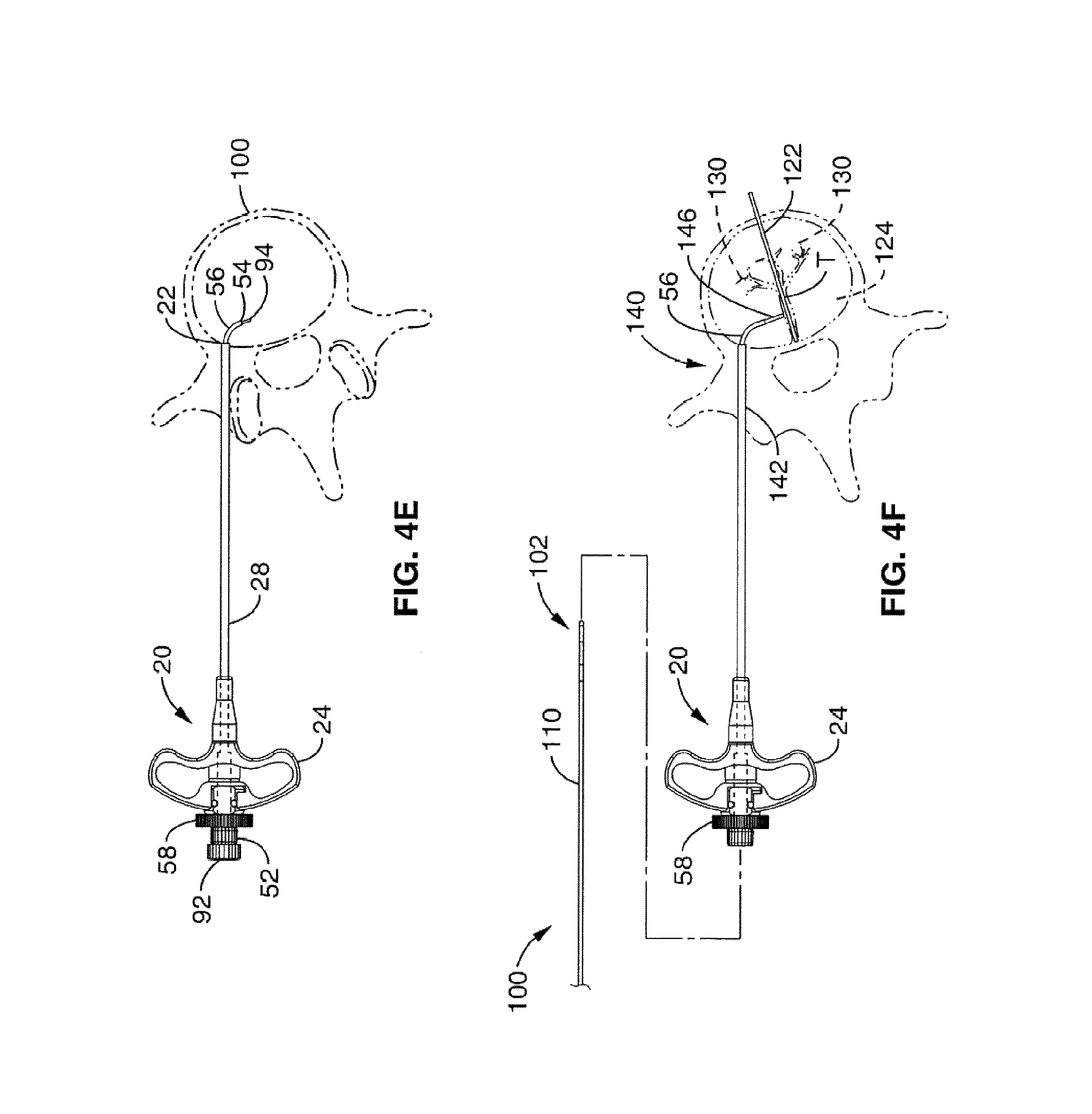
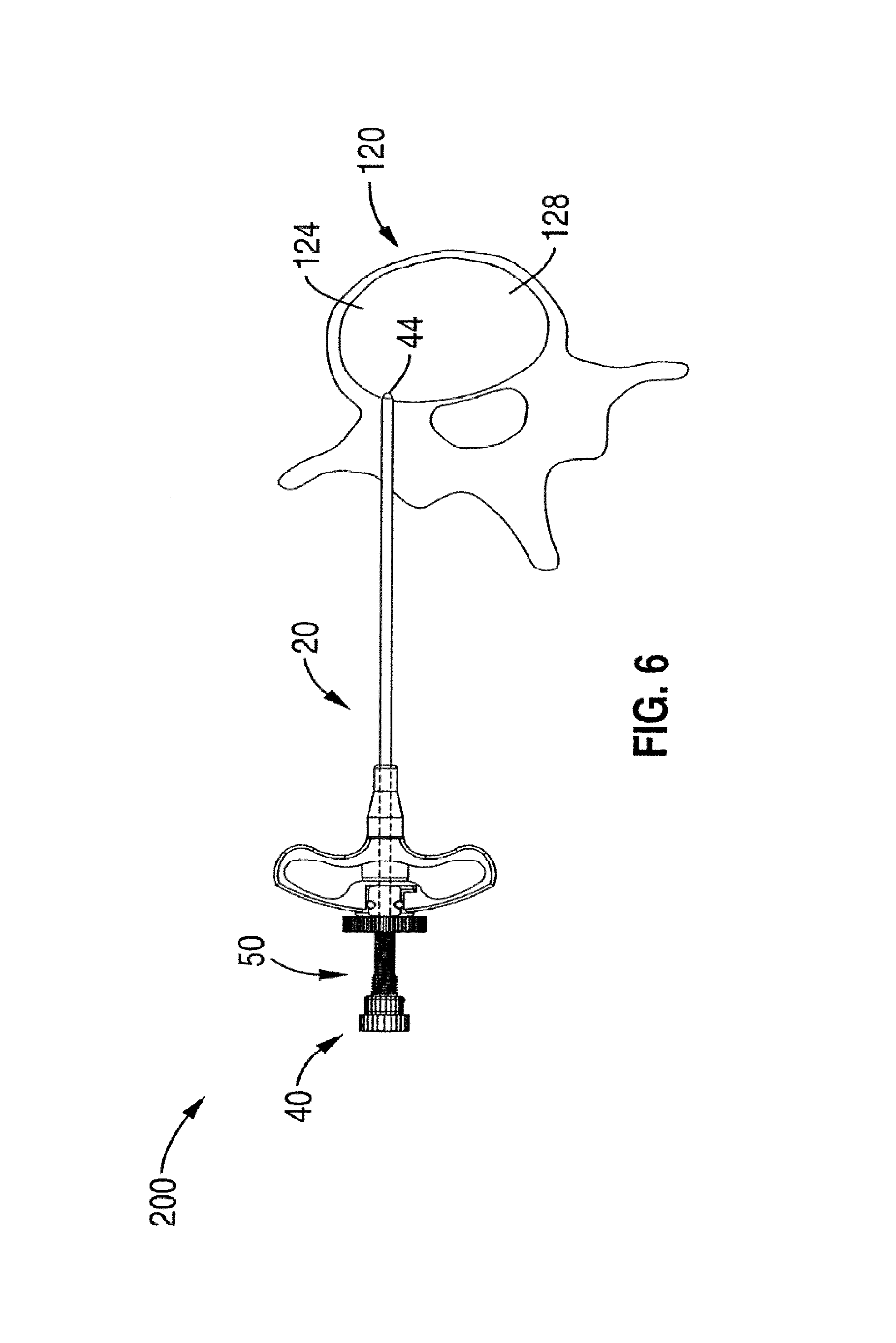
1. A method for channeling a path into bone to a treatment location in a body of a patient, comprising: selecting a set of treatment instruments out of a kit based on a diagnostic evaluation of the treatment location, the set of treatment instruments comprising an introducer, a curved cannula having a curvature selected based on the diagnostic evaluation, a channeling stylet, and a treatment device; inserting the introducer into a region of the bone near the treatment location, the introducer having a central channel and an opening at a distal tip of the introducer; delivering the curved cannula through said central channel of said introducer to said opening, extending the curved cannula past the opening at the distal tip of the introducer to generate a curved path in the bone; inserting the channeling stylet into the curved cannula, creating a linear channel starting at a distal end of the curved path formed by the curved cannula by extending a distal end of the channeling stylet out of an open distal tip of the curved cannula; removing the channeling stylet from the curved cannula; and delivering the treatment device through said curved cannula to the treatment location through the linear channel.
2. The method of claim 1, wherein inserting the introducer into the region of bone comprises: inserting a stylet into the introducer such that the stylet extends beyond the opening of the introducer; inserting the stylet and the introducer simultaneously into the region of bone such that the stylet pierces the bone as the introducer is being delivered to the treatment location.
3. The method of claim 1, wherein delivering the curved cannula through the central channel comprises: inserting a straightening stylet into a central passageway of the curved cannula; the straightening stylet comprising a rigid construction configured to straighten the curved cannula; inserting the straightening stylet and the curved cannula simultaneously into the introducer; and removing the straightening stylet from the curved cannula.
4. The method of claim 3: wherein the straightening stylet further comprises a sharp distal end to pierce the bone; and wherein the sharp distal end extends beyond the open distal tip of the curved cannula.
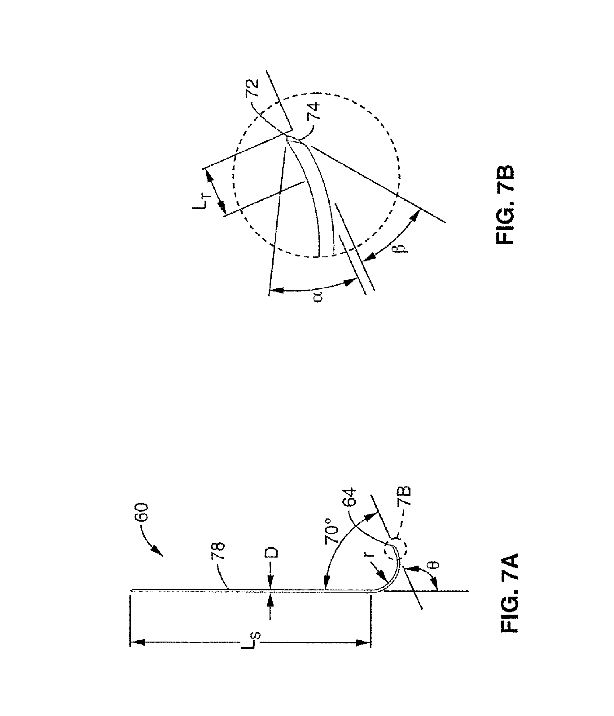
5. The method of claim 1, wherein extending the curved cannula past the opening at the distal tip of the introducer comprises: inserting a curved stylet into a central passageway of the curved cannula such that a distal tip of the curved stylet extends to at least the open distal tip of the curved cannula; and simultaneously extending the curved cannula and the curved stylet from the distal end of the introducer such that the curved stylet blocks the open distal tip of the curved cannula while being delivered into the bone.
6. The method of claim 5, further comprising removing the curved stylet from the curved cannula.
7. The method of claim 1, wherein the treatment location corresponds to a location of a portion of a basivertebral nerve of a vertebra, the method further comprising delivering treatment to the treatment location sufficient to denervate at least the portion of the basivertebral nerve.
8. The method of claim 7, wherein denervating the portion of the basivertebral nerve comprises delivering focused, therapeutic heating to the treatment location.
9. The method of claim 7, wherein denervating the portion of the basivertebral nerve comprises delivering an agent to the treatment location.
10. The method of claim 1, wherein the kit comprises a set of cannulas comprising one or more cannulas with distal tips having varying preformed curvatures.
11. The method of claim 7, wherein delivering treatment to the treatment location to denervate at least the portion of the basivertebral nerve comprises delivering radiofrequency energy to the treatment location sufficient to denervate at least the portion of the basivertebral nerve.
12. The method of claim 7, wherein delivering treatment to the treatment location to denervate at least the portion of the basivertebral nerve comprises delivering ultrasonic energy to the treatment location sufficient to denervate at least the portion of the basivertebral nerve.
13. A method for channeling a path into vertebral bone to a treatment location in a body of a patient, comprising: selecting a set of treatment instruments out of a kit based on a particular spine segment within which the vertebral bone is located, the set of treatment instruments comprising an introducer, a curved cannula having a curvature selected based on the particular spine segment, a channeling stylet, and a treatment device; inserting the introducer through a cortical bone region and into a cancellous bone region of the vertebral bone near the treatment location, wherein the introducer has a central channel along its longitudinal axis and an axial opening at a distal tip of the introducer; delivering the curved cannula through said central channel of the introducer to the axial opening at the distal tip of the introducer; extending the curved cannula past the axial opening at the distal tip of the introducer to generate a curved path toward the treatment location, wherein the curved cannula is extended through at least a portion of the cancellous bone region to a location near the treatment location; creating a linear channel starting at a distal end of the curved path formed by the curved cannula by inserting the channeling stylet within the curved cannula and extending a distal end of the channeling stylet out of an open distal tip of the curved cannula; removing the channeling stylet from the curved cannula; delivering a treatment probe through a central passageway in the curved cannula to the treatment location through the linear channel.
14. The method of claim 13, wherein the kit comprises a set of cannulas comprising one or more cannulas with distal tips having varying preformed curvatures.
15. The method of claim 13, wherein the treatment location comprises a basivertebral nerve of the vertebral bone.
16. The method of claim 15, wherein the treatment probe comprises a radiofrequency energy delivery probe.
17. The method of claim 15, wherein the treatment probe comprises an ultrasonic energy delivery probe.
18. The method of claim 15, wherein the treatment location is posterior to a basivertebral nerve junction.
19. The method of claim 13, wherein the step of inserting the introducer through the cortical bone region and into the cancellous bone region of the vertebral bone near the treatment location comprises: inserting a stylet into the introducer such that the stylet extends beyond the axial opening of the introducer; and inserting the stylet and introducer simultaneously into the vertebral bone such that the stylet pierces cancellous bone within the cancellous bone region as the introducer is being delivered toward the treatment location.
20. The method of claim 13, wherein the step of extending the curved cannula past the axial opening at the distal tip of the introducer comprises: inserting a curved stylet into the central passageway of the curved cannula such that a distal tip of the curved stylet extends to at least the open distal tip of the curved cannula; and simultaneously extending the curved cannula and the curved stylet from the distal end of the introducer such that the curved stylet blocks the open distal tip of the curved cannula while being delivered into the vertebral bone.
Description
STATEMENT REGARDING FEDERALLY SPONSORED RESEARCH OR DEVELOPMENT
Not Applicable
INCORPORATION-BY-REFERENCE OF MATERIAL SUBMITTED ON A COMPACT DISC
Not Applicable
NOTICE OF MATERIAL SUBJECT TO COPYRIGHT PROTECTION
A portion of the material in this patent document is subject to copyright protection under the copyright laws of the United States and of other countries. The owner of the copyright rights has no objection to the facsimile reproduction by anyone of the patent document or the patent disclosure, as it appears in the United States Patent and Trademark Office publicly available file or records, but otherwise reserves all copyright rights whatsoever. The copyright owner does not hereby waive any of its rights to have this patent document maintained in secrecy, including without limitation its rights pursuant to 37 C.F.R. .sctn. 1.14.
BACKGROUND OF THE INVENTION
1. Field of the Invention
This invention pertains generally to generating passageways through tissue, and more particularly to creating curved paths in bone.
2. Description of Related Art
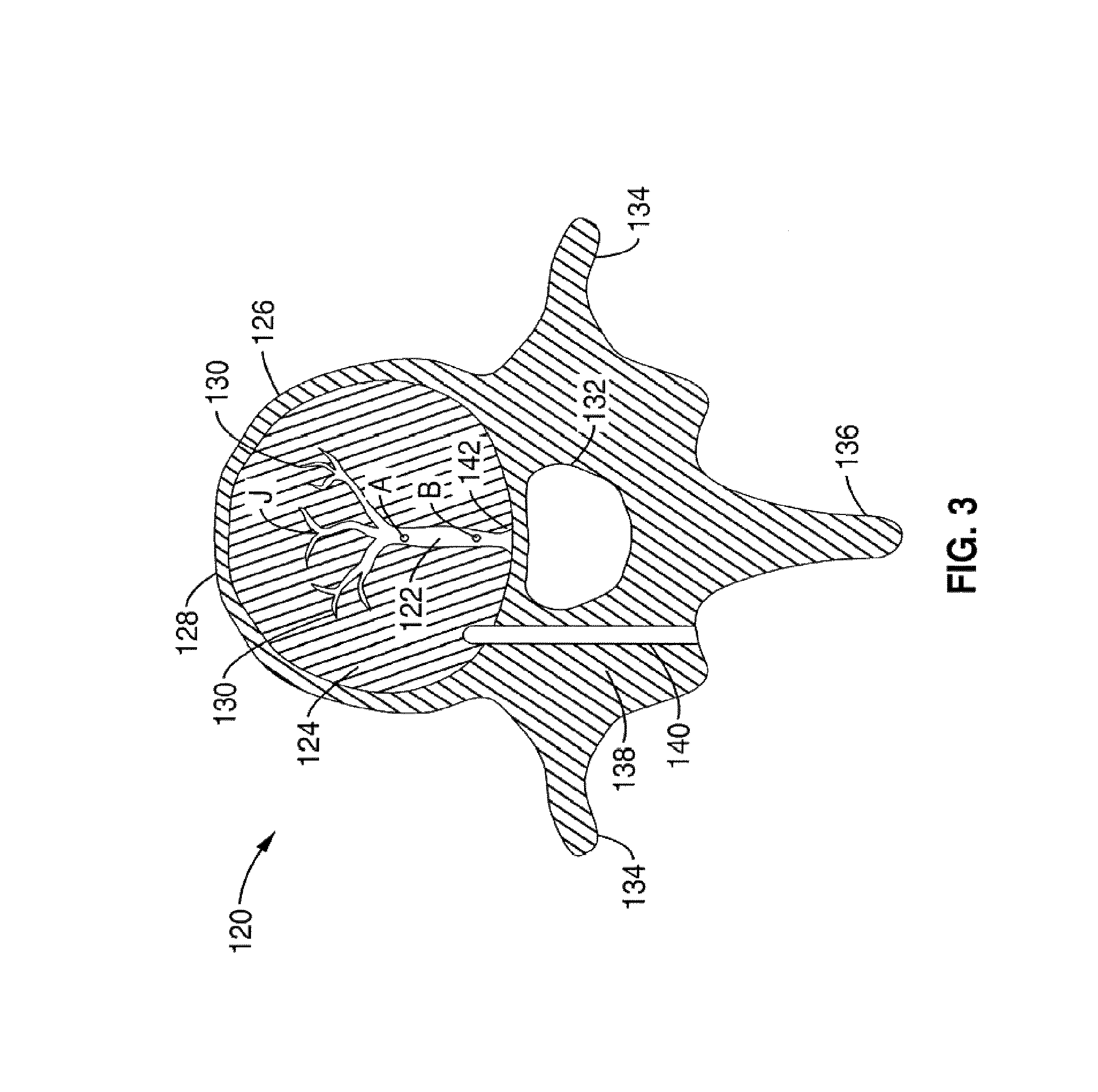
Recently, the technique of accessing the vertebral body through minimally invasive means has been developed through the surgical techniques used in vertebroplasty and kyphoplasty. Although accessing the vertebral segments of the spine through the pedicle and into the lateral/anterior section of the body of the vertebra is the primary method of placing a treatment device (e.g. a bone cement delivery device and/or an RF probe) into the vertebra, it is difficult to place a probe in the posterior midline section of the vertebra. Furthermore, accessing the posterior midline section of the S1 segment of the spine is difficult with a straight linear access route. A probe preferably needs to be capable of navigating to the posterior section of the S1 vertebral body as well as the same target area within a lumbar vertebral segment. In addition, it is contemplated that spinal segments in the cervical and thoracic spine may also be targeted.
In order to accurately and predictably place a treatment device in the posterior midline section of a lumbar vertebral body or S1 vertebral body, the device or probe needs to navigate to said area through varying densities of bone. However due to the varying densities of bone, it is difficult to navigate a probe in bone and ensure its positioning will be in the posterior midline section of the vertebral body.
Current techniques for tissue aspirations require a coaxial needle system that allows taking several aspirates through a guide needle without repositioning the guide needle. However the problem with this system is that after the first pass of the inner needle in to the lesion, subsequent passes tend of follow the same path within the mass, yielding only blood not diagnostic cells.
A scientific paper written by Kopecky et al., entitled "Side-Exiting Coaxial Needle for Aspiration Biopsy," describes the use of a side exiting coaxial needle to allow for several aspiration biopsies. The guide needle has a side hole 1 cm from the distal tip. When a smaller needle is advanced through this new guide needle, the smaller needle is deflected by a ramp inside the guide, causing the smaller needle to exit through the side hole. Although this side exiting needle is able to deflect a bone aspiration needle, it does not guarantee that the needle exits the side hole in a linear direction into the tissue site. Once the tissue aspiration needle exits the needle, it will deviate from a linear path depending on the density of the tissue and inherent material strength of the needle. This is an inherent problem the device is unable to overcome.
Accordingly, an object of the present invention is a system and method for generating a path in bone that predictably follows a predetermined curved path.
BRIEF SUMMARY OF THE INVENTION
The present invention is directed to systems and methods to deploy and navigate a flexible treatment instrument, such as an RF bipolar probe, within bone. Although the systems and methods described below are primarily directed to navigating bone through a vertebral member of the spine, and particularly to treat the BVN of a vertebral member, it is appreciated that the novel aspects of the present invention may be applied to any tissue segment of the body.
The first novel principle of this invention is the ability to navigate a curve or angle within varying densities of cancellous bone and create a straight channel at the end of the navigated curve or angle. Several systems are described.
One aspect is a method of therapeutically treating a vertebral body having an outer cortical bone region and an inner cancellous bone region, and a BVN having a trunk extending from the outer cortical bone region into the inner cancellous region and a branches extending from the trunk to define a BVN junction, comprising the steps of: a) inserting an energy device into the vertebral body, and b) exclusively depositing energy within the inner cancellous bone region of the vertebral body between, but exclusive of the BVN junction and the outer cortical bone region, to denervate the BVN.
In another aspect of the present invention, a tube-within-tube embodiment has a deployable curved Nitinol tube that deploys from a straight cannula. The Nitinol tube is pre-curved to create an angular range of approximately 0.degree. to approximately 180.degree., but more specifically from approximately 45.degree. to approximately 110.degree., when fully deployed from the straight cannula. The design of the curve is such that the flexible element (carrying the treatment device) can navigate through the angular range of deployment of the nitinol tube. The curved nitinol tube allows the flexible element to navigate through a curve within bone without veering off towards an unintended direction. Cancellous bone density varies from person to person. Therefore, creating a curved channel within varying density cancellous bone will generally not predictably or accurately support and contain the treatment device as it tries to navigate the curved channel. With the present invention, the flexible element is deployed into the bone through the curved Nitinol tube, which supports the element as it traverses through the curve. When it departs from the tube, it will do so in a linear direction towards the target zone. This design allows the user to predictably and accurately deploy the flexible element towards the target zone regardless of the density of the cancellous bone.
An aspect of the invention is a system for channeling a path into bone. The system comprises a trocar having a central channel and opening at its distal tip, and a cannula sized to be received in said central channel and delivered to said distal opening. The cannula has a deflectable tip with a preformed curve such that the tip straightens while being delivered through the trocar and regains its preformed curve upon exiting and extending past the distal opening of the trocar to generate a curved path in the bone corresponding to the preformed curve of the deflectable tip. The cannula comprises a central passageway having a diameter configured allow a treatment device to be delivered through the central passageway to a location beyond the curved path.
In one embodiment, the system further includes a straight stylet configured to be installed in the trocar, wherein the straight stylet comprises a sharp distal tip that is configured to extend beyond the distal opening of the trocar to pierce the bone as the trocar is being delivered to a treatment location within the bone.
The system may further include a straightening stylet configured to be installed in the cannula, wherein the straightening stylet comprising a rigid construction configured to straighten the distal tip of the cannula when positioned in the trocar.
In an alternative embodiment, the straightening stylet further comprises a sharp distal end to pierce the bone, and the straightening stylet and cannula are installed in the trocar in place of the straight stylet as the trocar is delivered into the bone.
In a preferred embodiment, the system further includes a curved stylet having an outer radius sized to fit within the central passageway of the curved cannula. The curved stylet is configured to be installed in the curved cannula while the curved cannula is extended past the distal opening of the trocar, the curved stylet configured to block the distal opening of the curved cannula while being delivered into the bone. Preferably, the curved stylet has a curved distal end corresponding to the curve of the curved cannula.
The curved stylet also has a sharp distal tip configured to extend past the curved cannula to pierce the bone as the cannula is delivered past the distal opening of the trocar. The curved stylet also preferably comprises an angled distal tip configured to further support and maintain the curved stylet radius as it is delivered past the distal opening of the trocar and into bone.
Preferably, the curved stylet and the curved cannula have mating proximal ends that align the curve of the curved stylet with the curve of the curved cannula.
In one embodiment, the system further includes a straight channeling stylet configured to be installed in the cannula after removing the curved stylet, wherein the straight channeling stylet is flexibly deformable to navigate the curved cannula yet retain a straight form upon exiting the curve cannula, and wherein straight channeling stylet has a length longer than the curved cannula such that it creates a linear path beyond the distal end of the curved cannula when fully extended.
Another aspect is method for channeling a path into bone to a treatment location in the body of a patient. The method includes the steps of inserting a trocar having a central channel and opening at its distal tip into a region of bone at or near the treatment location, and delivering a cannula through said central channel and to said distal opening, wherein the cannula comprises a deflectable tip with a preformed curve such that the tip straightens while being delivered through the trocar and regains its preformed curve upon exiting the trocar, and extending the cannula past the distal opening of the trocar to generate a curved path in the bone corresponding to the preformed curve of the deflectable tip. Finally, a treatment device is delivered through a central passageway in said cannula to the treatment location beyond the curved path.
In one embodiment, inserting a trocar into a region of bone comprises inserting a stylet into the trocar such that the stylet extends beyond the distal opening of the trocar, and inserting the stylet and trocar simultaneously into the region of bone such that the stylet pierces the bone as the trocar is being delivered to a treatment location.
In another embodiment, delivering a cannula through the central channel comprises inserting a straightening stylet into the central passageway of the cannula, wherein the straightening stylet comprises a rigid construction configured to straighten the curved distal tip of the cannula, and inserting the straightening stylet and straightened cannula simultaneously into the trocar.
In an alternative embodiment, the straightening stylet further comprises a sharp distal end to pierce the bone, wherein the straightening stylet and cannula are installed simultaneously along with the trocar as the trocar is delivered into the bone.
In yet another embodiment, extending the cannula past the distal opening is done by inserting a curved stylet into the central passageway of the curved cannula such that a distal tip of the curved stylet extends to at least the distal opening of the curved cannula, and simultaneously extending the curved cannula and curved stylet from the distal end of the trocar such that the curved stylet blocks the distal opening of the curved cannula while being delivered into the bone.
In a preferred embodiment, the curved stylet has a curved distal end corresponding to the curve of the curved cannula, and wherein the curved stylet reinforces the curved shape of the curved cannula as the curved cannula is extended past the distal opening of the trocar. The curved stylet has a sharp distal tip such that it is advanced within the central passageway so that the curved stylet extends past the distal opening of the curved cannula such that the curved stylet pierces the bone as the cannula is delivered past the distal opening of the trocar.
In a further step, the curved stylet is removed from the curved cannula, and a straight channeling stylet is inserted into the curved distal end of the cannula. The straight channeling stylet is flexibly deformable to navigate the curved cannula, yet retain a straight form upon exiting the curved cannula. The straight channeling stylet is longer than the curved cannula to create a linear channel beyond the distal tip of the curved cannula.
In a preferred embodiment, the trocar is inserted through a cortical bone region and into a cancellous bone region of a vertebrae, and the curved cannula is extended though at least a portion of the cancellous bone region to a location at or near the treatment location. A preferred treatment location comprises a BVN of the vertebrae, and treatment is delivered to the treatment location to denervate at least a portion of the BVN. In one embodiment, a portion of the BVN is denervated by delivering focused, therapeutic heating to an isolated region of the BVN. In another embodiment, a portion of the BVN comprises is denervated delivering an agent to the treatment region to isolate treatment to that region. Preferably, the treatment is focused on a location of the BVN that is downstream of one or more branches of the BVN.
Another aspect is a kit for channeling a path into bone. The kit includes a trocar having a central channel and opening at its distal tip, and a cannula selected from a set of cannulas sized to be received in said central channel and delivered to said distal opening. The cannula has a deflectable distal tip with a preformed curve such that the tip straightens while being delivered through the trocar and regains its preformed curve upon exiting and extending past the distal opening of the trocar to generate a curved path in the bone corresponding to the preformed curve of the deflectable tip. The cannula comprises a central passageway having a diameter configured allow a treatment device to be delivered through the central passageway to a location beyond the curved path, wherein the set of cannulas comprises one or more cannulas that have varying preformed curvatures at the distal tip.
In a preferred embodiment, the one or more cannulas have a varying preformed radius at the distal tip. In addition, the one or more cannulas each have distal tips that terminate at varying angles with respect to the central channel of the trocar. The length of the distal tips may also be varied. The angle of the distal with respect to the central channel of the trocar may vary from 0 degrees to 180 degrees.
The kit may further include a straight stylet configured to be installed in the trocar, the straight stylet comprising a sharp distal tip that is configured to extend beyond the distal opening of the trocar to pierce the bone as the trocar is being delivered to a treatment location within the bone.
In a preferred embodiment, the kit includes a set of curved stylets having an outer radius sized to fit within the central passageway of the curved cannula, wherein each curved stylet is configured to be installed in the curved cannula while the curved cannula is extended past the distal opening of the trocar. The curved stylet is configured to block the distal opening of the curved cannula while being delivered into the bone. Each curved stylet has a varying curved distal end corresponding to the curve of a matching curved cannula in the set of curved cannulas. The curved stylet has a sharp distal tip configured to extend past the curved cannula to pierce the bone as the cannula is delivered past the distal opening of the trocar.
In another embodiment, the kit includes a set of straight channeling stylets wherein one of the set of stylets is configured to be installed in the cannula after removing the curved stylet. The straight channeling stylet is flexibly deformable to navigate the curved cannula yet retain a straight form upon exiting the curve cannula. Each of the straight channeling stylets has a varying length longer than the curved cannula such that the straight channeling stylet creates a predetermined-length linear path beyond the distal end of the curved cannula when fully extended.
Further aspects of the invention will be brought out in the following portions of the specification, wherein the detailed description is for the purpose of fully disclosing preferred embodiments of the invention without placing limitations thereon.
BRIEF DESCRIPTION OF THE SEVERAL VIEWS OF THE DRAWING(S)
The invention will be more fully understood by reference to the following drawings which are for illustrative purposes only:
FIG. 1 is a system for generating a curved path in bone according to the present invention.
FIG. 2 is a sectional view of the system of FIG. 1
FIG. 3 illustrates a sectioned view of a vertebral body with a path bored through the cortical shell.
FIGS. 4A-F illustrate a method for accessing the BVN with the system of the present invention.
FIG. 5 shows an alternative system for generating a curved path in bone according to the present invention.
FIG. 6 shows the system of FIG. 5 being installed in a vertebral body.
FIGS. 7A-7B show a curved stylet in accordance with the present invention.
DETAILED DESCRIPTION OF THE INVENTION
Referring more specifically to the drawings, for illustrative purposes the present invention is embodied in the apparatus generally shown in FIG. 1 through FIG. 7B. It will be appreciated that the apparatus may vary as to configuration and as to details of the parts, and that the method may vary as to the specific steps and sequence, without departing from the basic concepts as disclosed herein.
FIGS. 1 and 2 illustrate a first embodiment of the present invention comprising a system or kit 10 for forming a path through bone. The system comprises a needle trocar 20 (the main body of the instrument set). The trocar 20 comprises an elongate shaft 28 having a handle 24 at its proximal end 32 and a central lumen 36 passing through to the distal end 22 of the trocar 20. The central lumen 36 is generally sized to allow the other instruments in the system 10 to be slideably introduced into the patient to a treatment region. System 10 further comprises a straight stylet 80 having a sharp-tipped needle 84 at its distal end that is used with the needle trocar 20 to create the initial path through the soft tissue and cortical shell to allow access to the cancellous bone, a curved cannula 50 that is used to create/maintain the curved path within the bone/tissue. A straightening stylet 40 is used to straighten out the curve and load the curved cannula 50 into the needle trocar 20. A curved stylet 60 is used in conjunction with the curved cannula 50 to create the curved path within the bone/tissue, and a channeling stylet 90 is used to create a working channel for a treatment device (such as RF probe 100) beyond the end of the curved path created by the curved cannula 50.
The surgical devices and surgical systems described may be used to deliver numerous types of treatment devices to varying regions of the body. Although the devices and systems of the present invention are particularly useful in navigating through bone, it is appreciated that they may also be used to navigate through soft tissue, or through channels or lumens in the body, particularly where one lumen may branch from another lumen.
The following examples illustrate the system 10 applied to generating a curve bone path in the vertebral body, and more particularly for creating a bone path via a transpedicular approach to access targeted regions in the spine. In particular, the system 10 may be used to deliver a treatment device to treat or ablate intraosseous nerves, and in particular that basivertebral nerve (BVN). Although the system and methods provide significant benefit in accessing the BVN, it is appreciated that the system 10 of the present invention may similarly be used to create a bone path in any part of the body.
FIG. 3 illustrates a cross-sectional view of a vertebra 120. Recently, the existence of substantial intraosseous nerves 122 and nerve branches 130 within human vertebral bodies ("basivertebral nerves") have been identified. The basivertebral nerve 122 has at least one exit 142 point at a location along the nerve 122 where the nerve 122 exits the vertebral body 126 into the vertebral foramen 132.
Preferably, the basivertebral nerves are at, or in close proximity to, the exit point 142. Thus, the target region of the BVN 122 is located within the cancellous portion 124 of the bone (i.e., to the interior of the outer cortical bone region 128), and proximal to the junction J of the BVN 122 having a plurality of branches 130 (e.g. between points A and B along nerve 122). Treatment in this region is advantageous because only a single portion of the BVN 122 need be effectively treated to denervate or affect the entire system. Typically, treatment in accordance with this embodiment can be effectuated by focusing in the region of the vertebral body located between 60% (point A) and 90% (point B) of the distance between the anterior and posterior ends of the vertebral body. In contrast, treatment of the BVN 122 in locations more downstream than the junction J require the denervation of each branch 130.
In one approach for accessing the BVN, the patient's skin is penetrated with a surgical instrument which is then used to access the desired basivertebral nerves, i.e., percutaneously. In one embodiment, a transpedicular approach is used for penetrating the vertebral cortex to access the BVN 122. A passageway 140 is created between the transverse process 134 and spinous process 136 through the pedicle 138 into the cancellous bone region 124 of the vertebral body 126 to access a region at or near the base of the nerve 122. It is appreciated that a postereolateral approach (not shown) may also be used for accessing the nerve.
FIGS. 4A-F illustrate a preferred method for accessing the BVN with the system 10 of the present invention. First, the straight stylet 80 is inserted in aperture 26 at the proximal end 32 of needle trocar 20. The straight stylet 80 is advanced down the central lumen 36 (see FIG. 2) of the trocar 20 until the proximal stop 82 abuts against handle 24 of the trocar 20, at which point the distal tip 84 of straight stylet protrudes out of the distal end 22 of the trocar 20. The tip 84 of the straight stylet 80 preferably comprises a sharp tip for piercing soft tissue and bone.
Referring now to FIG. 4A, the assembly (trocar 20 and straight stylus 80) is advanced through soft tissue to the surface of the bone. Once the proper alignment is determined, the assembly is advanced through the cortical shell of pedicle 138 and into the cancellous interior 124 of the bone.
After the proper depth is achieved, the straight stylet 80 is removed from the trocar 20, while the trocar 20 remains stationary within the vertebrae 120. The straightening stylet 40 is inserted into proximal aperture 53 (see FIG. 2) of the curved cannula 50 and advanced along the central lumen of the curved cannula 50 until the stop 42 of the stylet 40 abuts up to the proximal end 52 of the curved cannula. This forces the distal tip of the straight stylet through the curved section 56 of the curved cannula 50 to straighten out the curved section 56. It is contemplated that the straight stylet comprise a hard, non-compliant material and the distal end of the curved cannula 50 a compliant, yet memory retaining material (e.g. Nitinol, formed PEEK, etc.) such that the curved section 56 yields to the rigidity of the straightening stylet 40 when installed, yet retains its original curved shape when the stylet 40 is removed.
As shown in FIG. 4B, once the straightening stylet 40 is secure and the curved cannula 50 is straight, they are inserted into the needle trocar 20 and secured. Proper alignment (e.g. prevent rotation, orient curve direction during deployment) is maintained by aligning a flat on the upper portion 58 of the curved cannula 50 to an alignment pin secured perpendicularly into the needle trocar 20 handle 24. Once the curved cannula 50 is secure, the straightening stylet 40 is removed, while the curved cannula 50 remains stationary within the trocar 20.
Referring to FIG. 4C, the curved stylet 60 is then straightened out by sliding the small tube 68 proximally to distally on its shaft towards the distal tip 64 or from the distal tip 64 proximally on its shaft towards the proximal end 62. Once the curved distal tip 66 is straightened out and fully retracted inside the small tube 68, the curved stylet 60 is inserted into the proximal aperture 53 of the curved cannula 50, which still resides inside the needle trocar 20. As the curved stylet 60 is advanced into the curved cannula 50, the small tube 68 is met by a stop 55 (see FIG. 4C). As the curved stylet 60 continues to advance the small tube 68 is held inside the handle of the curved cannula 50. This allows the curve of the stylet 60 to be exposed inside the curved cannula 50. To create the maximum force the curve of the two parts (50 & 60) must be aligned. To ensure alignment the cap on the curved stylet 60 has an alignment pin 70 which engages with an alignment notch on the proximal end 52 of the curved cannula 50.
Once the stylet 60 is fully seated and aligned with the curved cannula 50 the tip of the curved stylet 60 will protrude from the tip of the curved cannula 50 by about 1/16 to 3/16 inches. This protrusion will help to drive the curve in the direction of its orientation during deployment.
Referring now to FIG. 4D, with the curved stylet 60 and the curved cannula 50 engaged, the locking nut 58 at the top of the curved cannula 50 is rotated counter clockwise to allow the cannula 50 and curved stylet 60 to be advanced with relation to the needle trocar 20 such that the proximal end 52 abuts against 58, advancing the curved cannula 50 and curved stylet 60 beyond the distal opening of trocar 20 to generate a curved path in the cancellous bone region 124. As the curved cannula 50 and curved stylet 60 are advanced they will preferably curve at a radius of 0.4 to 1.0 inches through cancellous bone and arc to an angle between 5 and 110 degrees. Once the curved cannula 50 and curved stylet 60 are deployed to the intended angle, the locking nut at the top of the curved cannula 50 is engaged with the needle trocar 20 to stop any additional advancement of the curved stylet cannula assembly.
FIGS. 7A-7B illustrate the tip of the curved stylet 60, which has been formed with two angles. To help the curve deployment in the proper direction the curved section 66 of the curved stylet 60 is shaped in a predetermined orientation. The angle on the inside of the curve 72 is less than the angle on the outside of the curve 74. This disparity in angle helps the stylet cannula assembly 50 & 60 curve in the bone as bone pushes against outside curve face 74 ensuring the curve radius is maintained during deployment.
Referring now to FIG. 4E, the curved stylet 60 is then removed and replaced by the channeling stylet 90. The tip 94 of the channeling stylet 90 is advanced beyond the end 54 of the curved cannula 50 towards the intended target treatment zone.
Referring now to FIG. 4F, once the channeling stylet 90 reaches the target treatment zone, it is removed creating a working channel 146. Channel 140 will generally have a first section 142 that crosses the cortical bone of the pedicle 138, followed by a curved path 144. These sections are occupied by curved cannula 50 such that a treatment device fed through the cannula 50 will have to follow the curve of the cannula 50 and not veer off in another direction. The channel may further comprise the linear extension 146 in the cancellous bone 124 to further advance the treatment device toward the treatment site T.
With the trocar 20 and curved cannula 50 still in place, a treatment device (e.g. treatment probe 100 shown in FIG. 2, with an active element 102 on the distal end 104 of elongate flexible catheter 110 is delivered to the target treatment location T to perform a localized treatment.
In a preferred embodiment, the active element 102 is delivered to the treatment site and activated to delivery therapeutic treatment energy. The treatment probe may comprise an RF delivery probe having bipolar electrodes 106 and 108 that deliver a therapeutic level of heating to stimulate or ablate the nerve 122.
It is appreciated that any number of treatment modalities may be delivered to the treatment site for therapeutic treatment. For example, treatment may be affected by monopolar or tripolar RF, ultrasound, radiation, steam, microwave, laser, or other heating means. Additionally, the treatment device may comprise a fluid delivery catheter that deposits an agent, e.g. bone cement, or other therapeutic agent, to the treatment site T. Alternatively, cryogenic cooling may be delivered for localized treatment of the BVN. Furthermore, treatment may be affected by any mechanical destruction and or removal means capable of severing or denervating the BVN. For example, a cutting blade, bur or mechanically actuated cutter typically used in the art of orthoscopic surgery may be used to affect denervation of the BVN.
In addition to or separate from treating the BVN, a sensor may be delivered to the region to preoperatively or postoperatively measure nerve conduction at the treatment region. In this configuration, the sensor may be delivered on a distal tip of a flexible probe that may or may not have treatment elements as well.
The goal of the treatment may be ablation, or necrosis of the target nerve or tissue, or some lesser degree of treatment to denervate the BVN. For example, the treatment energy or frequency may be just sufficient to stimulate the nerve to block the nerve from transmitting signal (e.g. signals indicating pain).
Once the treatment is complete, the probe 100 is withdrawn. The curved cannula 50 is then withdrawn into the needle trocar 20. The needle trocar 20 with the curved cannula 50 is then removed and the access site is closed as prescribed by the physician.
In the above system 10, the design of the curved sections 56 and 66 of the curved cannula 50 and curved stylet 60, respectively, is such that the flexible element (e.g. carrying the treatment device) can navigate through the angular range of deployment of the Nitinol tube of the curved cannula 50. The curved nitinol tube of the curved cannula 50 allows the flexible element to navigate through a curve within bone without veering off towards an unintended direction. Cancellous bone density varies from person to person. Therefore, creating a curved channel within varying density cancellous bone 124 will generally not predictably or accurately support and contain the treatment device as it tries to navigate the curved channel.
With the system 10 of the present invention, the treatment device 100 is deployed into the bone through the curved Nitinol tube of the curved cannula 50, which supports the element as it traverses through the curve. When it departs from the tube, it will do so in a linear direction along path 146 towards the target zone. This allows the user to predictably and accurately deploy the treatment device towards the target zone T regardless of the density of the cancellous bone.
In some embodiments, a radius of curvature that is smaller than that which can be achieved with a large diameter Nitinol tube may be advantageous. To achieve this, the curved tube of the curved cannula 50 may take one of several forms. In one embodiment, the tube 50 is formed from a rigid polymer that can be heat set in a particular curve. If the polymer was unable to hold the desired curve, an additional stylet (e.g. curved stylet 60) of Nitinol, or other appropriate material, may also be used in conjunction with the polymer tube to achieve the desired curve. This proposed combination of material may encompass and number or variety of materials in multiple different diameters to achieve the desired curve. These combinations only need to ensure that the final outside element (e.g. trocar 20) be "disengageable" from the internal elements and have an inner diameter sufficient to allow the desired treatment device 100 to pass to the treatment region T.
In an alternative embodiment, of the curved cannula 50 may comprise a Nitinol tube having a pattern of reliefs or cuts (not shown) in the wall of the tube (particularly on the outer radius of the bend). The pattern of cuts or reliefs would allow the tube to bend into a radius tighter than a solid tube could without compromising the integrity of the tubing wall.
FIG. 5 illustrates a second embodiment of the system or kit 200 of the present invention that may be used to reduce the number of steps required for the procedure. The second embodiment includes a needle trocar 20, straightening stylet 40, used with the needle trocar 20 and the curved cannula 50 to create the initial path through the soft tissue and cortical shell to allow access to the cancellous bone, curved stylet 60 used in conjunction with the curved cannula 50 to create the curved path within the bone/tissue, and channeling stylet 90 used to create a working channel for the probe beyond the end of the curved path created by the curved stylet.
In one method according to the present invention, the straightening stylet 40 is inserted into the curved cannula 50 and secured. In this embodiment, the straightening stylet 40 has a sharp tip 46 designed to penetrate bone. Once the straightening stylet 40 is secure and the curved cannula 50 is straight, they are inserted into the needle trocar 20 and secured. In this embodiment, the curved cannula 50 and straightening stylet 40 are inserted into the shaft 28 of the trocar 20 only as far as to have sharp tip 46 of the straightening stylet 40 protrude from the distal end 22 of the trocar 20. Proper alignment is maintained by aligning a flat on the upper portion of the curved cannula 50 with a pin secured perpendicularly into the needle trocar 20 handle.
Referring now to FIG. 6, once the curved cannula 50 is secure, the assembly (trocar 20, curved cannula 50, and straightening stylet 40) is advanced through soft tissue to the surface of the bone. After finding the proper alignment at the pedicle 138 of vertebrae 120, the assembly (trocar 20, curved cannula 50, and straightening stylet 40) is advanced through the cortical shell 128 and into the cancellous interior 124 of the bone.
After the proper depth is achieved, the straightening stylet 40 is removed. The curved stylet 60 is then straightened out by sliding the small tube 68 on its shaft towards the distal tip 64. The curved distal tip 66 is straightened out and fully retracted inside the small tube 68, and then the curved stylet 60 is inserted into the curved cannula 50 which still resides inside the needle trocar 20. Once the curved stylet 60 is inserted into the curved cannula 50, the small tube 68 is met by a stop 55 (see FIG. 4C). As the curved stylet 60 continues to advance, the small tube 68 is held inside the handle of the curved cannula 50. This allows the curve of the stylet 60 to be exposed inside the curved cannula 50.
To create the maximum force, it is preferred that the curve of the two parts (50 & 60) are aligned. To ensure alignment the cap on the curved stylet 60 has an alignment pin, which engages with a notch on the top of the curved cannula 50.
When the stylet 60 is fully seated and aligned with the curved cannula 50, the tip of the curved stylet 60 will protrude from the tip of the curved cannula 50 by about 1/16 to 3/16 inches. This protrusion will help to drive the curved cannula 50 in the direction of its orientation during deployment. Once the curved stylet 60 and the curved cannula 50 are engaged, the lock nut at the top of the curved cannula 50 is rotated counter clockwise to allow the cannula 50 and stylet 60 to be advanced with relation to the needle trocar 20 (as shown in FIG. 4D). As the curved cannula and stylet are advanced they generate a curved path toward the treatment location T. Once the curved cannula 50 and stylet 60 are deployed to the intended angle, the lock nut at the top of the curved cannula 50 is engaged with the needle trocar 20 to stop any additional advancement of the curved stylet cannula assembly.
The curved stylet 60 is then removed and replaced by the channeling stylet 90. The channeling stylet 90 is advanced beyond the end of the curved cannula 50 (see FIG. 4E) towards the intended target treatment zone creating a working channel for the active element to be inserted. Once the channeling stylet 80 reached the target treatment zone it is removed and replaced by the treatment device 100, which is delivered to the treatment site T and activated.
Once the treatment is complete, the treatment device 100 is withdrawn. The curved cannula 50 is then withdrawn into the needle trocar 20. The needle trocar 20 with the curved cannula 50 is then removed and the access site is closed as prescribed by the physician.
FIGS. 7A and 7B illustrate detail views of a Nitinol wire for the curved stylet 60 (proximal end not shown). The wire comprises a shaft 78 having constant diameter D and a length L.sub.s that may vary according to the application and desired depth to the treatment location. The wire has a preformed distal tip that is curved to have a radius r that redirects the distal tip 64 at an angle .THETA. with the shaft. As shown in FIG. 7A, angle .THETA. is shown to be approximately 110.degree.. However, it is appreciated that the preformed tip may have an angle ranging from a few degrees (slight deflection off axis), to up to 180.degree. (e.g. directing back toward the proximal end).
As shown in FIG. 7B detailing the distal tip 64, the tip may have a distal extension L.sub.T that extends away from the shaft 78. To promote channeling along a path that follows radius r, the distal tip 64 is configured with a dual-plane bevels 74 and 72. Plane 74 is offset at angle .beta., and plane 72 is offset at angle .alpha.. This configuration of the leading--allows for the stylet and/or curved cannula to travel through bone in a path correlating to the specified curve in the stylet and/or cannula.
In the example illustrated in FIGS. 7A and 7B, the curved stylet 60 has a shaft length L.sub.s of approximately 3.6 in., diameter D of approximately 0.040 in., and a distal tip length L.sub.T of 0.125 in., radius r of 0.40 in., and angle .beta.=35.degree. and angle .alpha.=31.degree.. It should be noted that the above dimensions are for illustration only, and may vary depending on the anatomy an tissue type.
It is appreciated that all the above embodiments may be provided as a kit of instruments to treat different regions of the body. For example, the location, orientation and angle of the treatment device with respect to the trocar 20 may be varied by providing a set of instruments at varying increments. This may be achieved by varying the curvature (56, 66) in the curved cannula 50 and curved stylet 60. The curvature may be varied by varying the radius of curvature r, the insertion depth (shaft length L.sub.s and tip length L.sub.T, and/or the final exit angle .THETA. with respect to the trocar 20 central bore. Thus, the physician may select a different kit for treating a lumber spine segment as opposed to a cervical spine segment, as the anatomy will dictate the path that needs to be channeled.
Thus, when treating different spine segments, a set out of the kit may be selected to match the vertebra (or other region being treated). For example, delivering the treatment device at or near the BVN junction for a lumbar vertebra may have a different angle than for a cervical vertebra, and may vary from patient to patient. The set may be selected from the kit intra-operatively, or from a pre-surgery diagnostic evaluation (e.g. radiographic imaging of the target region).
It is appreciated that each of the instruments in the embodiments 100 and 200 detailed above may have any length, shape, or diameter desired or required to provide access to the treatment region (e.g. intraosseous nerve trunk) thereby facilitating effective treatment of the target region. For example, the size of the intraosseous nerve to be treated, the size of the passageway in the bone (e.g. pedicle 138) for accessing the intraosseous nerve, and the location of the bone, and thus the intraosseous nerve, are factors that that may assist in determining the desired size and shape of the individual instruments.
The systems 100, 200 described above may be used with a number of different treatment modalities for therapeutic treatment of the target region. For example, in one embodiment, it is desirable to operate the treatment device 100 in a manner that ablates the tissue of the target region (e.g. BVN) to produce as described in U.S. Pat. No. 6,699,242, herein incorporated by reference in its entirety.
In another embodiment, the treatment device is configured to deliver therapeutic treatment that is targeted to block nerve conduction without ablating the nerve, i.e. thermal treatment is delivered to the nerve (e.g. via thermal therapy, agent or the like) that results in denervation of the BVN without necrosis of tissue. This may be achieved via delivery of a lesser amount of energy or agent to the tissue site (either in the form of less exposure time, concentration, intensity, etc.) than is required for ablation, but an amount sufficient to achieve some amount of temporary or permanent denervation.
As can be seen, therefore, the present invention includes the following inventive embodiments among others:
1. A system for channeling a path into bone, comprising: a trocar having a central channel and opening at its distal tip; and a curved cannula sized to be received in said central channel and delivered to said distal opening; the curved cannula having a deflectable tip with a preformed curve such that the tip straightens while being delivered through the trocar and regains its preformed curve upon exiting and extending past the distal opening of the trocar to generate a curved path in the bone corresponding to the preformed curve of the deflectable tip; wherein the curved cannula comprises a central passageway having a diameter configured allow a treatment device to be delivered through the central passageway to a location beyond the curved path.
2. A system as recited in embodiment 2, further comprising: a straight stylet configured to be installed in the trocar; the straight stylet comprising a sharp distal tip that is configured to extend beyond the distal opening of the trocar to pierce the bone as the trocar is being delivered to a treatment location within the bone.
3. A system as recited in embodiment 2, further comprising: a straightening stylet configured to be installed in the curved cannula; the straightening stylet comprising a rigid construction configured to straighten the distal tip of the curved cannula when positioned in the trocar.
4. A system as recited in embodiment 3, wherein the straightening stylet further comprises a sharp distal end to pierce the bone; and wherein the straightening stylet and curved cannula are configured to be installed in the trocar in place of the straight stylet as the trocar is delivered into the bone.
5. A system as recited in embodiment 1, further comprising: a curved stylet having an outer radius sized to fit within the central passageway of the curved cannula; wherein the curved stylet is configured to be installed in the curved cannula while the curved cannula is extended past the distal opening of the trocar, the curved stylet configured to block the distal opening of the curved cannula while being delivered into the bone.
6. A system as recited in embodiment 5, wherein the curved stylet has a curved distal end corresponding to the curve of the curved cannula.
7. A system as recited in embodiment 5, wherein the curved stylet has a sharp distal tip configured to extend past the curved cannula to pierce the bone as the cannula is delivered past the distal opening of the trocar.
8. A system as recited in embodiment 7, wherein the curved stylet and the curved cannula have mating proximal ends that align the curve of the curved stylet with the curve of the curved cannula.
9. A system as recited in embodiment 5, further comprising a straight channeling stylet configured to be installed in the cannula after removing the curved stylet; wherein the straight channeling stylet is flexibly deformable to navigate the curved cannula yet retain a straight form upon exiting the curve cannula; wherein straight channeling stylet has a length longer than the curved cannula such that it creates a linear path beyond the distal end of the curved cannula when fully extended.
10. A method for channeling a path into bone to a treatment location in the body of a patient, comprising: inserting a trocar into a region of bone near the treatment location; the trocar having a central channel and opening at its distal tip; and delivering a cannula through said central channel and to said distal opening; wherein the cannula comprises a deflectable tip with a preformed curve such that the tip straightens while being delivered through the trocar and regains its preformed curve upon exiting the trocar; extending the cannula past the distal opening of the trocar to generate a curved path in the bone corresponding to the preformed curve of the deflectable tip; delivering a treatment device through a central passageway in said cannula having to the treatment location beyond the curved path.
11. A method as recited in embodiment 10, wherein inserting a trocar into a region of bone comprises inserting a stylet into the trocar such that the stylet extends beyond the distal opening of the trocar; and inserting the stylet and trocar simultaneously into the region of bone such that the stylet pierces the bone as the trocar is being delivered to a treatment location.
12. A method as recited in embodiment 10, wherein delivering a cannula through the central channel comprises: inserting a straightening stylet into the central passageway of the cannula; the straightening stylet comprising a rigid construction configured to straighten the curved distal tip of the cannula; and inserting the straightening stylet and straightened cannula simultaneously into the trocar.
13. A method as recited in embodiment 12, wherein the straightening stylet further comprises a sharp distal end to pierce the bone; and wherein the straightening stylet and cannula are installed simultaneously along with the trocar as the trocar is delivered into the bone.
14. A method as recited in embodiment 10, wherein extending the cannula past the distal opening comprises: inserting a curved stylet into the central passageway of the curved cannula such that a distal tip of the curved stylet extends to at least the distal opening of the curved cannula; simultaneously extending the curved cannula and curved stylet from the distal end of the trocar such that the curved stylet blocks the distal opening of the curved cannula while being delivered into the bone.
15. A method as recited in embodiment 14, wherein the curved stylet has a curved distal end corresponding to the curve of the curved cannula; and wherein the curved stylet reinforces the curved shape of the curved cannula as the curved cannula is extended past the distal opening of the trocar.
16. A method as recited in embodiment 14, wherein the curved stylet has a sharp distal tip; wherein curved stylet is advanced within the central passageway so that the curved stylet extends past the distal opening of the curved cannula such that the curved stylet pierces the bone as the cannula is delivered past the distal opening of the trocar.
17. A method as recited in embodiment 14, further comprising: removing the curved stylet from the curved cannula; inserting a straight channeling stylet into the curved distal end of the cannula; wherein the straight channeling stylet is flexibly deformable to navigate the curved cannula yet retain a straight form upon exiting the curved cannula; wherein the straight channeling stylet is longer than the curved cannula to create a linear channel beyond the distal tip of the curved cannula.
18. A method as recited in embodiment 10, wherein the trocar is inserted through a cortical bone region and into a cancellous bone region of a vertebrae, and wherein the curved cannula is extended though at least a portion of the cancellous bone region to a location at or near the treatment location.
19. A method as recited in embodiment 18, wherein the treatment location comprises a BVN of the vertebrae, the method further comprising: delivering treatment to the treatment location to denervate at least a portion of the BVN.
20. A method as recited in embodiment 19, wherein denervating a portion of the BVN comprises delivering focused, therapeutic heating to an isolated region of the BVN.
21. A method as recited in embodiment 19, wherein denervating a portion of the BVN comprises delivering an agent to the treatment region to isolate treatment to that region.
22. A method as recited in embodiment 19, wherein the treatment is focused on a location of the BVN that is downstream of one or more branches of the BVN.
23. A kit for channeling a path into bone, comprising: a trocar having a central channel and opening at its distal tip; and a cannula selected from a set of cannulas sized to be received in said central channel and delivered to said distal opening; the cannula having a deflectable distal tip with a preformed curve such that the tip straightens while being delivered through the trocar and regains its preformed curve upon exiting and extending past the distal opening of the trocar to generate a curved path in the bone corresponding to the preformed curve of the deflectable tip; wherein the cannula comprises a central passageway having a diameter configured allow a treatment device to be delivered through the central passageway to a location beyond the curved path; wherein the set of cannulas comprises one or more cannulas that have varying preformed curvatures at the distal tip.
24. A kit as recited in embodiment 23, wherein the one or more cannulas have a varying preformed radius at the distal tip.
25. A kit as recited in embodiment 23, wherein the one or more cannulas each have distal tips that terminate at varying angles with respect to the central channel of the trocar.
26. A kit as recited in embodiment 25, wherein the angle of the distal tip with respect to the central channel of the trocar varies from approximately 45.degree. to approximately 110.degree..
27. A kit as recited in embodiment 23, further comprising: a straight stylet configured to be installed in the trocar; the straight stylet comprising a sharp distal tip that is configured to extend beyond the distal opening of the trocar to pierce the bone as the trocar is being delivered to a treatment location within the bone.
28. A kit as recited in embodiment 23, further comprising: a set of curved stylets having an outer radius sized to fit within the central passageway of the curved cannula; wherein each curved stylet is configured to be installed in the curved cannula while the curved cannula is extended past the distal opening of the trocar; wherein the curved stylet configured to block the distal opening of the curved cannula while being delivered into the bone; and wherein each curved stylet has a varying a curved distal end corresponding to the curve of a matching curved cannula in the set of curved cannulas.
29. A kit as recited in embodiment 28, wherein the curved stylet has a sharp distal tip configured to extend past the curved cannula to pierce the bone as the cannula is delivered past the distal opening of the trocar.
30. A kit as recited in embodiment 28, wherein the curved stylet and the curved cannula have mating proximal ends that align the curve of the curved stylet with the curve of the curved cannula.
31. A kit as recited in embodiment 28, further comprising a set of straight channeling stylets; wherein one of the set of stylets is configured to be installed in the cannula after removing the curved stylet; wherein the straight channeling stylet is flexibly deformable to navigate the curved cannula yet retain a straight form upon exiting the curve cannula; wherein each of the straight channeling stylets has a varying length longer than the curved cannula such that the straight channeling stylet creates a predetermined-length linear path beyond the distal end of the curved cannula when fully extended.
Although the description above contains many details, these should not be construed as limiting the scope of the invention but as merely providing illustrations of some of the presently preferred embodiments of this invention. Therefore, it will be appreciated that the scope of the present invention fully encompasses other embodiments which may become obvious to those skilled in the art, and that the scope of the present invention is accordingly to be limited by nothing other than the appended claims, in which reference to an element in the singular is not intended to mean "one and only one" unless explicitly so stated, but rather "one or more." All structural, chemical, and functional equivalents to the elements of the above-described preferred embodiment that are known to those of ordinary skill in the art are expressly incorporated herein by reference and are intended to be encompassed by the present claims. Moreover, it is not necessary for a device or method to address each and every problem sought to be solved by the present invention, for it to be encompassed by the present claims. Furthermore, no element, component, or method step in the present disclosure is intended to be dedicated to the public regardless of whether the element, component, or method step is explicitly recited in the claims. No claim element herein is to be construed under the provisions of 35 U.S.C. 112, sixth paragraph, unless the element is expressly recited using the phrase "means for."
* * * * *
References
D00000
D00001
D00002
D00003
D00004
D00005
D00006
D00007
D00008
D00009
XML
uspto.report is an independent third-party trademark research tool that is not affiliated, endorsed, or sponsored by the United States Patent and Trademark Office (USPTO) or any other governmental organization. The information provided by uspto.report is based on publicly available data at the time of writing and is intended for informational purposes only.
While we strive to provide accurate and up-to-date information, we do not guarantee the accuracy, completeness, reliability, or suitability of the information displayed on this site. The use of this site is at your own risk. Any reliance you place on such information is therefore strictly at your own risk.
All official trademark data, including owner information, should be verified by visiting the official USPTO website at www.uspto.gov. This site is not intended to replace professional legal advice and should not be used as a substitute for consulting with a legal professional who is knowledgeable about trademark law.