Proximal-end securement of a minimally invasive working channel
Chegini , et al.
U.S. patent number 10,264,959 [Application Number 15/695,046] was granted by the patent office on 2019-04-23 for proximal-end securement of a minimally invasive working channel. This patent grant is currently assigned to Medos International Sarl. The grantee listed for this patent is Medos International Sarl. Invention is credited to Salman Chegini, Piet Hinoul, Richard Kocharian, Joern Richter, Peter Senn, Daniel Thommen.


View All Diagrams
| United States Patent | 10,264,959 |
| Chegini , et al. | April 23, 2019 |
Proximal-end securement of a minimally invasive working channel
Abstract
The present invention is directed at minimally invasive systems in which the proximal end portion of the working channel has either zero or a limited range of movement in the lateral direction. A first embodiment has a slidable collar attached to a pair of flanges, wherein movement of the collar is bounded by an annular frame. A second embodiment has a substantially spherical element attached to the tube. A third embodiment has a plurality of caps. A fourth embodiment is adapted for a larger working channel.
| Inventors: | Chegini; Salman (Bern, CH), Richter; Joern (Kandern, DE), Thommen; Daniel (Liestal, CH), Senn; Peter (Waldenburg, CH), Hinoul; Piet (Somerville, NJ), Kocharian; Richard (Princeton, NJ) | ||||||||||
|---|---|---|---|---|---|---|---|---|---|---|---|
| Applicant: |
|
||||||||||
| Assignee: | Medos International Sarl (Le
Locle, CH) |
||||||||||
| Family ID: | 60660996 | ||||||||||
| Appl. No.: | 15/695,046 | ||||||||||
| Filed: | September 5, 2017 |
Prior Publication Data
| Document Identifier | Publication Date | |
|---|---|---|
| US 20170360291 A1 | Dec 21, 2017 | |
Related U.S. Patent Documents
| Application Number | Filing Date | Patent Number | Issue Date | ||
|---|---|---|---|---|---|
| 14546620 | Nov 18, 2014 | 10111712 | |||
| 14481822 | Sep 9, 2014 | 9924979 | |||
| Current U.S. Class: | 1/1 |
| Current CPC Class: | A61B 17/3403 (20130101); A61B 17/3421 (20130101); A61B 17/0218 (20130101); A61B 1/3135 (20130101); A61B 90/50 (20160201); A61B 17/7067 (20130101); A61B 17/7074 (20130101); A61B 1/00078 (20130101); A61B 1/00071 (20130101); A61B 2017/7073 (20130101); A61B 2017/00261 (20130101); A61B 2017/3405 (20130101); A61B 2017/0262 (20130101); A61B 2017/3488 (20130101); A61B 2017/00845 (20130101); A61B 2090/571 (20160201) |
| Current International Class: | A61B 1/313 (20060101); A61B 17/70 (20060101); A61B 17/00 (20060101); A61B 17/34 (20060101); A61B 17/02 (20060101); A61B 1/00 (20060101); A61B 90/50 (20160101); A61B 90/57 (20160101) |
References Cited [Referenced By]
U.S. Patent Documents
| 2697433 | December 1954 | Zehnder |
| 3135263 | June 1964 | Connelley, Jr. |
| RE32021 | November 1985 | Scott, Jr. |
| 4573448 | March 1986 | Kambin |
| 4646738 | March 1987 | Trott |
| 4678459 | July 1987 | Onik et al. |
| 4863430 | September 1989 | Klyce et al. |
| 4888146 | December 1989 | Dandeneau |
| 5080662 | January 1992 | Paul |
| 5195541 | March 1993 | Obenchain |
| 5213567 | May 1993 | Masaki |
| 5285795 | February 1994 | Ryan et al. |
| 5395317 | March 1995 | Kambin |
| 5439464 | August 1995 | Shapiro |
| 5529580 | June 1996 | Kusunoki et al. |
| 5540706 | July 1996 | Aust et al. |
| 5569290 | October 1996 | McAfee |
| 5591187 | January 1997 | Dekel |
| 5601569 | February 1997 | Pisharodi |
| 5662300 | September 1997 | Michelson |
| 5688222 | November 1997 | Hluchy et al. |
| 5695500 | December 1997 | Taylor et al. |
| 5730754 | March 1998 | Obenchain |
| 5733242 | March 1998 | Rayburn et al. |
| 5735792 | April 1998 | Vanden Hoek et al. |
| 5820623 | October 1998 | Ng |
| 5885300 | March 1999 | Tokuhashi et al. |
| 5894369 | April 1999 | Akiba et al. |
| 5899425 | May 1999 | Corey, Jr. et al. |
| 5954635 | September 1999 | Foley et al. |
| 6007486 | December 1999 | Hunt et al. |
| 6033105 | March 2000 | Barker et al. |
| 6053907 | April 2000 | Zirps |
| 6063021 | May 2000 | Hossain et al. |
| 6110182 | August 2000 | Mowlai-Ashtiani |
| 6200322 | March 2001 | Branch et al. |
| 6234961 | May 2001 | Gray |
| 6283966 | September 2001 | Houfburg |
| 6286179 | September 2001 | Byrne |
| 6296644 | October 2001 | Saurat et al. |
| 6322498 | November 2001 | Gravenstein et al. |
| 6354992 | March 2002 | Kato |
| 6371968 | April 2002 | Kogasaka et al. |
| 6383191 | May 2002 | Zdeblick et al. |
| 6447446 | September 2002 | Smith et al. |
| 6468289 | October 2002 | Bonutti |
| 6558407 | May 2003 | Ivanko et al. |
| 6575899 | June 2003 | Foley et al. |
| 6579281 | June 2003 | Palmer et al. |
| 6626830 | September 2003 | Califiore et al. |
| 6648915 | November 2003 | Sazy |
| 6676597 | January 2004 | Guenst et al. |
| 6688564 | February 2004 | Salvermoser et al. |
| 6758809 | July 2004 | Briscoe et al. |
| 6808505 | October 2004 | Kadan |
| 6887198 | May 2005 | Phillips et al. |
| 6983930 | January 2006 | La Mendola et al. |
| 7087058 | August 2006 | Cragg |
| 7104986 | September 2006 | Hovda et al. |
| 7137949 | November 2006 | Scirica et al. |
| 7182731 | February 2007 | Nguyen et al. |
| 7313430 | December 2007 | Urquhart et al. |
| 7341556 | March 2008 | Shalman |
| 7434325 | October 2008 | Foley et al. |
| 7591790 | September 2009 | Pflueger |
| 7594888 | September 2009 | Raymond et al. |
| 7618431 | November 2009 | Roehm, III et al. |
| 7636596 | December 2009 | Solar |
| 7637905 | December 2009 | Saadat et al. |
| 7641659 | January 2010 | Emstad et al. |
| 7771384 | August 2010 | Ravo |
| 7794456 | September 2010 | Sharps et al. |
| 7811303 | October 2010 | Fallin et al. |
| 7931579 | April 2011 | Bertolero et al. |
| 7946981 | May 2011 | Cubb |
| 7951141 | May 2011 | Sharps et al. |
| 7959564 | June 2011 | Ritland |
| 7988623 | August 2011 | Pagliuca et al. |
| 8007492 | August 2011 | DiPoto et al. |
| 8038606 | October 2011 | Otawara |
| 8043381 | October 2011 | Hestad et al. |
| 8062218 | November 2011 | Sebastian et al. |
| 8092464 | January 2012 | McKay |
| 8096944 | January 2012 | Harrel |
| 8202216 | June 2012 | Melkent et al. |
| 8236006 | August 2012 | Hamada |
| 8333690 | December 2012 | Ikeda |
| 8360970 | January 2013 | Mangiardi |
| 8372131 | February 2013 | Hestad et al. |
| 8382048 | February 2013 | Nesper et al. |
| 8397335 | March 2013 | Gordin et al. |
| 8435174 | May 2013 | Cropper et al. |
| 8460180 | June 2013 | Zarate et al. |
| 8460186 | June 2013 | Ortiz et al. |
| 8460310 | June 2013 | Stern |
| 8491599 | July 2013 | Heilala et al. |
| 8518087 | August 2013 | Lopez et al. |
| 8535220 | September 2013 | Mondschein |
| 8556809 | October 2013 | Vijayanagar |
| 8585726 | November 2013 | Yoon et al. |
| 8602979 | December 2013 | Kitano |
| 8622894 | January 2014 | Banik et al. |
| 8636655 | January 2014 | Childs |
| 8690764 | April 2014 | Clark et al. |
| 8721536 | May 2014 | Marino et al. |
| 8740779 | June 2014 | Yoshida |
| 8784421 | July 2014 | Carrison et al. |
| 8821378 | September 2014 | Morgenstern Lopez et al. |
| 8834507 | September 2014 | Mire et al. |
| 8845734 | September 2014 | Weiman |
| 8852242 | October 2014 | Morgenstern Lopez et al. |
| 8870753 | October 2014 | Boulais et al. |
| 8870756 | October 2014 | Maurice |
| 8876712 | November 2014 | Yee et al. |
| 8894573 | November 2014 | Loftus et al. |
| 8894653 | November 2014 | Solsberg et al. |
| 8926502 | January 2015 | Levy et al. |
| 8932207 | January 2015 | Greenburg et al. |
| 8932360 | January 2015 | Womble et al. |
| 8936605 | January 2015 | Greenberg |
| 8974381 | March 2015 | Lovell et al. |
| 8986199 | March 2015 | Weisenburgh, II et al. |
| 8992580 | March 2015 | Bar et al. |
| 9028522 | May 2015 | Prado |
| 9050146 | June 2015 | Woolley et al. |
| 9055936 | June 2015 | Mire et al. |
| 9072431 | July 2015 | Adams et al. |
| 9078562 | July 2015 | Poll et al. |
| 9131948 | September 2015 | Fang et al. |
| 9144374 | September 2015 | Maurice, Jr. |
| 9198674 | December 2015 | Benson et al. |
| 9211059 | December 2015 | Drach et al. |
| 9216016 | December 2015 | Fiechter et al. |
| 9216125 | December 2015 | Sklar |
| 9232935 | January 2016 | Brand et al. |
| 9247997 | February 2016 | Stefanchik et al. |
| 9265491 | February 2016 | Lins et al. |
| 9277928 | March 2016 | Morgenstern Lopez |
| 9307972 | April 2016 | Lovell et al. |
| 9320419 | April 2016 | Kirma et al. |
| RE46007 | May 2016 | Banik et al. |
| RE46062 | July 2016 | James et al. |
| 9386971 | July 2016 | Casey et al. |
| 9387313 | July 2016 | Culbert et al. |
| 9414828 | August 2016 | Abidin et al. |
| 9486296 | November 2016 | Mire et al. |
| 9492194 | November 2016 | Morgenstern Lopez et al. |
| 9510853 | December 2016 | Aljud et al. |
| 9526401 | December 2016 | Saadat et al. |
| 9579012 | February 2017 | Vazales et al. |
| 9603510 | March 2017 | Ammirati |
| 9603610 | March 2017 | Richter et al. |
| 9610007 | April 2017 | Kienzle et al. |
| 9610095 | April 2017 | To |
| 9629521 | April 2017 | Ratnakar |
| 9655605 | May 2017 | Serowski et al. |
| 9655639 | May 2017 | Mark |
| 9668643 | June 2017 | Kennedy, II et al. |
| 9675235 | June 2017 | Lieponis |
| 9700378 | July 2017 | Mowlai-Ashtiani |
| 9706905 | July 2017 | Levy |
| 9924979 | March 2018 | Chegini et al. |
| 2002/0022762 | February 2002 | Beane et al. |
| 2002/0138020 | September 2002 | Pflueger |
| 2003/0083555 | May 2003 | Hunt et al. |
| 2003/0171744 | September 2003 | Leung et al. |
| 2003/0191474 | October 2003 | Cragg et al. |
| 2004/0122446 | June 2004 | Solar |
| 2004/0127992 | July 2004 | Serhan et al. |
| 2004/0143165 | July 2004 | Alleyne |
| 2005/0085692 | April 2005 | Kiehn et al. |
| 2005/0090848 | April 2005 | Adams |
| 2005/0187570 | August 2005 | Nguyen et al. |
| 2005/0256525 | November 2005 | Culbert et al. |
| 2006/0206118 | September 2006 | Kim et al. |
| 2007/0055259 | March 2007 | Norton et al. |
| 2007/0129634 | June 2007 | Hickey et al. |
| 2007/0149975 | June 2007 | Oliver et al. |
| 2007/0203396 | August 2007 | McCutcheon et al. |
| 2007/0225556 | September 2007 | Ortiz et al. |
| 2007/0260113 | November 2007 | Otawara |
| 2008/0015621 | January 2008 | Emanuel |
| 2008/0033251 | February 2008 | Araghi |
| 2008/0081951 | April 2008 | Frasier et al. |
| 2008/0188714 | August 2008 | McCaffrey |
| 2009/0018566 | January 2009 | Escudero et al. |
| 2009/0024158 | January 2009 | Viker |
| 2009/0062871 | March 2009 | Chin et al. |
| 2009/0105543 | April 2009 | Miller et al. |
| 2009/0156898 | June 2009 | Ichimura |
| 2009/0187080 | July 2009 | Seex |
| 2009/0240111 | September 2009 | Kessler et al. |
| 2009/0287061 | November 2009 | Feigenbaum et al. |
| 2009/0318765 | December 2009 | Torii |
| 2010/0004651 | January 2010 | Biyani |
| 2010/0022841 | January 2010 | Takahashi et al. |
| 2010/0076476 | March 2010 | To et al. |
| 2010/0114147 | May 2010 | Biyani |
| 2010/0151161 | June 2010 | Da Rolo |
| 2010/0161060 | June 2010 | Schaller et al. |
| 2010/0210916 | August 2010 | Hu et al. |
| 2010/0256446 | October 2010 | Raju |
| 2010/0280325 | November 2010 | Ibrahim et al. |
| 2010/0284580 | November 2010 | OuYang et al. |
| 2010/0286477 | November 2010 | OuYang et al. |
| 2010/0312053 | December 2010 | Larsen |
| 2011/0028791 | February 2011 | Marino et al. |
| 2011/0054507 | March 2011 | Batten et al. |
| 2011/0098706 | April 2011 | Mullaney |
| 2011/0106261 | May 2011 | Chin et al. |
| 2011/0125158 | May 2011 | Diwan et al. |
| 2011/0130634 | June 2011 | Solitario, Jr. et al. |
| 2011/0295070 | December 2011 | Yasunaga |
| 2011/0319941 | December 2011 | Bar et al. |
| 2012/0095296 | April 2012 | Trieu et al. |
| 2012/0101338 | April 2012 | O'Prey et al. |
| 2012/0209273 | August 2012 | Zaretzka et al. |
| 2012/0221007 | August 2012 | Batten et al. |
| 2012/0232350 | September 2012 | Seex |
| 2012/0232552 | September 2012 | Morgenstern Lopez et al. |
| 2012/0298820 | November 2012 | Manolidis |
| 2012/0316400 | December 2012 | Vijayanagar |
| 2013/0103067 | April 2013 | Fabro et al. |
| 2013/0103103 | April 2013 | Mire et al. |
| 2013/0150670 | June 2013 | O'Prey et al. |
| 2013/0150674 | June 2013 | Haig et al. |
| 2013/0172676 | July 2013 | Levy et al. |
| 2013/0282022 | October 2013 | Yousef |
| 2013/0289399 | October 2013 | Choi et al. |
| 2013/0303846 | November 2013 | Cybulski et al. |
| 2014/0066940 | March 2014 | Fang et al. |
| 2014/0074170 | March 2014 | Mertens et al. |
| 2014/0142584 | May 2014 | Sweeney |
| 2014/0148647 | May 2014 | Okazaki |
| 2014/0180321 | June 2014 | Dias et al. |
| 2014/0194697 | July 2014 | Seex |
| 2014/0215736 | August 2014 | Gomez et al. |
| 2014/0257489 | September 2014 | Warren et al. |
| 2014/0275799 | September 2014 | Schuele |
| 2014/0276840 | September 2014 | Richter et al. |
| 2014/0277204 | September 2014 | Sandhu |
| 2014/0318582 | October 2014 | Mowlai-Ashtiani |
| 2014/0357945 | December 2014 | Duckworth |
| 2015/0018623 | January 2015 | Friedrich et al. |
| 2015/0065795 | March 2015 | Titus |
| 2015/0073218 | March 2015 | Ito |
| 2015/0112398 | April 2015 | Morgenstern Lopez et al. |
| 2015/0164496 | June 2015 | Karpowicz et al. |
| 2015/0216593 | August 2015 | Biyani |
| 2015/0223676 | August 2015 | Bayer et al. |
| 2015/0230697 | August 2015 | Phee et al. |
| 2015/0342621 | December 2015 | Jackson, III |
| 2015/0374213 | December 2015 | Maurice, Jr. |
| 2016/0015467 | January 2016 | Vayser et al. |
| 2016/0030061 | February 2016 | Thommen et al. |
| 2016/0066965 | March 2016 | Chegini et al. |
| 2016/0067003 | March 2016 | Chegini et al. |
| 2016/0074029 | March 2016 | O'Connell et al. |
| 2016/0095505 | April 2016 | Johnson et al. |
| 2016/0106408 | April 2016 | Ponmudi et al. |
| 2016/0166135 | June 2016 | Fiset |
| 2016/0174814 | June 2016 | Igov |
| 2016/0213500 | July 2016 | Beger et al. |
| 2016/0228280 | August 2016 | Schuele et al. |
| 2016/0235284 | August 2016 | Yoshida et al. |
| 2016/0287264 | October 2016 | Chegini et al. |
| 2016/0296220 | October 2016 | Mast et al. |
| 2016/0353978 | December 2016 | Miller et al. |
| 2017/0003493 | January 2017 | Zhao |
| 2017/0007226 | January 2017 | Fehling |
| 2017/0027606 | February 2017 | Cappelleri et al. |
| 2017/0042408 | February 2017 | Washburn et al. |
| 2017/0042411 | February 2017 | Kang et al. |
| 2017/0065269 | March 2017 | Thommen et al. |
| 2017/0065287 | March 2017 | Silva et al. |
| 2017/0086939 | March 2017 | Vayser et al. |
| 2017/0135699 | May 2017 | Wolf |
| 2017/0156755 | June 2017 | Poll et al. |
| 2017/0156814 | June 2017 | Thommen et al. |
| 2017/0196549 | July 2017 | Piskun et al. |
| 2017/0224391 | August 2017 | Biester et al. |
| 102727309 | Nov 2014 | CN | |||
| 94 15 039 | Nov 1994 | DE | |||
| 299 16 026 | Nov 1999 | DE | |||
| 0 537 116 | Apr 1993 | EP | |||
| 0 807 415 | Nov 1997 | EP | |||
| 2481727 | Jan 2012 | GB | |||
| 96/29014 | Sep 1996 | WO | |||
| 01/56490 | Aug 2001 | WO | |||
| 01/89371 | Nov 2001 | WO | |||
| 02/02016 | Jan 2002 | WO | |||
| 2004/103430 | Dec 2004 | WO | |||
| 2008/121162 | Oct 2008 | WO | |||
| 2009/033207 | Mar 2009 | WO | |||
| 2013/033426 | Mar 2013 | WO | |||
| 2013/059640 | Apr 2013 | WO | |||
| 2014/050236 | Apr 2014 | WO | |||
| 2014/100761 | Jun 2014 | WO | |||
| 2014/185334 | Nov 2014 | WO | |||
| 2016/111373 | Jul 2016 | WO | |||
| 2016/131077 | Aug 2016 | WO | |||
| 2016/168673 | Oct 2016 | WO | |||
| 2017/006684 | Jan 2017 | WO | |||
| 2017/015480 | Jan 2017 | WO | |||
| 2017/083648 | May 2017 | WO | |||
Other References
|
International Search Report and Written Opinion for Application No. PCT/US2015/043554, dated Nov. 19, 2015 (8 pages). cited by applicant . International Search Report and Written Opinion for Application No. PCT/US2015/048485, dated Feb. 9, 2016. (16 pages). cited by applicant . International Search Report and Written Opinion for Application No. PCT/US2015/060978, dated Feb. 15, 2016 (8 pages). cited by applicant . Invitation to Pay Additional Fees for Application No. PCT/US2016/050022, dated Nov. 3, 2016 (2 pages). cited by applicant . International Search Report and Written Opinion for Application No. PCT/US2016/050022, dated Feb. 1, 2017 (19 pages). cited by applicant . Iprenburg, M, "Percutaneous Transforaminal Endoscopic Discectomy: The Thessys Method," in Lewandrowski, K., et al, Minimally Invasive Spinal Fusion Techniques, Summit Communications, 2008 pp. 65-81. cited by applicant . Jung, K., et al., "A hands-free region-of-interest selection interface for solo surgery with a wide-angle endoscope: preclinical proof of concept," Surg Endosc, 2017, v. 31, pp. 974-980. cited by applicant . International Search Report for Application No. PCT/US2018/047133, dated Dec. 20, 2018 (5 Pages). cited by applicant. |
Primary Examiner: Sevilla; Christian A
Assistant Examiner: Kamikawa; Tracy L
Attorney, Agent or Firm: Nutter McClennen & Fish LLP
Parent Case Text
CONTINUING DATA
This application is a continuation-in-part of U.S. application Ser. No. 14/546,620 filed on Nov. 18, 2014, which is a continuation-in-part of U.S. application Ser. No. 14/481,822 filed on Sep. 9, 2014, each of which is hereby incorporated by reference.
Claims
The invention claimed is:
1. An apparatus comprising: a) an arm having a proximal end portion connected to a stationary object and a distal end portion; b) a medial-lateral bar connected to the distal end portion of the arm and having a first arcuate rail; c) a cranial-caudal bar cantilevered from the medial-lateral bar and having: i) a first arcuate rail in slidable engagement with the first arcuate rail of the medial-lateral bar in a first direction, wherein the first arcuate rail of the cranial-caudal bar and the first arcuate rail of the medial-lateral bar have matching arcuate shapes; ii) a second arcuate rail extending substantially perpendicularly from the first arcuate rail of the cranial-caudal bar; iii) a third arcuate rail extending from the first arcuate rail of the cranial-caudal bar in a direction substantially parallel to the second arcuate rail of the cranial-caudal bar; and iv) a fourth rail that connects the second arcuate rail and the third arcuate rail of the cranial-caudal bar to form a window; d) a surgical instrument construct comprising: i) an endoscope having an outer surface and a proximal end portion and a distal end, wherein the endoscope extends through the window disposed between the second arcuate rail and the third arcuate rail of the cranial-caudal bar; and ii) a slider attached to the outer surface of the endoscope and having a first arcuate rail and a second arcuate rail substantially parallel to the first arcuate rail, wherein the first arcuate rail of the slider is in slidable engagement with the second arcuate rail of the cranial-caudal bar and the second arcuate rail of the slider is in slidable engagement with the third arcuate rail of the cranial-caudal bar, wherein the first arcuate rail of the slider and the second arcuate rail of the cranial-caudal bar have matching arcuate shapes; wherein the first arcuate rail of the cranial-caudal bar is configured to slide to a position along the first arcuate rail of the medial-lateral bar to configure a medial-lateral tilt angle of the proximal end portion of the endoscope in a first plane while maintaining a location of the distal end of the endoscope; and wherein the first arcuate rail of the slider is configured to slide to a position along the second arcuate rail of the cranial-caudal bar in a second direction to configure a cranial-caudal tilt angle of the proximal end portion of the endoscope in a second plane while maintaining the location of the distal end of the endoscope.
2. The apparatus of claim 1 wherein the cranial-caudal bar has a release button for releasable attachment to the medial-lateral bar.
3. The apparatus of claim 1 wherein the slider has a release mechanism for releasable attachment to the cranial-caudal bar.
4. The apparatus of claim 1 wherein the medial-lateral bar has a first window therein for slidable reception of the cranial-caudal bar.
5. The apparatus of claim 1 wherein the first rail of the medial-lateral bar and the first rail of the cranial-caudal bar have mating teeth thereon.
6. The apparatus of claim 1 wherein the second rail of the cranial-caudal bar and the first rail of the slider have mating teeth thereon.
7. The apparatus of claim 1 wherein the slider is attached to the outer surface of the endoscope at the proximal end portion of the endoscope.
8. The apparatus of claim 1 wherein the outer surface of the endoscope at the proximal end portion of the endoscope has a thread thereon, the slider has a window having a matching thread thereon, and the slider is threadably engaged with the proximal end portion of the endoscope.
9. The apparatus of claim 1 wherein the first rail of the cranial-caudal bar is in slidable engagement with the first rail of the medial-lateral bar by virtue of a bolt-slot connection.
Description
BACKGROUND OF THE INVENTION
The general trend in the treatment of the spinal pathologies is toward minimally invasive approaches to reduce the trauma on the surrounding tissues during the operation. For treatment of the lumbar spine pathologies, a percutaneous approach may be chosen within a working channel of 4-12 mm. The working channel serves as a safety barrier between the working instruments and the sensitive tissues (e.g. nerves and blood vessels) during the operation. The process of treatment including disc removal, endplate preparation, implant insertion and graft material insertion should be performed through the working channel.
SUMMARY OF THE INVENTION
In order to ensure the safety of these procedures, the distal end portion of the working channel (from surgeon's perspective) should be secured/anchored onto desired points (see FIGS. 1A and 1B). Typically, these points are either bone or disc tissue. In addition to the fixation of the distal end portion of the working channel, depending on the procedure that is being performed, the proximal end portion of the working channel needs to be able to either move laterally, move cranially/caudally, or be substantially fixed. For example, during disc removal, the surgeon might want to change the angle of the working channel in order to gain better access to more of the remaining disc tissue (see FIG. 1B). At the same time, it might be desired that this motion be limited to a given range, and to be fixed in the axial direction. Furthermore, in some instances, it might be desired for the proximal portion of the working channel to be fully fixed in order to create a two-point fixed channel between proximal and distal portion.
Therefore, the present invention is directed at minimally invasive systems in which the proximal end portion of the working channel has either zero or a limited range of movement in the lateral direction.
Therefore, in accordance with the present invention, there is provided a minimally-invasive surgical access system, comprising;
a) a tube having an outer wall, a longitudinal bore, a proximal end portion and a distal end portion;
b) a sliding tab comprising a collar having a pair of opposed flanges extending therefrom, wherein the collar is slidable along the outer wall of the tube; and
c) an annular frame having a pair of substantially opposed slots, wherein the flanges of the collar respectively extend through the slots of the annular frame, and wherein the tube extends through the annular frame.
Therefore, in accordance with the present invention, there is provided a minimally-invasive surgical access system, comprising;
a) a tube having an outer wall, a longitudinal bore, a proximal end portion, a distal end portion, and a substantially spherical element radially surrounding a segment of the outer wall;
b) a sliding tab having a base and a pair of opposed flanges extending therefrom; the base having a hole therethrough defining a rim having a static portion and a slidable portion,
c) an annular frame having a pair of substantially opposed slots, wherein each flange of the sliding tab extends through a respective slot of the annular frame, wherein the tube extends through the annular frame, and wherein the static portion of the rim releasably contacts a first portion of the substantially spherical element and the slidable portion of the rim releasably contacts a second portion of the substantially spherical element.
Therefore, in accordance with the present invention, there is provided a minimally invasive surgical access system, comprising;
a) an upper cap describing a first portion of a substantially spherical surface,
b) an middle cap describing a second portion of the substantially spherical surface and having a central hole,
c) a lower cap describing a third portion of the substantially spherical surface,
d) a tube having an outer wall having an attachment portion, a longitudinal bore, a proximal end portion, a distal end portion, wherein the upper cap and the lower cap are attached to and radially extend from the outer wall of the tube, wherein at least one of the upper cap and the lower cap is removably attached to the outer wall of the tube, wherein the tube is received in the central hole of the middle cap, and wherein the middle cap is received between the upper cap and the lower cap.
In some aspects, the present invention is directed at surgical systems for supporting an endoscope or other instrument.
Therefore, in accordance with the present invention, there is provided a surgical system, comprising;
a) an instrument having an outer wall, a proximal end portion and a distal end portion;
b) a sliding tab comprising a collar having a pair of opposed flanges extending therefrom, wherein the collar is slidable along the outer wall of the instrument; and
c) an annular frame having a pair of substantially opposed slots, wherein the flanges of the collar respectively extend through the slots of the annular frame, and wherein the instrument extends through the annular frame.
In some embodiments, the instrument can be an endoscope or surgical visualization instrument.
Therefore, in accordance with the present invention, there is provided a surgical system, comprising;
a) an instrument having an outer wall, a proximal end portion, a distal end portion, and a substantially spherical element radially surrounding a segment of the outer wall;
b) a sliding tab having a base and a pair of opposed flanges extending therefrom; the base having a hole therethrough defining a rim having a static portion and a slidable portion,
c) an annular frame having a pair of substantially opposed slots, wherein each flange of the sliding tab extends through a respective slot of the annular frame, wherein the instrument extends through the annular frame, and wherein the static portion of the rim releasably contacts a first portion of the substantially spherical element and the slidable portion of the rim releasably contacts a second portion of the substantially spherical element.
In some embodiments, the instrument can be an endoscope or surgical visualization instrument.
Therefore, in accordance with the present invention, there is provided a surgical system, comprising;
a) an upper cap describing a first portion of a substantially spherical surface,
b) an middle cap describing a second portion of the substantially spherical surface and having a central hole,
c) a lower cap describing a third portion of the substantially spherical surface,
d) an instrument having an outer wall having an attachment portion, a proximal end portion, a distal end portion, wherein the upper cap and the lower cap are attached to and radially extend from the outer wall of the instrument, wherein at least one of the upper cap and the lower cap is removably attached to the outer wall of the instrument, wherein the instrument is received in the central hole of the middle cap, and wherein the middle cap is received between the upper cap and the lower cap.
In some embodiments, the instrument can be an endoscope or surgical visualization instrument.
DESCRIPTION OF THE FIGURES
FIGS. 1A and 1B disclose the desired ranges of motion for the systems of the present invention.
FIG. 2 discloses a first embodiment of the present invention having a slidable collar.
FIG. 3 discloses a second embodiment of the present invention having a substantially spherical element attached to the tube.
FIGS. 4A-B discloses a third embodiment of the present invention having a plurality of caps.
FIGS. 5A-C disclose the different steps of mounting and securing the embodiment of FIG. 4.
FIG. 6A discloses an exploded view of the apparatus of the fourth embodiment of the present invention.
FIG. 6B discloses an assembled view of the apparatus of the fourth embodiment of the present invention.
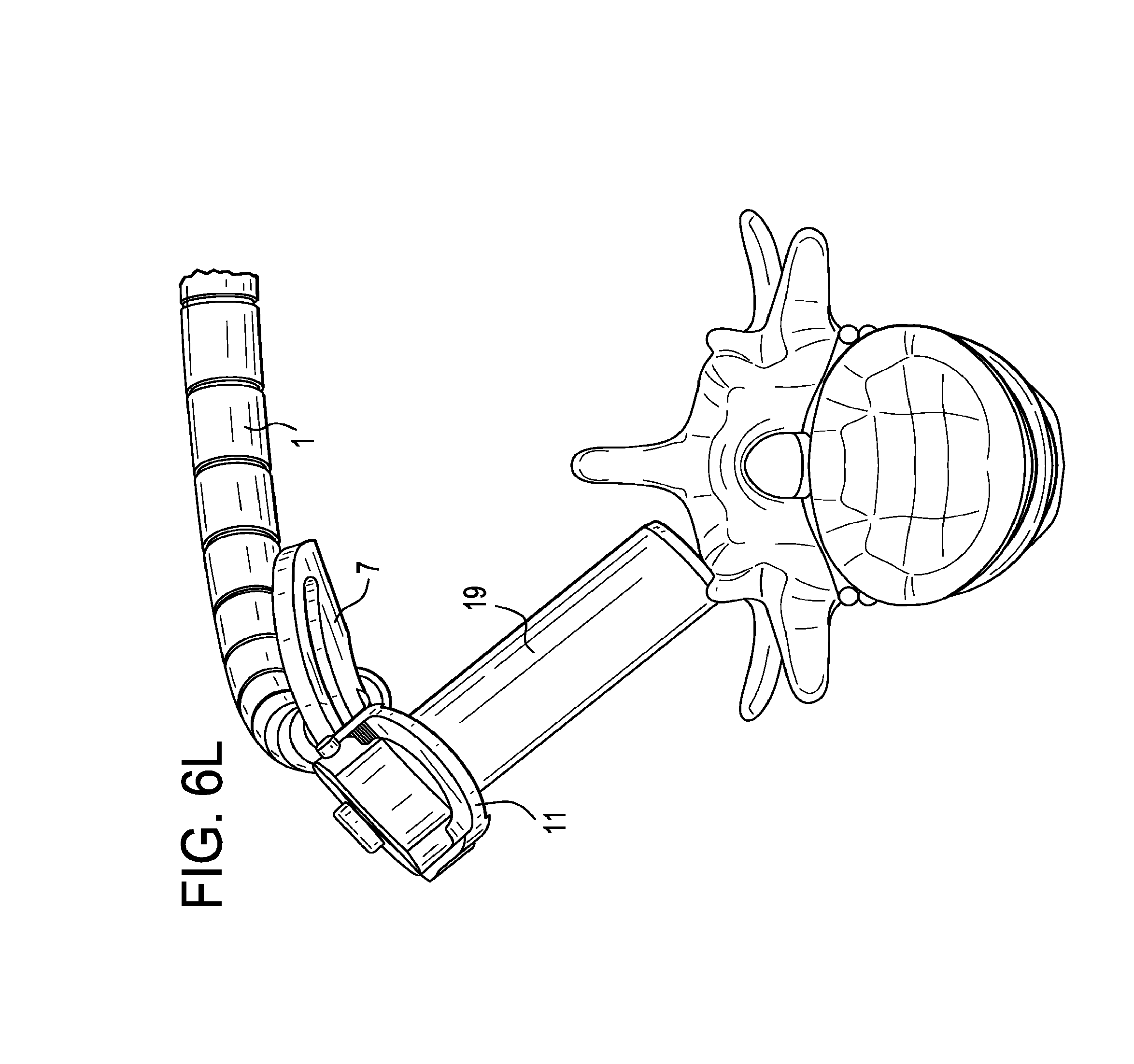
FIGS. 6C, 6K, 6L, 6M, 6N and 6O disclose various desirable orientations of the fourth apparatus embodiment relative to a functional spinal unit.
FIGS. 6D-6E disclose the possible cranial-caudal tilt angles of the fourth embodiment.
FIGS. 6F-6G disclose the possible medial-lateral tilt angles of the fourth embodiment.
FIGS. 6H-6J disclose respective side, perspective and top views of the fourth embodiment apparatus.
FIGS. 6K-6O disclose various views of the apparatus in relation to the spine.
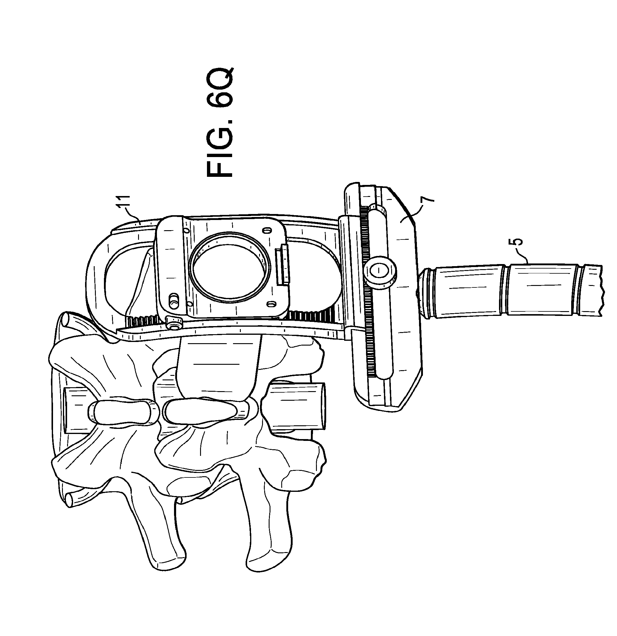
FIGS. 6P-6Q disclose views of the fourth embodiment apparatus wherein the medial-lateral bar runs parallel to the spine.
FIG. 7 discloses an apparatus for supporting a surgical instrument, such as an endoscope, in relation to a patient.
DETAILED DESCRIPTION OF THE INVENTION
For the purposes of the present invention, the "distal end portion of the tube" is the portion of the tube that is nearest to the patient and furthest from the surgeon when the tube is inserted into the patient, and the "proximal end portion of the tube" is the portion of the tube that is furthest from the patient and nearest to the surgeon when the tube is inserted into the patient. Also, "a working channel" and "a tube" are considered to be interchangeable. In some embodiments, a surgical instrument, or surgical visualization instrument, can be inserted through the tube, mounted to an interior or exterior of the tube, and/or movably or fixedly coupled to the tube. While tubes are described in many of the examples herein, the tube can be replaced with a surgical instrument, such as an endoscope or surgical visualization instrument.
In the following description, several concepts are described covering the subjects of a) limiting lateral motion of the proximal end portion of the tube, b) eliminating the lateral motion of the proximal end portion of the tube, and c) eliminating the axial motion of the proximal end portion of the tube.
Now referring to FIG. 2, there is provided a minimally-invasive surgical access system, comprising;
a) a tube 1 having an outer wall 3, a longitudinal bore 5, a proximal end portion 7 and a distal end portion 9;
b) a sliding tab 11 comprising a collar 13 having a pair of opposed flanges 15 extending therefrom, wherein the collar is slidable along the outer wall of the tube; and
c) an annular frame 17 having a pair of substantially opposed slots 19, wherein the flanges of the collar respectively extend through the slots of the annular frame, and wherein the tube extends through the annular frame.
The embodiment shown in FIG. 2 includes an annular frame that can be fixed onto a stationary unit, such as the operating table, so as to anchor the system. As previously described, the distal end portion of the tube can be fixed onto the bony structures (such as a vertebral body) or soft tissues (such as disc cartilage) within the lumbar spine. When the tube is so distally anchored, the proximal end portion of the tube can move in a substantially conical volume, with the distal end of the tube being its apex. The fixed-in-space annular frame of the embodiment of FIG. 2 limits the range of the motion of the proximal end portion of the tube. The sliding tab component of the system is comprised of a collar with a pair of opposed flanges extending therefrom. Preferably, the shape of the flanges describes a portion of a spherical surface that mimics the limited motion of the tube. The outer annular frame has a pair of opposed matching slots that slidably receive their respective flanges. Preferably, each slot is shaped as an arc that matches the arc-like transverse cross-section of the flange it receives. The working channel is mounted and fixed onto the sliding tab using a set screw 21 that is received in a threaded hole in the collar. The set screw can extend through the collar and contact the outer wall of the tube in the proximal end portion of the tube so as to lock the collar to the tube, thereby preventing the motion of the tube channel in the axial direction. The limits of the lateral motion of the proximal end portion are defined by the outer annular frame. The outer annular frame can be fixed onto the operating table 24 using an extension arm 23.
Therefore, in preferred embodiments of the first embodiment of the present invention, the system further comprises an arm extending from a stationary unit, wherein the arm is attached to the annular frame. Preferably, the collar comprises a threaded hole, and the system further comprises a set screw received in the threaded hole of the collar. Preferably, the set screw can extend through the collar and contact the outer wall of the tube in the proximal end portion of the tube to lock the collar to the tube. Preferably, each flange comprises a portion of a spherical surface 25 and each slot describes an arc, wherein the flange mates with the slot. Preferably, the distal end portion of the tube has a docking feature (such as a plurality of distally-extending teeth 27) adapted to dock to bone or cartilage. In some embodiments, the collar does not contact the annular frame. In some embodiments, the annular frame has a cutout 29 adapted to allow access by a screwdriver to the collar in order to tighten or loosen the set screw. Preferably, this cutout aligns radially with the set screw. Preferably, the proximal end portion of the tube is able to move in a substantially frustoconical volume when the distal end portion of the tube is fixed. The tube can be a surgical instrument, can be replaced with a surgical instrument, and/or can include a surgical instrument, e.g., inserted therethrough. The surgical instrument can be an endoscope or other visualization instrument. The system need not necessarily provide surgical access, but rather can be used solely for supporting an endoscope or other surgical instrument, or for doing this in combination with other functions.
Now referring to FIG. 3, there is provided a minimally-invasive surgical access system, comprising;
a) a tube 31 having an outer wall 33, a longitudinal bore 35, a proximal end portion 37, a distal end portion 39, and a substantially spherical element 41 radially surrounding a segment of the outer wall;
b) a sliding tab 43 having a base 45 and a pair of opposed flanges 47 extending therefrom; the base having a hole 48 therethrough defining a rim 49 having a static portion 51 and a slidable portion 53,
c) an annular frame 55 having a pair of substantially opposed slots 57, wherein each flange of the sliding tab extends through a respective slot of the annular frame, wherein the tube extends through the annular frame, and wherein the static portion of the rim releasably contacts a first portion of the substantially spherical element and the slidable portion of the rim releasably contacts a second portion of the substantially spherical element.
The second embodiment of FIG. 3 includes an outer annular frame that could be fixed onto a stationary unit, such as the operating table. As previously described, the distal end portion of the tube can be fixed onto the bony structures or soft tissues of the spine, so that the proximal end portion of the tube can move in a substantially frustoconical volume with the distal tip being the apex. In this particular embodiment, the sliding tab has flat flanges, which are easier to manufacture. Likewise, the outer annular frame has a pair of simple, linear slots to slidably receive the flanges. The sliding tab has an axial hole therein defining a rim, the rim comprising a static hemispherical portion, as well as a movable hemispherical portion. As the working channel passes into the sliding-tab, the set screw 61 can be turned to move the dynamic hemisphere to hold or release the spherical protrusion of the working channel, thereby fixing or release the angel of the sliding tab with respect to the tube. This allows for the movement on the desired range. The whole structure allows for sideways motion of the distal end in a given range (defined by the slot on the outer frame) and blocks the axial motion of the distal end.
Preferably, in this second embodiment, the system further comprises an arm 63 extending from a stationary unit 64, wherein the arm is attached to the annular frame. Preferably, the base comprises a first cutout 65, and further comprises a sliding door 66 slidably received in the cutout. Preferably, the sliding door comprises the second portion of the rim. Preferably, the sliding door further comprises a substantially hemispherical portion extending from the slidable portion of the rim, wherein the substantially hemispherical portion releasably contacts the second portion of the substantially spherical element to lock the sliding tab to the tube. Preferably, the sliding door is slidably actuated by a set screw. Preferably, each flange of the sliding tab is flat and each respective slot is substantially rectangular, so that the flange mates with the slot. Preferably, the distal end portion of the tube has a docking feature (such as distally extending teeth 67) adapted to dock to bone or cartilage. In some embodiments, the substantially spherical element does not contact the annular frame. Preferably, the annular frame has a second cutout 69 (designed to allow access by a screwdriver) that aligns radially with the set screw. Preferably, the proximal end portion of the tube is able to move in a substantially frustoconical volume when the distal end portion of the tube is fixed. In some embodiments, the flat flanges of the sliding tab are not orthogonal to the tube. The tube can be a surgical instrument, can be replaced with a surgical instrument, and/or can include a surgical instrument, e.g., inserted therethrough. The surgical instrument can be an endoscope or other visualization instrument. The system need not necessarily provide surgical access, but rather can be used solely for supporting an endoscope or other surgical instrument, or for doing this in combination with other functions.
Now referring to FIGS. 4A-4B, there is provided a minimally invasive surgical access system, comprising;
a) an upper cap 71 describing a first portion 73 of a substantially spherical surface,
b) an middle cap 75 describing a second portion 77 of the substantially spherical surface and having a central hole 79,
c) a lower cap 81 describing a third portion 83 of the substantially spherical surface,
d) a tube 85 having an outer wall 87 having an attachment portion 89, a longitudinal bore 91, a proximal end portion 93, a distal end portion 95, wherein the upper cap and the lower cap are attached to and radially extend from the outer wall of the tube, wherein at least one of the upper cap and the lower cap is removably attached to the outer wall of the tube, wherein the tube is received in the central hole of the middle cap, and wherein the middle cap is received between the upper cap and the lower cap.
This concept comprises three spherical caps on top of each other. The middle cap is the proximal point where the rigid arm is fixed. The lower cap extends from the working channel and is preferably integral with the working channel. This lower cap helps to prevent the working channel from being pulled proximally through the hole of the middle cap. The middle cap has a hole of predetermined size that allows for limited lateral motion of the working channel, thereby defining the boundaries of allowed motion. The middle cap is fixed to the operating table via attachments as described above. This middle cap may have a fixation element to help with the fixation. The upper cap has a threaded hole 97 and, when threaded onto the threaded 89 portion of the working channel, helps preventing the channel from advancing distally. In this concept, if the upper cap is advanced distally, it will create friction between the caps and will prevent the motion of the caps relative to each other. In other words, this concept allows for the motion of the working channel and at the same time allows for complete fixation of the distal and proximal ends of the working channel at desired direction.
Preferably, in the embodiment of FIG. 4, the upper cap is located proximal to the lower cap. Preferably, the middle cap has a fixation element 101 for fixation to a stationary unit. Preferably, the system further comprises an arm 103 extending from a stationary unit 105, wherein the arm is attached to the fixation element. Preferably, the proximal portion of the tube is able to move in a substantially frustoconical volume when the distal end portion of the tube is fixed. Preferably, the distal end portion of the tube has a docking feature 107 adapted to dock to bone. Preferably, the upper cap, middle cap, and lower cap are located in a proximal-most quarter PQ of the tube.
In some embodiments, the upper cap has a threaded hole 97, the outer wall of the working channel has a threaded portion 89, and wherein the upper cap is threadably received on the threaded portion of the outer wall of the tube.
In FIG. 4, the upper cap is shown to be removable by virtue of its threadability upon the outer wall of the tube. However, removability is not restricted to threaded features. For example, in some embodiments, the tube and cap may provide a Morse taper lock. In other embodiments, the cap is made of an elastic material that snugly fits the outer wall of the tube.
In some embodiments, one of the upper cap and the lower cap is removably attached to the outer wall of the tube, and the other is integrally attached to the outer wall of the tube.
In some embodiments, one of the upper or lower cap has a threaded hole, the outer wall has a threaded portion, and the cap having the threaded hole is threadably received on the threaded portion of the outer wall of the tube.
In some embodiments, both of the upper cap and the lower cap are removably attached to the outer wall of the tube, preferably threadably attached.
A functional prototype of this method is shown in FIGS. 5A-C, with different steps of mounting and securing. In FIG. 5A, a tube having an upper threaded portion and a lower cap permanently attached thereto is provided. In FIG. 5B, the middle cap is lowered onto the lower cap. In FIG. 5C, an upper cap with a threaded hole is placed over the middle cap and threaded onto the threaded portion of the tube, thereby trapping the middle cap between the upper and lower caps. Lastly, the middle cap is affixed to a stationary unit.
In some embodiments, the features of the upper and lower caps are reversed. Therefore, in accordance with the present invention, one of the upper cap and the lower cap is removably attached to the outer wall of the tube, and the other of the caps is integrally attached to the outer wall of the tube. Alternatively, both of the upper cap and the lower cap are removably attached to the outer wall of the tube.
The tube can be a surgical instrument, can be replaced with a surgical instrument, and/or can include a surgical instrument, e.g., inserted therethrough. The surgical instrument can be an endoscope or other visualization instrument. The system need not necessarily provide surgical access, but rather can be used solely for supporting an endoscope or other surgical instrument, or for doing this in combination with other functions.
It is believed that the above-described embodiments are generally suitable for use in typical percutaneous spinal surgeries, in conjunction with working channel diameters of only a few millimeters. However, there are certain spinal surgeries in which use of the above embodiments could require very large and bulky constructs. These certain surgeries (which include direct decompression surgeries performed through a mini-open posterior or para-medial approach) often require:
a) the tube of the working channel diameter to be larger-than-usual (e.g., from about 10 mm to about 30 mm in diameter), or
b) larger cranial-caudal and medial-lateral tilt angles, so that a larger angular range of motion is realized.
Therefore, in an effort to address these situations, in a fourth embodiment, and now referring to FIGS. 6A-6O, there is provided an apparatus comprising:
a) an arm 1 having a proximal end portion 3 connected to a stationary object and a distal end portion 5,
b) a medial-lateral bar 7 connected to the distal end portion of the arm and having a first rail 9;
c) a cranial-caudal bar 11 having:
i) a first rail 13 in slidable engagement with the first rail of the medial-lateral bar in a first direction and
ii) a second rail 15 extending substantially perpendicularly from the first rail of the cranial-caudal bar;
d) a working channel construct 17 comprising:
i) a tube 19 having an outer surface 20 and a proximal end portion 22, and
ii) a slider 21 attached to the outer surface of the tube and having a first rail 23 in slidable engagement with the second rail of the cranial-caudal bar.
This fourth embodiment functions substantially similarly to the previously-described embodiments. For example, its working channel tube has a restricted range of motion in the axial direction. Secondly, the fourth embodiment also allows for angular movement of the proximal end of the working channel construct, so as to always leave the tube's tip in the same position. See, for example, FIGS. 6D-6G.
This fourth embodiment is especially suitable in direct decompression surgeries when a) the tube of the working channel diameter needs to be from about 10 mm to about 30 mm in diameter, or b) larger cranial-caudal and medial-lateral tilt angles are needed, so that a larger angular range of motion is needed.
In FIG. 6A-6B of the present invention, during the surgery, the working channel tube may be attached to and detached from a slider. Various coupling or push-button mechanisms can be selected for this attachment.
In FIGS. 6A-6O, the slider is slidably connected to the cranial-caudal bar by mating rails. Preferably, the mating rails of the slider and cranial-caudal bar have mating arcuate shapes. See FIGS. 6D-6E. Preferably, the curvature of these arcuate rails is selected so that the common radius defined by their curves corresponds to the distance between the curve location and the tip of the working channel tube in the final assembly. In other words, the distal tip of the working channel tube defines the centerpoint of the circle described by the mating rails. In this way, it is insured that when the position of the slider along the rail of the cranial-caudal bar is changed in space, the location in space of the centerpoint tube distal end does not change, only the direction of the working channel tube central axis changes. Typically, the curved slider rail can smoothly glide along its mating curved rail of the cranial-caudal bar (thereby continuously changing the cranial-caudal angle of the working channel construct). However, in some embodiments, the relative positions of these rails against each other can be fixed. Various mechanisms can be selected to fix a relative position of these rails. For example, opposing teeth can be provided along each of the mating rails, as in FIG. 6A. These teeth can act as anchors when a fixation is desired. This fixation defines the cranial-caudal angle of the working channel tube.
In FIGS. 6A-6O, the first and second rails of the cranial-caudal bar are each arcuate. Preferably, the arcs of these rails are equal, so that the cranial-caudal bar defines a spherical surface. The center of the sphere is defined by the tip location of the working channel construct in the final assembly. The rail of the medial-lateral bar mates with the first rail of the cranial-caudal bar and so also preferably has an arcuate shape of the same radius. The two bar components are slidably connected to each other by these arcuate rails. A bolt-slot connection or similar construct can be used to slidably connect the two bars in order to assure that the cranial-caudal bar not only keeps its perpendicular orientation relative to the medial-lateral bar, but is also able to slide along the slot. The position of the cranial-caudal bar relative to the medial-lateral bar defines the medial-lateral angle of the working channel construct. The position can be fixed if desired. Various mechanisms can be considered to realize the position of fixation. For example, teeth can be provided along each rail that act as anchors.
In FIG. 6C, the medial-lateral bar is attached to a rigid arm, whose position can be fixed relative to the operating room table during the surgery.
Although the cranial-caudal bar is shown in FIG. 6A as having four rails forming a rectangle with an internal window, in some embodiments, the cranial-caudal bar could potentially consist of 3 rails (defining a "U"-Shape) or 2 rails (defining an "L-"shape). Although the described "4-rail" configuration likely provides for the highest stability of these embodiments against bending of the working channel construct around the axis along the bar, and can provide for the finest dimensions of the rails at the same time, an very stiff sliding/connection mechanism that only needs support from one rail, or without the stabilization of the closing-rod, can also be considered as well.
In some embodiments (as in FIG. 6B), the cranial-caudal bar has a release button 25 for releasable attachment to the medial-lateral bar. Typically, pressing this button releases the engagement of a teeth-like element on the cranial-caudal bar within the tee engages the teeth of the rail of the medial-lateral bar.
In some embodiments (as in FIG. 6B), the slider has a release button 27 for releasable attachment to the cranial-caudal bar. Typically, this button engages the teeth of the second rail of the cranial-caudal bar.
In some embodiments (as in FIG. 6A), the medial-lateral bar has a first window 29 or slot therein for slidable reception of the cranial-caudal bar. Typically, the slot is adjacent the rail of the medial-lateral bar, and the first rail of the cranial-caudal bar has a bolt-like shape so as to provide a slidable bolt-slot connection with the medial-lateral bar.
In some embodiments (as in FIG. 6A), the cranial-caudal bar has a third rail 31 extending from the first rail of the cranial-caudal bar in a direction substantially parallel to the second rail of the cranial-caudal bar. This embodiment can provide a cranial-caudal bar having a U-shape. In this embodiment, stops can be provided at the two ends of the U-shape so that the slider remains within the pocket of the U-shape.
In some embodiments, the slider further comprises iii) a second rail (not shown) substantially parallel to the first rail of the slider, wherein the second rail of the slider is in slidable engagement with the third rail of the cranial-caudal bar.
In some embodiments (as in FIG. 6B), the tube is disposed between the second and third rails of the cranial-caudal bar. This allows the forces that act upon the tube to be evenly supported by the pair of rails of the cranial-caudal bar.
In some embodiments (as in FIG. 6A), a fourth rail (connecting bar) 35 connects the second and third rails of the cranial-caudal bar to form a second window 37, and the tube extends through the second window. This ensures that the slider will remain slidably attached to the cranial-caudal bar.
In some embodiments (as in FIG. 6B), the first rail of the medial-lateral bar and the first rail of the cranial-caudal bar have mating teeth 39 thereon, and the second rail of the cranial-caudal bar and the first rail of the working channel construct have mating teeth 41 thereon. With the help of a member that is integrated to the component that is sliding along the rail with the teeth, and that can engage the teeth, this allows the relative positions of the components to be fixed, thereby insuring the location of the working channel tube relative to the patient.
In some embodiments, a medical device is located within the tube. In some embodiments, thereof, the medical device is an instrument, while in others the medical device is an implant. Typically, the medical device is passed from the proximal end portion of the tube to the distal end portion of the working tube.
In some embodiments, the first rail of the medial-lateral bar and the first rail of the cranial-caudal bar have matching arcuate shapes. This allows the tube to be tilted with respect to the patient in a first plane while maintaining the location of the distal end of the tube.
In some embodiments, the second rail of the cranial-caudal bar and the first rail of the slider have matching arcuate shapes. This allows the tube to be tilted with respect to the patient in a second plane while maintaining the location of the distal end of the tube.
In some embodiments, the slider is attachable and detachable from/to the outer surface of the tube at the proximal end portion of the tube. This allows a fine control of the location of the proximal end portion of the tube. This allows as well that the tube can be introduced into the patient at the right location in a first step of a surgery. The rest of the components are pre-assembled and can be attached to the tube at this attachment location of the slider, while the arm is in a flexible configuration. After attaching the tube to the rest of the assembly, the arm can be brought to a rigid configuration, leaving only the option of changing the position of the tube, with respect to the patient to the angular changes by the rail connections.
In some embodiments, the first rail of the cranial-caudal is in slidable engagement with the first rail of the medial-lateral bar by virtue of a bolt-slot connection. This arrangement helps maintain the orientation of the cranial-caudal bar vis-a-vis the medial-lateral bar. FIGS. 6K-6L disclose views of the fourth embodiment apparatus wherein the medial-lateral bar runs parallel to the spine.
The tube can be a surgical instrument, can be replaced with a surgical instrument, and/or can include a surgical instrument, e.g., inserted therethrough. The surgical instrument can be an endoscope or other visualization instrument. The system need not necessarily provide surgical access, but rather can be used solely for supporting an endoscope or other surgical instrument, or for doing this in combination with other functions.
For example, FIG. 7 illustrates an exemplary embodiment in which the tube is replaced with an endoscope 59. The endoscope can be flexible or rigid. The endoscope can include any one or more of a lens, a light source, a camera, an eyepiece, and a working channel. The endoscope can be cystoscope, nephroscope, bronchoscope, arthroscope, colonoscope, and/or laparoscope. The endoscope can be used to visualize a surgical site within a patient's body, such as the spine, abdomen, pelvis, joints, GI system, colon, bladder, kidney, throat, ear, cranium, or the like.
The components of the present invention are preferably made from a biocompatible metal such as stainless steel, titanium alloy or cobalt-chrome. However, it is contemplated that the components can be made from polymeric materials so as to provide an inexpensive, single use system.
* * * * *
D00000
D00001
D00002
D00003
D00004
D00005
D00006
D00007
D00008
D00009
D00010
D00011
D00012

D00013

D00014

D00015

D00016
D00017

D00018

D00019

D00020
D00021

XML
uspto.report is an independent third-party trademark research tool that is not affiliated, endorsed, or sponsored by the United States Patent and Trademark Office (USPTO) or any other governmental organization. The information provided by uspto.report is based on publicly available data at the time of writing and is intended for informational purposes only.
While we strive to provide accurate and up-to-date information, we do not guarantee the accuracy, completeness, reliability, or suitability of the information displayed on this site. The use of this site is at your own risk. Any reliance you place on such information is therefore strictly at your own risk.
All official trademark data, including owner information, should be verified by visiting the official USPTO website at www.uspto.gov. This site is not intended to replace professional legal advice and should not be used as a substitute for consulting with a legal professional who is knowledgeable about trademark law.