Zoom lens having a high zoom ratio and high performance over an entire zoom range and image pickup apparatus including the same
Sanjo
U.S. patent number 10,261,293 [Application Number 14/695,536] was granted by the patent office on 2019-04-16 for zoom lens having a high zoom ratio and high performance over an entire zoom range and image pickup apparatus including the same. This patent grant is currently assigned to CANON KABUSHIKI KAISHA. The grantee listed for this patent is CANON KABUSHIKI KAISHA. Invention is credited to Yotaro Sanjo.
View All Diagrams
| United States Patent | 10,261,293 |
| Sanjo | April 16, 2019 |
Zoom lens having a high zoom ratio and high performance over an entire zoom range and image pickup apparatus including the same
Abstract
Provided is a zoom lens, including, in order from an object side to an image side: a first lens unit having a positive refractive power that does not move for zooming; a second lens unit having a negative refractive power that moves during zooming; at least one lens unit that moves during zooming; and a rear lens unit including an aperture stop, in which a focal length of the zoom lens at a wide angle end, a focal length of the first lens unit, a focal length of the second lens unit, and a half angle of field of the zoom lens at the wide angle end are appropriately set.
| Inventors: | Sanjo; Yotaro (Utsunomiya, JP) | ||||||||||
|---|---|---|---|---|---|---|---|---|---|---|---|
| Applicant: |
|
||||||||||
| Assignee: | CANON KABUSHIKI KAISHA (Tokyo,
JP) |
||||||||||
| Family ID: | 54355147 | ||||||||||
| Appl. No.: | 14/695,536 | ||||||||||
| Filed: | April 24, 2015 |
Prior Publication Data
| Document Identifier | Publication Date | |
|---|---|---|
| US 20150316756 A1 | Nov 5, 2015 | |
Foreign Application Priority Data
| May 1, 2014 [JP] | 2014-094611 | |||
| Current U.S. Class: | 1/1 |
| Current CPC Class: | G02B 27/0025 (20130101); G02B 15/173 (20130101); G02B 15/20 (20130101) |
| Current International Class: | G02B 27/00 (20060101); G02B 15/173 (20060101); G02B 15/20 (20060101) |
| Field of Search: | ;359/689,691,687,688,690,692,793,794,795,796 |
References Cited [Referenced By]
U.S. Patent Documents
| 2009/0040625 | February 2009 | Shinohara |
| 2011/0255176 | October 2011 | Shinohara |
| 2012/0057251 | March 2012 | Takato |
| 2014/0118841 | May 2014 | Toyama |
| H07-325252 | Dec 1995 | JP | |||
| H10-161026 | Jun 1998 | JP | |||
| H11-160620 | Jun 1999 | JP | |||
| 2011-81065 | Apr 2011 | JP | |||
| 2011-175185 | Sep 2011 | JP | |||
| 2012-150248 | Aug 2012 | JP | |||
Other References
|
Japanese office action issued in corresponding application No. 2014094611 dated Jan. 11, 2018, with translation, 9 pages. cited by applicant. |
Primary Examiner: Alexander; William R
Assistant Examiner: Duong; Henry A
Attorney, Agent or Firm: Carter, DeLuca & Farrell, LLP
Claims
What is claimed is:
1. A zoom lens comprising in order from an object side to an image side: a first lens unit having a positive refractive power and configured not to move for zooming; a second lens unit having a negative refractive power and configured to move for zooming; at least one lens unit configured to move for zooming; and a rear lens unit including an aperture stop, wherein an interval of each pair of adjacent lens units of the first lens unit, the second lens unit, the at least one lens unit and the rear lens unit is changed for zooming, and wherein the zoom lens satisfies expressions -12.00<f1/f2<-4.00; -0.99<f2/(2.times.fW.times.tan(.omega._W))<-0.30; and -0.05<f2/L2W<-0.05, where fW represents a focal length of the zoom lens at a wide angle end, f1 represents a focal length of the first lens unit, f2 represents a focal length of the second lens unit, .omega._W represents a half angle of field of the zoom lens al the wide angle end, and L2W represents an interval on an optical axis between a surface, closest to the image side, of the second lens unit and a surface, closest to the object side, of the at least one lens unit at the wide angle end.
2. A zoom lens according to claim 1, wherein the zoom lens satisfies an expression 9.00<.beta.2T/.beta.2W<35.00, where .beta.2W represents a lateral magnification of the second lens unit at the wide angle end and at infinity in an object distance, and .beta.2T represents a lateral magnification of the second lens unit at a telephoto end and at infinity in the object distance.
3. A zoom lens according to claim 1, wherein the zoom lens satisfies an expression 4.00<LF/(2.times.fW.times.tan(.omega._W))<20.00, where LF represents a distance on an optical axis from a surface, closest to the object side, of the first lens unit to the aperture stop.
4. A zoom lens according to claim 1, wherein the zoom lens satisfies an expression 10.00<fT/(2.times.fW.times.tan(.omega._W))<40.00, where fT represents a focal length of the zoom lens at a telephoto end.
5. A zoom lens according to claim 1, wherein the aperture stop does not move for zooming.
6. An image pickup apparatus, comprising: a zoom lens comprising, in order from an object side to an image side: a first lens unit having a positive refractive power and configured not to move for zooming; a second lens unit having a negative refractive power and configured to move for zooming; at least one lens unit configured to move for zooming; and a rear lens unit including an aperture stop, wherein an interval of each pair of adjacent lens units of the first lens unit, the second lens unit, the at least one lens unit and the rear lens unit is changed for zooming, and wherein the zoom lens satisfies expressions -12.00<f1/f2<-4.00; -0.99<f2/(2.times.fW.times.tan(.omega._W))<-0.30; and -0.50<f2/L2W<-0.05, where fW represents a focal length of the zoom lens at a wide angle end, f1 represents a focal length of the first lens unit, f2 represents a focal length of the second lens unit, .omega._W represents a half angle of field of the zoom lens at the wide angle end, and L2W represents an interval on an optical axis between a surface, closest to the image side, of the second lens unit and a surface, closest to the object side, of the at least one lens unit at the wide angle end; and an image pickup element configured to receive an image formed by the zoom lens.
7. A zoom lens according to claim 1, wherein the zoom lens performs focusing with a lens unit which is disposed on an object side of the aperture stop.
8. A zoom lens according to claim 1, wherein the zoom lens satisfies an expression 2.00<fT/f1<8.00, where fT represents a focal length of the zoom lens at a telephoto end.
9. A zoom lens according to claim 1, wherein the zoom lens satisfies an expression 2.39.ltoreq.fT/f1<8.00, where fT represents a focal length of the zoom lens at a telephoto end.
10. A zoom lens according to claim 1, wherein the zoom lens satisfies an expression 3.59.ltoreq.fT/f1<8.00, where fT represents a focal length of the zoom lens at a telephoto end.
11. A zoom lens according to claim 1, wherein the zoom lens satisfies an expression -12.00<f1/f2<-5.00.
12. A zoom lens comprising in order from an object side to an image side: a first lens unit having a positive refractive power and configured not to move for zooming; a second lens unit having a negative refractive power and configured to move for zooming; at least one lens unit configured to move for zooming; and a rear lens unit including an aperture stop, wherein an interval of each pair of adjacent lens units of the first lens unit, the second lens unit, the at least one lens unit and the rear lens unit is changed for zooming, and wherein the zoom lens satisfies expressions -12.00<f1/f2<-5.00; -1.00<f2/(2.times.fW.times.tan(.omega._W))<-0.30; and -0.50<f2/L2W<-0,05, where fW represents a focal length of the zoom lens at a wide angle end, f1 represents a focal length of the first lens unit, f2 represents a focal length of the second lens unit, .omega._W represents a half angle of field of the zoom lens at the wide angle end, and L2W represents an interval on art optical axis between a surface, closest to the image side, of the second lens unit and a surface, closest to the object side, of the at least one lens unit at the wide angle end.
13. A zoom lens according to claim 12, wherein the zoom lens satisfies an expression 9.00<.beta.2T/.beta.2W<35.00, where .beta.2W represents a lateral magnification of the second lens unit at the wide angle end and at infinity in an object distance, and .beta.2T represents a lateral magnification of the second lens unit at a telephoto end and at infinity in the object distance.
14. A zoom lens according to claim 12, wherein the zoom lens satisfies an expression 4.00<LF/(2.times.fW.times.tan(.omega._W))<20.00, where LF represents a distance on an optical axis from a surface, closest to the object side, of the first lens unit to the aperture stop.
15. A zoom lens according to claim 12, wherein the zoom lens satisfies an expression 10.00<fT/(2.times.fW.times.tan(.omega._W))<40.00 where fT represents a focal length of the zoom lens at a telephoto end.
16. A zoom lens according to claim 12, wherein the aperture stop does not move for zooming.
17. An image pickup apparatus comprising: a zoom lens defined in claim 12; and an image pickup element configured to receive an image formed by the zoom lens.
18. A zoom lens according to claim 12, wherein the zoom lens performs focusing with a lens unit which is disposed on art object side of the aperture stop.
19. A zoom lens according to claim 12, wherein the zoom lens satisfies an expression 2.00<fT/f1<8.00, where fT represents a focal length of the zoom lens at a telephoto end.
Description
BACKGROUND OF THE INVENTION
Field of the Invention
The present invention relates to a zoom lens and an image pickup apparatus including the zoom lens, which are particularly suitable for use in a broadcasting television camera, a cinema camera, a video camera, a digital still camera, and a silver-halide film camera.
Description of the Related Art
In recent years, as an image pickup apparatus such as a television camera, a cinema camera, a video camera, or a film camera, a large format camera having features of a shallow depth of field and beautiful bokeh (blur) quality for expanding visual expression is used. As a zoom lens to be attached to the large format camera, a small and lightweight zoom lens having a high zoom ratio and high optical performance for securing mobility and improving flexibility in photography has been in demand. As the zoom lens having the high zoom ratio, as proposed in Japanese Patent Application Laid-Open Nos. 2011-175185 and 2012-150248, there has been known a positive-lead type zoom lens in which a lens unit having a positive refractive power is arranged closest to an object side and which includes four or more lens units in total.
In general, when an image size of the image pickup apparatus becomes large, the zoom lens to be attached thereto is accordingly increased in size. Therefore, in a case of being attached to the image pickup apparatus having the large image size, reductions in size and weight of the zoom lens become a problem.
The positive-lead type zoom lens described above is relatively easy to achieve the high zoom ratio. However, in order to realize an even higher zoom ratio, a moving amount of a second lens unit accompanying zooming is increased, which makes it difficult to achieve both the high zoom ratio and the reductions in size and weight. In order to realize the high zoom ratio and the reductions in size and weight with the above-mentioned positive-lead type zoom lens, it is particularly important to appropriately set refractive powers of a first lens unit and the second lens unit.
SUMMARY OF THE INVENTION
It is an object of the present invention to provide, as the above-mentioned positive-lead type zoom lens, a zoom lens which realizes a high zoom ratio and reductions in size and weight, and has high performance over an entire zoom range. More specifically, it is an object of the present invention to provide a zoom lens having an angle of field of about 46.8 to 56.8 degrees at a wide angle end, an angle of field of about 1.6 to 4.5 degrees at a telephoto end, and a magnification of about 11.times. to 30.times..
According to one embodiment of the present invention, there is provided a zoom lens, including, in order from an object side to an image side: a first lens unit having a positive refractive power that does not move for zooming; a second lens unit having a negative refractive power that moves during zooming; at least one lens unit that moves during zooming; and a rear lens unit including an aperture stop, the zoom lens satisfying the following expressions: -12.00<f1/f2<-4.00; and -1.00<f2/(2.times.fW.times.tan(.omega._W))<-0.30, where fW represents a focal length of the zoom lens at a wide angle end, f1 represents a focal length of the first lens unit, f2 represents a focal length of the second lens unit, and .omega._W represents a half angle of field of the zoom lens at the wide angle end.
According to the one embodiment of the present invention, as a zoom lens for a large format camera, in particular, there may be obtained the zoom lens which realizes the high zoom ratio and the reductions in size and weight, and has high optical performance over the entire zoom range from the wide angle end to the telephoto end, and an image pickup apparatus including the zoom lens.
Further features of the present invention will become apparent from the following description of exemplary embodiments with reference to the attached drawings.
BRIEF DESCRIPTION OF THE DRAWINGS
FIG. 1 is a lens cross-sectional view when focus is at infinity at a wide angle end in a zoom lens according to Embodiment 1 of the present invention.
FIG. 2A is a longitudinal aberration diagram when the focus is at infinity at the wide angle end in Embodiment 1.
FIG. 2B is a longitudinal aberration diagram when the focus is at infinity at a focal length of 180.00 mm in Embodiment 1.
FIG. 2C is a longitudinal aberration diagram when the focus is at infinity at a telephoto end in Embodiment 1.
FIG. 3 is a lens cross-sectional view when focus is at infinity at a wide angle end in a zoom lens according to Embodiment 2 of the present invention.
FIG. 4A is a longitudinal aberration diagram when the focus is at infinity at the wide angle end in Embodiment 2.
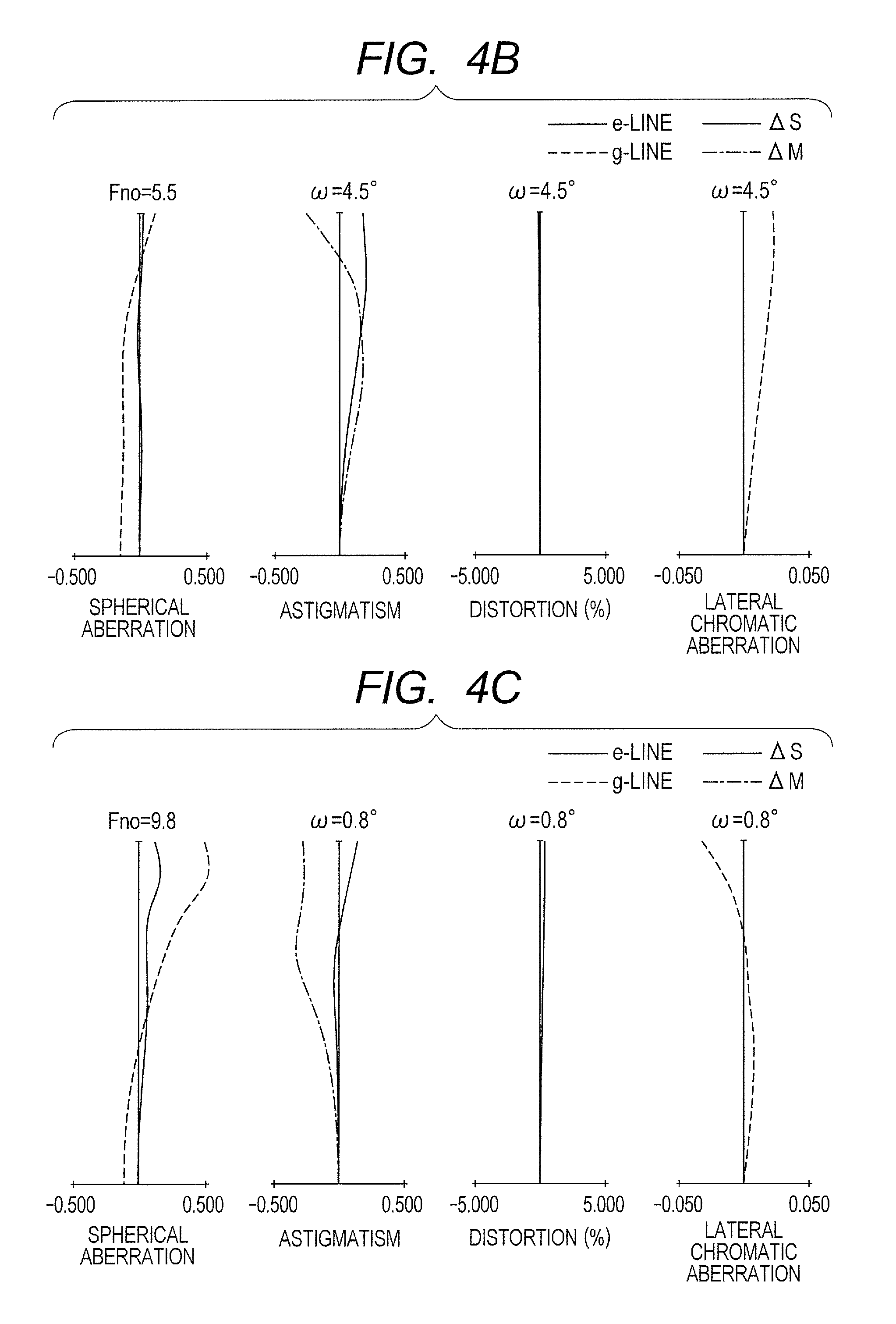
FIG. 4B is a longitudinal aberration diagram when the focus is at infinity at a focal length of 274.00 mm in Embodiment 2.
FIG. 4C is a longitudinal aberration diagram when the focus is at infinity at a telephoto end in Embodiment 2.
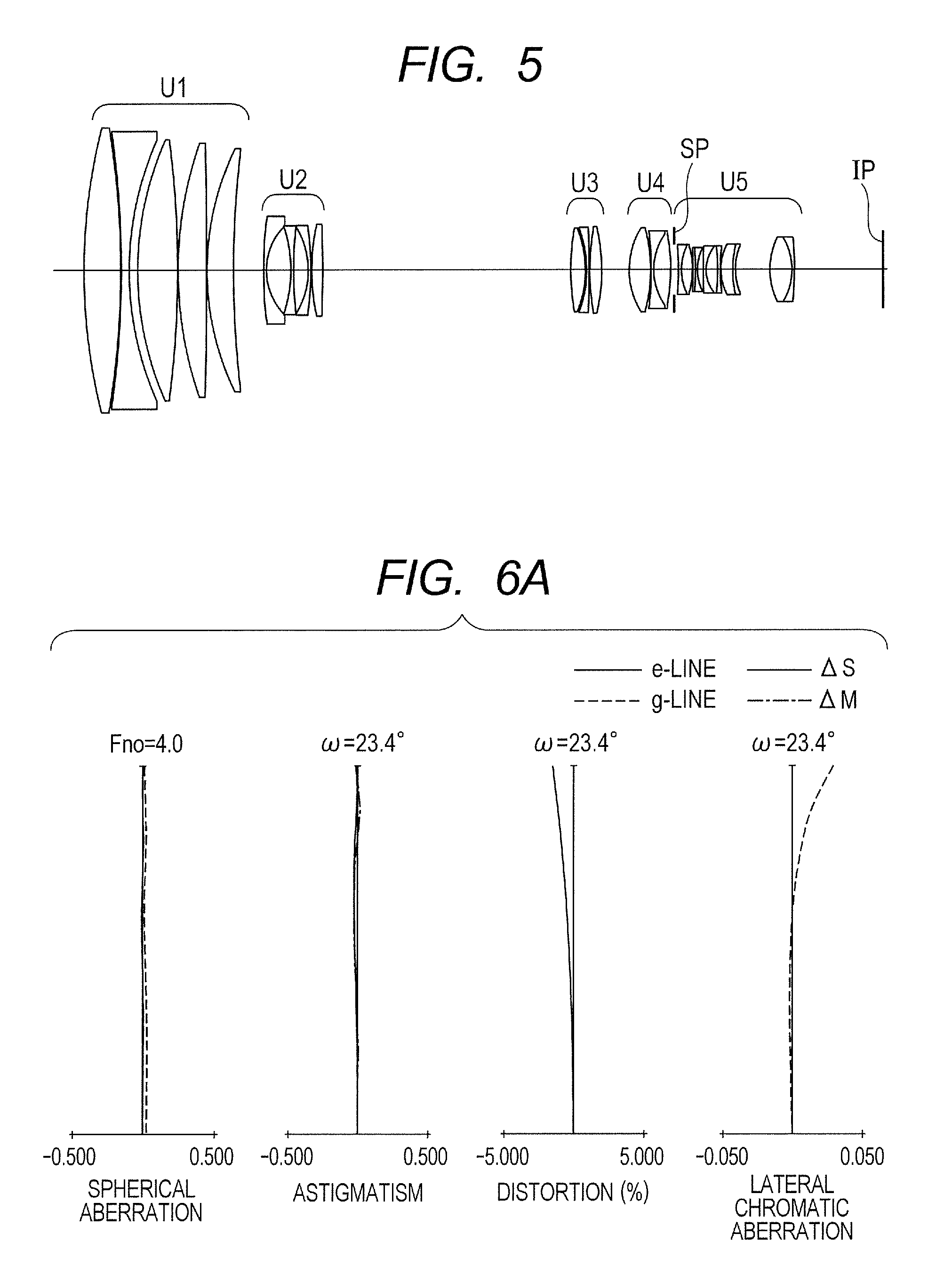
FIG. 5 is a lens cross-sectional view when focus is at infinity at a wide angle end in a zoom lens according to Embodiment 3 of the present invention.
FIG. 6A is a longitudinal aberration diagram when the focus is at infinity at the wide angle end in Embodiment 3.
FIG. 6B is a longitudinal aberration diagram when the focus is at infinity at a focal length of 166.00 mm in Embodiment 3.
FIG. 6C is a longitudinal aberration diagram when the focus is at infinity at a telephoto end in Embodiment 3.
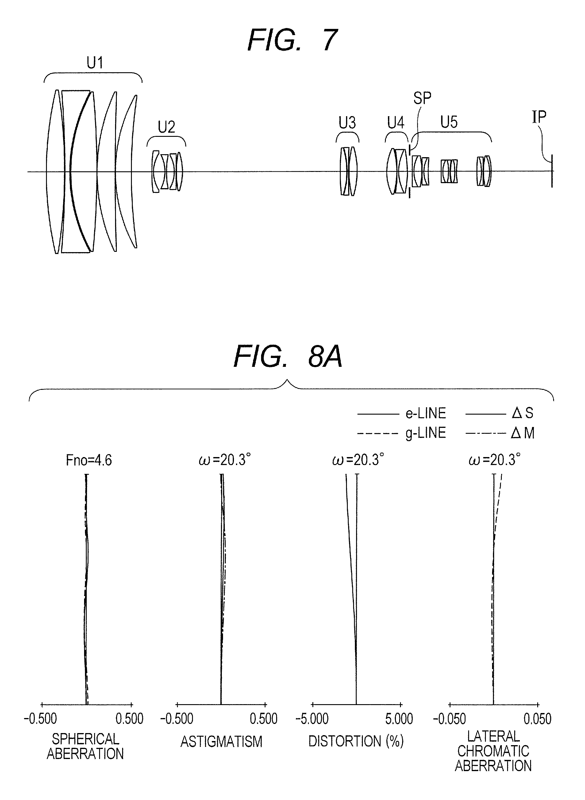
FIG. 7 is a lens cross-sectional view when focus is at infinity at a wide angle end in a zoom lens according to Embodiment 4 of the present invention.
FIG. 8A is a longitudinal aberration diagram when the focus is at infinity at the wide angle end in Embodiment 4.
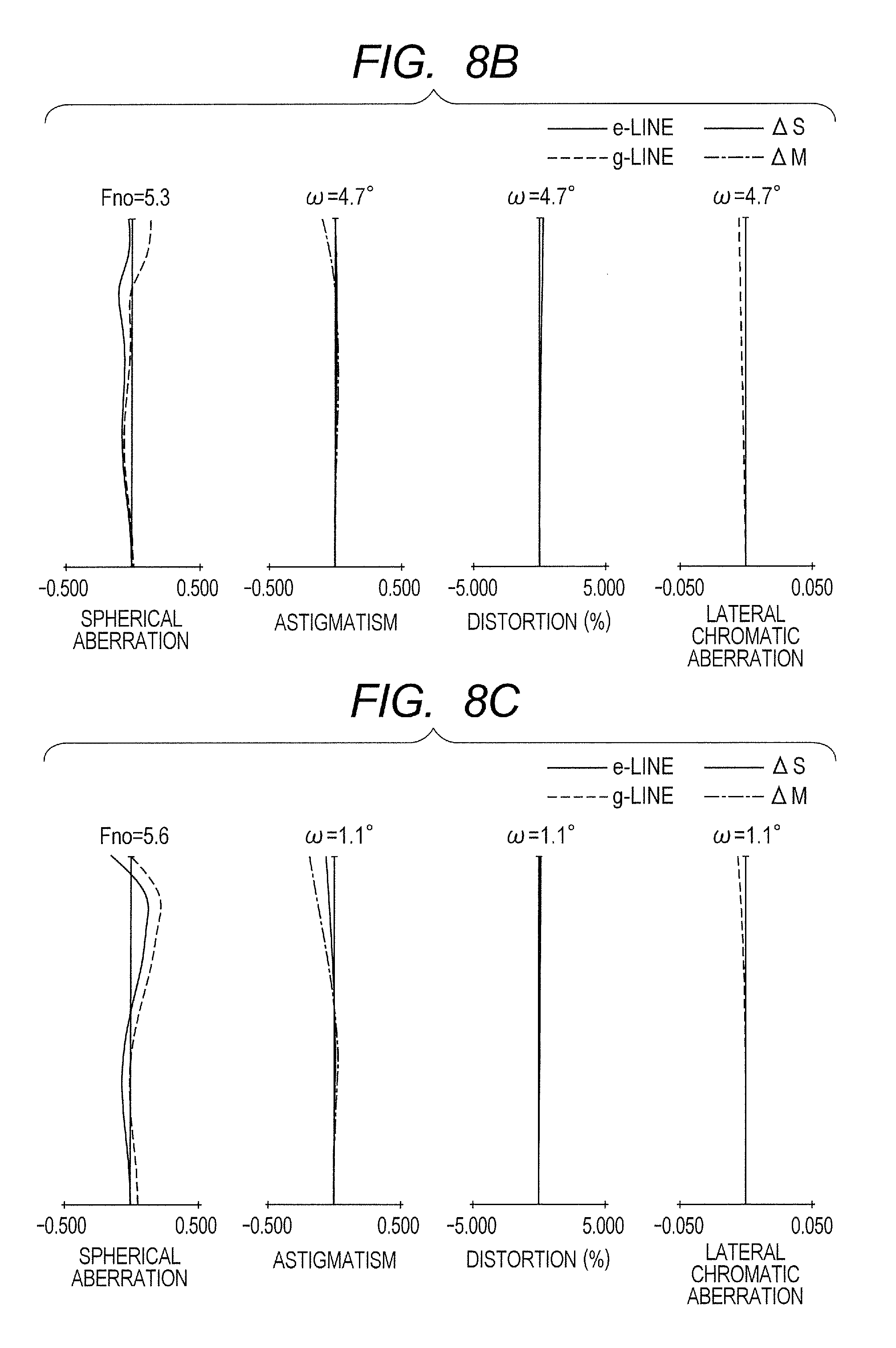
FIG. 8B is a longitudinal aberration diagram when the focus is at infinity at a focal length of 180.00 mm in Embodiment 4.
FIG. 8C is a longitudinal aberration diagram when the focus is at infinity at a telephoto end in Embodiment 4.
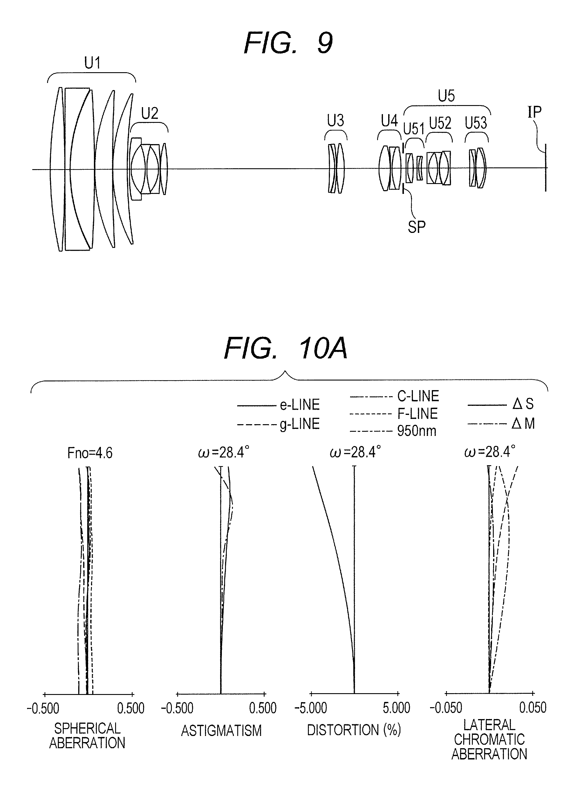
FIG. 9 is a lens cross-sectional view when focus is at infinity at a wide angle end in a zoom lens according to Embodiment 5 of the present invention.
FIG. 10A is a longitudinal aberration diagram when the focus is at infinity at the wide angle end in Embodiment 5.
FIG. 10B is a longitudinal aberration diagram when the focus is at infinity at a focal length of 180.00 mm in Embodiment 5.
FIG. 10C is a longitudinal aberration diagram when the focus is at infinity at a telephoto end in Embodiment 5.
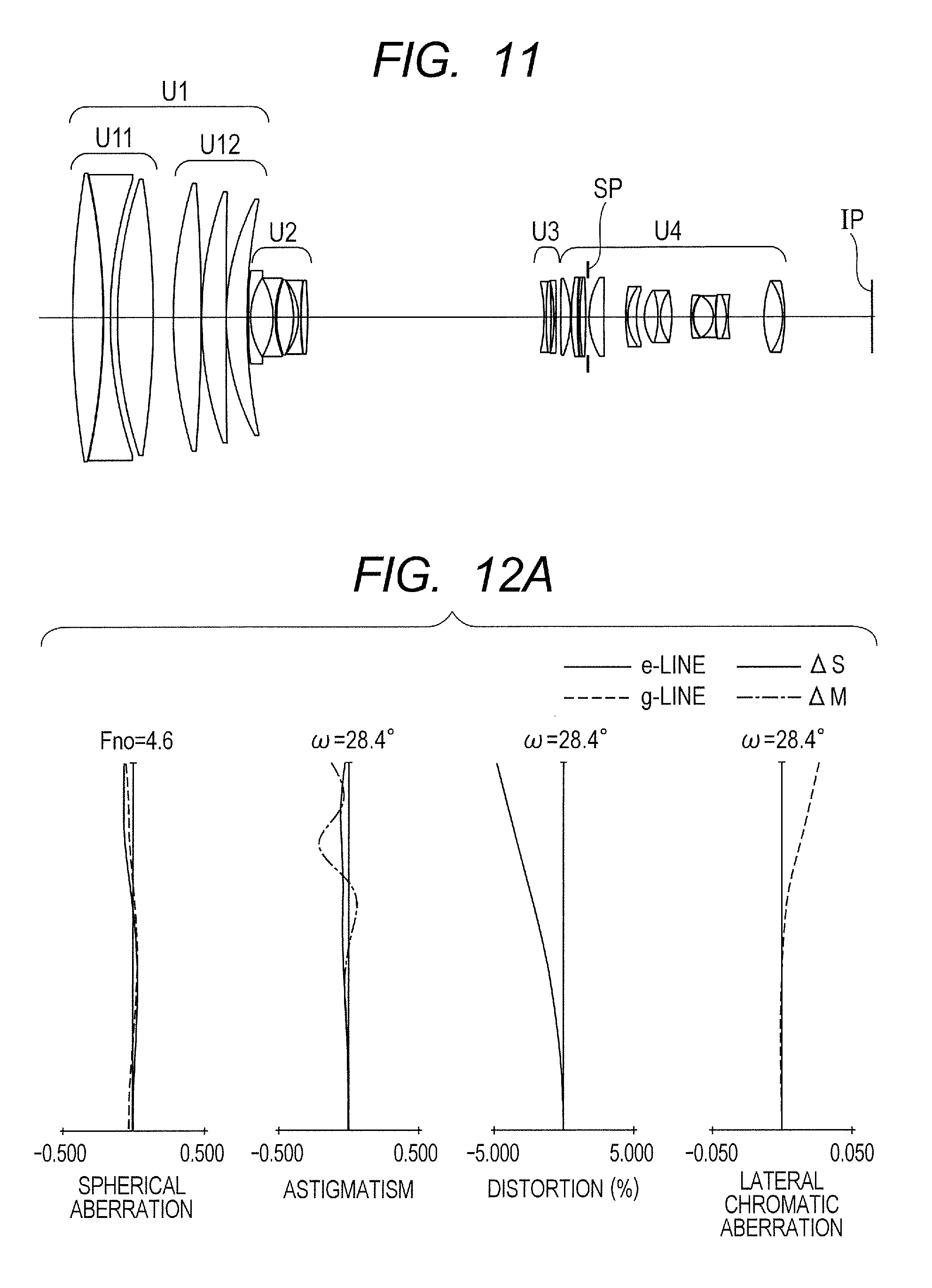
FIG. 11 is a lens cross-sectional view when focus is at infinity at a wide angle end in a zoom lens according to Embodiment 6 of the present invention.
FIG. 12A is a longitudinal aberration diagram when the focus is at infinity at the wide angle end in Embodiment 6.
FIG. 12B is a longitudinal aberration diagram when the focus is at infinity at a focal length of 180.00 mm in Embodiment 6.
FIG. 12C is a longitudinal aberration diagram when the focus is at infinity at a telephoto end in Embodiment 6.
FIG. 13 is a schematic diagram of a main part of an image pickup apparatus according to the present invention.
FIG. 14A is an optical path diagram when the focus is at an object at infinity at the wide angle end in Embodiment 6.
FIG. 14B is an optical path diagram when the focus is at the object at infinity at the telephoto end in Embodiment 6.
DESCRIPTION OF THE EMBODIMENTS
Now, features of a zoom lens according to the present invention are described.
According to the present invention, there is provided a zoom lens, including, in order from an object side to an image side: a first lens unit having a positive refractive power that does not move for zooming; a second lens unit having a negative refractive power that moves during zooming; at least one lens unit that moves during zooming; and a rear lens unit including an aperture stop, the zoom lens satisfying the following expressions: -12.00<f1/f2<-4.00 (1) -1.00<f2/(2.times.fW.times.tan(.omega._W))<-0.30 (2) where fW represents a focal length of the zoom lens at a wide angle end, f1 represents a focal length of the first lens unit, f2 represents a focal length of the second lens unit, and .omega._W represents a half angle of field at the wide angle end.
The conditional expression (1) defines a ratio of the focal length of the first lens unit U1 to the focal length of the second lens unit U2. The conditional expression (1) is satisfied to satisfactorily correct aberration variations of the zoom lens and realize both a high zoom ratio and reductions in size and weight. When the ratio exceeds the upper limit of the conditional expression (1), the focal length of the first lens unit is too short, which makes it difficult to correct a spherical aberration, an axial chromatic aberration, and the like especially at a telephoto end, and the focal length of the second lens unit is too long, which increases a moving amount of the second lens unit accompanying zooming and hence makes it difficult to realize both the high zoom ratio and the reductions in size and weight. When the ratio falls below the lower limit of the conditional expression (1), the focal length of the first lens unit is increased, which makes an effective diameter and a total lens length of the first lens unit large and makes it difficult to reduce the size and weight of the zoom lens, and the focal length of the second lens unit is too short, which makes it difficult to correct aberration variations in the spherical aberration, the axial chromatic aberration, and the like.
It is more preferred to set the conditional expression (1) as follows: -8.00<f1/f2<-5.00 (1a).
The conditional expression (2) defines a ratio of the focal length of the second lens unit U2 to an image size at the wide angle end. The conditional expression (2) is satisfied to satisfactorily correct the aberration variations of the zoom lens and realize both the high zoom ratio and the reductions in size and weight. When the ratio exceeds the upper limit of the conditional expression (2), the focal length of the second lens unit is too short, which makes it difficult to correct the aberration variations in the spherical aberration, the axial chromatic aberration, and the like. When the ratio falls below the lower limit of the conditional expression (2), the focal length of the second lens unit is too long, which increases the moving amount of the second lens unit accompanying the zooming and hence makes it difficult to realize both the high zoom ratio and the reductions in size and weight.
It is more preferred to set the conditional expression (1) as follows: -0.99<f2/(2.times.fW.times.tan(.omega._W))<-0.50 (2a).
By satisfying the above-mentioned conditional expressions, despite being a zoom lens for a large format camera, the zoom lens according to the present invention realizes the high zoom ratio and the reductions in size and weight, and attains high optical performance over an entire zoom range from the wide angle end to the telephoto end.
The zoom lens according to the present invention has a further feature of satisfying a ratio of a lateral magnification .beta.2W at the wide angle end of the second lens unit when focus is at infinity to a lateral magnification .beta.2T at the telephoto end of the second lens unit, which is defined by the conditional expression (3): 9.00<.beta.2T/.beta.2W<35.00 (3).
The conditional expression (3) is satisfied to satisfactorily correct the aberration variations of the zoom lens and allow the realization of both the high zoom ratio and the reductions in size and weight. When the ratio exceeds the upper limit of the conditional expression (3), a zoom magnification performed by the second lens unit becomes too large, which makes the refractive power of the second lens unit strong and makes it difficult to correct the spherical aberration, the axial chromatic aberration, and the like especially at the telephoto end. When the ratio falls below the lower limit of the conditional expression (3), the zoom magnification performed by the second lens unit becomes too small, which makes it difficult to achieve the high zoom ratio.
It is more preferred to set the conditional expression (3) as follows: 9.00<.beta.2T/.beta.2W<30.00 (3a).
The zoom lens according to the present invention has a further feature of satisfying a ratio of a focal length at the telephoto end of the zoom lens to the focal length of the first lens unit, which is defined by the conditional expression (4): 2.00<fT/f1<8.00 (4).
The conditional expression (4) is satisfied to allow the realization of both the high zoom ratio and increase in performance. When the ratio exceeds the upper limit of the conditional expression (4), the focal length of the first lens unit becomes too short with respect to the focal length at the telephoto end of the zoom lens, which makes it difficult to suppress the various aberrations ascribable to the first lens unit, such as the spherical aberration and the axial chromatic aberration, especially at the telephoto end. When the ratio falls below the lower limit of the conditional expression (4), the focal length of the first lens unit becomes too long with respect to the focal length at the telephoto end of the zoom lens, which moves an object point position of a zoom lens unit away and hence increases a moving amount accompanying zooming to make the high zoom ratio difficult.
It is more preferred to set the conditional expression (4) as follows: 2.00<fT/f1<7.00 (4a).
The zoom lens according to the present invention has a further feature of satisfying a ratio of the focal length f2 of the second lens unit to an air interval on an optical axis between the second lens unit and a third lens unit (interval on the optical axis between a surface on an image side of the second lens unit and a surface on an object side of the third lens unit) at the wide angle end L2W, which is defined by the conditional expression (5): -0.50<f2/L2W<-0.05 (5).
The conditional expression (5) is satisfied to satisfactorily correct the aberration variations of the zoom lens and allow the realization of both the high zoom ratio and the reductions in size and weight. When the ratio exceeds the upper limit of the conditional expression (5), the focal length of the second lens unit becomes too short with respect to the interval between the second lens unit and the third lens unit at the wide angle end, which makes it difficult to satisfactorily correct the aberration variations of the zoom lens. When the ratio falls below the lower limit of the conditional expression (5), the focal length of the second lens unit becomes too long with respect to the interval between the second lens unit and the third lens unit at the wide angle end, with the result that an enough moving amount of the second lens unit accompanying zooming cannot be secured, which makes it difficult to achieve the high zoom ratio.
It is more preferred to set the conditional expression (5) as follows: -0.40<f2/L2W<-0.10 (5a).
The zoom lens according to the present invention has a further feature of satisfying a ratio of a distance LF on the optical axis from a surface closest to the object side of the first lens unit to the aperture stop to the image size at the wide angle end, which is defined by the conditional expression (6): 4.00<LF/(fW.times.tan(2.times..omega._W))<20.00 (6).
The conditional expression (6) is satisfied to satisfactorily correct the aberration variations of the zoom lens and allow the realization of both the high zoom ratio and the reductions in size and weight. When the ratio exceeds the upper limit of the conditional expression (6), a total length of the zoom lens unit becomes too long with respect to the image size, which makes it difficult to achieve the reductions in size and weight. When the ratio falls below the lower limit of the conditional expression (6), the total length of the zoom lens unit becomes too short with respect to the image size, and the refractive power of especially the second lens unit needs to be made strong in order to secure the zoom magnification, which makes it difficult to satisfactorily correct the aberration variations of the zoom lens and achieve the high zoom ratio.
It is more preferred to set the conditional expression (6) as follows: 6.00<LF/(2.times.fW.times.tan(.omega._W))<15.00 (6a).
The zoom lens according to the present invention has a further feature of satisfying a ratio of a focal length fT at the telephoto end of the zoom lens to the image size at the wide angle end, which is defined by the conditional expression (7): 10.00<fT/(2.times.fW.times.tan(.omega._W))<40.00 (7).
The conditional expression (7) is satisfied to satisfactorily correct the aberration variations of the zoom lens and allow the realization of both an increased telephoto range and the reductions in size and weight. When the ratio exceeds the upper limit of the conditional expression (7), the focal length of the zoom lens at the telephoto end is too long with respect to the image size, which makes it difficult to correct the spherical aberration, the axial chromatic aberration, and the like especially at the telephoto end, and the effective diameter and the total lens length of the first lens unit are increased, which makes it difficult to realize the reductions in size and weight of the zoom lens. When the ratio falls below the lower limit of the conditional expression (7), the focal length of the zoom lens at the telephoto end is too short with respect to the image size, which is disadvantageous in increasing the telephoto range of the zoom lens.
It is more preferred to set the conditional expression (7) as follows: 10.00<fT/(2.times.fW.times.tan(.omega._W))<35.00 (7a).
Through the satisfaction of the above-mentioned conditional expressions in the zoom lens according to the present invention, the aberration variations may be satisfactorily corrected and both the high zoom ratio and the reductions in size and weight may be realized.
Embodiment 1
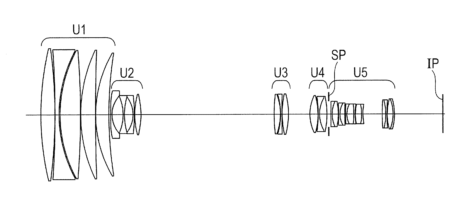
FIG. 1 is a lens cross-sectional view when focus is at an object at infinity at a wide angle end in a zoom lens according to Embodiment 1. The zoom lens according to Embodiment 1 of the present invention includes, in order from the object side, a first lens unit having a positive refractive power that does not move for zooming, a second lens unit having a negative refractive power that moves during zooming, at least one lens unit that moves during zooming, and a rear lens unit including the aperture stop.
The first lens unit U1 is a lens unit having the positive refractive power that does not move for zooming. The second lens unit U2 is a variator lens unit having a negative refractive power for zooming that moves toward the image side during zooming from the wide angle end (short focal length end) to the telephoto end (long focal length end). The "at least one lens unit that moves during zooming" in this Embodiment includes, in order from the object side to the image side, a third lens unit U3 and a fourth lens unit U4. The third lens unit U3 is a variator lens unit having a positive refractive power for zooming that moves during zooming from the wide angle end (short focal length end) to the telephoto end (long focal length end). The fourth lens unit U4 is a compensator lens unit having a positive refractive power that moves in conjunction with the second lens unit U2 and the third lens unit U3 to correct an image plane variation accompanying zooming. Moreover, the fourth lens unit U4 that moves toward the object side during focus adjustment from the object at infinity to an object at close distance. In this Embodiment, the rear lens unit includes, in order from the object side to the image side, the aperture stop SP that does not move for zooming, and a fifth lens unit (relay lens unit) having a negative refractive power that does not move for zooming. An image plane IP corresponds to an imaging plane of a solid-state image pickup element (photoelectric transducer).
The lens units in Embodiment 1 have the following configurations in order from the object side to the image side. The first lens unit U1 includes a positive lens, a negative lens, and three positive lenses. The second lens unit U2 includes three negative lenses and a positive lens. The third lens unit U3 includes a positive lens, a negative lens, and a positive lens. The fourth lens unit U4 includes a positive lens and a cemented lens of a negative lens and a positive lens. The fifth lens unit U5 includes the aperture stop SP, two cemented lenses of a negative lens and a positive lens, a cemented lens of a negative lens, a positive lens, and a negative lens, and three cemented lenses of a positive lens and a negative lens.
Numerical Embodiment corresponding to Embodiment 1 is described in <Numerical Embodiment 1> below. In the Numerical Embodiments corresponding to the Embodiments described below, respectively, r represents a curvature radius of each surface counted from the object side, d represents an interval between surfaces, and nd and .nu.d represent a refractive index and an Abbe number of each optical member. In this case, when an X axis corresponds to the optical axis, an H axis corresponds to an axis perpendicular to the optical axis, a traveling direction of light corresponds to a positive direction, a paraxial curvature radius is represented by R, a conic constant is represented by k, and aspherical coefficients are represented by A3, A4, A5, A6, A7, A8, A9, A10, A11, and A12, an aspherical surface shape is expressed by the following expression.
.times..times..times..times..times..times..times..times..times..times..ti- mes..times..times..times..times..times..times..times..times..times..times.- .times..times..times..times..times..times..times..times..times..times. ##EQU00001## where e-Z means .times.10.sup.-Z. The mark * represents the aspherical surface.
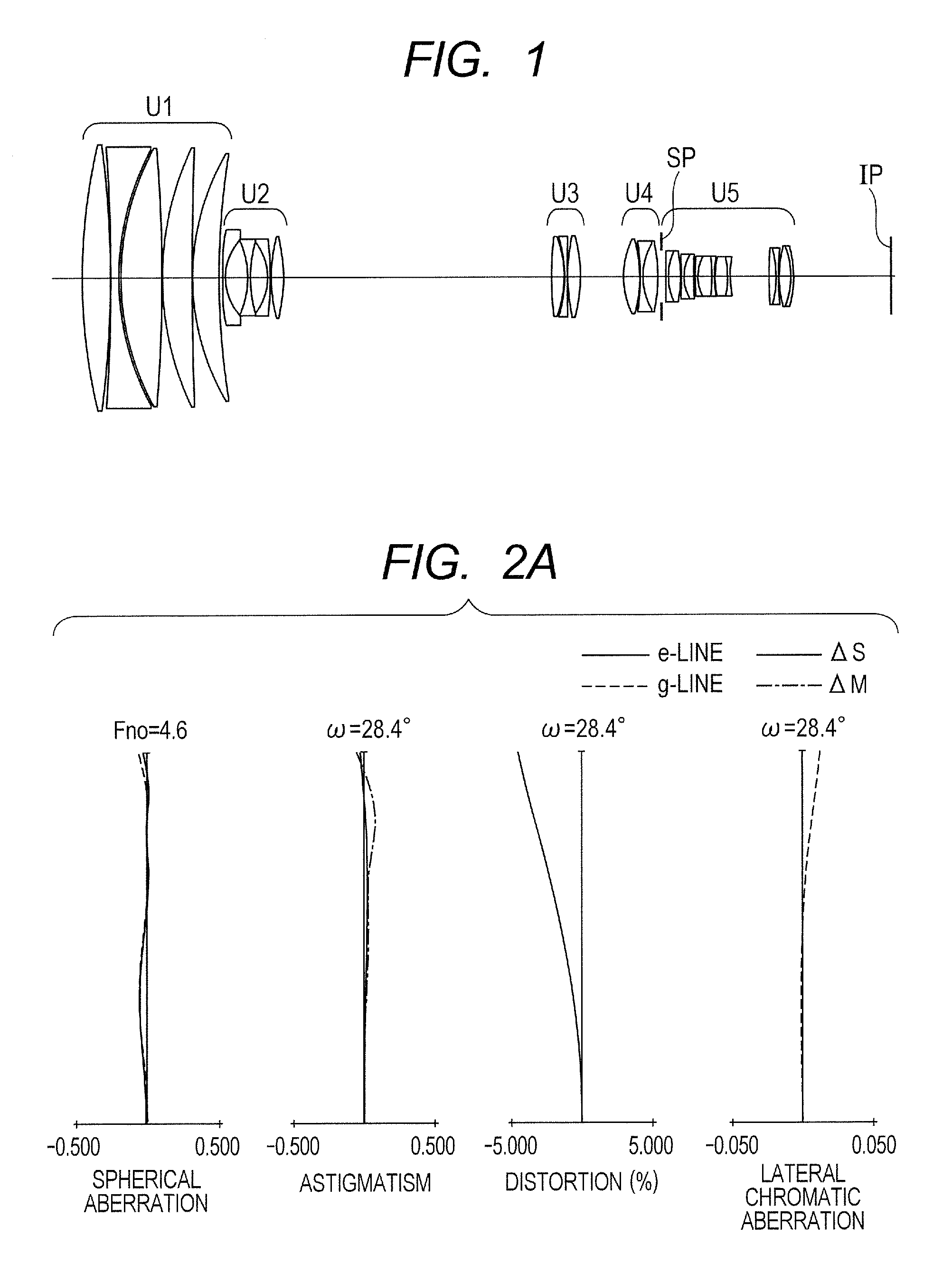
FIGS. 2A, 2B, and 2C are longitudinal aberration diagrams when the focus is at infinity at the wide angle end, a focal length of 180.00 mm, and the telephoto end, respectively, in the zoom lens according to Embodiment 1. In the figures, the value of the focal length is a value obtained when expressing Numerical Embodiment in units of mm, and the same applies to Numerical Embodiments below. In aberration diagrams, the spherical aberration is illustrated with respect to an e-Line and a g-Line. An astigmatism is illustrated on a meridional image plane (.DELTA.M) with respect to the e-Line and on a sagittal image plane (.DELTA.S) with respect to the e-Line. A lateral chromatic aberration is expressed by the g-Line. In all of the aberration diagrams, the spherical aberration, the astigmatism, the distortion, and the lateral chromatic aberration are drawn on scales of 0.5 mm, 0.5 mm, 5%, and 0.05 mm, respectively. Symbol Fno represents an F-number, and symbol a represents a half angle of field. Note that, the wide angle end and the telephoto end refer to zoom positions when the second lens unit U2 for zooming is located at both ends of a range in which the second lens unit U2 is mechanically movable on the optical axis.
Table 1 shows corresponding values of the conditional expressions of Numerical Embodiment 1. Numerical Embodiment 1 satisfies all of the conditional expressions (1) to (7). The zoom lens in this Embodiment is small and lightweight despite being the zoom lens for the large format camera, and attains the high zoom ratio with a zoom ratio of 20.0.times., a half angle of field at the wide angle end of 28.4 degrees, and a half angle of field at the telephoto end of 1.6 degrees, and the high optical performance over the entire zoom range from the wide angle end to the telephoto end.
Embodiment 2
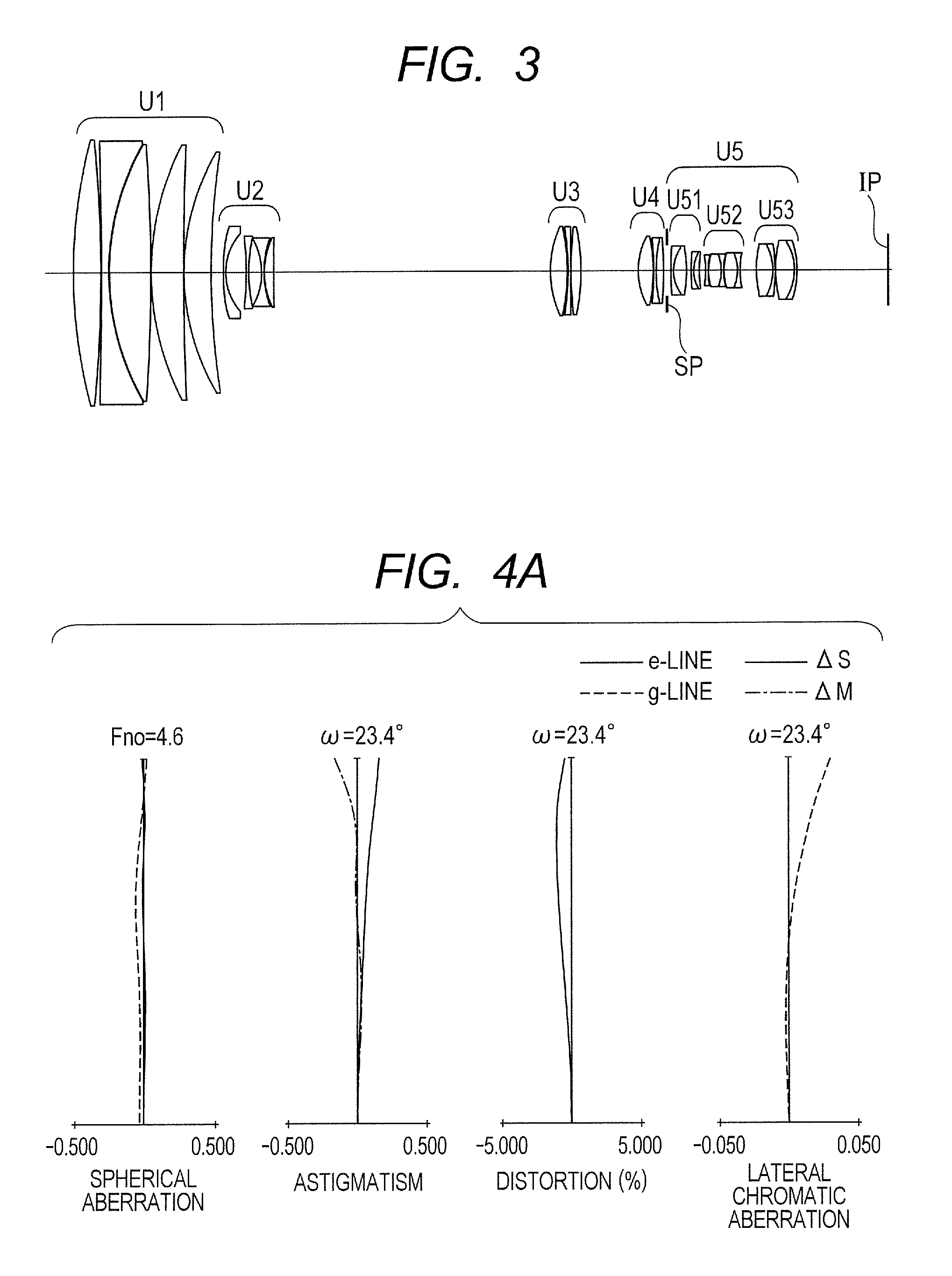
FIG. 3 is a lens cross-sectional view when the focus is at the object at infinity at the wide angle end in the zoom lens according to Embodiment 2 of the present invention. The zoom lens according to Embodiment 2 of the present invention includes, in order from the object side, a first lens unit having a positive refractive power what does not move for zooming, a second lens unit having a negative refractive power that moves during zooming, at least one lens unit that moves during zooming, and a rear lens unit including an aperture stop.
The first lens unit U1 is a lens unit having the positive refractive power that does not move for zooming. The second lens unit U2 is a variator lens unit having a negative refractive power for zooming that moves toward the image side during zooming from the wide angle end (short focal length end) to the telephoto end (long focal length end). The "at least one lens unit that moves during zooming" in this Embodiment includes, in order from the object side to the image side, a third lens unit U3 and a fourth lens unit U4. The third lens unit U3 is a variator lens unit having a positive refractive power for zooming that moves during zooming from the wide angle end (short focal length end) to the telephoto end (long focal length end). The fourth lens unit U4 is a compensator lens unit having a positive refractive power that moves in conjunction with the second lens unit U2 and the third lens unit U3 to correct the image plane variation accompanying zooming. Moreover, the fourth lens unit U4 that moves toward the object side during focusing from the object at infinity to an object at close distance. In this Embodiment, the rear lens unit is represented by U5 in the figures and includes, in order from the object side to the image side, the aperture stop SP that does not move for zooming, a first sub lens unit U51 having a negative refractive power, a third sub lens unit U53 having a positive refractive power, and a second sub lens unit U52 having a negative refractive power, which moves toward the image side during zooming.
In Embodiment 2, all the lens configurations of the first to fourth lens units are the same as those in Numerical Embodiment 1. The fifth lens unit U5 includes the aperture stop SP, the first sub lens unit U51 including two cemented lenses of a negative lens and a positive lens, the second sub lens unit U52 including a negative lens, and two cemented lenses of a positive lens and a negative lens, and the third sub lens unit U53 including two cemented lenses of a positive lens and a negative lens.
Numerical Embodiment corresponding to Embodiment 2 is described in <Numerical Embodiment 2> below.
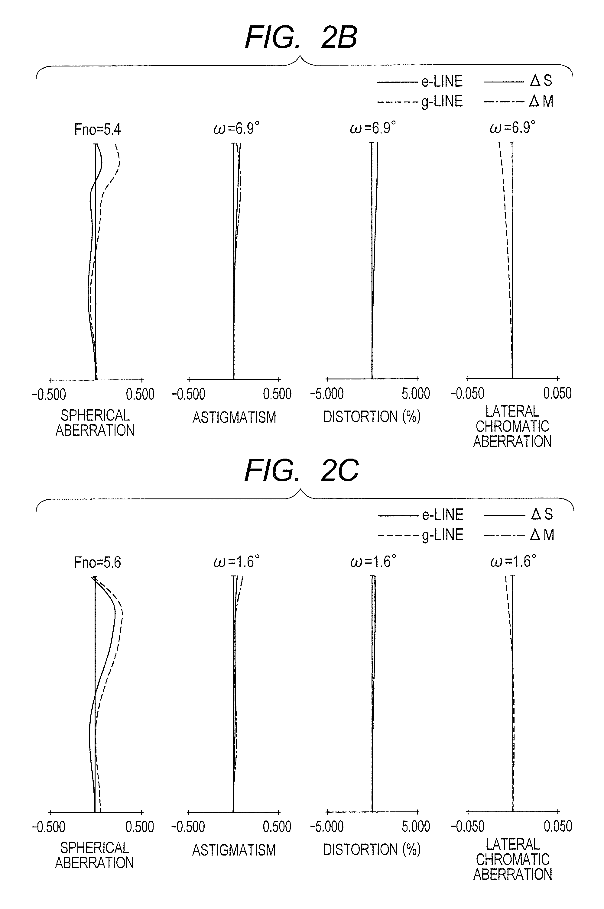
FIGS. 4A, 4B, and 4C are longitudinal aberration diagrams when the focus is at infinity at the wide angle end, a focal length of 274.00 mm, and the telephoto end, respectively, in the zoom lens according to Embodiment 2. In the figures, the value of the focal length is a value obtained when expressing Numerical Embodiment in units of mm, and the same applies to Numerical Embodiments below. In aberration diagrams, the spherical aberration is illustrated with respect to the e-Line and the g-Line. The astigmatism is illustrated on the meridional image plane (.DELTA.M) with respect to the e-Line and on the sagittal image plane (.DELTA.S) with respect to the e-Line. The lateral chromatic aberration is expressed by the g-Line. In all of the aberration diagrams, the spherical aberration, the astigmatism, a the distortion, and the lateral chromatic aberration are drawn on scales of 0.5 mm, 0.5 mm, 5%, and 0.05 mm, respectively. Symbol Fno represents the F-number, and symbol .omega. represents the half angle of field. Note that, the wide angle end and the telephoto end refer to the zoom positions when the second lens unit U2 for zooming is located at both ends of the range in which the second lens unit U2 is mechanically movable on the optical axis.
Table 1 shows corresponding values of the conditional expressions of Numerical Embodiment 2. Numerical Embodiment 2 satisfies all of the conditional expressions (1) to (7). The zoom lens in this Embodiment is small and lightweight despite being the zoom lens for the large format camera, and attains the high zoom ratio with a zoom ratio of 30.0.times., a half angle of field at the wide angle end of 23.4 degrees, and a half angle of field at the telephoto end of 0.8 degree, and the high optical performance over the entire zoom range from the wide angle end to the telephoto end.
Embodiment 3
FIG. 5 is a lens cross-sectional view when focus is at the object at infinity at the wide angle end in the zoom lens according to Embodiment 3 of the present invention. The zoom lens according to Embodiment 3 of the present invention includes, in order from the object side, a first lens unit having a positive refractive power that does not move for zooming, a second lens unit having a negative refractive power that moves during zooming, at least one lens unit that moves during zooming, and a rear lens unit including an aperture stop.
The first lens unit U1 is a lens unit having a positive refractive power that does not move for zooming. The second lens unit U2 is a variator lens unit having a negative refractive power for zooming that moves toward the image side during zooming from the wide angle end (short focal length end) to the telephoto end (long focal length end). The "at least one lens unit that moves during zooming" in this Embodiment includes, in order from the object side to the image side, a third lens unit U3 and a fourth lens unit U4. The third lens unit U3 is a variator lens unit having a positive refractive power for zooming that moves during zooming from the wide angle end (short focal length end) to the telephoto end (long focal length end). The fourth lens unit U4 is a compensator lens unit having a positive refractive power that moves in conjunction with the second lens unit U2 and the third lens unit U3 to correct the image plane variation accompanying zooming. Moreover, the fourth lens unit U4 that moves toward the object side during focus adjustment from the object at infinity to the object at close distance. In this Embodiment, the rear lens unit includes, in order from the object side to the image side, the aperture stop SP that does not move for zooming, and a fifth lens unit (relay lens unit) having a negative refractive power that does not move for zooming. The image plane IP corresponds to the imaging plane of the solid-state image pickup element (photoelectric transducer).
The lens units in Embodiment 3 have the following configurations in order from the object side to the image side. The first lens unit U1 includes a positive lens, a negative lens, and three positive lenses. The second lens unit U2 includes three negative lenses and a positive lens. The third lens unit U3 includes a positive lens, a negative lens, and a positive lens. The fourth lens unit U4 includes a positive lens and a cemented lens of a negative lens and a positive lens. The fifth lens unit U5 includes the aperture stop SP, a cemented lens of a negative lens and a positive lens, a cemented lens of a positive lens and a negative lens, a cemented lens of a negative lens, a positive lens, and a negative lens, and two cemented lenses of a positive lens and a negative lens.
Numerical Embodiment corresponding to Embodiment 3 is described in <Numerical Embodiment 3> below.
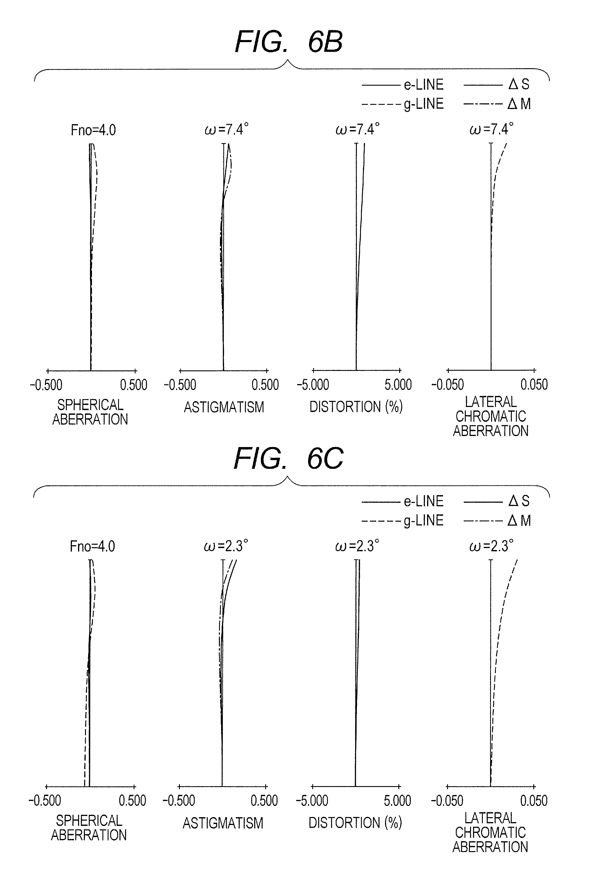
FIGS. 6A, 6B, and 6C are longitudinal aberration diagrams when the focus is at infinity at the wide angle end, a focal length of 166.00 mm, and the telephoto end, respectively, in the zoom lens according to Embodiment 3. In the figures, the value of the focal length is a value obtained when expressing Numerical Embodiment in units of mm, and the same applies to Numerical Embodiments below. In aberration diagrams, the spherical aberration is illustrated with respect to the e-Line and the g-Line. The astigmatism is illustrated on the meridional image plane (.DELTA.M) with respect to the e-Line and on the sagittal image plane (.DELTA.S) with respect to the e-Line. The lateral chromatic aberration is expressed by the g-Line. In all of the aberration diagrams, the spherical aberration, the astigmatism, the distortion, and the lateral chromatic aberration are drawn on scales of 0.5 mm, 0.5 mm, 5%, and 0.05 mm, respectively. Symbol Fno represents the F-number, and symbol .omega. represents the half angle of field. Note that, the wide angle end and the telephoto end refer to the zoom positions when the second lens unit U2 for zooming is located at both ends of the range in which the second lens unit U2 is mechanically movable on the optical axis.
Table 1 shows corresponding values of the conditional expressions of Numerical Embodiment 3. Numerical Embodiment 3 satisfies all of the conditional expressions (1) to (7). The zoom lens in this Embodiment is small and lightweight despite being the zoom lens for the large format camera, and attains the high zoom ratio with a zoom ratio of 11.0.times., a half angle of field at the wide angle end of 23.4 degrees, and a half angle of field at the telephoto end of 2.3 degrees, and the high optical performance over the entire zoom range from the wide angle end to the telephoto end.
Embodiment 4
FIG. 7 is a lens cross-sectional view when the focus is at the object at infinity at the wide angle end in the zoom lens according to Embodiment 4 of the present invention. The zoom lens according to Embodiment 4 of the present invention includes, in order from the object side, a first lens unit having a positive refractive power that does not move for zooming, a second lens unit having a negative refractive power that moves during zooming, at least one lens unit that moves during zooming, and a rear lens unit including an aperture stop.
The first lens unit U1 is a lens unit having a positive refractive power that does not move for zooming. The second lens unit U2 is a variator lens unit having a negative refractive power for zooming that moves toward the image side during zooming from the wide angle end (short focal length end) to the telephoto end (long focal length end). The "at least one lens unit that moves during zooming" in this Embodiment includes, in order from the object side to the image side, a third lens unit U3 and a fourth lens unit U4. The third lens unit U3 is a variator lens unit having a positive refractive power for zooming that moves during zooming from the wide angle end (short focal length end) to the telephoto end (long focal length end). The fourth lens unit U4 is a compensator lens unit having a positive refractive power that moves in conjunction with the second lens unit U2 and the third lens unit U3 to correct the image plane variation accompanying zooming. Moreover, the fourth lens unit U4 that moves toward the object side during focus adjustment from the object at infinity to the object at close distance. In this Embodiment, the rear lens unit includes, in order from the object side to the image side, the aperture stop SP that does not move for zooming, and a fifth lens unit (relay lens unit) having a negative refractive power that does not move for zooming. The image plane IP corresponds to the imaging plane of the solid-state image pickup element (photoelectric transducer).
The lens units in Embodiment 4 have the following configurations in order from the object side to the image side.
The first lens unit U1 includes a positive lens, a negative lens, and three positive lenses. The second lens unit U2 includes three negative lenses and a positive lens. The third lens unit U3 includes a positive lens, a negative lens, and a positive lens. The fourth lens unit U4 includes a positive lens and a cemented lens of a negative lens and a positive lens. The fifth lens unit U5 includes the aperture stop SP, two cemented lenses of a negative lens and a positive lens, a cemented lens of a negative lens, a positive lens, and a negative lens, and three cemented lenses of a positive lens and a negative lens. The lens configurations are the same as those in Embodiment 1.
Numerical Embodiment corresponding to Embodiment 4 is described in <Numerical Embodiment 4> below.
FIGS. 8A, 8B, and 8C are longitudinal aberration diagrams when the focus is at infinity at the wide angle end, a focal length of 180.00 mm, and the telephoto end, respectively, in the zoom lens according to Embodiment 4. In the figures, the value of the focal length is a value obtained when expressing Numerical Embodiment in units of mm, and the same applies to Numerical Embodiments below. In aberration diagrams, the spherical aberration is illustrated with respect to the e-Line and the g-Line. The astigmatism is illustrated on the meridional image plane (.DELTA.M) with respect to the e-Line and on the sagittal image plane (.DELTA.S) with respect to the e-Line. The lateral chromatic aberration is expressed by the g-Line. In all of the aberration diagrams, the spherical aberration, the astigmatism, the distortion, and the lateral chromatic aberration are drawn on scales of 0.5 mm, 0.5 mm, 5%, and 0.05 mm, respectively. Symbol Fno represents the F-number, and symbol .omega. represents the half angle of field. Note that, the wide angle end and the telephoto end refer to the zoom positions when the second lens unit U2 for zooming is located at both ends of the range in which the second lens unit U2 is mechanically movable on the optical axis.
Table 1 shows corresponding values of the conditional expressions of Numerical Embodiment 4. Numerical Embodiment 4 satisfies all of the conditional expressions (1) to (7). The zoom lens in this Embodiment is small and lightweight despite being the zoom lens for the large format camera, and attains the high zoom ratio with a zoom ratio of 20.0.times., a half angle of field at the wide angle end of 20.3 degrees, and a half angle of field at the telephoto end of 1.1 degrees, and the high optical performance over the entire zoom range from the wide angle end to the telephoto end.
Embodiment 5
FIG. 9 is a lens cross-sectional view when focus is at the object at infinity at the wide angle end in the zoom lens according to Embodiment 5. The zoom lens according to Embodiment 5 of the present invention includes, in order from the object side, a first lens unit having a positive refractive power that does not move for zooming, a second lens unit having a negative refractive power that moves during zooming, at least one lens unit that moves during zooming, and a rear lens unit including an aperture stop.
FIGS. 14A and 14B are optical path diagrams when the focus is at the object at infinity at the wide angle end and the telephoto end, respectively, in Embodiment 5. An axial ray passing through the second sub lens unit U52 is substantially afocal, and a height of the axial ray from the optical axis is substantially constant at the wide angle end and the telephoto end. Therefore, an effect of the second sub lens unit U52 being moved during zooming on variations during zooming in axial aberrations such as the spherical aberration and the axial chromatic aberration is small. On the other hand, a height of an off-axial ray passing through the second sub lens unit U52 from the optical axis is higher at the telephoto end than at the wide angle end. Therefore, the second sub lens unit U52 may be moved during zooming to effectively correct the variations during zooming in off-axial aberrations such as a field curvature and the lateral chromatic aberration.
The first lens unit U1 is a lens unit having the positive refractive power that does not move for zooming. The second lens unit U2 is a variator lens unit having a negative refractive power for zooming that moves toward the image side during zooming from the wide angle end (short focal length end) to the telephoto end (long focal length end). The "at least one lens unit that moves during zooming" in this Embodiment includes, in order from the object side to the image side, a third lens unit U3 and a fourth lens unit U4. The third lens unit U3 is a variator lens unit having a positive refractive power for zooming that moves during zooming from the wide angle end (short focal length end) to the telephoto end (long focal length end). The fourth lens unit U4 is a compensator lens unit having a positive refractive power that moves in conjunction with the second lens unit U2 and the third lens unit U3 to correct the image plane variation accompanying zooming. Moreover, the fourth lens unit U4 that moves toward the object side during focusing from the object at infinity to an object at close distance. In this Embodiment, the rear lens unit is represented by U5 in the figures and includes, in order from the object side to the image side, the aperture stop SP that does not move for zooming, a first sub lens unit U51 having a negative refractive power, a third sub lens unit U53 having a positive refractive power, and a second sub lens unit U52 having a negative refractive power that moves toward the image side during zooming.
The lens units in Embodiment 5 have the following configurations in order from the object side to the image side. The first lens unit U1 includes a positive lens, a negative lens, and three positive lenses. The second lens unit U2 includes three negative lenses and a positive lens. The third lens unit U3 includes a positive lens, a negative lens, and a positive lens. The fourth lens unit U4 includes a positive lens and a cemented lens of a negative lens and a positive lens. The fifth lens unit U5 includes the aperture stop 5P, a first sub lens unit U51 including two cemented lenses of a negative lens and a positive lens, a second sub lens unit U52 including a cemented lens of a negative lens and a positive lens, and a cemented lens of a negative lens, a positive lens, and a negative lens, and a third sub lens unit U53 including two cemented lenses of a positive lens and a negative lens.
Numerical Embodiment corresponding to Embodiment 5 is described in <Numerical Embodiment 5> below.
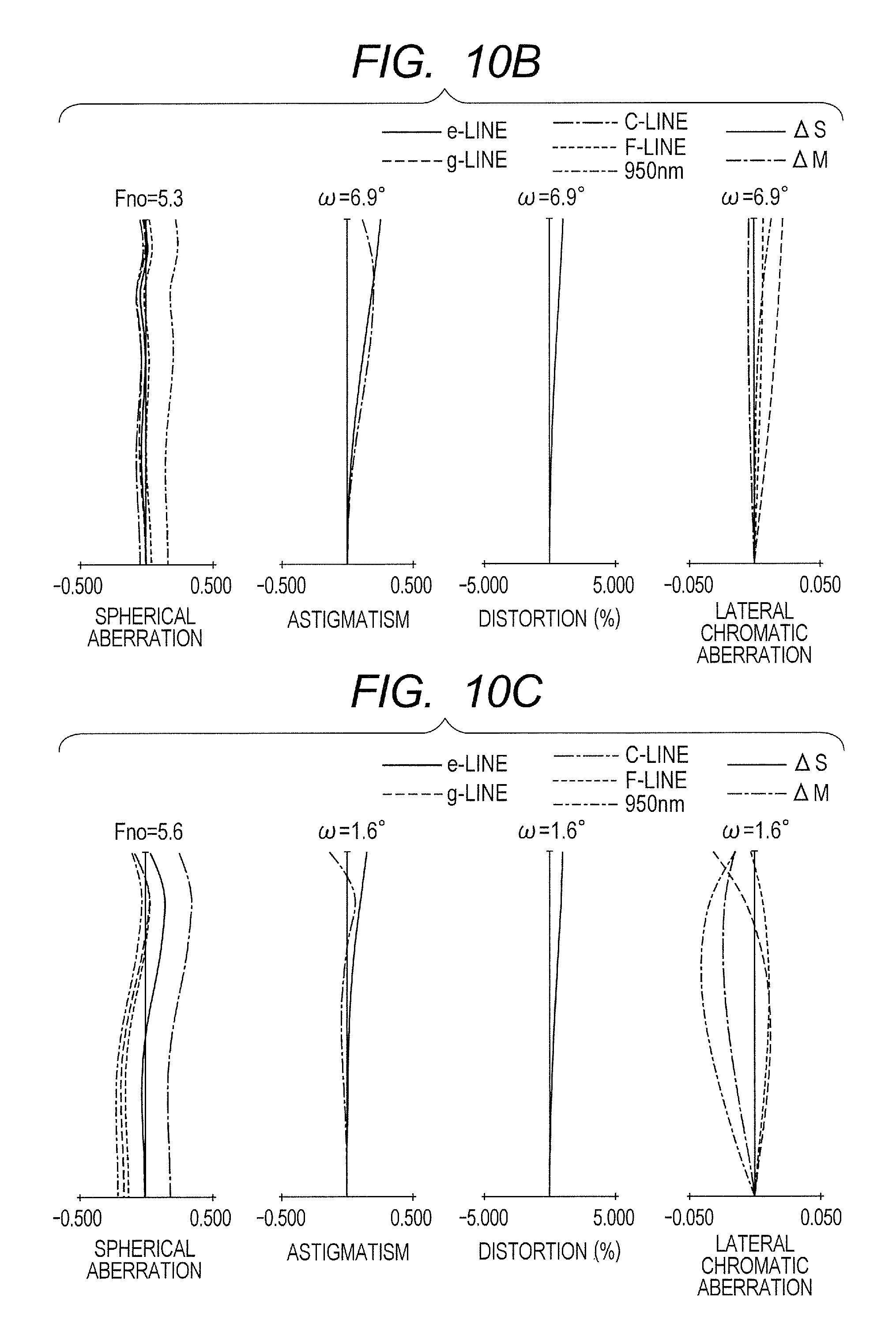
FIGS. 10A, 10B, and 10C are longitudinal aberration diagrams when the focus is at infinity at the wide angle end, a focal length of 180.00 mm, and the telephoto end, respectively, in the zoom lens according to Embodiment 5. In the figures, the value of the focal length is a value obtained when expressing Numerical Embodiment in units of mm, and the same applies to Numerical Embodiments below. In aberration diagrams, the spherical aberration is illustrated with respect to the e-Line, the g-Line, a C-Line, an F-Line, and 950 nm. The astigmatism is illustrated on the meridional image plane (.DELTA.M) with respect to the e-Line and on the sagittal image plane (.DELTA.S) with respect to the e-Line. The lateral chromatic aberration is expressed by the g-Line, the C-Line, the F-Line, and 950 nm. In all of the aberration diagrams, the spherical aberration, the astigmatism, the distortion, and the lateral chromatic aberration are drawn on scales of 0.5 mm, 0.5 mm, 5%, and 0.05 mm, respectively. Symbol Fno represents the F-number, and symbol .omega. represents the half angle of field. Note that, the wide angle end and the telephoto end refer to the zoom positions when the second lens unit U2 for zooming is located at both ends of the range in which the second lens unit U2 is mechanically movable on the optical axis.
Table 1 shows corresponding values of the conditional expressions of Numerical Embodiment 5. Numerical Embodiment 5 satisfies all of the conditional expressions (1) to (7). The zoom lens in this Embodiment is small and lightweight despite being the zoom lens for the large format camera, and attains the high zoom ratio with a zoom ratio of 20.0.times., a half angle of field at the wide angle end of 28.4 degrees, and a half angle of field at the telephoto end of 1.6 degrees, and the high optical performance over the entire zoom range from the wide angle end to the telephoto end.
Embodiment 6
FIG. 11 is a lens cross-sectional view when the focus is at the object at infinity at the wide angle end in the zoom lens according to Embodiment 6. The zoom lens according to Embodiment 6 of the present invention includes, in order from the object side, a first lens unit having a positive refractive power that does not move for zooming, a second lens unit having a negative refractive power that moves during zooming, at least one lens unit that moves during zooming, and a rear lens unit including an aperture stop.
The first lens unit U1 is a lens unit having a positive refractive power that does not move for zooming. Moreover, the first lens unit U1 includes a first sub lens unit U11 and a second sub lens unit U12, and the second sub lens unit U12 that moves toward the object side during focus adjustment from the object at infinity to the object at close distance. The second lens unit U2 that moves during zooming to play a role of zooming. The "at least one lens unit that moves during zooming" in this Embodiment is a third lens unit U3 that moves during zooming to play a role of correcting the image plane variation accompanying zooming. In this Embodiment, the rear lens unit includes a fourth lens unit U4 (relay lens unit) that does not move for zooming, includes the aperture stop SP, and has a positive refractive power.
In Embodiment 6, the first lens unit U1 includes the first sub lens unit U11 including a positive lens, a negative lens, and a positive lens, and the second sub lens unit U12 including three positive lenses that move during focus adjustment. The second lens unit U2 includes two negative lenses, a positive lens, a negative lens, and a positive lens. The third lens unit U3 includes a cemented lens of a negative lens and a positive lens, and a negative lens. The fourth lens unit U4 includes two positive lenses, a cemented lens of a negative lens and a positive lens, the aperture stop SP, a positive lens, a cemented lens of a negative lens and a positive lens, a cemented lens of a positive lens, a negative lens, and a positive lens, a negative lens, and three cemented lenses of a positive lens and a negative lens.
The zoom lens in Embodiment 6 attains a zoom ratio of 20.0.times., a half angle of field at the wide angle end of 28.4 degrees, and a half angle of field at the telephoto end of 1.6 degrees.
Numerical Embodiment corresponding to Embodiment 6 is described in <Numerical Embodiment 6> below.
FIGS. 12A, 12B, and 12C are longitudinal aberration diagrams when the focus is at infinity at the wide angle end, a focal length of 180.00 mm, and the telephoto end, respectively, in the zoom lens according to Embodiment 6. In the figures, the value of the focal length is a value obtained when expressing Numerical Embodiment in units of mm, and the same applies to Numerical Embodiments below. In aberration diagrams, the spherical aberration is illustrated with respect to the e-Line and the g-Line. The astigmatism is illustrated on the meridional image plane (.DELTA.M) with respect to the e-Line and on the sagittal image plane (.DELTA.S) with respect to the e-Line. The lateral chromatic aberration is expressed by the g-Line. In all of the aberration diagrams, the spherical aberration, the astigmatism, the distortion, and the lateral chromatic aberration are drawn on scales of 0.5 mm, 0.5 mm, 5%, and 0.05 mm, respectively. Symbol Fno represents the F-number, and symbol .omega. represents the half angle of field. Note that, the wide angle end and the telephoto end refer to the zoom positions when the second lens unit U2 for zooming is located at both ends of the range in which the second lens unit U2 is mechanically movable on the optical axis.
Table 1 shows corresponding values of the conditional expressions of Numerical Embodiment 6. Numerical Embodiment 6 satisfies all of the conditional expressions (1) to (7). The zoom lens in this Embodiment is small and lightweight despite being the zoom lens for the large format camera, and attains the high zoom ratio with a zoom ratio of 20.0.times., a half angle of field at the wide angle end of 28.4 degrees, and a half angle of field at the telephoto end of 1.6 degrees, and the high optical performance over the entire zoom range from the wide angle end to the telephoto end.
Embodiment 7
In Embodiment 7, referring to FIG. 13, a brief description is given of an image pickup apparatus (television camera system) using the zoom lens according to each of Embodiments (Numerical Embodiments) as a photographing optical system. FIG. 13 is a schematic diagram of a main part of the image pickup apparatus according to the present invention. In FIG. 13, an image pickup apparatus 125 includes a zoom lens 101 according to any one of Numerical Embodiments 1 to 6, and a camera 124. The zoom lens 101 is removably mounted to the camera 124. The image pickup apparatus 125 is constructed by mounting the zoom lens 101 to the camera 124.
The zoom lens 101 includes a first lens unit F, a zoom lens unit LZ, and a rear lens unit R for imaging. The first lens unit F or the zoom lens unit LZ includes a lens unit for focus adjustment. The zoom lens unit LZ includes a lens unit that moves on the optical axis for zooming and a lens unit that moves on the optical axis for correcting the image plane variation accompanying zooming. The rear lens unit R for imaging includes the aperture stop SP.
A lens unit IE that moves in the focal length range of the entire system of the zoom lens 101.
Drive mechanisms 114 and 115, such as a helicoid and a cam, drive the first lens unit F and the zoom lens unit LZ in an optical axis direction, respectively. Motors (drive units) 116 to 118 electrically drive the drive mechanisms 114 and 115 and the aperture stop SP. Detectors 119 to 121, such as an encoder, a potentiometer, or a photo-sensor that detect positions of the first lens unit F and the zoom lens unit LZ on the optical axis, and an aperture diameter of the aperture stop SP. The camera 124 includes a glass block 109, which corresponds to an optical filter or a color separation prism provided within the camera 124. Further, the camera 124 includes a solid state image pickup element (photoelectric transducer) 110, such as a charge-coupled device (CCD) sensor or a complementary metal-oxide semiconductor (CMOS) sensor. The solid state image pickup element 110 that receives a subject image formed by the zoom lens 101. Further, central processing units (CPUs) 111 and 122 control the driving of the camera 124 and the zoom lens 101.
By applying the zoom lens according to the present invention to a television camera as described above, the image pickup apparatus having the high optical performance may be realized.
Numerical Embodiment 1
TABLE-US-00001 Surface data Surface Effective number r d nd .nu.d diameter 1 322.060 15.85 1.43387 95.1 144.38 2 -561.835 0.20 1 142.80 3 -1053.084 4.50 1.72916 54.7 141.67 4 150.529 1.17 1 138.78 5 150.029 23.11 1.43387 95.1 139.70 6 -872.351 0.20 1 139.89 7 167.827 16.77 1.43387 95.1 140.27 8 2068.554 0.20 1 139.60 9 136.426 14.91 1.43387 95.1 133.89 10 438.209 (Variable) 1 132.53 11* 632.290 1.50 1.53715 74.8 51.90 12 31.090 12.63 1 41.46 13 -49.863 1.50 1.53715 74.8 41.14 14 72.781 9.70 1 38.75 15 -31.818 1.50 1.53715 74.8 38.68 16 -179.190 0.50 1 41.60 17 86.827 7.04 1.65412 39.7 44.03 18* -71.085 (Variable) 1 44.17 19 183.198 7.12 1.51742 52.4 43.04 20 -62.377 0.20 1 43.13 21 -76.444 1.50 1.90200 25.1 42.81 22 851.985 0.20 1 43.35 23* 87.377 7.20 1.51742 52.4 43.94 24 -85.691 (Variable) 1 44.05 25 47.110 9.21 1.53715 74.8 40.20 26 -75.770 0.20 1 39.46 27* -161.231 1.50 1.77250 49.6 38.03 28 36.474 8.42 1.53715 74.8 35.50 29 -88.021 (Variable) 1 35.03 30 (Stop) .infin. 2.50 1 29.14 31 -3203.415 1.50 1.88300 40.8 27.29 32 33.206 7.00 1.59270 -35.3 25.76 33 -59.743 0.20 1 24.86 34 -341.630 1.50 1.88300 40.8 23.83 35 23.827 5.46 1.59270 35.3 22.22 36 214.783 0.90 1 21.50 37 255.490 1.50 1.88300 40.8 21.23 38 23.670 7.96 1.85478 24.8 20.46 39 -82.946 1.50 1.88300 40.8 20.25 40 69.429 0.20 1 20.42 41 51.937 7.06 1.85478 24.8 20.61 42 -52.719 1.50 1.88300 40.8 20.68 43 57.414 21.89 1 20.75 44 263.495 3.94 1.53172 48.8 28.76 45 -61.741 1.50 1.95906 17.5 29.12 46 192.038 0.20 1 30.14 47 62.143 6.68 1.53172 48.8 31.30 48 -46.182 1.50 1.95906 17.5 31.75 49 -64.474 1 32.54 Image plane .infin. Aspherical surface data Eleventh surface K = 0.00000e+000 A4 = 2.87407e-006 A6 = -9.87572e-010 A8 = 2.85037e-012 A10 = -4.14374e-015 A12 = 3.90023e-018 Eighteenth surface K = 0.00000e+000 A4 = 2.92304e-006 A6 = 1.18582e-009 A8 = -4.62922e-013 A10 = 1.31730e-015 A12 = -9.42211e-019 Twenty-third surface K = 0.00000e+000 A4 = -1.91661e-006 A6 = -4.52468e-010 A8 = 4.64191e-013 A10 = -1.09395e-015 A12 = 5.73853e-019 Twenty-seventh surface K = 0.00000e+000 A4 = -1.73820e-006 A6 = 2.71278e-010 A8 = 2.02182e-012 A10 = -6.46061e-015 A12 = 6.25473e-018 Various data Zoom ratio 20.00 Wide angle Intermediate Telephoto Focal length 40.00 180.00 800.01 F-number 4.60 5.36 5.60 Angle of field 28.42 6.86 1.55 Image height 21.65 21.65 21.65 Total lens length 455.50 455.50 455.50 BF 55.06 55.06 55.06 d10 2.00 98.90 151.82 d18 150.89 51.21 1.50 d24 24.24 14.85 17.13 d29 1.99 14.16 8.67 Entrance pupil position 107.23 519.10 2512.83 Exit pupil position -62.78 -62.78 -62.78 Front principal point position 133.65 424.16 -2118.25 Rear principal point position 15.06 -124.94 -744.95 Zoom lens unit data Lens First Focal structure Front principal Rear principal Unit surface length length point position point position 1 1 220.00 76.90 33.42 -20.78 2 11 -33.00 34.38 3.10 -30.02 3 19 100.00 16.22 7.40 -3.43 4 25 77.00 19.33 3.44 -9.65 5 30 -49.29 74.49 4.50 -58.66
Numerical Embodiment 2
TABLE-US-00002 Surface data Surface Effective number r d nd .nu.d diameter 1 309.463 16.60 1.43387 95.1 154.77 2 -796.747 0.20 1 154.24 3 -3147.021 4.50 1.72916 54.7 153.21 4 153.581 0.29 1 148.91 5 152.879 25.01 1.43387 95.1 149.17 6 -1082.423 0.20 1 149.20 7 166.085 19.51 1.43387 95.1 148.33 8 1728.054 0.20 1 147.17 9 141.414 16.30 1.43387 95.1 139.79 10 469.895 (Variable) 1 137.94 11* 140.220 1.50 1.53715 74.8 53.82 12 35.668 12.40 1 45.60 13 -173.953 1.50 1.53715 74.8 42.36 14 98.820 7.67 1 39.65 15 -40.525 1.50 1.59522 67.7 39.27 16 59.876 0.19 1 39.89 17 48.642 5.52 1.72047 34.7 40.57 18* -1495.589 (Variable) 1 40.44 19 64.955 10.22 1.43875 94.9 52.76 20 -122.301 0.20 1 52.56 21 -171.372 1.70 2.00069 25.5 52.17 22 28261.585 0.20 1 52.09 23* 172.482 5.93 1.49700 81.5 52.02 24 -129.888 (Variable) 1 51.89 25 44.114 8.96 1.49700 81.5 41.51 26 -97.659 0.20 1 40.77 27* -310.687 1.50 1.77250 49.6 39.23 28 87.110 4.54 1.49700 81.5 37.40 29 -261.144 (Variable) 1 36.63 30 (Stop) .infin. 2.50 1 30.68 31 242.016 1.50 1.88300 40.8 28.2 32 23.168 7.96 1.59270 35.3 25.77 33 -69.912 2.68 1 24.75 34 107.234 1.50 1.88300 40.8 21.13 35 20.680 3.42 1.59270 35.3 19.36 36 63.981 (Variable) 1 18.63 37 -56.252 1.50 1.88300 40.8 17.34 38 41.889 0.19 1 17.00 39 32.689 7.69 1.85478 24.8 17.07 40 -26.389 1.50 1.88300 40.8 17.66 41 36.873 0.20 1 18.23 42 36.185 8.15 1.85478 24.8 18.43 43 -24.954 1.50 1.88300 40.8 19.12 44 48.974 (Variable) 1 19.77 45 63.097 9.88 1.53172 48.8 26.98 46 -32.051 1.50 1.95906 17.5 28.36 47 -103.359 0.20 1 29.93 48 70.421 11.48 1.53172 48.8 31.63 49 -30.910 1.50 1.95906 17.5 32.53 50 -54.654 1 33.90 Image plane .infin. Aspherical surface data Eleventh surface K = 0.00000e+000 A4 = 5.19683e-007 A6 = 1.73681e-009 A8 = -1.50609e-012 A10 = 1.43359e-015 A12 = 1.52701e-019 Eighteenth surface K = 0.00000e+000 A4 = 2.12056e-006 A6 = 3.22748e-009 A8 = -4.68497e-012 A10 = 1.02585e-014 A12 = -8.52497e-018 Twenty-third surface K = 0.00000e+000 A4 = -1.18543e-006 A6 = -8.02896e-011 A8 = -8.20631e-014 A10 = 1.16608e-016 A12 = -6.41427e-020 Twenty-seventh surface K = 0.00000e+000 A4 = -1.70895e-006 A6 = 3.36974e-010 A8 = -6.60188e-013 A10 = 1.19349e-015 A12 = -1.04914e-018 Various data Zoom ratio 30.00 Wide angle Intermediate Telephoto Focal length 50.00 274.00 1500.08 F-number 4.60 5.53 9.82 Angle of field 23.41 4.52 0.83 Image height 21.65 21.65 21.65 Total lens length 491.04 491.04 491.04 BF 55.11 55.11 55.11 d10 7.38 107.00 140.37 d18 166.85 72.50 1.50 d24 34.64 18.19 65.96 d29 2.00 13.19 3.05 d36 3.85 6.90 12.65 d44 9.80 6.75 1.00 Entrance pupil position 139.06 842.29 5080.32 Exit pupil position -77.29 -69.39 -55.99 Front principal point position 170.17 513.30 -13673.40 Rear principal point position 5.11 -218.89 -1444.97 Zoom lens unit data Lens First Focal structure Front principal Rear principal Unit surface length length point position point position 1 1 215.00 82.80 32.99 -25.39 2 11 -30.50 30.29 10.33 -14.22 3 19 92.50 18.24 4.95 -7.75 4 25 80.00 15.20 0.96 -9.21 5 30 -63.66 19.57 10.42 -3.00 6 37 -30.09 20.74 6.19 -4.18 7 45 67.56 24.57 7.17 -9.40
Numerical Embodiment 3
TABLE-US-00003 Surface data Surface Effective number r d nd .nu.d diameter 1 323.583 20.69 1.43387 95.1 154.53 2 -474.993 0.20 1 151.81 3 -548.786 4.50 1.72916 54.7 150.72 4 177.844 4.74 1 141.29 5 177.453 22.50 1.43387 95.1 141.41 6 -559.198 0.20 1 140.89 7 213.284 16.10 1.43387 95.1 137.41 8 -3234.199 0.20 1 136.58 9 153.517 14.92 1.43387 95.1 131.56 10 558.979 (Variable) 1 129.61 11* 391.648 1.50 1.53715 74.8 58.53 12 35.008 13.78 1 48.28 13 -76.088 1.50 1.53715 74.8 48.11 14 208.735 8.23 1 46.76 15 -45.774 1.50 1.53715 74.8 46.66 16 -175.487 0.50 1 48.45 17 116.939 6.28 1.80000 29.8 49.87 18* -316.657 (Variable) 1 49.76 19 137.482 8.29 1.51742 52.4 45.15 20 -60.464 0.63 1 45.33 21 -65.600 1.50 1.90200 25.1 45.02 22 -489.271 0.20 1 45.98 23* 108.086 6.81 1.51742 52.4 46.80 24 -102.805 (Variable) 1 47.00 25 44.079 12.04 1.53715 74.8 45.45 26 -86.609 0.20 1 44.12 27* -258.212 1.50 1.77250 49.6 41.86 28 33.953 9.60 1.53715 74.8 38.00 29 -101.992 (Variable) 1 37.33 30 (Stop) .infin. 2.50 1 27.69 31 -128.577 1.50 1.88300 40.8 26.30 32 29.387 6.38 1.59270 35.3 24.91 33 -43.762 0.20 1 24.61 34 -489.500 1.50 1.88300 40.8 23.38 35 -155.569 1.00 1.59270 35.3 22.99 36 27.201 3.44 1 22.45 37 775.668 1.50 1.88300 40.8 22.89 38 20.246 6.56 1.85478 24.8 23.92 39 -107.871 1.50 1.88300 40.8 24.35 40 113.856 0.20 1 24.98 41 29.221 6.75 1.85478 24.8 26.76 42 60.858 1.50 1.88300 40.8 25.92 43 33.922 19.54 1 25.47 44 39.993 12.31 1.53172 48.8 34.04 45 -34.383 1.50 1.95906 17.5 33.72 46 -170.719 1 34.66 Image plane .infin. Aspherical surface data Eleventh surface K = 0.00000e+000 A4 = 1.34967e-006 A6 = -4.59445e-010 A6 = 5.39719e-014 A10 = 1.48200e-016 A12 = -4.446736e-020 Eighteenth surface K = 0.00000e+000 A4 = 1.03240e-006 A6 = -5.48948e-011 A8 = -7.61369e-014 A10 = 2.71026e-016 A12 = -1.43650e-019 Twenty-third surface K = 0.00000e+000 A4 = -1.39189e-006 A6 = -2.09025e-010 A8 = -7.86430e-013 A10 = 1.16795e-015 A12 = -9.06787e-019 Twenty-seventh surface K = 0.00000e+000 A4 = -2.01409e-006 A6 = 5.39440e-010 A8 = 9.28833e-013 A10 = -2.69874e-015 A12 = 1.98395e-018 Various data Zoom ratio 11.00 Wide angle Intermediate Telephoto Focal length 50.00 166.00 550.09 F-number 4.00 4.00 4.00 Angle of field 23.41 7.43 2.25 Image height 21.65 21.65 21.65 Total lens length 449.62 449.62 449.62 BF 49.91 49.91 49.91 d10 16.97 97.72 149.35 d18 139.31 57.30 6.46 d24 15.43 9.34 12.76 d29 2.00 9.35 5.14 Entrance pupil position 154.03 508.75 1723.06 Exit pupil position -52.31 -52.31 -52.31 Front principal point position 179.58 405.18 -687.13 Rear principal point position -0.09 -116.09 -500.18 Zoom lens Unit data Lens First Focal structure Front principal Rear principal Unit surface length length point position point position 1 1 230.00 84.05 43.02 -17.19 2 11 -42.42 33.30 4.60 -24.61 3 19 100.00 17.43 6.78 -5.07 4 25 75.00 23.34 3.28 -12.58 5 30 -51.64 67.88 1.99 -50.39
Numerical Embodiment 4
TABLE-US-00004 Surface data Surface Effective number r d nd .nu.d diameter 1 323.793 16.54 1.43387 95.1 142.87 2 -461.112 0.20 1 142.45 3 -897.246 4.50 1.72916 54.7 141.46 4 150.093 0.92 1 138.42 5 149.042 23.55 1.43387 95.1 139.19 6 -746.449 0.20 1 139.36 7 170.564 16.32 1.43387 95.1 139.35 8 2093.602 0.20 1 138.66 9 140.468 14.48 1.43387 95.1 133.05 10 466.164 (Variable) 1 131.70 11* 248.924 1.50 1.53715 74.8 35.97 12 30.699 10.17 1 31.49 13 -34.307 1.50 1.53715 74.8 29.39 14 73.732 7.15 1 28.62 15 -29.328 1.50 1.53715 74.8 28.67 16 2107.239 0.31 1 30.76 17 91.584 5.58 1.65412 39.7 32.35 18* -48.495 (Variable) 1 32.96 19 201.356 6.03 1.51742 52.4 40.56 20 -70.340 0.20 1 40.68 21 -73.507 1.50 1.90200 25.1 40.61 22 1122.574 0.20 1 41.32 23* 80.205 7.48 1.51742 52.4 42.15 24 -75.285 (Variable) 1 42.32 25 46.671 9.09 1.53715 74.8 39.63 26 -74.476 0.20 1 38.93 27* -143.645 1.50 1.77250 49.6 37.70 28 39.768 7.92 1.53715 74.8 35.49 29 -91.081 (Variable) 1 35.07 30 (Stop) .infin. 2.50 1 28.26 31 34080.822 1.50 1.88300 40.8 26.53 32 28.636 7.28 1.59270 35.3 24.99 33 -56.012 0.20 1 24.24 34 -431.425 1.50 1.88300 40.8 23.26 35 25.163 4.01 1.59270 35.3 21.87 36 151.721 11.70 1 21.45 37 317.930 1.50 1.88300 40.8 19.03 38 21.630 5.15 1.85478 24.8 19.07 39 -41.130 1.50 1.88300 40.8 19.12 40 58.737 0.20 1 19.23 41 43.001 4.03 1.85478 24.8 19.42 42 -42.770 1.50 1.88300 40.8 19.37 43 67.007 18.60 1 19.31 44 168.174 4.11 1.53172 48.8 23.44 45 -37.776 1.50 1.95906 17.5 23.62 46 654.970 0.20 1 24.39 47 62.647 5.66 1.53172 48.8 25.03 48 -32.484 1.50 1.95906 17.5 25.32 49 -48.204 1 26.02 Image plane .infin. Aspherical surface data Eleventh surface K = 0.00000e+000 A4 = 3.65195e-006 A6 = 1.68193e-009 A8 = 4.43501e-012 A10 = -2.24894e-015 A12 = 2.22720e-017 Eighteenth surface K = 0.00000e+000 A4 = 3.04324e-006 A6 = 3.13823e-009 A8 = 1.50868e-012 A10 = 1.41400e-015 A12 = -2.07204e-018 Twenty-third surface K = 00000e+000 A4 = -1.90927e-006 A6 = -2.34953e-010 A8 = 4.58990e-013 A10 = -1.10603e-015 A12 = 7.48446e-019 Twenty-seventh surface K = 0.00000e+000 A4 = -1.91675e-006 A6 = 2.70442e-010 A8 = 1.96888e-012 A10 = -6.13215e-015 A12 = 5.82002e-018 Various data Zoom ratio 20.00 Wide angle Intermediate Telephoto Focal length 40.00 180.00 800.05 F-number 4.60 5.30 5.60 Angle of field 20.30 4.70 1.06 Image height 14.80 14.80 14.80 Total lens length 458.25 458.25 458.25 BF 55.08 55.08 55.08 d10 18.61 105.27 152.20 d18 142.85 52.38 5.93 d24 26.83 16.54 18.08 d29 1.99 16.09 14.07 Entrance pupil position 134.59 575.50 2678.02 Exit pupil position -72.59 -72.59 -72.59 Front principal point position 162.05 501.72 -1535.51 Rear principal point position 15.08 -124.92 -744.97 Zoom lens unit data Lens First Focal structure Front principal Rear principal Unit surface length length point position point position 1 1 218.00 76.91 33.53 -20.70 2 11 -29.00 27.71 3.66 -22.45 3 19 100.00 15.41 7.67 -2.59 4 25 77.00 18.72 3.15 -9.49 5 30 -62.59 74.13 -1.66 -74.29
Numerical Embodiment 5
TABLE-US-00005 Surface data Surface Effective number r d nd .nu.d diameter 1 338.492 13.36 1.43387 95.1 145.09 2 -1056.352 0.20 1 144.58 3 9766.859 4.50 1.72916 54.7 143.68 4 152.001 0.28 1 139.81 5 150.359 22.32 1.43387 95.1 140.08 6 -1220.081 0.20 1 140.04 7 162.878 16.33 1.43387 95.1 138.78 8 1342.727 0.20 1 138.01 9 146.736 13.34 1.43387 95.1 132.70 10 440.765 (Variable) 1 131.37 11* 540.975 1.50 1.53715 74.8 55.04 12 31.782 12.98 1 43.73 13 -60.783 1.50 1.49700 81.5 43.44 14 69.516 10.72 1 40.42 15 -31.884 1.50 1.49700 81.5 40.29 16 -235.525 0.20 1 43.17 17 86.044 6.51 1.65412 39.7 45.15 18* -94.646 (Variable) 1 45.23 19 -252.124 4.63 1.49700 81.5 41.72 20 -64.746 0.20 1 42.09 21 -68.342 1.50 1.80000 29.8 42.06 22 -147.364 0.20 1 42.88 23* 103.732 7.01 1.49700 81.5 43.69 24 -80.576 (Variable) 1 43.77 25 48.169 10.36 1.43875 94.9 39.51 26 -72.455 0.20 1 38.41 27* -216.225 1.50 1.77250 49.6 37.04 28 55.197 8.32 1.49700 81.5 35.50 29 -84.294 (Variable) 1 34.73 30 (Stop) .infin. 2.50 1 26.77 31 994.325 1.50 1.88300 40.8 25.01 32 30.855 5.29 1.59270 35.3 23.65 33 -76.667 3.38 1 23.08 34 658.519 1.50 1.88300 40.8 20.20 35 29.537 2.46 1.59270 35.3 19.13 36 49.517 (Variable) 1 18.61 37 -2522.380 1.50 1.88300 40.8 24.36 38 21.246 8.22 1.80000 29.8 25.19 39 -39.806 1.50 1.81600 46.6 25.64 40 42.560 0.30 1 26.97 41 39.767 8.32 1.80000 29.8 27.71 42 -26.870 1.50 1.81600 46.6 28.08 43 413.934 (Variable) 1 29.23 44 -479.321 4.06 1.53172 48.8 29.83 45 -47.418 1.50 1.95906 17.5 30.37 46 -317.270 0.20 1 31.74 47 85.998 7.74 1.53172 48.8 33.24 48 -35.508 1.50 1.95906 17.5 33.74 49 -48.932 1 34.87 Image plane .infin. Aspherical surface data Eleventh surface K = 0.00000e+000 A4 = 2.19810e-006 A6 = -2.03032e-010 A8 = 1.21450e-013 A10 = -2.76399e-016 A12 = 7.660668e-019 Eighteenth surface K = 0.00000e+000 A4 = 2.49248e-006 A6 = 9.08308e-010 A8 = -2.33699e-013 A10 = -1.57605e-016 A12 = 3.40961e-019 Twenty-third surface K = 0.00000e+000 A4 = -1.45934e-006 A6 = -1.88905e-010 A8 = 3.64285e-013 A10 = -7.88409e-016 A12 = 5.55245e-019 Twenty-seventh surface K = 0.00000e+000 A4 = -1.75300e-006 A6 = -1.43359e-011 A8 = 1.63304e-012 A10 = -5.29419e-015 A12 = 5.33797e-018 Various data Zoom ratio 20.00 Wide angle Intermediate Telephoto Focal length 40.00 180.00 800.08 F-number 4.60 5.26 5.60 Angle of field 28.42 6.86 1.55 Image height 21.65 21.65 21.65 Total lens length 455.67 455.67 455.67 BF 55.00 55.00 55.00 d10 2.00 98.12 151.95 d18 148.92 49.05 1.50 d24 31.95 20.89 21.44 d29 2.00 16.81 9.98 d36 5.21 6.91 22.28 d43 18.07 16.37 1.00 Entrance pupil position 105.80 523.39 2601.65 Exit pupil position -88.14 -87.24 -76.78 Front principal point position 134.62 475.60 -1455.66 Rear principal point position 15.00 -125.00 -745.08 Zoom lens unit data Lens First Focal structure Front principal Rear principal Unit surface length length point position point position 1 1 223.00 70.72 27.97 -21.67 2 11 -32.70 34.91 4.59 -27.63 3 19 96.00 13.55 8.00 -0.96 4 25 83.00 20.38 4.82 -9.65 5 30 -45.70 16.62 10.01 -1.97 6 37 -166.63 21.34 3.54 -8.20 7 44 145.17 14.99 13.10 4.00
Numerical Embodiment 6
TABLE-US-00006 Surface data Surface Effective number r d nd .nu.d diameter 1 525.150 17.98 1.43387 95.1 165.29 2 -386.921 0.20 1 164.23 3 -397.936 4.00 1.77250 49.6 163.82 4 256.224 4.16 1 157.89 5 259.750 21.27 1.43387 95.1 158.20 6 -531.172 11.90 1 157.77 7 281.361 16.54 1.43387 95.1 153.18 8 -1012.161 0.20 1 151.94 9 218.874 14.41 1.43387 95.1 143.52 10 3797.221 0.20 1 142.44 11 150.278 12.22 1.43387 95.1 134.60 12 340.920 (Variable) 1 132.75 13* 6640.105 1.20 1.77250 49.6 53.41 14 42.436 13.30 1 45.44 15 -44.708 1.20 1.53715 74.8 44.51 16 59.902 0.90 1 42.67 17 64.837 10.02 1.65412 39.7 42.76 18 -52.018 2.92 1 42.41 19 -34.694 1.20 1.53715 74.8 41.99 20 165.769 0.44 1 42.12 21 201.063 3.80 1.72047 34.7 42.15 22 -248.245 (Variable) 1 42.16 23 -93.960 1.20 1.59522 67.7 38.75 24 250.155 2.91 1.90200 25.1 39.87 25 -337.935 1.66 1 40.18 26 -99.190 1.20 1.72916 54.7 40.24 27 -1412.961 (Variable) 1 41.29 28 696.983 5.92 1.43875 94.9 43.21 29 -60.816 0.20 1 43.77 30* 107.225 3.82 1.60311 60.6 45.07 31 329.310 0.20 1 45.10 32 238.219 1.20 1.83400 37.2 45.14 33 178.775 3.43 1.49700 81.5 45.09 34 -503.903 0.99 1 45.11 35 (Stop) .infin. 1.00 1 45.08 36* 46.927 8.68 1.60311 60.6 44.93 37 1082.680 12.96 1 43.62 38 103.828 1.30 1.84666 23.8 33.71 39 27.869 5.03 1.48749 70.2 31.24 40 45.526 4.70 1 30.27 41 25.942 8.32 1.49700 81.5 29.16 42 -49.356 1.30 1.88300 40.8 28.20 43 24.054 6.64 1.64769 33.8 26.16 44 -67.743 11.46 1 25.94 45* 109.724 1.20 1.88300 40.8 23.59 46 18.867 0.33 1 22.48 47 19.373 11.85 1.69895 30.1 22.86 48 -13.841 1.20 1.83481 42.7 22.54 49 79.551 0.20 1 23.18 50 79.565 6.26 1.69895 30.1 23.26 51 -30.370 1.20 1.88300 40.8 23.60 52 89.347 21.16 1 24.39 53 58.746 11.06 1.62041 60.3 39.11 54 -35.731 1.20 1.84666 23.8 39.25 55 -96.770 1 40.36 Image plane .infin. Aspherical surface data Thirteenth surface K = 8.73228e+003 A4 = 1.93552e-006 A6 = 7.30278e-010 A8 = -4.11416e-012 A10 = 1.02033e-014 A12 = -2.67404e-018 A14 = -1.44507e-020 A16 = 1.36217e-023 Thirtieth surface K = 2.34161e-001 A4 = -1.14955e-006 A6 = 7.61543e-011 A8 = -5.72777e-013 A10 = 4.16304e-016 A12 = -2.76724e-019 Thirty-sixth surface K = 2.58361e-001 A4 = 2.47940e-007 A6 = -3.26879e-011 A8 = 4.4347e-013 A10 = -2.51381e-016 A12 = 2.00540e-019 Forty-fifth surface K5 = 5.93347e+001 A4 = 8.01108e-007 A6 = -1.44279e-009 A8 = 3.36608e-011 A10 = -2.05140e-013 A12 = 5.44834e-016 Various data Zoom ratio 20.00 Wide angle Intermediate Telephoto Focal length 40.00 180.00 800.00 F-number 4.60 4.60 5.60 Angle of field 28.42 6.86 1.55 Image height 21.65 21.65 21.65 Total lens length 473.71 473.71 473.71 BF 51.98 51.98 51.98 d12 0.99 97.17 136.44 d22 140.10 27.10 6.47 d27 2.81 19.64 1.00 Entrance pupil position 124.91 552.50 1711.87 Exit pupil position -123.45 -123.45 -123.45 Front principal point position 155.79 547.81 -1136.25 Rear principal point position 11.98 -128.02 -748.02 Zoom lens unit data First Focal Lensstructure Front principal Rear principal Unit surface length length point position point position 1 1 196.00 103.08 60.03 -14.99 2 13 -32.60 34.98 5.21 -21.42 3 23 -107.00 6.97 2.09 -2.49 4 28 52.13 132.80 -3.16 -134.91
TABLE-US-00007 TABLE 1 Values corresponding to the conditional expressions in Numerical Embodiments 1 to 6 Conditional Conditional Numerical Embodiment expression number Expression 1 2 3 4 5 6 fW 40.00 50.00 50.00 40.00 40.00 40.00 fT 800.01 1,500.08 550.09 800.05 800.08 800.00 f1 220.00 215.00 230.00 218.00 223.00 196.00 f2 -33.00 -30.50 -42.42 -29.00 -32.70 -32.60 .omega._W 28.42 23.41 23.41 20.30 28.42 28.42 .beta. 2w -0.20 -0.22 -0.29 -0.20 -0.20 -0.23 .beta. 2T -2.92 -3.63 -2.58 -2.33 -2.71 -4.82 L2W 150.89 166.85 139.31 142.85 148.92 140.10 LF 325.95 357.40 331.82 329.03 324.43 304.69 (1) f1/f2 -6.67 -7.05 -5.42 -7.52 -6.82 -6.01 (2) f2/(2 .times. fW .times. tan(.omega._W)) -0.76 -0.70 -0.98 -0.98 -0.76 -0.75 (3) .beta. 2T/.beta. 2W 14.25 16.81 9.05 11.74 13.41 21.04 (4) fT/f1 3.64 6.98 2.39 3.67 3.59 4.08 (5) f2/L2W -0.22 -0.18 -0.30 -0.20 -0.22 -0.23 (6) LF/(2 .times. fW .times. tan(.omega._W)) 7.53 8.26 7.66 11.12 7.49 7.04 (7) fT/(2 .times. fW .times. tan(.omega._W)) 18.48 34.65 12.71 27.04 18.48 18.48
While the present invention has been described with reference to exemplary embodiments, it is to be understood that the invention is not limited to the disclosed exemplary embodiments. The scope of the following claims is to be accorded the broadest interpretation so as to encompass all such modifications and equivalent structures and functions.
This application claims the benefit of Japanese Patent Application No. 2014-094611, filed May 1, 2014, which is hereby incorporated by reference herein in its entirety.
* * * * *
D00000
D00001
D00002
D00003
D00004
D00005
D00006
D00007
D00008
D00009
D00010
D00011
D00012
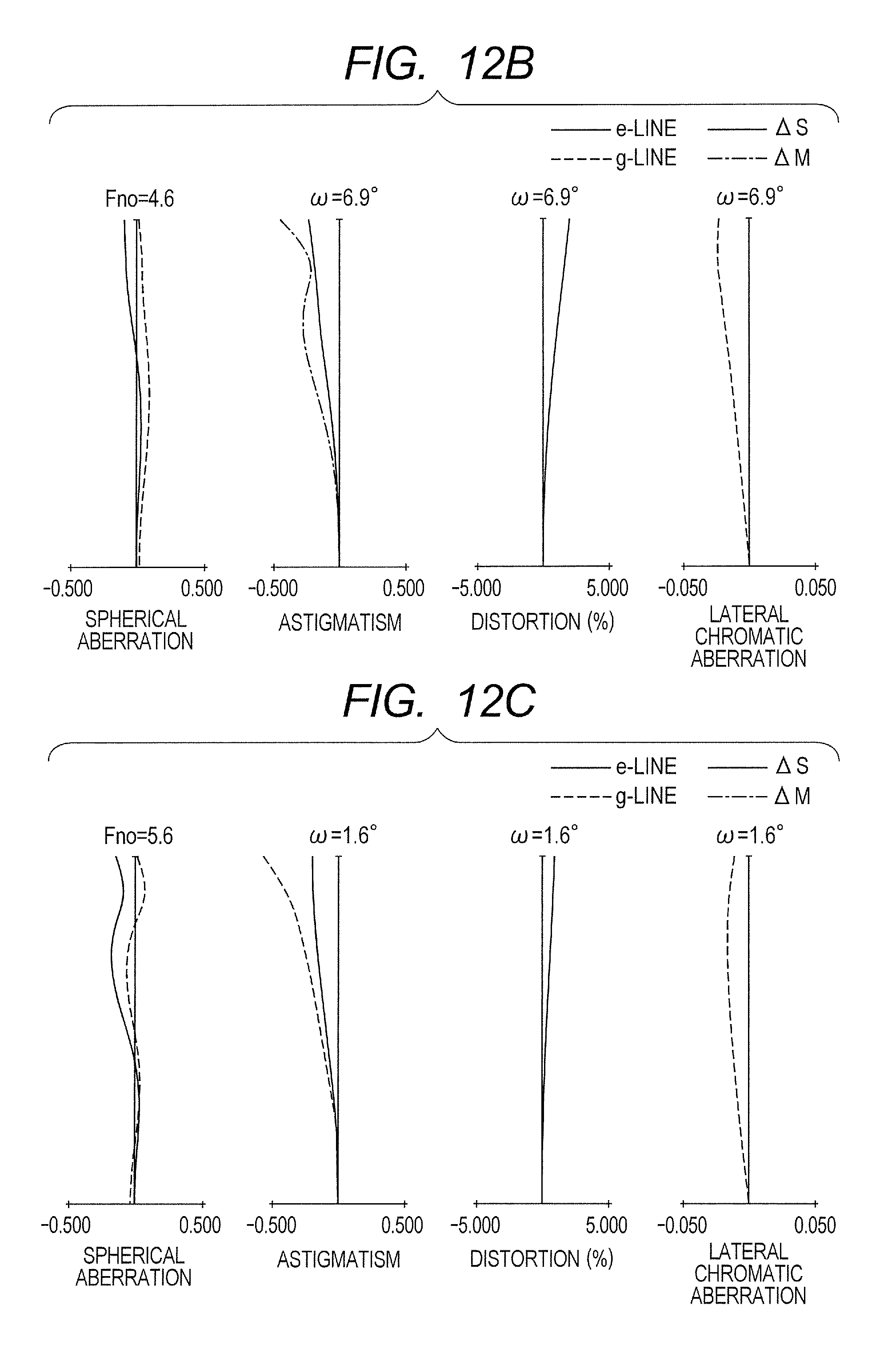
D00013
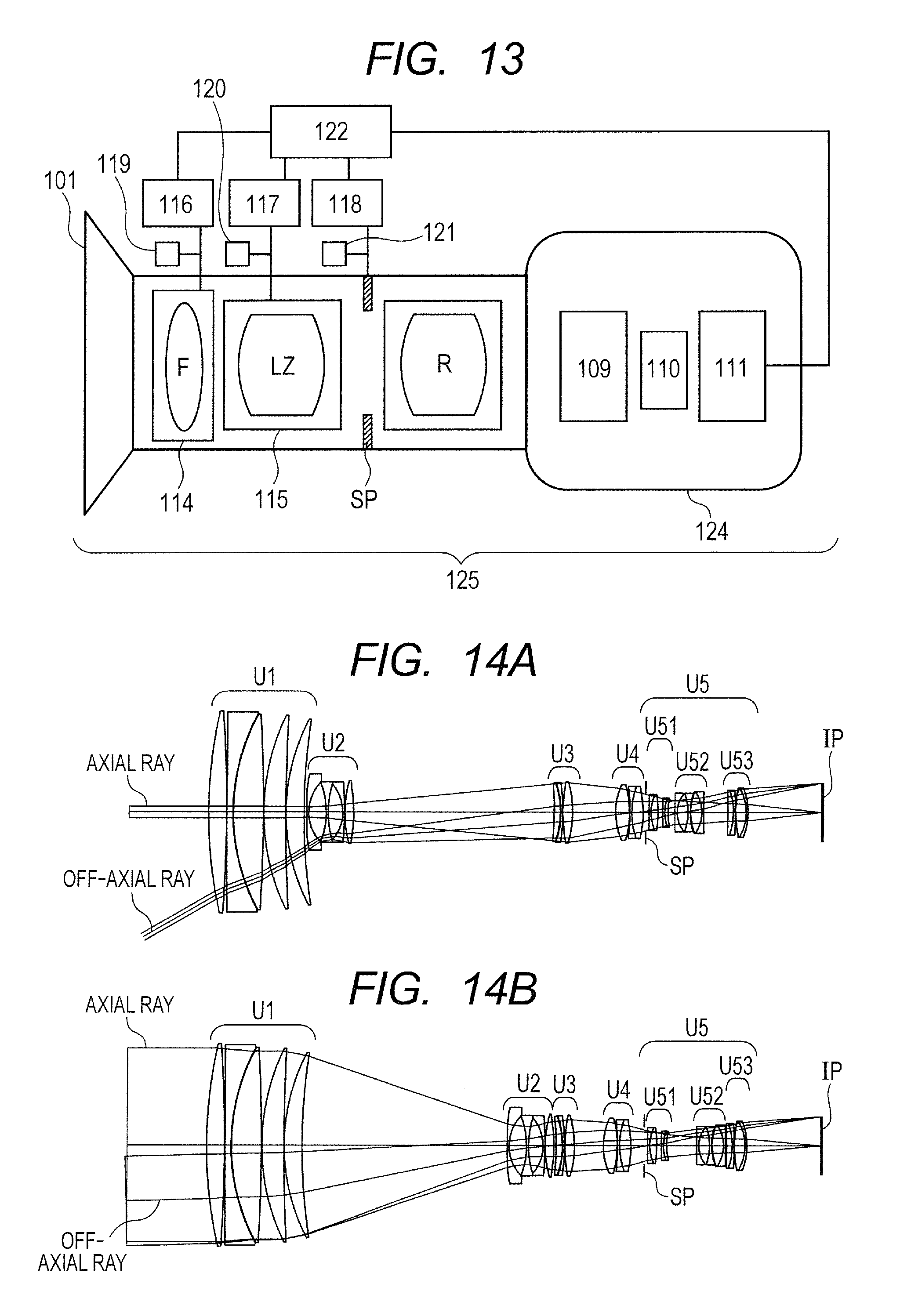
M00001
XML
uspto.report is an independent third-party trademark research tool that is not affiliated, endorsed, or sponsored by the United States Patent and Trademark Office (USPTO) or any other governmental organization. The information provided by uspto.report is based on publicly available data at the time of writing and is intended for informational purposes only.
While we strive to provide accurate and up-to-date information, we do not guarantee the accuracy, completeness, reliability, or suitability of the information displayed on this site. The use of this site is at your own risk. Any reliance you place on such information is therefore strictly at your own risk.
All official trademark data, including owner information, should be verified by visiting the official USPTO website at www.uspto.gov. This site is not intended to replace professional legal advice and should not be used as a substitute for consulting with a legal professional who is knowledgeable about trademark law.