Marker delivery device for tissue marker placement
Ranpura , et al.
U.S. patent number 10,258,428 [Application Number 14/202,842] was granted by the patent office on 2019-04-16 for marker delivery device for tissue marker placement. This patent grant is currently assigned to C. R. Bard, Inc.. The grantee listed for this patent is C. R. Bard, Inc.. Invention is credited to Himanshu Ranpura, Chad C. Van Liere.


View All Diagrams
| United States Patent | 10,258,428 |
| Ranpura , et al. | April 16, 2019 |
Marker delivery device for tissue marker placement
Abstract
A marker delivery device is configured for deploying a tissue marker. The marker delivery device includes a handle having a chamber, and a cannula. According to one aspect, the cannula has a flexible portion formed by a slot arrangement having of a plurality of spaced-apart substantially parallel peripheral slots extending through the side wall of the cannula to the lumen. A marker introducer rod is movably disposed in the lumen of the cannula for deploying the mark, and has a flexible region that corresponds to the flexible portion of the cannula. According to another aspect, a retraction mechanism is mounted to the handle and is configured to facilitate a complete retraction of both the cannula and the marker introducer rod into the chamber of the housing of the handle upon an actuation of the retraction mechanism.
| Inventors: | Ranpura; Himanshu (Stevenson Ranch, CA), Van Liere; Chad C. (Phoenix, AZ) | ||||||||||
|---|---|---|---|---|---|---|---|---|---|---|---|
| Applicant: |
|
||||||||||
| Assignee: | C. R. Bard, Inc. (Franklin
Lakes, NJ) |
||||||||||
| Family ID: | 42310031 | ||||||||||
| Appl. No.: | 14/202,842 | ||||||||||
| Filed: | March 10, 2014 |
Prior Publication Data
| Document Identifier | Publication Date | |
|---|---|---|
| US 20140194892 A1 | Jul 10, 2014 | |
Related U.S. Patent Documents
| Application Number | Filing Date | Patent Number | Issue Date | ||
|---|---|---|---|---|---|
| 12595010 | 8670818 | ||||
| PCT/US2008/088558 | Dec 30, 2008 | ||||
| Current U.S. Class: | 1/1 |
| Current CPC Class: | A61B 90/39 (20160201); A61B 2090/3987 (20160201) |
| Current International Class: | A61B 5/05 (20060101); A61B 6/00 (20060101); A61B 90/00 (20160101) |
References Cited [Referenced By]
U.S. Patent Documents
| 2481408 | September 1949 | Fuller et al. |
| 2899362 | August 1959 | Sieger, Jr. et al. |
| 2907327 | October 1959 | White |
| 3005457 | October 1961 | Millman |
| 3128744 | April 1964 | Jefferts et al. |
| 3341417 | September 1967 | Sinaiko |
| 3402712 | September 1968 | Eisenhand |
| 3516412 | June 1970 | Ackerman |
| 3593343 | July 1971 | Viggers |
| 3757781 | September 1973 | Smart |
| 3818894 | June 1974 | Wichterle et al. |
| 3820545 | June 1974 | Jefferts |
| 3823212 | July 1974 | Chvapil |
| 3921632 | November 1975 | Bardani |
| 4005699 | February 1977 | Bucalo |
| 4007732 | February 1977 | Kvavle et al. |
| 4041931 | August 1977 | Elliott et al. |
| 4086914 | May 1978 | Moore |
| 4103690 | August 1978 | Harris |
| 4105030 | August 1978 | Kercso |
| 4127774 | November 1978 | Gillen |
| 4172449 | October 1979 | LeRoy et al. |
| 4197846 | April 1980 | Bucalo |
| 4217889 | August 1980 | Radovan et al. |
| 4276885 | July 1981 | Tickner et al. |
| 4294241 | October 1981 | Miyata |
| 4298998 | November 1981 | Naficy |
| 4331654 | May 1982 | Morris |
| 4347234 | August 1982 | Wahlig et al. |
| 4390018 | June 1983 | Zukowski |
| 4400170 | August 1983 | McNaughton et al. |
| 4401124 | August 1983 | Guess et al. |
| 4405314 | September 1983 | Cope |
| 4428082 | January 1984 | Naficy |
| 4438253 | March 1984 | Casey et al. |
| 4442843 | April 1984 | Rasor et al. |
| 4470160 | September 1984 | Cavon |
| 4487209 | December 1984 | Mehl |
| 4545367 | October 1985 | Tucci |
| 4549560 | October 1985 | Andis |
| 4582061 | April 1986 | Fry |
| 4582640 | April 1986 | Smestad et al. |
| 4588395 | May 1986 | Lemelson |
| 4597753 | July 1986 | Turley |
| 4647480 | March 1987 | Ahmed |
| 4655226 | April 1987 | Lee |
| 4661103 | April 1987 | Harman |
| 4682606 | July 1987 | DeCaprio |
| 4693237 | September 1987 | Hoffman et al. |
| 4718433 | January 1988 | Feinstein |
| 4740208 | April 1988 | Cavon |
| 4762128 | August 1988 | Rosenbluth |
| 4813062 | March 1989 | Gilpatrick |
| 4820267 | April 1989 | Harman |
| 4832680 | May 1989 | Haber et al. |
| 4832686 | May 1989 | Anderson |
| 4847049 | July 1989 | Yamamoto |
| 4863470 | September 1989 | Carter |
| 4870966 | October 1989 | Dellon et al. |
| 4874376 | October 1989 | Hawkins, Jr. |
| 4889707 | December 1989 | Day et al. |
| 4909250 | March 1990 | Smith |
| 4931059 | June 1990 | Markham |
| 4938763 | July 1990 | Dunn et al. |
| 4950234 | August 1990 | Fujioka et al. |
| 4950665 | August 1990 | Floyd |
| 4963150 | October 1990 | Brauman |
| 4970298 | November 1990 | Silver et al. |
| 4989608 | February 1991 | Ratner |
| 4994013 | February 1991 | Suthanthiran et al. |
| 4994028 | February 1991 | Leonard et al. |
| 5012818 | May 1991 | Joishy |
| 5013090 | May 1991 | Matsuura |
| 5018530 | May 1991 | Rank et al. |
| 5035891 | July 1991 | Runkel et al. |
| 5059197 | October 1991 | Urie et al. |
| 5081997 | January 1992 | Bosley, Jr. et al. |
| 5108421 | April 1992 | Fowler |
| 5120802 | June 1992 | Mares et al. |
| 5125413 | June 1992 | Baran |
| 5137928 | August 1992 | Erbel et al. |
| 5141748 | August 1992 | Rizzo |
| 5147295 | September 1992 | Stewart |
| 5147307 | September 1992 | Gluck |
| 5147631 | September 1992 | Glajch et al. |
| 5162430 | November 1992 | Rhee et al. |
| 5163896 | November 1992 | Suthanthiran et al. |
| 5195540 | March 1993 | Shiber |
| 5197482 | March 1993 | Rank et al. |
| 5197846 | March 1993 | Uno et al. |
| 5199441 | April 1993 | Hogle |
| 5201704 | April 1993 | Ray |
| 5219339 | June 1993 | Saito |
| 5221269 | June 1993 | Miller et al. |
| 5231615 | July 1993 | Endoh |
| 5234426 | August 1993 | Rank et al. |
| 5236410 | August 1993 | Granov et al. |
| 5242759 | September 1993 | Hall |
| 5250026 | October 1993 | Ehrlich et al. |
| 5271961 | December 1993 | Mathiowitz et al. |
| 5273532 | December 1993 | Niezink et al. |
| 5280788 | January 1994 | Janes et al. |
| 5281197 | January 1994 | Arias et al. |
| 5281408 | January 1994 | Unger |
| 5282781 | February 1994 | Liprie |
| 5284479 | February 1994 | de Jong |
| 5289831 | March 1994 | Bosley |
| 5290310 | March 1994 | Makower et al. |
| 5312435 | May 1994 | Nash et al. |
| 5320100 | June 1994 | Herweck et al. |
| 5320613 | June 1994 | Houge et al. |
| 5328955 | July 1994 | Rhee et al. |
| 5334216 | August 1994 | Vidal et al. |
| 5334381 | August 1994 | Unger |
| 5344640 | September 1994 | Deutsch et al. |
| 5353804 | October 1994 | Kornberg et al. |
| 5354623 | October 1994 | Hall |
| 5358514 | October 1994 | Schulman et al. |
| 5360416 | November 1994 | Ausherman et al. |
| 5366756 | November 1994 | Chesterfield et al. |
| 5368030 | November 1994 | Zinreich et al. |
| 5388588 | February 1995 | Nabai et al. |
| 5394875 | March 1995 | Lewis et al. |
| 5395319 | March 1995 | Hirsch et al. |
| 5405402 | April 1995 | Dye et al. |
| 5409004 | April 1995 | Sloan |
| 5417708 | May 1995 | Hall et al. |
| 5422730 | June 1995 | Barlow et al. |
| 5425366 | June 1995 | Reinhardt et al. |
| 5431639 | July 1995 | Shaw |
| 5433204 | July 1995 | Olson |
| 5449560 | September 1995 | Antheunis et al. |
| 5451406 | September 1995 | Lawin et al. |
| 5458643 | October 1995 | Oka et al. |
| 5460182 | October 1995 | Goodman et al. |
| 5469847 | November 1995 | Zinreich et al. |
| 5475052 | December 1995 | Rhee et al. |
| 5490521 | February 1996 | Davis et al. |
| 5494030 | February 1996 | Swartz et al. |
| 5499989 | March 1996 | LaBash |
| 5507807 | April 1996 | Shippert |
| 5508021 | April 1996 | Grinstaff et al. |
| 5514085 | May 1996 | Yoon |
| 5522896 | June 1996 | Prescott |
| 5538726 | July 1996 | Order |
| 5542915 | August 1996 | Edwards et al. |
| 5545180 | August 1996 | Le et al. |
| 5549560 | August 1996 | Van de Wijdeven |
| 5567413 | October 1996 | Klaveness et al. |
| RE35391 | December 1996 | Brauman |
| 5580568 | December 1996 | Greff et al. |
| 5585112 | December 1996 | Unger et al. |
| 5611352 | March 1997 | Kobren et al. |
| 5626611 | May 1997 | Liu et al. |
| 5628781 | May 1997 | Williams et al. |
| 5629008 | May 1997 | Lee |
| 5636255 | June 1997 | Ellis |
| 5643246 | July 1997 | Leeb et al. |
| 5646146 | July 1997 | Faarup et al. |
| 5657366 | August 1997 | Nakayama |
| 5665092 | September 1997 | Mangiardi et al. |
| 5667767 | September 1997 | Greff et al. |
| 5669882 | September 1997 | Pyles |
| 5673841 | October 1997 | Schulze et al. |
| 5676146 | October 1997 | Scarborough |
| 5676925 | October 1997 | Klaveness et al. |
| 5688490 | November 1997 | Tournier et al. |
| 5690120 | November 1997 | Jacobsen et al. |
| 5695480 | December 1997 | Evans et al. |
| 5702128 | December 1997 | Maxim et al. |
| 5702682 | December 1997 | Thompson |
| 5702716 | December 1997 | Dunn et al. |
| 5716981 | February 1998 | Hunter et al. |
| 5747060 | May 1998 | Sackler et al. |
| 5749887 | May 1998 | Heske et al. |
| 5752974 | May 1998 | Rhee et al. |
| 5762903 | June 1998 | Park et al. |
| 5769086 | June 1998 | Ritchart et al. |
| 5776496 | July 1998 | Violante et al. |
| 5779647 | July 1998 | Chau et al. |
| 5782764 | July 1998 | Werne |
| 5782771 | July 1998 | Hussman |
| 5782775 | July 1998 | Milliman et al. |
| 5795308 | August 1998 | Russin |
| 5799099 | August 1998 | Wang et al. |
| 5800362 | September 1998 | Kobren et al. |
| 5800389 | September 1998 | Burney et al. |
| 5800445 | September 1998 | Ratcliff et al. |
| 5800541 | September 1998 | Rhee et al. |
| 5810884 | September 1998 | Kim |
| 5817022 | October 1998 | Vesely |
| 5820918 | October 1998 | Ronan et al. |
| 5821184 | October 1998 | Haines et al. |
| 5823198 | October 1998 | Jones et al. |
| 5824042 | October 1998 | Lombardi et al. |
| 5824081 | October 1998 | Knapp et al. |
| 5826776 | October 1998 | Schulze et al. |
| 5830178 | November 1998 | Jones et al. |
| 5830222 | November 1998 | Makower |
| 5842477 | December 1998 | Naughton et al. |
| 5842999 | December 1998 | Pruitt et al. |
| 5845646 | December 1998 | Lemelson |
| 5846220 | December 1998 | Elsberry |
| 5851508 | December 1998 | Greff et al. |
| 5853366 | December 1998 | Dowlatshahi |
| 5865806 | February 1999 | Howell |
| 5869080 | February 1999 | McGregor et al. |
| 5871501 | February 1999 | Leschinsky et al. |
| 5876340 | March 1999 | Tu et al. |
| 5879357 | March 1999 | Heaton et al. |
| 5891558 | April 1999 | Bell et al. |
| 5897507 | April 1999 | Kortenbach et al. |
| 5902310 | May 1999 | Foerster et al. |
| 5911705 | June 1999 | Howell |
| 5916164 | June 1999 | Fitzpatrick et al. |
| 5921933 | July 1999 | Sarkis et al. |
| 5922024 | July 1999 | Janzen et al. |
| 5928626 | July 1999 | Klaveness et al. |
| 5928773 | July 1999 | Andersen |
| 5941439 | August 1999 | Kammerer et al. |
| 5941890 | August 1999 | Voegele et al. |
| 5942209 | August 1999 | Leavitt et al. |
| 5948425 | September 1999 | Janzen et al. |
| 5954670 | September 1999 | Baker |
| 5972817 | October 1999 | Haines et al. |
| 5976146 | November 1999 | Ogawa et al. |
| 5980564 | November 1999 | Stinson |
| 5989265 | November 1999 | Bouquet De La Joliniere et al. |
| 6015541 | January 2000 | Greff et al. |
| 6030333 | February 2000 | Sioshansi et al. |
| 6053925 | April 2000 | Barnhart |
| 6056700 | May 2000 | Burney et al. |
| 6066122 | May 2000 | Fisher |
| 6066325 | May 2000 | Wallace et al. |
| 6071301 | June 2000 | Cragg et al. |
| 6071310 | June 2000 | Picha et al. |
| 6071496 | June 2000 | Stein et al. |
| 6090996 | July 2000 | Li |
| 6096065 | August 2000 | Crowley |
| 6096070 | August 2000 | Ragheb et al. |
| 6106473 | August 2000 | Violante et al. |
| 6117108 | September 2000 | Woehr et al. |
| 6120536 | September 2000 | Ding et al. |
| 6135993 | October 2000 | Hussman |
| 6142955 | November 2000 | Farascioni et al. |
| 6159240 | December 2000 | Sparer et al. |
| 6159445 | December 2000 | Klaveness et al. |
| 6161034 | December 2000 | Burbank et al. |
| 6162192 | December 2000 | Cragg et al. |
| 6166079 | December 2000 | Follen et al. |
| 6173715 | January 2001 | Sinanan et al. |
| 6174330 | January 2001 | Stinson |
| 6177062 | January 2001 | Stein et al. |
| 6181960 | January 2001 | Jensen et al. |
| 6183497 | February 2001 | Sing et al. |
| 6190350 | February 2001 | Davis et al. |
| 6190353 | February 2001 | Makower et al. |
| 6200258 | March 2001 | Slater et al. |
| 6203507 | March 2001 | Wadsworth et al. |
| 6203524 | March 2001 | Burney et al. |
| 6203568 | March 2001 | Lombardi et al. |
| 6213957 | April 2001 | Milliman et al. |
| 6214045 | April 2001 | Corbitt, Jr. et al. |
| 6214315 | April 2001 | Greff et al. |
| 6220248 | April 2001 | Voegele et al. |
| 6224630 | May 2001 | Bao et al. |
| 6228049 | May 2001 | Schroeder et al. |
| 6228055 | May 2001 | Foerster et al. |
| 6231615 | May 2001 | Preissman |
| 6234177 | May 2001 | Barsch |
| 6241687 | June 2001 | Voegele et al. |
| 6241734 | June 2001 | Scribner et al. |
| 6251135 | June 2001 | Stinson et al. |
| 6251418 | June 2001 | Ahem et al. |
| 6261243 | July 2001 | Burney et al. |
| 6261302 | July 2001 | Voegele et al. |
| 6264917 | July 2001 | Klaveness et al. |
| 6270464 | August 2001 | Fulton, III et al. |
| 6270472 | August 2001 | Antaki et al. |
| 6287278 | September 2001 | Woehr et al. |
| 6287332 | September 2001 | Bolz et al. |
| 6289229 | September 2001 | Crowley |
| 6306154 | October 2001 | Hudson et al. |
| 6312429 | November 2001 | Burbank et al. |
| 6316522 | November 2001 | Loomis et al. |
| 6325789 | December 2001 | Janzen et al. |
| 6335029 | January 2002 | Kamath et al. |
| 6336904 | January 2002 | Nikolchev |
| 6340367 | January 2002 | Stinson et al. |
| 6343227 | January 2002 | Crowley |
| 6347240 | February 2002 | Foley et al. |
| 6347241 | February 2002 | Burbank et al. |
| 6350244 | February 2002 | Fisher |
| 6350274 | February 2002 | Li |
| 6354989 | March 2002 | Nudeshima |
| 6356112 | March 2002 | Tran et al. |
| 6356782 | March 2002 | Sirimanne et al. |
| 6358217 | March 2002 | Bourassa |
| 6363940 | April 2002 | Krag |
| 6371904 | April 2002 | Sirimanne et al. |
| 6394965 | May 2002 | Klein |
| 6403758 | June 2002 | Loomis |
| 6405733 | June 2002 | Fogarty et al. |
| 6409742 | June 2002 | Fulton, III et al. |
| 6419621 | July 2002 | Sioshansi et al. |
| 6424857 | July 2002 | Henrichs et al. |
| 6425903 | July 2002 | Voegele |
| 6427081 | July 2002 | Burbank et al. |
| 6436030 | August 2002 | Rehil |
| 6447524 | September 2002 | Knodel et al. |
| 6447527 | September 2002 | Thompson et al. |
| 6450937 | September 2002 | Mercereau et al. |
| 6450938 | September 2002 | Miller |
| 6471700 | October 2002 | Burbank et al. |
| 6478790 | November 2002 | Bardani |
| 6506156 | January 2003 | Jones et al. |
| 6511468 | January 2003 | Cragg et al. |
| 6537193 | March 2003 | Lennox |
| 6540981 | April 2003 | Klaveness et al. |
| 6544185 | April 2003 | Montegrande |
| 6544231 | April 2003 | Palmer et al. |
| 6544269 | April 2003 | Osborne et al. |
| 6551253 | April 2003 | Worm et al. |
| 6554760 | April 2003 | Lamoureux et al. |
| 6562317 | May 2003 | Greff et al. |
| 6564806 | May 2003 | Fogarty et al. |
| 6565551 | May 2003 | Jones et al. |
| 6567689 | May 2003 | Burbank et al. |
| 6575888 | June 2003 | Zamora et al. |
| 6575991 | June 2003 | Chesbrough et al. |
| 6585773 | July 2003 | Xie |
| 6605047 | August 2003 | Zarins et al. |
| 6610026 | August 2003 | Cragg et al. |
| 6613002 | September 2003 | Clark et al. |
| 6616630 | September 2003 | Woehr et al. |
| 6626850 | September 2003 | Chau et al. |
| 6626899 | September 2003 | Houser et al. |
| 6628982 | September 2003 | Thomas et al. |
| 6629947 | October 2003 | Sahatjian et al. |
| 6636758 | October 2003 | Sanchez et al. |
| 6638234 | October 2003 | Burbank et al. |
| 6638308 | October 2003 | Corbitt, Jr. et al. |
| 6652442 | November 2003 | Gatto |
| 6656192 | December 2003 | Espositio et al. |
| 6659933 | December 2003 | Asano |
| 6662041 | December 2003 | Burbank et al. |
| 6699205 | March 2004 | Fulton, III et al. |
| 6712774 | March 2004 | Voegele et al. |
| 6712836 | March 2004 | Berg et al. |
| 6716444 | April 2004 | Castro et al. |
| 6725083 | April 2004 | Burbank et al. |
| 6730042 | May 2004 | Fulton et al. |
| 6730044 | May 2004 | Stephens et al. |
| 6746661 | June 2004 | Kaplan |
| 6746773 | June 2004 | Llanos et al. |
| 6752154 | June 2004 | Fogarty et al. |
| 6766186 | July 2004 | Hoyns et al. |
| 6774278 | August 2004 | Ragheb et al. |
| 6780179 | August 2004 | Lee et al. |
| 6824507 | November 2004 | Miller |
| 6824527 | November 2004 | Gollobin |
| 6846320 | January 2005 | Ashby et al. |
| 6862470 | March 2005 | Burbank et al. |
| 6863685 | March 2005 | Davila et al. |
| 6881226 | April 2005 | Corbitt, Jr. et al. |
| 6889833 | May 2005 | Seiler et al. |
| 6899731 | May 2005 | Li et al. |
| 6918927 | July 2005 | Bates et al. |
| 6936014 | August 2005 | Vetter et al. |
| 6939318 | September 2005 | Stenzel |
| 6945973 | September 2005 | Bray |
| 6951564 | October 2005 | Espositio et al. |
| 6958044 | October 2005 | Burbank et al. |
| 6992233 | January 2006 | Drake et al. |
| 6993375 | January 2006 | Burbank et al. |
| 6994712 | February 2006 | Fisher et al. |
| 6996433 | February 2006 | Burbank et al. |
| 7001341 | February 2006 | Gellman et al. |
| 7008382 | March 2006 | Adams et al. |
| 7014610 | March 2006 | Koulik |
| 7025765 | April 2006 | Balbierz et al. |
| 7041047 | May 2006 | Gellman et al. |
| 7044957 | May 2006 | Foerster et al. |
| 7047063 | May 2006 | Burbank et al. |
| 7083576 | August 2006 | Zarins et al. |
| 7125397 | October 2006 | Woehr et al. |
| 7135978 | November 2006 | Gisselberg et al. |
| 7160258 | January 2007 | Imran et al. |
| 7172549 | February 2007 | Slater et al. |
| 7189206 | March 2007 | Quick et al. |
| 7214211 | May 2007 | Woehr et al. |
| 7229417 | June 2007 | Foerster et al. |
| 7236816 | June 2007 | Kumar et al. |
| 7264613 | September 2007 | Woehr et al. |
| 7280865 | October 2007 | Adler |
| 7294118 | November 2007 | Saulenas et al. |
| 7297725 | November 2007 | Winterton et al. |
| 7329402 | February 2008 | Unger et al. |
| 7329414 | February 2008 | Fisher et al. |
| 7407054 | August 2008 | Seiler et al. |
| 7416533 | August 2008 | Gellman et al. |
| 7424320 | September 2008 | Chesbrough et al. |
| 7449000 | November 2008 | Adams et al. |
| 7527610 | May 2009 | Erickson |
| 7534452 | May 2009 | Chernomorsky et al. |
| 7535363 | May 2009 | Gisselberg et al. |
| 7565191 | July 2009 | Burbank et al. |
| 7569065 | August 2009 | Chesbrough et al. |
| 7577473 | August 2009 | Davis et al. |
| 7637948 | December 2009 | Corbitt, Jr. |
| 7651505 | January 2010 | Lubock et al. |
| 7668582 | February 2010 | Sirimanne et al. |
| 7670350 | March 2010 | Sells |
| 7783336 | August 2010 | Macfarlane et al. |
| 7792569 | September 2010 | Burbank et al. |
| 7819819 | October 2010 | Quick et al. |
| 7819820 | October 2010 | Field et al. |
| 7844319 | November 2010 | Susil et al. |
| 7871438 | January 2011 | Corbitt, Jr. |
| 7877133 | January 2011 | Burbank et al. |
| 7914553 | March 2011 | Ferree |
| 7945307 | May 2011 | Lubock et al. |
| 7978825 | July 2011 | Ngo |
| 7983734 | July 2011 | Jones et al. |
| 8011508 | September 2011 | Seiler et al. |
| 8027712 | September 2011 | Sioshansi et al. |
| 8052658 | November 2011 | Field |
| 8052708 | November 2011 | Chesbrough et al. |
| 8064987 | November 2011 | Carr, Jr. |
| 8128641 | March 2012 | Wardle |
| 8157862 | April 2012 | Corbitt, Jr. |
| 8306602 | November 2012 | Sirimanne et al. |
| 8311610 | November 2012 | Ranpura |
| 8320993 | November 2012 | Sirimanne et al. |
| 8320994 | November 2012 | Sirimanne et al. |
| 8320995 | November 2012 | Schwamb, Jr. |
| 8334424 | December 2012 | Szypka |
| 8361082 | January 2013 | Jones et al. |
| 8401622 | March 2013 | Talpade et al. |
| 8437834 | May 2013 | Carr, Jr. |
| 8442623 | May 2013 | Nicoson et al. |
| 8454629 | June 2013 | Selis |
| 8486028 | July 2013 | Field |
| 8579931 | November 2013 | Chesbrough et al. |
| 8626269 | January 2014 | Jones et al. |
| 8626270 | January 2014 | Burbank et al. |
| 8639315 | January 2014 | Burbank et al. |
| 8668737 | March 2014 | Corbitt, Jr. |
| 8680498 | March 2014 | Corbitt et al. |
| 9237937 | January 2016 | Burbank et al. |
| 2001/0006616 | July 2001 | Leavitt et al. |
| 2002/0004060 | January 2002 | Heublein et al. |
| 2002/0016625 | February 2002 | Falotico et al. |
| 2002/0022883 | February 2002 | Burg |
| 2002/0026201 | February 2002 | Foerster et al. |
| 2002/0035324 | March 2002 | Sirimanne et al. |
| 2002/0044969 | April 2002 | Harden et al. |
| 2002/0045842 | April 2002 | Van Bladel et al. |
| 2002/0052572 | May 2002 | Franco et al. |
| 2002/0055731 | May 2002 | Atala et al. |
| 2002/0058868 | May 2002 | Hoshino et al. |
| 2002/0058882 | May 2002 | Fulton, III et al. |
| 2002/0077687 | June 2002 | Ahn |
| 2002/0082517 | June 2002 | Klein |
| 2002/0082519 | June 2002 | Miller et al. |
| 2002/0082682 | June 2002 | Barclay et al. |
| 2002/0082683 | June 2002 | Stinson et al. |
| 2002/0095204 | July 2002 | Thompson et al. |
| 2002/0095205 | July 2002 | Edwin et al. |
| 2002/0107437 | August 2002 | Sirimanne et al. |
| 2002/0133148 | September 2002 | Daniel et al. |
| 2002/0143359 | October 2002 | Fulton, III et al. |
| 2002/0165608 | November 2002 | Llanos et al. |
| 2002/0177776 | November 2002 | Crawford Kellar et al. |
| 2002/0193815 | December 2002 | Foerster et al. |
| 2002/0193867 | December 2002 | Gladdish, Jr. et al. |
| 2003/0032969 | February 2003 | Gannoe et al. |
| 2003/0036803 | February 2003 | McGhan |
| 2003/0051735 | March 2003 | Pavcnik et al. |
| 2003/0116806 | June 2003 | Kato |
| 2003/0165478 | September 2003 | Sokoll |
| 2003/0191355 | October 2003 | Ferguson |
| 2003/0199887 | October 2003 | Ferrera et al. |
| 2003/0225420 | December 2003 | Wardle |
| 2003/0233101 | December 2003 | Lubock et al. |
| 2003/0236573 | December 2003 | Evans et al. |
| 2004/0001841 | January 2004 | Nagavarapu et al. |
| 2004/0002650 | January 2004 | Mandrusov et al. |
| 2004/0016195 | January 2004 | Archuleta |
| 2004/0024304 | February 2004 | Foerster et al. |
| 2004/0059341 | March 2004 | Gellman et al. |
| 2004/0068312 | April 2004 | Sigg et al. |
| 2004/0073107 | April 2004 | Sioshansi et al. |
| 2004/0073284 | April 2004 | Bates et al. |
| 2004/0097981 | May 2004 | Selis |
| 2004/0101479 | May 2004 | Burbank et al. |
| 2004/0101548 | May 2004 | Pendharkar |
| 2004/0106891 | June 2004 | Langan et al. |
| 2004/0116802 | June 2004 | Jessop et al. |
| 2004/0124105 | July 2004 | Seiler et al. |
| 2004/0127765 | July 2004 | Seiler et al. |
| 2004/0133124 | July 2004 | Bates et al. |
| 2004/0153074 | August 2004 | Bojarski et al. |
| 2004/0162574 | August 2004 | Viola |
| 2004/0167619 | August 2004 | Case et al. |
| 2004/0204660 | October 2004 | Fulton et al. |
| 2004/0210208 | October 2004 | Paul et al. |
| 2004/0213756 | October 2004 | Michal et al. |
| 2004/0236212 | November 2004 | Jones et al. |
| 2004/0236213 | November 2004 | Jones et al. |
| 2004/0253185 | December 2004 | Herweck et al. |
| 2004/0265371 | December 2004 | Looney et al. |
| 2005/0020916 | January 2005 | MacFarlane et al. |
| 2005/0033157 | February 2005 | Klien et al. |
| 2005/0033195 | February 2005 | Fulton et al. |
| 2005/0036946 | February 2005 | Pathak et al. |
| 2005/0038355 | February 2005 | Gellman et al. |
| 2005/0045192 | March 2005 | Fulton et al. |
| 2005/0059887 | March 2005 | Mostafavi et al. |
| 2005/0059888 | March 2005 | Sirimanne et al. |
| 2005/0065354 | March 2005 | Roberts |
| 2005/0065453 | March 2005 | Shabaz et al. |
| 2005/0080337 | April 2005 | Sirimanne et al. |
| 2005/0080339 | April 2005 | Sirimanne et al. |
| 2005/0085724 | April 2005 | Sirimanne et al. |
| 2005/0100580 | May 2005 | Osborne et al. |
| 2005/0112151 | May 2005 | Horng |
| 2005/0113659 | May 2005 | Pothier et al. |
| 2005/0119562 | June 2005 | Jones et al. |
| 2005/0142161 | June 2005 | Freeman et al. |
| 2005/0143650 | June 2005 | Winkel |
| 2005/0165305 | July 2005 | Foerster et al. |
| 2005/0175657 | August 2005 | Hunter et al. |
| 2005/0181007 | August 2005 | Hunter et al. |
| 2005/0208122 | September 2005 | Allen et al. |
| 2005/0216018 | September 2005 | Sennett |
| 2005/0234336 | October 2005 | Beckman et al. |
| 2005/0268922 | December 2005 | Conrad et al. |
| 2005/0273002 | December 2005 | Goosen et al. |
| 2005/0277871 | December 2005 | Selis |
| 2006/0004440 | January 2006 | Stinson |
| 2006/0009800 | January 2006 | Christianson et al. |
| 2006/0025677 | February 2006 | Verard et al. |
| 2006/0025795 | February 2006 | Chesbrough et al. |
| 2006/0036158 | February 2006 | Field et al. |
| 2006/0036159 | February 2006 | Sirimanne et al. |
| 2006/0074443 | April 2006 | Foerster et al. |
| 2006/0079770 | April 2006 | Sirimanne et al. |
| 2006/0079805 | April 2006 | Miller et al. |
| 2006/0079829 | April 2006 | Fulton et al. |
| 2006/0079888 | April 2006 | Mulier et al. |
| 2006/0116573 | June 2006 | Field et al. |
| 2006/0122503 | June 2006 | Burbank et al. |
| 2006/0155190 | July 2006 | Burbank et al. |
| 2006/0173280 | August 2006 | Goosen et al. |
| 2006/0173296 | August 2006 | Miller et al. |
| 2006/0177379 | August 2006 | Asgari |
| 2006/0217635 | September 2006 | McCombs et al. |
| 2006/0235298 | October 2006 | Kotmel et al. |
| 2006/0241385 | October 2006 | Dietz |
| 2006/0241411 | October 2006 | Field |
| 2006/0292690 | December 2006 | Liu et al. |
| 2007/0021642 | January 2007 | Lamoureux et al. |
| 2007/0038145 | February 2007 | Field |
| 2007/0057794 | March 2007 | Gisselberg et al. |
| 2007/0083132 | April 2007 | Sharrow |
| 2007/0087026 | April 2007 | Field |
| 2007/0106152 | May 2007 | Kantrowitz et al. |
| 2007/0135711 | June 2007 | Chernomorsky et al. |
| 2007/0142725 | June 2007 | Hardin et al. |
| 2007/0167736 | July 2007 | Dietz et al. |
| 2007/0167749 | July 2007 | Yarnall et al. |
| 2007/0239118 | October 2007 | Ono et al. |
| 2007/0276492 | November 2007 | Andrews et al. |
| 2007/0287933 | December 2007 | Phan et al. |
| 2008/0033280 | February 2008 | Lubock et al. |
| 2008/0039819 | February 2008 | Jones et al. |
| 2008/0058640 | March 2008 | Jones et al. |
| 2008/0091120 | April 2008 | Fisher |
| 2008/0097199 | April 2008 | Mullen |
| 2008/0121242 | May 2008 | Revie et al. |
| 2008/0188768 | August 2008 | Zarins et al. |
| 2008/0249436 | October 2008 | Darr |
| 2008/0269638 | October 2008 | Cooke et al. |
| 2008/0294039 | November 2008 | Jones et al. |
| 2009/0000629 | January 2009 | Hornscheidt et al. |
| 2009/0024225 | January 2009 | Stubbs |
| 2009/0030309 | January 2009 | Jones et al. |
| 2009/0069713 | March 2009 | Adams et al. |
| 2009/0076484 | March 2009 | Fukaya |
| 2009/0093714 | April 2009 | Chesbrough et al. |
| 2009/0131825 | May 2009 | Burbank et al. |
| 2009/0171198 | July 2009 | Jones et al. |
| 2009/0216118 | August 2009 | Jones et al. |
| 2009/0287078 | November 2009 | Burbank et al. |
| 2010/0010341 | January 2010 | Talpade et al. |
| 2010/0010342 | January 2010 | Burbank et al. |
| 2010/0030072 | February 2010 | Casanova et al. |
| 2010/0030149 | February 2010 | Carr, Jr. |
| 2010/0042041 | February 2010 | Tune et al. |
| 2010/0082102 | April 2010 | Govil et al. |
| 2010/0094169 | April 2010 | Lubock et al. |
| 2010/0198059 | August 2010 | Burbank et al. |
| 2010/0204570 | August 2010 | Lubock |
| 2010/0298696 | November 2010 | Field et al. |
| 2010/0298698 | November 2010 | Burbank et al. |
| 2010/0324416 | December 2010 | Burbank et al. |
| 2010/0331668 | December 2010 | Ranpura |
| 2011/0092815 | April 2011 | Burbank et al. |
| 2011/0184280 | July 2011 | Jones et al. |
| 2011/0184449 | July 2011 | Lubock et al. |
| 2012/0078092 | March 2012 | Jones et al. |
| 2012/0116215 | May 2012 | Jones et al. |
| 2012/0215230 | August 2012 | Lubock et al. |
| 2012/0277859 | November 2012 | Govil et al. |
| 2013/0144157 | June 2013 | Jones et al. |
| 2013/0184562 | July 2013 | Talpade et al. |
| 2013/0190616 | July 2013 | Casanova et al. |
| 2013/0281847 | October 2013 | Jones et al. |
| 2013/0310686 | November 2013 | Jones et al. |
| 2014/0058258 | February 2014 | Chesbrough et al. |
| 2014/0094698 | April 2014 | Burbank et al. |
| 2014/0114186 | April 2014 | Burbank et al. |
| 2014/0142696 | May 2014 | Corbitt, Jr. |
| 2014/0239528 | August 2014 | Govil et al. |
| 2014/0243675 | August 2014 | Burbank et al. |
| 2015/0051477 | February 2015 | Jones et al. |
| 2015/0164610 | June 2015 | Field et al. |
| 2015/0245883 | September 2015 | Talpade et al. |
| 2016/0015475 | January 2016 | Jones et al. |
| 2016/0120510 | May 2016 | Burbank et al. |
| 2016/0128797 | May 2016 | Burbank et al. |
| 2016/0199150 | July 2016 | Field et al. |
| 2017/0042664 | February 2017 | Corbitt, Jr. |
| 2017/0100203 | April 2017 | Field et al. |
| 2017/0119492 | May 2017 | Chesbrough et al. |
| 2017/0128154 | May 2017 | Casanova et al. |
| 1029528 | May 1958 | DE | |||
| 0146699 | Jul 1985 | EP | |||
| 0255123 | Feb 1988 | EP | |||
| 0292936 | Nov 1988 | EP | |||
| 0458745 | Nov 1991 | EP | |||
| 0475077 | Mar 1992 | EP | |||
| 0552924 | Jul 1993 | EP | |||
| 0769281 | Apr 1997 | EP | |||
| 1114618 | Jul 2001 | EP | |||
| 1163888 | Dec 2001 | EP | |||
| 1281416 | Jun 2002 | EP | |||
| 1364628 | Nov 2003 | EP | |||
| 1493451 | Jan 2005 | EP | |||
| 1767167 | Mar 2007 | EP | |||
| 2646674 | Nov 1990 | FR | |||
| 2853521 | Oct 2004 | FR | |||
| 708148 | Apr 1954 | GB | |||
| 2131757 | May 1990 | JP | |||
| 2006516468 | Jul 2006 | JP | |||
| 2007537017 | Dec 2007 | JP | |||
| 8906978 | Aug 1989 | WO | |||
| 9112823 | Sep 1991 | WO | |||
| 9314712 | Aug 1993 | WO | |||
| 9317671 | Sep 1993 | WO | |||
| 9317718 | Sep 1993 | WO | |||
| 9416647 | Aug 1994 | WO | |||
| 9507057 | Mar 1995 | WO | |||
| 9806346 | Feb 1998 | WO | |||
| 9908607 | Feb 1999 | WO | |||
| 9935966 | Jul 1999 | WO | |||
| 9951143 | Oct 1999 | WO | |||
| 0023124 | Apr 2000 | WO | |||
| 0024332 | May 2000 | WO | |||
| 0028554 | May 2000 | WO | |||
| 0054689 | Sep 2000 | WO | |||
| 0108578 | Feb 2001 | WO | |||
| 0170114 | Sep 2001 | WO | |||
| 0207786 | Jan 2002 | WO | |||
| 0241786 | May 2002 | WO | |||
| 03000308 | Jan 2003 | WO | |||
| 2004045444 | Jun 2004 | WO | |||
| 2005013832 | Feb 2005 | WO | |||
| 2005089664 | Sep 2005 | WO | |||
| 2005112787 | Dec 2005 | WO | |||
| 2006012630 | Feb 2006 | WO | |||
| 2006056739 | Jun 2006 | WO | |||
| 2006097331 | Sep 2006 | WO | |||
| 2006105353 | Oct 2006 | WO | |||
| 2007067255 | Jun 2007 | WO | |||
| 2007069105 | Jun 2007 | WO | |||
| 2008077081 | Jun 2008 | WO | |||
Other References
|
Armstong, J.S., et al., "Differential marking of Excision Planes in Screened Breast lesions by Organically Coloured Gelatins", Journal of Clinical Pathology, Jul. 1990, No. 43 (7) pp. 604-607, XP000971447 abstract; tables 1,2. cited by applicant . Fucci, V., et al., "Large Bowel Transit Times Using Radioopaque Markers in Normal Cats", J. of Am. Animal Hospital Assn., Nov.-Dec. 1995 31 (6) 473-477. cited by applicant . Schindlbeck, N.E., et al., "Measurement of Colon Transit Time", J. of Gastroenterology, No. 28, pp. 399-404, 1990. cited by applicant . Shiga, et al., Preparation of Poly(D, L-lactide) and Copoly(lactide-glycolide) Microspheres of Uniform Size, J. Pharm. Pharmacol. 1996 48:891-895. cited by applicant . Eiselt, P. et al, "Development of Technologies Aiding Large--Tissue Engineering", Biotechnol. Prog., vol. 14, No. 1, pp. 134-140, 1998. cited by applicant . Crook, et al. (Prostate Motion During Standard Radiotherapy As Assessed by Fiducial Markers, 1995, Radiotherapy and Oncology 37:35-42.) cited by applicant . Shah, et al. (Polyethylene Glycol as a Binder for Tablets, vol. 66, No. 11, Nov. 1977, Journal of Pharmaceutical Sciences). cited by applicant . Fajardo, Laurie, et al., "Placement of Endovascular Embolization Microcoils to Localize the Site of Breast Lesions Removed at Stereotactic Core Biopsy", Radiology, Jan. 1998, pp. 275-278, vol. 206--No. 1. cited by applicant . H. J. Gent, M.D., et al., Stereotaxic Needle Localization and Cytological Diagnosis of Occult Breast Lesions, Annals of Surgery, Nov. 1986, pp. 580-584, vol. 204--No. 5. cited by applicant . Meuris, Bart, "Calcification of Aortic Wall Tissue in Prosthetic Heart Valves: Initiation, Influencing Factors and Strategies Towards Prevention", Thesis, 2007, pp. 21-36, Leuven University Press; Leuven, Belgium. cited by applicant . Jong-Won Rhie, et al. "Implantation of Cultured Preadipocyte Using Chitosan/Alginate Sponge", Key Engineering Materials, Jul. 1, 2007, pp. 346-352, XP008159356, ISSN: 0252-1059, DOI: 10.4028/www.scientific.net/KEM.342-343.349, Department of Plastic Surgery, College of Medicine, The Catholic University of Korea, Seoul Korea. cited by applicant . Press release for Biopsys Ethicon Endo-Surgery (Europe) GmbH; The Mammotome Vacuum Biopsy System. From: http://www.medicine-news.com/articles/devices/mammotome.html. 3 pages. cited by applicant . Johnson & Johnson: Breast Biopsy (minimally invasive): Surgical Technique: Steps in the MAMOTOME Surgical Procedure. From http://www.jnjgateway.com. 3 pages. cited by applicant . Johnson & Johnson: New Minimally Invasive Breast Biopsy Device Receives Marketing Clearance in Canada; Aug. 6, 1999. From http://www.jnjgateway.com. 4 pages. cited by applicant . Johnson & Johnson: Mammotome Hand Held Receives FDA Marketing Clearance for Minimally Invasive Breast Biopises; Sep. 1, 1999. From From http://www.jnjgateway.com. 5 pages. cited by applicant . Johnson & Johnson: The Mammotome Breast Biopsy System. From: http://www.breastcareinfo.com/aboutm.htm. 6 pages. cited by applicant . Cook Incorporated: Emoblization and Occlusion. From: www.cookgroup.com 6 pages. cited by applicant . Liberman, Laura, et al. Percutaneous Removal of Malignant Mammographic Lesions at Stereotactic Vacuum-assisted Biopsy. From: The Departments of Radiology, Pathology, and Surgery. Memorial Sloan-Kettering Cancer Center. From the 1997 RSNA scientific assembly. vol. 206, No. 3. pp. 711-715. cited by applicant. |
Primary Examiner: Park; Patricia J
Parent Case Text
This application is a continuation of U.S. patent application Ser. No. 12/595,010, filed Oct. 7, 2009, now U.S. Pat. No. 8,670,818, which is a U.S. national phase of International Application No. PCT/US2008/088558, filed Dec. 30, 2008.
Claims
What is claimed is:
1. A marker delivery device configured for deploying a tissue marker, comprising: a handle including a housing having a front end, a back end, a side wall, a chamber located between the front end and the back end that is surrounded by the side wall, a first hole leading from the chamber to the exterior of the handle through the front end of the housing, and a second hole leading from the chamber to the exterior of the handle through the side wall of the housing; a cannula having a proximal end, a distal end, and a lumen, the cannula being positioned in the handle such that the cannula retractably extends through the first hole beyond the front end of the housing; and a retraction mechanism mounted to the housing, the retraction mechanism being coupled to the proximal end of the cannula, the retraction mechanism being configured to store a retraction force, and configured to facilitate a retraction of the cannula into the chamber of the housing of the handle upon an actuation of the retraction mechanism, the retraction mechanism including: a retraction trigger accessible at the exterior of the housing, the retraction trigger configured to be depressed by an exterior force in an axial direction toward the chamber of the housing of the handle; a shear member having a longitudinal length that is axially oriented relative to the housing of the handle, the longitudinal length having an exterior end and an interior end, the shear member having a shear region of reduced cross section dimension, and the shear region of reduced cross section being located between the exterior end and the interior end; and a cannula guide block attached to the proximal end of the cannula, the retraction force configured to be applied to the cannula guide block, the cannula guide block configured to be slidably disposed in the chamber of the housing, the retraction trigger configured to be linked to the cannula guide block by the shear member via the retraction trigger being coupled to the exterior end of the longitudinal length of the shear member and the cannula guide block being coupled to the interior end of the longitudinal length of the shear member, the retraction mechanism is configured to be in a ready position when the shear region of reduced cross section dimension of the shear member is supported by the side wall by being in alignment with the second hole of the housing of the handle; upon actuation of the retraction trigger, the shear region of reduced cross section dimension is configured to move out of alignment with the second hole and the shear member is configured to be sheared at the shear region of reduced cross section dimension by release of the retraction force upon the cannula guide block which transfers the retraction force to the interior end of the longitudinal length of the shear member to permanently disconnect the retraction trigger from the cannula guide block.
2. The marker delivery device of claim 1, wherein each of the exterior end and the interior end of the longitudinal length of the shear member has the same cross sectional dimension.
3. The marker delivery device of claim 1, wherein the shear region of reduced cross section dimension is an annular groove.
Description
BACKGROUND OF THE INVENTION
1. Field of the Invention
The present invention relates to medical devices, and, more particularly, to a marker delivery device for percutaneous tissue marker placement.
2. Description of the Related Art
Tissue biopsies are commonly performed on many areas and organs of the human body where it is desirable to ascertain whether or not a lesion or other tissue to be biopsied is cancerous. Often, the lesion or other tissue to be biopsied is identified through use of an imaging technique, such as a computerized axial tomography (CAT) scan, ultrasonography, and mammography.
In breast biopsies, for example, the lesion typically is so small that the biopsy reduces its size to the extent that it is no longer visible by the imaging method employed. In such circumstances, it is desirable to place a tissue marker at the site of the biopsy to enable the medical practitioner subsequently to locate the lesion quickly and accurately in the event complete removal of the affected tissue is indicated. The tissue marker is placed at the biopsy site, for example, by a marker delivery device having a needle cannula that houses the tissue marker.
In some marker delivery devices, the marker may not be completely ejected from the cannula, or may be drawn back into or toward the cannula by the vacuum created upon the withdrawal of the cannula, which results in the marker being moved from the intended site, leading to inaccurate identification of the location of the biopsy area. Another issue is the safe disposal of the marker delivery device after use, particularly the safe disposal of the cannula portion of the marker delivery device that is inserted into the tissue of the patient, which typically has a sharp point.
SUMMARY OF THE INVENTION
The invention provides, according to one aspect thereof, a marker delivery device configured to fully deliver the tissue marker at a delivery site in the patient where the tissue marker is less likely to migrate, which is achieved by delivering the tissue marker via a rigid cannula having a flexible portion for directing the distal end of the cannula, for example, into tissue adjacent a biopsy site. The invention provides, according to another aspect thereof, a marker delivery device configured to facilitate the safe disposal of the marker delivery device after use. The marker delivery device may be used, for example, in association with various imaging systems, such as X-ray, ultrasound, MRI etc.
The invention, in one form thereof, is directed to a marker delivery device configured for deploying a tissue marker. The marker delivery device includes a handle having a chamber. A cannula is configured for holding the tissue marker for deployment. The cannula has a side wall surrounding a lumen that extends along a lengthwise extent of the cannula. The cannula has a flexible portion formed by a slot arrangement having of a plurality of peripheral slots extending through the side wall of the cannula to the lumen. The plurality of peripheral slots is spaced apart to be substantially parallel along the lengthwise extent of the cannula to facilitate a flexure at the flexible portion of the cannula. A marker introducer rod is movably disposed in the lumen of the cannula. The marker introducer rod has a flexible region that corresponds to the flexible portion of the cannula. A deployment mechanism is mounted to the handle and configured to displace the marker introducer rod for deploying the tissue marker upon an actuation of the deployment mechanism. A retraction mechanism is mounted to the handle and is configured to facilitate a complete retraction of both the cannula and the marker introducer rod into the chamber of the housing of the handle upon an actuation of the retraction mechanism.
The invention, in another form thereof, is directed to a marker delivery device configured for deploying a tissue marker. The marker delivery device includes a handle configured to be grasped by a user. A cannula has a proximal end and a distal end, the proximal end being coupled to the handle. The cannula is substantially rigid and has a side wall surrounding a lumen that extends along a lengthwise extent of the cannula. The cannula has a flexible portion formed by a slot arrangement having of a plurality of peripheral slots extending through the side wall of the cannula to the lumen. The slots of the plurality of peripheral slots are spaced apart to be substantially parallel along the lengthwise extent of the cannula to facilitate a flexure at the flexible portion of the cannula. A marker introducer rod is movably disposed in the lumen of the cannula to effect a deployment of the tissue marker from the distal end of the cannula. The marker introducer rod has an actuation end and a marker deployment end, and a flexible region that corresponds to the flexible portion of the cannula.
The invention, in another form thereof, is directed to a marker delivery device configured for deploying a tissue marker. The marker delivery device includes a handle configured to be to be grasped by a user. The handle includes a housing having a front end and a back end, with a chamber located between the front end and the back end, and having a hole leading from the chamber to the exterior of the handle. A cannula has a proximal end, a distal end, and a lumen extending along a lengthwise extent of the cannula between the proximal end and the distal end. The cannula is positioned in the handle such that the cannula retractably extends through the hole beyond the front end of the housing. A marker introducer rod is movably disposed in the lumen of the cannula to effect a deployment of the tissue marker from the distal end of the cannula. The marker introducer rod has an actuation end and a marker deployment end. A deployment mechanism is mounted to the housing. The deployment mechanism is coupled to the actuation end of the marker introducer rod. The deployment mechanism is configured to displace the marker introducer rod for deploying the tissue marker upon an actuation of the deployment mechanism. A retraction mechanism is mounted to the housing, and is coupled to the proximal end of the cannula. The retraction mechanism is configured to facilitate a complete retraction of both the cannula and the marker introducer rod into the chamber of the housing of the handle upon an actuation of the retraction mechanism.
BRIEF DESCRIPTION OF THE DRAWINGS
The above-mentioned and other features and advantages of this invention, and the manner of attaining them, will become more apparent and the invention will be better understood by reference to the following description of embodiments of the invention taken in conjunction with the accompanying drawings, wherein:
FIG. 1 is a perspective view of a marker delivery device configured for deploying a tissue marker in accordance with an embodiment of the present invention;
FIG. 2 is a section view of a portion of the marker delivery device of FIG. 1 taken along plane 2-2;
FIG. 3 is a section view of a portion of the marker delivery device of FIG. 1 taken along plane 3-3;
FIG. 4A is a top view of a portion of the cannula of the marker delivery device of FIG. 1 depicting a flexible portion of the cannula;
FIG. 4B is a side view of the flexible portion of the cannula of FIG. 4A, showing in phantom lines the flexure of the flexible portion of the cannula relative to non-flexure;
FIG. 4C is an end view of the cannula of FIG. 4A from the perspective of looking into the lumen of the cannula from the distal end of the cannula, also showing in phantom lines the flexure of the flexible portion of the cannula relative to non-flexure;
FIG. 5 is a top view of an alternative configuration of the flexible portion of the marker delivery device of FIG. 1;
FIG. 6 is a top view of another alternative configuration of the flexible portion of the cannula of the marker delivery device of FIG. 1;
FIG. 7 is a side view of a portion of the marker introducer rod of the marker delivery device of FIG. 1, showing the actuation end, the marker deployment end, and the flexible region;
FIG. 8 is a perspective view of the marker delivery device of FIG. 1 used in conjunction with a biopsy device, showing a flexure of flexible portion of the cannula;
FIG. 9 is a perspective view of the marker delivery device of FIG. 1 following complete retraction of the cannula and marker introducer rod into the longitudinal chamber of the housing of the handle;
FIG. 10 is a perspective view of a marker delivery device configured for deploying a tissue marker in accordance with another embodiment of the present invention;
FIG. 11 is a section view of the marker delivery device of FIG. 10 taken along plane 11-11, showing the deployment mechanism in an initial position;
FIG. 12 is a section view of the marker delivery device of FIG. 10, showing the deployment mechanism in a marker deployed position;
FIG. 13 is a section view of the marker delivery device of FIG. 10, showing the deployment mechanism in a marker introducer rod initial retraction position;
FIG. 14 is a section view of the marker delivery device of FIG. 10, showing the deployment mechanism in a marker introducer rod post-initial retraction position; and
FIG. 15 is a section view of a portion of the marker delivery device of FIG. 10 taken along plane 15-15, depicting the cannula retraction mechanism.
Corresponding reference characters indicate corresponding parts throughout the several views. The exemplifications set out herein illustrate embodiments of the invention, and such exemplifications are not to be construed as limiting the scope of the invention in any manner.
DETAILED DESCRIPTION OF THE INVENTION
Referring now to the drawings, and more particularly to FIGS. 1-3, there is shown a marker delivery device 10 configured for deploying a tissue marker 12, in accordance with an embodiment of the present invention.
Marker delivery device 10 includes a handle 14, a cannula 16, a marker introducer rod 18, a deployment mechanism 20 and a retraction mechanism 22.
Handle 14 is configured to be grasped by a user, i.e., is of an appropriate size and shape to be grasped by the hand of the user of marker delivery device 10. Handle 14 includes a housing 24 having a front end 24-1, a back end 24-2 and a side wall 24-3, with a longitudinal chamber 26 located between front end 24-1 and back end 24-2 that is surrounded by side wall 24-3. A hole 24-4 leads from chamber 26 through front end 24-1 of housing 24 to the exterior of handle 14. A trigger slot 24-5 extends through side wall 24-3 of housing 24.
Cannula 16 is configured for holding tissue marker 12 for deployment into a tissue mass of a patient, and may be in the form of a hollow needle. Cannula 16 is positioned in handle 14 such that cannula 16 extends through the hole 24-4 beyond the front end 24-1 of housing 24 prior to marker deployment. Cannula 16 has a proximal end 16-1 and a distal end 16-2, with the proximal end 16-1 being coupled to handle 14. Cannula 16 has a side wall 16-3 that surrounds a lumen 16-4 that extends along a lengthwise extent 28 along a longitudinal axis 16-5 of cannula 16. Cannula 16 is substantially rigid, and may be made, for example, from a metallic material, such as for example, stainless steel, nitinol, a nickel-chromium alloy, titanium, etc.
Referring also to FIGS. 4A-4C, cannula 16 has a flexible portion 30 formed by a slot arrangement 32 having of a plurality of peripheral slots 34 arranged circumferentially around cannula 16. Slot arrangement 32 may be formed in cannula 16, for example, by making cuts in cannula 16, such as through the use of a cutting laser. In the present embodiment, flexible portion 30 of cannula 16 is located closer to the distal end 16-2 of cannula 16 than to proximal end 16-1 of cannula 16. The plurality of peripheral slots 34 extends through the side wall 16-2 of cannula 16 to lumen 16-4. Also, as illustrated in FIG. 4C, in the present embodiment a circumferential extent 34-1 of each of the slots of the plurality of peripheral slots 34 of slot arrangement 32 is approximately two-thirds of the total circumference of cannula 16.
As illustrated in FIGS. 4A and 4B, in the present embodiment the plurality of peripheral slots 34 are spaced apart from one another to be substantially parallel along the lengthwise extent 28 of cannula 16 to facilitate a flexure at flexible portion 30 of cannula 16. FIG. 4B shows in phantom lines the flexure of the flexible portion 30 of cannula 16 relative to a non-flexure of cannula 16. As illustrated in FIGS. 4B and 4C, the configuration of the plurality of peripheral slots 34 (e.g., the circumferential placement of the slots along cannula 16) may be selected so that the flexure occurs along a single predetermined plane 36. In the present embodiment, for example, each of the substantially parallel plurality of peripheral slots 34 is arranged to be orthogonal to the longitudinal axis 16-5 of cannula 16.
The configuration of the plurality of peripheral slots 34 and the material forming cannula 16 may be selected such that the flexure does not result in a permanent deformation of cannula 16. For example, a slot width 34-2 relative to longitudinal axis 16-5 of the slots, the circumferential extent 34-1 of the slots, the axial placement of the slots along cannula 16, and the material used to form cannula 16 may be selected, through empirical studies and/or through materials analysis, so that flexible portion 30 formed by slot arrangement 32 will flex (e.g., bend at an acute angle with respect to longitudinal axis 16-5) when the distal end 16-2 of cannula 16 is acted on by an external force (F), and then return to the pre-deflected state, e.g., straight along longitudinal axis 16-5, when the external force (F) is removed.
FIG. 5 shows another slot arrangement 38 that may be used as an alternative to slot arrangement 32 shown in FIGS. 4A-4C. Slot arrangement 38 may be formed in cannula 16, for example, by making cuts in cannula 16, such as through the use of a cutting laser. Slot arrangement 38 includes of a plurality of peripheral slots 40 arranged circumferentially around cannula 16. The plurality of peripheral slots 40 include a first set of peripheral slots 42-1 having a first circumferential extent 44-1 and a second set of peripheral slots 42-2 having a second circumferential extent 44-2. The first circumferential extent 44-1 of the first set of peripheral slots 42-1 is circumferentially staggered with respect to the second circumferential extent 44-2 of the second set of peripheral slots 42-2.
FIG. 6 shows another slot arrangement 46 that may be used as a further alternative to slot arrangement 32 shown in FIGS. 4A-4C, and includes the plurality of peripheral slots 34 arranged circumferentially around cannula 16, but in addition includes an axial slot 48 that extends along the lengthwise extent 28 of cannula 16 to link at least a portion, or all, of the plurality of peripheral slots 34 in a continuous slot arrangement. Slot arrangement 46 may be formed in cannula 16, for example, by making cuts in cannula 16, such as through the use of a cutting laser.
Referring again to FIGS. 2 and 3, marker introducer rod 18 is movably disposed in lumen 16-4 of cannula 16 to effect a deployment of tissue marker 12 from the distal end 16-2 of cannula 16. Referring also to FIG. 7, marker introducer rod 18 has an actuation end 18-1 and a marker deployment end 18-2, and has a flexible region 50 that corresponds to the flexible portion 30 of cannula 16. Accordingly, as flexible portion 30 of cannula 16 flexes, the flexible region 50 also flexes, while retaining the ability of marker introducer rod 18 to move longitudinally along lumen 16-4 to effect a deployment of tissue marker 12.
The flexible region 50 of marker introducer rod 18 may be formed as a flexible metallic element or a flexible plastic element, which in the present embodiment may be of reduced diameter with respect to a diameter of the remainder of marker introducer rod 18. Also, the remainder of marker introducer rod 18 may be formed from metal or plastic.
FIG. 8 illustrates an exemplary implementation of marker delivery device 10 with respect to the flexible portion 30 of cannula 16, and more particularly shows a portion of an exemplary breast biopsy device 52 having the driver removed (not shown) that drives a cutter and vacuum unit in harvesting a tissue sample via a biopsy needle 54. Thereafter, cannula 16 of marker delivery device 10 is inserted through the lumen of biopsy needle 54 for placing tissue marker 12 in the tissue of the patient.
Biopsy needle 54 has a side sample notch 56 leading to a sample chamber 58 located at the lumen of biopsy needle 54. As cannula 16 is advanced in the lumen of biopsy needle 54 to the end of sample chamber 58, a ramped surface 58-1 at the end of sample chamber 58 exerts force (F) to deflect the distal end 16-2 of cannula 16 resulting in a flexure of flexible portion 30 of cannula (see also FIGS. 4A-4C), thereby exposing the distal end 16-2 of cannula 16 to sample notch 56. With a further advancement of cannula 16 in the lumen of biopsy needle 54, as shown in FIG. 8, the distal end 16-2 of cannula 16 extends through sample notch 56 to penetrate tissue adjacent the biopsy site.
Thereafter, an advancement of marker introducer rod 18 in lumen 16-4 of cannula 16 (see, e.g., FIG. 3) causes tissue marker 12 to be deployed into the tissue surrounding the biopsy site. Flexible region 50 of marker introducer rod 18 (see, e.g., FIG. 7) conforms to the shape of flexible portion 30 of cannula 16, before, during and after the flexure of flexible portion 30 of cannula 16.
Alternatively, the distal end 16-2 of cannula 16 may be exposed to sample notch 56 without extending though sample notch 56, and tissue marker 12 may be deployed though sample notch 56 of biopsy needle 54 into the biopsy cavity.
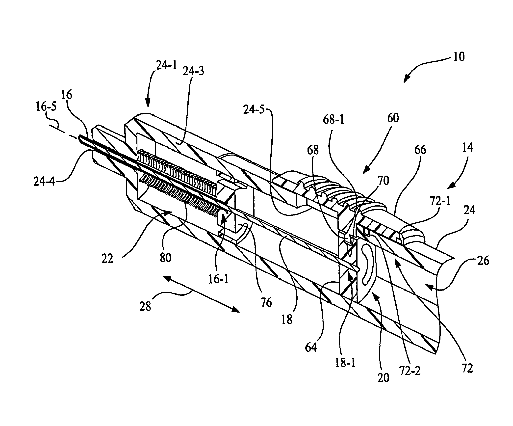
Referring again to FIGS. 1-3, deployment mechanism 20 is mounted to housing 24 of handle 14 and is configured to displace marker introducer rod 18 for deploying tissue marker 12 upon an actuation of deployment mechanism 20 by the user. In general, deployment mechanism 20 is configured to limit marker delivery device 10 to a single use for marker deployment. FIGS. 1 and 2 show deployment mechanism 20 in an initial position 60 (marker not deployed) and FIG. 3 shows deployment mechanism 20 in a marker deployed position 62.
More particularly, deployment mechanism 20 includes an introducer rod guide block 64, a marker deployment trigger 66, and a first shear member 68. Introducer rod guide block 64 is fixedly attached to the actuation end 18-1 of marker introducer rod 18, such as by molding a portion of marker introducer rod 18 into introducer rod guide block 64, and is slidably disposed in chamber 26 of housing 24. Marker deployment trigger 66 is accessible at an exterior of housing 24 of handle 14. Marker deployment trigger 66 is mounted to housing 24 for siding movement along trigger slot 24-5 of housing 24 from the initial position 60 shown in FIGS. 1 and 2 toward the front end 24-1 of housing 24 to position deployment mechanism 20 at the marker deployed position 62.
In the present embodiment, marker deployment trigger 66 and introducer rod guide block 64 are linked by first shear member 68. First shear member 68 extends from marker deployment trigger 66 and resides in a recess 70 located in introducer rod guide block 64. Thus, an actuation of marker deployment trigger 66 causes first shear member 68 to displace introducer rod guide block 64, which in turn displaces marker introducer rod 18 along the lengthwise extent 28 of cannula 16 to deploy tissue marker 12 from lumen 16-4 of cannula 16. First shear member 68 has a region of reduced cross section dimension 68-1, e.g., an annular groove, to provide a shear location.
An outer contour of introducer rod guide block 64 may be selected to be slidably received in a like-inner contour of longitudinal chamber 26 of housing 24 of handle 14. Accordingly, in embodiments where the outer contour of introducer rod guide block 64 and the like-inner contour of longitudinal chamber 26 are non-circular, introducer rod guide block 64 prevents rotation of marker introducer rod 18 with respect to housing 24 of handle 14, thus maintaining a constant orientation of marker introducer rod 18 relative to handle 14.
Also, in embodiments where the outer contour of introducer rod guide block 64 and the like-inner contour of longitudinal chamber 26 are circular, recess 70 of introducer rod guide block 64 may be in the form of a circumferential groove to facilitate a change in angular position, i.e., rotation, of marker introducer rod 18 with respect to housing 24 of handle 14. In such case, a rotator, e.g., knob, (not shown) positioned external to handle 14 may be coupled to introducer rod guide block 64 to effect a change in orientation of marker introducer rod 18 relative to handle 14.
As best shown in FIG. 2, deployment mechanism 20 may further include a lock mechanism 72 to lock marker deployment trigger 66 in the marker deployed position 62 after tissue marker 12 has been deployed. In the present embodiment, lock mechanism 72 includes a first lock member 72-1 formed on, or attached to, marker deployment trigger 66 and includes a second lock member 72-2 formed on, or attached to, housing 24. In operation, first lock member 72-1 permanently engages second lock member 72-2 when marker deployment trigger 66 is positioned in the marker deployed position 62, thereby limiting marker delivery device 10 to a single marker deployment operation.
One of first lock member 72-1 and second lock member 72-1 may be, for example, a lock channel and the other of first lock member 72-1 and second lock member 72-2 may be a spring-loaded insert member that engages the lock channel when marker deployment trigger 66, and in turn marker introducer rod 18, is positioned in marker deployed position 62. In the present embodiment shown in FIG. 2, for example, first lock member 72-1 is formed as a lock channel in marker deployment trigger 66, and second lock member 72-2 is in the form of a spring-loaded pin that engages the lock channel when marker deployment trigger 66 is slid toward the front end 24-1 of housing 24 to position deployment mechanism 20, and in turn marker introducer rod 18, in marker deployed position 62. As a further example, when second lock member 72-2 is formed as a lock channel in housing 24, the lock channel may be formed by, or integral with, trigger slot 24-5, and first lock member 72-1 as a spring-loaded insert member may be a cantilevered arm having a protrusion that engages the lock channel when marker deployment trigger 66 is positioned in marker deployed position 62.
Again referring to FIGS. 1-3, retraction mechanism 22 is mounted to housing 24 of handle 14 and is configured to facilitate a complete retraction of both cannula 16 and marker introducer rod 18 into chamber 26 of housing 24 of handle 14 upon an actuation of retraction mechanism 22 by the user, which most likely will occur following deployment of tissue marker 12. Retraction mechanism 22 is configured to prevent cannula 16 and marker introducer rod 18 from extending outside chamber 26 of housing 24 of handle 14 after the complete retraction of cannula 16 and marker introducer rod 18 into chamber 26, thus facilitating the safe disposal of marker delivery device 10, and alleviating concern about the accidental puncturing of medical personnel, or the patient, following the use of marker delivery device 10.
More particularly, retraction mechanism 22 includes a retraction trigger 74, a cannula guide block 76, a second shear member 78, and a spring 80. Retraction trigger 74 may be in the form of a push button that is accessible at the exterior of the housing 24, e.g., through a hole 24-7 in side wall 24-3. Cannula guide block 76 is fixedly attached to the proximal end 16-1 of cannula 16, such as by molding a portion of cannula 16 into cannula guide block 76. Cannula guide block 76 is slidably disposed in longitudinal chamber 26 of housing 24. In the present embodiment, second shear member 78 is formed as an extension of retraction trigger 74.
As best shown in FIG. 3, retraction trigger 74 and cannula guide block 76 are linked by second shear member 78 that is resident in a recess 82 located in cannula guide block 76, thus holding cannula guide block 76 stationary, e.g., axially stationary, relative to housing 24 of handle 14. Spring 80 is located between the front end 24-1 of housing 24 and cannula guide block 76, with spring 80 being in a compressed state prior to actuation of retraction trigger 74, thus providing a preload on cannula guide block 76.
An outer contour of cannula guide block 76 may be selected to be slidably received in an inner like-contour of longitudinal chamber 26 of housing 24 of handle 14. Accordingly, in embodiments where the outer contour of cannula guide block 76 and the inner like-contour of longitudinal chamber 26 are non-circular, cannula guide block 76 prevents rotation of cannula 16 with respect to housing 24 of handle 14, thus maintaining a constant orientation of cannula 16 relative to handle 14.
However, in embodiments where the outer contour of cannula guide block 76 and the inner like-contour of longitudinal chamber 26 are circular, recess 82 of cannula guide block 76 may be in the form of a circumferential groove to facilitate a change in angular position, i.e., rotation, of cannula 16 with respect to housing 24 of handle 14, thus facilitating a changeable orientation of cannula 16 relative to handle 14. In such case, cannula 16 may be manually rotated by grasping cannula 16 and turning. Alternatively, a rotator, e.g., knob, (not shown) positioned external to handle 14 may be coupled to guide block 76 to effect a change in orientation of cannula 16 relative to handle 14.
An actuation of retraction trigger 74 causes a complete retraction of both cannula 16 and marker introducer rod 18 into chamber 26 of housing 24 of handle 14. More particularly, as shown in FIG. 3, second shear member 78 has a region of reduced cross section dimension 78-1, e.g., an annular groove, to provide a shear location. Initially, the region of reduced cross section dimension 78-1 of second shear member 78 is contained within the hole 24-7 formed in side wall 24-3, thereby providing additional support at the region of reduced cross section dimension 78-1.
In the present embodiment, an actuation (depressing) of retraction trigger 74 radially displaces second shear member 78 causing second shear member 78 to shear. More particularly, by depressing retraction trigger 74, the region of reduced cross section dimension 78-1 of second shear member 78 enters longitudinal chamber 26 through side wall 24-3 of housing 24, such that the region of reduced cross section dimension 78-1 of second shear member 78 is no longer supported by side wall 24-3, and whereby the spring force exerted by spring 80 overcomes the shear resistance of the region of reduced cross section dimension 78-1 of second shear member 78. The shearing of second shear member 78 results in a release of spring 80 from the compressed state shown in FIGS. 1-3 to force cannula guide block 76 to move toward the back end 24-2 of housing 24 to begin an initial retraction of cannula 16, and wherein a continued decompression of spring 80 causes cannula guide block 76 to impact introducer rod guide block 64 to shear first shear member 68, whereby beginning a simultaneous retraction of both cannula 16 and marker introducer rod 18 into chamber 26 of housing 24 of handle 14. The simultaneous retraction of both cannula 16 and marker introducer rod 18 into handle 14 terminates after both cannula 16 and marker introducer rod 18 are completely contained in longitudinal chamber 26 of housing 24 of handle 14, as illustrated in FIG. 9.
Alternatively, a spacing device 84 (see FIG. 1) may be positioned between introducer rod guide block 64 and cannula guide block 76. Spacing device 84 has a length along the lengthwise extent 28 such that cannula guide block 76 is in operable contact with introducer rod guide block 64 when introducer rod guide block 64 is positioned in the marker deployed position 62, such that first shear member 68 and second shear member 78 are sheared substantially simultaneously when retraction trigger 74 displaced, resulting in a complete simultaneous retraction of both cannula 16 and marker introducer rod 18 into chamber 26 of housing 24.
FIGS. 10-15 depict another embodiment of the invention, depicting a marker delivery device 110 that includes a handle 112, cannula 16, marker introducer rod 18, a deployment mechanism 114 and a cannula retraction mechanism 116. Cannula 16 and marker introducer rod 18 may be configured as previously described, and thus for brevity the full details of their operation will not be repeated here. Marker delivery device 110 functionally differs from the embodiment of marker delivery device 10, in that deployment mechanism 114 of marker delivery device 110 may be configured to facilitate a full retraction of marker introducer rod 18 prior to beginning the retraction of cannula 16 effected by cannula retraction mechanism 116.
Handle 112 is configured of an appropriate size and shape to be grasped by the hand of the user of marker delivery device 110. Handle 112 includes a housing 118 having a front end 118-1, a back end 118-2 and a side wall 118-3, with a longitudinal chamber 120 located between front end 118-1 and back end 118-2 that is surrounded by side wall 118-3. A hole 118-4 leads from longitudinal chamber 120 through the front end 118-1 of housing 118 to the exterior of handle 112. Cannula 16 is positioned in handle 112 such that cannula 16 initially extends through hole 118-4 beyond the front end 118-1 of housing 118 prior to marker deployment. A trigger slot 118-5 extends through side wall 118-3 of housing 118.
Deployment mechanism 114 is mounted to housing 118 of handle 112 and is configured to displace marker introducer rod 18 for deploying tissue marker 12 upon an actuation of deployment mechanism 114 by the user. FIGS. 10 and 11 show deployment mechanism 114 in an initial position 121 (unused, marker not deployed), FIG. 12 shows deployment mechanism 114 in a marker deployed position 122, FIG. 13 shows deployment mechanism 114 in a marker introducer rod initial retraction position 124, and FIG. 14 shows deployment mechanism 114 in a marker introducer rod post-initial retraction position 126.
Deployment mechanism 114 includes an introducer rod guide block 128, a multi-stage marker deployment trigger 130, a first shear member 132, and an introducer rod retraction spring 133. First shear member 132 has a region of reduced cross section dimension 132-1, e.g., an annular groove, to provide a shear location. Introducer rod guide block 128 is attached to the actuation end 18-1 of marker introducer rod 18, and is slidably disposed in longitudinal chamber 120 of housing 118. Marker deployment trigger 130 is accessible at an exterior of housing 118 of handle 112. Marker deployment trigger 130 includes an inner sleeve 130-1 and an outer actuator 130-2. Marker deployment trigger 130 is mounted to housing 118 for siding movement along trigger slot 118-5.
FIGS. 11-14 show various stages of movement of inner sleeve 130-1 and an outer actuator 130-2 of marker deployment trigger 130. In the present embodiment, marker deployment trigger 130 and introducer rod guide block 128 are linked by first shear member 132. First shear member 132 extends from inner sleeve 130-1 of marker deployment trigger 130 and resides in a recess 134 located in introducer rod guide block 128.
Initially, as shown in FIG. 11, inner sleeve 130-1 and outer actuator 130-2 of marker deployment trigger 130 are linked by a drive tab 136 mounted to inner sleeve 130-1 that engages a drive slot 138 formed in outer actuator 130-2, so that inner sleeve 130-1 and outer actuator 130-2 initially move concurrently. Drive slot 138 is defined by a downward facing lip 140 that separates drive slot 138 from an elongate introducer rod retraction slot 142. Drive tab 136 may be hinge-mounted, e.g., by a linking membrane, to inner sleeve 130-1. Drive tab 136 includes an upwardly extending protrusion 136-1 that is initially engaged with lip 140 in drive slot 138. Introducer rod retraction spring 133 is positioned between cannula retraction mechanism 116 and introducer rod guide block 128 under slight compression, and more particularly, between introducer rod guide block 128 and cannula guide block 156.
Referring to FIG. 12, an actuation of marker deployment trigger 130 by sliding outer actuator 130-2 of marker deployment trigger 130 toward the front end 118-1 of housing 118 of handle 112 causes inner sleeve 130-1 to move first shear member 132 longitudinally along longitudinal chamber 120 to displace introducer rod guide block 128, which in turn displaces marker introducer rod 18 along the lengthwise extent 28 of cannula 16 to deploy tissue marker 12 from lumen 16-4 of cannula 16 when the marker deployed position 122 depicted in FIG. 12 is reached. At this stage, introducer rod retraction spring 133 is being compressed. Housing 118 includes an indicator line 144, such that when a leading edge 146 of inner sleeve 130-1 aligns with indicator line 144 to indicate that the marker deployed position 122 has been reached, the user is assured of a complete deployment of tissue marker 12 out of the distal end 16-2 of cannula 16.
Also, as depicted in FIG. 12, when marker deployment trigger 130 is positioned at marker deployed position 122, drive tab 136 is positioned over a retraction channel 148 in housing 118. A further sliding of outer actuator 130-2 of marker deployment trigger 130 toward the front end 118-1 of housing 118 of handle 112 causes lip 140 forming a trailing edge of drive slot 138 to force protrusion 136-1 of drive tab 136 to twist forward into a deformation downward into a retraction channel 148 formed in housing 118 of handle 112, thereby allowing lip 140 to begin to pass over protrusion 136-1 of drive tab 136. At this stage, introducer rod retraction spring 133 has reached maximum compression.
As depicted in FIG. 13, the further sliding of outer actuator 130-2 of marker deployment trigger 130 toward the front end 118-1 of housing 118 of handle 112 causes lip 140 to pass over the upward protrusion 136-1 of drive tab 136, thereby allowing drive tab 136 to regain its original geometry with respect inner sleeve 130-1, thereby moving upwardly out of retraction channel 148. This action occurs when the leading edge 150 of outer actuator 130-2 aligns with indicator line 152 of inner sleeve 130-1. At this stage, introducer rod retraction spring 133 starts to decompress. Accordingly, a portion of deployment mechanism 114, e.g., inner sleeve 130-1, outer actuator 130-2, drive tab 136, lip 140, and retraction channel 148 of deployment mechanism 114, also functions as an introducer rod retraction mechanism 153 for marker introducer rod 18.
As depicted in FIG. 14, with upward protrusion 136-1 of drive tab 136 fully released from retraction channel 148 and upward protrusion 136-1 of drive tab 136 being positioned in introducer rod retraction slot 142, the decompression of introducer rod retraction spring 133 forces introducer rod guide block 128 toward the back end 118-2 of housing 118 (see FIG. 10), and in turn marker introducer rod 18 and inner sleeve 130-1 are returned toward their initial positions as depicted in FIGS. 10 and 11. The spring force provided by introducer rod retraction spring 133 may be selected, for example, such that the impact of inner sleeve 130-1 with end wall 118-6 of housing 118 causes first shear member 132 to shear at the region of reduced cross section dimension 132-1, thereby facilitating a complete retraction of marker introducer rod 18 into longitudinal chamber 120, prior to initiating retraction of cannula 16.
Alternatively, the spring force provided by introducer rod retraction spring 133 may be selected, for example, such that the impact of inner sleeve 130-1 with end wall 118-6 of housing 118 stops the retraction of marker introducer rod 18 into longitudinal chamber 120 after a partial retraction of marker introducer rod 18, prior to initiating retraction of cannula 16.
Also, as depicted in FIG. 14, at this stage outer actuator 130-2 of marker deployment trigger 130 is no longer linked to inner sleeve 130-1. Thus, a subsequent extension of marker introducer rod 18 by actuation of outer actuator 130-2 of marker deployment trigger 130 is prevented, thereby rendering marker delivery device 110 usable for only a single tissue marker deployment.
Referring again also to FIG. 10 in relation to FIGS. 14 and 15, cannula retraction mechanism 116 is mounted to housing 118 of handle 112 and is configured to facilitate a complete retraction of cannula 16 into longitudinal chamber 120 of housing 118 of handle 112 upon an actuation of cannula retraction mechanism 116 by the user, which most likely will occur following deployment of tissue marker 12. FIG. 15 shows cannula retraction mechanism 116, with marker introducer rod 18 in marker deployed position 122. Cannula retraction mechanism 116 is configured to prevent cannula 16 and marker introducer rod 18 from extending outside longitudinal chamber 120 of housing 118 of handle 112 after the complete retraction of cannula 16 and marker introducer rod 18 into longitudinal chamber 120, thus facilitating the safe disposal of marker delivery device 110, and alleviating concern about the accidental puncturing of medical personnel, or the patient, following the use of marker delivery device 110.
Cannula retraction mechanism 116 includes a retraction trigger 154, a cannula guide block 156, a second shear member 158, and a cannula retraction spring 160. Retraction trigger 154 may be in the form of a push button that is accessible at the exterior of housing 118, e.g., through a hole 118-7 in side wall 118-3. Cannula guide block 156 is attached to the proximal end 16-1 of cannula 16. Cannula guide block 156 is slidably disposed in longitudinal chamber 120 of housing 118. In the present embodiment, second shear member 158 is formed as an extension of retraction trigger 154.
Retraction trigger 154 and cannula guide block 156 are linked by second shear member 158 that is resident in a recess 162 located in cannula guide block 156, thus holding cannula guide block 156 stationary relative to housing 118 of handle 112. Cannula retraction spring 160 is located between the front end 118-1 of housing 118 and cannula guide block 156, with cannula retraction spring 160 being in a compressed state prior to actuation of retraction trigger 154, thus providing a preload on cannula guide block 156.
An actuation of retraction trigger 154 causes a complete retraction of cannula 16 into longitudinal chamber 120 of housing 118 of handle 112. More particularly, as shown in FIG. 15, initially, the region of reduced cross section dimension 158-1 of second shear member 158 is supported by side wall 118-3, thereby providing additional support at the region of reduced cross section dimension 158-1. An actuation (depressing) of retraction trigger 154 radially displaces second shear member 158 causing the region of reduced cross section dimension 158-1 of second shear member 158 to enter longitudinal chamber 120 through side wall 118-3 of housing 118, such that the region of reduced cross section dimension 158-1 of second shear member 158 is no longer supported by the side wall 118-3, and whereby the spring force exerted by cannula retraction spring 160 overcomes the shear resistance of the region of reduced cross section dimension 158-1 of second shear member 158. The shearing of second shear member 158 results in a release of cannula retraction spring 160 from the compressed state shown to force cannula guide block 156 to move toward the back end 118-2 of housing 118 to complete a full retraction of cannula 16 into longitudinal chamber 120 of housing 118 of handle 112.
In the event of a partial retraction of marker introducer rod 18, or in the event that the user does not perform the previously described retraction of marker reducer rod, into longitudinal chamber 120 of housing 118 of handle 112 prior to actuation of retraction trigger 154 (as depicted in FIG. 15), the continued decompression of cannula retraction spring 160 causes cannula guide block 156 to impact introducer rod guide block 128 to shear first shear member 132, whereby facilitating a full simultaneous retraction of both cannula 16 and marker introducer rod 18 into longitudinal chamber 120 of housing 118 of handle 112.
The retraction process is completed when both cannula 16 and marker introducer rod 18 are completely contained in longitudinal chamber 120 of housing 118 of handle 112.
While this invention has been described with respect to at least one embodiment, the present invention can be further modified within the spirit and scope of this disclosure. This application is therefore intended to cover any variations, uses, or adaptations of the invention using its general principles. Further, this application is intended to cover such departures from the present disclosure as come within known or customary practice in the art to which this invention pertains and which fall within the limits of the appended claims.
* * * * *
References
D00000
D00001
D00002
D00003
D00004
D00005
D00006
D00007
D00008
D00009
D00010
D00011
D00012
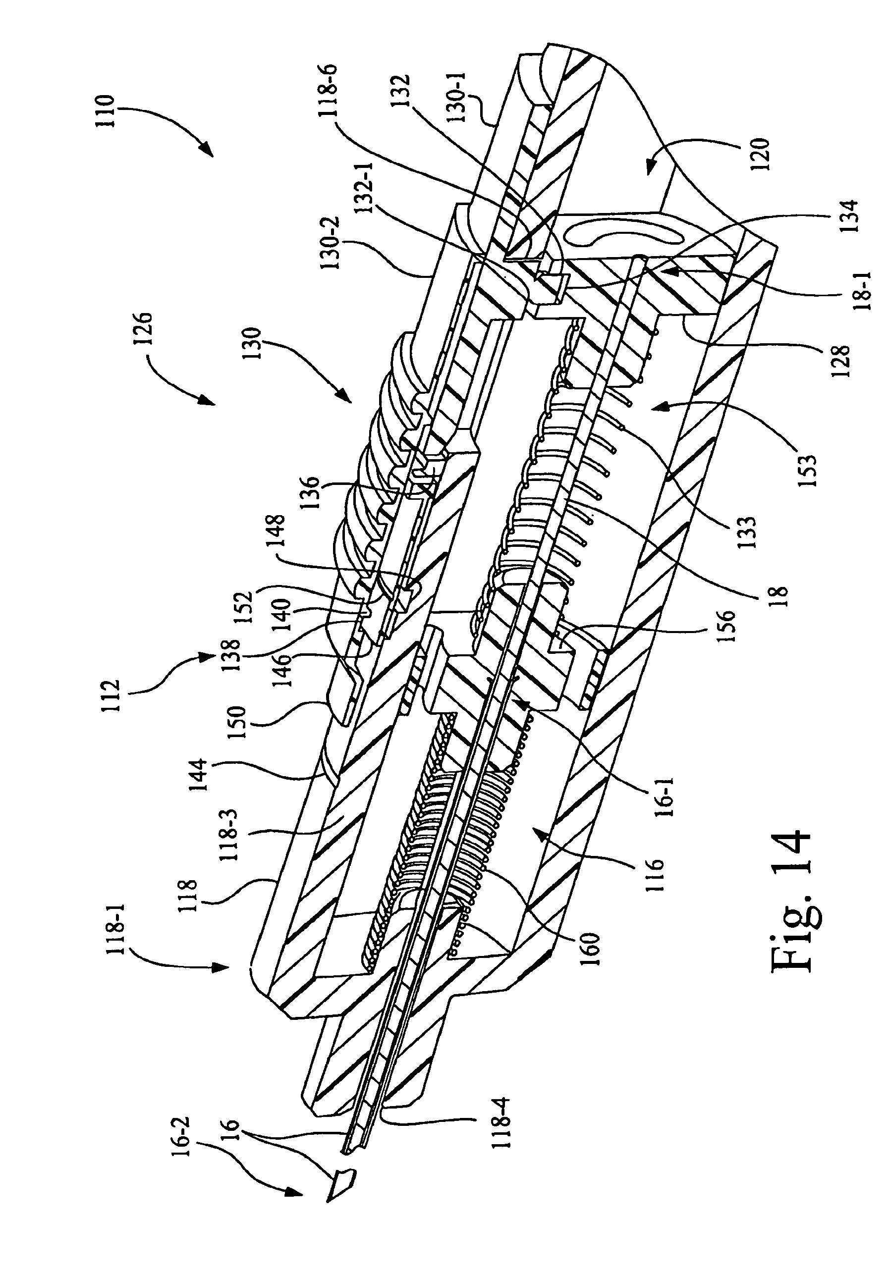
D00013
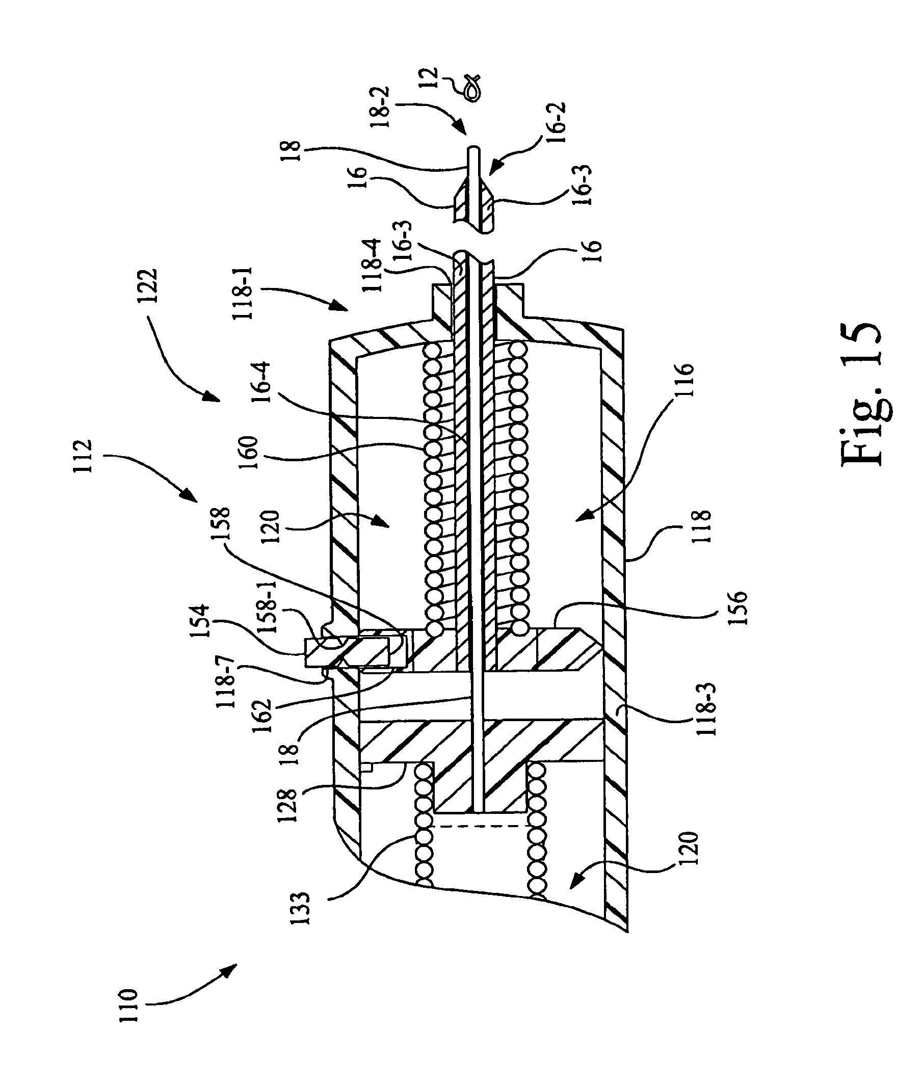
XML
uspto.report is an independent third-party trademark research tool that is not affiliated, endorsed, or sponsored by the United States Patent and Trademark Office (USPTO) or any other governmental organization. The information provided by uspto.report is based on publicly available data at the time of writing and is intended for informational purposes only.
While we strive to provide accurate and up-to-date information, we do not guarantee the accuracy, completeness, reliability, or suitability of the information displayed on this site. The use of this site is at your own risk. Any reliance you place on such information is therefore strictly at your own risk.
All official trademark data, including owner information, should be verified by visiting the official USPTO website at www.uspto.gov. This site is not intended to replace professional legal advice and should not be used as a substitute for consulting with a legal professional who is knowledgeable about trademark law.