Resonant power transmission coils and systems
Hansen
U.S. patent number 10,251,987 [Application Number 14/414,842] was granted by the patent office on 2019-04-09 for resonant power transmission coils and systems. This patent grant is currently assigned to TC1 LLC. The grantee listed for this patent is THORATEC CORPORATION. Invention is credited to John Freddy Hansen.


View All Diagrams
| United States Patent | 10,251,987 |
| Hansen | April 9, 2019 |
Resonant power transmission coils and systems
Abstract
An improved wireless transmission system for transferring power over a distance. The system includes a transmitter generating a magnetic field and a receiver for inducing a voltage in response to the magnetic field. In various respects, the receiver is configured to be implanted in a body. The receiver may include a housing enclosing a receiving coil and associated electronic components, a covering around at least a portion of the housing, and at least two wires wrapped around the housing to form a plurality of turns. The covering may be formed of a ferrite material configured to both magnetically shield a respective portion of the internal volume of the housing and redirect incoming magnetic flux from the transmitter to improve efficiency. Methods of use are also provided.
| Inventors: | Hansen; John Freddy (Pleasanton, CA) | ||||||||||
|---|---|---|---|---|---|---|---|---|---|---|---|
| Applicant: |
|
||||||||||
| Assignee: | TC1 LLC (St. Paul, MN) |
||||||||||
| Family ID: | 49997894 | ||||||||||
| Appl. No.: | 14/414,842 | ||||||||||
| Filed: | July 29, 2013 | ||||||||||
| PCT Filed: | July 29, 2013 | ||||||||||
| PCT No.: | PCT/US2013/052551 | ||||||||||
| 371(c)(1),(2),(4) Date: | January 14, 2015 | ||||||||||
| PCT Pub. No.: | WO2014/018973 | ||||||||||
| PCT Pub. Date: | January 30, 2014 |
Prior Publication Data
| Document Identifier | Publication Date | |
|---|---|---|
| US 20150222128 A1 | Aug 6, 2015 | |
Related U.S. Patent Documents
| Application Number | Filing Date | Patent Number | Issue Date | ||
|---|---|---|---|---|---|
| 61676718 | Jul 27, 2012 | ||||
| Current U.S. Class: | 1/1 |
| Current CPC Class: | H02J 5/005 (20130101); H02J 50/10 (20160201); A61M 1/127 (20130101); H02J 50/70 (20160201); H02J 50/12 (20160201); A61N 1/3787 (20130101); H01F 38/14 (20130101); A61M 1/101 (20130101); A61M 1/122 (20140204); A61M 2205/8243 (20130101) |
| Current International Class: | H02J 5/00 (20160101); H02J 50/12 (20160101); H02J 50/70 (20160101); A61N 1/378 (20060101); A61M 1/12 (20060101); H02J 50/10 (20160101); A61M 1/10 (20060101) |
References Cited [Referenced By]
U.S. Patent Documents
| 4041955 | August 1977 | Kelly et al. |
| 4352960 | October 1982 | Dormer et al. |
| 4561443 | December 1985 | Hogrefe et al. |
| 4561444 | December 1985 | Livingston et al. |
| 4630615 | December 1986 | Yomtov |
| 4679560 | July 1987 | Galbraith |
| 4726378 | February 1988 | Kaplan |
| 4736747 | April 1988 | Drake |
| 4924171 | May 1990 | Baba et al. |
| 4945305 | July 1990 | Blood |
| 5070223 | December 1991 | Colasante |
| 5346458 | September 1994 | Affeld |
| 5350413 | September 1994 | Miller |
| 5569156 | October 1996 | Mussivand |
| 5630836 | May 1997 | Prem et al. |
| 5690693 | November 1997 | Wang et al. |
| 5702431 | December 1997 | Wang et al. |
| 5755748 | May 1998 | Borza |
| 5771438 | June 1998 | Palermo et al. |
| 5831248 | November 1998 | Hojyo et al. |
| 5948006 | September 1999 | Mann |
| 6123726 | September 2000 | Mori et al. |
| 6149683 | November 2000 | Lancisi et al. |
| 6212430 | April 2001 | Kung |
| 6296533 | October 2001 | Grubbs et al. |
| 6312338 | November 2001 | Sato et al. |
| 6320354 | November 2001 | Sengupta et al. |
| 6324431 | November 2001 | Zarinetchi et al. |
| 6327504 | December 2001 | Dolgin et al. |
| 6389318 | May 2002 | Zarinetchi et al. |
| 6400991 | June 2002 | Kung |
| 6442434 | August 2002 | Zarinetchi et al. |
| 6451055 | September 2002 | Weiss |
| 6458164 | October 2002 | Weiss |
| 6478820 | November 2002 | Weiss |
| 6553263 | April 2003 | Meadows et al. |
| 6579315 | June 2003 | Weiss |
| 6591139 | July 2003 | Loftin et al. |
| 6605032 | August 2003 | Benkowski et al. |
| 6647298 | November 2003 | Abrahamson et al. |
| 6650213 | November 2003 | Sakurai et al. |
| 6723039 | April 2004 | French et al. |
| 6772011 | August 2004 | Dolgin |
| 6801807 | October 2004 | Abrahamson |
| 6810289 | October 2004 | Shaquer |
| 6850803 | February 2005 | Jimenez et al. |
| 6894456 | May 2005 | Tsukamoto et al. |
| 6895281 | May 2005 | Amundson et al. |
| 6949065 | September 2005 | Sporer et al. |
| 6960968 | November 2005 | Odendaal et al. |
| 6967621 | November 2005 | Cadotte, Jr. et al. |
| 6985773 | January 2006 | Von Arx et al. |
| 7015769 | March 2006 | Schulman et al. |
| 7107103 | September 2006 | Schulman et al. |
| 7126310 | October 2006 | Barron |
| 7225032 | May 2007 | Schmeling et al. |
| 7246040 | July 2007 | Borg et al. |
| 7286880 | October 2007 | Olson et al. |
| 7428438 | September 2008 | Parramon et al. |
| 7471986 | December 2008 | Hatlestad |
| 7496733 | February 2009 | Altman et al. |
| 7505816 | March 2009 | Schmeling et al. |
| 7515012 | April 2009 | Schulman et al. |
| 7522878 | April 2009 | Baarman |
| 7532901 | May 2009 | LaFranchise et al. |
| 7565187 | July 2009 | Dynok et al. |
| 7571007 | August 2009 | Erickson et al. |
| 7574173 | August 2009 | Terranova et al. |
| 7587241 | September 2009 | Parramon et al. |
| 7599743 | October 2009 | Hassler et al. |
| 7650187 | January 2010 | Gruber et al. |
| 7650192 | January 2010 | Wahlstrand |
| 7711433 | May 2010 | Davis et al. |
| 7720546 | May 2010 | Ginggen et al. |
| 7741734 | June 2010 | Joannopoulos et al. |
| 7761164 | July 2010 | Verhoef et al. |
| 7774069 | August 2010 | Olson et al. |
| 7782190 | August 2010 | Martin et al. |
| 7805200 | September 2010 | Kast et al. |
| 7812481 | October 2010 | Iisaka et al. |
| 7818036 | October 2010 | Lair et al. |
| 7818037 | October 2010 | Lair et al. |
| 7825543 | November 2010 | Karalis et al. |
| 7830114 | November 2010 | Reed |
| 7865245 | January 2011 | Torgerson et al. |
| 7872367 | January 2011 | Recksiek et al. |
| 7904170 | March 2011 | Harding |
| 7932696 | April 2011 | Peterson |
| 7962222 | June 2011 | He et al. |
| RE42682 | September 2011 | Barreras et al. |
| 8076801 | December 2011 | Karalis et al. |
| 8081925 | December 2011 | Parramon et al. |
| 8096954 | January 2012 | Stahmann et al. |
| 8140168 | March 2012 | Olson et al. |
| 8150529 | April 2012 | Snell et al. |
| 8165694 | April 2012 | Carbanaru et al. |
| 8185212 | May 2012 | Carbunaru et al. |
| 8193766 | June 2012 | Rondoni et al. |
| 8203434 | June 2012 | Yoshida |
| 8244367 | August 2012 | Wahlstrand et al. |
| 8247926 | August 2012 | Issa et al. |
| 8258653 | September 2012 | Kitamura et al. |
| 8265770 | September 2012 | Toy et al. |
| 8278784 | October 2012 | Cook et al. |
| 8292052 | October 2012 | Bohori et al. |
| 8299652 | October 2012 | Sample et al. |
| 8301079 | October 2012 | Baarman |
| 8319473 | November 2012 | Choi et al. |
| 8362742 | January 2013 | Kallmyer |
| 8373310 | February 2013 | Baarman et al. |
| 8378522 | February 2013 | Cook et al. |
| 8378523 | February 2013 | Cook et al. |
| 8463395 | June 2013 | Forsell |
| 8489200 | July 2013 | Zarinetchi et al. |
| 8551163 | October 2013 | Aber et al. |
| 8562508 | October 2013 | Dague et al. |
| 8581793 | November 2013 | Carr |
| 8587154 | November 2013 | Fells et al. |
| 8620447 | December 2013 | D'Ambrosio et al. |
| 8628460 | January 2014 | Yomtov et al. |
| 8629578 | January 2014 | Kurs et al. |
| 8668473 | March 2014 | Larose et al. |
| 8694117 | April 2014 | Aghassian et al. |
| 8810071 | August 2014 | Sauerlaender et al. |
| 8884468 | November 2014 | Lemmens et al. |
| 8909351 | December 2014 | Dinsmoor et al. |
| 8971958 | March 2015 | Frikart et al. |
| 9002468 | April 2015 | Shea et al. |
| 9106083 | August 2015 | Partovi |
| 9192704 | November 2015 | Yomtov et al. |
| 9302093 | April 2016 | Mashiach |
| 9515494 | December 2016 | Kurs et al. |
| 9515495 | December 2016 | Kurs et al. |
| 9560787 | January 2017 | Kallmyer et al. |
| 2002/0038138 | March 2002 | Zarinetchi et al. |
| 2002/0087204 | July 2002 | Kung et al. |
| 2002/0093456 | July 2002 | Sawamura et al. |
| 2003/0171792 | September 2003 | Zarinetchi |
| 2004/0138725 | July 2004 | Forsell |
| 2004/0256146 | December 2004 | Frericks |
| 2005/0006083 | January 2005 | Chen et al. |
| 2005/0288743 | December 2005 | Ahn |
| 2006/0199997 | September 2006 | Hassler et al. |
| 2006/0271129 | November 2006 | Tai et al. |
| 2007/0096686 | May 2007 | Jimenez et al. |
| 2007/0123948 | May 2007 | Dal Molin |
| 2007/0142696 | June 2007 | Crosby et al. |
| 2007/0191706 | August 2007 | Calderon et al. |
| 2008/0009198 | January 2008 | Marino |
| 2008/0027293 | January 2008 | Vodermayer et al. |
| 2008/0054638 | March 2008 | Greene et al. |
| 2008/0100294 | May 2008 | Rohling et al. |
| 2008/0149736 | June 2008 | Kim et al. |
| 2008/0167531 | July 2008 | McDermott |
| 2008/0211320 | September 2008 | Cook et al. |
| 2009/0018616 | January 2009 | Quick et al. |
| 2009/0051224 | February 2009 | Cook et al. |
| 2009/0072628 | March 2009 | Cook et al. |
| 2009/0081943 | March 2009 | Dobyns et al. |
| 2009/0174264 | July 2009 | Onishi et al. |
| 2009/0212736 | August 2009 | Baarman et al. |
| 2009/0226328 | September 2009 | Morello |
| 2009/0270679 | October 2009 | Hoeg et al. |
| 2009/0284220 | November 2009 | Toncich et al. |
| 2010/0019985 | January 2010 | Bashyam et al. |
| 2010/0033021 | February 2010 | Bennett |
| 2010/0035453 | February 2010 | Tronnes et al. |
| 2010/0045114 | February 2010 | Sample et al. |
| 2010/0063347 | March 2010 | Yomtov et al. |
| 2010/0066305 | March 2010 | Takahashi et al. |
| 2010/0069992 | March 2010 | Aghassian et al. |
| 2010/0109958 | May 2010 | Haubrich et al. |
| 2010/0114143 | May 2010 | Albrecht et al. |
| 2010/0122995 | May 2010 | Thomas et al. |
| 2010/0171368 | July 2010 | Schatz et al. |
| 2010/0184371 | July 2010 | Cook et al. |
| 2010/0194334 | August 2010 | Kirby et al. |
| 2010/0210233 | August 2010 | Cook et al. |
| 2010/0211134 | August 2010 | Forsell |
| 2010/0222848 | September 2010 | Forsell |
| 2010/0222849 | September 2010 | Forsell |
| 2010/0225174 | September 2010 | Jiang |
| 2010/0244576 | September 2010 | Hillan et al. |
| 2010/0253340 | October 2010 | Corum et al. |
| 2010/0256708 | October 2010 | Thornton et al. |
| 2010/0277121 | November 2010 | Hall et al. |
| 2010/0308939 | December 2010 | Kurs |
| 2010/0314946 | December 2010 | Budde et al. |
| 2010/0320843 | December 2010 | Kitamura |
| 2010/0331919 | December 2010 | DiGiore et al. |
| 2011/0025132 | February 2011 | Sato |
| 2011/0043050 | February 2011 | Yabe et al. |
| 2011/0046699 | February 2011 | Mazanec |
| 2011/0057607 | March 2011 | Carobolante |
| 2011/0101790 | May 2011 | Budgett |
| 2011/0109263 | May 2011 | Sakoda et al. |
| 2011/0115431 | May 2011 | Dunworth et al. |
| 2011/0127848 | June 2011 | Ryu et al. |
| 2011/0148215 | June 2011 | Marzetta et al. |
| 2011/0178361 | July 2011 | Yomtov |
| 2011/0181235 | July 2011 | Walley et al. |
| 2011/0205083 | August 2011 | Janna et al. |
| 2011/0234155 | September 2011 | Chen |
| 2011/0241436 | October 2011 | Furukawa |
| 2011/0245892 | October 2011 | Kast et al. |
| 2011/0266880 | November 2011 | Kim et al. |
| 2011/0276110 | November 2011 | Whitehurst et al. |
| 2011/0278948 | November 2011 | Forsell |
| 2011/0291489 | December 2011 | Tsai et al. |
| 2011/0291613 | December 2011 | Rosik et al. |
| 2011/0295345 | December 2011 | Wells et al. |
| 2011/0298294 | December 2011 | Takada et al. |
| 2011/0301667 | December 2011 | Olson et al. |
| 2011/0313238 | December 2011 | Reichenbach et al. |
| 2012/0001485 | January 2012 | Uchida |
| 2012/0032522 | February 2012 | Schatz et al. |
| 2012/0039102 | February 2012 | Shinoda |
| 2012/0057322 | March 2012 | Waffenschmidt |
| 2012/0065458 | March 2012 | tol |
| 2012/0080957 | April 2012 | Cooper et al. |
| 2012/0091951 | April 2012 | Sohn |
| 2012/0104997 | May 2012 | Carobolante |
| 2012/0109256 | May 2012 | Meskins et al. |
| 2012/0119914 | May 2012 | Uchida |
| 2012/0146575 | June 2012 | Armstrong et al. |
| 2012/0149229 | June 2012 | Kearsley et al. |
| 2012/0150259 | June 2012 | Meskens |
| 2012/0153739 | June 2012 | Cooper et al. |
| 2012/0153954 | June 2012 | Ota et al. |
| 2012/0157753 | June 2012 | D'Ambrosio |
| 2012/0157754 | June 2012 | D'Ambrosio |
| 2012/0158407 | June 2012 | Forsell |
| 2012/0161539 | June 2012 | Kim et al. |
| 2012/0164943 | June 2012 | Bennett |
| 2012/0169132 | July 2012 | Choudhary et al. |
| 2012/0169133 | July 2012 | Lisi et al. |
| 2012/0169137 | July 2012 | Lisi et al. |
| 2012/0169139 | July 2012 | Kudo |
| 2012/0169278 | July 2012 | Choi et al. |
| 2012/0175967 | July 2012 | Dibben et al. |
| 2012/0235364 | September 2012 | Wang et al. |
| 2012/0239118 | September 2012 | Ozawa et al. |
| 2012/0245649 | September 2012 | Bohori et al. |
| 2012/0245664 | September 2012 | Smith et al. |
| 2012/0259398 | October 2012 | Chen et al. |
| 2012/0274148 | November 2012 | Sung et al. |
| 2012/0306433 | December 2012 | Kim et al. |
| 2013/0007949 | January 2013 | Kurs et al. |
| 2013/0060103 | March 2013 | Bergida et al. |
| 2013/0119773 | May 2013 | Davis |
| 2013/0127253 | May 2013 | Stark et al. |
| 2013/0149960 | June 2013 | Dec et al. |
| 2013/0159956 | June 2013 | Verghese et al. |
| 2013/0190551 | July 2013 | Callaway et al. |
| 2013/0197607 | August 2013 | Wilder et al. |
| 2013/0214731 | August 2013 | Dinsmoor |
| 2013/0241306 | September 2013 | Aber et al. |
| 2013/0241468 | September 2013 | Moshfeghi |
| 2013/0271088 | October 2013 | Hwang et al. |
| 2013/0289334 | October 2013 | Badstibner et al. |
| 2013/0310630 | November 2013 | Smith et al. |
| 2013/0320773 | December 2013 | Schatz et al. |
| 2013/0331638 | December 2013 | Cameron et al. |
| 2014/0005466 | January 2014 | Crosby et al. |
| 2014/0011447 | January 2014 | Konanur et al. |
| 2014/0028110 | January 2014 | Petersen et al. |
| 2014/0028111 | January 2014 | Hansen et al. |
| 2014/0031606 | January 2014 | Hansen et al. |
| 2014/0152252 | June 2014 | Wood |
| 2014/0163644 | June 2014 | Scott et al. |
| 2014/0265620 | September 2014 | Hoarau et al. |
| 2014/0265621 | September 2014 | Wong et al. |
| 2014/0275727 | September 2014 | Bonde et al. |
| 2015/0123654 | May 2015 | Gagnon et al. |
| 2015/0229289 | August 2015 | Suzuki |
| 2015/0290373 | October 2015 | Rudser et al. |
| 2016/0135684 | May 2016 | Kappel et al. |
| 2016/0218432 | July 2016 | Pope et al. |
| 2016/0250484 | September 2016 | Nguyen et al. |
| 2016/0254703 | September 2016 | Hansen |
| 2016/0254704 | September 2016 | Hansen et al. |
| 202012000166 | Jun 2013 | DE | |||
| 102012201073 | Jul 2013 | DE | |||
| 0589608 | Sep 1993 | EP | |||
| 1513241 | Mar 2005 | EP | |||
| 2267864 | Jun 2010 | EP | |||
| 2477034 | Jul 2011 | GB | |||
| H03109063 | May 1991 | JP | |||
| 11-506646 | Jun 1999 | JP | |||
| 2013094456 | May 2013 | JP | |||
| 2013161640 | Aug 2013 | JP | |||
| 2014160611 | Sep 2014 | JP | |||
| 1020020089605 | Nov 2002 | KR | |||
| 1020120007296 | Jan 2012 | KR | |||
| 1020120077448 | Jul 2012 | KR | |||
| 0001442 | Jan 2000 | WO | |||
| WO00/74747 | Dec 2000 | WO | |||
| WO01/37926 | May 2001 | WO | |||
| WO2005/106901 | Nov 2005 | WO | |||
| 2007053881 | May 2007 | WO | |||
| WO2008/066941 | Jun 2008 | WO | |||
| WO2009/018271 | Feb 2009 | WO | |||
| WO2009/021220 | Feb 2009 | WO | |||
| WO2009/023905 | Feb 2009 | WO | |||
| WO2009/042977 | Apr 2009 | WO | |||
| WO2010/030378 | Mar 2010 | WO | |||
| WO2010/089354 | Aug 2010 | WO | |||
| 2011081626 | Jul 2011 | WO | |||
| WO2011/113934 | Sep 2011 | WO | |||
| WO2012/002063 | Jan 2012 | WO | |||
| WO2012/056365 | May 2012 | WO | |||
| WO2012/087807 | Jun 2012 | WO | |||
| WO2012/087811 | Jun 2012 | WO | |||
| WO2012/087816 | Jun 2012 | WO | |||
| WO2012/087819 | Jun 2012 | WO | |||
| 2012099965 | Jul 2012 | WO | |||
| WO2012/141752 | Oct 2012 | WO | |||
| 2013110602 | Aug 2013 | WO | |||
| WO2013/138451 | Sep 2013 | WO | |||
| WO2014/039673 | Mar 2014 | WO | |||
Other References
|
Notification of Transmittal of the International Search Report and the Written Opinion of the International Searching Authority for PCT Application No. PCT/US2015/051474, dated Dec. 30, 2015. cited by applicant . Development and Implementation of RFID Technology, Ed. Cristina Turcu, Feb. 2009, pp. 28-30, 93-97. cited by applicant . Merli, Francesco, et al., "Design, Realization and Measurements of a Miniature Antenna for Implantable Wireless Communication Systems", IEEE Transaction on Antennas and Propagation, vol. 59, No. 10, Oct. 2011, pp. 3544-3555. cited by applicant . Merli, Francesco, et al.,"The Effect of Insulating Layers on the Performance of Implanted Antennas", IEEE Transaction on Antennas and Propagation, vol. 59, No. 1, Jan. 2011, pp. 21-31. cited by applicant . Abadia, Javier, et al., 3D-Spiral Small Antenna Design and Realization for Biomdical Telemetry in the MICS Band. Radioengineering, vol. 18, No. 4, Dec. 2009, pp. 359-367. cited by applicant . Petersen et al.; U.S. Appl. No. 14/414,708 entitled "Wireless Battery Charging," filed Jan. 14, 2015. cited by applicant . Petersen, E.; U.S. Appl. No. 14/414,820 entitled "Variable Capacitor for Resonant Power Transfer Systems," filed Jan. 14, 2015. cited by applicant . Petersen, E.; U.S. Appl. No. 14/414,823 entitled "Resonant Power Transfer System and Method of Estimating System State," filed Jan. 14, 2015. cited by applicant . Hansen, J.; U.S. Appl. No. 14/414,832 entitled "Resonant Power Transfer Systems With Protective Algorithm," filed Jan. 14, 2015. cited by applicant . Bonde et al.; Promise of unrestricted mobility with innovative, portable wireless powering of a mechanical circulatory assist device; American Association for Thoracic Surgery; .COPYRGT.2012; 2 pgs.; retrieved Mar. 12, 2014 from the internet: http://aats.org/annualmeeting/Abstracts/2012/T8.cgi. cited by applicant . Chargepoint, Inc.; -chargepoin+.RTM.; product brochure; 4 pgs.; .COPYRGT.2014; retrieved Mar. 12, 2014 from the internet: http://www.chargepoint.com/network/. cited by applicant . Dixon, Jr.; Eddy current losses in transformer windings and circuit wiring; Unitrode Corp. Seminar Manual (SEM600); Watertown, MA; 12 pgs.; 1988 (year of pub. sufficiently earlier than effective US filing date and any foreign priority date). cited by applicant . Evatran; PluglessTM Level 2 EV Charging System (3.3kW); product brochure; 7 pgs.; retrieved Mar. 12, 2014 from the internet: http://www.pluglesspower.com/tech-specs/. cited by applicant . Ferret, B.; Electric vehicles get big boost!; Renewable Energy World; 3 pgs.; Jul. 30, 2012; retrieved Jul. 30, 2012 from the internet: http://www.renewableenergyworld.com/rea/blog/post/2012/07/. cited by applicant . Motavalli, Jim; WiTricity Takes Its Car-Charging Technology Out for a Road Test; New York Times; 3 pgs.; Jul. 25, 2012; retrieved Mar. 12, 2014 from the internet: http://wheels.blogs.nytimes.com/2012/07/25/witricity-takes-its-car-chargi- ng-technology-out-for-a-road-test/. cited by applicant . Petersen et al.; U.S. Appl. No. 14/414,840 entitled "Computer Modeling for Resonant Power Transfer Systems," filed Jan. 14, 2015. cited by applicant. |
Primary Examiner: Barnie; Rexford
Assistant Examiner: Willoughby; Terrence
Attorney, Agent or Firm: Armstrong Teasdale LLC
Parent Case Text
CROSS-REFERENCE TO RELATED APPLICATIONS
This application claims the benefit of U.S. Provisional Patent Application No. 61/676,718, filed on Jul. 27, 2012, titled "Resonant Power Transmission Coils and Systems".
Claims
What is claimed is:
1. An implantable receiver configured to receive wireless energy, comprising: a housing defining an interior space containing internal components susceptible to interference by magnetic flux; a covering disposed on at least two sides of the housing, the covering being formed of a ferrite material, wherein for each side of the at least two sides, the covering comprises a plurality of adjacent tiles disposed on the associated side, wherein a first set of tiles are disposed on a first side of the housing and a second set of tiles are disposed on a second side of the housing, wherein each of the plurality of adjacent tiles includes a plurality of edge faces, an inner face facing the housing, and an outer face opposite the inner face, wherein the outer face has a larger surface area than each edge face, wherein a first tile on the first side of the housing overlaps a second tile on the second side of the housing to eliminate gaps between the first tile and the second tile, wherein the first tile has a first orientation such that the outer face of the first tile faces a first direction and the second tile has a second orientation such that the outer face of the second tile faces a second direction, and wherein the first orientation is different from the second orientation; and at least two wires wrapped around the housing to form a receiver coil.
2. The receiver of claim 1, wherein the internal components comprise receiver circuitry configured to transmit power excited in the receiver coil in response to an incoming magnetic flux to a load connected to the implantable receiver.
3. The receiver of claim 2, wherein the load is an implantable medical device including an operative component.
4. The receiver of claim 3, wherein the operative component is a circulatory support device.
5. The receiver of claim 3, wherein the operative component is a blood pump.
6. The receiver of claim 1, wherein the covering covers an entire periphery of the housing.
7. The receiver of claim 1, wherein the covering redirects incoming magnetic flux from an external transmitter towards the receiver coil to improve power transfer efficiency.
8. The receiver of claim 1, wherein the first orientation is orthogonal to the second orientation.
9. The receiver of claim 1, wherein the first tile and the second tile have different shapes.
10. The receiver of claim 9, wherein the first tile is rectangular and the second tile is square shaped.
11. A method of improving efficiency in a wireless power transfer system, comprising the steps of: generating magnetic flux with an external transmitter positioned near a patient towards a receiver implanted in the patient; and directing the magnetic flux towards a receiver coil of the receiver with a ferrite covering that surrounds at least two sides of a housing of the receiver, the housing defining an interior space, wherein for each side of the at least two sides, the covering comprises a plurality of adjacent tiles disposed on the associated side, wherein a first set of tiles are disposed on a first side of the housing and a second set of tiles are disposed on a second side of the housing, wherein each of the plurality of adjacent tiles includes a plurality of edge faces, an inner face facing the housing, and an outer face opposite the inner face, wherein the outer face has a larger surface area than each edge face, wherein a first tile on the first side of the housing has a first size, and a second tile on the second side of the housing has a second size, and wherein the first size is different from the second size.
12. The method of claim 11, wherein the first tile on the first side of the housing overlaps the second tile on the second side of the housing to eliminate gaps between the first tile and the second tile, wherein the first tile has a first orientation such that the outer face of the first tile faces a first direction and the second tile has a second orientation such that outer face of the second faces a second direction, and wherein the first orientation is different from the second orientation.
13. The method of claim 12, wherein the first orientation is orthogonal to the second orientation.
14. The method of claim 11, wherein the first tile is rectangular and the second tile is square shaped.
Description
INCORPORATION BY REFERENCE
All publications and patent applications mentioned in this specification are herein incorporated by reference to the same extent as if each individual publication or patent application was specifically and individually indicated to be incorporated by reference.
FIELD
This disclosure relates generally to methods and apparatus for transmitting and receiving power wirelessly, and in various respects, mechanical circulatory support.
BACKGROUND
Powered devices need to have a mechanism to supply power to the operative parts. Typically systems use a physical power cable to transfer energy over a distance. There has been a continuing need for systems that can transmit power efficiently over a distance without physical structures bridging the physical gap.
Systems and methods that supply power without electrical wiring are sometimes referred to as wireless energy transmission (WET). Wireless energy transmission greatly expands the types of applications for electrically powered devices. One such example is the field of implantable medical devices. Implantable medical devices typically require an internal power source able to supply adequate power for the reasonable lifetime of the device or an electrical cable that traverses the skin. Typically an internal power source (e.g. battery) is feasibly for only low power devices like sensors. Likewise, a transcutaneous power cable significantly affects quality of life (QoL), infection risk, and product life, among many drawbacks.
More recently there has been an emphasis on systems that supply power to an implanted device without using transcutaneous wiring. This is sometimes referred to as a Transcutaneous Energy Transfer System (TETS). Frequently energy transfer is accomplished using two magnetically coupled coils set up like a transformer so power is transferred magnetically across the skin. Conventional systems are relatively sensitive to variations in position and alignment of the coils. In order to provide constant and adequate power, the two coils need to be physically close together and well aligned.
Other solutions have focused on making one or both of the coils larger so the magnetic flux field is larger. This provides greater freedom of movement of the coils while ensuring efficient power transfer. This approach has several drawbacks. Because the components are implanted in the body, a larger receiving coil makes surgical placement more difficult and limits the implantation options. In cases where the transmitter is large relative to the receiver, it is likely the transmitter will be set up to generate a large field, then the receiver will have to adjust to keep its output in a reasonable range, and optimize for efficiency.
Enlarging the transmission coil has several drawbacks. The transmitter is effectively set up to blast out the maximum field, which necessitates careful power management on the receiver side. The transmitter is set up to operate passively, and the receiver is doing most of the control. Thus, this system can be complex to implement, especially in sensitive applications like implantable medical devices. A larger transmission coil decreases quality of life (QoL) because the patient must carry a larger, heavier coil. Moreover, larger coils inherently lead to greater complexity. The system inherently carries the risk of providing too much power to the internal load and/or battery. Higher power transfer can also lead to excessive heating, which risk damaging the internal organs and tissue.
In cases where the transmitter is smaller, such as a mobile wearable coil, transmitter efficiency is important. The system is highly sensitive to receiver coil position and orientation and may not provide adequate power transfer in all cases.
Another drawback with conventional wireless power transmission systems is high susceptibility to interference. Even minor changes to the field from external factors can significantly affect the transmitter and receiver. For example, if a metallic object is introduced into the system, it will affect the magnetic flux and in turn the system will not operate efficiently.
SUMMARY OF THE DISCLOSURE
In summary, one aspect of the present invention is directed to an implantable receiver for wirelessly receiving energy from a transmitter, including a housing enclosing volume including a receiving coil and components susceptible to interference by magnetic flux; a covering around at least a portion of the housing; at least one wire wrapped around the housing to form a plurality of turns; wherein the covering is formed of a ferrite material configured to both magnetically shield a respective portion of the internal volume and redirect incoming magnetic flux.
In various embodiments, the receiver includes coil circuitry including at least two coils; and receiver circuitry configured to transmit power excited in the receiver coil in response to exposure to a field to a load. In various embodiments, the load is an implantable medical device including an operative component. The operative component may be a circulatory support device. The operative component may be a blood pump for supporting and/or replacing the function of the heart. The operative component may be a left ventricular assist device, right ventricular assist device, bi-ventricular assist device, and/or total artificial heart. All or part of the operative component may be external to the body.
In various embodiments, the covering comprises a plurality of tiles. In various embodiments, the covering covers the entire housing periphery.
Various aspects of the invention are directed to a system including a receiver, a transmitter for generating a magnetic field to the receiver, and an implantable mechanical circulatory support (MCS) device. In various embodiments, the MCS device is configured to be powered by energy from the receiver. In various embodiments, the system further includes an implantable battery. In various embodiments, the MCS device is configured to be powered by one of the receiver, the battery, or a combination thereof. In various embodiments, the system further includes an implantable controller.
Another aspect of the present invention is directed to a method of using the system, and in particular the receiver. In various respects the invention is directed to wirelessly transmitting energy comprising energizing a transmitter to generate a magnetic field, and positioning the receiver in the magnetic field to induce a voltage in the receiver coil. In various embodiments, the method includes positioning the receiver in a mammalian body. In various embodiments, the method includes positioning the receiver in a patient suffering from heart failure, cardiogenic shock, or undergoing high risk surgery (e.g. percutaneous coronary intervention). In various embodiments, the method includes positioning the receiver in the chest cavity of a human.
The receiver and wireless energy transmission system of the various inventions have other features and advantages which will be apparent from or are set forth in more detail in the accompanying drawings, which are incorporated in and form a part of this specification, and the following Detailed Description of the Invention, which together serve to explain the principles of the present invention.
An implantable receiver configured to receive wireless energy is provided, comprising a housing including internal components susceptible to interference by magnetic flux, a covering disposed on at least a portion of the housing, the covering being formed of a ferrite material configured to both magnetically shield a respective portion of components in the housing and redirect incoming magnetic flux from an external transmitter, at least two wires wrapped around the housing to form a receiver coil.
In some embodiments, the internal components of the receiver comprise receiver circuitry configured to transmit power excited in the receiver coil in response to the incoming magnetic flux to a load connected to the implantable receiver.
In other embodiments, the load is an implantable medical device including an operative component.
In some embodiments, the operative component is a circulatory support device.
In another embodiment, the operative component is a blood pump.
In some embodiments, the covering comprises a plurality of tiles.
In another embodiment, the covering covers the entire housing periphery.
In some embodiments, the covering is configured to redirect incoming magnetic flux from the external transmitter towards the receiver coil to improve power transfer efficiency.
A method of improving efficiency in a wireless power transfer system is also provided, comprising the steps of generating magnetic flux with an external transmitter positioned near a patient towards a receiver implanted in the patient, and directing the magnetic flux towards a receiver coil of the receiver with a ferrite covering that surrounds at least a portion of the receiver.
In one embodiment, the covering comprises a plurality of ferrite tiles.
BRIEF DESCRIPTION OF THE DRAWINGS
The novel features of the invention are set forth with particularity in the claims that follow. A better understanding of the features and advantages of the present invention will be obtained by reference to the following detailed description that sets forth illustrative embodiments, in which the principles of the invention are utilized, and the accompanying drawings of which:
FIG. 1 is a schematic of a simplified circuit for wireless energy transmission system in accordance with various aspects of the invention.
FIG. 2 is a simplified schematic illustrating the relationship between the transmitter and receiver coil sizes and coupling coefficient.
FIG. 3A is a schematic of a transmitter and receiver in operation, the receiver being at an angle theta relative to the transmitter. FIG. 3B is a schematic of the transmitter and receiver of FIG. 3A, the receiver being aligned with the transmitter by translated in an axial position so the receiver and transmitter are offset. In FIG. 3B, half the flux from one coil is in one direction, and the other half is in the other direction.
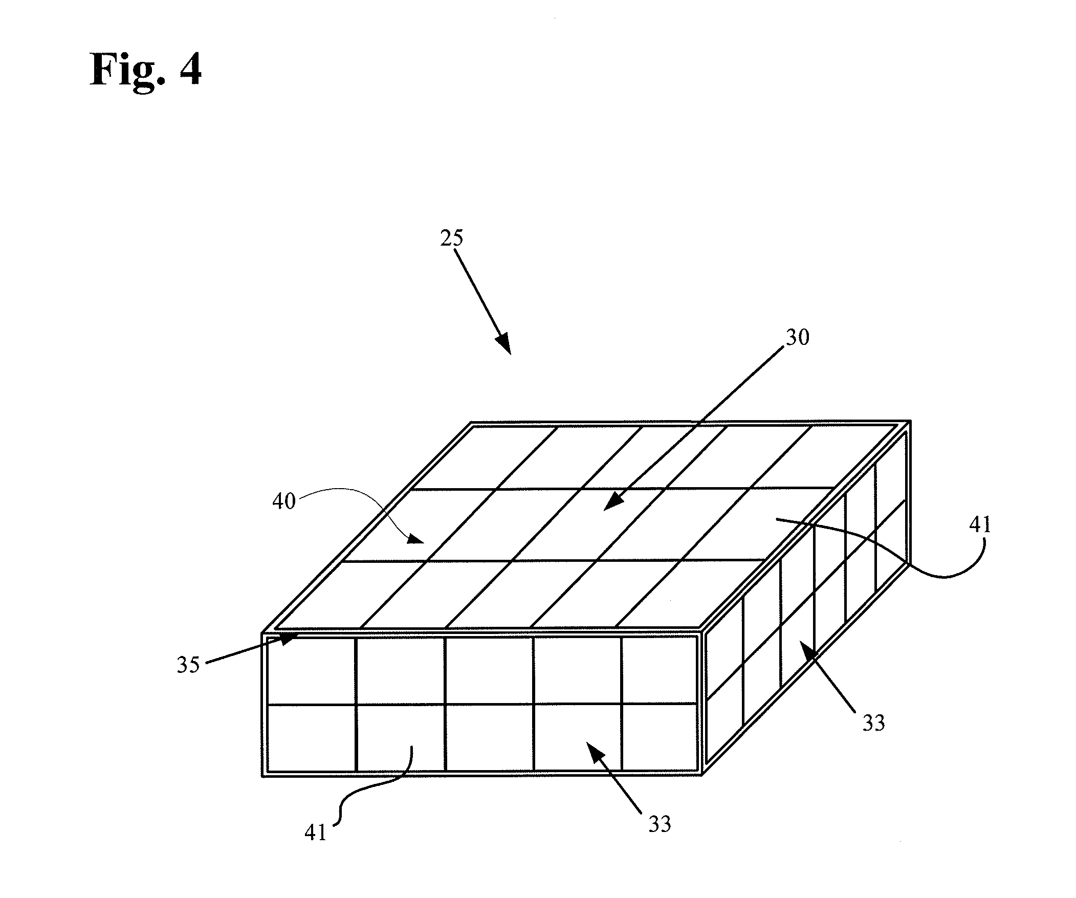
FIG. 4 is a perspective view of a receiver housing in accordance with various aspects of the invention.
FIG. 5 is a cross-sectional, schematic view of an exemplary receiver positioned in a magnetic field.
FIG. 6 is a cross-sectional, schematic view of an exemplary receiver positioned in a magnetic field, the receiver including a ferrite covering in accordance with various aspects of the invention.
FIG. 7 is a cross-sectional, schematic view of the receiver of FIG. 5, illustrating the receiver turned at an angle .theta..
FIG. 8 is a cross-sectional, schematic view of the receiver of FIG. 6, illustrating the receiver turned at an angle .theta..
FIG. 9 is a cross-sectional, schematic view of the receiver of FIG. 6, illustrating the receiver turned at an angle .theta..sub.C.
FIG. 10 is a graph illustrating efficiency of two receivers A and B at varying angles .theta., receiver A having a ferrite covering and receiver B without a ferrite covering.
FIG. 11 is a cross-sectional, schematic view of an exemplary receiver, the receiver including a continuous ferrite covering in accordance with various aspects of the invention.
DETAILED DESCRIPTION
In the description that follows, like components have been given the same reference numerals, regardless of whether they are shown in different embodiments. To illustrate an embodiment(s) of the present disclosure in a clear and concise manner, the drawings may not necessarily be to scale and certain features may be shown in somewhat schematic form. Features that are described and/or illustrated with respect to one embodiment may be used in the same way or in a similar way in one or more other embodiments and/or in combination with or instead of the features of the other embodiments.
Various aspects of the invention are similar to those described in International Patent Pub. No. WO2012045050; U.S. Pat. Nos. 8,140,168; 7,865,245; 7,774,069; 7,711,433; 7,650,187; 7,571,007; 7,741,734; 7,825,543; 6,591,139; 6,553,263; and 5,350,413; and U.S. Pub. Nos. 2010/0308939; 2008/027293; and 2010/0102639, the entire contents of which patents and applications are incorporated herein for all purposes.
Wireless Power Transmission System
Power may be transmitted wirelessly by magnetic induction. In various embodiments, the transmitter and receiver are closely coupled.
In some cases "closely coupled" or "close coupling" refers to a system that requires the coils to be very near each other in order to operate. In some cases "loosely coupled" or "loose coupling" refers to a system configured to operate when the coils have a significant spatial and/or axial separation, and in some cases up to distance equal to or less than the diameter of the larger of the coils. In some cases, "loosely coupled" or "loose coupling" refers a system that is relatively insensitive to changes in physical separation and/or orientation of the receiver and transmitter.
In various embodiments, the transmitter and receiver are non-resonant coils. For example, a change in current in one coil induces a changing magnetic field. The second coil within the magnetic field picks up the magnetic flux, which in turn induces a current in the second coil. An example of a closely coupled system with non-resonant coils is described in International Pub. No. WO2000/074747, incorporated herein for all purposes by reference. A conventional transformer is another example of a closely coupled, non-resonant system. In various embodiments, the transmitter and receiver are resonant coils. For example, one or both of the coils is connected to a tuning capacitor or other means for controlling the frequency in the respective coil. An example of closely coupled system with resonant coils is described in International Pub. Nos. WO2001/037926; WO2012/087807; WO2012/087811; WO2012/087816; WO2012/087819; WO2010/030378; and WO2012/056365, and U.S. Pub. No. 2003/0171792, incorporated herein for all purposes by reference.
In various embodiments, the transmitter and receiver are loosely coupled. For example, the transmitter can resonate to propagate magnetic flux that is picked up by the receiver at relatively great distances. In some cases energy can be transmitted over several meters. In a loosely coupled system power transfer may not necessarily depend on a critical distance. Rather, the system may be able to accommodate changes to the coupling coefficient between the transmitter and receiver. An example of a loosely coupled system is described in International Pub. No. WO2012/045050, incorporated herein for all purposes by reference.
Power may be transmitted wirelessly by radiating energy. In various embodiments, the system comprises antennas. The antennas may be resonant or non-resonant. For example, non-resonant antennas may radiate electromagnetic waves to create a field. The field can be near field or far field. The field can be directional. Generally far field has greater range but a lower power transfer rate. An example of such a system for radiating energy with resonators is described in International Pub. No. WO2010/089354, incorporated herein for all purposes by reference. An example of such a non-resonant system is described in International Pub. No. WO2009/018271, incorporated herein for all purposes by reference. Instead of antenna, the system may comprise a high energy light source such as a laser. The system can be configured so photons carry electromagnetic energy in a spatially restricted, direct, coherent path from a transmission point to a receiving point. An example of such a system is described in International Pub. No. WO2010/089354, incorporated herein for all purposes by reference.
Power may also be transmitted by taking advantage of the material or medium through which the energy passes. For example, volume conduction involves transmitting electrical energy through tissue between a transmitting point and a receiving point. An example of such a system is described in International Pub. No. WO2008/066941, incorporated herein for all purposes by reference.
Power may also be transferred using a capacitor charging technique. The system can be resonant or non-resonant. Exemplars of capacitor charging for wireless energy transfer are described in International Pub. No. WO2012/056365, incorporated herein for all purposes by reference.
The system in accordance with various aspects of the invention will now be described in connection with a system for wireless energy transfer by magnetic induction. The exemplary system utilizes resonant power transfer. The system works by transmitting power between the two inductively coupled coils. In contrast to a transformer, however, the exemplary coils are not coupled together closely. A transformer generally requires the coils to be aligned and positioned directly adjacent each other. The exemplary system accommodates looser coupling of the coils.
While described in terms of one receiver coil and one transmitter coil, one will appreciate from the description herein that the system may use two or more receiver coils and two or more transmitter coils. For example, the transmitter may be configured with two coils--a first coil to resonate flux and a second coil to excite the first coil. One will further appreciate from the description herein that usage of "resonator" and "coil" may be used somewhat interchangeably. In various respects, "resonator" refers to a coil and a capacitor connected together.
In accordance with various embodiments of this disclosure, the system comprises one or more transmitters configured to transmit power wirelessly to one or more receivers. In various embodiments, the system includes a transmitter and more than one receiver in a multiplexed arrangement. A frequency generator may be electrically coupled to the transmitter to drive the transmitter to transmit power at a particular frequency or range of frequencies. The frequency generator can include a voltage controlled oscillator and one or more switchable arrays of capacitors, a voltage controlled oscillator and one or more varactors, a phase-locked-loop, a direct digital synthesizer, or combinations thereof. The transmitter can be configured to transmit power at multiple frequencies simultaneously. The frequency generator can include two or more phase-locked-loops electrically coupled to a common reference oscillator, two or more independent voltage controlled oscillators, or combinations thereof. The transmitter can be arranged to simultaneously delivery power to multiple receivers at a common frequency.
In various embodiments, the transmitter is configured to transmit a low power signal at a particular frequency. The transmitter may transmit the low power signal for a particular time and/or interval. In various embodiments, the transmitter is configured to transmit a high power signal wirelessly at a particular frequency. The transmitter may transmit the high power signal for a particular time and/or interval.
In various embodiments, the receiver includes a frequency selection mechanism electrically coupled to the receiver coil and arranged to allow the resonator to change a frequency or a range of frequencies that the receiver can receive. The frequency selection mechanism can include a switchable array of discrete capacitors, a variable capacitance, one or more inductors electrically coupled to the receiving antenna, additional turns of a coil of the receiving antenna, or combinations thereof.
In general, most of the flux from the transmitter coil does not reach the receiver coil. The amount of flux generated by the transmitter coil that reaches the receiver coil is described by "k" and referred to as the "coupling coefficient."
In various embodiments, the system is configured to maintain a value of k in the range of between about 0.2 to about 0.01. In various embodiments, the system is configured to maintain a value of k of at least 0.01, at least 0.02, at least 0.03, at least 0.04, or at least 0.05.
In various embodiments, the coils are physically separated. In various embodiments, the separation is greater than a thickness of the receiver coil. In various embodiments, the separation distance is equal to or less than the diameter of the larger of the receiver and transmitter coil.
Because most of the flux does not reach the receiver, the transmitter coil must generate a much larger field than what is coupled to the receiver. In various embodiments, this is accomplished by configuring the transmitter with a large number of amp-turns in the coil.
Since only the flux coupled to the receiver gets coupled to a real load, most of the energy in the field is reactive. The current in the coil can be sustained with a capacitor connected to the coil to create a resonator. The power source thus only needs to supply the energy absorbed by the receiver. The resonant capacitor maintains the excess flux that is not coupled to the receiver.
In various embodiments, the impedance of the receiver is matched to the transmitter. This allows efficient transfer of energy out of the receiver. In this case the receiver coil may not need to have a resonant capacitor.
Turning now to FIG. 1, a simplified circuit for wireless energy transmission is shown. The exemplary system shows a series connection, but the system can be connected as either series or parallel on either the transmitter or receiver side.
The exemplary transmitter includes a coil Lx connected to a power source Vs by a capacitor Cx. The exemplary receiver includes a coil Ly connected to a load by a capacitor Cy. Capacitor Cx may be configured to make Lx resonate at a desired frequency. Capacitance Cx of the transmitter coil may be defined by its geometry. Inductors Lx and Ly are connected by coupling coefficient k. Mxy is the mutual inductance between the two coils. The mutual inductance, Mxy, is related to coupling coefficient, k. Mxy=k {square root over (LxLy)}
In the exemplary system the power source Vs is in series with the transmitter coil Lx so it may have to carry all the reactive current. This puts a larger burden on the current rating of the power source and any resistance in the source will add to losses.
The exemplary system includes a receiver configured to receive energy wirelessly transmitted by the transmitter. The exemplary receiver is connected to a load. The receiver and load may be connected electrically with a controllable switch.
In various embodiments, the receiver includes a circuit element configured to be connected or disconnected from the receiver coil by an electronically controllable switch. The electrical coupling can include both a serial and parallel arrangement. The circuit element can include a resistor, capacitor, inductor, lengths of an antenna structure, or combinations thereof. The system can be configured such that power is transmitted by the transmitter and can be received by the receiver in predetermined time increments.
In various embodiments, the transmitter coil and/or the receiver coil is a substantially two-dimensional structure. In various embodiments, the transmitter coil may be coupled to a transmitter impedance-matching structure. Similarly, the receiver coil may be coupled to a receiver impedance-matching structure. Examples of suitable impedance-matching structures include, but are not limited to, a coil, a loop, a transformer, and/or any impedance-matching network. An impedance-matching network may include inductors or capacitors configured to connect a signal source to the resonator structure.
In various embodiments, the transmitter is controlled by a controller (not shown) and driving circuit. The controller and/or driving circuit may include a directional coupler, a signal generator, and/or an amplifier. The controller may be configured to adjust the transmitter frequency or amplifier gain to compensate for changes to the coupling between the receiver and transmitter.
In various embodiments, the transmitter coil is connected to an impedance-matched coil loop. The loop is connected to a power source and is configured to excite the transmitter coil. The first coil loop may have finite output impedance. A signal generator output may be amplified and fed to the transmitter coil. In use power is transferred magnetically between the first coil loop and the main transmitter coil, which in turns transmits flux to the receiver. Energy received by the receiver coil is delivered by Ohmic connection to the load.
One of the challenges to a practical circuit is how to get energy in and out of the resonators. Simply putting the power source and load in series or parallel with the resonators is difficult because of the voltage and current required. In various embodiments, the system is configured to achieve an approximate energy balance by analyzing the system characteristics, estimating voltages and currents involved, and controlling circuit elements to deliver the power needed by the receiver.
In an exemplary embodiment, the system load power, P.sub.L, is assumed to be 15 Watts and the operating frequency of the system, f, is 250 kHz. Then, for each cycle the load removes a certain amount of energy from the resonance:
.times..times..times..mu..times..times..times..times..times..times..times- ..times..times..times..times..times..times..times..times..times..times. ##EQU00001## .times..times..times..mu..times..times..times..times..times..times..times- ..times..times..times..times..times..times..times..times..times..times. ##EQU00001.2##
It has been found that the energy in the receiver resonance is typically several times larger than the energy removed by the load for operative, implantable medical devices. In various embodiments, the system assumes a ratio 7:1 for energy at the receiver versus the load removed. Under this assumption, the instantaneous energy in the exemplary receiver resonance is 420 .mu.J.
The exemplary circuit was analyzed and the self inductance of the receiver coil was found to be 60 uH. From the energy and the inductance, the voltage and current in the resonator could be calculated.
.times. ##EQU00002## .times..times..times..times..times..times. ##EQU00002.2## .times..omega..times..times..times..times..times..times..times. ##EQU00002.3##
The voltage and current can be traded off against each other. The inductor may couple the same amount of flux regardless of the number of turns. The Amp-turns of the coil needs to stay the same in this example, so more turns means the current is reduced. The coil voltage, however, will need to increase. Likewise, the voltage can be reduced at the expense of a higher current. The transmitter coil needs to have much more flux. The transmitter flux is related to the receiver flux by the coupling coefficient. Accordingly, the energy in the field from the transmitter coil is scaled by k.
.times. ##EQU00003##
Given that k is 0.05:
.times..times..mu..times..times..times..times..times..times. ##EQU00004##
For the same circuit the self inductance of the transmitter coil was 146 uH as mentioned above. This results in:
.times..times..times..times..times..times. ##EQU00005## .times..omega..times..times..times..times..times..times..times. ##EQU00005.2##
One can appreciate from this example, the competing factors and how to balance voltage, current, and inductance to suit the circumstance and achieve the desired outcome. Like the receiver, the voltage and current can be traded off against each other. In this example, the voltages and currents in the system are relatively high. One can adjust the tuning to lower the voltage and/or current at the receiver if the load is lower.
Estimation of Coupling Coefficient and Mutual Inductance
As explained above, the coupling coefficient, k, may be useful for a number of reasons. In one example, the coupling coefficient can be used to understand the arrangement of the coils relative to each other so tuning adjustments can be made to ensure adequate performance. If the receiver coil moves away from the transmitter coil, the mutual inductance will decrease, and ceteris paribus, less power will be transferred. In various embodiments, the system is configured to make tuning adjustments to compensate for the drop in coupling efficiency.
The exemplary system described above often has imperfect information. For various reasons as would be understood by one of skill in the art, the system does not collect data for all parameters. Moreover, because of the physical gap between coils and without an external means of communications between the two resonators, the transmitter may have information that the receiver does not have and vice versa. These limitations make it difficult to directly measure and derive the coupling coefficient, k, in real time.
Described below are several principles for estimating the coupling coefficient, k, for two coils of a given geometry. The approaches may make use of techniques such as Biot-Savart calculations or finite element methods. Certain assumptions and generalizations, based on how the coils interact in specific orientations, are made for the sake of simplicity of understanding. From an electric circuit point of view, all the physical geometry permutations can generally lead to the coupling coefficient.
If two coils are arranged so they are in the same plane, with one coil circumscribing the other, then the coupling coefficient can be estimated to be roughly proportional to the ratio of the area of the two coils. This assumes the flux generated by coil 1 is roughly uniform over the area it encloses as shown in FIG. 2.
If the coils are out of alignment such that the coils are at a relative angle, the coupling coefficient will decrease. The amount of the decrease is estimated to be about equal to the cosine of the angle as shown in FIG. 3A. If the coils are orthogonal to each other such that theta (.theta.) is 90 degrees, the flux will not be received by the receiver and the coupling coefficient will be zero.
If the coils are arranged such that half the flux from one coil is in one direction and the other half is in the other direction, the flux cancels out and the coupling coefficient is zero, as shown in FIG. 3B.
A final principle relies on symmetry of the coils. The coupling coefficient and mutual inductance from one coil to the other is assumed to be the same regardless of which coil is being energized. M.sub.xy=M.sub.yx Wireless Power Transmission System
For reasons that will be apparent to one of skill from the description herein, even minor influences on the system from external factors can lead to significant changes in the system operation. For example, the introduction of metal to the field can significantly affect the coupling coefficient and mutual inductance.
One way to ensure the system operates effectively is to design the system without consideration of environmental factors and utilize magnetic shielding to isolate the system from external influences. For example, the computer field makes ample use of magnetic shielding to isolate sensitive components within the system.
In one embodiment, the transmitter transmits energy across a specified volume in which the receiver is positioned. The receiver typically includes components that can be negatively affected by the transmitter flux. In various embodiments, the system includes magnetic shielding to isolate the electronic components associated with the receiver coil from interference by the transmitter.
With reference generally to FIGS. 4-6, one embodiment includes a structure for two purposes--magnetically shielding components within the receiver enclosure from the transmitter and adjusting the path of the flux lines otherwise passing through the enclosure. The system can provide several advantages over existing systems. The use of a single structure for magnetic shielding and focusing and/or redirecting flux provides a simple and effective solution. The system eliminates the need for two or more structures. This is critical for implantable devices where the form factor, and reducing both the size and weight of the implant, is of utmost importance. In some cases, the elimination of redundant structures provides greater flexibility of placement, positioning, and surgical implantation procedures. The relatively simple design also reduces the cost of goods sold (COGS) and provides other technical advantages like reduced risk of failure and easier manufacturability.
FIG. 4 shows a receiver generally designated 20. The receiver 20 can be, for example, an implantable receiver of a TET system and can be configured to receive wireless power from an external transmitter of the TET system. The receiver can include a receiver coil and electronics enclosed within a housing 25. Although these components are not shown in FIG. 4, a schematic representation of the receiver circuitry can be found in FIG. 1. The housing may be hermetically sealed. The housing may be fluid tight. The receiver can include, but is not necessarily limited to, a receiver circuit, tuning circuit, signal processing circuit, power source (e.g. batteries, such as lithium-ion batteries), and controls (none of which are shown in FIG. 4). The receiver can also include a number of wire turns that may be all in one solenoidal layer or distributed over multiple layers.
The housing 25 includes an enclosure covered with a covering 40 formed of magnetically susceptible material. In an exemplary embodiment, the housing is formed of a metal and the covering is formed of ferrite. The housing may be formed of a variety of materials. The covering does not need to be formed of a purely ferrite materials. In various embodiments, the housing is covered in a ferrite-based material and/or alloy. As used herein, "ferrite" refers to materials with a significant ferrimagnetic or ferromagnetic component (percent by weight).
In one embodiment, the covering 40 of housing 25 comprises a plurality of ferrite tiles 41. One will appreciate that the housing may be only partially covered in other embodiments. The tiles may all be of a uniform size, or may be of different sizes. In the embodiment shown in FIG. 4, the tiles 41 on the top/bottom portions 30 of the housing 25 can be, for example, rectangular. The tiles 41 on the sides 33 of the housing 25 can be, alternatively, square shaped. It should be understood that any number of shape of tiles can be used to cover the housing 25. For example, a tile could be custom manufactured to precisely cover one face of the housing. Also referring to FIG. 4, there may exist small gaps 35 between the ferrite tiles 41, particularly near the edges of the housing. These gaps can be minimized or eliminating by arranging the tiles 41 on one side of the enclosure (e.g., top/bottom portion 30) so as to overlap the edges of the tiles 41 on the adjacent side of the enclosure (e.g., side 33).
The surface area of the housing that is covered may depend upon design goals and expected use. The thickness of the exemplary ferrite tiles is sufficient such that the magnetization of the ferrite is not saturated. In many implementations, the ferrite is far from saturation, and the thickness is instead chosen to be practical during manufacture, e.g., the ferrite tiles are not so thin that they could easily crack or break apart during the assembly process.
Housing 25 is intended to be wrapped with windings to form receiver 20. In various embodiments, the housing is wrapped end-to-end with Litz wires. The housing may have a plurality of turns, for example, 5 turns, 10 turns, 15 turns, 20 turns, 25 turns, or more.
FIGS. 5 and 6 illustrate use of two different receiver configurations in accordance with various aspects of the invention. FIG. 5 is a cross-sectional schematic representation of a receiver without a ferrite covering. FIG. 6 is a cross-sectional schematic representation of a receiver with a ferrite covering similar to FIG. 4.
FIG. 5 illustrates interaction of a receiver 10 with flux lines when it is introduced into a field of the transmitter (e.g., the transmitter of FIG. 1). Receiver 10 includes a housing 13 without a ferrite covering. Flux lines F1, F2, F3, and F4 are presented to receiver 20. Lines F1 and F2 pass through a front face and exit out a back face of the receiver. Lines F1 and F2 induce a good electromagnetic force (voltage) in the receiver coil. Lines F1 and F2 are said to be efficient because they are picked up by all the windings. Line F3 passes through the front face and out the sidewall. F3 is relatively efficient in that it is picked up by most of the windings. In the illustrated embodiment, for example, voltage is induced in about half the windings. Line F4 presents a more significant problem. Line F4 passes through the front face and out the front edge of sidewall such that it only passes through a small percentage of the turns. In the case of FIG. 5, line F4 induces a voltage in only one or two turns.
Turning to FIG. 6, a receiver 20 including a housing 25 a ferrite covering 40. The ferrite-covered housing can be wrapped with wires 22 in a plurality of turns.
In contrast to receiver 10 of FIG. 5, receiver 20 in FIG. 6 more efficiently translates the flux lines into an induced voltage. Receiver 20 also shields the components inside housing 25 from interference by the magnetic field lines.
Lines F1' and F2' induce a voltage in all the wires similar to the example of FIG. 5. Unlike the structure above, however, lines F3' and F4' create larger voltages in the receiving coil than similar lines F3 and F4 with receiver 10. Line F3' hits housing 25 along a front face. The magnetic properties of the material cause the energy to travel from the point of impact along the front face and sidewall and exit somewhere further past the turns. This is in contrast to the example of F3 where the line travels directly through the structure. In the example of FIG. 6, the line is picked up by most of the turns whereas without the ferrite covering shown in FIG. 5 the same line would only be picked up by about half the turns. Similarly, line F4' is picked up by a larger number of the turns than would be the case with the structure of FIG. 5. In turn, ceteris paribus, a greater voltage is created when the receiver is introduced to the same field. The structure is thus said to be more efficient. Efficiency is represented herein as (eta).
The improved efficiency of receiver 20 is more pronounced as the angle .theta. (theta) of the receiver changes relative to the transmitter. FIGS. 7 and 8 illustrate how the same flux lines are redirected using the ferrite covering to improve efficiency. FIG. 7 shows the same receiver 10 of FIG. 5 except the receiver has been rotated at an angle .theta.. In this exemplary case lines F2a, F3a, and F4a all pass through the interior of the receiver housing and out a sidewall. Thus, the efficiency is diminished for these lines and the lines also interfere with the internal components. By contrast, receiver 20 of FIG. 8 generates more voltage in the same field and reduces or eliminates interference with internal components. Lines F2a', F3a', and F4a' are all guided around the housing periphery and are transferred away from the housing further back along the windings as line F.
With the receiver 20 making use of a covering 40, the improvements in efficiency may be lost at a particular critical angle, .theta..sub.C. FIG. 9 shows receiver 20 at an angle .theta..sub.C. In the illustrated embodiment, line F3' passes through one sidewall and out another sidewall. Indeed, more lines enter the first sidewall than the front face because of the steep angle. In other words, the surface area in a plane parallel the transmitter is larger for the sidewall than the front face. At angles beyond .theta..sub.C, some field lines are redirected by the ferrite so that they are picked up by fewer turns than in a receiver without ferrite.
FIG. 10 is a graph illustrating the effect described above with respect to FIGS. 5-9. Line A illustrates data obtained using a structure similar to that of receiver 20, with a ferrite covering. Line A illustrates data obtained using a structure similar to that of receiver 10, without the covering. The graph illustrates that when the receiver and transmitter are perfectly aligned (i.e. parallel) the efficiency of receiver 20 is slightly higher. In one case the efficiency was found to be about 0.5% higher.
Moving along the curves, the efficiency of receiver 20 remains high over a far wider range of angles than receiver 10. This is shown by the flatter section of line A versus the declining slope of line B. At some angle there is an inflection point where the slope of line A rapidly changes. This effect is described above with respect to FIG. 9. Slightly beyond this angle lines A and B intersect and the structure of receiver 10 becomes more efficient.
Lines A and B approach the x-axis, theta, at different points. This shows that the efficiency of receiver 20 drops to zero at a smaller angle than receiver 10.
FIG. 11 shows a receiver 200 similar to receiver 20 except the covering is formed of a material that coats the housing. The material defines a covering 240 around a housing 225 and wrapped by wire turns 222. Covering 240 may be formed by dip coating or similar processes. The exemplary covering does not include gaps as would be present with tiles. Moreover, the covering 240 can be relatively thicker than covering 40.
One will appreciate from the description herein how to select the components to optimize performance based on a particular application. In various embodiments, the receiver can be configured to make use of the flat section of line A. For example, the receiver can be configured such that the critical angle, .theta..sub.C, is greater than the largest angle expected to be seen in practice. In this manner the receiver will operate efficiently across the entire operational range of angles. In another example, the inflection point may be used such that little or no voltage is induced beyond a certain angle. The system could recognize a sharp drop in voltage and perform an action (e.g. generate an alarm or fault code). For example, the system can send an audible or visible alarm to the user that the coils are drastically out of alignment.
One aspect of the disclosure is directed to an implantable receiver for wirelessly receiving energy from a transmitter, including a housing enclosing volume including a receiving coil and components susceptible to interference by magnetic flux; a covering around at least a portion of the housing; at least one wire wrapped around the housing to form a plurality of turns; wherein the covering is formed of a ferrite material configured to both magnetically shield a respective portion of the internal volume and redirect incoming magnetic flux.
In various embodiments, the receiver includes coil circuitry including at least two coils; and receiver circuitry configured to transmit power excited in the receiver coil in response to exposure to a field to a load. In various embodiments, the load is an implantable medical device including an operative component. The operative component may be a circulatory support device. The operative component may be a blood pump for supporting and/or replacing the function of the heart. The operative component may be a left ventricular assist device, right ventricular assist device, bi-ventricular assist device, and/or total artificial heart. All or part of the operative component may be external to the body.
In various embodiments, the covering comprises a plurality of tiles. In various embodiments, the covering covers the entire housing periphery.
Various aspects of the invention are directed to a system including a receiver, a transmitter for generating a magnetic field to the receiver, and an implantable mechanical circulatory support (MCS) device. In various embodiments, the MCS device is configured to be powered by energy from the receiver. In various embodiments, the system further includes an implantable battery. In various embodiments, the MCS device is configured to be powered by one of the receiver, the battery, or a combination thereof. In various embodiments, the system further includes an implantable controller.
Another aspect of the disclosure is directed to a method of using the system, and in particular the receiver. In various respects the disclosure is directed to wirelessly transmitting energy comprising energizing a transmitter to generate a magnetic field, and positioning the receiver in the magnetic field to induce a voltage in the receiver coil. In various embodiments, the method includes positioning the receiver in a mammalian body. In various embodiments, the method includes positioning the receiver in a patient suffering from heart failure, cardiogenic shock, or undergoing high risk surgery (e.g. percutaneous coronary intervention). In various embodiments, the method includes positioning the receiver in the chest cavity of a human.
One will appreciate from the description herein that the configuration of the covering may be modified to improve performance. For example, only a portion of the housing may be covered with ferrite material to achieve a desired efficiency-angle curve. In one example, only a portion of the housing is covered based on what part of the housing is desired to be magnetically shielded. These and many other modifications are within the spirit of the inventions.
The foregoing descriptions of specific embodiments of the present invention have been presented for purposes of illustration and description. They are not intended to be exhaustive or to limit the invention to the precise forms disclosed, and obviously many modifications and variations are possible in light of the above teaching. The embodiments were chosen and described in order to best explain the principles of the invention and its practical application, to thereby enable others skilled in the art to best utilize the invention and various embodiments with various modifications as are suited to the particular use contemplated. It is intended that the scope of the invention be defined by the Claims appended hereto and their equivalents.
* * * * *
References
D00000
D00001
D00002
D00003
D00004
D00005
D00006
D00007
D00008
D00009
D00010
M00001
M00002

M00003

M00004

M00005

XML
uspto.report is an independent third-party trademark research tool that is not affiliated, endorsed, or sponsored by the United States Patent and Trademark Office (USPTO) or any other governmental organization. The information provided by uspto.report is based on publicly available data at the time of writing and is intended for informational purposes only.
While we strive to provide accurate and up-to-date information, we do not guarantee the accuracy, completeness, reliability, or suitability of the information displayed on this site. The use of this site is at your own risk. Any reliance you place on such information is therefore strictly at your own risk.
All official trademark data, including owner information, should be verified by visiting the official USPTO website at www.uspto.gov. This site is not intended to replace professional legal advice and should not be used as a substitute for consulting with a legal professional who is knowledgeable about trademark law.