Impeller suspension mechanism for heart pump
Yanai , et al.
U.S. patent number 10,245,361 [Application Number 15/042,685] was granted by the patent office on 2019-04-02 for impeller suspension mechanism for heart pump. This patent grant is currently assigned to TC1 LLC. The grantee listed for this patent is TC1 LLC. Invention is credited to Jason Nanna, Masamichi Yanai.


View All Diagrams
| United States Patent | 10,245,361 |
| Yanai , et al. | April 2, 2019 |
Impeller suspension mechanism for heart pump
Abstract
A centrifugal blood pump includes a housing that defines an inlet passage, a chamber, and an outlet passage. The pump includes an impeller rotatably positioned in the chamber to transfer blood from the inlet passage through the chamber and to the outlet passage and magnetic members embedded in the impeller such that the impeller and the magnetic members rotate together within the chamber. The pump includes a motor to control movement of the impeller in the chamber. The motor is adjacent the chamber and separated from the chamber by a partition member. The pump includes an inner annular magnetic member and an outer annular magnetic member embedded in a side of the housing opposite the partition member. A first net magnetic force between the inner annular magnetic member and the magnetic members exhibits greater attraction than a second net magnetic force between the outer annular member and the magnetic members.
| Inventors: | Yanai; Masamichi (Ann Arbor, MI), Nanna; Jason (Ypsilanti, MI) | ||||||||||
|---|---|---|---|---|---|---|---|---|---|---|---|
| Applicant: |
|
||||||||||
| Assignee: | TC1 LLC (Pleasanton,
CA) |
||||||||||
| Family ID: | 56614899 | ||||||||||
| Appl. No.: | 15/042,685 | ||||||||||
| Filed: | February 12, 2016 |
Prior Publication Data
| Document Identifier | Publication Date | |
|---|---|---|
| US 20160235900 A1 | Aug 18, 2016 | |
Related U.S. Patent Documents
| Application Number | Filing Date | Patent Number | Issue Date | ||
|---|---|---|---|---|---|
| 62115741 | Feb 13, 2015 | ||||
| Current U.S. Class: | 1/1 |
| Current CPC Class: | A61M 1/1036 (20140204); A61M 1/1015 (20140204); A61M 1/1017 (20140204); F04D 29/048 (20130101); F04D 13/0666 (20130101); F04D 29/047 (20130101); F04D 13/064 (20130101); A61M 1/1086 (20130101); A61M 1/1031 (20140204); A61M 1/101 (20130101); A61M 1/122 (20140204) |
| Current International Class: | A61N 1/362 (20060101); A61M 1/10 (20060101); F04D 13/06 (20060101); F04D 29/047 (20060101); F04D 29/048 (20060101); A61M 1/12 (20060101) |
References Cited [Referenced By]
U.S. Patent Documents
| 1093868 | April 1914 | Leighty |
| 2684035 | July 1954 | Kemp |
| 3023334 | February 1962 | Burr et al. |
| 3510229 | May 1970 | Smith |
| 3620638 | November 1971 | Kaye et al. |
| 3870382 | March 1975 | Reinhoudt |
| 3932069 | January 1976 | Giardini et al. |
| 3960468 | June 1976 | Boorse et al. |
| 4149535 | April 1979 | Voider |
| 4382199 | May 1983 | Isaacson |
| 4392836 | June 1983 | Sugawara |
| 4434389 | February 1984 | Langley et al. |
| 4507048 | March 1985 | Belenger et al. |
| 4528485 | July 1985 | Boyd, Jr. |
| 4540402 | September 1985 | Aigner |
| 4549860 | October 1985 | Yakich |
| 4645961 | February 1987 | Maisky |
| 4686982 | August 1987 | Nash |
| 4688998 | August 1987 | Olsen et al. |
| 4753221 | June 1988 | Kensey et al. |
| 4769006 | September 1988 | Papatonakos |
| 4779614 | October 1988 | Moise |
| 4790843 | December 1988 | Carpentier et al. |
| 4806080 | February 1989 | Mizobuchi et al. |
| 4817586 | April 1989 | Wampler |
| 4846152 | July 1989 | Wampler et al. |
| 4857781 | August 1989 | Shih |
| 4888011 | December 1989 | Kung et al. |
| 4895557 | January 1990 | Moise et al. |
| 4900227 | February 1990 | Troup lin |
| 4902272 | February 1990 | Milder et al. |
| 4906229 | March 1990 | Wampler |
| 4908012 | March 1990 | Moise et al. |
| 4919647 | April 1990 | Nash |
| 4930997 | June 1990 | Bennett |
| 4944722 | July 1990 | Carriker et al. |
| 4957504 | September 1990 | Chardack |
| 4964864 | October 1990 | Summers et al. |
| 4969865 | November 1990 | Hwang et al. |
| 4985014 | January 1991 | Orejola |
| 4995857 | February 1991 | Arnold |
| 5021048 | June 1991 | Buckholtz |
| 5078741 | January 1992 | Bramm et al. |
| 5092844 | March 1992 | Schwartz et al. |
| 5092879 | March 1992 | Jarvik |
| 5100374 | March 1992 | Kageyama |
| 5106263 | April 1992 | Irie |
| 5106273 | April 1992 | Lemarquand et al. |
| 5106372 | April 1992 | Ranford |
| 5112202 | May 1992 | Ozaki et al. |
| 5129883 | July 1992 | Black |
| 5145333 | September 1992 | Smith |
| 5147186 | September 1992 | Buckholtz |
| 5112349 | December 1992 | Summers et al. |
| 5190528 | February 1993 | Fonger et al. |
| 5201679 | April 1993 | Velte et al. |
| 5211546 | May 1993 | Isaacson et al. |
| 5229693 | July 1993 | Futami et al. |
| 5275580 | January 1994 | Yamazaki |
| 5290227 | January 1994 | Pasque |
| 5360445 | January 1994 | Goldowsky |
| 5290236 | March 1994 | Mathewson |
| 5300112 | April 1994 | Barr |
| 5306295 | April 1994 | Kolff et al. |
| 5312341 | May 1994 | Turi |
| 5313128 | May 1994 | Robinson et al. |
| 5332374 | July 1994 | Kricker et al. |
| 5346458 | September 1994 | Afield |
| 5350283 | September 1994 | Nakazeki et al. |
| 5354331 | November 1994 | Schachar |
| 5370509 | December 1994 | Golding et al. |
| 5376114 | December 1994 | Jarvik |
| 5385581 | January 1995 | Bramm et al. |
| 5405383 | November 1995 | Barr |
| 5449342 | December 1995 | Hirose et al. |
| 5478222 | December 1995 | Heidelberg et al. |
| 5504978 | April 1996 | Meyer, III |
| 5507629 | April 1996 | Jarvik |
| 5519270 | May 1996 | Yamada et al. |
| 5533957 | September 1996 | Aldea |
| 5569111 | October 1996 | Cho et al. |
| 5575630 | November 1996 | Nakazawa et al. |
| 5588812 | December 1996 | Taylor et al. |
| 5595762 | January 1997 | Derrieu et al. |
| 5611679 | March 1997 | Ghosh et al. |
| 5613935 | March 1997 | Jarvik |
| 5643226 | July 1997 | Cosgrove et al. |
| 5678306 | October 1997 | Bozeman, Jr. et al. |
| 5692882 | December 1997 | Bozeman, Jr. et al. |
| 5695471 | December 1997 | Wampler |
| 5708346 | January 1998 | Schob |
| 5725357 | March 1998 | Nakazeki et al. |
| 5738649 | April 1998 | Macoviak |
| 5746575 | May 1998 | Westphal et al. |
| 5746709 | May 1998 | Rom et al. |
| 5755784 | May 1998 | Jarvik |
| 5776111 | July 1998 | Tesio |
| 5795074 | August 1998 | Rahman et al. |
| 5800559 | September 1998 | Higham et al. |
| 5807311 | September 1998 | Palestrant |
| 5814011 | September 1998 | Corace |
| 5824069 | October 1998 | Lemole |
| 5749855 | December 1998 | Reitan |
| 5843129 | December 1998 | Larson et al. |
| 5851174 | December 1998 | Jarvik et al. |
| 5853394 | December 1998 | Tolkoff et al. |
| 5890883 | April 1999 | Golding et al. |
| 5911685 | June 1999 | Siess et al. |
| 5917295 | June 1999 | Mongeau |
| 5917297 | June 1999 | Gerster et al. |
| 5921913 | July 1999 | Siess |
| 5924848 | July 1999 | Izraelev |
| 5924975 | July 1999 | Goldowsky |
| 5928131 | July 1999 | Prem |
| 5938412 | August 1999 | Israelev |
| 5941813 | August 1999 | Sievers et al. |
| 5945753 | August 1999 | Maegawa et al. |
| 5868702 | September 1999 | Stevens et al. |
| 5868703 | September 1999 | Bertolero et al. |
| 5947703 | September 1999 | Nojiri et al. |
| 5951263 | September 1999 | Taylor et al. |
| 5984892 | November 1999 | Bedingham |
| 5964694 | December 1999 | Siess et al. |
| 6004269 | December 1999 | Crowley et al. |
| 6007479 | December 1999 | Rottenberg et al. |
| 6030188 | February 2000 | Nojiri et al. |
| 6042347 | March 2000 | Scholl et al. |
| 6053705 | April 2000 | Schob et al. |
| 6066086 | May 2000 | Antaki et al. |
| 6071093 | June 2000 | Hart |
| 6074180 | June 2000 | Khanwilkar et al. |
| 6080133 | June 2000 | Wampler |
| 6082900 | July 2000 | Takeuchi et al. |
| 6083260 | July 2000 | Aboul-Hosn et al. |
| 6100618 | August 2000 | Schoeb et al. |
| 6058593 | September 2000 | Siess |
| 6123659 | September 2000 | leBlanc et al. |
| 6123726 | September 2000 | Mori et al. |
| 6139487 | October 2000 | Siess |
| 6086527 | November 2000 | Talpade |
| 6142752 | November 2000 | Akamatsu et al. |
| 6143025 | November 2000 | Stobie et al. |
| 6146325 | November 2000 | Lewis et al. |
| 6149683 | November 2000 | Lancisi et al. |
| 6158984 | December 2000 | Cao et al. |
| 6171078 | January 2001 | Schob |
| 6176822 | January 2001 | Nix et al. |
| 6176848 | January 2001 | Rau et al. |
| 6179773 | January 2001 | Prem et al. |
| 6190304 | February 2001 | Downey et al. |
| 6200260 | March 2001 | Bolling |
| 6206659 | March 2001 | Izraelev |
| 6254359 | March 2001 | Aber |
| 6222290 | April 2001 | Schob et al. |
| 6227797 | May 2001 | Watterson |
| 6227820 | May 2001 | Jarvik |
| 6234772 | May 2001 | Wampler et al. |
| 6234998 | May 2001 | Wampler |
| 6247892 | June 2001 | Kazatchkov et al. |
| 6249067 | June 2001 | Schob et al. |
| 6264635 | July 2001 | Wampler et al. |
| 6268675 | July 2001 | Amrhein |
| 6276831 | August 2001 | Takahashi et al. |
| 6293901 | September 2001 | Prem |
| 6295877 | October 2001 | Aboul-Hosn et al. |
| 6319231 | November 2001 | Andrulitis |
| 6320731 | November 2001 | Eeaves et al. |
| 6245007 | December 2001 | Bedingham et al. |
| 6351048 | February 2002 | Schob et al. |
| 6355998 | March 2002 | Schob et al. |
| 6365996 | April 2002 | Schob |
| 6375607 | April 2002 | Prem |
| 6387037 | May 2002 | Bolling et al. |
| 6394769 | May 2002 | Bearnson et al. |
| 6422990 | July 2002 | Prem |
| 6425007 | July 2002 | Messinger |
| 6428464 | August 2002 | Bolling |
| 6439845 | August 2002 | Veres |
| 6447266 | September 2002 | Antaki et al. |
| 6447441 | September 2002 | Yu et al. |
| 6458163 | October 2002 | Slemker et al. |
| 6508777 | January 2003 | Macoviak et al. |
| 6508787 | January 2003 | Erbel et al. |
| 6517315 | February 2003 | Belady |
| 6522093 | February 2003 | Hsu et al. |
| 6532964 | March 2003 | Aboul-Hosn et al. |
| 6533716 | March 2003 | Schmitz-Rode et al. |
| 6544216 | April 2003 | Sammler et al. |
| 6547519 | April 2003 | deBlanc et al. |
| 6547530 | April 2003 | Ozaki et al. |
| 6575717 | June 2003 | Ozaki et al. |
| 6589030 | July 2003 | Ozaki |
| 6595762 | July 2003 | Khanwilkar et al. |
| 6605032 | August 2003 | Benkowski et al. |
| 6609883 | August 2003 | Woodard et al. |
| 6610004 | August 2003 | Viole et al. |
| 6623420 | September 2003 | Reich et al. |
| 6641378 | November 2003 | Davis et al. |
| 6641558 | November 2003 | Aboul-Hosn et al. |
| 6688861 | February 2004 | Wampler |
| 6692318 | February 2004 | McBride |
| 6698097 | March 2004 | Miura et al. |
| 6709418 | March 2004 | Aboul-Hosn et al. |
| 6716157 | April 2004 | Goldowsky |
| 6716189 | April 2004 | Jarvik et al. |
| 6732501 | May 2004 | Yu et al. |
| 6749598 | June 2004 | Keren et al. |
| 6776578 | August 2004 | Belady |
| 6790171 | September 2004 | Griindeman et al. |
| 6794789 | September 2004 | Siess et al. |
| 6808371 | October 2004 | Niwatsukino et al. |
| 6817836 | November 2004 | Nose et al. |
| 6846168 | January 2005 | Davis et al. |
| 6860713 | January 2005 | Hoover |
| 6884210 | April 2005 | Nose et al. |
| 6935344 | August 2005 | Aboul-Hosn et al. |
| 6926662 | September 2005 | Aboul-Hosn et al. |
| 6942672 | September 2005 | Heilman et al. |
| 6949066 | September 2005 | Beamson et al. |
| 6966748 | November 2005 | Woodard et al. |
| 6974436 | December 2005 | Aboul-Hosn et al. |
| 6991595 | January 2006 | Burke et al. |
| 7010954 | March 2006 | Siess et al. |
| 7011620 | March 2006 | Siess |
| 7022100 | April 2006 | Aboul-Hosn et al. |
| 7048681 | May 2006 | Tsubouchi et al. |
| 7089059 | August 2006 | Pless |
| 7090401 | August 2006 | Rahman et al. |
| 7112903 | September 2006 | Schob |
| 7122019 | October 2006 | Kesten et al. |
| 7128538 | October 2006 | Tsubouchi et al. |
| 7027875 | November 2006 | Siess et al. |
| 7156802 | January 2007 | Woodard et al. |
| 7160243 | January 2007 | Medvedev |
| 7175588 | February 2007 | Morello |
| 7202582 | April 2007 | Eckert et al. |
| 7172551 | June 2007 | Leasure |
| 7241257 | October 2007 | Ainsworth et al. |
| 7284956 | October 2007 | Nose et al. |
| 7331921 | February 2008 | Viole et al. |
| 7335192 | February 2008 | Keren et al. |
| 7393181 | July 2008 | McBride et al. |
| 7431688 | October 2008 | Wampler et al. |
| 7329236 | December 2008 | Kesten et al. |
| 7462019 | December 2008 | Allarie et al. |
| 7467930 | December 2008 | Ozaki et al. |
| 7470246 | December 2008 | Mori et al. |
| 7476077 | January 2009 | Woodard et al. |
| 7491163 | February 2009 | Viole et al. |
| 7575423 | August 2009 | Wampler |
| 7645225 | January 2010 | Medvedev et al. |
| 7660635 | February 2010 | Verness et al. |
| 7699586 | April 2010 | LaRose et al. |
| 7748964 | July 2010 | Yaegashi et al. |
| 7731675 | August 2010 | Aboul-Hosn et al. |
| 7802966 | September 2010 | Wampler et al. |
| 7841976 | November 2010 | McBride et al. |
| 7862501 | January 2011 | Woodard |
| 7888242 | February 2011 | Tanaka et al. |
| 7934909 | May 2011 | Nuesser et al. |
| 7972122 | July 2011 | LaRose et al. |
| 7976271 | July 2011 | LaRose et al. |
| 7997854 | August 2011 | LaRose et al. |
| 8007254 | August 2011 | LaRose et al. |
| 8096935 | January 2012 | Sutton et al. |
| 8123669 | February 2012 | Siess et al. |
| 8152493 | April 2012 | LaRose et al. |
| 8177703 | May 2012 | Smith et al. |
| 8226373 | July 2012 | Yaehashi |
| 8282359 | October 2012 | Ayre et al. |
| 8283829 | October 2012 | Yamamoto et al. |
| 8366381 | February 2013 | Woodard et al. |
| 8403823 | March 2013 | Yu et al. |
| 8512012 | August 2013 | Mustafa et al. |
| 8535211 | September 2013 | Campbell et al. |
| 8585290 | November 2013 | Bauer |
| 8686674 | April 2014 | Bi et al. |
| 8770945 | July 2014 | Ozaki et al. |
| 8821365 | September 2014 | Ozaki et al. |
| 8827661 | September 2014 | Mori |
| 8652024 | October 2014 | Yanai et al. |
| 8864644 | October 2014 | Yomtov |
| 8870552 | October 2014 | Ayre et al. |
| 8968174 | March 2015 | Yanai et al. |
| 9039595 | May 2015 | Ayre et al. |
| 9067005 | June 2015 | Ozaki et al. |
| 9068572 | June 2015 | Ozaki et al. |
| 9109601 | August 2015 | Mori |
| 9132215 | September 2015 | Ozaki et al. |
| 9133854 | September 2015 | Okawa et al. |
| 9371826 | June 2016 | Yanai et al. |
| 9381285 | July 2016 | Ozaki et al. |
| 9382908 | July 2016 | Ozaki et al. |
| 9410549 | August 2016 | Ozaki et al. |
| 9556873 | January 2017 | Yanai et al. |
| 2001/0039369 | November 2001 | Terentiev |
| 2002/0051711 | May 2002 | Ozaki |
| 2002/0058994 | May 2002 | Hill et al. |
| 2002/0094281 | July 2002 | Khanwilkar et al. |
| 2002/0095210 | July 2002 | Finnegan et al. |
| 2003/0023302 | January 2003 | Moe et al. |
| 2003/0045772 | March 2003 | Reich et al. |
| 2003/0072656 | April 2003 | Niwatsukino et al. |
| 2003/0144574 | July 2003 | Heilman et al. |
| 2003/0199727 | October 2003 | Burke et al. |
| 2003/0236488 | December 2003 | Novak |
| 2003/0236490 | December 2003 | Novak |
| 2004/0007515 | January 2004 | Geyer |
| 2004/0015232 | January 2004 | Shu et al. |
| 2004/0024285 | February 2004 | Muckter |
| 2004/0030381 | February 2004 | Shu |
| 2004/0064012 | April 2004 | Yanai |
| 2004/0143151 | July 2004 | Mori et al. |
| 2004/0145337 | July 2004 | Morishita |
| 2004/0152944 | August 2004 | Medvedev et al. |
| 2004/0171905 | September 2004 | Yu et al. |
| 2004/0210305 | October 2004 | Shu et al. |
| 2004/0215050 | October 2004 | Morello |
| 2004/0263341 | December 2004 | Enzinna |
| 2005/0004418 | January 2005 | Morello |
| 2005/0008496 | January 2005 | Tsubouchi et al. |
| 2005/0025630 | February 2005 | Ayre et al. |
| 2005/0043665 | February 2005 | Vinci et al. |
| 2005/0073273 | April 2005 | Maslov et al. |
| 2005/0089422 | April 2005 | Ozaki et al. |
| 2005/0131271 | June 2005 | Benkowski et al. |
| 2005/0141887 | June 2005 | Lelkes |
| 2005/0194851 | September 2005 | Eckert et al. |
| 2005/0261542 | November 2005 | Abe et al. |
| 2005/0287022 | December 2005 | Yaegashi et al. |
| 2006/0024182 | February 2006 | Akdis et al. |
| 2006/0055274 | March 2006 | Kim |
| 2006/0127227 | June 2006 | Mehlhorn et al. |
| 2007/0073393 | March 2007 | Kung et al. |
| 2007/0078293 | April 2007 | Shambaugh, Jr. |
| 2007/0095648 | May 2007 | May et al. |
| 2007/0114961 | May 2007 | Schwarzkopf |
| 2007/0134993 | June 2007 | Tamez et al. |
| 2007/0189648 | August 2007 | Kita et al. |
| 2007/0213690 | September 2007 | Phillips et al. |
| 2007/0231135 | October 2007 | Wampler et al. |
| 2007/0282298 | December 2007 | Mason |
| 2007/0297923 | December 2007 | Tada |
| 2008/0007196 | January 2008 | Tan et al. |
| 2008/0021394 | January 2008 | La Rose et al. |
| 2008/0030895 | February 2008 | Obara et al. |
| 2008/0119777 | May 2008 | Vinci et al. |
| 2008/0124231 | May 2008 | Yaegashi |
| 2008/0183287 | July 2008 | Ayre |
| 2008/0211439 | September 2008 | Yokota et al. |
| 2008/0281146 | November 2008 | Morello |
| 2009/0041595 | February 2009 | Garzaniti et al. |
| 2009/0060743 | March 2009 | McBride et al. |
| 2009/0074336 | March 2009 | Engesser et al. |
| 2009/0099406 | April 2009 | Salmonsen et al. |
| 2009/0171136 | July 2009 | Shambaugh, Jr. |
| 2009/0257693 | October 2009 | Aiello |
| 2009/0318834 | December 2009 | Fujiwara et al. |
| 2010/0168534 | July 2010 | Matsumoto et al. |
| 2010/0185280 | July 2010 | Ayre et al. |
| 2010/0222634 | September 2010 | Poirier |
| 2010/0234835 | September 2010 | Horikawa et al. |
| 2010/0256440 | October 2010 | Maher |
| 2010/0262039 | October 2010 | Fujiwara et al. |
| 2010/0266423 | October 2010 | Gohean et al. |
| 2010/0305692 | December 2010 | Thomas et al. |
| 2010/0324465 | December 2010 | Vinci et al. |
| 2011/0015732 | January 2011 | Kanebako |
| 2011/0112354 | May 2011 | Nishimura et al. |
| 2011/0118766 | May 2011 | Reichenbach et al. |
| 2011/0118829 | May 2011 | Hoarau et al. |
| 2011/0118833 | May 2011 | Reichenbach et al. |
| 2011/0129373 | June 2011 | Mori |
| 2011/0160519 | June 2011 | Arndt et al. |
| 2011/0218383 | September 2011 | Broen et al. |
| 2011/0218384 | September 2011 | Bachman et al. |
| 2011/0218385 | September 2011 | Bolyare et al. |
| 2011/0237978 | September 2011 | Fujiwara et al. |
| 2011/0243759 | October 2011 | Ozaki et al. |
| 2011/0318203 | December 2011 | Ozaki et al. |
| 2012/0003108 | January 2012 | Ozaki et al. |
| 2012/0016178 | January 2012 | Woodard et al. |
| 2012/0022645 | January 2012 | Burke |
| 2012/0035411 | February 2012 | LaRose et al. |
| 2012/0078030 | March 2012 | Bourque |
| 2012/0078031 | March 2012 | Burke et al. |
| 2012/0095281 | April 2012 | Reichenbach et al. |
| 2012/0130152 | May 2012 | Ozaki et al. |
| 2012/0226350 | September 2012 | Ruder et al. |
| 2012/0243759 | September 2012 | Fujisawa |
| 2012/0245681 | September 2012 | Casas et al. |
| 2012/0253103 | October 2012 | Jarvik |
| 2012/0308363 | December 2012 | Ozaki et al. |
| 2013/0030240 | January 2013 | Schima et al. |
| 2013/0121821 | May 2013 | Ozaki et al. |
| 2013/0158521 | June 2013 | Sobue |
| 2013/0170970 | July 2013 | Ozaki et al. |
| 2013/0178694 | July 2013 | Jeffery et al. |
| 2013/0225909 | August 2013 | Dormanen et al. |
| 2013/0243623 | September 2013 | Okawa et al. |
| 2013/0289334 | October 2013 | Badstibner et al. |
| 2013/0331711 | December 2013 | Mathur et al. |
| 2014/0030122 | January 2014 | Ozaki et al. |
| 2014/0066690 | March 2014 | Siebenhaar et al. |
| 2014/0066691 | March 2014 | Siebenhaar |
| 2014/0100413 | April 2014 | Casas et al. |
| 2014/0107399 | April 2014 | Spence |
| 2014/0142367 | May 2014 | Ayre et al. |
| 2014/0155682 | June 2014 | Jeffery et al. |
| 2014/0200389 | July 2014 | Yanai et al. |
| 2014/0205467 | July 2014 | Yanai et al. |
| 2014/0241904 | August 2014 | Yanai et al. |
| 2014/0275721 | September 2014 | Yanai et al. |
| 2014/0275727 | September 2014 | Bonde et al. |
| 2014/0296615 | October 2014 | Franano |
| 2014/0309481 | October 2014 | Medvedev et al. |
| 2014/0314597 | October 2014 | Allaire et al. |
| 2014/0323796 | October 2014 | Medvedev et al. |
| 2014/0343352 | November 2014 | Ardt et al. |
| 2015/0017030 | January 2015 | Ozaki et al. |
| 2015/0023803 | January 2015 | Fritz et al. |
| 2015/0078936 | March 2015 | Mori |
| 2015/0306290 | October 2015 | Rosenberg et al. |
| 2015/0367048 | December 2015 | Brown et al. |
| 2015/0374892 | December 2015 | Yanai et al. |
| 2016/0058929 | March 2016 | Medvedev et al. |
| 2016/0058930 | March 2016 | Medvedev et al. |
| 2016/0228628 | August 2016 | Medvedev et al. |
| 2016/0235898 | August 2016 | Yanai et al. |
| 2016/0235899 | August 2016 | Yu et al. |
| 2016/0281720 | September 2016 | Yanai et al. |
| 2016/0281728 | September 2016 | Ozaki et al. |
| 1347585 | May 2002 | CN | |||
| 1462344 | Dec 2003 | CN | |||
| 102239334 | Nov 2011 | CN | |||
| 102341600 | Feb 2012 | CN | |||
| 2945662 | Sep 1999 | EP | |||
| 971212 | Jan 2000 | EP | |||
| 1113117 | Jul 2001 | EP | |||
| 1327455 | Jul 2003 | EP | |||
| 1430919 | Jun 2004 | EP | |||
| 1598087 | Mar 2005 | EP | |||
| 1526286 | Apr 2005 | EP | |||
| 1495773 | Nov 2006 | EP | |||
| 2292282 | Mar 2011 | EP | |||
| 2298375 | Mar 2011 | EP | |||
| 2372160 | Oct 2011 | EP | |||
| 2405140 | Jan 2012 | EP | |||
| 2405141 | Jan 2012 | EP | |||
| 2461465 | Jun 2012 | EP | |||
| 2538086 | Dec 2012 | EP | |||
| 2554191 | Feb 2013 | EP | |||
| 2594799 | May 2013 | EP | |||
| 2618001 | Jul 2013 | EP | |||
| 2693609 | Feb 2014 | EP | |||
| 2948202 | Dec 2015 | EP | |||
| 2961987 | Jan 2016 | EP | |||
| 3013385 | May 2016 | EP | |||
| 58/9535 | Jan 1983 | JP | |||
| 61/293146 | Dec 1986 | JP | |||
| H02-007780 | Jan 1990 | JP | |||
| H02-033590 | Mar 1990 | JP | |||
| 04/091396 | Mar 1992 | JP | |||
| 04/148094 | May 1992 | JP | |||
| 05/021197 | Mar 1993 | JP | |||
| 06/014538 | Feb 1994 | JP | |||
| 06/053790 | Jul 1994 | JP | |||
| 2006/070476 | Sep 1994 | JP | |||
| 2006/245455 | Sep 1994 | JP | |||
| 07/014220 | Mar 1995 | JP | |||
| 07/042869 | Aug 1995 | JP | |||
| 07/509156 | Oct 1995 | JP | |||
| 09/122228 | May 1997 | JP | |||
| 10/331841 | Dec 1998 | JP | |||
| 11/244377 | Sep 1999 | JP | |||
| 2001/309628 | Nov 2001 | JP | |||
| 2003/135592 | May 2003 | JP | |||
| 2004/166401 | Jun 2004 | JP | |||
| 2004/209240 | Jul 2004 | JP | |||
| 2004/332566 | Nov 2004 | JP | |||
| 2004/346925 | Dec 2004 | JP | |||
| 2005/094955 | Apr 2005 | JP | |||
| 2005/127222 | May 2005 | JP | |||
| 2005/245138 | Sep 2005 | JP | |||
| 2005/270345 | Oct 2005 | JP | |||
| 2005/270415 | Oct 2005 | JP | |||
| 2005/287599 | Oct 2005 | JP | |||
| 2007/002885 | Jan 2007 | JP | |||
| 2007/043821 | Feb 2007 | JP | |||
| 2007/089972 | Apr 2007 | JP | |||
| 2007/089974 | Apr 2007 | JP | |||
| 2007/215292 | Aug 2007 | JP | |||
| 2007/247489 | Sep 2007 | JP | |||
| 2008/011611 | Jan 2008 | JP | |||
| 2008/104278 | May 2008 | JP | |||
| 2008/132131 | Jun 2008 | JP | |||
| 2008/99453 | Aug 2008 | JP | |||
| 2008/193838 | Aug 2008 | JP | |||
| 2008/297997 | Dec 2008 | JP | |||
| 2008/301634 | Dec 2008 | JP | |||
| 2006/167173 | Jun 2009 | JP | |||
| 2006/254619 | Sep 2009 | JP | |||
| 2010/133381 | Jun 2010 | JP | |||
| 2010/136863 | Jun 2010 | JP | |||
| 2010/203398 | Sep 2010 | JP | |||
| 2010/209691 | Sep 2010 | JP | |||
| 2011/169166 | Sep 2011 | JP | |||
| 2012/021413 | Feb 2012 | JP | |||
| 2012/062790 | Mar 2012 | JP | |||
| 5171953 | Mar 2013 | JP | |||
| 5572832 | Aug 2014 | JP | |||
| 5656835 | Jan 2015 | JP | |||
| 1993/07388 | Apr 1993 | WO | |||
| 94/14226 | Jun 1994 | WO | |||
| 1996/31934 | Oct 1996 | WO | |||
| 1997/42413 | Nov 1997 | WO | |||
| 2000/64509 | Nov 2000 | WO | |||
| 2004/098677 | Nov 2004 | WO | |||
| 2005/011087 | Feb 2005 | WO | |||
| 2005/028000 | Mar 2005 | WO | |||
| 2005/034312 | Apr 2005 | WO | |||
| 2009/157408 | Dec 2009 | WO | |||
| 2010/067682 | Jun 2010 | WO | |||
| 2010/101082 | Sep 2010 | WO | |||
| 2010/101107 | Sep 2010 | WO | |||
| 2011/013483 | Feb 2011 | WO | |||
| 2012/036059 | Mar 2012 | WO | |||
| 2012/040544 | Mar 2012 | WO | |||
| 2012/047550 | Apr 2012 | WO | |||
| 2012/132850 | Oct 2012 | WO | |||
| 2014/113533 | Jul 2014 | WO | |||
| 2014/116676 | Jul 2014 | WO | |||
| 2014/133942 | Sep 2014 | WO | |||
| 2014/179271 | Nov 2014 | WO | |||
| 2016/033131 | Mar 2016 | WO | |||
| 2016/033133 | Mar 2016 | WO | |||
| 2016/130846 | Aug 2016 | WO | |||
| 2016/130944 | Aug 2016 | WO | |||
| 2016/130955 | Aug 2016 | WO | |||
Other References
|
European office action dated Oct. 31, 2016 for EP 10804230.0, all pages. cited by applicant . European Office Action issued in Application No. EP 11825062 dated Jul. 19, 2016, all pages. cited by applicant . Gieras, et al., "Advancements in Electric Machines", Nov. 14, 2008, pp. 43-48. cited by applicant . International Search Report and Written Opinion of PCT/US2016/062284, dated Feb. 24, 2017, all pages. cited by applicant . European office action dated Jul. 22, 2016 for European Patent Application No. EP 09770118.9, all pages. cited by applicant . European office action dated Sep. 8, 2016 for EP 14741174, all pages. cited by applicant . Extended European Search Report for EP 14 74 3371 dated Sep. 29, 2016, all pages. cited by applicant . International Search Report and Written Opinion of PCT/US2016/017812 dated Jun. 7, 2016, all pages. cited by applicant . International Search Report and Written Opinion of PCT/US2016/017864, dated Jun. 8, 2016, all pages. cited by applicant . Decision to Grant for JP 2013-507344 dated Jun. 14, 2016, all pages. cited by applicant . International Search Report and Written Opinion of PCT/US2015/046844, dated Oct. 27, 2015, all pages. cited by applicant . International Search Report and Written Opinion of PCT/US2015/046846, dated Oct. 27, 2015, all pages. cited by applicant . European office action dated Jan. 27, 2016 for EP 10804230.0, all pages. cited by applicant . Extended European Search Report dated Feb. 4, 2016 in European Patent Application No. EP 12764433.4, filed Mar. 12, 2012, all pages. cited by applicant . International Preliminary Report on Patentability dated Jul. 30, 2015 for International Patent Application No. PCT/US2014/011786, filed on Jan. 16, 2014, all pages. cited by applicant . International Search Report and Written Opinion of PCT/US2014/012511, dated May 147, 2014, all pages. cited by applicant . International Search Report and Written Opinion of PCT/US2014/017932, dated Jun. 16, 2014, all pages. cited by applicant . International Preliminary Report on Patentability dated Sep. 11, 2015 for International Patent Application No. PCT/US2014/017932, filed on Feb. 24, 2014, all pages. cited by applicant . International Search Report and Written Opinion of PCT/US2014/035798, dated Feb. 11, 2016, all pages. cited by applicant . International Search Report and Written Opinion of PCT/US2016/017611, dated May 16, 2016, all pages. cited by applicant . International Search Report and Written Opinion of PCT/US2016/017791, dated May 16, 2016, all pages. cited by applicant . Japanese office action dated Dec. 8, 2015 JP 2013-507344, all pages. cited by applicant . Asama, J., et al., "A Compact Highly Efficient and Low Hemolytic Centrifugal Blood Pump With a Magnetically Levitated Impeller", Artificial Organs, vol. 30, No. 3, Mar. 1, 2006 (Mar. 1, 2006), pp. 160-167. cited by applicant . Asama, J., et al.,"A New Design for a Compact Centrifugal Blood Pump with a Magnetically Levitated Rotor", Asaio Jopurnal, vol. 50, No. 6, Nov. 1, 2004 (Nov. 1, 2004), pp. 550-556. cited by applicant . Asama, et al., "Suspension Performance of a Two-Axis Actively Regulated Consequent-Pole Bearingless Motor," IEEE Transactions on Energy Conversion, vol. 28, No. 4, Dec. 2013, 8 pages. cited by applicant . European Search report Issued in European Patent Application No. 10748702.7, dated Apr. 2, 2013. cited by applicant . Extended European Search Report issued in European Patent Application No. EP 10748677.1, dated Nov. 19, 2012. cited by applicant . Extended European Search Report issued in European Patent Application No. EP 11825062.0, dated Jun. 18, 2015, all pages. cited by applicant . Extended European Search Report issued in European Patent Application No. EP 11806627.3, dated Oct. 8, 2014, all pages. cited by applicant . Extended European Search Report dated Mar. 26, 2015 in European Patent Application No. EP 09770118.9 filed Jun. 22, 2009, all pages. cited by applicant . International Search Report (PCT/ISA/210) dated Jul. 14, 2009, by Japanese Patent Office as the International Searching Authority for International Application No. PCT/JP2009/061318. cited by applicant . International Search Report and Written Opinion issued in PCT/JP2011/050925, dated Apr. 12, 2011. cited by applicant . International Search Report and Written Opinion issued in PCT/JP2011/054134, dated Apr. 12, 2011. cited by applicant . International Search Report and Written Opinion issued in PCT/JP2011/064768, dated Sep. 13, 2011. cited by applicant . International Search Report and Written Opinion issued in PCT/JP2011/070450, dated Dec. 13, 2011. cited by applicant . International Search Report and Written Opinion of PCT/US2014/012448 dated Feb. 19, 2014, all pages. cited by applicant . International Search Report and Written Opinion of PCT/US2014/011786 dated May 5, 2014, all pages. cited by applicant . International Search Report and Written Opinion of PCT/US2014/012502 dated May 9, 2014,all pages. cited by applicant . International Search Report and Written Opinion of PCT/US2014/012511 dated May 14, 2014, all pages. cited by applicant . International Preliminary Report on Patentability dated Aug. 6, 2015 for International Patent Application No. PCT/US2014/012511 filed on Jan. 22, 2014, all pages. cited by applicant . International Preliminary Report on Patentability dated Aug. 6, 2015 for International Patent Application No. PCT/US2014/012502 filed on Jan. 22, 2014, all pages. cited by applicant . International Preliminary Report on Patentability dated Feb. 25, 2016 for International Patent Application No. PCT/US2014/035798 filed on Apr. 29, 2014, all pages. cited by applicant . Kosaka, et al., "Operating Point Control Systemt for a Continuous Flow Artificial Heart: In Vitro Study," Asaio Journal 2003, all pages. cited by applicant . Neethu, S., et al., "Novel design, optimization and realization of axial flux motor for implantable blood pump", Power Electronics, Drives and Energy Systems (PEDES) & 2010 Power Indian, 2010 Joint International Conference on, IEEE, Dec. 20, 2010 (Dec. 20, 2010), pp. 1-6. cited by applicant . Supplementary European Search Report issued in European Application No. 10748702.7, dated Apr. 2, 2013, all pages. cited by applicant . Sandtner, J., et al., "Electrodynamic Passive Magnetic Bearing with Planar Halbach Arrays", Aug. 6, 2004 (Aug. 6, 2004), retrieved from the internet: <http://www.silphenix.ch/lexington.pdf>, all pages. cited by applicant . Supplementary European Search Report issued in European Application No. 09831788.6, dated Jan. 7, 2013, 7 pages. cited by applicant . Terumo Heart, Inc., "Handled With Care--Significantly Reduce the Risk of Cell Damage," Terumo brochure, Apr. 2010, 2 pages. cited by applicant . Yamazaki, et al., "Development of a Miniature Intraventricular Axial Flow Blood Pump," Asaio Journal, 1993, 7 pages. cited by applicant. |
Primary Examiner: Wehrheim; Lindsey G
Attorney, Agent or Firm: Kilpatrick Townsend & Stockton LLP
Parent Case Text
CROSS-REFERENCES TO RELATED APPLICATIONS
This application claims priority to U.S. Provisional Application No. 62/115,741, filed Feb. 13, 2015 and entitled "IMPELLER SUSPENSION MECHANISM FOR HEART PUMP," which is hereby incorporated by reference in its entirety.
Claims
What is claimed is:
1. A centrifugal blood pump, comprising: a housing that defines an inlet passage, a chamber, and an outlet passage; an impeller rotatably positioned in the chamber to transfer blood from the inlet passage through the chamber and to the outlet passage, the impeller comprising an inner portion and an outer portion; a plurality of impeller magnets embedded in the impeller such that the impeller and the plurality of impeller magnets rotate together within the chamber, the plurality of impeller magnets comprising an inner impeller magnet and an outer impeller magnet relative to a central axis of the impeller; a motor to control movement of the impeller in the chamber, the motor being positioned adjacent the chamber and separated from the chamber by a partition member; an inner annular magnetic member embedded in a wall of the housing opposite the partition member; and an outer annular magnetic member embedded in the wall of the housing opposite the partition member, wherein a first net magnetic force between the inner annular magnetic member and the inner impeller magnet exhibits greater attraction than a second net magnetic force between the outer annular member and the outer impeller magnet.
2. The centrifugal blood pump according to claim 1, wherein: a distance between the outer impeller magnet and the outer annular magnetic member is greater than a distance between the inner impeller magnet and the inner annular magnetic member.
3. The centrifugal blood pump according to claim 1, wherein: the inner annular magnetic member produces a greater magnetic force than the outer annular magnetic member.
4. The centrifugal blood pump according to claim 1, wherein: the inner annular magnetic member has a greater volume than the outer annular magnetic member.
5. The centrifugal blood pump according to claim 1, wherein: the first net magnetic force is an attractive force and the second net magnetic force is a repulsive force.
6. The centrifugal blood pump according to claim 1, wherein: at least a portion of the outer annular magnetic member extends radially beyond at least a portion of the outer impeller magnet, and a net repulsive force is exhibited between the outer annular magnetic member and the outer impeller magnet.
7. The centrifugal blood pump according to claim 6, wherein: at least a portion of the inner annular magnetic member is disposed radially inward of the inner impeller magnet; and a net attractive force is exhibited between the inner annular magnetic member and the inner impeller magnet.
8. The centrifugal blood pump according to claim 1, further comprising: a ferromagnetic ring disposed between the inner annular magnetic member and the inner impeller magnet.
9. A centrifugal blood pump, comprising: a housing that defines an inlet passage, a chamber, and an outlet passage; an impeller rotatably positioned in the chamber to transfer blood from the inlet passage through the chamber and to the outlet passage; a plurality of impeller magnets embedded in the impeller such that the impeller and the plurality of impeller magnets rotate together within the chamber; a motor to control movement of the impeller in the chamber, the motor being positioned adjacent the chamber and separated from the chamber by a partition member; and at least one annular magnetic member embedded in a wall of the housing opposite the partition member, wherein a first net magnetic force between the at least one annular magnetic member and a proximal portion the plurality of impeller magnets exhibits greater attraction than a second net magnetic force between the at least one annular magnetic member and a distal portion of the plurality of impeller magnets, the proximal portion and the distal portion being relative to a central axis of the impeller.
10. The centrifugal blood pump of claim 9, wherein: the plurality of impeller magnets comprises an inner impeller magnet and an outer impeller magnet; and the inner annular magnetic member produces a greater magnetic force than the outer annular magnetic member.
11. The centrifugal blood pump of claim 9, wherein: the plurality of impeller magnets comprises an inner impeller magnet and an outer impeller magnet; and a distance between the outer impeller magnet and the outer annular magnetic member is greater than a distance between the inner impeller magnet and the inner annular magnetic member.
12. The centrifugal blood pump of claim 9, wherein: the first net magnetic force is an attractive force and the second net magnetic force is a repulsive force.
13. The centrifugal blood pump of claim 9, wherein: the plurality of impeller magnets comprises an inner impeller magnet and an outer impeller magnet; at least a portion of the outer annular magnetic member extends radially beyond at least a portion of the outer impeller magnet, and a net repulsive force is exhibited between the outer annular magnetic member and the outer impeller magnet.
14. The centrifugal blood pump of claim 9, further comprising: a ferromagnetic ring disposed between the inner annular magnetic member and the inner impeller magnet.
15. A centrifugal blood pump, comprising: a housing that defines an inlet passage, a chamber, and an outlet passage; an impeller rotatably positioned in the chamber to transfer blood from the inlet passage through the chamber and to the outlet passage, the impeller comprising an inner portion and an outer portion relative to a central axis of the impeller; at least one impeller magnet embedded in the impeller such that the impeller and at least one magnetic member rotate together within the chamber; a motor to control movement of the impeller in the chamber, the motor being positioned adjacent the chamber and separated from the chamber by a partition member; and at least one annular magnetic member embedded in a side of the housing opposite the partition member, wherein a first force exhibited on the inner portion has a greater attraction than a second force exhibited on the outer portion of the impeller, wherein the first force and the second force each result from interactions between the at least one impeller magnet and the at least one annular magnetic member.
16. The centrifugal blood pump of claim 15, wherein: each of the at least one impeller magnet is disposed on the inner portion of the impeller and each of the at least one annular magnet is disposed on an inner portion of the housing.
17. The centrifugal blood pump of claim 15, wherein: the first force is an attractive force and the second force is a repulsive force.
18. The centrifugal blood pump of claim 15, wherein: the at least one impeller magnet comprises an inner impeller magnet and an outer impeller magnet; at least a portion of the outer annular magnetic member extends radially beyond at least a portion of the outer impeller magnet, and a net repulsive force is exhibited between the outer annular magnetic member and the outer impeller magnet.
19. The centrifugal blood pump of claim 18, wherein: at least a portion of the inner annular magnetic member is disposed radially inward of the inner impeller magnet; and a net attractive force is exhibited between the inner annular magnetic member and the inner impeller magnet.
20. The centrifugal blood pump of claim 15, wherein: a distance between the outer impeller magnet and the outer annular magnetic member is greater than a distance between the inner impeller magnet and the inner annular magnetic member.
Description
BACKGROUND OF THE INVENTION
Conventional heart pumps utilize magnetic elements and/or hydrostatic bearings within a housing of the pump to compensate attractive forces produced by a stator motor to maintain an impeller of the pump in a desired position within a chamber of the pump. Such magnetic attractive forces from the magnetic elements provide negative stiffness. This negative stiffness increases as a distance between the magnetic elements within the housing and magnets on the impeller becomes shorter. Any tilt of the impeller will decrease a gap between the impeller and the wall of the chamber at an outer edge of the impeller. At low impeller speeds, hydrodynamic bearing forces are sufficient to maintain this gap. However, in conventional pump designs, at high speeds the impeller tends to tilt, resulting in a decrease of a size of the gap near the outer edges of the impeller.
BRIEF SUMMARY OF THE INVENTION
In one aspect, a centrifugal blood pump is provided. The pump may include a housing that defines an inlet passage, a chamber, and an outlet passage. The pump may also include an impeller rotatably positioned in the chamber to transfer blood from the inlet passage through the chamber and to the outlet passage. The impeller may include an inner portion and an outer portion. The pump may further include a plurality of impeller magnets embedded in the impeller such that the impeller and the plurality of impeller magnets rotate together within the chamber. The plurality of impeller magnets may include an inner impeller magnet and an outer impeller magnet relative to a central axis of the impeller. The pump may include a motor to control movement of the impeller in the chamber. The motor may be positioned adjacent the chamber and separated from the chamber by a partition member. The pump may also include an inner annular magnetic member embedded in a wall of the housing opposite the partition member and an outer annular magnetic member embedded in the wall of the housing opposite the partition member. A first net magnetic force between the inner annular magnetic member and the inner impeller magnet may exhibit greater attraction than a second net magnetic force between the outer annular member and the outer impeller magnet.
In another aspect, a centrifugal blood pump may include a housing that defines an inlet passage, a chamber, and an outlet passage. The pump may also include an impeller rotatably positioned in the chamber to transfer blood from the inlet passage through the chamber and to the outlet passage. The pump may further include a plurality of impeller magnets embedded in the impeller such that the impeller and the plurality of impeller magnets rotate together within the chamber. The pump may include a motor to control movement of the impeller in the chamber. The motor may be positioned adjacent the chamber and separated from the chamber by a partition member. The pump may further include at least one annular magnetic member embedded in a wall of the housing opposite the partition member. A first net magnetic force between the at least one annular magnetic member and a proximal portion the plurality of impeller magnets may exhibit greater attraction than a second net magnetic force between the at least one annular magnetic member and a distal portion of the plurality of impeller magnets. The proximal portion and the distal portion may be relative to a central axis of the impeller.
In another aspect, a centrifugal blood pump may include a housing that defines an inlet passage, a chamber, and an outlet passage. The pump may also include an impeller rotatably positioned in the chamber to transfer blood from the inlet passage through the chamber and to the outlet passage. The impeller may include an inner portion and an outer portion relative to a central axis of the impeller. The pump may further include at least one impeller magnet embedded in the impeller such that the impeller and at least one magnetic member rotate together within the chamber. The pump may include a motor to control movement of the impeller in the chamber. The motor may be positioned adjacent the chamber and separated from the chamber by a partition member. The pump may also include at least one annular magnetic member embedded in a side of the housing opposite the partition member. A first force exhibited on the inner portion may have a greater attraction than a second force exhibited on the outer portion of the impeller. The first force and the second force may each result from interactions between the at least one impeller magnet and the at least one annular magnetic member.
BRIEF DESCRIPTION OF THE DRAWINGS
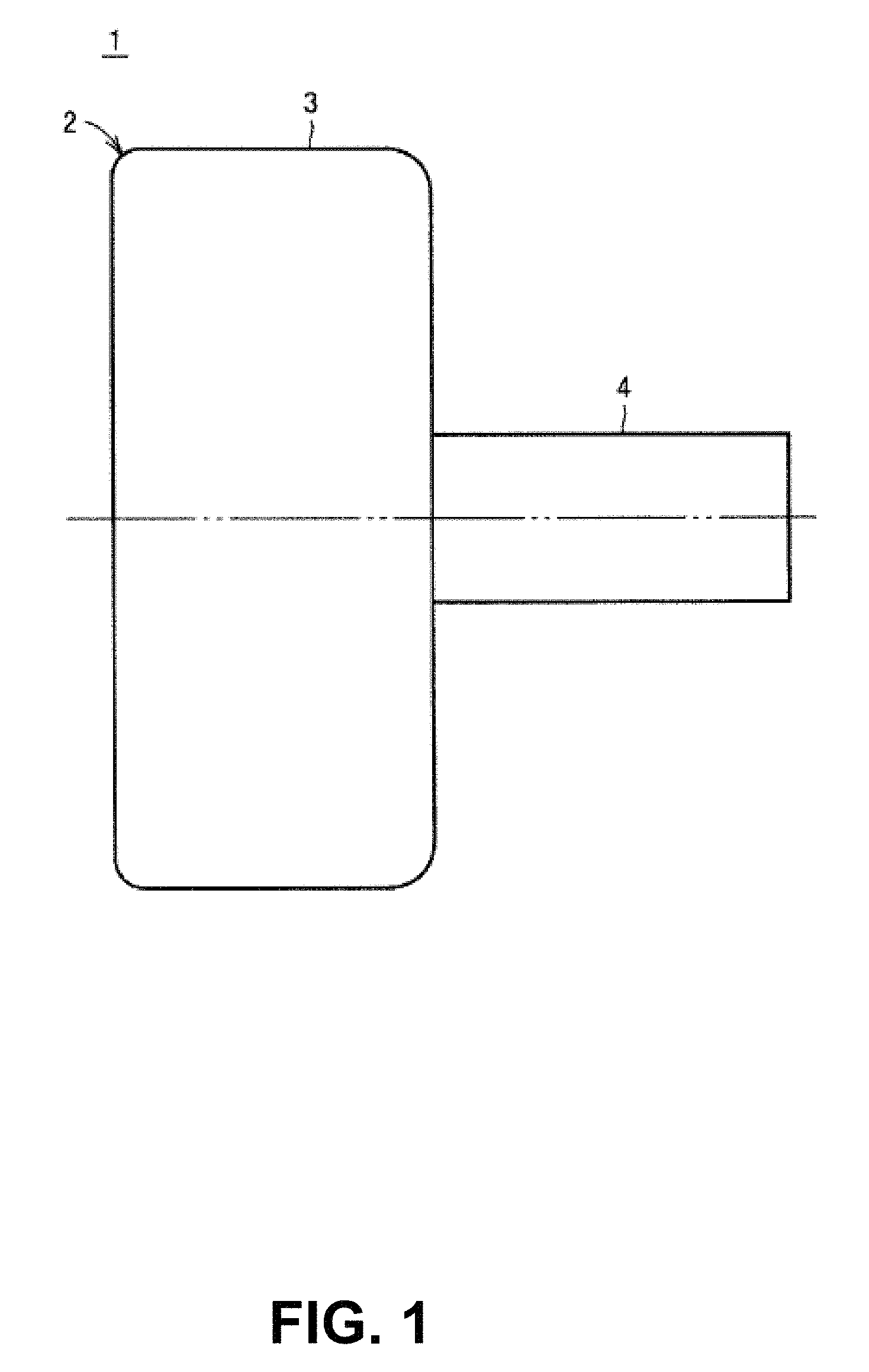
FIG. 1 shows an example centrifugal blood pump according to the disclosure.
FIG. 2 shows the blood pump of FIG. 1 in an alternate view.
FIG. 3 shows a cross-section of the blood pump of FIG. 1.
FIG. 4 shows another cross-section of the blood pump of FIG. 1.
FIG. 5 shows yet another cross-section of the blood pump of FIG. 1.
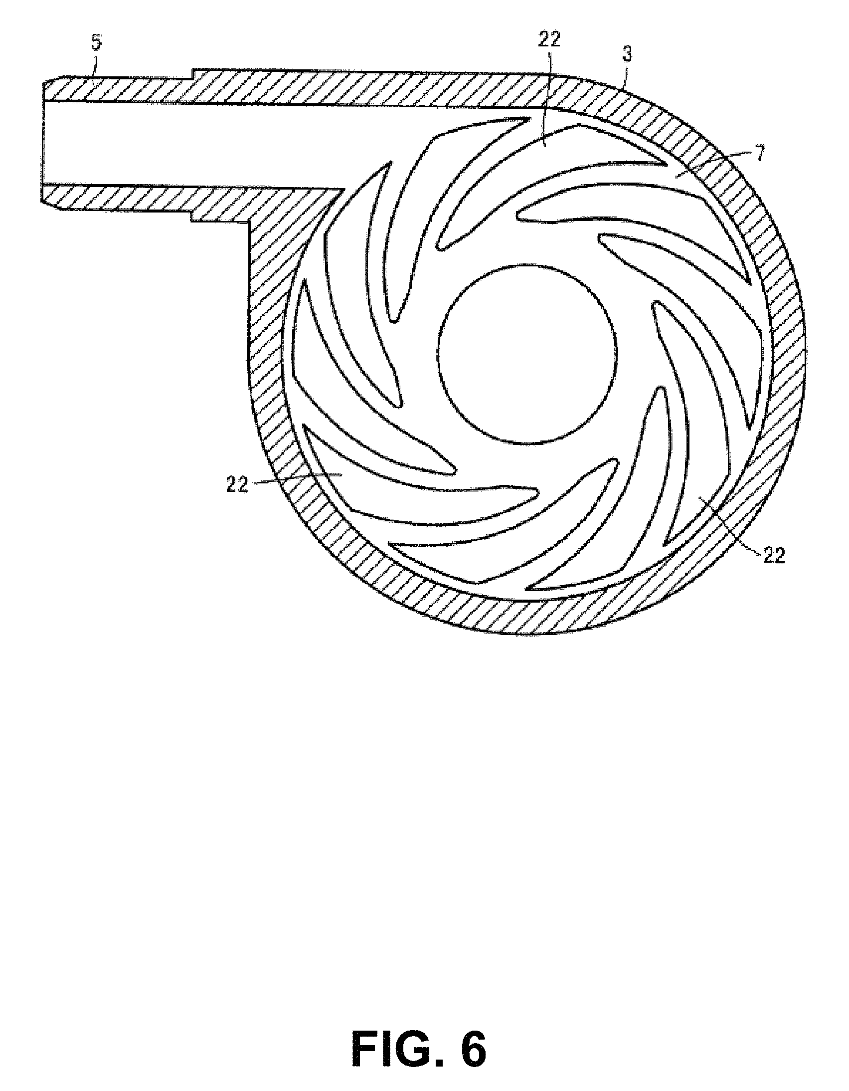
FIG. 6 shows yet another cross-section of the blood pump of FIG. 1.
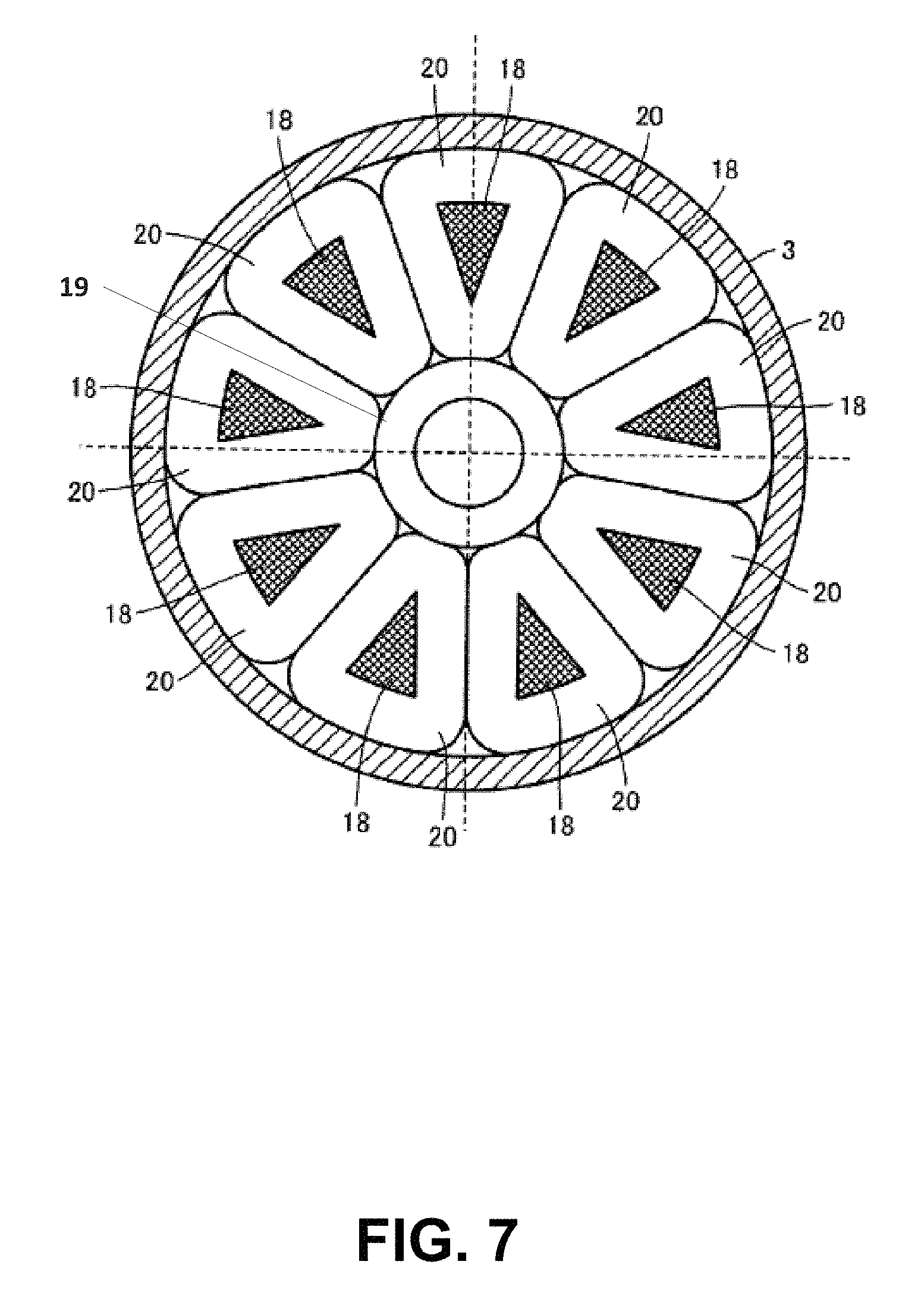
FIG. 7 shows yet another cross-section of the blood pump of FIG. 1.
FIG. 8 shows one embodiments of magnetic stabilization features of a blood pump according to embodiments.
FIG. 9 shows one embodiments of magnetic stabilization features of a blood pump according to embodiments.
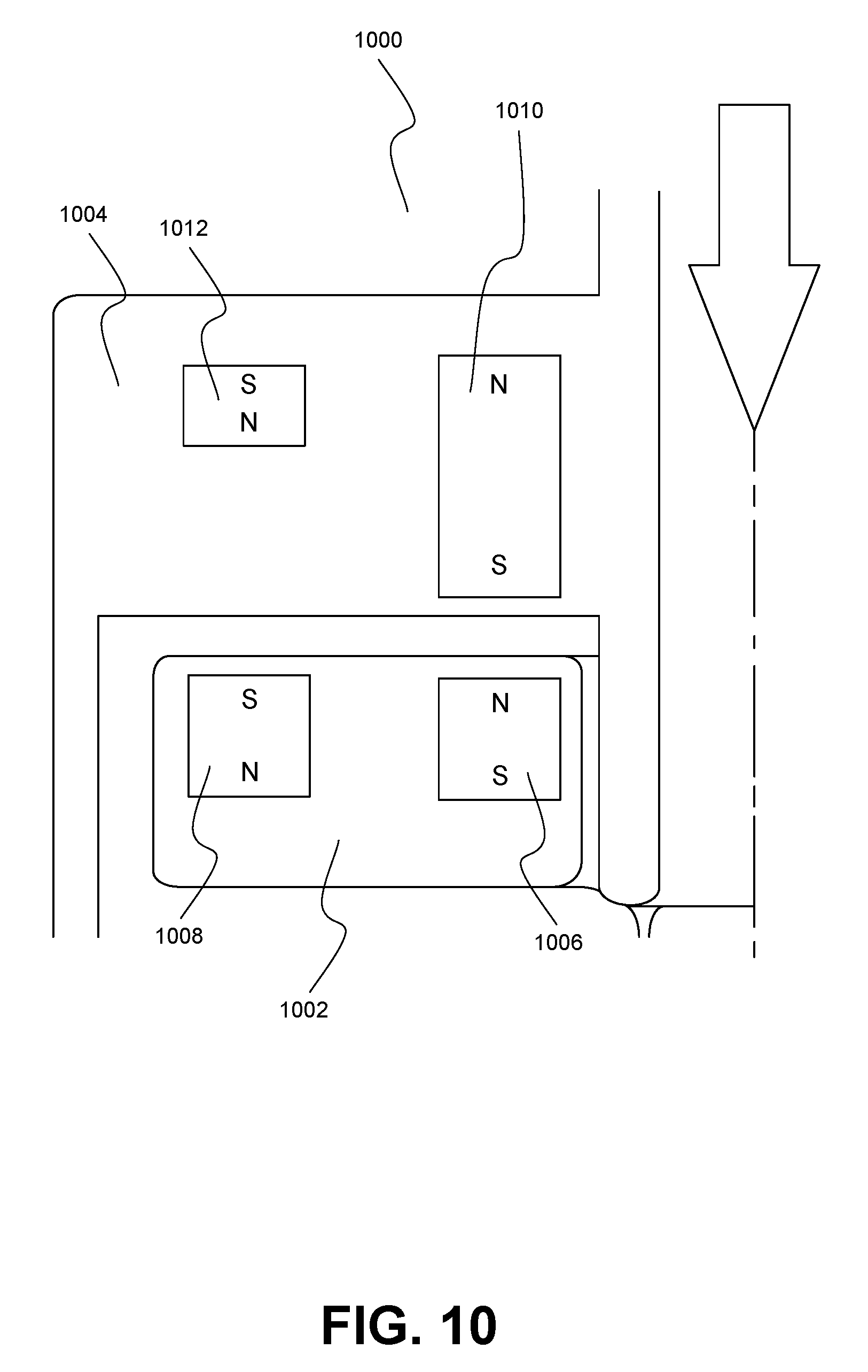
FIG. 10 shows one embodiments of magnetic stabilization features of a blood pump according to embodiments.
FIG. 11 shows one embodiments of magnetic stabilization features of a blood pump according to embodiments.
FIG. 12 shows one embodiments of magnetic stabilization features of a blood pump according to embodiments.
FIG. 13 shows one embodiments of magnetic stabilization features of a blood pump according to embodiments.
FIG. 14 shows one embodiments of magnetic stabilization features of a blood pump according to embodiments.
FIG. 15 shows one embodiments of magnetic stabilization features of a blood pump according to embodiments.
DETAILED DESCRIPTION OF THE INVENTION
The ensuing description provides exemplary embodiments only, and is not intended to limit the scope, applicability or configuration of the disclosure. Rather, the ensuing description of the exemplary embodiments will provide those skilled in the art with an enabling description for implementing one or more exemplary embodiments. It being understood that various changes may be made in the function and arrangement of elements without departing from the spirit and scope of the invention as set forth herein.
Specific details are given in the following description to provide a thorough understanding of the embodiments. However, it will be understood by one of ordinary skill in the art that the embodiments may be practiced without these specific details. For example, with regard to any specific embodiment discussed herein, any one or more details may or may not be present in all versions of that embodiment. Likewise, any detail from one embodiment may or may not be present in any particular version of another embodiment discussed herein. Additionally, well-known circuits, systems, processes, algorithms, structures, and techniques may be shown without unnecessary detail in order to avoid obscuring the embodiments. The absence of discussion of any particular element with regard to any embodiment herein shall be construed to be an implicit contemplation by the disclosure of the absence of that element in any particular version of that or any other embodiment discussed herein.
The present disclosure is directed to, among other things, minimizing or preventing a decrease in gap size at high impeller speeds between the outer edge of the impeller and the inner wall of a chamber of a blood pump. Some aspects of the disclosure are directed to reducing the risk of undesirable tilting of the impeller and/or improving the overall stability of the impeller during operation. Embodiments maintain an appropriately sized gap through all impeller speeds by decreasing the net attractive magnetic force on an outer portion of the impeller, or by having a lower net attractive force on an outer portion of the impeller than an inner portion. Although the feature or aspects of the present disclosure are not limited to a specific type of mechanical blood pump, an example of a blood pump in which embodiments of maintaining an appropriate gap size may be practiced is shown and described in connection with FIGS. 1-7. As will be understood by one of skill from the description herein, some of the features described increase a stabilizing force on the impeller over conventional non-contact pump bearings, in various respects, along the tilt axis.
In FIGS. 1-7, an exemplary centrifugal blood pump is shown that includes a pump unit 1 that includes a housing 2 made of a nonmagnetic material. Housing 2 includes a cylindrical body portion 3, a cylindrical blood inlet port 4 that extends from one end surface of body portion 3, and a cylindrical blood outlet port 5 that extends from another end surface of body portion 3. Blood outlet port 5 extends in a tangential direction of the outer circumferential surface of body portion 3.
As shown in FIG. 2, a position of one or more annular shaped magnetic members is shown. In some embodiments, pump unit 1 may include an inner annular magnetic member 30 and an outer annular magnetic member 32. Other embodiments may include one annular magnetic member or more than two annular magnetic members. The annular magnetic members 30 and 32 may each be formed from a single ring-shaped magnetic member, or may be formed from a number of magnetic members arranged in an annular pattern.
As shown in FIG. 3, a blood chamber 7 and a motor chamber 8 are partitioned from each other by a dividing wall 6 within housing 2. Blood chamber 7, as shown in FIGS. 3-4, includes a rotatable disc-shaped impeller 10 having a through hole 10a in a center thereof. Impeller 10 includes two shrouds 11, 12 in an annular shape, and a plurality (e.g., six) of vanes 13 formed between two shrouds 11 and 12. Shroud 11 is arranged on the blood inlet port 4 side, and shroud 12 is arranged on the dividing wall 6 side. Shrouds 11, 12 and vanes 13 are made of a nonmagnetic material.
A plurality (six in this case) of blood passages 14 are formed between two shrouds 11 and 12 and are partitioned from one another by the plurality of vanes 13. As shown in FIG. 4, blood passage 14 is in communication with through hole 10a at the center of impeller 10, and extends with through hole 10a of impeller 10 as a starting point to an outer circumference such that blood passage 14 gradually increases in width. In other words, each vane 13 is formed between two adjacent blood passages 14. In the first embodiment, the plurality of vanes 13 are provided at regular angular intervals, and each has the same shape. Thus, the plurality of blood passages 14 are provided at regular angular intervals and has the same shape.
When impeller 10 is driven to rotate, blood that has flowed in through blood inlet port 4 is delivered by centrifugal force from through hole 10a to an outer circumferential portion of impeller 10 via blood passages 14, and flows out through blood outlet port 5. It is contemplated that the blood inlet port 4 may be configured and/or arranged to minimize or prevent the formation of thrombosis within (i.e., internal) the blood inlet port 4, and also to minimize turbulence at a fluid interface between the blood inlet port 4 and the blood chamber 7.
A plurality of permanent magnets may be embedded in shroud 11. For example, an inner magnet 15 and an outer magnet 16 may be included in shroud 11. One or more annular magnetic members may be embedded in an inner wall of blood chamber 7 facing shroud 11. For example, inner annular magnetic member 30 and outer annular magnetic member may be embedded in the inner wall. The annular magnetic members 30 and 32 may be permanent magnets or may be electromagnetic elements. Either a soft magnetic element or a hard magnetic element may be used as the annular magnetic members 30 and/or 32.
The annular magnetic members 30 and 32 may each be formed as a single permanent magnet or as a plurality of permanent magnets. If a single permanent magnet is provided, the permanent magnet is formed in an annular or ring shape. If a plurality of permanent magnets are provided, the plurality of permanent magnets may be arranged at regular angular intervals along the same circle. While described as annular magnetic members, it will be appreciated that each of the magnetic members described herein may be formed from one or more magnets, and may be in any non-annular arrangement, such as other symmetrical shapes. In some embodiments, the inner annular magnetic member 30 may have a greater net attractive force with the inner magnet 15 than the net attractive force between the outer annular magnetic member 32 and the outer magnet 16. Such a configuration may decrease the tilt of the impeller, especially at high impeller speeds, thus maintaining a size of the gap between the outer edge of the impeller and the housing wall.
As shown in FIG. 4, a plurality (e.g., nine) of permanent magnets 17 are embedded in shroud 12. The plurality of permanent magnets 17 are arranged with a gap therebetween at regular angular intervals along the same circle such that magnetic polarities of adjacent permanent magnets 17 are different from each other. In other words, permanent magnet 17 having the N-pole toward motor chamber 8 and permanent magnet 17 having the S-pole toward motor chamber 8 are alternately arranged with a gap therebetween at regular angular intervals along the same circle.
As shown in FIG. 3 and FIG. 7, a plurality (e.g., nine) of magnetic elements 18 are provided in motor chamber 8. The plurality of magnetic elements 18 are arranged at regular angular intervals along the same circle to face the plurality of permanent magnets 17 in impeller 10. A base end of each of the plurality of magnetic elements 18 is joined to one disc-shaped magnetic element 19. A coil 20 is wound around each magnetic element 18. In the direction of a central axis of impeller 10, the length of magnetic element 18 is shorter than that of coil 20. That is, when an axial length of magnetic element 18 is expressed as x and an axial length of coil 20 is expressed as L relative to the surface of disc-shaped magnetic element 19, a relationship of 0<x<L is satisfied.
Referring back to FIG. 7, space for winding coil 20 is equally secured around the plurality of magnetic elements 18, and surfaces facing each other of every two adjacent magnetic elements 18 are provided substantially in parallel to each other. Thus, a large space for coils 20 can be secured and turns of coils 20 can be increased. As a result, large torque for driving impeller 10 to rotate can be generated. Further, copper loss that occurs in coils 20 can be reduced, thereby enhancing energy efficiency when impeller 10 is driven to rotate. The plurality of magnetic elements 18 may be formed in a cylindrical shape. In this case, a circumferential length of coils 20 can be minimized to reduce copper loss that occurs in coils 20, thereby enhancing energy efficiency when impeller 10 is driven to rotate.
An outline surface surrounding the plurality of magnetic elements 18 (a circle surrounding the peripheries of the plurality of magnetic elements 18 in FIG. 7) may correspond to an outline surface surrounding the plurality of permanent magnets 17 (a circle surrounding the peripheries of the plurality of magnetic elements 18 in FIG. 4), or the outline surface surrounding the plurality of magnetic elements 18 may be larger than the outline surface surrounding the plurality of permanent magnets 17. Further, it is preferable that magnetic element 18 be designed not to be magnetically saturated at maximum rating of pump 1 (a condition where torque for driving impeller 10 to rotate becomes maximum).
Voltages are applied to nine coils 20 in a power distribution system shifted by 120 degrees, for example. That is, nine coils 20 are divided into groups each including three coils. Voltages are applied to first to third coils 20 of each group, respectively. To first coil 20, a positive voltage is applied during a period of 0 to 120 degrees, 0 V is applied during a period of 120 to 180 degrees, a negative voltage is applied during a period of 180 to 300 degrees, and 0 V is applied during a period of 300 to 360 degrees. Accordingly, a tip surface of magnetic element 18 having first coil 20 wound therearound (end surface on the impeller 10 side) becomes the N-pole during the period of 0 to 120 degrees, and becomes the S-pole during the period of 180 to 300 degrees. A Voltage VV is delayed in phase from a voltage VU by 120 degrees, and a voltage VW is delayed in phase from voltage VV by 120 degrees. Thus, rotating magnetic field can be formed by applying voltages VU, VV, VW to first to third coils 20, respectively, so that impeller 10 can be rotated by attractive force and repulsion force between the plurality of magnetic elements 18 and the plurality of permanent magnets 17 in impeller 10.
When impeller 10 is rotating at a rated rotation speed, attractive force between the magnetic elements 15 and 16 and the annular magnetic members 30 and 32 and attractive force between the plurality of permanent magnets 17 and the plurality of magnetic elements 18 are set to be balanced with each other substantially around a center of a movable range of impeller 10 in blood chamber 7. Thus, force acting on impeller 10 due to the attractive force is very small throughout the movable range of impeller 10. Consequently, frictional resistance during relative slide between impeller 10 and housing 2 which occurs when impeller 10 is activated to rotate can be reduced. In addition, a surface of impeller 10 and a surface of an inner wall of housing 2 are not damaged (no projections and recesses in the surfaces) during the relative slide, and moreover, impeller 10 is readily levitated from housing 2 without contacting even when hydrodynamic force is small during low-speed rotation.
A number of grooves of hydrodynamic bearing 21 are formed in a surface of dividing wall X facing shroud 12 of impeller 10, and a number of grooves of hydrodynamic bearing 22 are formed in the inner wall of blood chamber 7 facing shroud 11. When a rotation speed of impeller 10 becomes higher than a prescribed rotation speed, a hydrodynamic bearing effect is produced between each of the grooves of hydrodynamic bearings 21 and 22 and impeller 10. As a result, drag is generated on impeller 10 from each of the grooves of hydrodynamic bearings 21 and 22, causing impeller 10 to rotate without contacting in blood chamber 7.
Specifically, as shown in FIG. 5, each of the grooves of hydrodynamic bearing 21 are formed with a size corresponding to shroud 12 of impeller 10. Each groove of hydrodynamic bearing 21 is positioned with one end on an edge (circumference) of a circular portion slightly distant from a center of dividing wall 6. Each groove extends from the edge spirally (in other words, in a curved manner) toward a portion near an outer edge of dividing wall 6 such that the groove of the hydrodynamic bearing 21 gradually increases in width. Each of the grooves of hydrodynamic bearing 21 has substantially the same shape, and the grooves are arranged at substantially regular intervals. Each groove of hydrodynamic bearing 21 includes a concave portion. Each groove may have a depth of between about 0.005 to 0.400 mm. Between about 6 to 36 grooves may form hydrodynamic bearing 21.
In FIG. 5, ten grooves in an equiangular arrangement with respect to the central axis of impeller 10 form hydrodynamic bearing 21. Since the grooves of hydrodynamic bearing 21 have a so-called inward spiral groove shape, clockwise rotation of impeller 10 causes an increase in fluid pressure from an outer diameter portion toward an inner diameter portion of the grooves for hydrodynamic bearing 21. As a result, a repulsive force that acts as a hydrodynamic force is generated between impeller 10 and dividing wall 6.
In some embodiments, alternatively, or in addition to, providing grooves for hydrodynamic bearing 21 in dividing wall 6, grooves for hydrodynamic bearing 21 may be provided in a surface of shroud 12 of impeller 10. The hydrodynamic bearing effect produced between impeller 10 and the grooves of hydrodynamic bearing 21, causes impeller 10 to move away from dividing wall 6 and to rotate without contacting the dividing wall 6. Accordingly, a blood flow path is secured between impeller 10 and dividing wall 6, thus preventing occurrence of blood accumulation therebetween and the resultant thrombus. Further, in a normal state, the grooves of hydrodynamic bearing 21 perform a stirring function between impeller 10 and dividing wall 6, thus preventing occurrence of partial blood accumulation therebetween.
It is preferable that a corner portion of each of grooves for hydrodynamic bearing 21 be rounded to have R of at least 0.05 mm. As a result, occurrence of hemolysis can further be reduced.
As with the grooves of hydrodynamic bearing 21, as shown in FIG. 6, the grooves of hydrodynamic bearing 22 are each formed with a size corresponding to shroud 11 of impeller 10. Each groove of hydrodynamic bearing 22 has one end on an edge (circumference) of a circular portion slightly distant from a center of the inner wall of blood chamber 7. The groove extends spirally (in other words, in a curved manner) toward a portion near an outer edge of the inner wall of blood chamber 7 such that the groove gradually increases in width. Each of the grooves has substantially the same shape. The grooves are arranged at substantially regular intervals. Each groove of hydrodynamic bearing 22 includes a concave portion. Each groove may have a depth of between about 0.005 to 0.4 mm. It is preferable that about 6 to 36 grooves form hydrodynamic bearing 22. In FIG. 6, ten grooves forming hydrodynamic bearing 22 are equiangularly arranged with respect to the central axis of impeller 10.
Alternatively, or in addition to, providing the grooves of hydrodynamic bearing 22 in the inner wall of blood chamber 7, the grooves of hydrodynamic bearing 22 may be provided in a surface of shroud 11 of impeller 10. It is preferable that a corner portion of each of grooves of hydrodynamic bearing 22 be rounded to have R of at least 0.05 mm. As a result, occurrence of hemolysis can further be reduced
The hydrodynamic bearing effect produced between impeller 10 and the grooves for hydrodynamic bearing 22 causes impeller 10 to move away from the inner wall of blood chamber 7 and rotates without contacting the inner wall. In addition, when pump unit 1 is subjected to external impact or when the hydrodynamic force generated by hydrodynamic bearing 21 becomes excessive, impeller 10 can be prevented from being in close contact with the inner wall of blood chamber 7. The hydrodynamic force generated by hydrodynamic bearing 21 may be different from the hydrodynamic force generated by hydrodynamic bearing 22.
It is preferable that impeller 10 rotate in a state where a gap between shroud 12 of impeller 10 and dividing wall 6 is substantially equal to a gap between shroud 11 of impeller 10 and the inner wall of blood chamber 7. If one of the gaps becomes narrower due to serious disturbance such as fluid force acting on impeller 10, it is preferable that grooves of hydrodynamic bearing 21 and 22 have different shapes so that the hydrodynamic force generated by the hydrodynamic bearing on the narrower side becomes higher than the hydrodynamic force generated by the other hydrodynamic bearing to make the gaps substantially equal to each other.
While each groove of hydrodynamic bearings 21 and 22 has the inward spiral groove shape shown in FIGS. 5-6, grooves having another shape may be used. Nevertheless, for blood circulation, it is preferable to employ grooves having the inward spiral groove shape, which allows for a smooth flow of blood.
As mentioned above, it is contemplated that the blood inlet port 4 may be configured and/or arranged to minimize or prevent the formation of thrombosis within (i.e., internal) the blood inlet port 4, and also to minimize turbulence at a fluid interface between the blood inlet port 4 and the blood chamber 7. In general, it is contemplated that thrombosis formation may occur due to a vortex forming in or within one or both of blood inlet port 4 and the blood chamber 7 in a location near or adjacent blood inlet port 4, and/or due to stress or forces imparted on blood as it transitions into a spinning motion once it reaches the impeller 10.
FIGS. 8-15 depict embodiments of pumps using one or more annular magnetic members of a magnetic suspension system to maintain a size of a gap between an impeller and a chamber wall of a housing at high impeller speeds. Theses pumps may be configured as those described in FIGS. 1-7 above. The annular magnetic members may correspond to the annular magnetic members 30 and 32 described herein. The magnetic suspension systems are often made up of magnetic elements within the impeller, annular magnetic members embedded within a housing of the pump, a stator motor, and/or hydrostatic bearings formed in the housing. Embodiments maintain this gap size by producing a lower net attractive force at an outer or distal portion of the impeller than at an inner or proximal portion of the impeller. In some embodiments this net attractive force relationship is achieved by decreasing the attractive force at the outer portion or by producing a repulsive force at the outer portion. Other embodiments achieve the greater inner attractive force by increasing the attractive force at the inner portion of the impeller. In other embodiments, the gap may be maintained by using electromagnets as the annular magnetic members and utilizing active magnetic control to adjust the magnetic forces as impeller speeds and/or gap size change. Alternative methods of increasing and/or maintaining the gap size at high impeller speeds may also include increasing the gap between the motor stator and the motor magnet, although his may decrease the efficiency of the motor. It will be appreciated that combinations of the techniques described herein may be used to further adjust and/or maintain the gap size.
FIGS. 8 and 9 depict systems that decrease the outer annular magnetic member's magnetic force to create a greater net magnetic attraction at the inner annular magnetic member. In FIG. 8, a pump 800 having a housing 802 is shown. An impeller 804 is shown having a plurality of magnetic elements embedded therein. The impeller is configured to rotate within the housing 802. Here, an inner magnetic element 806 and an outer magnetic element 808 are embedded within impeller 804. One or more annular magnetic members may be embedded within housing 802. For example, an inner annular magnetic member 810 and an outer annular magnetic member 812 are embedded within a side wall of the housing 802. As shown here, by making a distance between the inner annular magnetic member 810 and inner magnetic element 806 less than a distance between outer annular magnetic member 812 and outer magnetic element 808, the net attractive force along the outer edge of impeller 802 may be decreased and/or made lower than the net attractive force at an inner portion of the impeller 802. This lessened attractive force results in a reduction of negative stiffness at the outer annular magnetic member 812 and an increase in the gap between the impeller 802 and the inner wall of the housing 804. Making the distance between the inner magnets smaller than the distance between the outer magnets can be achieved by moving the inner annular magnetic member 810 closer to the impeller, by moving the outer annular magnetic member 812 away from the impeller, and/or by a combination of both.
In some embodiments, making the distance between the inner magnets smaller than the distance between the outer magnets can be achieved by changing a position of the inner magnet and/or the outer magnet relative to the impeller as shown in FIG. 9. For example, a pump 900 may have a housing 904 and an impeller 906 such as described in FIG. 8. An inner magnet 906 of the impeller 902 may be moved closer to an inner annular magnetic member 910 within the housing 904 and/or an outer magnet 908 may be moved away from an outer annular magnetic member 912. In some embodiments, one or more of both the housing magnetic members 810 and 812 and the impeller magnetic elements 806 and 808 may be positioned to create the larger distance between the outer magnets than the inner magnets. In some embodiments, the net force difference between the inner and outer portions of the impeller may be attained by decreasing the attractive force at the outer annular magnetic member, such as by reducing the magnet size and/or otherwise reducing the strength of the outer annular magnetic member 912.
FIGS. 10 and 11 depict embodiments of pumps that increase a magnetic force of an inner annular magnetic member and decrease or eliminate a magnetic force of an outer annular magnetic member. For example, in FIG. 10, a pump 1000 is shown having an impeller 1002, housing 1004, an inner magnetic element 1006, and an outer magnetic element 1008 as described above with regard to FIG. 8. Pump 1000 may include an inner annular magnetic member 1010 having a net magnetic attraction with the inner magnetic element 1006 that is greater than a net magnetic attraction between an outer annular magnetic member 1012 and the outer magnetic element 1008. In pump 1000, this is done by increasing the magnetic force of the inner annular magnetic member 1010 in combination with reducing the magnetic force of the outer annular magnetic member 1012 and/or by increasing the distance between the outer annular magnetic member 1012 and the outer magnetic element 1008. The increase in magnetic force of the inner annular magnetic member may be realized by increasing the magnet volume and/or by using a stronger magnet. In some embodiments, the magnetic force of the inner annular magnetic member 1010 may be increased sufficiently such that the outer annular magnetic member 1012 and/or outer magnetic element 1008 may be eliminated. For example, FIG. 11 shows a pump 1100 having only a strong inner annular magnetic member 1110 and an inner magnetic element 1106.
In some embodiments, the gap between the impeller and the housing may be maintained by increasing the attractive force of the inner annular magnetic member while using an opposite polarity magnet as the outer annular magnetic member to create a repulsive force on the outer edge of the impeller and to increase the impeller suspension stiffness. For example, FIG. 12 shows a pump 1200 having an inner annular magnetic member 1210 having a sufficiently high attractive magnetic force and an outer annular magnetic member 1212 that has a polarity relative to an outer magnetic element 1208 to create a repulsive force that serves to maintain the gap size, even at high impeller speeds.
FIG. 13 shows one embodiment of a pump 1300 where a diameter of an outer annular magnetic member 1312 is increased to be larger than a diameter of an outer magnetic element 1308 on an impeller 1302 and/or to extend radially beyond at least a portion of the outer magnetic element 1308. The outer annular magnetic member 1312 also has a polarity selected to create a net repulsive force with the outer magnetic element 1308. When the outer annular magnetic member 1312 extends beyond at least a portion of the outer magnetic element 1308, the repulsive force has a force component toward the rotational axis of the impeller 1302, which increases the radial stiffness. The impeller rotation center shifts toward an outlet side of pump 1300 when the flow rate is high. The repulsive force of the rotational axis direction increases as the impeller is pushed toward the outlet side, compensating against pump pressure distribution due to the high flow rate. Thus, the repulsive force produce by the outer annular magnetic member 1312 helps maintain the impeller position, and thus gap size, as impeller speeds increase.
In some embodiments, reduction of a diameter of an inner annular magnetic member may be used in conjunction with increasing a diameter of an outer annular magnetic member, resulting in an increase in the radial stiffness of the magnetic suspension system of the pump. For example, FIG. 14 shows a pump 1400 having an outer annular magnetic member 1412 of increased diameter and an inner magnetic member 1410 having a reduced diameter. By reducing the diameter of the inner annular magnetic member 1410 such that the inner annular magnetic member 1410 is positioned at least partially inward of the inner magnetic element 1406, a thickness of a pump housing 1404 may be reduced by putting an inner annular magnetic member 1410 of increased size within dead space of a pump inflow conduit 1414. This positioning results in an increase in the negative stiffness of the magnetic suspension system. The radial component of the repulsive force of the outer annular magnetic member maintains the impeller radial stiffness as the position of the inner annular magnetic member 1410 increases the negative stiffness. Additionally, the inward position of the inner annular magnetic member 1410 increases the magnetic resistance while reducing the magnetic flux, and thus, the net attractive force acting on the impeller 1402. The repulsive force of the outer annular magnetic member 1412 helps compensate for the reduction of attractive force of the inner annular magnetic member 1410 to maintain the gap size between the housing 1404 and the impeller 1402.
In some embodiments, a ferromagnetic ring, such as a steel ring, may be positioned between an inner annular magnetic member and an inner magnetic element when the inner annular magnetic member has a diameter positioned inward of an inner magnetic element on an impeller. FIG. 15 shows a pump 1500 having an outer annular magnetic member 1512 extending radially beyond an outer magnetic element 1508 and an inner annular magnetic member 1510 positioned inward of an inner magnetic element 1506. Pump 1500 also includes a ferromagnetic ring 1516 positioned between inner annular magnetic member 1510 and inner magnetic element 1506. The ring 1516 skews the magnetic flux such that the attractive force from the inner annular magnetic member 1510 is better directed to act upon the inner magnetic element 1506.
The invention has now been described in detail for the purposes of clarity and understanding. However, it will be appreciated that certain changes and modifications may be practiced within the scope of the disclosure.
* * * * *
References
D00000
D00001
D00002
D00003
D00004
D00005
D00006
D00007
D00008
D00009
D00010
D00011
D00012

D00013

D00014

D00015

XML
uspto.report is an independent third-party trademark research tool that is not affiliated, endorsed, or sponsored by the United States Patent and Trademark Office (USPTO) or any other governmental organization. The information provided by uspto.report is based on publicly available data at the time of writing and is intended for informational purposes only.
While we strive to provide accurate and up-to-date information, we do not guarantee the accuracy, completeness, reliability, or suitability of the information displayed on this site. The use of this site is at your own risk. Any reliance you place on such information is therefore strictly at your own risk.
All official trademark data, including owner information, should be verified by visiting the official USPTO website at www.uspto.gov. This site is not intended to replace professional legal advice and should not be used as a substitute for consulting with a legal professional who is knowledgeable about trademark law.