Cable pathway divider and method for installing same
Krietzman
U.S. patent number 10,243,334 [Application Number 15/994,380] was granted by the patent office on 2019-03-26 for cable pathway divider and method for installing same. This patent grant is currently assigned to Chatsworth Products, Inc.. The grantee listed for this patent is CHATSWORTH PRODUCTS, INC.. Invention is credited to William Drew Krietzman.


View All Diagrams
| United States Patent | 10,243,334 |
| Krietzman | March 26, 2019 |
Cable pathway divider and method for installing same
Abstract
A cable pathway divider, for installation on a cable runway, includes a pair of post halves and a ring-shaped locking member. Each post half includes a base portion and an extension portion, and the base portions of the post halves are arrangeable at opposite sides of a cross member of a cable runway. The post halves are securable to one another from opposite sides of the cross member, via clamping arrangement of the ring-shaped locking member relative to the post halves, such that the extension portions extend into a space above the cable runway to divide the cable runway into at least two cable paths.
| Inventors: | Krietzman; William Drew (Castle Rock, CO) | ||||||||||
|---|---|---|---|---|---|---|---|---|---|---|---|
| Applicant: |
|
||||||||||
| Assignee: | Chatsworth Products, Inc.
(Agoura Hills, CA) |
||||||||||
| Family ID: | 62554801 | ||||||||||
| Appl. No.: | 15/994,380 | ||||||||||
| Filed: | May 31, 2018 |
Related U.S. Patent Documents
| Application Number | Filing Date | Patent Number | Issue Date | ||
|---|---|---|---|---|---|
| 15352538 | Nov 15, 2016 | 10003180 | |||
| 62260888 | Nov 30, 2015 | ||||
| 62260936 | Nov 30, 2015 | ||||
| 62260895 | Nov 30, 2015 | ||||
| Current U.S. Class: | 1/1 |
| Current CPC Class: | H02G 3/04 (20130101); H02G 3/0456 (20130101); F16L 3/22 (20130101); F16L 3/26 (20130101) |
| Current International Class: | A47F 5/00 (20060101); F16L 3/22 (20060101); H02G 3/04 (20060101); F16L 3/26 (20060101) |
References Cited [Referenced By]
U.S. Patent Documents
| 824544 | June 1906 | Hossege |
| D171224 | December 1953 | Pfaff, Jr. |
| 3042351 | July 1962 | DuBois |
| 3485937 | December 1969 | Caveney |
| 3705949 | December 1972 | Weiss |
| 3761603 | September 1973 | Hays et al. |
| 3890459 | June 1975 | Caveney |
| 3968322 | July 1976 | Taylor |
| 4046957 | September 1977 | Taylor et al. |
| 4136257 | January 1979 | Taylor |
| 4398564 | August 1983 | Young et al. |
| 4470622 | September 1984 | Pate |
| 5009383 | April 1991 | Chapman |
| 5023404 | June 1991 | Hudson et al. |
| 5235136 | August 1993 | Santucci et al. |
| 5384937 | January 1995 | Simon |
| 5531410 | July 1996 | Simon |
| 5580014 | December 1996 | Rinderer |
| 5586012 | December 1996 | Lerman |
| 5602364 | February 1997 | Ustin |
| 5640482 | June 1997 | Barry et al. |
| 5758002 | May 1998 | Walters |
| 5806811 | September 1998 | Viklund et al. |
| 5902961 | May 1999 | Viklund et al. |
| 5921402 | July 1999 | Magenheimer |
| 5927658 | July 1999 | Gerster |
| 5953870 | September 1999 | Jette |
| 6023024 | February 2000 | Stjerneby |
| 6044194 | March 2000 | Meyerhoefer |
| 6061884 | May 2000 | Ohms et al. |
| 6105218 | August 2000 | Reekie |
| 6129316 | October 2000 | Bauer |
| 6138961 | October 2000 | Zweig |
| 6181862 | January 2001 | Noble et al. |
| 6193434 | February 2001 | Durin et al. |
| 6215069 | April 2001 | Martin et al. |
| 6220554 | April 2001 | Daoud |
| 6227502 | May 2001 | Derman |
| 6239364 | May 2001 | Nickel |
| 6245998 | June 2001 | Curry et al. |
| 6247871 | June 2001 | Nickel et al. |
| 6311732 | November 2001 | Nickel |
| 6340141 | January 2002 | Rinderer |
| 6347493 | February 2002 | Jette |
| 6398149 | June 2002 | Hines et al. |
| 6402418 | June 2002 | Durin et al. |
| 6427400 | August 2002 | Greenblatt |
| 6437243 | August 2002 | VanderVelde et al. |
| 6437244 | August 2002 | VanderVelde |
| 6449912 | September 2002 | Jette |
| 6463704 | October 2002 | Jette |
| 6467633 | October 2002 | Mendoza |
| 6468112 | October 2002 | Follingstad et al. |
| 6489565 | December 2002 | Krietzman et al. |
| 6489566 | December 2002 | Durin |
| 6584267 | June 2003 | Caveney et al. |
| 6590154 | July 2003 | Badey et al. |
| 6600107 | July 2003 | Wright et al. |
| 6605782 | August 2003 | Krietzman et al. |
| 6614978 | September 2003 | Caveney et al. |
| 6637165 | October 2003 | Jette |
| 6637704 | October 2003 | Jette |
| 6672022 | January 2004 | Simmons |
| 6677530 | January 2004 | Blaha |
| 6729606 | May 2004 | Durin |
| 6760531 | July 2004 | Solheid et al. |
| 6766093 | July 2004 | McGrath et al. |
| 6796437 | September 2004 | Krampotich et al. |
| 6855884 | February 2005 | Spagnoli et al. |
| 6884942 | April 2005 | McGrath et al. |
| 6918796 | July 2005 | Elliot et al. |
| 6964588 | November 2005 | Follingstad et al. |
| 6981893 | January 2006 | Barker et al. |
| 7083051 | August 2006 | Smith et al. |
| 7130521 | October 2006 | McCrary |
| 7168212 | January 2007 | Jette |
| 7220150 | May 2007 | Follingstad et al. |
| 7285027 | October 2007 | McGrath et al. |
| 7362941 | April 2008 | Rinderer et al. |
| 7373759 | May 2008 | Simmons |
| 7381100 | June 2008 | Follingstad et al. |
| 7425678 | September 2008 | Adducci et al. |
| 7427713 | September 2008 | Adducci et al. |
| 7437048 | October 2008 | Farrell et al. |
| 7458859 | December 2008 | McGrath et al. |
| 7476801 | January 2009 | Davis et al. |
| 7476804 | January 2009 | Adducci et al. |
| 7485803 | February 2009 | Adducci et al. |
| 7495169 | February 2009 | Adducci et al. |
| 7498512 | March 2009 | Adducci et al. |
| 7504581 | March 2009 | Adducci et al. |
| 7527226 | May 2009 | Kusuda et al. |
| 7546987 | June 2009 | Sinkoff |
| 7592541 | September 2009 | Adducci et al. |
| 7608779 | October 2009 | Adducci et al. |
| 7637771 | December 2009 | Laursen |
| 7667135 | February 2010 | Adducci et al. |
| 7718891 | May 2010 | Adducci et al. |
| 7762405 | July 2010 | Vogel et al. |
| 7772489 | August 2010 | Adducci et al. |
| 7778513 | August 2010 | Rinderer et al. |
| 7781675 | August 2010 | Adducci et al. |
| 7795532 | September 2010 | Walker |
| 7893356 | February 2011 | Garza et al. |
| 7938371 | May 2011 | Oga |
| 7939763 | May 2011 | Jones et al. |
| 7952027 | May 2011 | Grelck |
| 7954776 | June 2011 | Davis et al. |
| 7973242 | July 2011 | Jones |
| 7974105 | July 2011 | Dean, Jr. et al. |
| 7999183 | August 2011 | Garza et al. |
| 8003890 | August 2011 | Donowho et al. |
| 8014171 | September 2011 | Kelly |
| 8035965 | October 2011 | Adducci et al. |
| 8056868 | November 2011 | Vander Griend |
| 8097808 | January 2012 | Quertelet et al. |
| 8138419 | March 2012 | Garza et al. |
| 8237052 | August 2012 | Adducci et al. |
| 8263867 | September 2012 | Garza et al. |
| 8273989 | September 2012 | Garza et al. |
| 8330043 | December 2012 | Alaniz et al. |
| 8395046 | March 2013 | Nicewicz et al. |
| 8411465 | April 2013 | Dean, Jr. et al. |
| 8437147 | May 2013 | Dean, Jr. et al. |
| 8558113 | October 2013 | Krietzman et al. |
| 8757560 | June 2014 | Darnell |
| 8879881 | November 2014 | Cote |
| 9112341 | August 2015 | Eshima |
| 9350146 | May 2016 | Krietzman et al. |
| 9363922 | June 2016 | Larsen |
| 9402329 | July 2016 | Chen et al. |
| 9548597 | January 2017 | Vacca |
| 9556976 | January 2017 | Thompson |
| 10003180 | June 2018 | Krietzman |
| 2001/0022231 | September 2001 | Dyer |
| 2002/0074149 | June 2002 | Lawrence |
| 2002/0184843 | December 2002 | Jette |
| 2004/0055232 | March 2004 | Jette |
| 2004/0056157 | March 2004 | Dufourg |
| 2004/0094491 | May 2004 | Smith et al. |
| 2005/0247650 | November 2005 | Vogel et al. |
| 2006/0038091 | February 2006 | Winn |
| 2006/0162948 | July 2006 | Rinderer et al. |
| 2006/0171651 | August 2006 | Laursen |
| 2007/0210679 | September 2007 | Adducci et al. |
| 2007/0210680 | September 2007 | Appino et al. |
| 2007/0210681 | September 2007 | Adducci et al. |
| 2007/0210683 | September 2007 | Adducci et al. |
| 2007/0210686 | September 2007 | Adducci et al. |
| 2007/0221393 | September 2007 | Adducci et al. |
| 2007/0249237 | October 2007 | Follingstad et al. |
| 2007/0293138 | December 2007 | Adducci et al. |
| 2008/0067904 | March 2008 | Adducci et al. |
| 2008/0074849 | March 2008 | Adducci et al. |
| 2008/0174217 | July 2008 | Walker |
| 2008/0271918 | November 2008 | Caveney et al. |
| 2009/0224110 | September 2009 | Donowho et al. |
| 2009/0236117 | September 2009 | Garza et al. |
| 2009/0273915 | November 2009 | Dean, Jr. et al. |
| 2010/0101820 | April 2010 | Alaniz et al. |
| 2010/0122830 | May 2010 | Garza et al. |
| 2010/0126750 | May 2010 | Garza et al. |
| 2010/0126751 | May 2010 | Garza et al. |
| 2010/0171004 | July 2010 | Young |
| 2010/0193754 | August 2010 | Garza et al. |
| 2010/0200707 | August 2010 | Garza et al. |
| 2011/0011612 | January 2011 | Sayres |
| 2011/0056895 | March 2011 | Tichy |
| 2011/0211328 | September 2011 | Dean, Jr. et al. |
| 2011/0211329 | September 2011 | Dean, Jr. et al. |
| 2012/0062091 | March 2012 | Donowho et al. |
| 2012/0181906 | July 2012 | Caveney |
| 2012/0267991 | October 2012 | Adducci et al. |
| 2018/0110153 | April 2018 | Hennrich et al. |
| 1337647 | Nov 1995 | CA | |||
| 2137879 | Mar 1999 | CA | |||
| 0298825 | Apr 1992 | EP | |||
| 2007578 | Jan 1992 | ES | |||
| 2617341 | Dec 1988 | FR | |||
| 2285343 | Jul 1995 | GB | |||
| 87843 | May 1989 | PT | |||
| 9715774 | May 1997 | WO | |||
| 2009089307 | Jul 2009 | WO | |||
| 2009089307 | Dec 2009 | WO | |||
| 2018022721 | Feb 2018 | WO | |||
Other References
|
Information Disclosure Statement (IDS) letter regarding common patent application(s), dated Jul. 20, 2018. cited by applicant. |
Primary Examiner: Millner; Monica E
Attorney, Agent or Firm: Tillman Wright, PLLC Wright; James D. Higgins; David R.
Parent Case Text
CROSS-REFERENCE TO RELATED APPLICATIONS
The present application is a U.S. continuation patent application of, and claims priority under 35 U.S.C. .sctn. 120 to, U.S. nonprovisional patent application Ser. No. 15/352,538, filed Nov. 15, 2016, which '538 application issued as U.S. Pat. No. 10,003,180 on Jun. 19, 2018, which '538 application and the patent issuing therefrom are each incorporated by reference herein in their entirety, and which '538 application is a U.S. nonprovisional patent application of, and claims priority under 35 U.S.C. .sctn. 119(e) to each of: (a) U.S. provisional patent application Ser. No. 62/260,888, filed Nov. 30, 2015 and entitled, "CABLE PATHWAY DIVIDER," which '888 application is incorporated by reference herein in its entirety; (b) U.S. provisional patent application Ser. No. 62/260,895, filed Nov. 30, 2015 and entitled, "INSIDE CABLE DROP FOR CABLE RUNWAY," which '895 application is incorporated by reference herein in its entirety, and a copy of which '895 application is appended hereto as Appendix A, which appendix is likewise incorporated by reference herein in its entirety; and (c) U.S. provisional patent application Ser. No. 62/260,936, filed Nov. 30, 2015 and entitled, "OUTSIDE CABLE DROP FOR CABLE RUNWAY," which '936 application is incorporated by reference herein in its entirety, and a copy of which '936 application is appended hereto as Appendix B, which appendix is likewise incorporated by reference herein in its entirety.
Claims
What is claimed is:
1. A cable pathway divider for installation on a cable runway, the cable pathway divider comprising: a pair of post halves, each having a base portion and an extension portion; and a separate ring-shaped locking member that defines an opening; wherein the post halves are arrangeable at opposite sides of a cross member of a cable runway, with the cross member positioned between the base portions and with the extension portions extending in a direction above the cable runway; wherein the extension portions are positionable through the opening of the ring-shaped locking member to facilitate clamping arrangement of the ring-shaped locking member relative to the post halves, thereby securing the cross member between the post halves and dividing a space above the cable runway into at least two cable paths; wherein at least one of the pair of post halves includes a retaining boss; and wherein, when the pair of post halves are coupled together, the retaining boss protrudes outwardly, away from the pair of post halves, and is arranged to retain the ring-shaped locking member in a locked state relative to the pair of post halves.
2. The cable pathway divider of claim 1, wherein the post halves are interlocking post halves.
3. The cable pathway divider of claim 1, wherein the post halves are identical to one another.
4. The cable pathway divider of claim 1, wherein the extension portion of each post half has a generally tapered shape such that the extension portion is wider at a proximal end than at a distal end.
5. The cable pathway divider of claim 1, wherein each post half includes one or more alignment tabs to facilitate alignment when the post halves are coupled together during installation.
6. The cable pathway divider of claim 1, wherein each post half includes a prong and a socket disposed at opposite sides of a center line.
7. The cable pathway divider of claim 6, wherein, when the post halves are coupled together during installation, the prong of each post half is received within the socket of the other post half.
8. The cable pathway divider of claim 1, wherein the base portion of each post half includes a receiving channel.
9. The cable pathway divider of claim 8, wherein, when the post halves are coupled together during installation, the receiving channels receive the cross member of the cable runway.
10. The cable pathway divider of claim 1, wherein each post half includes a slot at a distal end of the extension portion and a hinge member having a tab, each of the slot and the hinge member being disposed at opposite sides of a center line.
11. The cable pathway divider of claim 10, wherein, when the post halves are coupled during installation, the tab of each post half is received within the slot of the other post half, thereby defining a hinge mechanism.
12. The cable pathway divider of claim 1, wherein the ring-shaped locking member includes tapered grip sections, arranged at opposite exterior-facing sides thereof, to facilitate arrangement of the ring-shaped locking member relative to the post halves.
13. The cable pathway divider of claim 1, wherein the ring-shaped locking member includes at least one recess to accommodate the retaining boss.
14. A multi-path cable runway comprising: a pair of spaced-apart parallel rails and at least one cross member interconnected between the pair of spaced-apart parallel rails, the pair of spaced-apart parallel rails and the at least one cross member, together, defining a cable runway; and at least one cable pathway divider installed on the at least one cross member, the at least one cable pathway divider including a pair of post halves, each having a base portion and an extension portion, and further including a ring-shaped locking member that secures the pair of post halves together via clamping arrangement; wherein, with the at least one cable divider installed on the at least one cross member, the base portions of the post halves are arranged at opposite sides of the at least one cross member and the extension portions of the post halves extend into a space above the cable runway to divide the cable runway into at least two cable paths; wherein at least one of the pair of post halves of the at least one cable pathway divider includes a retaining boss; and wherein, when the pair of post halves are coupled together, the retaining boss protrudes outwardly, away from the pair of post halves, and is arranged to retain the ring-shaped locking member in a locked state relative to the pair of post halves.
15. The multi-path cable runway of claim 14, wherein the post halves of the at least one cable pathway divider are interlocking post halves.
16. The multi-path cable runway of claim 14, wherein the post halves of the at least one cable pathway divider are identical to one another.
17. The multi-path cable runway of claim 14, wherein the extension portion of each post half of the at least one cable pathway divider has a generally tapered shape such that the extension portion is wider at a proximal end than at a distal end.
18. The multi-path cable runway of claim 14, wherein each post half of the at least one cable pathway divider includes one or more alignment tabs to facilitate alignment of the post halves relative to one another.
19. The multi-path cable runway of claim 14, wherein each post half of the at least one cable pathway divider includes a prong and a socket disposed at opposite sides of a center line.
20. The multi-path cable runway of claim 14, wherein the ring-shaped locking member includes at least one recess to accommodate the retaining boss.
Description
COPYRIGHT STATEMENT
All of the material in this patent document is subject to copyright protection under the copyright laws of the United States and other countries. The copyright owner has no objection to the facsimile reproduction by anyone of the patent document or the patent disclosure, as it appears in official governmental records but, otherwise, all other copyright rights whatsoever are reserved.
BACKGROUND OF THE PRESENT INVENTION
Field of the Present Invention
The present invention relates generally to dividers for cable pathways, and, in particular, to cable pathway dividers that can be installed or removed without the aid of tools.
Background
Cable runways are commonly used in data centers or equipment rooms to define a path for routing cables. Each cable runway generally includes a pair of spaced-apart parallel rails and a plurality of transverse cross members interconnecting the rails at various intervals, thereby having the general appearance of a ladder. Many cable runways are modular in nature, and a plurality of cable runways may be installed in conjunction with one another to produce a cable runway system. Once the cable runway system is installed, individual cables and cable bundles are supported along the cable runways by the transverse cross members.
Due to the wide variety of cabling requirements that exist within a data center, there is often a need to define more than one different cable path along a single cable runway. As a result, cable pathway dividers can be used to establish separate paths so that cables can be routed more easily to a particular destination within the data center. A typical cable pathway divider employs metal mounting clips, which are attached to transverse cross members of the cable runway using a machine screw and wing nut or other fastener. Each mounting clip includes a spool--often made from a plastic material--that extends upwardly into the space for supporting cables on the cable runway. The spools effectively divide the runway into separate paths, with cables that need to be kept separate from one another being routed at either side of a row of such spools.
Routing cables along cable runways generally requires the installation of many of these dividers and, in many cases, entails several adjustments to their location. Fastening the mounting clips to the transverse cross members involves securing the fastener by hand or with the aid of a separate tool (e.g., a wrench). When large quantities of mounting clips are required, the installation process can become quite cumbersome and time-consuming, as each mounting clip fastener must be secured separately. The process can become even more tedious when minor adjustments in the location of mounting clips are required to meet a specific need.
Accordingly, in order to reduce assembly time and reduce associated costs, a need exists for a cable pathway divider that can be installed in an efficient manner without the aid of tools.
SUMMARY OF THE PRESENT INVENTION
Some exemplary embodiments of the present invention may overcome one or more of the above disadvantages and other disadvantages not described above, but the present invention is not required to overcome any particular disadvantage described above, and some exemplary embodiments of the present invention may not overcome any of the disadvantages described above.
Broadly defined, the present invention according to one aspect includes a cable pathway divider for installation on a cross member of a cable runway. The cable pathway divider includes a pair of post halves, each having a base portion and an extension portion, and a locking member. The post halves are adapted to be clamped at opposite sides of a cross member of a cable runway via the locking member such that the extension portions extend into a space above the cable runway to divide the cable runway into at least two cable paths.
In features of this aspect, the post halves may be interlocking post halves; the post halves may be identical to one another; and/or each post half may include one or more alignment tabs to facilitate alignment during installation.
In another feature of this aspect, each post half may include a prong and a socket disposed at opposite sides of a center line. In another feature of this aspect, when the post halves are mated together during installation, the prong of each post half may be received within the socket of the other post half.
In another feature of this aspect, the base portion of each post half may include a channel. In another feature of this aspect, when the post halves are mated together during installation, the channels of the base portions may cooperate to receive the cross member of the cable runway.
In another feature of this aspect, each post half may include a slot at a distal end of the extension portion and a hinge member having a tab, each of the slot and the hinge member being disposed at opposite sides of a center line. In another feature of this aspect, when the post halves are coupled during installation, the tab of each post half may be received within the slot of the other post half, thereby defining a hinge mechanism.
In another feature of this aspect, the locking member may be a locking ring that surrounds the pair of post halves when mated together so as to clamp the post halves onto the cross member.
In another feature of this aspect, the locking ring may include a grip to facilitate installation on the post halves.
In another feature of this aspect, at least one post half may include a retaining boss to retain the locking member in a locked state. In another feature of this aspect, the locking member may include at least one recess to accommodate the at least one retaining boss.
In another feature of this aspect, the post halves and locking member may be made from a plastic material.
In another feature of this aspect, the cross member may be a UL crossbar. In another feature of this aspect, the cross member may be a universal crossbar. In another feature of this aspect, the cross member may be an extruded aluminum crossbar.
Broadly defined, the present invention according to another aspect includes a cable runway. The cable runway includes a pair of parallel rails, at least one cross member interconnected between the rails, and at least one cable pathway divider installed on the at least one cross member. The at least one cable pathway divider includes a pair of post halves and a locking member. The locking member clamps the post halves at opposite sides of the cross member such that the post halves extend into a space above the cable runway to divide the cable runway into at least two cable paths.
In features of this aspect, the post halves may be interlocking post halves; and/or the post halves may be identical to one another.
In another feature of this aspect, the cross member may be a UL crossbar. In another feature of this aspect, the cross member may be a universal crossbar. In another feature of this aspect, the cross member may be an extruded aluminum crossbar.
In another feature of this aspect, the locking member may be a locking ring that surrounds the pair of post halves when mated together so as to clamp the post halves onto the cross member.
Broadly defined, the present invention according to another aspect includes a method of installing a cable pathway divider on a cross member of a cable runway. The method includes: positioning a pair of post halves of a cable pathway divider at opposite sides of a cross member of a cable runway; and clamping the pair of post halves to the cross member via a locking member such that the post halves extend into a space above the cable runway to divide the cable runway into at least two cable paths.
In features of this aspect, the post halves may be interlocking post halves; and/or the post halves may be identical to one another.
In other features of this aspect, the method may further include aligning the pair of post halves with one another via alignment tabs disposed on each post half; the method may further include inserting a prong of each post half into a socket of the other post half, wherein, for each post half, the prong and the socket are disposed at opposite sides of a center line; the method may further include engaging a hinge member of each post half into a slot at a distal end of the other post half, thereby forming a hinge mechanism, wherein, for each post half, the hinge member and the slot are disposed at opposite sides of a center line; and/or the method may further include engaging a retaining boss of at least one of the pair of post halves with at least one recess of the locking member.
In another feature of this aspect, the cross member may be a UL crossbar. In another feature of this aspect, the cross member may be a universal crossbar. In another feature of this aspect, the cross member may be an extruded aluminum crossbar.
In another feature of this aspect, the locking member may be a locking ring, and clamping the pair of post halves to the cross member may include lowering the locking ring downward around the pair of post halves such that it surrounds the pair of post halves to clamp the post halves onto the cross member.
Broadly defined, the present invention according to another aspect includes a cable pathway divider, for installation on a cross member of a cable runway, substantially as shown and described.
Broadly defined, the present invention according to another aspect includes a cable pathway divider substantially as shown and described.
Broadly defined, the present invention according to another aspect includes a cable runway, including a cable pathway divider, substantially as shown and described.
Broadly defined, the present invention according to another aspect includes a method of installing a cable pathway divider on a cross member of a cable runway substantially as shown and described.
Broadly defined, the present invention according to another aspect includes a cable pathway divider for installation on a cable runway. The cable pathway divider includes a pair of post halves and a ring-shaped locking member. Each post half includes a base portion and an extension portion, and the base portions of the post halves are arrangeable at opposite sides of a cross member of a cable runway. The post halves are securable to one another from opposite sides of the cross member, via clamping arrangement of the ring-shaped locking member relative to the post halves, such that the extension portions extend into a space above the cable runway to divide the cable runway into at least two cable paths.
In features of this aspect, the post halves may be interlocking post halves; the post halves may be identical to one another; the extension portion of each post half may have a generally tapered shape such that the extension portion is wider at a proximal end than at a distal end; and/or each post half may include one or more alignment tabs to facilitate alignment when the post halves are coupled together during installation.
In another feature of this aspect, each post half may include a prong and a socket disposed at opposite sides of a center line. In another feature of this aspect, when the post halves are coupled together during installation, the prong of each post half may be received within the socket of the other post half.
In another feature of this aspect, the base portion of each post half may include a receiving channel. In another feature of this aspect, when the post halves are coupled together during installation, the receiving channels of the base portions of each post half may cooperate to receive the cross member of the cable runway.
In another feature of this aspect, each post half may include a slot at a distal end of the extension portion and a hinge member having a tab, each of the slot and the hinge member being disposed at opposite sides of a center line. In another feature of this aspect, when the post halves are coupled during installation, the tab of each post half may be received within the slot of the other post half, thereby defining a hinge mechanism.
In another feature of this aspect, the ring-shaped locking member may include tapered grip sections, arranged at opposite exterior-facing sides thereof, to facilitate arrangement of the ring-shaped locking member relative to the post halves.
In another feature of this aspect, at least one post half may include a retaining boss to retain the ring-shaped locking member in a locked state relative to the pair of post halves. In another feature of this aspect, the ring-shaped locking member may include at least one recess to accommodate the retaining boss.
In another feature of this aspect, the pair of post halves and the ring-shaped locking member may be made from a plastic material.
In another feature of this aspect, the cross member may be a UL crossbar. In another feature of this aspect, the cross member may be a universal crossbar. In another feature of this aspect, the cross member may be an extruded aluminum crossbar.
Broadly defined, the present invention according to another aspect includes a multi-path cable runway. The multi-path cable runway includes a pair of spaced-apart parallel rails and at least one cross member interconnected between the pair of spaced-apart parallel rails. The pair of spaced-apart parallel rails and the at least one cross member, together, define a cable runway. The multi-path cable runway further includes at least one cable pathway divider installed on the at least one cross member. The at least one cable pathway divider includes a pair of post halves, each having a base portion and an extension portion, and further includes a ring-shaped locking member that secures the pair of post halves together via clamping arrangement. With the at least one cable divider installed on the at least one cross member, the base portions of the post halves are arranged at opposite sides of the at least one cross member and the extension portions of the post halves extend into a space above the cable runway to divide the cable runway into at least two cable paths.
In features of this aspect, the post halves of the at least one cable pathway divider may be interlocking post halves; the post halves of the at least one cable pathway divider may be identical to one another; the extension portion of each post half of the at least one cable pathway divider may have a generally tapered shape such that the extension portion is wider at a proximal end than at a distal end; and/or each post half of the at least one cable pathway divider may include one or more alignment tabs to facilitate alignment of the post halves relative to one another.
In another feature of this aspect, each post half of the at least one cable pathway divider may include a prong and a socket disposed at opposite sides of a center line. In another feature of this aspect, with the at least one cable divider installed on the at least one cross member, the prong of each post half may be received within the socket of the other post half.
In another feature of this aspect, the base portion of each post half of the at least one cable pathway divider may include a receiving channel. In another feature of this aspect, with the at least one cable divider installed on the at least one cross member, the receiving channels may receive the at least one cross member of the cable runway.
In another feature of this aspect, each post half of the at least one cable pathway divider may include a slot at a distal end of the extension portion and a hinge member having a tab, each of the slot and the hinge member being disposed at opposite sides of a center line. In another feature of this aspect, with the at least one cable divider installed on the at least one cross member, the tab of each post half may be received within the slot of the other post half.
In another feature of this aspect, the ring-shaped locking member of the at least one cable pathway divider may include tapered grip sections, arranged at opposite exterior-facing sides thereof, to facilitate arrangement of the ring-shaped locking member relative to the post halves.
In another feature of this aspect, at least one post half of the at least one cable pathway divider may include a retaining boss for retaining the ring-shaped locking member in a locked state relative to the pair of post halves. In another feature of this aspect, the ring-shaped locking member of the at least one cable pathway divider may include at least one recess to accommodate the retaining boss.
In another feature of this aspect, the pair of post halves and the ring-shaped locking member of the at least one cable pathway divider may be made from a plastic material.
In another feature of this aspect, the at least one cross member may be a UL crossbar. In another feature of this aspect, the at least one cross member may be a universal crossbar. In another feature of this aspect, the at least one cross member may be an extruded aluminum crossbar.
Broadly defined, the present invention according to another aspect includes a method of installing a cable pathway divider on a cable runway. The method includes: providing a cable pathway divider having a pair of post halves, each post half including a base portion and an extension portion; arranging the pair of post halves to face one another from opposite sides of a cross member of the cable runway such that the cross member is disposed between the base portions and the extension portions extend into a space above the cable runway; positioning a ring-shaped locking member relative to the pair of post halves such that distal ends of the extension portions extend through the ring-shaped locking member; and maneuvering the ring-shaped locking member along the pair of post halves, from the distal ends toward the base portions, to clamp the pair of post halves together.
In features of this aspect, the method may further include aligning the pair of post halves with one another via alignment tabs disposed on each post half; and/or the method may further include inserting a prong of each post half into a socket of the other post half, wherein, for each post half, the prong and the socket are disposed at opposite sides of a center line.
In another feature of this aspect, the method may further include engaging a hinge member of each post half into a slot at the distal end of the extension portion of the other post half, thereby forming a hinge mechanism, wherein, for each post half, the hinge member and the slot are disposed at opposite sides of a center line. In another feature of this aspect, the method may further include rotating the pair of post halves toward one another about the hinge mechanism.
In another feature of this aspect, the method may further include securing the pair of post halves together, via the ring-shaped locking member, by engaging a retaining boss of at least one of the pair of post halves with at least one recess of the locking member.
In other features of this aspect, the post halves may be interlocking post halves; and/or the post halves may be identical to one another.
In another feature of this aspect, the cross member may be a UL crossbar. In another feature of this aspect, the cross member may be a universal crossbar. In another feature of this aspect, the cross member may be an extruded aluminum crossbar.
Further areas of applicability of the present invention will become apparent from the detailed description provided hereinafter. It should be understood that the detailed description and specific examples, while indicating the preferred embodiment of the invention, are intended for purposes of illustration only and are not intended to limit the scope of the invention.
BRIEF DESCRIPTION OF THE DRAWINGS
Further features, embodiments, and advantages of the present invention will become apparent from the following detailed description with reference to the drawings, wherein:
FIG. 1A is an isometric view of a pair of cable pathway dividers in accordance with one or more preferred embodiments of the present invention, shown installed on a cable runway;
FIG. 1B is an isometric view of the arrangement of FIG. 1A, shown with a cable bundle installed between the pair of cable pathway dividers in accordance with one or more preferred embodiments of the present invention;
FIG. 2 is an isometric view of one of the cable pathway dividers of FIG. 1A;
FIG. 3 is an exploded top view of the cable pathway divider of FIG. 2;
FIGS. 4A and 4B are an isometric view and a front view, respectively, of one post half of the cable pathway divider of FIG. 2;
FIG. 5 is a fragmentary top view of portions of the cable runway and a cable pathway divider of FIG. 1A, shown with the post halves of one of the cable pathway dividers in a partially separated state;
FIG. 6 is an enlarged fragmentary cross-sectional view of portions of the two post halves of the cable pathway divider of FIG. 5, illustrating a hinge mechanism established therebetween;
FIG. 7 is an isometric view of the locking ring of the cable pathway divider of FIG. 2;
FIG. 8 is an isometric view of the cable pathway dividers and cable runway of FIG. 1A, shown with the locking ring of one of the dividers being installed and/or removed from the post halves;
FIG. 9 is a fragmentary front view of the cable pathway divider of FIG. 2 shown installed on a transverse cross member of a first cross-sectional geometry;
FIG. 10 is a fragmentary front view of the cable pathway divider of FIG. 2 shown installed on a transverse cross member of a second cross-sectional geometry; and
FIG. 11 is a fragmentary front view of the cable pathway divider of FIG. 2 shown installed on a transverse cross member of a third cross-sectional geometry.
DETAILED DESCRIPTION
As a preliminary matter, it will readily be understood by one having ordinary skill in the relevant art ("Ordinary Artisan") that the present invention has broad utility and application. Furthermore, any embodiment discussed and identified as being "preferred" is considered to be part of a best mode contemplated for carrying out the present invention. Other embodiments also may be discussed for additional illustrative purposes in providing a full and enabling disclosure of the present invention. As should be understood, any embodiment may incorporate only one or a plurality of the above-disclosed aspects of the invention and may further incorporate only one or a plurality of the above-disclosed features. Moreover, many embodiments, such as adaptations, variations, modifications, and equivalent arrangements, will be implicitly disclosed by the embodiments described herein and fall within the scope of the present invention.
Accordingly, while the present invention is described herein in detail in relation to one or more embodiments, it is to be understood that this disclosure is illustrative and exemplary of the present invention, and is made merely for the purposes of providing a full and enabling disclosure of the present invention. The detailed disclosure herein of one or more embodiments is not intended, nor is to be construed, to limit the scope of patent protection afforded the present invention, which scope is to be defined by the claims and the equivalents thereof. It is not intended that the scope of patent protection afforded the present invention be defined by reading into any claim a limitation found herein that does not explicitly appear in the claim itself.
Thus, for example, any sequence(s) and/or temporal order of steps of various processes or methods that are described herein are illustrative and not restrictive. Accordingly, it should be understood that, although steps of various processes or methods may be shown and described as being in a sequence or temporal order, the steps of any such processes or methods are not limited to being carried out in any particular sequence or order, absent an indication otherwise. Indeed, the steps in such processes or methods generally may be carried out in various different sequences and orders while still falling within the scope of the present invention. Accordingly, it is intended that the scope of patent protection afforded the present invention is to be defined by the appended claims rather than the description set forth herein.
Additionally, it is important to note that each term used herein refers to that which the Ordinary Artisan would understand such term to mean based on the contextual use of such term herein. To the extent that the meaning of a term used herein--as understood by the Ordinary Artisan based on the contextual use of such term--differs in any way from any particular dictionary definition of such term, it is intended that the meaning of the term as understood by the Ordinary Artisan should prevail.
With regard solely to construction of any claim with respect to the United States, no claim element is to be interpreted under 35 U.S.C. 112(f) unless the explicit phrase "means for" or "step for" is actually used in such claim element, whereupon this statutory provision is intended to and should apply in the interpretation of such claim element. With regard to any method claim including a condition precedent step, such method requires the condition precedent to be met and the step to be performed at least once during performance of the claimed method.
Furthermore, it is important to note that, as used herein, "a" and "an" each generally denotes "at least one," but does not exclude a plurality unless the contextual use dictates otherwise. Thus, reference to "a picnic basket having an apple" describes "a picnic basket having at least one apple" as well as "a picnic basket having apples." In contrast, reference to "a picnic basket having a single apple" describes "a picnic basket having only one apple."
When used herein to join a list of items, "or" denotes "at least one of the items," but does not exclude a plurality of items of the list. Thus, reference to "a picnic basket having cheese or crackers" describes "a picnic basket having cheese without crackers," "a picnic basket having crackers without cheese," and "a picnic basket having both cheese and crackers." Finally, when used herein to join a list of items, "and" denotes "all of the items of the list." Thus, reference to "a picnic basket having cheese and crackers" describes "a picnic basket having cheese, wherein the picnic basket further has crackers," as well as describes "a picnic basket having crackers, wherein the picnic basket further has cheese."
Referring now to the drawings, in which like numerals represent like components throughout the several views, one or more preferred embodiments of the present invention are next described. The following description of one or more preferred embodiment(s) is merely exemplary in nature and is in no way intended to limit the invention, its application, or uses.
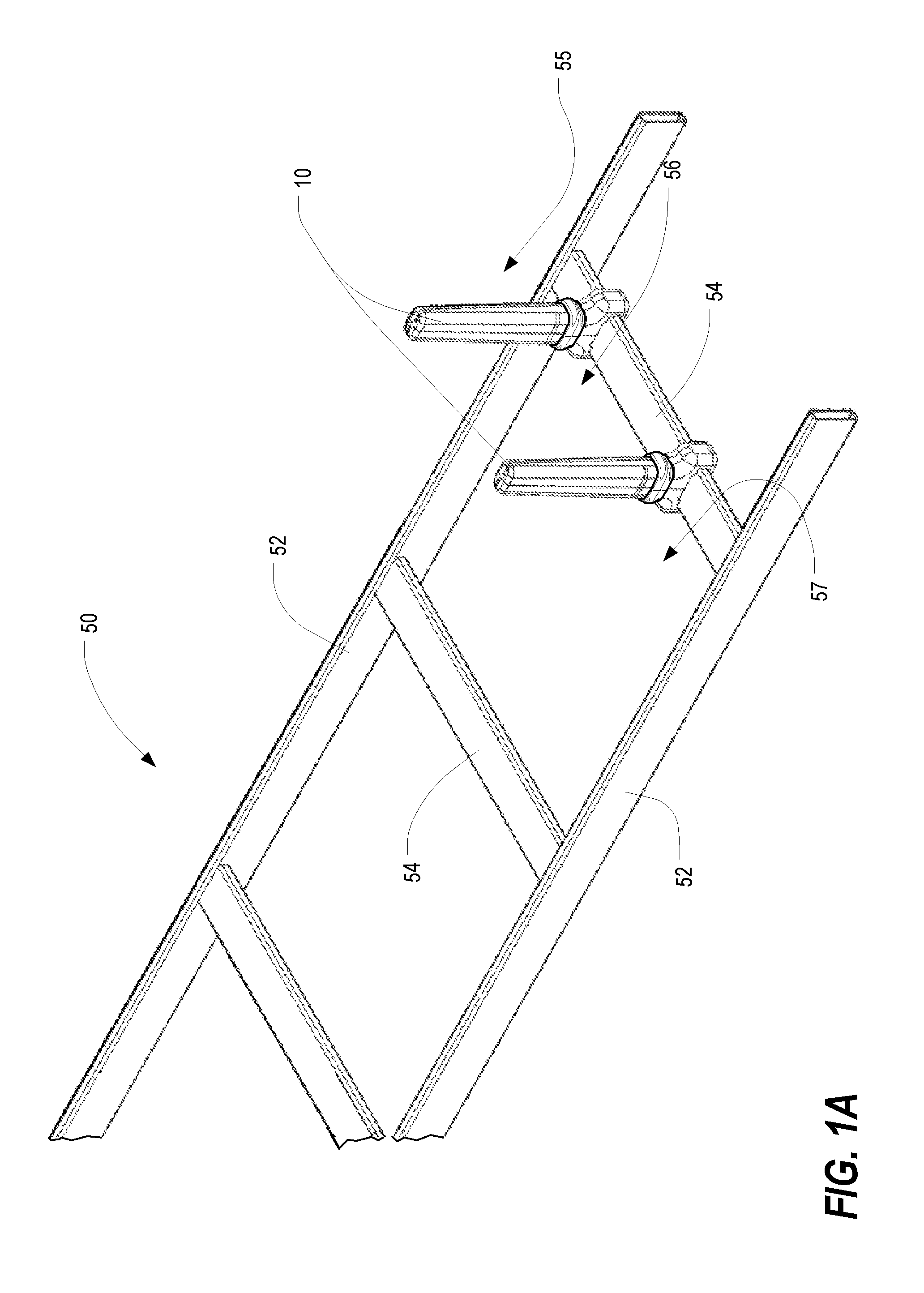
FIG. 1A is an isometric view of a pair of cable pathway dividers 10 in accordance with one or more preferred embodiments of the present invention, shown installed on a cable runway 50. As shown in FIG. 1A, the cable runway 50 is generally produced from a pair of spaced-apart parallel rails 52 and a plurality of transverse cross members 54 that interconnect the rails 52 at various intervals. Although not required, it is contemplated that the transverse cross members 54 are located at generally evenly-spaced intervals. The two cable pathway dividers 10 are installed on one of the transverse cross members 54, but it will be appreciated that cable pathway dividers 10 may be installed on as many different transverse cross members 54 as desired, and that more than or less than two cable pathway dividers 10 may be installed on a particular transverse cross member 54. Each cable pathway divider 10 extends upwardly from the transverse cross member 54 into the space immediately above the cable runway 50.
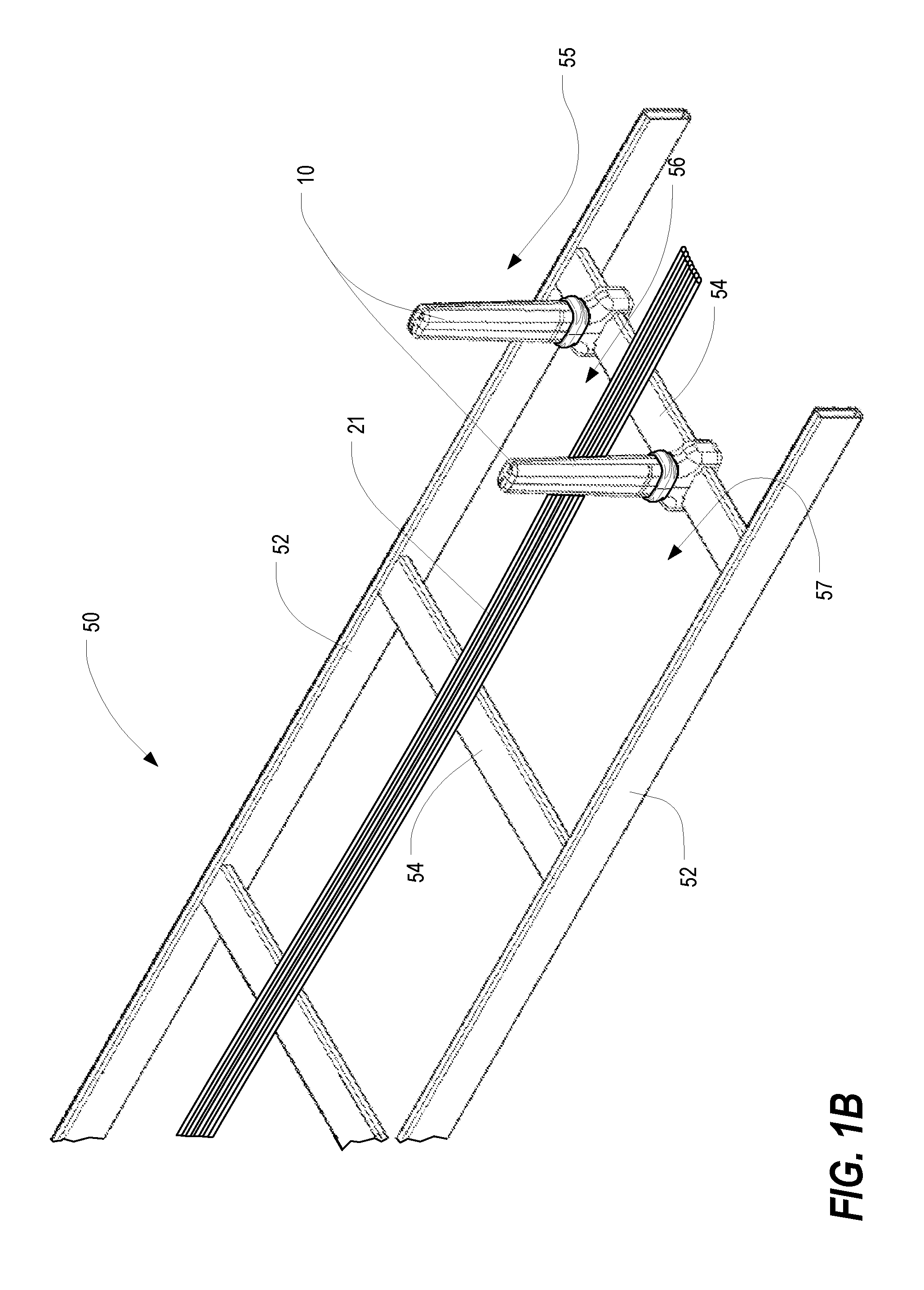
Either alone or in combination with other such dividers installed on other transverse cross members 54, the cable pathway dividers 10 define separate cable pathways on the cable runway 50. In particular, it is contemplated that the two dividers 10 installed on the cable runway of FIG. 1A define up to three distinct cable pathways (i.e., a first cable pathway 55 to the right of a first of the two dividers 10, a second cable pathway 56 between the two dividers 10, and a third cable pathway 57 to the left of the second of the two dividers). Although only two dividers 10 are shown installed in FIG. 1A, it is contemplated that more or less dividers 10 can be installed on a single transverse cross member 54 in order to define the desired quantity of separate cable pathways. Once established by cable pathway dividers 10, each cable pathway 55,56,57 may accommodate one or more cables, including cable bundles, therein. In this regard, FIG. 1B is an isometric view of the arrangement of FIG. 1A, shown with a cable bundle 21 installed between the pair of cable pathway dividers 10 in accordance with one or more preferred embodiments of the present invention. In particular, the cable bundle 21 is installed in the second cable pathway 56 defined by the two cable pathway dividers 10.
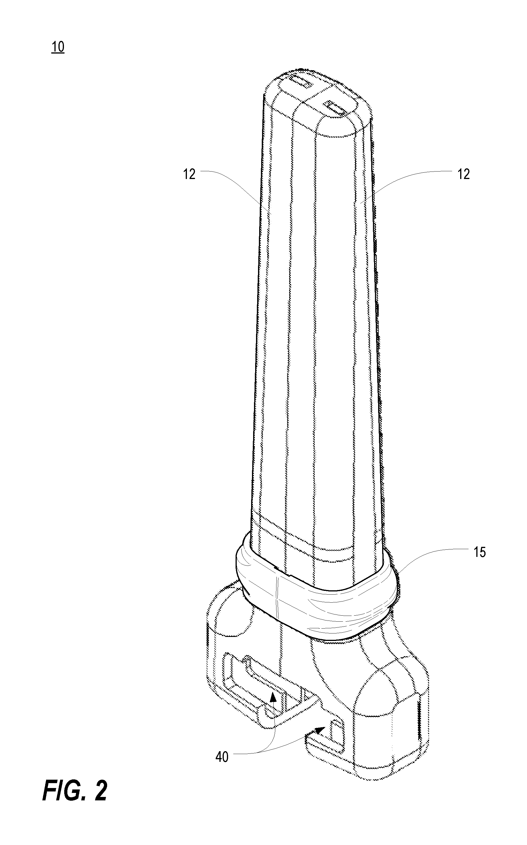
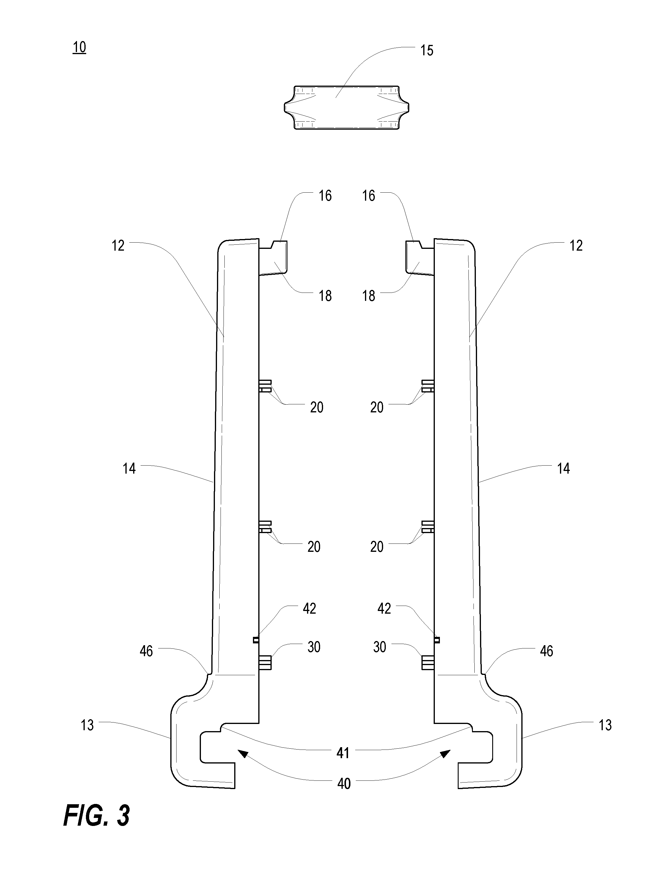
FIG. 2 is an isometric view of one of the cable pathway dividers 10 of FIG. 1A, and FIG. 3 is an exploded top view of the cable pathway divider 10 of FIG. 2. As shown in FIGS. 2 and 3, each cable pathway divider 10 includes a pair of post halves 12 and a separate locking ring 15. The post halves 12 are attachable to one another in a non-permanent manner around a transverse cross member 54 (which is accommodated within the channels 40 defined by the two post halves 12). In a contemplated embodiment, the post halves 12 are identical to one another, at least for the sake of convenience, but it will be appreciated that non-identical post "halves" may be substituted. When the two post halves 12 are coupled or otherwise mated with one another, the locking ring 15 may be slid over the coupled post halves 12 in order to lock the post halves 12 together. As further described hereinbelow, when the post halves 12 are installed on a transverse cross member 54 as shown in FIG. 1A, the locking ring 15 locks the cable pathway divider 10 into position on the transverse cross member 54.
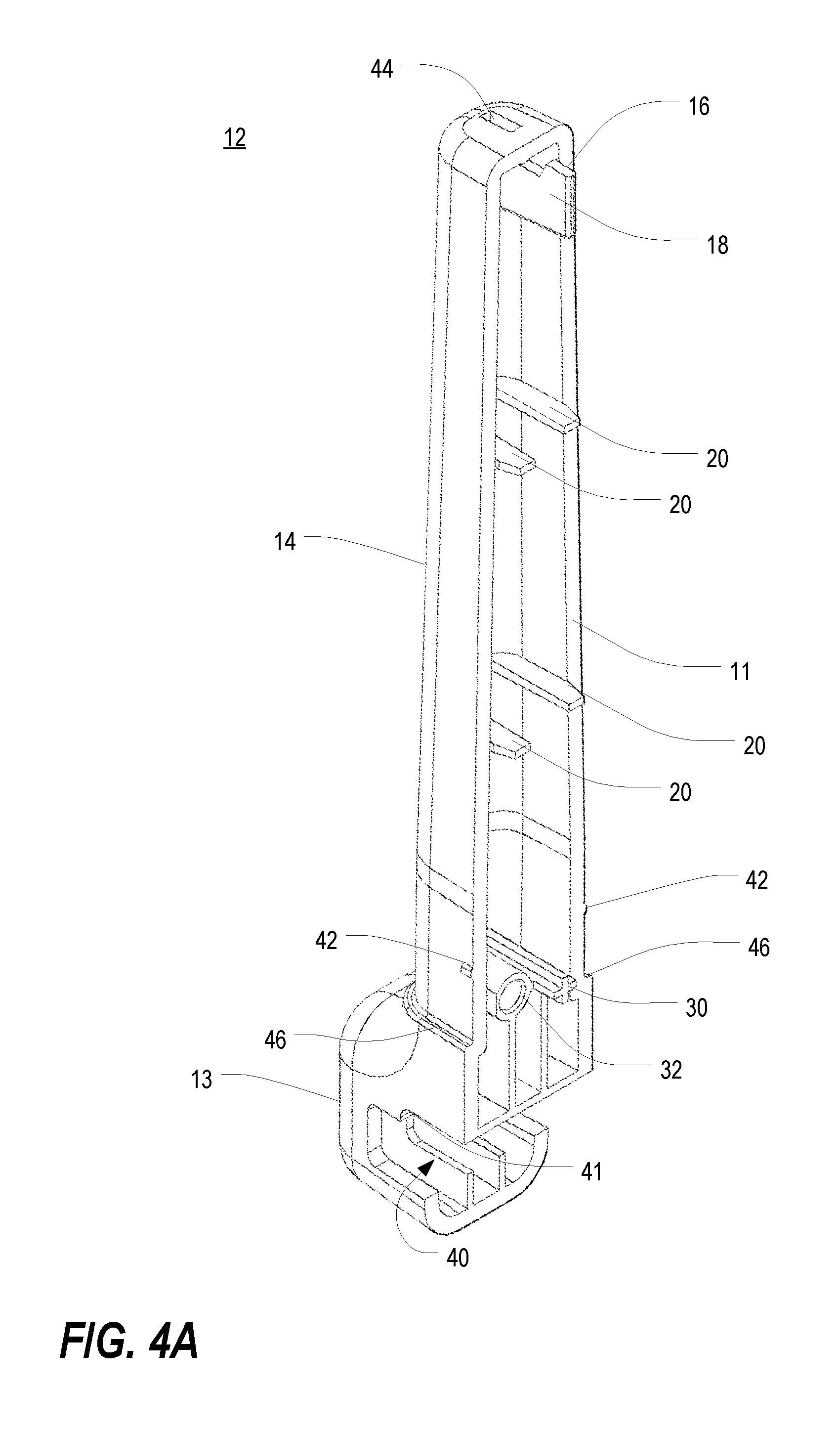
FIGS. 4A and 4B are an isometric view and a front view, respectively, of one post half 12 of the cable pathway divider 10 of FIG. 2. The post half 12 includes a base portion 13 and an extension portion 14 that extends upward from the base portion 13. In at least some embodiments, each post extension portion 14 is tapered slightly such that the extension portion 14 is wider adjacent the base portion 13 and narrower toward its distal end. A ledge 46 is established at the juncture between the extension portion 14 and the base portion 13. In a contemplated embodiment, the base portion 13 and the extension portion 14 are each part of a unitary structure. It is further contemplated that the post halves 12 can be made from a wide variety of different materials. In various contemplated embodiments, the post halves 12 are made from a plastic material. In some such embodiments, the post halves 12 are made using an injection molding process.
As further shown in FIGS. 4A and 4B (and with additional reference to FIG. 3), each post half 12 may be hollow (so as to save on raw material) but includes a peripheral edge surface 11 that is arranged to abut the edge surface 11 of the other post half 12. Alternatively, the post halves 12 may be solid or partially solid. Each post half 12 preferably includes a plurality of alignment tabs 20 that extend beyond the peripheral edge surface 11 of the post half 12 and that help to facilitate alignment of the post halves 12 during the process of installing the divider 10 on a transverse cross member 54. The tabs 20 may be arranged in pairs on the interior of the post half 12, with tabs 20 of each pair arranged along opposite sides of the post half (with one tab 20 of each pair disposed to one side of a center line 75 and the other tab 20 of each pair disposed to the other side of the center line 75). Furthermore, within each pair, the tabs 20 may be slightly offset from one another in the longitudinal direction (i.e., in the direction from the proximal end toward the distal end of the post halves 12). When the post halves 12 are coupled together, as described in greater detail below, each alignment tab 20 from one post half 12 is paired against, and can at least slightly overlap with, a corresponding alignment tab 20 from the other post half 12. Alignment tabs 20 from each post half 12 abut against one another as the post halves 12 are brought together, thereby helping to facilitate alignment during the installation process. However, it will be appreciated that other alignment structures may be utilized, or in some cases may be omitted (at the potential cost of convenience and/or ease of use).
Each post half 12 also preferably includes a prong 30 and a corresponding socket 32. The prong 30 extends from the interior of the post half 12 and beyond the peripheral edge surface 11 thereof. The socket 32 is disposed adjacent to the prong 30 and is sized to receive the prong 30 of the other post half 12. In order to align the respective prongs 30 and sockets 32, the prong 30 and the socket 32 are also arranged generally at either side of the center line 75 of the post half 12 (with the prong 30 disposed to one side of the center line 75 and at least a majority of the socket 32 disposed to the other side of the center line 75). In this regard, when the post halves 12 are coupled together, the prong 30 of each post half 12 is received within the socket 32 of the other post half 12. Again, in various alternative embodiments, other alignment structures may be alternatively or additionally utilized.
FIG. 5 is a fragmentary top view of portions of the cable runway 50 and a cable pathway divider 10 of FIG. 1A, shown with the post halves 12 of one of the cable pathway dividers 10 in a partially separated state. As shown in FIGS. 2-5, the base portion 13 of each post half 12 includes an open-sided channel 40 extending all the way therethrough. When the post halves 12 are coupled together during the installation process, the base portions 13 of each post half 12 are brought together around the transverse cross member 54, which is received within the combined channels 40. When the post halves 12 are arranged adjacent to one another with the respective channels 40 facing each other, the combined channels 40 are sized and shaped to accommodate one or more different transverse cross members 54. In particular, the combined channels 40 of the post halves 12 are well-suited to accommodate transverse cross members 54 of varying sizes and cross-sectional shapes, as will be explained in further detail below.
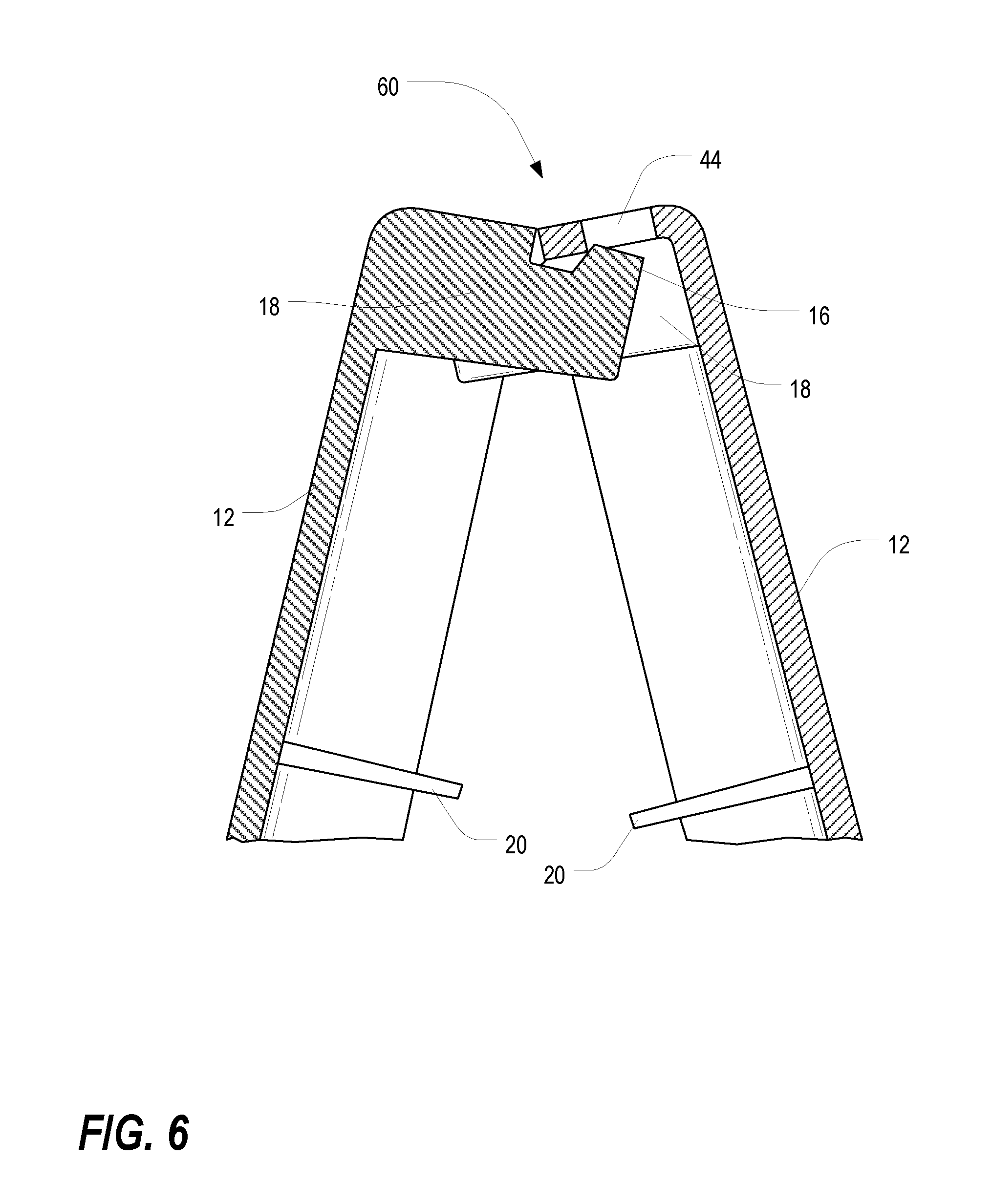
FIG. 6 is an enlarged fragmentary cross-sectional view of portions of the two post halves 12 of the cable pathway divider 10 of FIG. 5, illustrating a hinge mechanism 60 established therebetween. With reference to FIGS. 3-6, the pair of post halves 12 can be hinged to one another at their distal ends and then brought together around a transverse cross member 54 of the cable runway 50. As perhaps best seen in FIGS. 3 and 4A, each post half 12 includes a hinge member 18 with a tab 16 extending upwardly away therefrom. Additionally, as perhaps best seen in FIGS. 4A and 4B, each post half 12 includes a slot 44 disposed in the distal (i.e., top) end of the extension portion 14. As with the prong 30 and the socket 32 discussed previously, the hinge member tab 16 and the slot 44 are each slightly off from the center line 75 of the post half 12 (with the hinge member 18 and tab 16 disposed to one side of the center line 75 and the slot 44 disposed to the other side of the center line 75).
During installation of the cable pathway divider 10, the extension portions 14 of the two post halves 12 are brought together and engaged so that the tab 16 of each post half 12 is positioned within the slot 44 of the other post half 12 in an interlocking manner (as perhaps best seen in FIG. 6). Once the post halves 12 are engaged in this manner, the hinge members 18 effectively define a hinge mechanism 60, and the base portions 13 of the two post halves 12 can be brought together around a transverse cross member 54 of the cable runway 50 (as perhaps best seen in FIG. 5). As the base portions 13 are brought together, the alignment tabs 20 of the post halves 12 abut one another in order to help align the post halves 12 in an appropriate installation position. Additionally, the prong 30 of each post half 12 is received within the socket 32 of the other post half 12.
It will be appreciated that in embodiments in which the post halves are not identical to each other, a slot 44 may be provided in only one such post half and a hinge member tab 16 may be provided in only the other such post half. Furthermore, it will be appreciated that other hinge mechanisms, such as barrel hinges, pivot hinges, gate hinges, and the like, may be alternatively or additionally utilized.
As noted previously, the channels 40 of the base portions 13 are sized to correspond with and receive, when arranged adjacent to and facing each other, the cross sectional shape of the transverse cross member 54. Once the post halves 12 are coupled to one another (with the transverse cross member 54 received in the channels 40 between the respective base portions 13), the locking ring 15 can be installed to clamp the post halves 12 together. In this regard, FIG. 7 is an isometric view of the locking ring 15 of the cable pathway divider 10 of FIG. 2, and FIG. 8 is an isometric view of the cable pathway dividers 10 and cable runway 50 of FIG. 1A, shown with the locking ring 15 of one of the dividers 10 being installed and/or removed from the post halves 12.
As shown in FIG. 7, the locking ring 15 includes a sidewall 70 that defines an opening 76 for receiving the post halves 12 of the cable pathway divider 10. In a contemplated embodiment, the locking ring 15 is made from a plastic material. The inner surfaces of the sidewall 70 include a plurality of recesses 72 to facilitate locking engagement with the post halves 12. In at least some embodiments, recesses 72 are located at opposite sides of the sidewall 70 at both upper and lower edges thereof. With recesses 72 being located at both upper and lower edges of the sidewall 70, it is contemplated that the locking ring 15 does not necessarily have a pre-established upward/downward orientation for installation on the post halves 12 (i.e., the locking ring 15 can be installed on the post halves 12 in the orientation shown in FIG. 7 or alternatively can be installed in an inverted orientation).
As further shown in FIG. 7, the sidewall 70 preferably includes grips 74 disposed at opposite exterior-facing sides thereof. The grips 74 are shown as tapered sections of the sidewall 70 (that taper outwardly from upper and lower edges of the sidewall 70). In this regard, the grips 74 define an area against which a user can position his or her fingers (at either or both sides of the locking ring 15) in order to push the locking ring 15 downward onto the post halves 12.
As perhaps best illustrated in FIGS. 3, 4A and 8, each post half 12 includes one or more retaining bosses 42 along the side thereof and near the proximal end of the extension portion 14. Once the post halves 12 are coupled to one another, as discussed above, the locking ring 15 can be fit over the distal ends of the post halves 12 and pushed downward toward the ledges 46 of the post halves. Because the post halves 12 are slightly tapered toward the distal ends thereof, it is contemplated that the locking ring 15 can be fit over the distal ends of the post halves 12 with relative ease. Then, as the post halves 12 become wider toward the proximal ends thereof, a greater pushing force may be required. In this regard, the grips 74 of the locking ring 15 provide a surface and/or structure upon which a downward pushing force can be applied, particularly as the extension portions 14 becomes wider at the proximal end thereof and as the bottom of the locking ring 15 encounters the retaining bosses 42 and must be pushed past them.
Once the bottom of the locking ring 15 has been pushed past the retaining bosses 42 and into abutment with the ledges 46 of the post halves 12, the retaining bosses 42 of the post halves 12 engage with the corresponding recesses 72 along the upper edge of the locking ring 15. (As noted previously, the recesses 72 along the bottom edge of the ring are provided so that the ring 15 may function in an inverted orientation.) When the retaining bosses 42 are engaged with the recesses 72, the locking ring 15 is retained in place (i.e., locked) at the proximal end of the extension portions 14 between the ledges 46 and the retaining bosses 42. In this regard, the locking ring 15 clamps the post halves 12 to the transverse cross member 54 and effectively locks the cable pathway divider 10 tightly into position on the cable runway 50. It is contemplated that the opening 76 in the locking ring 15 can be sized, relative to the cross-sectional shape of the post halves 12 at the proximal end of the extension portions 14, in order to provide a tight fit and thereby ensure that the locking ring 15 clamps the post halves 12 tightly onto the transverse cross member 54. In the locked state, the extension portions 14 of the post halves 12 extend upwardly into the space above the cable runway 50 in order to help define two or more separate cable pathways.
In at least some embodiments, the channels 40 of the post halves 12 (and, thus, of the base portion 13 of each cable pathway divider 10 as a whole) are sized and shaped to fit around transverse cross members 54 of different cross-sectional shapes or geometries. In this regard, FIG. 9 is a fragmentary front view of the cable pathway divider 10 of FIG. 2 shown installed on a transverse cross member 54 of a first cross-sectional geometry, FIG. 10 is a fragmentary front view of the cable pathway divider 10 of FIG. 2 shown installed on a transverse cross member 154 of a second cross-sectional geometry, and FIG. 11 is a fragmentary front view of the cable pathway divider 10 of FIG. 2 shown installed on a transverse cross member 254 of a third cross-sectional geometry. In particular, the transverse cross member of FIG. 9 is an industry-standard crossbar sometimes referred to as a "universal crossbar," the transverse cross member in FIG. 10 is an industry-standard crossbar sometimes referred to as a "UL crossbar," and the transverse cross member in FIG. 11 is an extruded aluminum crossbar offered by Chatsworth Products, Inc. of Westlake Village, Calif.
As generally shown in FIGS. 9-11, it is contemplated that a cable pathway divider 10 in accordance with one or more preferred embodiments of the present invention can be installed on a wide variety of different transverse cross members 54,154,254 of a cable runway 50. In each case, the channels 40 within the base portions 13 of the respective post halves 12 include features that facilitate accommodation of different types of accepted cross members commonly used with cable runways. In particular, it is contemplated that a single pair of identical post halves 12 can include channels 40 capable of accommodating cross members 54,154,254 of varying cross-sectional shapes or geometries. As shown in FIG. 9, the universal crossbar 54 includes an elongated generally rectangular cross-sectional shape. As shown in FIG. 10, the UL crossbar 154 includes a generally rectangular cross-sectional shape that is not as elongated as that of the universal crossbar of FIG. 9. In this regard, the channels 40, include notches 41 to accommodate the shorter rectangular shape of the UL crossbar 154. A better view of the notches 41 of the channels can be seen in FIGS. 3 and 4A. As shown in FIG. 11, the extruded aluminum cross bar 254 includes an elongated generally rectangular shape similar to the universal crossbar 54 of FIG. 9, but with an additional extruded portion that extends through a gap 43 defined between the base portions 13 of the post halves 12.
As discussed herein, a cable pathway divider 10 in accordance with one or more preferred embodiments of the present invention is capable of quick and easy installation on a transverse cross member 54,154,254 of a cable runway without the aid of tools. It is further contemplated, that such a cable pathway divider 10 is capable of removal and re-installation in a different location with relative ease, thereby helping to facilitate easy customization of a cable runway 50 to suit a particular set of cabling requirements.
Based on the foregoing information, it will be readily understood by those persons skilled in the art that the present invention is susceptible of broad utility and application. Many embodiments and adaptations of the present invention other than those specifically described herein, as well as many variations, modifications, and equivalent arrangements, will be apparent from or reasonably suggested by the present invention and the foregoing descriptions thereof, without departing from the substance or scope of the present invention.
Accordingly, while the present invention has been described herein in detail in relation to one or more preferred embodiments, it is to be understood that this disclosure is only illustrative and exemplary of the present invention and is made merely for the purpose of providing a full and enabling disclosure of the invention. The foregoing disclosure is not intended to be construed to limit the present invention or otherwise exclude any such other embodiments, adaptations, variations, modifications or equivalent arrangements; the present invention being limited only by the claims appended hereto and the equivalents thereof.
* * * * *
D00000
D00001
D00002
D00003
D00004
D00005
D00006
D00007
D00008
D00009
D00010
D00011
XML
uspto.report is an independent third-party trademark research tool that is not affiliated, endorsed, or sponsored by the United States Patent and Trademark Office (USPTO) or any other governmental organization. The information provided by uspto.report is based on publicly available data at the time of writing and is intended for informational purposes only.
While we strive to provide accurate and up-to-date information, we do not guarantee the accuracy, completeness, reliability, or suitability of the information displayed on this site. The use of this site is at your own risk. Any reliance you place on such information is therefore strictly at your own risk.
All official trademark data, including owner information, should be verified by visiting the official USPTO website at www.uspto.gov. This site is not intended to replace professional legal advice and should not be used as a substitute for consulting with a legal professional who is knowledgeable about trademark law.