Dynamic guest image creation and rollback
Goradia
U.S. patent number 10,242,185 [Application Number 14/222,524] was granted by the patent office on 2019-03-26 for dynamic guest image creation and rollback. This patent grant is currently assigned to FireEye, Inc.. The grantee listed for this patent is FireEye, Inc.. Invention is credited to Harnish Goradia.


View All Diagrams
| United States Patent | 10,242,185 |
| Goradia | March 26, 2019 |
Dynamic guest image creation and rollback
Abstract
According to one embodiment, a computerized method comprises three operations. First, an incoming object is analyzed to determine if the incoming object is suspicious by having characteristics that suggest the object is an exploit. Next, a virtual machine is dynamically configured with a software image representing a current operating state of a targeted client device. The software image represents content and structure of a storage volume for the targeted client device at a time of configuring the virtual machine. Lastly, the object is processed by the virtual machine in order to detect any anomalous behaviors that may cause the object to be classified as an exploit.
| Inventors: | Goradia; Harnish (Milpitas, CA) | ||||||||||
|---|---|---|---|---|---|---|---|---|---|---|---|
| Applicant: |
|
||||||||||
| Assignee: | FireEye, Inc. (Milpitas,
CA) |
||||||||||
| Family ID: | 65811621 | ||||||||||
| Appl. No.: | 14/222,524 | ||||||||||
| Filed: | March 21, 2014 |
| Current U.S. Class: | 1/1 |
| Current CPC Class: | G06F 21/566 (20130101); G06F 21/552 (20130101) |
| Current International Class: | G06F 21/55 (20130101) |
References Cited [Referenced By]
U.S. Patent Documents
| 4292580 | September 1981 | Ott et al. |
| 5175732 | December 1992 | Hendel et al. |
| 5440723 | August 1995 | Arnold et al. |
| 5490249 | February 1996 | Miller |
| 5657473 | August 1997 | Killean et al. |
| 5842002 | November 1998 | Schnurer et al. |
| 5978917 | November 1999 | Chi |
| 6088803 | July 2000 | Tso et al. |
| 6094677 | July 2000 | Capek et al. |
| 6108799 | August 2000 | Boulay et al. |
| 6118382 | September 2000 | Hibbs et al. |
| 6269330 | July 2001 | Cidon et al. |
| 6272641 | August 2001 | Ji |
| 6279113 | August 2001 | Vaidya |
| 6298445 | October 2001 | Shostack |
| 6357008 | March 2002 | Nachenberg |
| 6417774 | July 2002 | Hibbs et al. |
| 6424627 | July 2002 | Sorhaug et al. |
| 6442696 | August 2002 | Wray et al. |
| 6484315 | November 2002 | Ziese |
| 6487666 | November 2002 | Shanklin et al. |
| 6493756 | December 2002 | O'Brien et al. |
| 6550012 | April 2003 | Villa et al. |
| 6700497 | March 2004 | Hibbs et al. |
| 6775657 | August 2004 | Baker |
| 6831893 | December 2004 | Ben Nun et al. |
| 6832367 | December 2004 | Choi et al. |
| 6895550 | May 2005 | Kanchirayappa et al. |
| 6898632 | May 2005 | Gordy et al. |
| 6907396 | June 2005 | Muttik et al. |
| 6941348 | September 2005 | Petry et al. |
| 6971097 | November 2005 | Wallman |
| 6981279 | December 2005 | Arnold et al. |
| 6995665 | February 2006 | Appelt et al. |
| 7007107 | February 2006 | Ivchenko et al. |
| 7028179 | April 2006 | Anderson et al. |
| 7043757 | May 2006 | Hoefelmeyer et al. |
| 7069316 | June 2006 | Gryaznov |
| 7080407 | July 2006 | Zhao et al. |
| 7080408 | July 2006 | Pak et al. |
| 7093002 | August 2006 | Wolff et al. |
| 7093239 | August 2006 | van der Made |
| 7096498 | August 2006 | Judge |
| 7100201 | August 2006 | Izatt |
| 7107617 | September 2006 | Hursey et al. |
| 7159149 | January 2007 | Spiegel et al. |
| 7213260 | May 2007 | Judge |
| 7231667 | June 2007 | Jordan |
| 7240364 | July 2007 | Branscomb et al. |
| 7240368 | July 2007 | Roesch et al. |
| 7243371 | July 2007 | Kasper et al. |
| 7249175 | July 2007 | Donaldson |
| 7287278 | October 2007 | Liang |
| 7308716 | December 2007 | Danford et al. |
| 7328453 | February 2008 | Merkle, Jr. et al. |
| 7346486 | March 2008 | Ivancic et al. |
| 7356736 | April 2008 | Natvig |
| 7386888 | June 2008 | Liang et al. |
| 7392542 | June 2008 | Bucher |
| 7418729 | August 2008 | Szor |
| 7428300 | September 2008 | Drew et al. |
| 7441272 | October 2008 | Durham et al. |
| 7448084 | November 2008 | Apap et al. |
| 7458098 | November 2008 | Judge et al. |
| 7464404 | December 2008 | Carpenter et al. |
| 7464407 | December 2008 | Nakae et al. |
| 7467408 | December 2008 | O'Toole, Jr. |
| 7478428 | January 2009 | Thomlinson |
| 7480773 | January 2009 | Reed |
| 7487543 | February 2009 | Arnold et al. |
| 7496960 | February 2009 | Chen et al. |
| 7496961 | February 2009 | Zimmer et al. |
| 7519990 | April 2009 | Xie |
| 7523493 | April 2009 | Liang et al. |
| 7530104 | May 2009 | Thrower et al. |
| 7540025 | May 2009 | Tzadikario |
| 7565550 | July 2009 | Liang et al. |
| 7568233 | July 2009 | Szor et al. |
| 7584455 | September 2009 | Ball |
| 7603715 | October 2009 | Costa et al. |
| 7607171 | October 2009 | Marsden et al. |
| 7639714 | December 2009 | Stolfo et al. |
| 7644441 | January 2010 | Schmid et al. |
| 7657419 | February 2010 | van der Made |
| 7676841 | March 2010 | Sobchuk et al. |
| 7698548 | April 2010 | Shelest et al. |
| 7707633 | April 2010 | Danford et al. |
| 7712136 | May 2010 | Sprosts et al. |
| 7730011 | June 2010 | Deninger et al. |
| 7739740 | June 2010 | Nachenberg et al. |
| 7779463 | August 2010 | Stolfo et al. |
| 7784097 | August 2010 | Stolfo et al. |
| 7832008 | November 2010 | Kraemer |
| 7836502 | November 2010 | Zhao et al. |
| 7849506 | December 2010 | Dansey et al. |
| 7854007 | December 2010 | Sprosts et al. |
| 7869073 | January 2011 | Oshima |
| 7877803 | January 2011 | Enstone et al. |
| 7904959 | March 2011 | Sidiroglou et al. |
| 7908653 | March 2011 | Brickell |
| 7908660 | March 2011 | Bahl |
| 7930738 | April 2011 | Petersen |
| 7937761 | May 2011 | Benett |
| 7949849 | May 2011 | Lowe et al. |
| 7996556 | August 2011 | Raghavan et al. |
| 7996836 | August 2011 | McCorkendale et al. |
| 7996904 | August 2011 | Chiueh et al. |
| 7996905 | August 2011 | Arnold et al. |
| 8006305 | August 2011 | Aziz |
| 8010667 | August 2011 | Zhang et al. |
| 8020206 | September 2011 | Hubbard et al. |
| 8028338 | September 2011 | Schneider et al. |
| 8042184 | October 2011 | Batenin |
| 8045094 | October 2011 | Teragawa |
| 8045458 | October 2011 | Alperovitch et al. |
| 8069484 | November 2011 | McMillan et al. |
| 8087086 | December 2011 | Lai et al. |
| 8171553 | May 2012 | Aziz et al. |
| 8176049 | May 2012 | Deninger et al. |
| 8176480 | May 2012 | Spertus |
| 8201246 | June 2012 | Wu et al. |
| 8204984 | June 2012 | Aziz et al. |
| 8214905 | July 2012 | Doukhvalov et al. |
| 8220055 | July 2012 | Kennedy |
| 8225288 | July 2012 | Miller et al. |
| 8225373 | July 2012 | Kraemer |
| 8233882 | July 2012 | Rogel |
| 8234640 | July 2012 | Fitzgerald et al. |
| 8234709 | July 2012 | Viljoen et al. |
| 8239944 | August 2012 | Nachenberg et al. |
| 8260750 | September 2012 | Gugick |
| 8260914 | September 2012 | Ranjan |
| 8266091 | September 2012 | Gubin et al. |
| 8286251 | October 2012 | Eker et al. |
| 8291499 | October 2012 | Aziz et al. |
| 8296848 | October 2012 | Griffin |
| 8307435 | November 2012 | Mann et al. |
| 8307443 | November 2012 | Wang et al. |
| 8312545 | November 2012 | Tuvell et al. |
| 8321936 | November 2012 | Green et al. |
| 8321941 | November 2012 | Tuvell et al. |
| 8332571 | December 2012 | Edwards, Sr. |
| 8365286 | January 2013 | Poston |
| 8365297 | January 2013 | Parshin et al. |
| 8370938 | February 2013 | Daswani et al. |
| 8370939 | February 2013 | Zaitsev et al. |
| 8375444 | February 2013 | Aziz et al. |
| 8381299 | February 2013 | Stolfo et al. |
| 8402529 | March 2013 | Green et al. |
| 8464340 | June 2013 | Ahn et al. |
| 8479174 | July 2013 | Chiriac |
| 8479276 | July 2013 | Vaystikh et al. |
| 8479291 | July 2013 | Bodke |
| 8510827 | August 2013 | Leake et al. |
| 8510828 | August 2013 | Guo et al. |
| 8510842 | August 2013 | Amit et al. |
| 8516478 | August 2013 | Edwards et al. |
| 8516590 | August 2013 | Ranadive et al. |
| 8516593 | August 2013 | Aziz |
| 8522348 | August 2013 | Chen et al. |
| 8528086 | September 2013 | Aziz |
| 8533824 | September 2013 | Hutton et al. |
| 8539582 | September 2013 | Aziz et al. |
| 8549638 | October 2013 | Aziz |
| 8555391 | October 2013 | Demir et al. |
| 8561177 | October 2013 | Aziz et al. |
| 8566946 | October 2013 | Aziz et al. |
| 8584094 | November 2013 | Dahdia et al. |
| 8584234 | November 2013 | Sobel et al. |
| 8584239 | November 2013 | Aziz et al. |
| 8595834 | November 2013 | Xie et al. |
| 8612971 | December 2013 | Fitzgerald |
| 8627476 | January 2014 | Satish et al. |
| 8635696 | January 2014 | Aziz |
| 8682054 | March 2014 | Xue et al. |
| 8682812 | March 2014 | Ranjan |
| 8689333 | April 2014 | Aziz |
| 8695096 | April 2014 | Zhang |
| 8713631 | April 2014 | Pavlyushchik |
| 8713681 | April 2014 | Silberman et al. |
| 8726392 | May 2014 | McCorkendale et al. |
| 8739280 | May 2014 | Chess et al. |
| 8776229 | July 2014 | Aziz |
| 8782792 | July 2014 | Bodke |
| 8789172 | July 2014 | Stolfo et al. |
| 8789178 | July 2014 | Kejriwal et al. |
| 8793787 | July 2014 | Ismael et al. |
| 8805947 | August 2014 | Kuzkin et al. |
| 8806647 | August 2014 | Daswani et al. |
| 8832829 | September 2014 | Manni et al. |
| 8850570 | September 2014 | Ramzan |
| 8850571 | September 2014 | Staniford et al. |
| 8881234 | November 2014 | Narasimhan et al. |
| 8881282 | November 2014 | Aziz et al. |
| 8898788 | November 2014 | Aziz et al. |
| 8910156 | December 2014 | Kenchammana-Hosekote |
| 8935779 | January 2015 | Manni et al. |
| 8984638 | March 2015 | Aziz et al. |
| 8990939 | March 2015 | Staniford et al. |
| 8990944 | March 2015 | Singh et al. |
| 8997219 | March 2015 | Staniford |
| 9009822 | April 2015 | Ismael et al. |
| 9009823 | April 2015 | Ismael et al. |
| 9027135 | May 2015 | Aziz |
| 9071638 | June 2015 | Aziz et al. |
| 9104867 | August 2015 | Thioux et al. |
| 9106694 | August 2015 | Aziz et al. |
| 9118715 | August 2015 | Staniford et al. |
| 9159035 | October 2015 | Ismael et al. |
| 9171160 | October 2015 | Vincent et al. |
| 9176843 | November 2015 | Ismael et al. |
| 9189627 | November 2015 | Islam |
| 9195829 | November 2015 | Goradia et al. |
| 9225740 | December 2015 | Ismael et al. |
| 9233972 | January 2016 | Itov et al. |
| 9241010 | January 2016 | Bennett et al. |
| 9251343 | February 2016 | Vincent et al. |
| 9262635 | February 2016 | Paithane et al. |
| 9282109 | March 2016 | Aziz et al. |
| 9292686 | March 2016 | Ismael et al. |
| 9294501 | March 2016 | Mesdaq et al. |
| 9300686 | March 2016 | Pidathala et al. |
| 9306960 | April 2016 | Aziz |
| 9306974 | April 2016 | Aziz et al. |
| 9311479 | April 2016 | Manni et al. |
| 9355247 | May 2016 | Thioux et al. |
| 9356944 | May 2016 | Aziz |
| 9363280 | June 2016 | Rivlin et al. |
| 9367681 | June 2016 | Ismael et al. |
| 9398028 | July 2016 | Karandikar et al. |
| 2001/0005889 | June 2001 | Albrecht |
| 2001/0047326 | November 2001 | Broadbent et al. |
| 2002/0018903 | February 2002 | Kokubo et al. |
| 2002/0038430 | March 2002 | Edwards et al. |
| 2002/0091819 | July 2002 | Melchione et al. |
| 2002/0095607 | July 2002 | Lin-Hendel |
| 2002/0116627 | August 2002 | Tarbotton et al. |
| 2002/0144156 | October 2002 | Copeland, III |
| 2002/0162015 | October 2002 | Tang |
| 2002/0166063 | November 2002 | Lachman et al. |
| 2002/0169952 | November 2002 | DiSanto et al. |
| 2002/0184528 | December 2002 | Shevenell et al. |
| 2002/0188887 | December 2002 | Largman et al. |
| 2002/0194490 | December 2002 | Halperin et al. |
| 2003/0074578 | April 2003 | Ford et al. |
| 2003/0084318 | May 2003 | Schertz |
| 2003/0101381 | May 2003 | Mateev et al. |
| 2003/0115483 | June 2003 | Liang |
| 2003/0188190 | October 2003 | Aaron et al. |
| 2003/0191957 | October 2003 | Hypponen et al. |
| 2003/0200460 | October 2003 | Morota et al. |
| 2003/0212902 | November 2003 | Van Der Made |
| 2003/0229801 | December 2003 | Kouznetsov et al. |
| 2003/0237000 | December 2003 | Denton et al. |
| 2004/0003323 | January 2004 | Bennett et al. |
| 2004/0015712 | January 2004 | Szor |
| 2004/0019832 | January 2004 | Arnold et al. |
| 2004/0047356 | March 2004 | Bauer |
| 2004/0083408 | April 2004 | Spiegel et al. |
| 2004/0088581 | May 2004 | Brawn et al. |
| 2004/0093513 | May 2004 | Cantrell et al. |
| 2004/0111531 | June 2004 | Staniford et al. |
| 2004/0117478 | June 2004 | Triulzi et al. |
| 2004/0117624 | June 2004 | Brandt et al. |
| 2004/0128355 | July 2004 | Chao et al. |
| 2004/0165588 | August 2004 | Pandya |
| 2004/0236963 | November 2004 | Danford et al. |
| 2004/0243349 | December 2004 | Greifeneder et al. |
| 2004/0249911 | December 2004 | Alkhatib et al. |
| 2004/0255161 | December 2004 | Cavanaugh |
| 2004/0268147 | December 2004 | Wiederin et al. |
| 2005/0005159 | January 2005 | Oliphant |
| 2005/0021740 | January 2005 | Bar et al. |
| 2005/0033960 | February 2005 | Vialen et al. |
| 2005/0033989 | February 2005 | Poletto et al. |
| 2005/0050148 | March 2005 | Mohammadioun et al. |
| 2005/0086523 | April 2005 | Zimmer et al. |
| 2005/0091513 | April 2005 | Mitomo et al. |
| 2005/0091533 | April 2005 | Omote et al. |
| 2005/0091652 | April 2005 | Ross et al. |
| 2005/0102297 | May 2005 | Lloyd |
| 2005/0108562 | May 2005 | Khazan et al. |
| 2005/0114663 | May 2005 | Cornell et al. |
| 2005/0125195 | June 2005 | Brendel |
| 2005/0157662 | June 2005 | Bingham et al. |
| 2005/0149726 | July 2005 | Joshi et al. |
| 2005/0183143 | August 2005 | Anderholm et al. |
| 2005/0201297 | September 2005 | Peikari |
| 2005/0210533 | September 2005 | Copeland et al. |
| 2005/0238005 | October 2005 | Chen et al. |
| 2005/0240781 | October 2005 | Gassoway |
| 2005/0262562 | November 2005 | Gassoway |
| 2005/0265331 | December 2005 | Stolfo |
| 2005/0283839 | December 2005 | Cowburn |
| 2006/0010495 | January 2006 | Cohen et al. |
| 2006/0015416 | January 2006 | Hoffman et al. |
| 2006/0015715 | January 2006 | Anderson |
| 2006/0015747 | January 2006 | Van de Ven |
| 2006/0021029 | January 2006 | Brickell et al. |
| 2006/0021054 | January 2006 | Costa et al. |
| 2006/0031476 | February 2006 | Mathes et al. |
| 2006/0047665 | March 2006 | Neil |
| 2006/0070130 | March 2006 | Costea et al. |
| 2006/0075496 | April 2006 | Carpenter et al. |
| 2006/0095968 | May 2006 | Portolani et al. |
| 2006/0101516 | May 2006 | Sudaharan et al. |
| 2006/0101517 | May 2006 | Banzhof et al. |
| 2006/0117385 | June 2006 | Mester et al. |
| 2006/0123477 | June 2006 | Raghavan et al. |
| 2006/0143709 | June 2006 | Brooks et al. |
| 2006/0150249 | July 2006 | Gassen et al. |
| 2006/0161983 | July 2006 | Cothrell et al. |
| 2006/0161987 | July 2006 | Levy-Yurista |
| 2006/0161989 | July 2006 | Reshef et al. |
| 2006/0164199 | July 2006 | Gilde et al. |
| 2006/0173992 | August 2006 | Weber et al. |
| 2006/0179147 | August 2006 | Tran et al. |
| 2006/0184632 | August 2006 | Marino et al. |
| 2006/0191010 | August 2006 | Benjamin |
| 2006/0221956 | October 2006 | Narayan et al. |
| 2006/0236393 | October 2006 | Kramer et al. |
| 2006/0242709 | October 2006 | Seinfeld et al. |
| 2006/0248519 | November 2006 | Jaeger et al. |
| 2006/0248582 | November 2006 | Panjwani et al. |
| 2006/0251104 | November 2006 | Koga |
| 2006/0288417 | December 2006 | Bookbinder et al. |
| 2007/0006225 | January 2007 | McAlister |
| 2007/0006288 | January 2007 | Mayfield et al. |
| 2007/0006313 | January 2007 | Porras et al. |
| 2007/0011174 | January 2007 | Takaragi et al. |
| 2007/0016951 | January 2007 | Piccard et al. |
| 2007/0033645 | February 2007 | Jones |
| 2007/0038943 | February 2007 | FitzGerald et al. |
| 2007/0064689 | March 2007 | Shin et al. |
| 2007/0074169 | March 2007 | Chess et al. |
| 2007/0094730 | April 2007 | Bhikkaji et al. |
| 2007/0101435 | May 2007 | Konanka et al. |
| 2007/0128855 | June 2007 | Cho et al. |
| 2007/0142030 | June 2007 | Sinha et al. |
| 2007/0143827 | June 2007 | Nicodemus et al. |
| 2007/0156895 | July 2007 | Vuong |
| 2007/0157180 | July 2007 | Tillmann et al. |
| 2007/0157306 | July 2007 | Elrod et al. |
| 2007/0168988 | July 2007 | Eisner et al. |
| 2007/0171824 | July 2007 | Ruello et al. |
| 2007/0171921 | July 2007 | Wookey |
| 2007/0174915 | July 2007 | Gribble et al. |
| 2007/0192500 | August 2007 | Lum |
| 2007/0192858 | August 2007 | Lum |
| 2007/0198275 | August 2007 | Malden et al. |
| 2007/0208822 | September 2007 | Wang et al. |
| 2007/0220607 | September 2007 | Sprosts et al. |
| 2007/0240218 | October 2007 | Tuvell et al. |
| 2007/0240219 | October 2007 | Tuvell et al. |
| 2007/0240220 | October 2007 | Tuvell et al. |
| 2007/0240222 | October 2007 | Tuvell et al. |
| 2007/0250930 | October 2007 | Aziz et al. |
| 2007/0256132 | November 2007 | Oliphant |
| 2007/0271446 | November 2007 | Nakamura |
| 2008/0005782 | January 2008 | Aziz |
| 2008/0028463 | January 2008 | Dagon et al. |
| 2008/0032556 | February 2008 | Schreier |
| 2008/0040710 | February 2008 | Chiriac |
| 2008/0046781 | February 2008 | Childs et al. |
| 2008/0066179 | March 2008 | Liu |
| 2008/0072326 | March 2008 | Danford et al. |
| 2008/0077793 | March 2008 | Tan et al. |
| 2008/0080518 | April 2008 | Hoeflin et al. |
| 2008/0086720 | April 2008 | Lekel |
| 2008/0098476 | April 2008 | Syversen |
| 2008/0120722 | May 2008 | Sima et al. |
| 2008/0133208 | June 2008 | Stringham |
| 2008/0134178 | June 2008 | Fitzgerald et al. |
| 2008/0134334 | June 2008 | Kim et al. |
| 2008/0141376 | June 2008 | Clausen et al. |
| 2008/0181227 | July 2008 | Todd |
| 2008/0184373 | July 2008 | Traut et al. |
| 2008/0189787 | August 2008 | Arnold et al. |
| 2008/0201778 | August 2008 | Guo et al. |
| 2008/0209557 | August 2008 | Herley et al. |
| 2008/0215742 | September 2008 | Goldszmidt et al. |
| 2008/0222729 | September 2008 | Chen et al. |
| 2008/0263665 | October 2008 | Ma et al. |
| 2008/0295172 | November 2008 | Bohacek |
| 2008/0301810 | December 2008 | Lehane et al. |
| 2008/0307524 | December 2008 | Singh et al. |
| 2008/0313738 | December 2008 | Enderby |
| 2008/0320594 | December 2008 | Jiang |
| 2009/0003317 | January 2009 | Kasralikar et al. |
| 2009/0007100 | January 2009 | Field et al. |
| 2009/0013408 | January 2009 | Schipka |
| 2009/0031423 | January 2009 | Liu et al. |
| 2009/0036111 | February 2009 | Danford et al. |
| 2009/0037835 | February 2009 | Goldman |
| 2009/0044024 | February 2009 | Oberheide et al. |
| 2009/0044274 | February 2009 | Budko et al. |
| 2009/0064332 | March 2009 | Porras et al. |
| 2009/0077666 | March 2009 | Chen et al. |
| 2009/0083369 | March 2009 | Marmor |
| 2009/0083855 | March 2009 | Apap et al. |
| 2009/0089879 | April 2009 | Wang et al. |
| 2009/0094697 | April 2009 | Provos et al. |
| 2009/0113425 | April 2009 | Ports et al. |
| 2009/0125976 | May 2009 | Wassermann et al. |
| 2009/0126015 | May 2009 | Monastyrsky et al. |
| 2009/0126016 | May 2009 | Sobko et al. |
| 2009/0133125 | May 2009 | Choi et al. |
| 2009/0144823 | June 2009 | Lamastra et al. |
| 2009/0158430 | June 2009 | Borders |
| 2009/0164994 | June 2009 | Vasilevsky |
| 2009/0172815 | July 2009 | Gu et al. |
| 2009/0187992 | July 2009 | Poston |
| 2009/0193293 | July 2009 | Stolfo et al. |
| 2009/0199296 | August 2009 | Xie et al. |
| 2009/0228233 | September 2009 | Anderson et al. |
| 2009/0241187 | September 2009 | Troyansky |
| 2009/0241190 | September 2009 | Todd et al. |
| 2009/0265692 | October 2009 | Godefroid et al. |
| 2009/0271867 | October 2009 | Zhang |
| 2009/0300415 | December 2009 | Zhang et al. |
| 2009/0300761 | December 2009 | Park et al. |
| 2009/0328185 | December 2009 | Berg et al. |
| 2009/0328221 | December 2009 | Blumfield et al. |
| 2010/0005146 | January 2010 | Drako et al. |
| 2010/0011205 | January 2010 | McKenna |
| 2010/0017546 | January 2010 | Poo et al. |
| 2010/0031353 | February 2010 | Thomas et al. |
| 2010/0037314 | February 2010 | Perdisci et al. |
| 2010/0043073 | February 2010 | Kuwamura |
| 2010/0054278 | March 2010 | Stolfo et al. |
| 2010/0058474 | March 2010 | Hicks |
| 2010/0064044 | March 2010 | Nonoyama |
| 2010/0070978 | March 2010 | Chawla |
| 2010/0077481 | March 2010 | Polyakov et al. |
| 2010/0083376 | April 2010 | Pereira et al. |
| 2010/0115621 | May 2010 | Staniford et al. |
| 2010/0122343 | May 2010 | Ghosh |
| 2010/0132038 | May 2010 | Zaitsev |
| 2010/0154056 | June 2010 | Smith et al. |
| 2010/0180344 | July 2010 | Malyshev et al. |
| 2010/0192223 | July 2010 | Ismael et al. |
| 2010/0220863 | September 2010 | Dupaquis et al. |
| 2010/0235831 | September 2010 | Dittmer |
| 2010/0251104 | September 2010 | Massand |
| 2010/0281102 | November 2010 | Chinta et al. |
| 2010/0281541 | November 2010 | Stolfo et al. |
| 2010/0281542 | November 2010 | Stolfo et al. |
| 2010/0287260 | November 2010 | Peterson et al. |
| 2010/0299754 | November 2010 | Amit et al. |
| 2010/0306173 | December 2010 | Frank |
| 2011/0004737 | January 2011 | Greenebaum |
| 2011/0025504 | February 2011 | Lyon et al. |
| 2011/0041179 | February 2011 | Stahlberg |
| 2011/0047594 | February 2011 | Mahaffey et al. |
| 2011/0047620 | February 2011 | Mahaffey et al. |
| 2011/0055907 | March 2011 | Narasimhan et al. |
| 2011/0078794 | March 2011 | Manni et al. |
| 2011/0093951 | April 2011 | Aziz |
| 2011/0099620 | April 2011 | Stavrou et al. |
| 2011/0099633 | April 2011 | Aziz |
| 2011/0113231 | May 2011 | Kaminsky |
| 2011/0145918 | June 2011 | Jung et al. |
| 2011/0145920 | June 2011 | Mahaffey et al. |
| 2011/0145934 | June 2011 | Abramovici et al. |
| 2011/0167493 | July 2011 | Song et al. |
| 2011/0167494 | July 2011 | Bowen et al. |
| 2011/0173460 | July 2011 | Ito et al. |
| 2011/0218966 | September 2011 | Barnes |
| 2011/0219449 | September 2011 | St. Neitzel et al. |
| 2011/0219450 | September 2011 | McDougal et al. |
| 2011/0225624 | September 2011 | Sawhney et al. |
| 2011/0225655 | September 2011 | Niemela et al. |
| 2011/0247072 | October 2011 | Staniford et al. |
| 2011/0265182 | October 2011 | Peinado et al. |
| 2011/0289582 | November 2011 | Kejriwal et al. |
| 2011/0296440 | December 2011 | Laurich |
| 2011/0302587 | December 2011 | Nishikawa et al. |
| 2011/0307954 | December 2011 | Melnik et al. |
| 2011/0307955 | December 2011 | Kaplan et al. |
| 2011/0307956 | December 2011 | Yermakov et al. |
| 2011/0314546 | December 2011 | Aziz et al. |
| 2012/0023593 | January 2012 | Puder et al. |
| 2012/0054869 | March 2012 | Yen et al. |
| 2012/0066466 | March 2012 | Choi |
| 2012/0066698 | March 2012 | Yanoo |
| 2012/0079596 | March 2012 | Thomas et al. |
| 2012/0084859 | April 2012 | Radinsky et al. |
| 2012/0110667 | May 2012 | Zubrilin et al. |
| 2012/0117652 | May 2012 | Manni et al. |
| 2012/0121154 | May 2012 | Xue et al. |
| 2012/0124426 | May 2012 | Maybee et al. |
| 2012/0166818 | June 2012 | Orsini |
| 2012/0174186 | July 2012 | Aziz et al. |
| 2012/0174196 | July 2012 | Bhogavilli et al. |
| 2012/0174218 | July 2012 | McCoy et al. |
| 2012/0198279 | August 2012 | Schroeder |
| 2012/0210423 | August 2012 | Friedrichs et al. |
| 2012/0222121 | August 2012 | Staniford et al. |
| 2012/0255015 | October 2012 | Sahita et al. |
| 2012/0255017 | October 2012 | Sallam |
| 2012/0260342 | October 2012 | Dube et al. |
| 2012/0266244 | October 2012 | Green et al. |
| 2012/0278886 | November 2012 | Luna |
| 2012/0297489 | November 2012 | Dequevy |
| 2012/0330801 | December 2012 | McDougal et al. |
| 2013/0014259 | January 2013 | Gribble et al. |
| 2013/0031548 | January 2013 | Kurozumi |
| 2013/0036472 | February 2013 | Aziz |
| 2013/0047257 | February 2013 | Aziz |
| 2013/0074185 | March 2013 | McDougal et al. |
| 2013/0086684 | April 2013 | Mohler |
| 2013/0097699 | April 2013 | Balupari et al. |
| 2013/0097706 | April 2013 | Titonis et al. |
| 2013/0111587 | May 2013 | Goel et al. |
| 2013/0117852 | May 2013 | Stute |
| 2013/0117855 | May 2013 | Kim et al. |
| 2013/0139264 | May 2013 | Brinkley et al. |
| 2013/0160125 | June 2013 | Likhachev et al. |
| 2013/0160127 | June 2013 | Jeong et al. |
| 2013/0160130 | June 2013 | Mendelev et al. |
| 2013/0160131 | June 2013 | Madou et al. |
| 2013/0167236 | June 2013 | Sick |
| 2013/0174214 | July 2013 | Duncan |
| 2013/0185789 | July 2013 | Hagiwara et al. |
| 2013/0185795 | July 2013 | Winn et al. |
| 2013/0185798 | July 2013 | Saunders et al. |
| 2013/0191915 | July 2013 | Antonakakis et al. |
| 2013/0196649 | August 2013 | Paddon et al. |
| 2013/0212151 | August 2013 | Herbach |
| 2013/0227691 | August 2013 | Aziz et al. |
| 2013/0238673 | September 2013 | Rokuhara |
| 2013/0246370 | September 2013 | Bartram et al. |
| 2013/0246596 | September 2013 | Fujiwara |
| 2013/0263260 | October 2013 | Mahaffey et al. |
| 2013/0291109 | October 2013 | Staniford et al. |
| 2013/0298243 | November 2013 | Kumar et al. |
| 2014/0053260 | February 2014 | Gupta et al. |
| 2014/0053261 | February 2014 | Gupta et al. |
| 2014/0122441 | May 2014 | Vervaet |
| 2014/0130158 | May 2014 | Wang et al. |
| 2014/0137180 | May 2014 | Lukacs et al. |
| 2014/0169762 | June 2014 | Ryu |
| 2014/0179360 | June 2014 | Jackson et al. |
| 2014/0328204 | November 2014 | Klotsche et al. |
| 2014/0337836 | November 2014 | Ismael |
| 2014/0351935 | November 2014 | Shao et al. |
| 2015/0096025 | April 2015 | Ismael |
| 2015/0154042 | June 2015 | Katayama |
| 2439806 | Jan 2008 | GB | |||
| 2490431 | Oct 2012 | GB | |||
| WO-02/06928 | Jan 2002 | WO | |||
| WO-02/23805 | Mar 2002 | WO | |||
| 0206928 | Nov 2003 | WO | |||
| WO-2007-117636 | Oct 2007 | WO | |||
| WO-2008/041950 | Apr 2008 | WO | |||
| WO-2011/084431 | Jul 2011 | WO | |||
| 2011/112348 | Sep 2011 | WO | |||
| 2012/075336 | Jun 2012 | WO | |||
| WO-2012/145066 | Oct 2012 | WO | |||
| 2013/067505 | May 2013 | WO | |||
Other References
|
IEEE Xplore Digital Library Sear Results for "detection of unknown computer worms". Http//ieeexplore.ieee.org/searchresult.jsp?SortField=Score&SortOrder=desc- &ResultC . . . , (Accessed on Aug. 28, 2009). cited by applicant . AltaVista Advanced Search Results. "Event Orchestrator". Http://www.altavista.com/web/results?Itag=ody&pg=aq&aqmode=aqa=Event+Orch- esrator . . . , (Accessed on Sep. 3, 2009). cited by applicant . AltaVista Advanced Search Results. "attack vector identifier". Http://www.altavista.com/web/results?Itag=ody&pg=aq&aqmode=aqa=Event+Orch- estrator . . . , (Accessed on Sep. 15, 2009). cited by applicant . Cisco, Configuring the Catalyst Switched Port Analyzer (SPAN) ("Cisco"), (1992-2003). cited by applicant . Reiner Sailer, Enriquillo Valdez, Trent Jaeger, Roonald Perez, Leendert van Doorn, John Linwood Griffin, Stefan Berger., sHype: Secure Hypervisor Appraoch to Trusted Virtualized Systems (Feb. 2, 2005) ("Sailer"). cited by applicant . Excerpt regarding First Printing Date for Merike Kaeo, Designing Network Security ("Kaeo"), (2005). cited by applicant . The Sniffers's Guide to Raw Traffic available at: yuba.stanford.edu/.about.casado/pcap/section1.html, (Jan. 6, 2014). cited by applicant . NetBIOS Working Group. Protocol Standard for a NetBIOS Service on a TCP/UDP transport: Concepts and Methods. STD 19, RFC 1001, Mar. 1987. cited by applicant . "Network Security: NetDetector--Network Intrusion Forensic System (NIFS) Whitepaper", ("NetDetector Whitepaper"), (2003). cited by applicant . "Packet", Microsoft Computer Dictionary, Microsoft Press, (Mar. 2002), 1 page. cited by applicant . "When Virtual is Better Than Real", IEEEXplore Digital Library, available at, http://ieeexplore.ieee.org/xpl/articleDetails.jsp?reload=true&arnumbe- r=990073, (Dec. 7, 2013). cited by applicant . Abdullah, et al., Visualizing Network Data for Intrusion Detection, 2005 IEEE Workshop on Information Assurance and Security, pp. 100-108. cited by applicant . Adetoye, Adedayo , et al., "Network Intrusion Detection & Response System", ("Adetoye"), (Sep. 2003). cited by applicant . Aura, Tuomas, "Scanning electronic documents for personally identifiable information", Proceedings of the 5th ACM workshop on Privacy in electronic society. ACM, 2006. cited by applicant . Baecher, "The Nepenthes Platform: An Efficient Approach to collect Malware", Springer-verlag Berlin Heidelberg, (2006), pp. 165-184. cited by applicant . Bayer, et al., "Dynamic Analysis of Malicious Code", J Comput Virol, Springer-Verlag, France., (2006), pp. 67-77. cited by applicant . Boubalos, Chris , "extracting syslog data out of raw pcap dumps, seclists.org, Honeypots mailing list archives", available at http://seclists.org/honeypots/2003/q2/319 ("Boubalos"), (Jun. 5, 2003). cited by applicant . Chaudet, C. , et al., "Optimal Positioning of Active and Passive Monitoring Devices", International Conference on Emerging Networking Experiments and Technologies, Proceedings of the 2005 ACM Conference on Emerging Network Experiment and Technology, CoNEXT '05, Toulousse, France, (Oct. 2005), pp. 71-82. cited by applicant . Cohen, M.I. , "PyFlag--An advanced network forensic framework", Digital investigation 5, Elsevier, (2008), pp. S112-S120. cited by applicant . Costa, M. , et al., "Vigilante: End-to-End Containment of Internet Worms", SOSP '05, Association for Computing Machinery, Inc., Brighton U.K., (Oct. 23-26, 2005). cited by applicant . Crandall, J.R. , et al., "Minos:Control Data Attack Prevention Orthogonal to Memory Model", 37th International Symposium on Microarchitecture, Portland, Oregon, (Dec. 2004). cited by applicant . Deutsch, P. , ""Zlib compressed data format specification version 3.3" RFC 1950, (1996)". cited by applicant . Distler, "Malware Analysis: An Introduction", SANS Institute InfoSec Reading Room, SANS Institute, (2007). cited by applicant . Dunlap, George W. , et al., "ReVirt: Enabling Intrusion Analysis through Virtual-Machine Logging and Replay", Proceeding of the 5th Symposium on Operating Systems Design and Implementation, USENIX Association, ("Dunlap"), (Dec. 9, 2002). cited by applicant . Filiol, Eric , et al., "Combinatorial Optimisation of Worm Propagation on an Unknown Network", International Journal of Computer Science 2.2 (2007). cited by applicant . Goel, et al., Reconstructing System State for Intrusion Analysis, Apr. 2008 SIGOPS Operating Systems Review, vol. 42 Issue 3, pp. 21-28. cited by applicant . Hjelmvik, Erik , "Passive Network Security Analysis with NetworkMiner", (IN)Secure, Issue 18, (Oct. 2008), pp. 1-100. cited by applicant . Kaeo, Merike , "Designing Network Security", ("Kaeo"), (Nov. 2003). cited by applicant . Kim, H. , et al., "Autograph: Toward Automated, Distributed Worm Signature Detection", Proceedings of the 13th Usenix Security Symposium (Security 2004), San Diego, (Aug. 2004), pp. 271-286. cited by applicant . King, Samuel T., et al., "Operating System Support for Virtual Machines", ("King"). cited by applicant . Krasnyansky, Max , et al., Universal TUN/TAP driver, available at https://www.kernel.org/doc/Documentation/networking/tuntap.txt_(2002) ("Krasnyansky"). cited by applicant . Kreibich, C. , et al., "Honeycomb-Creating Intrusion Detection Signatures Using Honeypots", 2nd Workshop on Hot Topics in Networks (HotNets-11), Boston, USA, (2003). cited by applicant . Kristoff, J. , "Botnets, Detection and Mitigation: DNS-Based Techniques", NU Security Day, (2005), 23 pages. cited by applicant . Liljenstam, Michael , et al., "Simulating Realistic Network Traffic for Worm Warning System Design and Testing", Institute for Security Technology studies, Dartmouth College, ("Liljenstam"), (Oct. 27, 2003). cited by applicant . Marchette, David J., "Computer Intrusion Detection and Network Monitoring: A Statistical Viewpoint", ("Marchette"), (2001). cited by applicant . Margolis, P.E. , "Random House Webster's `Computer & Internet Dictionary 3rd Edition`", ISBN 0375703519, (Dec. 1998). cited by applicant . Moore, D. , et al., "Internet Quarantine: Requirements for Containing Self-Propagating Code", INFOCOM, vol. 3, (Mar. 30-Apr. 3, 2003), pp. 1901-1910. cited by applicant . Morales, Jose A., et al., ""Analyzing and exploiting network behaviors of malware."", Security and Privacy in Communication Networks. Springer Berlin Heidelberg, 2010. 20-34. cited by applicant . Natvig, Kurt , "Sandboxii: Internet", Virus Bulletin Conference, ("Natvig"), (Sep. 2002). cited by applicant . Newsome, J. , et al., "Dynamic Taint Analysis for Automatic Detection, Analysis, and Signature Generation of Exploits on Commodity Software", In Proceedings of the 12th Annual Network and Distributed System Security, Symposium (NDSS '05), (Feb. 2005). cited by applicant . Newsome, J. , et al., "Polygraph: Automatically Generating Signatures for Polymorphic Worms", In Proceedings of the IEEE Symposium on Security and Privacy, (May 2005). cited by applicant . Nojiri, D. , et al., "Cooperation Response Strategies for Large Scale Attack Mitigation", DARPA Information Survivability Conference and Exposition, vol. 1, (Apr. 22-24, 2003), pp. 293-302. cited by applicant . Peter M. Chen, and Brian D. Noble , "When Virtual Is Better Than Real, Department of Electrical Engineering and Computer Science", University of Michigan ("Chen"). cited by applicant . Silicon Defense, "Worm Containment in the Internal Network", (Mar. 2003), pp. 1-25. cited by applicant . Singh, S. , et al., "Automated Worm Fingerprinting", Proceedings of the ACM/USENIX Symposium on Operating System Design and Implementation, San Francisco, California, (Dec. 2004). cited by applicant . Spitzner, Lance , "Honeypots: Tracking Hackers", ("Spizner"), (Sep. 17, 2002). cited by applicant . Thomas H. Ptacek, and Timothy N. Newsham , "Insertion, Evasion, and Denial of Service: Eluding Network Intrusion Detection", Secure Networks, ("Ptacek"), (Jan. 1998). cited by applicant . Venezia, Paul , "NetDetector Captures Intrusions", InfoWorld Issue 27, ("Venezia"), (Jul. 14, 2003). cited by applicant . Whyte, et al., "DNS-Based Detection of Scanning Works in an Enterprise Network", Proceedings of the 12th Annual Network and Distributed System Security Symposium, (Feb. 2005), 15 pages. cited by applicant . Williamson, Matthew M., "Throttling Viruses: Restricting Propagation to Defeat Malicious Mobile Code", ACSAC Conference, Las Vegas, NV, USA, (Dec. 2002), pp. 1-9. cited by applicant . Adobe Systems Incorporated, "PDF 32000-1:2008, Document management--Portable document format--Part1:PDF 1.7", First Edition, Jul. 1, 2008, 756 pages. cited by applicant . Apostolopoulos, George; hassapis, Constantinos; "V-eM: A cluster of Virtual Machines for Robust, Detailed, and High-Performance Network Emulation", 14th IEEE International Symposium on Modeling, Analysis, and Simulation of Computer and Telecommunication Systems, Sep. 11-14, 2006, pp. 117-126. cited by applicant . Baldi, Mario; Risso, Fulvio; "A Framework for Rapid Development and Portable Execution of Packet-Handling Applications", 5th IEEE International Symposium Processing and Information Technology, Dec. 21, 2005, pp. 233-238. cited by applicant . Cisco "Intrusion Prevention for the Cisco ASA 5500-x Series" Data Sheet (2012). cited by applicant . Clark, John, Sylvian Leblanc,and Scott Knight. "Risks associated with usb hardware trojan devices used by insiders." Systems Conference (SysCon), 2011 IEEE International. IEEE, 2011. cited by applicant . FireEye Malware Analysis & Exchange Network, Malware Protection System, FireEye Inc., 2010. cited by applicant . FireEye Malware Analysis, Modern Malware Forensics, FireEye Inc., 2010. cited by applicant . FireEye v.6.0 Security Target, pp. 1-35, Version 1.1, FireEye Inc., May 2011. cited by applicant . Gibler, Clint, et al. AndroidLeaks: automatically detecting potential privacy leaks in android applications on a large scale. Springer Berlin Heidelberg, 2012. cited by applicant . Gregg Keizer: "Microsoft's HoneyMonkeys Show Patching Windows Works", Aug. 8, 2005, XP055143386, Retrieved from the Internet: URL:https://web.archive.org/web/20121022220617/http://www.informationweek- - .com/microsofts-honeymonkeys-show-patching-wi/167600716 [retrieved on Sep. 29, 2014]. cited by applicant . Heng Yin et al, Panorama: Capturing System-Wide Information Flow for Malware Detection and Analysis, Research Showcase @ CMU, Carnegie Mellon University, 2007. cited by applicant . Idika et al., A-Survey-of-Malware-Detection-Techniques, Feb. 2, 2007, Department of Computer Science, Purdue University. cited by applicant . Isohara, Takamasa, Keisuke Takemori, and Ayumu Kubota. "Kernel-based behavior analysis for android malware detection." Computational intelligence and Security (CIS), 2011 Seventh International Conference on. IEEE, 2011. cited by applicant . Kevin A Roundy et al: "Hybrid Analysis and Control of Malware", Sep. 15, 2010, Recent Advances in Intrusion Detection, Springer Berlin Heidelberg, Berlin, Heidelberg, pp. 317-338, XP019150454 ISBN:978-3-642-15511-6. cited by applicant . Leading Colleges Select FireEye to Stop Malware-Related Data Breaches, FireEye Inc., 2009. cited by applicant . Li et al., A VMM-Based System Call Interposition Framework for Program Monitoring, Dec. 2010, IEEE 16th International Conference on Parallel and Distributed Systems, pp. 706-711. cited by applicant . Lindorfer, Martina, Clemens Kolbitsch, and Paolo Milani Comparetti. "Detecting environment-sensitive malware." Recent Advances in Intrusion Detection. Springer Berlin Heidelberg, 2011. cited by applicant . Lok Kwong et al: "DroidScope: Seamlessly Reconstructing the OS and Dalvik Semantic Views for Dynamic Android Malware Analysis", Aug. 10, 2012, XP055158513, Retrieved from the Internet: URL:https://www.usenix.org/system/files/conference/usenixsecurity12/sec12- - -final107.pdf [retrieved on Dec. 15, 2014]. cited by applicant . Mori, Detecting Unknown Computer Viruses, 2004, Springer-Verlag Berlin Heidelberg. cited by applicant . Oberheide et al., CloudAV.sub.--N-Version Antivirus in the Network Cloud, 17th USENIX Security Symposium USENIX Security '08 Jul. 28-Aug. 1, 2008 San Jose, CA. cited by applicant . U.S. Pat. No. 8,171,553 filed Apr. 20, 2006, Inter Parties Review Decision dated Jul. 10, 2015. cited by applicant . U.S. Pat. No. 8,291,499 filed Mar. 16, 2012, Inter Parties Review Decision dated Jul. 10, 2015. cited by applicant . Wahid et al., Characterising the Evolution in Scanning Activity of Suspicious Hosts, Oct. 2009, Third International Conference on Network and System Security, pp. 344-350. cited by applicant . Yuhei Kawakoya et al: "Memory behavior-based automatic malware unpacking in stealth debugging environment", Malicious and Unwanted Software (Malware), 2010 5th International Conference on, IEEE, Piscataway, NJ, USA, Oct. 19, 2010, pp. 39-46, XP031833827, ISBN:978-1-4244-8-9353-1. cited by applicant . Zhang et al., The Effects of Threading, Infection Time, and Multiple-Attacker Collaboration on Malware Propagation, Sep. 2009, IEEE 28th International Symposium on Reliable Distributed Systems, pp. 73-82. cited by applicant . "White Paper Advanced Threat Protection 1-16 Solution", URL:http://cdn2.hubspot.net/hub/237610/file-232929750-pdf /White_Papers/WP-_Seculert_Solution.pdf, dated Jul. 28, 2013. cited by applicant . Jiyong Jang et al. "BitShred" Computer and Communications Security, ACM, dated (p. 309-320) Oct. 17, 2011. cited by applicant . PCT/US14/55958 filed Sep. 16, 2014 International Search Report and Written Opinion, dated May 1, 2015. cited by applicant . U.S. Appl. No. 14/042,454, filed Sep. 30, 2013 Non-Final Office Action dated Jun. 22, 2015. cited by applicant . U.S. Appl. No. 14/042,454, filed Sep. 30, 2013 Notice of Allowance dated Dec. 21, 2015. cited by applicant. |
Primary Examiner: Gergiso; Techane
Attorney, Agent or Firm: Rutan & Tucker, LLP
Claims
What is claimed is:
1. A computerized method comprising: relating, by a system including the virtual machine having access to information within a Lightweight Directory Access Protocol (LDAP) server, a plurality of master images to a corresponding plurality of groups, each master image representing a base amount of content to be loaded into a client device for use by a member of a particular group of the plurality of groups; automatically generating a software guest image for a targeted client device assigned to or associated with a first group of the plurality of groups in response to a change of storage volume in the targeted client device, the software guest image being based, at least in part, on an image upload message and a prior software guest image of an operating state of the targeted client device that is prior to the change of storage volume, the image upload message includes changes in the operating state of the targeted client device that have occurred after generation of the prior software guest image, the prior software guest image includes either (i) the master image of the first group or (ii) a guest image based on the master image of the first group; dynamically configuring a virtual machine with the software guest image representing a current operating state of the targeted client device, the software guest image representing content and structure of the storage volume for the targeted client device at a time of configuring the virtual machine; and processing an object by the virtual machine in order to detect any anomalous behaviors that may cause the object to be classified as an exploit, the object being data associated with network traffic directed to the targeted client device.
2. The computerized method of claim 1, wherein the object is a plurality of related packets.
3. The computerized method of claim 1, wherein the generating of the software guest image for the targeted client device that is used in configuring the virtual machine prior to processing the object occurs in response to a first polling event based on the change of the storage volume in the targeted client device exceeding a prescribed amount since a prior polling event.
4. The computerized method of claim 1, wherein the generating of the software guest image is further based on the prior software guest image representing a prior operating state of the targeted client device preceding the change of the storage volume.
5. The computerized method of claim 4, wherein the prior software guest image is based on the master image of the first group that includes software and corresponding metadata that is originally loaded into the targeted client device.
6. The computerized method of claim 4, wherein the prior software guest image is based on the guest image that represents software and corresponding metadata stored within the targeted client device at a time preceding the change in storage volume.
7. The computerized method of claim 1, wherein the targeted client device transitions from a non-infected state to an infected state upon receipt and processing of the object having the exploit.
8. The computerized method of claim 7 further comprising: conducting a remediation to restore an operating state of the targeted client device from the infected state to the non-infected state, the remediation includes loading a stored, software guest image associated with the targeted client device prior to targeted client device transitioning from the non-infected state to the infected state.
9. The computerized method of claim 8, wherein the remediation occurs automatically without being prompted by the user.
10. The computerized method of claim 7, wherein responsive to transitioning the targeted client device from the non-infected state to the infected state upon receipt and processing of the object having the exploit, the method further comprising: determining a software guest image prior to the targeted client device receiving the object including the exploit; and restoring an operating state of the targeted client device by restoring the software guest image on the targeted client device so that the client device reverts to an operating state of the client device prior to activation of the exploit.
11. The computerized method of claim 10, wherein the restoring of the operating state of the targeted client device prior to activation of the exploit may be conducted automatically upon transition of the targeted client device from the non-infected state to the infected state.
12. The computerized method of claim 1, wherein the change of storage volume needs to exceed at least a predetermined amount of data being stored or deleted from persistent storage of the targeted client device and the particular group is determined from information within a Lightweight Directory Access Protocol (LDAP) server.
13. The computerized method of claim 12, wherein the predetermined amount of data being ten kilobytes of data.
14. The computerized method of claim 1, wherein the changes in the operating state of the targeted client device that have occurred after generation of the prior software guest image comprises a software application newly installed on the targeted client device or metadata changes on an operating system that support the newly installed software application.
15. The computerized method of claim 1, wherein the master image provides an initial operating state corresponding to initial amount of software installed on the targeted client device for use by the member of the particular group.
16. A system comprising: one or more memory blades; and one or more processor blades communicatively coupled to the one or more memory blades, the one or more processor blades includes a first processor blade that includes logic to automatically generate a software guest image for a targeted client device in response to a change of storage volume in the targeted client device, wherein the targeted client device is associated with a first group of a plurality of groups based on communications with a Lightweight Directory Access Protocol (LDAP) server and each group is assigned a master image representing a base amount of content to be loaded into client devices associated with a particular group of the plurality of groups, the software guest image being based, at least in part, on an image upload message received from the targeted client device and a prior software guest image of an operating state of the targeted client device that is prior to the change of storage volume, the image upload message includes changes in the operating state of the targeted client device that have occurred after generation of the prior software guest image, the prior software guest image includes either (i) a master image associated with the first group or (ii) a guest image based on the master image; determine that an incoming object, including data associated with network traffic directed to the targeted client device, is suspicious by having characteristics that suggest the object is an exploit, dynamically configure a virtual machine with the software guest image representing a current operating state of the targeted client device to which the object is directed, the software guest image representing content and structure of the storage volume for the targeted client device at a time of configuring the virtual machine, and process the object by the virtual machine in order to detect any anomalous behaviors that may cause the object to be classified as an exploit.
17. The system of claim 16, wherein the incoming object is an object associated with network traffic directed to the targeted client device.
18. The system of claim 16, wherein prior to logic within the first processor blade dynamically configuring the virtual machine with the software guest image, a memory blade within the one or more memory blades including logic to generate the software guest image for the targeted client device based on the change of storage volume in the targeted client device.
19. The system of claim 18, wherein the memory blade to generate the software guest image based on the prior software guest image representing a prior operating state of the targeted client device being the operating state of the targeted client device prior to the change of storage volume.
20. The system of claim 19, wherein the prior software guest image represents software and corresponding metadata that is originally loaded into the targeted client device.
21. The system of claim 20, wherein the software guest image represents software and corresponding metadata that is currently stored within the targeted client device.
22. The system of claim 16, wherein the first processor blade detecting the targeted client device transitioning from a non-infected state to an infected state upon receipt and processing of the object having the exploit.
23. The system of claim 22, wherein the processor blade further conducting a remediation to restore an operating state of the targeted client device from the infected state to the non-infected state, the remediation includes loading a stored, software guest image associated with the targeted client device prior to targeted client device transitioning from the non-infected state to the infected state.
24. The system of claim 22, wherein the remediation occurs automatically without being prompted by the user.
25. The system of claim 16 operating as a cloud service communicatively coupled to an appliance to receive the incoming object.
26. The system of claim 16, wherein the master image provides an initial operating state corresponding to the base amount of content that represents an initial amount of software installed on the targeted client device.
Description
1. FIELD
Embodiments of the disclosure relate to the field of data security. More specifically, one embodiment of the disclosure relates to a system, apparatus and method for increasing the accuracy in detecting exploits in flows through the use of dynamic guest images and substantially decreasing the amount of time for remediation of an infected electronic device.
2. GENERAL BACKGROUND
Over the last decade or so, malicious software has become a pervasive problem for Internet users as most computers include software vulnerabilities that are subject to attack. For instance, over the past few years, more and more vulnerabilities are being discovered in software that is loaded onto a networked computer or other electronic device. While some vulnerabilities may be addressed through software patches (e.g., to close operating system "OS" vulnerabilities), electronic devices will continue to be targeted by exploits in efforts to acquire sensitive information or adversely affect operations of various enterprises.
In general, an exploit is executable code or other information that attempts to take advantage of a vulnerability by adversely influencing or attacking normal operations of a targeted electronic device. As an illustrative example, a Portable Execution Format (PDF) file may be infected with an exploit that is activated upon execution (opening) of the PDF file and takes advantage of a vulnerability associated with particular version or versions of Acrobat.RTM. Reader or another PDF reader application. This type of malicious attack may be designed to control operations of the targeted electronic device, which may include secretive transmission of stored sensitive information.
Currently, security devices may be implemented with a conventional exploit detection scheme that includes virtual machines (VMs) configured to process incoming objects in which the resultant behaviors are monitored during such processing. These "behaviors" may include expected behaviors by the VMs as well as unexpected (anomalous) behaviors such as communication-based anomalies or execution-based anomalies that may alter the functionality of a computer.
More specifically, for this conventional exploit detection scheme, the VMs are configured with general software profiles that are pre-selected in order to widely test different OS and application types commonly used by computers. For instance, general software profiles may be selected to virtualize a particular and widely adopted operating environment for testing purposes. While general software profiles are normally selected to test popular software configurations, these profiles normally differ, and in some cases substantially differ, from the actual operating states of computers currently deployed on a network. Hence, the conventional exploit detection scheme may produce false negatives as many exploits are not captured due to the generalization of the software profiles.
Additionally, once a computer becomes "infected" (e.g., an exploit now resides within internal storage of the computer), conventional remediation techniques are unable to be conducted within minutes of infection. Rather, such remediation may take hours or even days to occur and may be labor intensive.
It is well known that conventional remediation techniques within an enterprise are arduous and time consuming. For example, the infected computer would need to be physically delivered to the information technology (IT) department for analysis or the infected computer would be placed into an non-operational state until an IT member is available to run diagnostics. Hence, conventional remediation techniques are slow and may adversely affect productivity of the employee having the infected computer.
BRIEF DESCRIPTION OF THE DRAWINGS
Embodiments of the invention are illustrated by way of example and not by way of limitation in the figures of the accompanying drawings, in which like references indicate similar elements and in which:
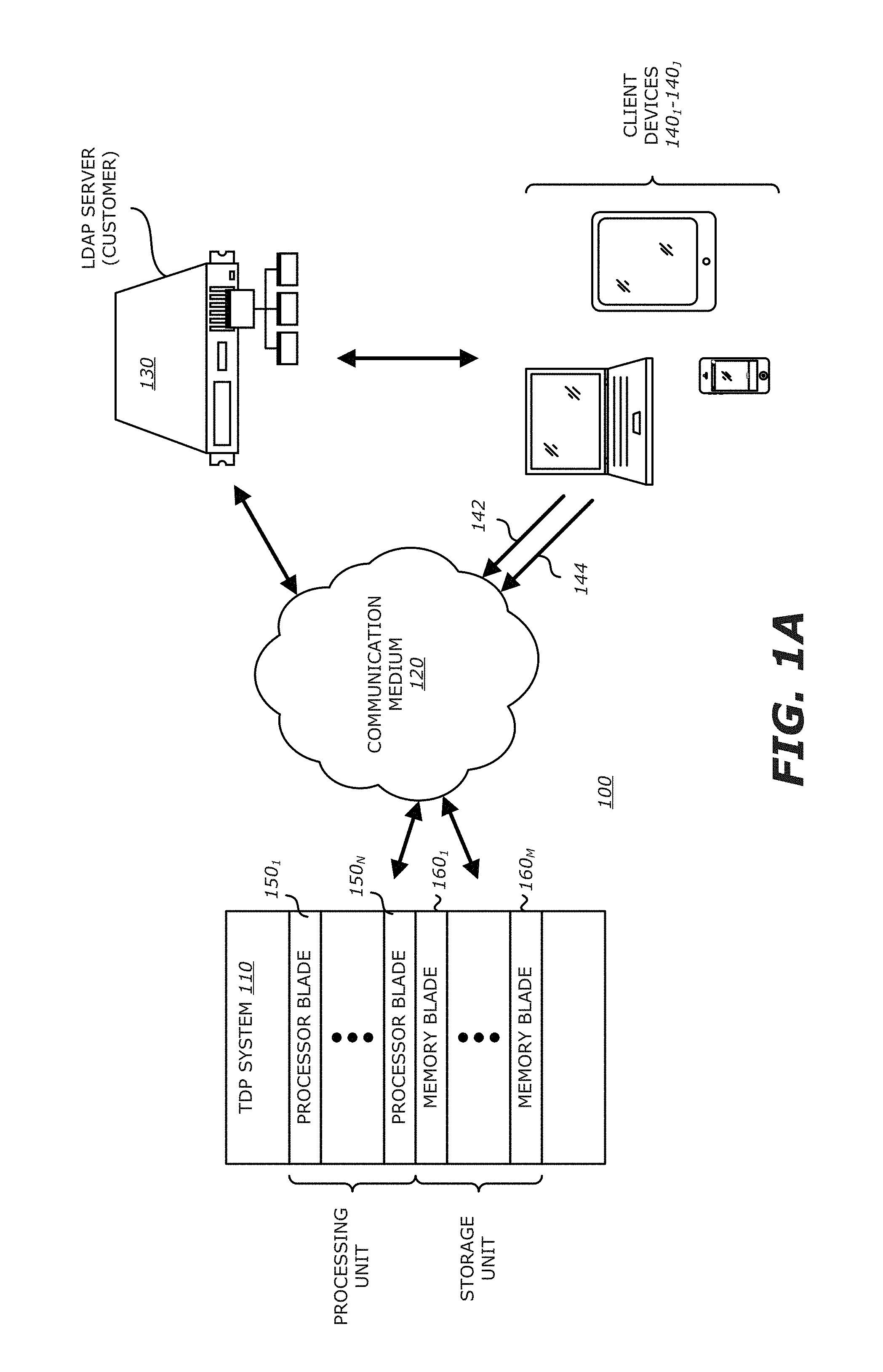
FIG. 1A is a block diagram of a first embodiment of an exemplary network adapted with a threat detection and prevention (TDP) system utilizing dynamic guest images for VM configuration.
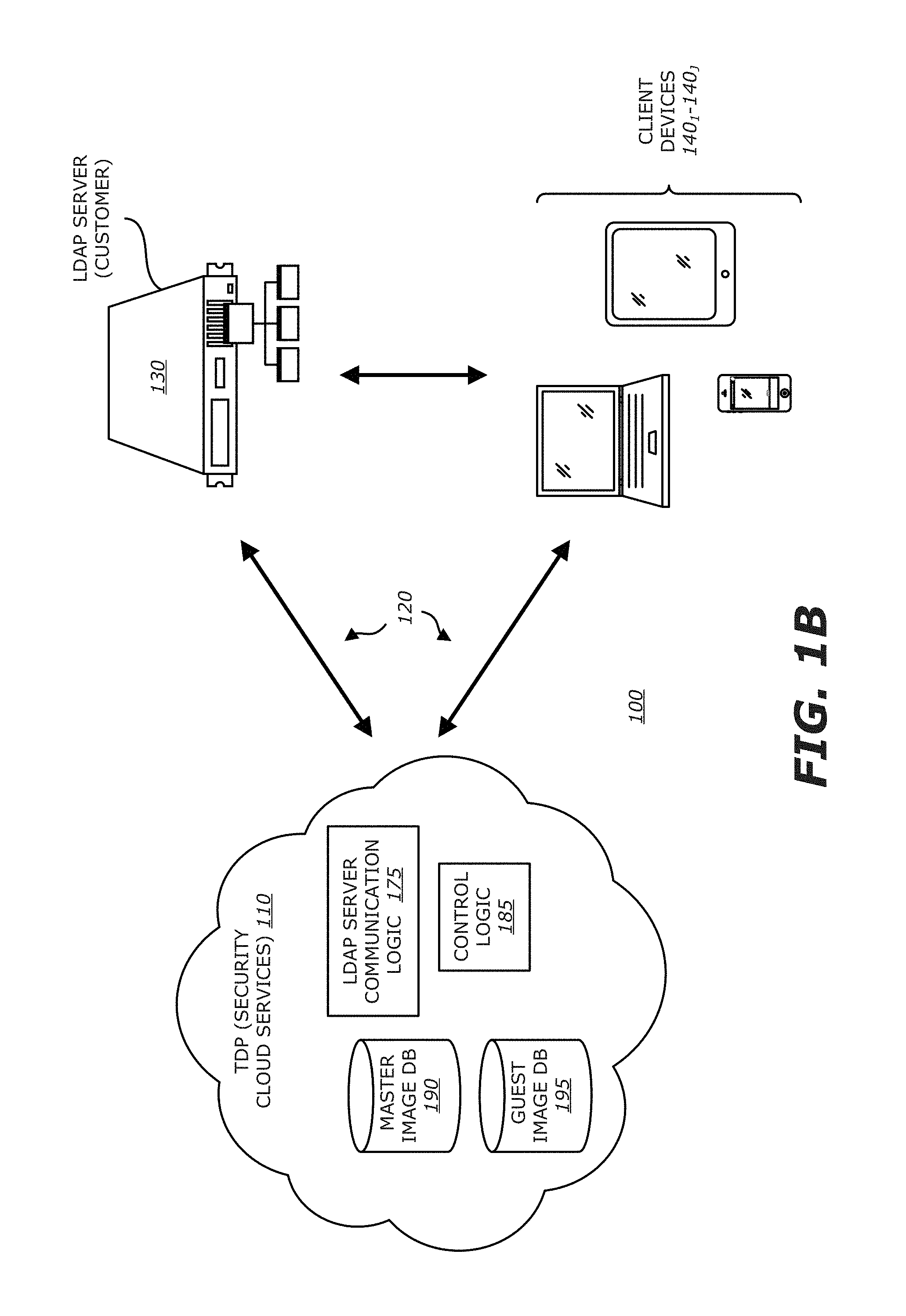
FIG. 1B is a block diagram of a second embodiment of an exemplary network adapted with a TDP system utilizing dynamic guest images for VM configuration.
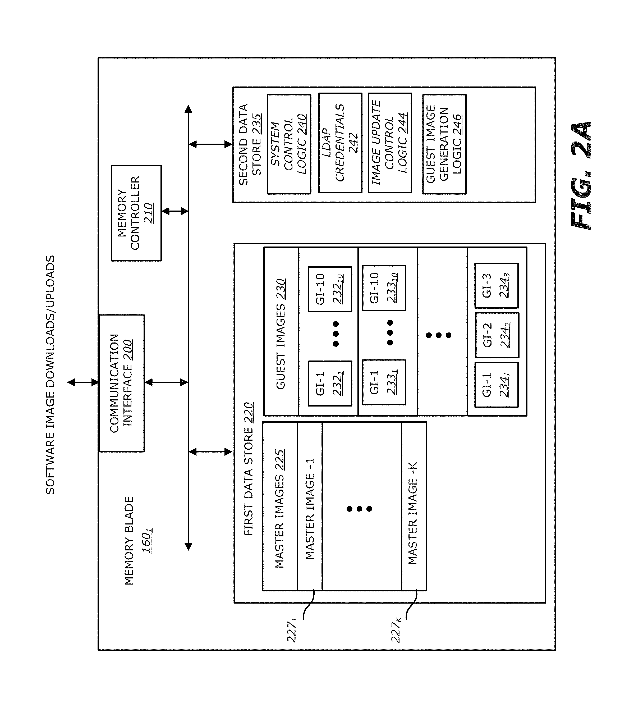
FIG. 2A is an exemplary embodiment of a logical representation of the memory blade being a component of the TDP system of FIG. 1A.
FIG. 2B is an exemplary embodiment of a logical representation of the processor blade being a component of the TDP system of FIG. 1A.
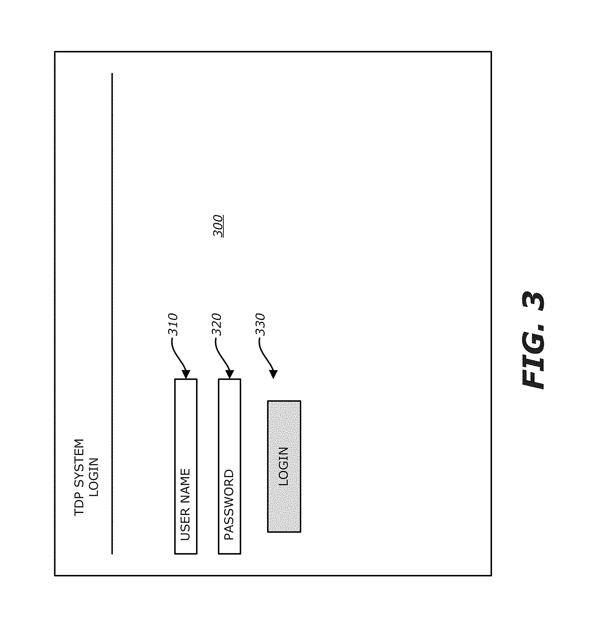
FIG. 3 is an exemplary embodiment of a first interactive display screen produced by the TDP system of FIG. 1A or 1B.
FIG. 4 is an exemplary embodiment of a second interactive display screen for operation selection produced by the TDP system of FIG. 1A or 1B.
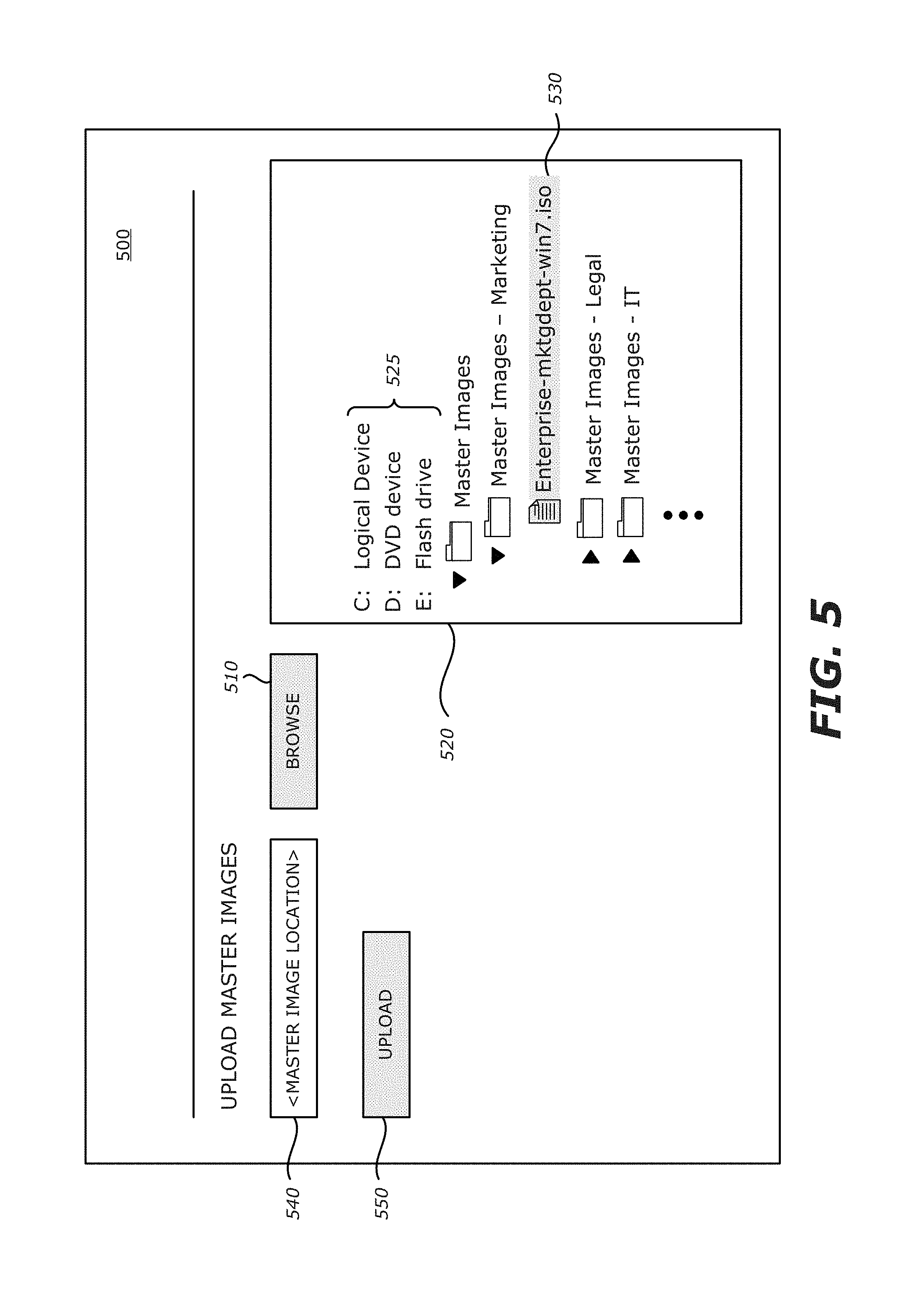
FIG. 5 is an exemplary embodiment of a third interactive display screen produced by the TDP system of FIG. 1A or 1B.
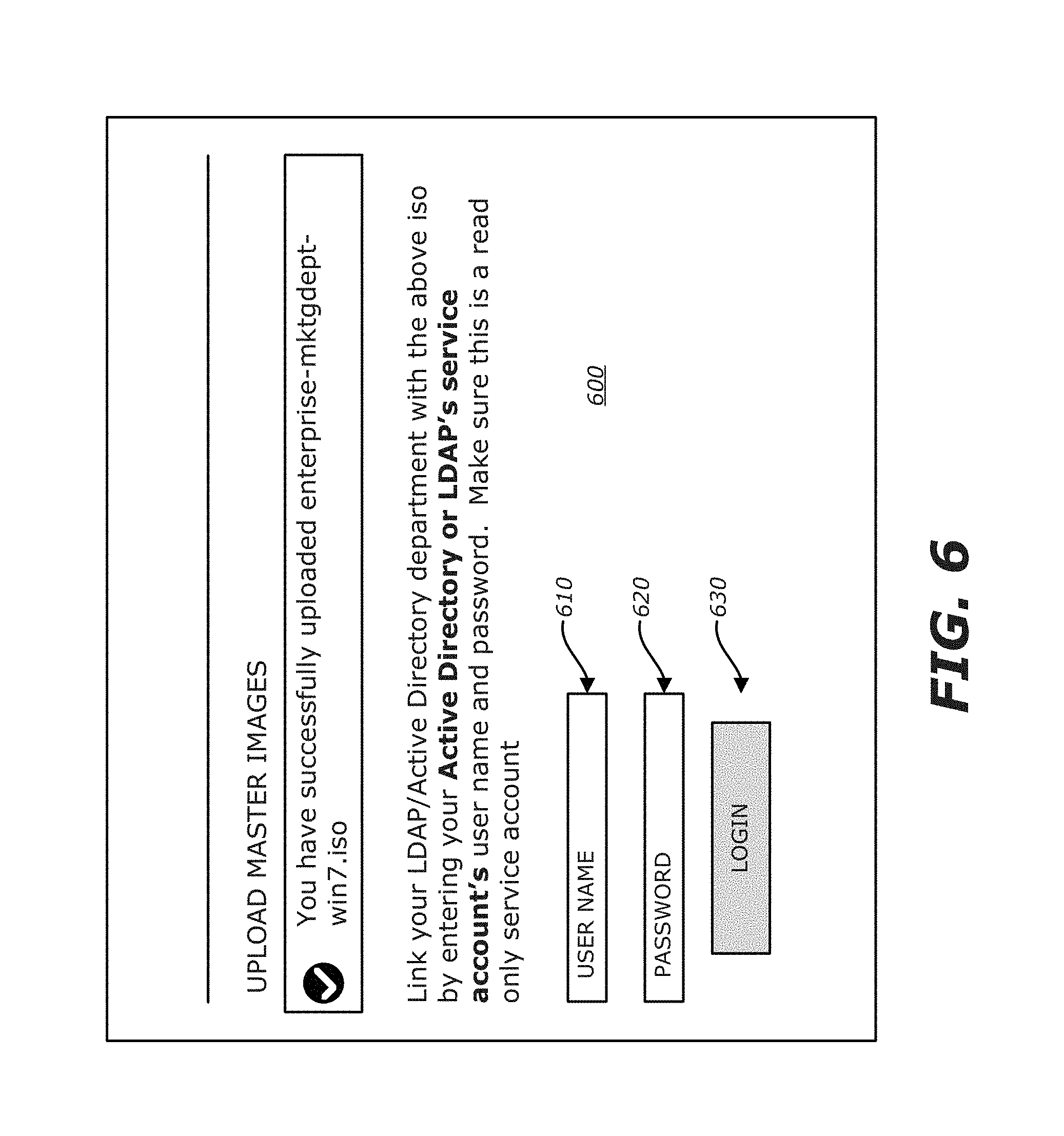
FIG. 6 is an exemplary embodiment of a fourth interactive display screen for relating an uploaded master image to one or more groups within an enterprise.
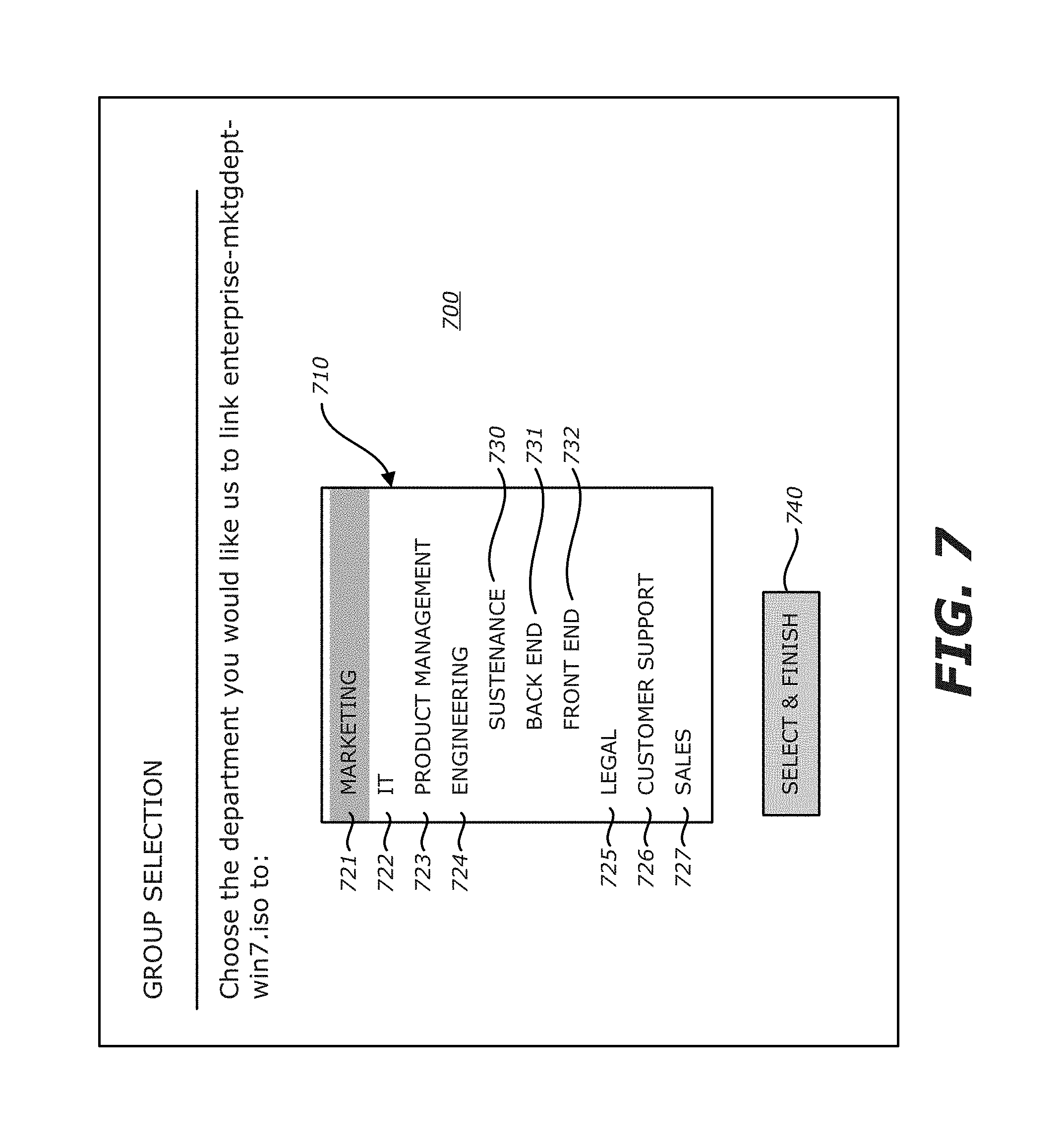
FIG. 7 is an exemplary embodiment of a fifth interactive display screen that produces a listing of the groups maintained by the LDAP server.
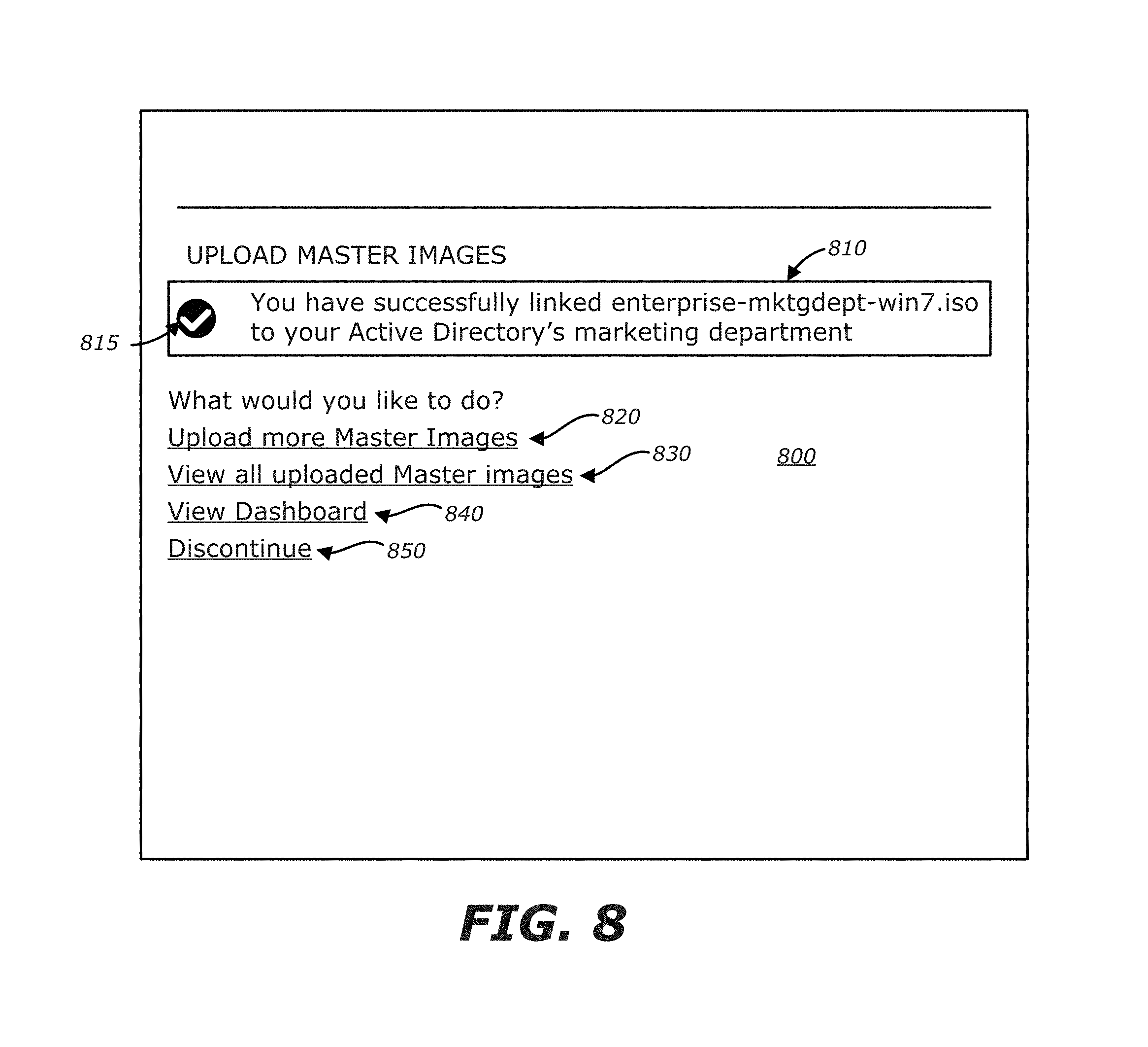
FIG. 8 is an exemplary embodiment of a fifth interactive display screen produced by the TDP system of FIG. 1A or 1B.
FIG. 9 is an exemplary embodiment of a sixth interactive display screen produced by the TDP system of FIG. 1A or 1B that operates as a dashboard.
FIG. 10 is an exemplary embodiment of a seventh interactive display screen produced by the TDP system 110 of FIG. 1A or 1B in response to selection of the second tab of the dashboard.
FIG. 11 is an exemplary embodiment of an interactive display screen for remediation.
FIG. 12 is an exemplary flowchart of a remediation scheme for transitioning a client device from an infected state to an uninfected state.
DETAILED DESCRIPTION
Various embodiments of the disclosure relate to a threat detection and prevention (TDP) system, in the form of a security appliance or security cloud services (generally referred to as a "security system"), which analyzes objects associated with monitored network traffic using one or more virtual machines (VMs) each dynamically configured with a guest image representing the actual (and current) operating state of a targeted client (electronic) device. Through VM configuration using guest images, the TDP system is able to perform a concentrated dynamic analysis on network traffic from/to a particular client device as well as to conduct real-time remediation of the particular client device upon infection.
Herein, each "guest image" is an image of the content and structure of the storage volume for a specific client device at a particular point in time, namely a "snapshot" of the stored information including software along with metadata associated on the operating system (OS) and Open Systems Interconnect (OSI) Application layer data supporting the software (e.g., address location, size information, registry keys set by software, etc.). Hence, each guest image represents the current operating state of the client device at the time that the guest image is generated and is specific to only that client device. A timestamp may be applied to each guest image, where the time at least provides information as to the chronological order of its guest image to other guest images (e.g., time, monotonic count value, etc.).
Initially, one or more master images may be uploaded into the TDP system by an end user or administrator of the network. A "master image" represents a base amount of content (e.g., software and corresponding metadata) that is loaded into client devices for use by a member (user) of a particular group. The groups may be segregated according to any desired rubric. For instance, each group may correspond to one or more departments and/or sub-departments within an enterprise. Alternatively, each group may correspond to different regions, different languages, or in fact, may correspond to different enterprises where the TDP system supports an entire conglomerate.
More specifically, according to one embodiment of the disclosure, the master image may represent the initial "storage volume" of a client device supplied to a member of a particular group or groups within the enterprise, namely the initial content to be stored in persistent storage (e.g., hard disk, flash memory, etc.) of the client device. According to another embodiment of the disclosure, the master image may represent the requisite software, perhaps differing among the groups, which is loaded into the client device having connectivity to an enterprise network.
After uploading the master images to the TDP system and relating each master image to its assigned group or groups, each group member (or client device) may be related to at least one master image based on information within a Lightweight Directory Access Protocol (LDAP) server. Initial and subsequent access to the LDAP server may be accomplished by the TDP system through supplied LDAP credentials. Of course, after initial uploading of the master image(s), it is contemplated that each master image may undergo a one-way hash operation to produce a (master) hash value that may be used, at least initially, to confirm that the client device has been configured properly.
Besides relating one or more master images with each client device (or member of an enterprise), guest images may be generated and stored in response to changes in the storage volume of the client device. For instance, in response to a triggering event, the client device may initiate a native Volume Back-up program (e.g., Volume Shadow Copy for Windows.RTM. OS; Time Machine for iOS.RTM., Google.RTM. Sync for Android.RTM. OS; iTunes.RTM. Sync for Mobile iOS.RTM., etc.) to upload changes in the operating state of the client device to the TDP system. These changes in operating state may be uploaded through an "image update message," such as an Application Programming Interface "API" call for example, which is prompted by a triggering event at the client device. One example of a "triggering event" includes a predetermined amount of change in storage volume at the client device (e.g., a change of persistent storage of 1 kilobyte "Kb", 10 Kb, 100 Kb, etc.). Another triggering event may include installation and/or deletion of a software application at the client device. Yet another triggering event may include completion of a download of data (e.g., a Portable Document Format "PDF" file, text document, an image, or a video clip) attached to an electronic mail (email) message at the client device.
When triggered by a change in storage volume due to installation of new software, the image update message (e.g., API call) may comprise the newly installed software along with metadata changes on the OS and OSI Application Layer which support the newly installed software (e.g., address location, size changes, registry keys changes to support the software application, etc.). Where the image update message is triggered by removal of software, the metadata changes may include changes to denote removal of the software as well as changes to the OS and OSI Application Layer in response to removal of the software.
It is contemplated that one or more previous guest images along with information within the image update message may be used to create, in real time, a current guest image for the user's client device. For remediation, multiple guest images (e.g., up to ten guest images) may be retained for each client device. As a result, in response to detecting an object suspected of being exploit and the object being activated (e.g., opened, run, etc.) by the "infected" client device, the TDP system may generate an alert to identify that the client device has transitioned from a non-infected state to an infected state. After generating the alert, an administrator or someone with high-level credentials (e.g., super user) may restore the client device to a non-infected state in accordance with the remediation policy for the customer. For instance, the most recent guest image prior to infection may be restored on the client device. Furthermore, the administrator may view the operations of the suspect (or suspicious) exploit in detail and/or may be able to reload non-malicious information lost by restoration of the most recent guest image.
Besides dynamic guest image creation along with triggered or automatic remediation in response to the electronic device becoming infected, the TDP system is adapted to conduct VM-based processing using these guest images to enhance accuracy in exploit detection. Also, an interface (dashboard) is provided that allows an administrator to have a complete visualization from a system level perspective (e.g., number of master & guest images stored, number of remediated/infected electronic devices) and from a user perspective (e.g., number of infections on electronic device operated by a particular user, types of software infected, etc.).
I. Terminology
In the following description, certain terminology is used to describe features of the invention. For example, in certain situations, both terms "logic" and "engine" are representative of hardware, firmware and/or software that is configured to perform one or more functions. As hardware, logic (or engine) may include circuitry having data processing or storage functionality. Examples of such circuitry may include, but is not limited or restricted to a microprocessor; one or more processor cores; a programmable gate array; a microcontroller; an application specific integrated circuit; receiver, transmitter and/or transceiver circuitry; semiconductor memory; or combinatorial logic.
Logic (or engine) may be in the form of one or more software modules, such as executable code in the form of an executable application, an application programming interface (API), a subroutine, a function, a procedure, an applet, a servlet, a routine, source code, object code, a shared library/dynamic load library, or one or more instructions. These software modules may be stored in any type of a suitable non-transitory storage medium, or transitory storage medium (e.g., electrical, optical, acoustical or other form of propagated signals such as carrier waves, infrared signals, or digital signals). Examples of a "non-transitory storage medium" may include, but are not limited or restricted to a programmable circuit; a semiconductor memory; non-persistent storage such as volatile memory (e.g., any type of random access memory "RAM"); persistent storage such as non-volatile memory (e.g., read-only memory "ROM", power-backed RAM, flash memory, phase-change memory, etc.), a solid-state drive, hard disk drive, an optical disc drive, or a portable memory device. As firmware, the executable code is stored in persistent storage.
The term "object" generally refers to a collection of data, such as a group of related packets, normally having a logical structure or organization that enables classification for purposes of analysis. For instance, an object may be a self-contained element, where different types of such objects may include an executable file, non-executable file (such as a document or a dynamically link library), a Portable Document Format (PDF) file, a JavaScript.TM. file, Zip.TM. file, a Flash file, a document (for example, a Microsoft Office.RTM. document), an email, downloaded web page, an instant messaging element in accordance with Session Initiation Protocol (SIP) or another messaging protocol, or the like.
The term "flow" generally refers to a collection of related objects, communicated during a single communication session (e.g., Transport Control Protocol "TCP" session), perhaps between a source device and a destination device. A client device may be one of the source or destination devices.
A "message" generally refers to information transmitted as information in a prescribed format, where each message may be in the form of one or more packets or frames, an HTTP-based transmission, or any other series of bits having the prescribed format.
The term "transmission medium" is a physical or logical communication path with a client device, which is an electronic device with data processing and/or network connectivity such as, for example, a stationary or portable computer including a desktop computer, laptop, electronic reader, netbook or tablet; a smart phone; or wearable technology. For instance, the communication path may include wired and/or wireless segments. Examples of wired and/or wireless segments include electrical wiring, optical fiber, cable, bus trace, or a wireless channel using infrared, radio frequency (RF), or any other wired/wireless signaling mechanism.
In certain instances, the term "verified" are used herein to represent that there is a prescribed level of confidence (or probability) on the presence of an exploit within an object under analysis. Also, an "exploit" may be construed as information (e.g., executable code, data, command(s), etc.) that attempts to take advantage of a software vulnerability, namely a coding error or artifact of software (e.g., computer program) that allows an attacker to alter legitimate control flow during processing of the software (computer program) by an electronic device, and thus, causes the electronic device to experience undesirable or unexpected behaviors.
The term "computerized" generally represents that any corresponding operations are conducted by hardware in combination with software and/or firmware.
Lastly, the terms "or" and "and/or" as used herein are to be interpreted as inclusive or meaning any one or any combination. Therefore, "A, B or C" or "A, B and/or C" mean "any of the following: A; B; C; A and B; A and C; B and C; A, B and C." An exception to this definition will occur only when a combination of elements, functions, steps or acts are in some way inherently mutually exclusive.
As this invention is susceptible to embodiments of many different forms, it is intended that the present disclosure is to be considered as an example of the principles of the invention and not intended to limit the invention to the specific embodiments shown and described.
II. General Architectures
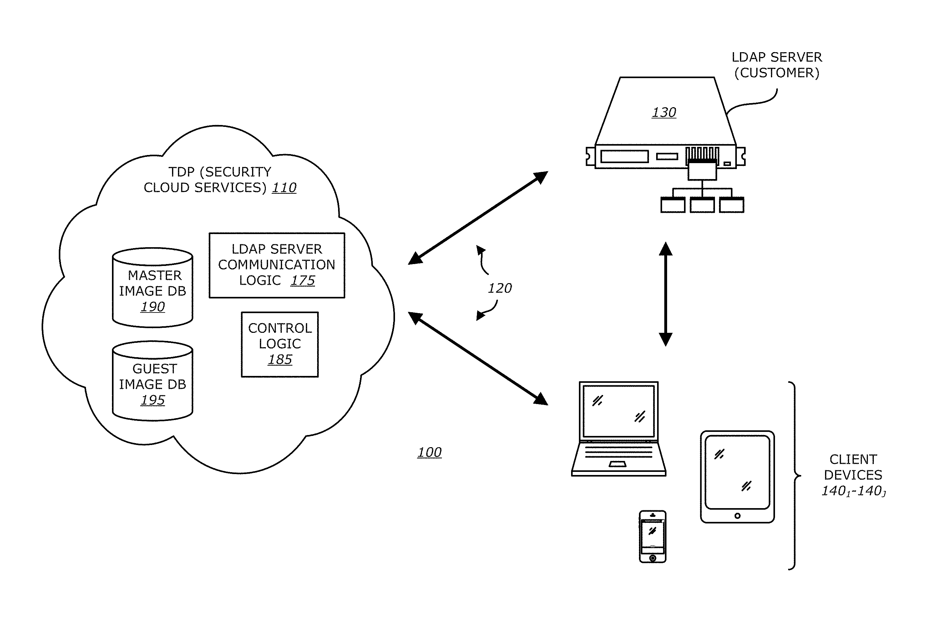
Referring to FIG. 1A, a block diagram of a first embodiment of a client-based exploit detection scheme controlled by a threat detection and prevention (TDP) system utilizing dynamic guest images for VM configuration is shown. Herein, network 100 comprises a TDP system 110 that is configured to monitor network traffic propagating over a communication medium 120 being part of the network 100. The TDP system 110 is communicatively coupled to a Lightweight Directory Access Protocol (LDAP) server 130 and one or more client devices 140.sub.1-140.sub.J (J.gtoreq.1).
As shown in FIG. 1A, TDP system 110 comprises one or more processor blades 150.sub.1-150.sub.N (N.gtoreq.1) which may be organized in a vertical, centralized (rack) deployment as shown. The processor blades 150.sub.1-150.sub.N feature logic that is responsible for performing static and/or dynamic exploit analysis on objects extracted from network traffic propagating over the communication medium 120. For instance, as an illustrative embodiment, each processor blade 150.sub.i (1.ltoreq.i.ltoreq.N) may operate as a stand-alone processing unit that is individually responsible for performing static and/or dynamic exploit analysis on objects extracted from network traffic associated with a particular set of client devices (e.g., client devices for a particular department, particular region, etc.). Alternatively, two or more (and perhaps all) processor blades 150.sub.1-150.sub.N may operate in a collective manner. For instance, a first processor blade 150.sub.1 may operate as a master processing unit while processor blade 150.sub.2 may operate as a slave processing unit or these processor blades 150.sub.1-150.sub.N may operate collectively in accordance with a selected load sharing scheme.
Additionally, the TDP system 110 includes one or more memory blades 160.sub.1-160.sub.M (M.gtoreq.1). The memory blades 160.sub.1-160.sub.M comprise logic that is individually or collectively responsible for controlling TDP system configuration, which may include (1) uploading and/or storing master images, (2) generating and/or storing guest images for each client device 140.sub.1, . . . , or 140.sub.J, and/or (3) generating a dashboard or other display screens for configuration and control of the TDP system. For instance, each memory blade 160.sub.i (1.ltoreq.i.ltoreq.M) may operate as a stand-alone storage unit that is individually responsible for maintaining master and guest images for particular group(s) of an enterprise (or different enterprises). Alternatively, two or more (and perhaps all) memory blades 160.sub.1-160.sub.M may operate in a collective manner. For instance, a first memory blade 160.sub.1 may operate to store master images while the other memory blades 160.sub.2-160.sub.M may operate to store guest images for different groups within the enterprise (or different guest images for different enterprises). Of course, the particular configurations for memory blades 160.sub.1-160.sub.M as well as processor blades 150.sub.1-150.sub.N may be adjusted according to customer needs.
At initial set-up, the LDAP credentials for accessing a customer's LDAP server may be obtained by (and optionally stored in) at least one of the memory blades 160.sub.1-160.sub.M. The accessed LDAP credentials enable the memory blades 160.sub.1-160.sub.M to subsequently and automatically access content within the LDAP server 130 in order to identify group membership associated with each client device (user). The group membership signifies the particular master image assigned to the group member for configuration of his/her client device, where the master image provides an initial operating state (e.g., base software configuration). Thereafter, in response to storage volume changes made on the client device, one or more memory blades 160.sub.1-160.sub.M generate guest images for use in VM configuration. The guest images may be stored locally within the memory blades 160.sub.1-160.sub.M or externally, and the number of guest images stored per client device may be limited to a certain prescribed number set by an administrator.
More specifically, in response to a first storage volume change greater than a predetermined amount, the client device 140.sub.1 outputs an image update message 142 to the TDP system 110. The image update message 142 causes the TDP system 110 to generate a first guest image. The first guest image is based on a particular master image assigned to the group member having control of client device 140.sub.1 along with additional data that caused the storage volume change to occur. Similarly, a second guest image is based on the first guest image along with information contained within a subsequent image update message 144 produced by client devices 140.sub.1, where the information includes the additional data from the first storage volume change to the second storage volume change. This reiterative process continues until "X" guest images are stored for a particular user (e.g., X.gtoreq.10 guest images). Once the image buffer is written with "X" guest images, any subsequent guest images may overwrite the older guest images in accordance with a first-in, first out (FIFO) storage scheme.
As an illustrative example, one or more master images may be uploaded by an administrator of the network 100 into the TDP system 110. These master images may be fetched from persistent storage accessible to the administrator (e.g., administrator's computer, dedicated server, disc, flash drive, etc.). For illustrative purposes, the master images correspond to base software configurations on a department and/or sub-department basis, where a master image for members of a first department (or sub-department) may differ from the master image for members of a second department (or sub-department). For security reasons, a master image may undergo static and dynamic analysis by one of the processor blades 150.sub.1-150.sub.N before that master image is uploaded to any of the memory blades 160.sub.1-160.sub.M.
After uploading of the master images to one or more of the memory blades 160.sub.1-160.sub.M and relating the master images to the particular groups, the particular users (and their corresponding client devices) may be related to the groups through information stored within the LDAP server 130. More specifically, logic within the memory blades 160.sub.1-160.sub.M may be adapted to create one or more tables that provide correspondence between (1) client devices (identified by an identifier such as assigned computer name, MAC address, etc.); (2) assigned user for each client device; (3) group (e.g., department or sub-departments, etc.) to which the user belong; (4) addressing information associated with the master image corresponding to the group; and/or (5) addressing information for guest images associated with each particular user.
It is contemplated that multiple guest images may be generated and stored for each client device in response to changes in the storage volume of that client device. For example, in response to a predetermined amount of change in storage volume, the client device initiates a native Sync program (e.g., Volume Shadow Copy for Windows.RTM. OS; Time Machine for iOS.RTM., Google.RTM. Sync for Android.RTM. OS; iTunes.RTM. Sync for Mobile iOS.RTM., etc.) to commence transmission of an image upload message (e.g., messages 142, 144, etc.) that includes changes in the operating state of the client device (e.g., newly installed software application, metadata changes on the OS and OSI Application Layer that support the installed application, etc.). These operating state changes along with the image of a prior operating state (e.g., master image, preceding guest image, etc.) are used to generate a current guest image for the client device.
Prior to conducting VM-based exploit analysis on one or more objects extracted from network traffic from/to a particular client device 140.sub.1, . . . , or 140.sub.J (e.g., client device 140.sub.1), one or more processor blades 150.sub.1-150.sub.N (e.g., processor blade 150.sub.1) are configured to access at least a current guest image for client device 140.sub.1 from memory blade 160.sub.1-160.sub.M (e.g., memory blade 160.sub.M), where the current guest image is used for configuring one or more virtual machines operating within processor blade 150.sub.1. Of course, it is contemplated that other guest images, such as older guest or images for client devices other than client device 140.sub.1 (e.g., client devices associated with users belonging to the same department), may be tested to confirm that any detected exploits are isolated to newly added content or content exclusively contained within that particular client device.
Referring now to FIG. 1B, a block diagram of a second embodiment of a client-based exploit detection scheme controlled by the TDP system utilizing dynamic guest images for VM configuration is shown. Herein, deployed as part of a private network or part of a publicly accessible network, TDP system 110 operates as security cloud services configured to monitor network traffic propagating over the communication medium 120 that partially forms the network 100. Similar to the connectivity described in FIG. 1A, the TDP system 110 is communicatively coupled to LDAP server 130 and one or more client devices 140.sub.1-140.sub.J.
As shown in FIG. 1B, the security cloud services forming TDP system 110 comprises one or more databases to maintain master images of an enterprise as well as multiple guest images for each client device 140.sub.1-140.sub.J and control logic to maintain these databases. At initial set-up, being part of the security cloud services, the LDAP server communication logic 175 may be configured to obtain LDAP credentials in order to gain access a customer's LDAP server 130. The information accessed from the LDAP server 130 may be used to map (i) identifiers of the client devices 140.sub.1-140.sub.J to particular users assigned to these client devices, and (ii) the particular users to corresponding groups (e.g., departments or sub-departments). From this information and prior identification as to which groups corresponding to which master images, control logic 185 within the security cloud services is able to determine which master image is the base image for which user. The master images may be stored in master image database 190.
Thereafter, in response to volume changes made on the client device 140.sub.1, control logic 185 generates guest images based originally from the master image associated with that client device 140.sub.1. For instance, a first guest image for client device 140.sub.1 may be based on (i) a particular master image assigned to the user of client device 140.sub.1 and (ii) the differential information associated with the storage volume change. As an example, the differential information may include a newly installed software application and metadata (OS and OSI Application layer) to support the software application. The guest images are stored in guest image database 195.
The generation of second and subsequent guest images may be performed in a reiterative manner until "X" guest images are stored for each particular user. Once the "X" guest images are stored, any subsequent guest images may overwrite the oldest guest image in accordance with a first-in, first out (FIFO) storage scheme for example.
Referring to both FIGS. 1A-1B, it is contemplated that a hash value may be generated and stored for each master image for subsequent confirmation that the base software configuration for a particular client device (controlled a particular user) is accurately assigned. This may be accomplished by conducting a hash operation on the initial configuration and comparing the resultant hash value to the hash value for the master image assigned to the client device. Additional hash values may be generated for each change in storage volume where a series of hash values may be used to confirm upload accuracy.
Referring to FIG. 2A, an exemplary embodiment of a logical representation of the memory blade 160.sub.1 of FIG. 1A is shown. Herein, the memory blade 160.sub.1 comprises a communication interface 200, a memory controller 210, a first data store 220 and a second data store 235. The communication interface 200 provides connectivity with resources within network 100, including LDAP server 130 and one or more client devices 140.sub.1-140.sub.J illustrated in FIG. 1A. Furthermore, the communication interface 200 provides connectivity with one or more processor blades 150.sub.1-150.sub.N and/or one or more of the remaining memory blades 160.sub.2-160.sub.M of FIG. 1A. Hence, the blade server implementation for the TDP system 110 provides scalability through increased software image storage capacity through increased memory blades and/or increased processing capability through increased processor blades.
Memory controller 210 is configured to control the initial configuration of the memory blade based on initial upload of one or more master images 225, relate the master image(s) to client devices adapted to access the network, and generate guest images 230 for changes in operating state at the client devices.
More specifically, in response to a login request by an administrator, the memory controller 210 executes system control logic 240 that produces one or more interactive display screens to enable the administrator to upload and relate master images 227.sub.1-227.sub.K to particular groups as well as download a dashboard to view system status and control remediation, as described below.
Where the administrator selects to upload one or more master images, the memory controller 210 controls storage of master images 227.sub.1-227.sub.K within the first data store 220. The memory controller 210 may further store addressing information of each master image 227.sub.1-227.sub.K within internal memory (not shown) or within one of the data stores 220 and 235.
After completing an upload of the master image(s), the memory controller 210 may control relating the master image(s) to one or more ("J") client devices based on information acquired from the LDAP server. In particular, the memory controller 210, under control by the system control logic 240, generates one or more interactive display screens into which LDAP credentials 242 for accessing a customer's LDAP server may be conveyed. The LDAP credentials 242 may be optionally cached (as shown) to enable the TDP system to automatically access the LDAP server in response to subsequent master image uploads or to periodically check if any users have moved departments (where the software configuration should be changed) or have left the enterprise (where guest images can be deleted or downloaded to external storage for retention). Contents within the LDAP server enable the master image to be related to particular client devices that should be loaded with the software configuration represented by the master image.
As further shown in FIG. 2A, the first data store 220 of memory blade 160.sub.1 may be configured to store guest images for each of the client devices 140.sub.1-140.sub.J. For instance, as an illustrative example, a maximum of ten guest images 232.sub.1-232.sub.10 are stored for a first client device 140.sub.1, ten guest images 233.sub.1-233.sub.10 are stored for a second client device 140.sub.2, and three guest images 234.sub.1-234.sub.3 are currently stored for an L.sup.th client device 140.sub.L.
In response to receiving a native Sync program signal and subsequent image update message, under control by the image update control logic 244, the memory controller 210 may locate the most recent guest image associated with the client device that initiated the image update message through timestamp review and extract update information associated with the storage volume changes from the update image message. The most recent guest image and the extracted update information are provided to the guest image generation logic 246. Processed by the memory controller 210, the guest image generation logic 246 creates a current guest image representing the current operating state of the client device based on the most recent guest image and the update information. The current guest image along with its timestamp may be stored in an address range reserved for guest images for the particular client device.
Referring now to FIG. 2B, an exemplary embodiment of a logical representation of the processor blade 150.sub.1 is shown. Herein, the processor blade 150.sub.1 comprises a communication interface 250, a static analysis engine 255, a schedule 260, a dynamic analysis engine 270, a classification engine 285 and reporting logic 290. The communication interface 250 provides connectivity with resources within network 100 of FIG. 1A, including one or more client devices to which alerts may be generated. Furthermore, communication interface 250 provides connectivity with (i) one or more memory blades 160.sub.1-160.sub.M from which guest images for configuring one of more virtual machines within the dynamic analysis engine 270 may be obtained and/or (ii) one or more of the remaining processor blades 150.sub.2-150.sub.N.
Herein, according to this embodiment of the disclosure, processor blade 150.sub.1 is an electronic device deployed within the TDP system 110 (see FIG. 1A) that is adapted to (i) intercept network traffic that is routed over a communication network to/from a particular client device (not shown) and (ii) monitor, in real-time, content within the network traffic. Although not shown, the processor blade 150.sub.1 is communicatively coupled to a management system that may be configured to automatically update one or more exploit signatures and/or vulnerability signatures used by logic within static analysis engine 255. Stored in signature database 256, each of these signatures may represent a prior detected exploit or an uncovered software vulnerability. Such sharing may be conducted automatically or through manual uploads. Also, such sharing may be conducted freely by the TDP system 110 with other TDP systems or subject to a subscription basis.
Herein, according to the embodiment illustrated in FIG. 2B, the static analysis engine 255 may include one or more software modules that, when executed by one or more processors, performs static scanning on a particular object. Examples of different types of static scanning may include exploit signature checks and/or vulnerability signature checks. Signature check operations may involve accessing pre-stored signatures from one or more non-transitory storage mediums such as signature database 256.
In general, referring to FIG. 2B, the static analysis engine 255 is communicatively coupled to receive one or more objects from network traffic which may be related or unrelated to each other. For instance, one object may be a series of HTTP packets operating as a flow routed over the network. The static analysis engine 255 comprises exploit matching logic 257 that performs exploit signature checks, which may involve a comparison of one or more pre-stored exploit signatures (pre-configured and predetermined attack patterns against the suspect object) from signature database 256. Similarly, the signature matching logic 258 performs vulnerability signature checks, which may involve a process of uncovering deviations in messaging practices set forth in applicable communication protocols (e.g., HTTP, TCP, etc.). As an illustrative example, HTTP messages may be analyzed to determine compliance with certain message formats established for the protocol (e.g., out-of-order commands). Furthermore, payload parameters of the HTTP messages may be analyzed to determine further compliance.
Upon detecting a match during the exploit signature check and/or the vulnerability signature check (an object under analysis has characteristics that suggest the object is an exploit), the static analysis engine 255 determines that the object is "suspicious," namely has characteristics that suggest the object is an exploit, and routes the suspect object to the dynamic analysis engine 270 for more in-depth analysis. In one embodiments, the static analysis may alternatively or additionally include applying heuristics to identify suspicious characteristics of the object such as communication protocol anomalies for example in a flow.
The dynamic analysis engine 270 is configured to provide more in-depth analysis of suspect object(s) from the static analysis engine 255 by analyzing behaviors during processing of the suspect object(s) in order to verify whether or not the suspect object is an exploit.
More specifically, after static scanning has been completed, the static analysis logic 255 provides the suspect object to the dynamic analysis engine 270 for in-depth dynamic analysis using virtual machines (VMs) 276.sub.1-276.sub.R (R.gtoreq.1). For instance, the dynamic analysis engine 270 may simulate transmission to and receipt by a destination device comprising the virtual machine. Of course, if the object is not suspected of being an exploit, the static analysis engine 255 may simply discard the results or store them with an external data source.
According to one embodiment, one or more VMs 276.sub.1-276.sub.R within the virtual execution environment 275 may be configured based on metadata extracted from the network traffic (e.g., address information to identify the client device operating as the source or destination of the network traffic). In particular, one or more guest images for the identified client device are selected by VM provisioning logic 265 within the scheduler 260 and provided to the VM execution environment 275, where VM 276.sub.1 may be configured with the most recent guest image of the client device. This provisioning of guest images for the identified client device provides a more accurate VM configuration for analyzing the suspect object than conventional means.
According to one embodiment of the disclosure, the dynamic analysis engine 270 is adapted to execute one or more VMs 276.sub.1-276.sub.R to simulate the receipt and execution of content associated with the suspect object within a run-time environment as expected for the suspect object. For instance, the dynamic analysis engine 270 may include processing logic 272 that "replays" the network communication in a virtual machine (e.g., VM 276.sub.1) in accordance with (e.g., in a sequence prescribed by) the applicable communication protocol by sending its data packets to VM 276.sub.1, and synchronizes any return network traffic generated from the VM 276.sub.1 in response to the network communication. The processing logic 272 may suppress (e.g., discard) the return network traffic such that it is not transmitted to any host or other real ("live") device but is nonetheless intercepted for analysis. The processing logic 272 may change destination IP addresses of data packets in the network communication to one or more IP addresses assigned to the VM 276.sub.1 or may alter a time scale to assist in detonation of time bomb exploits.
Herein, the static analysis engine 255 and the dynamic analysis engine 270 may be one or more software modules executed by the same processor or different processors, where these different processors may be located within the same processor package (e.g., different processor cores) and/or located at remote or even geographically remote locations that are communicatively coupled (e.g., by a dedicated communication link) or a network.
As further shown in FIG. 2B, the monitoring logic 278 within the dynamic analysis engine 270 may be configured to monitor behavior of the suspect object being analyzed by one or more VMs 276.sub.1, . . . , and/or 276.sub.R, for detecting anomalous or unexpected activity indicative of an exploit. If so, the suspect object may be determined as being associated with malicious activity, and thereafter, monitoring logic 278, perhaps operating with a score determination logic (not shown), may route the VM-based results 280 (e.g., computed score, information associated with the detected anomalous behaviors, and other information associated with the detected malicious activity by the suspect object) to classification engine 285.
According to one embodiment of the disclosure, the classification engine 285 comprises prioritization logic 287 and score determination logic 289. The prioritization logic 287 may be configured to apply weighting to the VM-based results 280 provided from dynamic analysis engine 270 and/or results from the static analysis engine 255 (represented by a dashed input). These results may include a score produced by score determination logic implemented within dynamic analysis engine 270 and/or static analysis engine 255, where the "score" is a value that classifies the threat level of the detected potential exploit.
Herein, the score determination logic 289 comprises one or more software modules that are used to determine a probability (or level of confidence) that the suspect object is an exploit. Based on the VM-based result 280 and/or results from the static analysis engine 255, score determination logic 289 may be configured to generate a value (referred to as an "overall score") that classifies the object or a series of objects as an exploit. It is contemplated that the score may be assigned to the suspect object as a whole by mathematically combining scores determined by analysis of different content associated with the same suspect object to obtain an overall score for that suspect object.
If the score determination logic 289 generates an overall score that represents the suspect object has been verified to be an exploit, information may be provided to alert/report generation logic 295 within the reporting logic 290 to notify a network administrator of the exploit detected and such information may be stored within one of the memory blades 160.sub.1-160.sub.M for extraction and display within a dashboard as described below.
III. Exemplary Dynamic Guest Image Creation
Referring to FIG. 3, an exemplary embodiment of a first interactive (Login) display screen 300 produced by TDP system 110 of FIG. 1A or 1B is shown. Herein, in order to gain access to the TDP system 110 for loading of one or more master images that are used in the generation of guest images for VM configuration, an administrator initially establishes a network connection with the TDP system. This network connection may be established in accordance Hypertext Transfer Protocol (HTTP) Request or HTTP Secure (HTTPS) communication protocols.
As shown, an initial request for access to the TDP system is redirected to provide a Login display screen 300 that features at least two entry fields; namely a User Name 310 and a Password 320. The User Name entry field 310 requires the user to enter a registered user name in order to identify the user seeking access to the TDP system. Password entry field 320 allows the user to enter his or her password.
Once a login button 330 is selected, the user name and password are provided to logic within the TDP system, such as the system control logic 240 of FIG. 2A. Once the user seeking access to the TDP system has been authenticated, access privileges for that user are set and the user is provided with a second interactive display screen 400 as shown in FIG. 4.
Referring now to FIG. 4, an exemplary embodiment of the second interactive display screen 400 for operation selection is shown. Herein, interactive display screen 400 comprises a plurality of select area 410 and 420 that, when selected, signal the TDP system as to which operations are requested. As shown, the select areas 410 and 420 comprise (1) a link 410 to commence uploads of one or more master images and (2) a link 420 to download a dashboard (area 420).
For instance, upon first area 410 being selected, the TDP system produces a third interactive display screen, namely master image upload display 500 as shown in FIG. 5. Master image upload display 500 includes a "Browse" button 510 that, when selected, causes a pull-down listing 520 to be displayed. The pull-down listing 520 comprises a plurality of storage locations 525 from which a particular master image 530 may be retrieved for uploading to the TDP system. These storage locations 525 may include local storage at the network administrator's computer (e.g., hard disk drive, optical drive, etc.), external storage at a remote file share, or the like. Hence, upon selection of the particular master image that is sequentially displayed in search area 540 and activation of the "Upload" button 550, the particular master image is uploaded to one of the memory blades 160.sub.1-160.sub.M (FIG. 1A) or master guest database 190 (FIG. 1B).
In lieu of uploading single master images to the TDP system, master image upload display 500 provides a capability of batch uploads. According to one embodiment of the disclosure, a folder 560 from the pull-down listing 520 may be selected where, upon being displayed in search area 540 and activation of the "Upload" button 550 occurs, all master images within the selected folder are uploaded. Alternatively, the master images may be uploaded using a command string. For instance, a File Transfer Protocol (FTP) command string (e.g., "sftp -b batchfile . . . ", where batchfile has a list of "Put" commands for master images along with their storage locations) is entered into search area 540 and upon activation of the "Upload" button 550, all master images identified in the list (batchfile) are subsequently uploaded by the TDP system.
Referring now to FIG. 6, an exemplary embodiment of a fourth interactive display screen 600 produced by the TDP system 110 of FIG. 1A or 1B for relating an uploaded master image to one or more groups within an enterprise is shown. Herein, display screen 600 comprises a plurality of entry fields area 610 and 620 in order to relate content within the LDAP server for the enterprise network with the uploaded master images. A first entry field 610 requires entry of a LDAP credential such as a user name for accessing the LDAP server. A second entry field 620 requires entry of a password to gain access to content within the LDAP server, which is a database including groups and members (or client devices) being part of the corresponding group.
Once a login button 630 is selected and the entered LDAP credential has been authenticated, a fifth interactive display screen 700 is provided that produces a listing of the groups maintained by the LDAP server, as shown in FIG. 7. Herein, a listing 710 of the groups comprises different departments and sub-departments of an enterprise. For instance, the departments may include Marketing 721, IT 722, Product Management 723, Engineering 724, Legal 725, Customer Support 726 and Sales 727. The sub-departments for the Engineering department 724, such as Sustenance 730, Back-End 731 and Front-End 732, may be selected to provide greater group granularity so that client devices controlled by members in different sections within the department may be configured differently.
As an illustrative example, members of the Engineering department 724 within an enterprise may be associated with a different master image (e.g., different software and/or versions of software) than member of the Marketing department 721. Similarly, members within the Back-End section 731 of the Engineering department 724 may be associated with a different master image (e.g., different software and/or versions of software) than member of the Front-End section 732 of the Engineering department 724.
One or more of these departments and/or sub-departments may be selected, and upon selection of the "Select & Finish" button 740, the TDP system relates the particular master image to the selected department(s) and/or sub-department(s). As an illustrative embodiment, the Marketing department 721 has been selected for relating a master image thereto.
Referring now to FIG. 8, an exemplary embodiment of a fifth interactive display screen 800 produced by the TDP system 110 of FIG. 1A or 1B is shown. In response to successfully relating (linking) the master image (enterprise-mktgdept-win7.iso) to the LDAP's Marketing department as illustrated in FIGS. 5-7, a message 810 indicating the successful relation of the master image to a particular LDAP group is generated along with an image 815 identifying the successful relation. Thereafter, for every prescribed change in storage volume at every registered client device associated with a user of the Marketing department, the TDP system produces a new guest image associated with that client device.
According to one embodiment of the disclosure, where guest images are generated in accordance with a "push" update scheme, the client device is loaded with a native Sync program that periodically, aperiodically, or continuously monitors for changes in storage volume at the client device. In response to a difference in volume exceeding a prescribed amount, the client device issues an image update message with information associated with the differences in operating state based on the storage volume changes. According to another embodiment of the disclosure, where guest images are generated in accordance with a "pull" update scheme, the TDP system may be configured to periodically or aperiodically poll the client devices to inquire whether such devices have experienced a storage volume change that exceeds the prescribed amount since the last polling event. If so, the client device issues an image update message with information associated with the differences in operating state based on the storage volume changes. These differences are used to create a current guest image associated with the client device that is used for exploit detection as described above.
Referring back to FIG. 8, the fifth interactive display screen 800 comprises a first display element 820 that, when selected, returns to the third interactive screen display 500 to continue uploading of additional master images. Screen display 800 further comprises display elements that, when selected, cause the TDP system to (i) display all uploaded master images (display element 830), (ii) view the dashboard (display element 840; FIG. 9) or (iii) disconnect communications with the TDP system (display element 850).
IV. Exemplary Dashboard Graphic User Interface
Referring to FIG. 9, an exemplary embodiment of a sixth interactive display screen 900 produced by the TDP system 110 of FIG. 1A or 1B that operates as a dashboard is shown. Herein, dashboard 900 comprises a plurality of tabs 910, 940 and 980 that are used to provide a TDP system overview, client device overview and guest image update history associated with each client device.
As shown, as a default or upon selecting of a first tab 910, the TDP system overview is provided. The TDP system overview comprises a plurality of display elements 915, 920, 925, 930 and 935 directed to image storage and client device infections. For instance, first display element 915 displays the total number of master images submitted and relied upon by the TDP system. This information enables a network administrator to visually confirm the current grouping scheme for the enterprise. The second display element 920 displays the total number of dynamic guest images for the client devices operating within the enterprise network. This information enables a network administrator to visually identify processor and/or storage constraints (e.g., encourage purchase of additional processor and/or memory blades) or reduce the number of guest images retained for each client device, as needed.
The third display element 925 identifies the number of unique OSes associated with the stored guest images. This information is useful to identify the breadth of client devices supported by the network and also the breadth of VM-analysis for exploits.
The fourth display element 930 identifies the number of infected client devices that have been remediated while the fifth display element 935 identifies the number of infected client devices that are awaiting remediation. These display elements enable the network administrator to monitor the number of client devices that have needed remediation and identify any infected client devices where remediation has not yet been accomplished so that network administrators can investigate the reasons for the delay. For instance, the user may have left for the evening prior to detection of an exploit and the infected client device still awaits permission to commence remediation. After prolonged lack of remediation, however, the network administrator may be able to conduct remediation without member (user) approval.
Referring now to FIG. 10, an exemplary embodiment of a seventh interactive display screen 1000 produced by the TDP system 110 of FIG. 1A or 1B in response to selection of the second tab 940 of the dashboard 900 is shown. Herein, display screen 1000 is configured to provide an overview of the current operating state of the client devices along with selectable views of the operating state over a prescribed duration and selectable remediation.
Herein, display screen 1000 comprises a listing 1010 of client devices associated with the enterprise network, where the client devices represented in the listing 1010 may be displayed based on assigned groups, alphabetically by device name, greatest number of alerts, and/or OS type. In particular, listing 1010 includes a client name category 1020, alert category 1030, OS type 1040, and actions 1050.
The client name category 1020 lists each client device by identifier (e.g., assigned name for the client device). As shown, three client devices 1022, 1024 and 1026 are illustrated to show how client devices may be listed.
The alert category 1030 identifies the number of alerts (finding of potential exploits) within network traffic involving each client device along with a color coding to identify whether all of the alerts have been remediated. For instance, as shown, client device-1 alert 1032 identifies three (3) alerts in which exploits were verified by the dynamic analysis engine and remediation occurred based on the particular color of the alert identifier. Also, client device-2 alert 1034 identifies twenty-two (22) alerts of which all involved exploits verified by the dynamic analysis engine that have been remediated. Client device-3 alert 1036 identifies one (1) alert which has not yet been remediated based on the different color coding than alerts 1032 and 1034.
The OS type category 1040 identifies the current OS type (and version) implemented within the corresponding client device. As shown, each of these client devices 1022-1026 have a different OS, namely Windows.RTM. 8, Android.RTM. Jelly Bean.TM. and iOS7, respectively.
Finally, the actions 1050 provide links that, when selected, enable the administrator to manually perform a number of operations. For instance, the administrator may select the remediation link 1052 that, after selection, causes images 1100, 1110 and 1120 representative of the stored guest images for the client device to be displayed as shown in FIG. 11. For instance, image 1100 identifies the content and structure of the storage volume for the client device in an infected state at time "t" while images 1110 and 1120 identify the content and structure of the storage volume of the client device in an earlier non-infected state at time "t-1" and "t-2", respectively. Remediation may be conducted for the corresponding client device by selecting most recent guest image 1110 (time t-1) in a non-infected state. Of course, in lieu of conducting remediation with the most recent guest image 1110, there may be an ability to select previous guest images (e.g., guest image 1120) for remediation.
Furthermore, the administrator may select the timeline link 1054 that provides a chronological illustration of guest image updates and detected infections.
V. Remediation Scheme
Referring to FIG. 12, an exemplary flowchart of a remediation scheme for transitioning a client device from an infected state to an uninfected state is shown below. Initially, remediation may be conducted in response to detection a triggering event (block 1200). The triggering event may be periodic or aperiodic in nature. For instance, as an illustrative example, the remediation scheme may be invoked in response to detection by the TDP system of an exploit within an object of network traffic from/to a client device. Where the exploit was identified after receipt of the object by the client device and activation of the exploit, the client device has transitioned from a non-infected state to an infected state.
Upon detecting a triggering event, the TDP system may initiate an alert to the client device (block 1210). According to one embodiment, the receipt of an alert may cause the client device to request restoration of a guest image stored prior to infection of the client device and commence restoration (blocks 1220 and 1230). For instance, the alert may prompt the user to manually request remediation and commence remediation by restoring the most recent "non-infected" guest image on the client device. As an alternative, the alert may cause automatic remediation by automatically restoring the most recent "non-infected" guest image on the client device.
If remediation is successful, metadata used in the dashboard display screen and other display screens is uploaded (blocks 1240 and 1250). If remediation is unsuccessful, a retry may be conducted or a different guest image may be selected after successive failed retries.
Additionally, the alert may prompt an administrator with higher level credentials (e.g., super-user rights) to view the operations of the exploit, replay and push back non-malicious information lost by the reinstallation of the most recent "non-infected" guest image.
Furthermore, it is contemplated that statistics concerning detected malicious attacks (e.g., particular application types/versions; OS types/versions) may be used to harden the TDP system. Such hardening of the TDP system may include, but is not limited or restricted to (i) producing enterprise rules to decrease vulnerabilities (e.g., no client device may be uploaded with certain software, etc.); (ii) sharing with third parties to increase awareness of potential attacks, especially zero-day; and (iii) determine types of applications that are more vulnerable than others, which may allow an administrator to enable, disable or otherwise update specific applications within the guest image as new software is deployed and existing software is updated.
In the foregoing description, the invention is described with reference to specific exemplary embodiments thereof. For instance, it is contemplated that, in lieu of the interactive display screens described above, features of these interactive display screens may be provided through different types of display screen or even multiple display screens. The display screens are provided for illustrative purposes. It will, however, be evident that various modifications and changes may be made to the illustrative embodiments without departing from the broader spirit and scope of the invention as set forth in the appended claims.
* * * * *
References
-
ieeexplore.ieee.org/xpl/articleDetails.jsp?reload=true&arnumber=990073
-
seclists.org/honeypots/2003/q2/319
-
kernel.org/doc/Documentation/networking/tuntap.txt
-
informationweek.com/microsofts-honeymonkeys-show-patching-wi/167600716
-
usenix.org/system/files/conference/usenixsecurity12/sec12-final107.pdf
-
cdn2.hubspot.net/hub/237610/file-232929750-pdf/White_Papers/WP-_Seculert_Solution.pdf
D00000
D00001
D00002
D00003
D00004
D00005
D00006
D00007
D00008
D00009
D00010
D00011
D00012

D00013
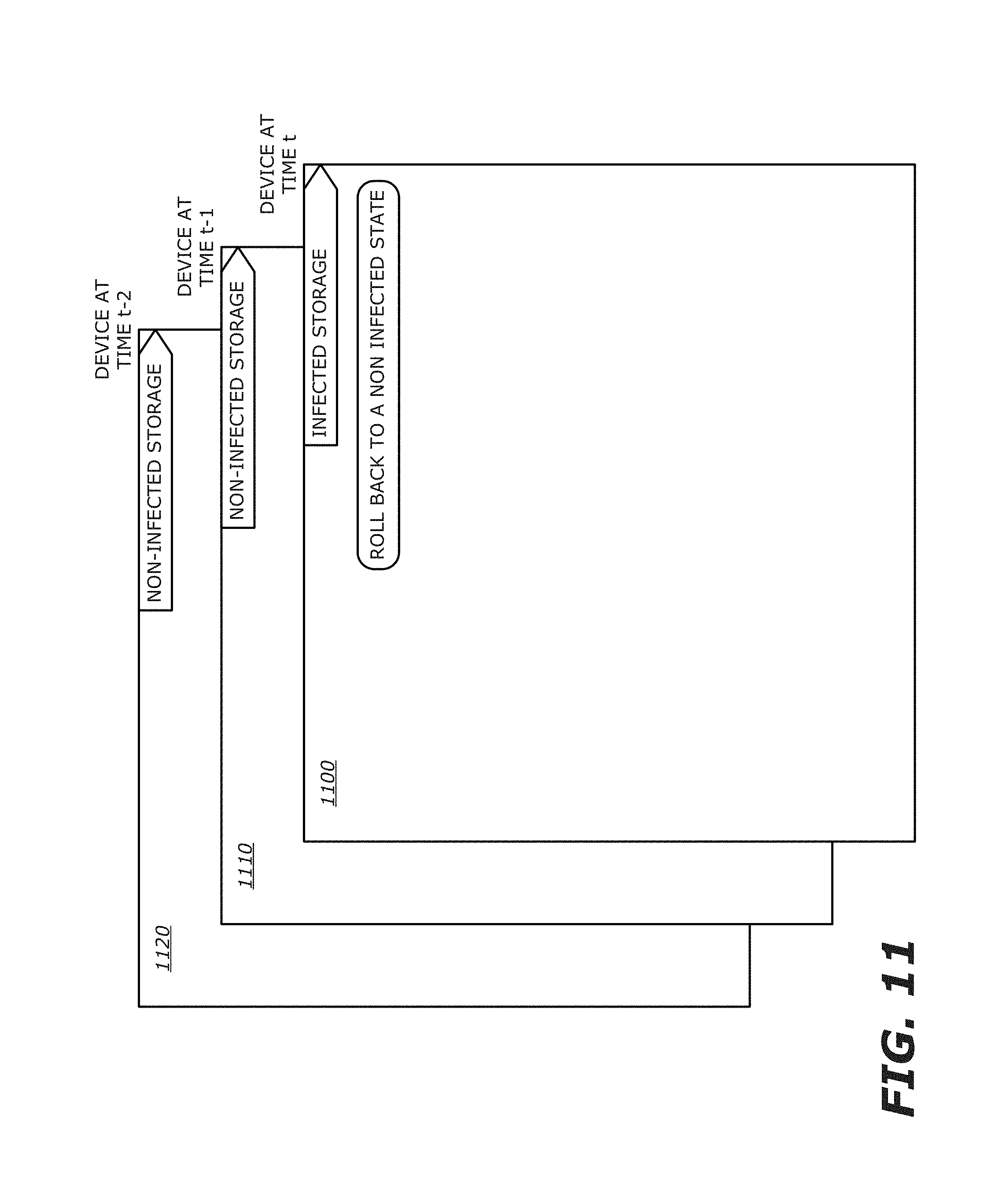
D00014

XML
uspto.report is an independent third-party trademark research tool that is not affiliated, endorsed, or sponsored by the United States Patent and Trademark Office (USPTO) or any other governmental organization. The information provided by uspto.report is based on publicly available data at the time of writing and is intended for informational purposes only.
While we strive to provide accurate and up-to-date information, we do not guarantee the accuracy, completeness, reliability, or suitability of the information displayed on this site. The use of this site is at your own risk. Any reliance you place on such information is therefore strictly at your own risk.
All official trademark data, including owner information, should be verified by visiting the official USPTO website at www.uspto.gov. This site is not intended to replace professional legal advice and should not be used as a substitute for consulting with a legal professional who is knowledgeable about trademark law.