Deep non-frangible stress profiles and methods of making
Oram , et al.
U.S. patent number 10,239,784 [Application Number 14/932,411] was granted by the patent office on 2019-03-26 for deep non-frangible stress profiles and methods of making. This patent grant is currently assigned to Corning Incorporated. The grantee listed for this patent is CORNING INCORPORATED. Invention is credited to Pascale Oram, Rostislav Vatchev Roussev, Vitor Marino Schneider, Emily Elizabeth Young.


| United States Patent | 10,239,784 |
| Oram , et al. | March 26, 2019 |
| **Please see images for: ( Certificate of Correction ) ** |
Deep non-frangible stress profiles and methods of making
Abstract
A non-frangible glass article strengthened by a dual or two-step ion exchange (IOX) process, where the first IOX step leads to a depth of compressive layer FSM_DOL>0.1t or, in some embodiments, FSM_DOL>0.15t, where t is the thickness of the glass, is provided. The glass article has a compressive stress CS1 after the first IOX step at the surface of from 100 MPa to 400 MPa or, in some embodiments, from 150 MPa to 300 MPa. The first IOX step is followed by a second IOX step, leading to a "spike" compressive stress CS2 after the second IOX step at the surface of greater than 500 MPa or, in some embodiments, 700 MPa. The width of the spike generated by the second IOX is between 1 .mu.m and 30 .mu.m, or between 8 .mu.m and 15 .mu.m, using the criteria where the magnitude (absolute value) of the slope of the spike is higher than 20 MPa/.mu.m.
| Inventors: | Oram; Pascale (Painted Post, NY), Roussev; Rostislav Vatchev (Painted Post, NY), Schneider; Vitor Marino (Painted Post, NY), Young; Emily Elizabeth (Erin, NY) | ||||||||||
|---|---|---|---|---|---|---|---|---|---|---|---|
| Applicant: |
|
||||||||||
| Assignee: | Corning Incorporated (Corning,
NY) |
||||||||||
| Family ID: | 54548277 | ||||||||||
| Appl. No.: | 14/932,411 | ||||||||||
| Filed: | November 4, 2015 |
Prior Publication Data
| Document Identifier | Publication Date | |
|---|---|---|
| US 20160122240 A1 | May 5, 2016 | |
Related U.S. Patent Documents
| Application Number | Filing Date | Patent Number | Issue Date | ||
|---|---|---|---|---|---|
| 62074872 | Nov 4, 2014 | ||||
| Current U.S. Class: | 1/1 |
| Current CPC Class: | C03C 21/002 (20130101); C03C 3/097 (20130101) |
| Current International Class: | C03C 3/097 (20060101); C03C 21/00 (20060101) |
References Cited [Referenced By]
U.S. Patent Documents
| 3433611 | March 1969 | Kubichan |
| 3798013 | March 1974 | Inoue et al. |
| 3936287 | February 1976 | Beall et al. |
| 4042405 | August 1977 | Krohn et al. |
| 4736981 | February 1988 | Pierson et al. |
| 5350607 | September 1994 | Tyson et al. |
| 5773148 | June 1998 | Charrue et al. |
| 5895768 | April 1999 | Speit |
| 6111821 | August 2000 | Bach |
| 8158543 | April 2012 | Dejneka et al. |
| 8312789 | November 2012 | Beck |
| 8349455 | January 2013 | Kondo et al. |
| 8415013 | April 2013 | Barefoot et al. |
| 8431502 | April 2013 | Dejneka et al. |
| 8561429 | October 2013 | Allan et al. |
| 8586492 | November 2013 | Barefoot et al. |
| 8623776 | January 2014 | Dejneka et al. |
| 8652978 | February 2014 | Dejneka et al. |
| 8756262 | June 2014 | Zhang |
| 8783063 | July 2014 | Osakabe et al. |
| 8802581 | August 2014 | Dejneka et al. |
| 8946103 | February 2015 | Dejneka et al. |
| 8951927 | February 2015 | Dejneka et al. |
| 8957374 | February 2015 | Liu et al. |
| 8969226 | March 2015 | Dejneka et al. |
| 9140543 | September 2015 | Allan et al. |
| 9156724 | October 2015 | Gross |
| 9290407 | March 2016 | Barefoot et al. |
| 9290413 | March 2016 | Dejneka et al. |
| 2005/0250639 | November 2005 | Siebers et al. |
| 2007/0060465 | March 2007 | Varshneya et al. |
| 2009/0197088 | August 2009 | Murata |
| 2010/0003508 | January 2010 | Arrouy et al. |
| 2010/0028607 | February 2010 | Lee et al. |
| 2010/0087307 | April 2010 | Murata et al. |
| 2010/0119846 | May 2010 | Sawada |
| 2011/0014475 | January 2011 | Murata |
| 2011/0165393 | July 2011 | Bayne et al. |
| 2011/0226832 | September 2011 | Bayne et al. |
| 2011/0294649 | December 2011 | Gomez |
| 2012/0052271 | March 2012 | Gomez et al. |
| 2012/0052275 | March 2012 | Hashimoto et al. |
| 2012/0135153 | May 2012 | Osakabe et al. |
| 2012/0135226 | May 2012 | Bookbinder et al. |
| 2012/0171497 | July 2012 | Koyama et al. |
| 2012/0196110 | August 2012 | Murata et al. |
| 2012/0219792 | August 2012 | Yamamoto et al. |
| 2012/0308827 | December 2012 | Boek et al. |
| 2012/0321898 | December 2012 | Meinhardt et al. |
| 2013/0017380 | January 2013 | Murata et al. |
| 2013/0045375 | February 2013 | Gross |
| 2013/0101798 | April 2013 | Hashimoto |
| 2013/0122260 | May 2013 | Liang |
| 2013/0122284 | May 2013 | Gross |
| 2013/0183512 | July 2013 | Gy et al. |
| 2013/0202868 | August 2013 | Barefoot et al. |
| 2013/0224492 | August 2013 | Bookbinder |
| 2013/0236666 | September 2013 | Bookbinder et al. |
| 2013/0236699 | September 2013 | Prest et al. |
| 2013/0240025 | September 2013 | Bersano et al. |
| 2013/0309613 | November 2013 | O'Malley et al. |
| 2014/0050911 | February 2014 | Mauro et al. |
| 2014/0087159 | March 2014 | Cleary et al. |
| 2014/0106172 | April 2014 | Dejneka et al. |
| 2014/0113141 | April 2014 | Yamamoto et al. |
| 2014/0139978 | May 2014 | Kwong |
| 2014/0150525 | June 2014 | Okawa et al. |
| 2014/0193606 | July 2014 | Kwong |
| 2014/0370264 | December 2014 | Ohara et al. |
| 2015/0030834 | January 2015 | Morey et al. |
| 2015/0030838 | January 2015 | Sellier et al. |
| 2015/0132563 | May 2015 | O'Malley et al. |
| 2015/0147575 | May 2015 | Dejneka et al. |
| 2015/0183680 | July 2015 | Barefoot et al. |
| 2015/0239775 | August 2015 | Amin et al. |
| 2015/0239776 | August 2015 | Amin et al. |
| 2015/0259244 | September 2015 | Amin et al. |
| 2015/0368148 | December 2015 | Duffy et al. |
| 2015/0368153 | December 2015 | Pesansky et al. |
| 700879 | Mar 1996 | EP | |||
| 2415724 | Feb 2012 | EP | |||
| 1334828 | Oct 1973 | GB | |||
| 2009099239 | May 2009 | JP | |||
| 2010202514 | Sep 2010 | JP | |||
| 2011213576 | Oct 2011 | JP | |||
| 2005091021 | Sep 2005 | WO | |||
| 2010005578 | Jan 2010 | WO | |||
| 2011077756 | Jun 2011 | WO | |||
| 2011149811 | Dec 2011 | WO | |||
| 2012074983 | Jun 2012 | WO | |||
| 2012126394 | Sep 2012 | WO | |||
| 2013088856 | Jun 2013 | WO | |||
| 2013136013 | Sep 2013 | WO | |||
| 2013184205 | Dec 2013 | WO | |||
| 2015127483 | Aug 2015 | WO | |||
| 2016070048 | May 2016 | WO | |||
Other References
|
Aegerter et al "Sol-gel technologies for glass producers and users--Chapter 4.1.8--Scratch resistant coatings (G. Helsch and G. H. Frischat)", pp. 217-221, Kluwer Academic Publishers, 2004. cited by applicant . Amin et al; U.S. Appl. No. 14/926,425, filed Oct. 29, 2015, titled "Strengthened Glass With Ultra-Deep Depth of Compression". cited by applicant . Bahlawane "Novel sol-gel process depositing a-Al2O3 for the improvement of graphite oxidation-resistance"--Thin Solid Films, vol. 396, pp. 126-130, 2001. cited by applicant . Dessler et al; "Differences between films and monoliths of sol-gel derived aluminas", Thin Solid Films, vol. 519, pp. 42-51, 2010. cited by applicant . Fu, et al, "Preparation of alumina films from a new sol-gel route" Thin Solid films 348, pp. 99-102 (1999). cited by applicant . Hauk "Sol-gel preparation of scratch-resistant Al2O3 coatings on float glass", Glass Science and Technology: Glastechnische Berichte, 72(12), pp. 386, 1999. cited by applicant . International Search Report and the Written Opinoin of the International Searching Authority; PCT/US2015/035448; dated Sep. 18, 2015; 11 Pages. cited by applicant . Oram et al; U.S. Appl. No. 14/932,411, filed Nov. 4, 2015, Titled "Deep Non-Frangible Stress Profiles and Methods of Making". cited by applicant . International Search Report and Written Opinion of the International Searching Authority; PCT/US2015/023507; dated Oct. 19, 2015; 19 Pages. cited by applicant . International Search Report and Written Opinion of the International Searching Authority; PCT/US2015/034996 dated Jan. 4, 2016; 13 Pages. cited by applicant . International Search Report and Written Opinion of the International Searching Authority; PCT/US2015/058322 dated Jan. 8, 2016; 14 Pages. cited by applicant . International Search Report and Written Opinion of the International Searching Authority; PCT/US2015/058919;dated Jan. 11, 2016; 11 Pages. cited by applicant . International Search Report and Written Opinion of the International Searching Authority; PCTUS2015041976; dated Oct. 29, 2015; 11 Pages. cited by applicant . Pflitsch et al; "Sol-gel deposition of chromium doped aluminum oxide films (Ruby) for surface temperature sensor application", Chem. Mater., vol. 20, pp. 2773-2778, 2008. cited by applicant . Stosser et al "Magnetic Resonance investigation of the process of corundum formation starting from sol-gel precursors", J. Am. Ceram. Soc, vol. 88, No. 10, pp. 2913-2922, 2005. cited by applicant . International Search Report and Written Opinion PCT/US2016/034634 dated Nov. 2, 2016. cited by applicant . ASTM C1279-13 "Standard Test Method for Non-Destructive Photoelastic Measurement of Edge and Surface Stresses in Annealed, Heat-Strengthened, and Fully Tempered Flat Glass"; Downloaded Jan. 24, 2018; 11 Pages. cited by applicant . ASTM C1422/C1422M-10 "Standard Specification for Chemically Strengthened Flat Glass"; Downloaded Jan. 24, 2018; 5 pages. cited by applicant. |
Primary Examiner: Boyle; Robert C
Attorney, Agent or Firm: Schaeberle; Timothy M. Schmidt; Jeffrey A.
Parent Case Text
This application claims the benefit of priority under 35 U.S.C. .sctn. 119 of U.S. Provisional Application Ser. No. 62/074,872 filed on Nov. 4, 2014 the content of which is relied upon and incorporated herein by reference in its entirety.
Claims
The invention claimed is:
1. A glass article comprising: a thickness tin a range from 0.4 mm to about 1.5 mm, a center at t/2, a compressive layer extending from a surface of the glass article to a depth of compression DOC as measured by the inverse Wentzel-Kramers-Brouillon (IWKB) method, and a tensile region under a physical center tension CT extending from the DOC to the center, wherein: a. the physical center tension CT as measured by the IWKB method in MPa is greater than |-1.956.times.10.sup.-16.times.t.sup.6+1.24274.times.10.sup.-12.times.t.s- up.5-3.09196.times.10.sup.-9.times.t.sup.4+3.80391.times.10.sup.-6.times.t- .sup.3-2.35207.times.10.sup.-3.times.t.sup.2+5.96241.times.10.sup.-1.times- .t+36.5994|, wherein t is in microns; and b. the glass article has a total elastic energy normalized per thickness of the glass E.sub.total, wherein (E.sub.total/t(mm)) is less than or equal to 174.75 J/m.sup.2mm.
2. The glass article of claim 1, wherein the thickness is 0.8 mm, the physical center tension CT is greater than |45 MPa|, and the total elastic energy E.sub.total is less than about 139.8 J/m.sup.2.
3. The glass article of claim 1, wherein the thickness is 0.5 mm, the physical center tension CT is greater than |63 MPa|, and the total elastic energy E.sub.total is less than 87.4 J/m.sup.2.
4. A glass article comprising: a thickness tin a range from about 0.4 mm to about 1 mm, a compressive layer extending from a surface of the glass article to a depth of compression DOC as measured by the inverse Wentzel-Kramers-Brouillon (IWKB) method, a center at t/2, and a tensile region under a physical center tension CT extending from the DOC to the center of the glass, wherein: a. the physical center tension CT as measured by the IWKB method in MPa is greater than |-1.956.times.10.sup.-16.times.t.sup.6+1.24274.times.10.sup.-12.times.t.s- up.5-3.09196.times.10.sup.-9.times.t.sup.4+3.80391.times.10.sup.-6.times.t- .sup.3-2.35207.times.10.sup.-3.times.t.sup.2+5.96241.times.10.sup.-1.times- .t+36.5994|, wherein t is in microns; and b. the glass article has an elastic energy stored in the interior of the sample in tension of E.sub.interior, wherein (E.sub.interior/t(mm)) is less than or equal to 30 J/m.sup.2mm.
5. The glass article of claim 4, wherein the thickness is 0.8 mm, the physical center tension CT is greater than |45 MPa| and E.sub.interior is less than about 24 J/m.sup.2.
6. The glass article of claim 4, wherein the thickness is 0.5 mm, the physical center tension CT is greater than |63 MPa| and E.sub.interior is less than about 18 J/m.sup.2.
7. The glass article of claim 1, further comprising a stress profile as measured by the IWKB method having a spike region extending from the surface to a depth less than the DOC, the spike region having a slope, wherein the slope has an absolute value of greater than about 20 MPa/.mu.m.
8. The glass article of claim 1, further comprising a stress profile as measured by the IWKB method having a spike region extending from the surface to about less than or equal to 30 .mu.m below the surface.
9. The glass article of claim 4, further comprising a stress profile as measured by the IWKB method having a spike region extending from the surface to about less than or equal to 30 .mu.m below the surface.
10. The glass article of claim 4, wherein the DOC is greater than 0.1*t.
11. An electronic device comprising the glass article of claim 1.
12. An electronic device comprising the glass article of claim 4.
Description
BACKGROUND
The disclosure relates to stress profiles in glasses. More particularly, the disclosure relates to glasses having deep compressive stress profiles. Even more particularly, the disclosure relates to glasses having deep compressive stress profiles and exhibiting non-frangible behavior.
Chemically strengthened glasses are widely used in displays for hand-held electronic devices such as phones, notebooks and the like. Chemical strengthening creates a compressive layer at the surface of the glass and a tensile region in the central portion of the glass. Compressive stress (CS) and depth of layer (DOL) are typically determined from surface stress measurements (FSM) using commercially available instruments such as, for example, the FSM-6000, surface stress meter manufactured by Luceo Co., Ltd. (Tokyo, Japan) or the like.
For strengthened glass articles in which the compressive stress layers extend to deeper depths within the glass, the FSM technique may suffer from contrast issues that affect the observed DOL. At deeper DOL values, there may be inadequate contrast between the TE and TM spectra, thus making the calculation of the difference between TE and TM spectra--and accurately determining the DOL--more difficult. Moreover, the FSM software analysis is incapable of determining the compressive stress profile (i.e., the variation of compressive stress as a function of depth within the glass). In addition, the FSM technique is incapable of determining the depth of layer resulting from the ion exchange of certain elements such as, for example, ion exchange of sodium for lithium, that are present in the glass.
SUMMARY
The present disclosure extends the range of possible compressive stress profiles. Modifications to metrology based on the Orihara FSM instrument have enabled measurement of are chemically strengthened glasses with "super-deep" depth of compressive layer DOL; i.e., glass samples having a depth of compressive layer of greater than about 120 .mu.m and, in some embodiments, greater than about 140 .mu.m with standard deviation around 4 .mu.m, as determined by surface stress/FSM measurements (referred to herein as "FSM_DOL" or simply "DOL"). In some embodiments, the DOL may be about 186 .mu.m with a standard deviation of about 10 .mu.m have been obtained. The glasses are non-frangible--i.e., the glasses do not exhibit frangible (explosive or energetic fragmentation) behavior upon impact or insult.
Accordingly, in one aspect, a strengthened glass article is provided. The glass article has a thickness t and a compressive layer extending from a surface of the glass article to a depth of layer DOL of greater 0.1t. The glass article has a maximum compressive stress CS of greater than about 500 MPa at the surface, a stress profile having a spike region in a range from about 1 .mu.m to about 30 .mu.m. The stress profile in the spike region has a slope. The slope has an absolute value of greater than about 20 MPa/.mu.m.
In another aspect, a glass article having a thickness t in a range from about 0.2 mm to about 1.5 mm, a compressive layer extending from a surface of the glass article to a depth of layer DOL or depth of compression DOC, and a tensile region under a physical center tension CT extending from the depth of layer or depth of compression to the center of the glass at t/2 is provided. The physical center tension CT is greater than |-1.956.times.10.sup.-16.times.t.sup.6+1.24274.times.10.sup.-12.times.t.s- up.5-3.09196.times.10.sup.-9.times.t.sup.4+3.380391.times.10.sup.-6.times.- t.sup.3-2.35207.times.10.sup.-3.times.t.sup.2+5.96241.times.10.sup.-1.time- s.t+36.5994|, and the glass article has a total elastic energy normalized per thickness of the glass E.sub.total, wherein (E.sub.total/t)=174.75 J/m.sup.2mm.
In yet another aspect, a glass article having a thickness t in a range from about 0.3 mm to about 1 mm, a compressive layer extending from a surface of the glass article to a depth of layer DOL or depth of compression DOC, and a tensile region under a physical center tension CT extending from the depth of layer or depth of compression to the center of the glass at t/2 is provided. The physical center tension CT is greater than |-1.956.times.10.sup.-16.times.t.sup.6+1.24274.times.10.sup.-12.times.t.s- up.5-3.09196.times.10.sup.-9.times.t.sup.4+3.80391.times.10.sup.-6.times.t- .sup.3-2.35207.times.10.sup.-3.times.t.sup.2+5.96241.times.10.sup.-1.times- .t+36.5994|, and has an elastic energy stored in the interior of the sample in tension of E.sub.interior, wherein (E.sub.interior/t)=30 J/m.sup.2mm.
In another aspect, a glass article strengthened by a two-step ion exchange (IOX) process and having a stress profile is provided. The glass article has a thickness t in a range from about 0.4 mm to about 1 mm and a center at t/2, a compressive layer extending from a surface of the glass article to a depth of layer DOL or a depth of compression DOC, and a tensile region under a physical center tension CT extending from the depth of layer to the center of the glass article. The glass article has a compressive stress CS1 after the first ion exchange step at the surface of from 100 MPa to 400 MPa and, in some embodiments, from 150 MPa to 300 MPa, and a depth of layer FSM_DOL greater than 0.14 or, in some embodiments, greater than 0.15t following the first ion exchange step. The first ion exchange step is followed by a second ion exchange step after which the glass article has a compressive stress CS2 of greater than about than 500 MPa or, in some embodiments, greater than 700 MPa, at the surface and has a stress profile having a spike region in a range from about the surface to about 30 .mu.m or, in some embodiments, to about 8 .mu.m-15 .mu.m. The stress profile in the spike region has a slope, which has an absolute value of greater than about 20 MPa/.mu.m.
A method of strengthening a glass article is also provided. The glass article has a thickness t and a center at t/2. The method comprises: ion exchanging the glass article in a first ion exchange bath comprising a potassium salt and at least 30 wt % of a sodium salt to form a compressive layer having a compressive stress CS1 at the surface of from about 100 MPa to about 400 MPa, the compressive layer extending from a surface of the glass article to a depth of layer FSM_DOL of greater than 0.1t, or depth of compression DOC, and a tensile region under a physical center tension CT extending from the depth of layer or depth of compression to the center of the glass article; and ion exchanging the glass article in a second ion exchange bath comprising at least 90 wt % of a potassium salt to form a spike region extending from the surface to about 30 .mu.m below the surface. The spike region has a maximum compressive stress CS of greater than about 500 MPa at the surface, wherein the stress profile in the spike region has a slope, the slope having an absolute value of greater than about 20 MPa/.mu.m.
These and other aspects, advantages, and salient features of the present disclosure will become apparent from the following detailed description, the accompanying drawings, and the appended claims.
BRIEF DESCRIPTION OF THE DRAWINGS
FIG. 1 is a plot of typical values of physical center tension (MPa) limits as a function of sample thickness;
FIG. 2 is a plot of a stress profile of a double ion exchange sample;
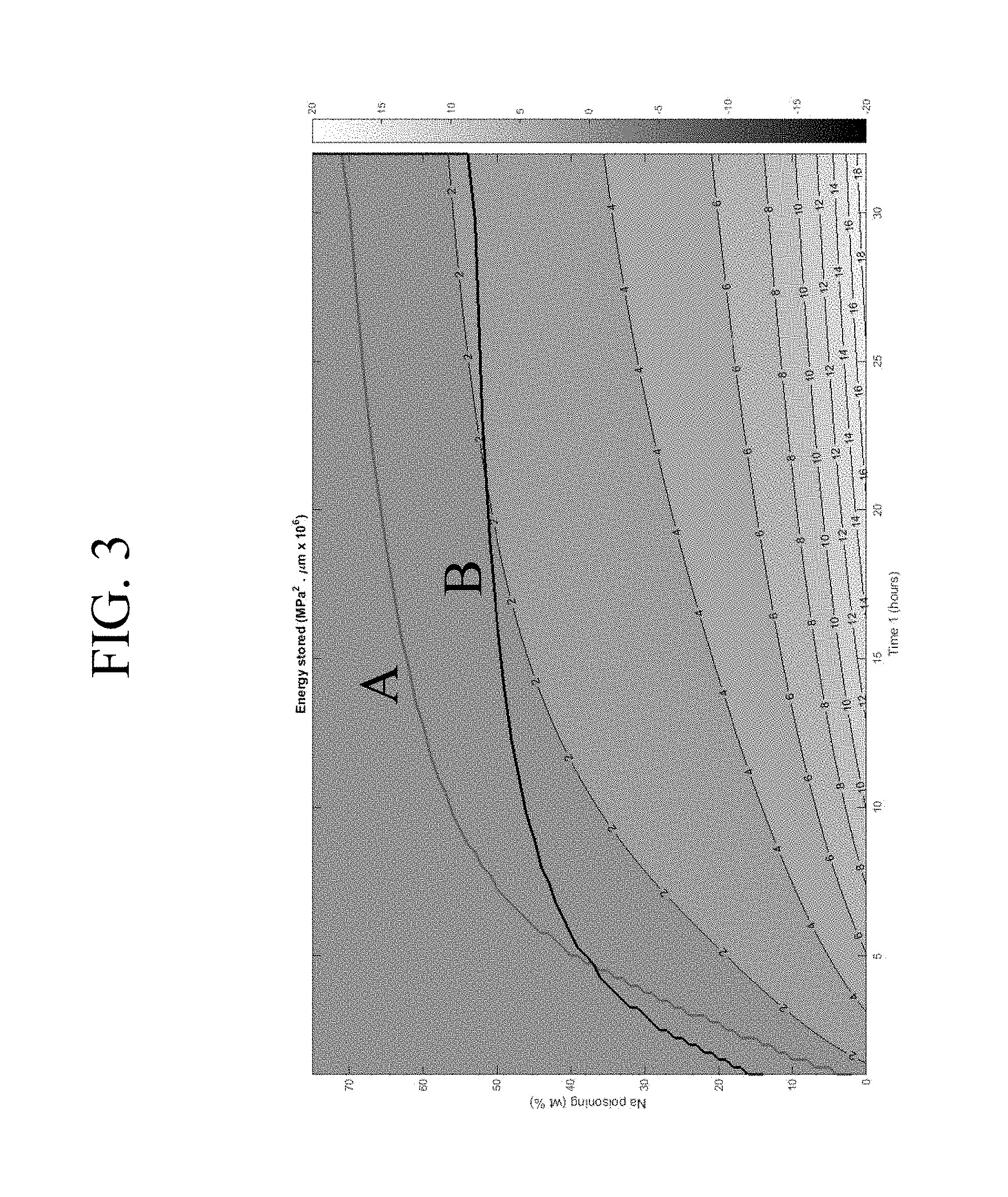
FIG. 3 is a map of the area of interest for an alkali aluminosilicate glass having a Poisson ratio .nu.=65 GPa and a Young's modulus E=65 GPa;
FIG. 4 is a second map of the area of interest for the case of an alkali aluminosilicate glass which has a Poisson ratio .nu.=65 GPa and a Young's modulus E=65 GPa;
FIG. 5 is an example of a compressive stress profile for a non-frangible glass sample strengthened using a first ion exchange step of 32.1 hours at a temperature of 460.degree. C. in a bath containing 57 wt % NaNO.sub.3 and 53 wt % KNO.sub.3; and
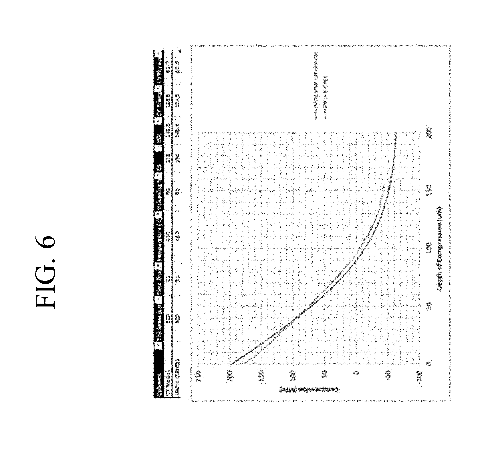
FIG. 6 is an example of a compressive stress profile for a glass having a thickness of 500 .mu.m.
DETAILED DESCRIPTION
In the following description, like reference characters designate like or corresponding parts throughout the several views shown in the figures. It is also understood that, unless otherwise specified, terms such as "top," "bottom," "outward," "inward," and the like are words of convenience and are not to be construed as limiting terms. In addition, whenever a group is described as comprising at least one of a group of elements and combinations thereof, it is understood that the group may comprise, consist essentially of, or consist of any number of those elements recited, either individually or in combination with each other. Similarly, whenever a group is described as consisting of at least one of a group of elements or combinations thereof, it is understood that the group may consist of any number of those elements recited, either individually or in combination with each other. Unless otherwise specified, a range of values, when recited, includes both the upper and lower limits of the range as well as any ranges therebetween. As used herein, the indefinite articles "a," "an," and the corresponding definite article "the" mean "at least one" or "one or more," unless otherwise specified. It also is understood that the various features disclosed in the specification and the drawings can be used in any and all combinations.
As used herein, the terms "glass article" and "glass articles" are used in their broadest sense to include any object made wholly or partly of glass. Unless otherwise specified, all compositions are expressed in terms of mole percent (mol %).
It is noted that the terms "substantially" and "about" may be utilized herein to represent the inherent degree of uncertainty that may be attributed to any quantitative comparison, value, measurement, or other representation. These terms are also utilized herein to represent the degree by which a quantitative representation may vary from a stated reference without resulting in a change in the basic function of the subject matter at issue. Thus, a glass that is "substantially free of MgO" is one in which MgO is not actively added or batched into the glass, but may be present in very small amounts as a contaminant e.g., less than about 0.1 mol %.
Referring to the drawings in general and to FIG. 1 in particular, it will be understood that the illustrations are for the purpose of describing particular embodiments and are not intended to limit the disclosure or appended claims thereto. The drawings are not necessarily to scale, and certain features and certain views of the drawings may be shown exaggerated in scale or in schematic in the interest of clarity and conciseness.
Described herein are chemically strengthened glasses with "super-deep" DOL; i.e., glass samples having a depth of compressive layer of greater than about 120 .mu.m and, in some embodiments, greater than about 140 .mu.m, with a standard deviation around 4 .mu.m, as determined by surface stress/FSM measurements (referred to herein as "FSM_DOL" or simply "DOL"). In some embodiments, the DOL may be about 186 .mu.m with a standard deviation of about 10 .mu.m.
The glasses described herein are ion exchangeable alkali aluminosilicate glasses, which, in some embodiments, are formable by down-draw processes, such as slot-draw, or fusion-draw processes that are known in the art. In particular embodiments, such glasses may have a liquidus viscosity of at least about 100 kiloPoise (kP), or at least about 130 kP. In one embodiment, the alkali aluminosilicate glass comprises SiO.sub.2, Al.sub.2O.sub.3, P.sub.2O.sub.5, and at least one alkali metal oxide (R.sub.2O), wherein 0.75.ltoreq.[P.sub.2O.sub.5 (mol %)+R.sub.2O (mol %))/M.sub.2O.sub.3 (mol %)].ltoreq.1.2, where M.sub.2O.sub.3=Al.sub.2O.sub.3+B.sub.2O.sub.3. In some embodiments, the alkali aluminosilicate glass comprises or consists essentially of: from about 40 mol % to about 70 mol % SiO.sub.2; from 0 mol % to about 28 mol % B.sub.2O.sub.3; from 0 mol % to about 28 mol % Al.sub.2O.sub.3; from about 1 mol % to about 14 mol % P.sub.2O.sub.5; and from about 12 mol % to about 16 mol % R.sub.2O and, in certain embodiments, from about 40 to about 64 mol % SiO.sub.2; from 0 mol % to about 8 mol % B.sub.2O.sub.3; from about 16 mol % to about 28 mol % Al.sub.2O.sub.3; from about 2 mol % to about 12 mol % P.sub.2O.sub.5; and from about 12 mol % to about 16 mol % R.sub.2O. In some embodiments, 11 mol %.ltoreq.M.sub.2O.sub.3.ltoreq.30 mol %; in some embodiments, 13 mol %.ltoreq.R.sub.xO.ltoreq.30 mol %, where R.sub.xO is the sum of alkali metal oxides, alkaline earth metal oxides, and transition metal monoxides present in the glass; and in still other embodiments, the glass is lithium-free. These glasses are described in patent application Ser. No. 13/305,271, entitled "Ion Exchangeable Glass with Deep Compressive Layer and High Damage Threshold," filed Nov. 28, 2011, by Dana Craig Bookbinder et al. and claiming priority from U.S. provisional patent application No. 61/417,941, filed on Nov. 30, 2010, and having the same title, the contents of which are incorporated herein by reference in their entirety.
In certain embodiments, the alkali aluminosilicate glass comprises at least about 4 mol % P.sub.2O.sub.5, wherein (M.sub.2O.sub.3 (mol %)/R.sub.xO(mol %))<1, wherein M.sub.2O.sub.3=Al.sub.2O.sub.3+B.sub.2O.sub.3, and wherein R.sub.xO is the sum of monovalent and divalent cation oxides present in the alkali aluminosilicate glass. In some embodiments, the monovalent and divalent cation oxides are selected from the group consisting of Li.sub.2O, Na.sub.2O, K.sub.2O, Rb.sub.2O, Cs.sub.2O, MgO, CaO, SrO, BaO, and ZnO. In some embodiments, the glass is lithium-free and consists essentially of from about 40 mol % to about 70 mol % SiO.sub.2; from about 11 mol % to about 25 mol % Al.sub.2O.sub.3; from about 4 mol % to about 15 mol % P.sub.2O.sub.5; from about 13 mol % to about 25 mol % Na.sub.2O; from about 13 to about 30 mol % R.sub.xO, where R.sub.xO is the sum of the alkali metal oxides, alkaline earth metal oxides, and transition metal monoxides present in the glass; from about 11 to about 30 mol % M.sub.2O.sub.3, where M.sub.2O.sub.3=Al.sub.2O.sub.3+B.sub.2O.sub.3; from 0 mol % to about 1 mol % K.sub.2O; from 0 mol % to about 4 mol % B.sub.2O.sub.3, and 3 mol % or less of one or more of TiO.sub.2, MnO, Nb.sub.2O.sub.5, MoO.sub.3, Ta.sub.2O.sub.5, WO.sub.3, ZrO.sub.2, Y.sub.2O.sub.3, La.sub.2O.sub.3, HfO.sub.2, CdO, SnO.sub.2, Fe.sub.2O.sub.3, CeO.sub.2, As.sub.2O.sub.3, Sb.sub.2O.sub.3, Cl, and Br; the glass is lithium-free; and 1.3<[(P.sub.2O.sub.5+R.sub.2O)/M.sub.2O.sub.3].ltoreq.2.3, where R.sub.2O is the sum of monovalent_cation oxides present in the glass. The glass is described in U.S. Pat. No. 9,156,724 by Timothy M. Gross, entitled "Ion Exchangeable Glass with High Crack Initiation Threshold," filed Nov. 15, 2012, and U.S. Pat. No. 8,756,262 by Timothy M. Gross, entitled "Ion Exchangeable Glass with High Crack Initiation Threshold," filed Nov. 15, 2012, both claiming priority to U.S. Provisional Patent Application No. 61/560,434 filed Nov. 16, 2011. The contents of the above patent and applications are incorporated herein by reference in their entirety.
Glass samples with super-deep DOL .mu.m were chemically strengthened in ion exchange baths having different "poisoning" levels--i.e., baths of a potassium salt "poisoned" with a sodium salt), and a number of them were found not to exhibit frangible behavior (explosive and energetic fragmentation upon impact or insult, often delayed) despite exceeding what has been considered to be the center tension CT limit above which such behavior is typically observed, thus confirming that the total energy criteria drives frangibility in these cases. Accordingly, the glasses exhibit non-frangible behavior in a regime where such behavior is not expected.
Frangible behavior is characterized by at least one of: breaking of the strengthened glass article (e.g., a plate or sheet) into multiple small pieces (e.g., .ltoreq.1 mm); the number of fragments formed per unit area of the glass article; multiple crack branching from an initial crack in the glass article; violent ejection of at least one fragment to a specified distance (e.g., about 5 cm, or about 2 inches) from its original location; and combinations of any of the foregoing breaking (size and density), cracking, and ejecting behaviors. As used herein, the terms "frangible behavior" and "frangibility" refer to those modes of violent or energetic fragmentation of a strengthened glass article absent any external restraints, such as coatings, adhesive layers, or the like. While coatings, adhesive layers, and the like may be used in conjunction with the strengthened glass articles described herein, such external restraints are not used in determining the frangibility or frangible behavior of the glass articles.
Frangible behavior and non-frangible behavior of strengthened glass articles may be determined by a point impact test using an instrument such as, for example, a scribe with a tungsten carbide tip, that is delivered to the surface of the glass article with a force that is just sufficient to release the internally stored energy present within the strengthened glass article. That is, the point impact force is sufficient to create at least one new crack at the surface of the strengthened glass sheet and extend the crack through the compressive stress CS region (i.e., depth of layer) into the region that is under central tension CT.
Accordingly, the chemically strengthened glasses described herein are "non-frangible"--i.e., they do not exhibit frangible behavior as described hereinabove when subjected to impact by a sharp object.
Described herein are chemically strengthened glass articles for which FSM_DOL>0.1t and, in some embodiments, FSM_DOL>0.15t, where t is the thickness of the sample. The glasses are strengthened in an ion exchange bath containing a potassium salt that is "poisoned" with greater than about 30 wt % of a sodium salt such as NaNO.sub.3. The thickness t is in a range from about 400 .mu.m (0.4 mm) to about 2000 .mu.m (2 mm).
Samples may also be strengthened using a two-step ion exchange (double IOX) process to further increase the compressive stress at the surface of the glass and thus create a compressive stress "spike" at the surface and extending to a depth of about 30 lam below the surface, and a "super-deep" DOL of about 150 .mu.m without demonstrating frangibility.
Super-deep DOL samples using a double IOX process with a spike and FSM measured depth of layer FSM_DOL of greater than 120 .mu.m, in some embodiments, ranging from about 140 .mu.m to about 150 .mu.m, and, in still other embodiments, possibly reaching FSM_DOL of at least about 186 .mu.m are provided. These double ion-exchanged samples with a spike have a compressive stress maximum at in a range from about 800 MPa to about 900 MPa and are not frangible.
Compressive stress CS and depth of layer DOL are measured using those means known in the art. Such means include, but are not limited to, measurement of surface stress (FSM) using commercially available instruments such as the FSM-6000, manufactured by Luceo Co., Ltd. (Tokyo, Japan), or the like, and methods of measuring compressive stress and depth of layer are described in ASTM 1422C-99, entitled "Standard Specification for Chemically Strengthened Flat Glass," and ASTM 1279.19779 "Standard Test Method for Non-Destructive Photoelastic Measurement of Edge and Surface Stresses in Annealed, Heat-Strengthened, and Fully-Tempered Flat Glass," the contents of which are incorporated herein by reference in their entirety. Surface stress measurements rely upon the accurate measurement of the stress optical coefficient (SOC), which is related to the birefringence of the glass. SOC in turn is measured by those methods that are known in the art, such as fiber and four point bend methods, both of which are described in ASTM standard C770-98 (2008), entitled "Standard Test Method for Measurement of Glass Stress-Optical Coefficient," the contents of which are incorporated herein by reference in their entirety, and a bulk cylinder method.
As used herein, the terms "DOL" and "FSM_DOL" refer to the depth of the compressive layer as determined by surface stress measurements.
For strengthened glass articles in which the compressive stress layers extend to deeper depths within the glass, the FSM technique may suffer from contrast issues that affect the observed DOL value. At deeper depths of compressive layer, there may be inadequate contrast between the TE and TM spectra, thus making the calculation of the difference between the spectra of bound optical modes for TM and TE polarization--and accurate determination the DOL--more difficult. Moreover, the FSM software analysis is incapable of determining the compressive stress profile (i.e., the variation of compressive stress as a function of depth within the glass). In addition, the FSM technique is incapable of determining the depth of layer resulting from the ion exchange of certain elements in the glass such as, for example, the ion exchange of sodium for lithium.
The DOL as determined by the FSM is a relatively good approximation for the depth of compression (DOC) when the DOL is a small fraction r of the thickness t and the index profile has a depth distribution that is reasonably well approximated with a simple linear truncated profile. When the DOL is a substantial fraction of the thickness, such as DOL.gtoreq.0.1t, then the DOC is most often noticeably lower than the DOL. For example, in the idealized case of a linear truncated profile, the relationship DOC=DOL(1-r) holds, where r=DOL/t.
The depth of compression Physical_DOL, also known as IWKB_DOL or DOCL (depth of compression layer) is determined from the spectra of bound optical modes for TM and TE polarization by using the inverse Wentzel-Kramers-Brillouin (IWKB) method. As used herein, Physical_DOL refers to the depth at which the stress is effectively zero inside the glass. This Physical_DOL is typically less than the FSM_DOL measured by the FSM instrument for a single Ion exchange process. For double ion exchange processes, the measured FSM_DOL is not a reliable metric, due to the nature of the instrument and its processing algorithm.
The shape and values of the stress profile in an ion exchanged glass are limited by a known frangibility limit. This frangibility limit is usually expressed in terms of the center tension CT, which is the value of the tensile stress in the center of the glass at the position x, where x=thickness/2. The center tension CT naturally occurs due to the force balance of the stress induced by the sample during the IOX process. The integral or sum of the stress at each point in the compressive part of the profile has to be equal to the integral or sum of the stress at each point in the tensile part of the profile, so that the sample is flat and not curved.
If one assumes a single IOX (SIOX) profile, diffusion is guided by a classical complementary error function. It has been found that the physical CT varies with glass thickness as shown in FIG. 1.
In FIG. 1, typical values of the physical center tension limit found as a function of the thickness of the sample for a SIOX is shown. A curve can be fit to the data in FIG. 1 to determine other physical center tension values between thicknesses of 200 .mu.m to 1200 .mu.m. The following equation may then be used to describe how classical physical CT values vary with thickness t, expressed in microns: CT=-1.956.times.10.sup.-16.times.t.sup.6+1.24274.times.10.sup.-12.times.t- .sup.5-3.09196.times.10.sup.-9.times.t.sup.4+3.80391.times.10.sup.-6.times- .t.sup.3-2.35207.times.10.sup.-3.times.t.sup.2+5.96241.times.10.sup.-1.tim- es.t+36.5994 (1).
When trying to find the ranges of values where a super-deep DOL sample can be made using a DIOX profile, another important parameter is the concept of elastic energy. A typical stress profile of a glass sample subjected to the double ion exchange (DIOX) process is schematically shown in FIG. 2. The energy stored in the surface is in compression and the energy stored in the interior of the sample is tension. The total energy E.sub.total is the sum of the energy in the surface plus the energy in the interior E.sub.interior of the sample. The factor of 2 in the equations shown in FIG. 2 indicates that both sides of the glass must be integrated and taken into account. The stress profile shown in FIG. 2 has a tail due to the first IOX step and a "spike" due to the second IOX step. The position of the spike occurs where the magnitude (i.e., absolute value) of the slope of the stress increases to a value of greater than about 20 MPa/.mu.m.
The elastic energy stored by the stress profile is calculated according to the equation
.times..intg..sigma..times..times..times. ##EQU00001## where .nu. is the Poisson ratio (0.22 for the example glass), E is Young's modulus (about 68 GPa for the example glass), and .sigma. is the stress.
The elastic energy (per unit area of glass) in each compression region (one on each outer surface) is:
.times..intg..times..sigma..times..times..times..times. ##EQU00002##
The elastic energy in the tension region from the compression depth to the center of the glass substrate is:
.times..intg..times..times..sigma..times..times..times..times. ##EQU00003##
The total elastic energy stored in the substrate is twice the sum of the elastic energy of the single compression region and the half tension region: W.sub.el.sup.tot=2(W.sub.el.sup.comp+W.sub.el.sup.tens) (5).
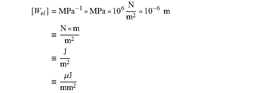
Units for the quantities found in equations 2-5 are:
for stress: [.sigma.]=MPa.ident.10.sup.6 N/m.sup.2;
for depth: [x]=.mu.m=10.sup.-6 m; and
for elastic energy (per unit substrate area):
.times..times..times..times..ident..times..ident..times..ident..times..mu- ..times..times. ##EQU00004##
Another metric is the elastic energy per unit substrate area per unit thickness of the substrate, expressed in terms of J/m.sup.2 mm. This is a more universal parameter because it is independent of the thickness of the glass sample. The elastic energy per thickness of the substrate is valid from thicknesses ranging from 50 .mu.m to 2000 .mu.m.
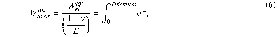
In one embodiment, a frangibility criterion may be introduced in the form of a normalized total energy, which defined as:
.intg..times..sigma. ##EQU00005##
Based on the above concepts, several double IOX experiments were performed on 0.8 mm thick alkali aluminosilicate glass, which is described in U.S. patent application Ser. No. 13/305,271, and has a nominal composition of about 57 mol % SiO.sub.2, 0 mol % B.sub.2O.sub.3, about 17 mol % Al.sub.2O.sub.3, about 7% P.sub.2O.sub.5, about 17 mol % Na.sub.2O, about 0.02 mol % K.sub.2O, and about 3 mol % MgO. Here, detailed stress profile extraction using an IWKB-based algorithm was employed. The method is described in U.S. Pat. No. 9,140,543, entitled "Systems and Methods for Measuring the Stress Profile of Ion-Exchanged Glass," filed May 3, 2012, by Douglas C. Allan et al. and claiming priority from U.S. provisional patent application No. 61/489,800, filed on May 25, 2011, and having the same title, the contents of which are incorporated herein by reference in their entirety. The above procedure allowed the approximated physical stress profile to be extracted and the Physical_DOL or depth of compression layer (DOCL) where the stress effectively crosses from compressive stress to tensile stress at--and equals--zero to be pinpointed. By balancing tensile and compressive forces across the sample, the physical CT may be computed. In addition, it is also possible to approximate the elastic energies in compression and tension, as well as the total elastic energy. In some embodiments, the Physical_DOL is greater than 0.8t and, in some embodiments, greater than 0.12t.
Examples of super-deep DOL obtained by the double or two-step IOX processes are listed in Tables 1a and 1b. Table 1a includes parameters (bath composition, temperature, ion exchange time) for the first and second ion exchange baths and compressive stresses CS and depths of layer DOL, measured by FSM, following each ion exchange step. Table 1b lists sample frangibility; depth of compression DOC, compressive stress CS, and physical center tension CT as determined by the IWKB treatment; compressive, tensile, and total energies, and total energy normalized for thickness. The glass samples listed in the tables each had a thickness of 800 .mu.m and the composition previously described hereinabove. All samples shown in Tables 1a and b are non-frangible, including some samples for which the physical CT as determined by the IWKB method is above the previously reported CT frangibility limit of CT.sub.max=-45 MPa for 800 .mu.m thick glass. These samples track the elastic energy in the sample more closely, and if the correct region of process parameters and stress profile targets of CS and DOL of the first and second ion exchange steps are targeted, super-deep depths of layer and compression that were previously believed to be unattainable may be achieved.
TABLE-US-00001 TABLE 1a Ion exchange parameters for the first and second ion exchange baths and compressive stresses CS and depths of layer DOL, measured by FSM for double-IOX processes (DIOX) for alkali aluminosilicate glass samples having a thickness of 800 .mu.m. IOX step 1 IOX step 2 Mean Mean Mean Mean CS1 DOL1 CS1 DOL1 wt % time Temp (FSM) (FSM) wt % time Temp (FSM) (FSM) Sample Na (h) (.degree. C.) [MPa] [.mu.m] Na (h) (.degree. C.) [MPa] [.mu.m] 1 57 15 460 201.5 136.6 0.5 0.25 390 201.5 136.6 2 57 17.5 460 196.7 148.7 0.5 0.25 390 196.7 148.7 3 57 20.1 460 195.8 154.8 0.5 0.25 390 195.8 154.8 4 57 26 460 194.2 163.8 0.5 0.25 390 194.2 163.8 5 57 28 460 192.8 176.6 0.5 0.25 390 192.8 176.6 6 57 32.1 460 189.1 180.4 0.5 0.25 390 189.1 180.4 7 49 15 460 245.5 143.8 0.5 0.25 390 245.5 143.8 8 49 17.25 460 242.0 157.0 0.5 0.25 390 242.0 157.0
TABLE-US-00002 TABLE 1b Sample frangibility; depth of compression DOC, compressive stress CS, and physical center tension CT as determined by the IWKB treatment; compressive, tensile, and total energies, and total energy normalized for thickness, determined for the double ion exchanged samples listed in Table 1a. IWKB IWKB IWKB Compressive Tensile Total Total DOC CS CT Energy Energy Energy Energy Sample Frangible (.mu.m) (MPa) (MPa) (J/m.sup.2) (J/m.sup.2) (J/m.sup.2) (- J/m.sup.2 mm) 1 no 96.81 921.38 -38.73 85.08 10.92 96.00 120.00 2 no 100.72 901.46 -40.17 85.47 11.59 97.06 121.33 3 no 107.92 927.36 -43.27 87.49 13.12 100.62 125.77 4 no 115.48 983.50 -46.46 91.15 14.74 105.89 132.36 5 no 117.53 956.90 -47.36 89.02 15.20 104.23 130.28 6 no 124.91 833.79 -50.87 88.14 17.09 105.23 131.54 7 no 103.57 948.16 -48.53 105.13 16.75 121.88 152.35 8 no 108.57 882.65 -51.09 101.20 18.26 119.47 149.33
The depths of layer DOL1 as measured with the FSM-6000 instrument for the first ion exchange step were in a range from 136.6 .mu.m to 180.4 .mu.m and the compressive stresses CS1 were in a range from 189 MPa to 245 MPa. Following the second IOX step, the CS peak or spike was the range from 852 MPa to 890 MPa. The spike extends from the surface to a depth of about 10 .mu.m to about 11 .mu.m. The peak width may, in practice, be somewhat controlled depending on the immersion time in the second IOX bath. Peak widths from about 1 .mu.m to 25 .mu.m and, in some embodiments, up to about 30 .mu.m are possible for the spike region, depending on the elastic energy stored in the sample.
For glass samples having the above composition with 800 .mu.m thickness, two regions of interest have been identified based on concepts of physical CT and elastic energy. The first region of interest is shown in FIG. 3, which is a map of an area of interest for a glass having a Poisson ratio .nu.=65 GPa and a Young's modulus E=65 GPa. The upper line A in FIG. 3 is the frangibility limit that has been believed to exist, where CT=-45 MPa for a 800 .mu.m thick sample. Line B in FIG. 3 is the normalized total energy, which is the integral of the stress squared. Line B is the lower limit with a value of E.sub.total=11.65 MPa.sup.2.mu.m.times.10.sup.6, and corresponds to a non-normalized total energy of E.sub.total=139.8 J/m.sup.2. Normalizing the thickness, (E.sub.totalt)=174.75 J/m.sup.2mm for thickness t=0.8 mm, which is a more universal value that is thickness independent. The area of interest is the area between lines A and B and can be described to be an area where Physical CT>|45 MPa| and E.sub.total<139.8 J/m.sup.2 for a thickness t=800 .mu.m. For a generic thickness, independent physical CT is greater than |-1.956.times.10.sup.-16.times.t.sup.6+1.24274.times.10.sup.-12.times.t.s- up.5-3.09196.times.10.sup.-9.times.t.sup.4+3.80391.times.10.sup.-6.times.t- .sup.3-2.35207.times.10.sup.-3.times.t.sup.2+5.96241.times.10.sup.-1.times- .t+36.5994|, where t is the thickness in microns and (E.sub.total/t)=174.75 J/m.sup.2mm, where t is the same thickness, expressed in millimeters, for any dual IOX profile. The parameters described by the area between lies A and B in FIG. 3 describe the poisoning level and ion exchange time of the first IOX step. The second region of interest can be visualized with the help of FIG. 4, which shows a map of an area of interest for the glasses described herein having a Poisson ratio .nu.=65 GPa and a Young's modulus E=65 GPa. The upper line C is the frangibility limit that has been believed to exist, where CT=-45 MPa for a 800 .mu.m thick sample. Line D is the normalized energy stored in the interior E.sub.interior of the sample that is in tension, which is the integral of the stress squared from the point where the stress crosses zero to the center of the sample and multiplied by 2 to take into account both sides of the sample. Line D in FIG. 4 is the lower limit with a value of E.sub.interior=2 MPa.sup.2.mu.m.times.10.sup.6, which corresponds to a non-normalized total energy of E.sub.interior=24 J/m.sup.2. Normalizing the thickness will result in (E.sub.interior/t)=30 J/m.sup.2mm for a thickness t=800 .mu.m, which is a more universal value that is independent of thickness. The area of interest to be claimed is the area between lines C and D can be described as an area where CT is greater than the equations included in FIG. 1 and (E.sub.interior/t)<30 J/m.sup.2mm, which is valid for most thicknesses. Alternatively, the parameters describe in the area between lines C and D of FIG. 4 describe poisoning levels and ion exchange times of the first IOX step. This area again illustrates the area of interest between limit lines C and black D and can be described to be an area where: Physical CT>|45 MPa| and E.sub.interior<24 J/m.sup.2 for a thickness t=800 .mu.m. Alternatively, for a generic thickness, independent physical CT>|-1.956.times.10.sup.-16.times.t.sup.6+1.24274.times.10.sup.-12.tim- es.t.sup.5-3.09196.times.10.sup.9.times.t.sup.4+3.80391.times.10.sup.-6.ti- mes.t.sup.3-2.35207.times.10.sup.-3.times.t.sup.2+5.96241.times.10.sup.-1.- times.t+36.5994|, where t is the thickness in microns and (E.sub.interior/t(mm))=30 J/m.sup.2mm for any dual or two-step IOX profile.
Additional non-frangible samples having super-deep DOL have also been obtained using longer IOX times, as shown in FIG. 5, which shows an example of a super-deep IOX non-frangible stress profile obtained with a first IOX step of 32.1 hours at a temperature of 460.degree. C. using a bath containing 57 wt % of NaNO.sub.3 and the remaining 53 wt % being KNO.sub.3. This is followed by second IOX of 15 minutes (0.25 hours) at a temperature of 390.degree. C. in a bath containing 0.5 wt % NaNO.sub.3+0.5 wt % of silicic acid+99% KNO.sub.3 to achieve a spike. An inverse-WKB (IWKB) procedure was used to retry the approximated stress profile. An approximate finite-difference IOX model was also used, resulting in good agreement between theory and measurements. The depth of compression layer DOCL where the stress crosses zero as pointed out by the IWKB and IOX model was about 130 In this case, the values obtained with the FSM-6000 yielded CS=890.3 MPa and DOL=180.4 .mu.m. The range of values between DOL=120 and DOL=200 .mu.m and, in some embodiments, between DOL=140 .mu.m to 150 .mu.m, can be deemed super-deep DOL samples. This super-deep IOX stress profile again is non-frangible.
Other examples of super-deep IOX profiles were also obtained at a thickness of 500 .mu.m, where a non-frangible stress profile was made after a first IOX step of 21 hours at 460.degree. C. in a bath containing 60% NaNO.sub.3 and 40% KNO.sub.3, resulting in an FSM-6000 DOL in the 146-149 .mu.m range and a CS of 177 MPa. The IWKB procedure was used to characterize the stress profile with a measured DOCL of 95.8 .mu.m, CT of 60 MPa, E.sub.interior of 10.5 J/m.sup.2 or (E.sub.interior/t) of 21 J/m.sup.2m and total energy E.sub.total of 30 J/m.sup.2 or (E.sub.total/t) of 60 J/m.sup.2mm well below the upper limit of 174.75 J/m.sup.2mm. This example is illustrated in FIG. 6. A DIOX stress profile, which includes a spike while maintaining the super-deep DOL as described in the examples above, may be designed based on this example. For example, a DIOX process with a first step ion-exchange at 460.degree. C. using a NaNO.sub.3/KNO.sub.3 ion exchange bath having a slightly higher level (61 wt %) of NaNO.sub.3 with a duration of 30 hours, combined with the spike process described above, may, for example, be used for 500 .mu.m thick glass to obtain a non-frangible glass having a physical center tension CT of 96.9 MPa, total energy (E.sub.total/t) of 173.8 J/m.sup.2mm, a FSM-6000 DOL of 194 .mu.m, DOCL of 91.4 .mu.m, and CS of 823 MPa. In another embodiment of the DIOX process, a first IOX step of 30 hours at 460.degree. C. in a NaNO.sub.3/KNO.sub.3 ion exchange bath containing 65 wt % NaNO.sub.3, combined with the spike process described above results in a non-frangible glass having a physical center tension CT of 85 MPa, a E.sub.interior/t of 29.4 J/m.sup.2m, a total energy E.sub.total/t of 164 J/m.sup.2mm, a FSM-6000 DOL of 194 .mu.m, DOCL of 88.4 .mu.m, and CS of 835 MPa.
In another aspect a method of strengthening a glass article having a thickness t is provided. The method comprises a step in which the glass article is ion exchanged in a first ion exchange bath comprising a potassium salt and at least 30 wt % of a sodium salt to form a compressive layer extending from a surface of the glass article to a depth of layer FSM_DOL of greater than 0.1t, or a depth of compression DOC and a tensile region under a physical center tension CT extending from the depth of layer or depth of compression to the center of the glass at t/2. The compressive layer has a compressive stress CS1 at the surface from about 100 MPa to about 400 MPa. In a second step, the glass article is ion exchanged in a second ion exchange bath comprising at least 90 wt % of a potassium salt to form a spike region extending from the surface to a depth in a range from about 1 .mu.m to about 30 .mu.m below the surface. The spike region has a maximum compressive stress CS of greater than about 500 MPa at the surface, and the stress profile in the spike region has a slope having an absolute value of greater than about 20 MPa/.mu.m. The glass article strengthened according to this method is non-frangible.
While typical embodiments have been set forth for the purpose of illustration, the foregoing description should not be deemed to be a limitation on the scope of the disclosure or appended claims. Accordingly, various modifications, adaptations, and alternatives may occur to one skilled in the art without departing from the spirit and scope of the present disclosure and appended claims.
* * * * *
D00001
D00002
D00003
D00004
D00005
D00006
M00001
M00002
M00003
M00004
M00005
XML
uspto.report is an independent third-party trademark research tool that is not affiliated, endorsed, or sponsored by the United States Patent and Trademark Office (USPTO) or any other governmental organization. The information provided by uspto.report is based on publicly available data at the time of writing and is intended for informational purposes only.
While we strive to provide accurate and up-to-date information, we do not guarantee the accuracy, completeness, reliability, or suitability of the information displayed on this site. The use of this site is at your own risk. Any reliance you place on such information is therefore strictly at your own risk.
All official trademark data, including owner information, should be verified by visiting the official USPTO website at www.uspto.gov. This site is not intended to replace professional legal advice and should not be used as a substitute for consulting with a legal professional who is knowledgeable about trademark law.