Bottom-loading bone anchor assemblies and methods
Spratt , et al.
U.S. patent number 10,238,441 [Application Number 15/692,822] was granted by the patent office on 2019-03-26 for bottom-loading bone anchor assemblies and methods. This patent grant is currently assigned to Medos International Sarl. The grantee listed for this patent is Medos International Sarl. Invention is credited to Thibault Chandanson, Ralf Klabunde, Ernest Quintanilha, Frank Spratt, Shawn D. Stad.


View All Diagrams
| United States Patent | 10,238,441 |
| Spratt , et al. | March 26, 2019 |
Bottom-loading bone anchor assemblies and methods
Abstract
Bone anchor assemblies and methods are provided having a multi-component bone anchor that is configured to allow the shank of the bone anchor to be bottom loaded into a receiver member. In one embodiment, a bone anchor assembly is provided having a shank with a distal threaded portion and a proximal head portion, a ball having a spherical exterior surface and a central lumen sized to receive the head portion of the shank, and a clip configured to be engaged between the head portion and the ball such that the clip is effective to lock the ball in engagement with the shank.
| Inventors: | Spratt; Frank (Middleboro, MA), Chandanson; Thibault (Villers le lac, FR), Quintanilha; Ernest (Norton, MA), Stad; Shawn D. (Lakeville, MA), Klabunde; Ralf (Winterthur, CH) | ||||||||||
|---|---|---|---|---|---|---|---|---|---|---|---|
| Applicant: |
|
||||||||||
| Assignee: | Medos International Sarl (Le
Locle, CH) |
||||||||||
| Family ID: | 51531132 | ||||||||||
| Appl. No.: | 15/692,822 | ||||||||||
| Filed: | August 31, 2017 |
Prior Publication Data
| Document Identifier | Publication Date | |
|---|---|---|
| US 20170360491 A1 | Dec 21, 2017 | |
Related U.S. Patent Documents
| Application Number | Filing Date | Patent Number | Issue Date | ||
|---|---|---|---|---|---|
| 13828882 | Mar 14, 2013 | 9775660 | |||
| Current U.S. Class: | 1/1 |
| Current CPC Class: | A61B 17/8685 (20130101); A61B 17/7037 (20130101) |
| Current International Class: | A61B 17/70 (20060101); A61B 17/86 (20060101) |
| Field of Search: | ;606/266,268,269 ;411/380,396 |
References Cited [Referenced By]
U.S. Patent Documents
| 2509081 | May 1950 | Bluth |
| 2788045 | April 1957 | Rosan |
| 2842180 | July 1958 | Brown et al. |
| 4124318 | November 1978 | Sagady |
| 4762024 | August 1988 | Graft |
| 5009017 | April 1991 | Diekevers et al. |
| 5129388 | July 1992 | Vignaud et al. |
| 5154719 | October 1992 | Cotrel |
| 5306275 | April 1994 | Bryan |
| 5360431 | November 1994 | Puno et al. |
| 5385565 | January 1995 | Ray |
| 5443467 | August 1995 | Biedermann et al. |
| 5474555 | December 1995 | Puno et al. |
| 5486174 | January 1996 | Fournet-Fayard et al. |
| 5487744 | January 1996 | Howland |
| 5501684 | March 1996 | Schlapfer et al. |
| 5520689 | May 1996 | Schlapfer et al. |
| 5562661 | October 1996 | Yoshimi et al. |
| 5580246 | December 1996 | Fried et al. |
| 5643260 | July 1997 | Doherty |
| 5672176 | September 1997 | Biedermann et al. |
| 5782833 | July 1998 | Haider |
| 5797911 | August 1998 | Sherman et al. |
| 5879350 | March 1999 | Sherman et al. |
| 5885286 | March 1999 | Sherman et al. |
| 5941882 | August 1999 | Jammet et al. |
| 5964591 | October 1999 | Beaty et al. |
| 5989250 | November 1999 | Wagner et al. |
| 6050997 | April 2000 | Mullane |
| 6053917 | April 2000 | Sherman et al. |
| 6056753 | May 2000 | Jackson |
| 6068632 | May 2000 | Carchidi et al. |
| 6074391 | June 2000 | Metz-Stavenhagen et al. |
| 6077262 | June 2000 | Schlapfer et al. |
| 6090111 | July 2000 | Nichols |
| 6113601 | September 2000 | Tatar |
| 6146383 | November 2000 | Studer et al. |
| 6224596 | May 2001 | Jackson |
| 6224598 | May 2001 | Jackson |
| 6251112 | June 2001 | Jackson |
| 6258090 | July 2001 | Jackson |
| 6261287 | July 2001 | Metz-Stavenhagen |
| 6280442 | August 2001 | Barker et al. |
| 6296642 | October 2001 | Morrison et al. |
| 6302888 | October 2001 | Mellinger et al. |
| 6355038 | March 2002 | Pisharodi |
| 6361535 | March 2002 | Jackson |
| 6379356 | April 2002 | Jackson |
| 6402757 | June 2002 | Moore, III et al. |
| 6440132 | August 2002 | Jackson |
| 6454768 | September 2002 | Jackson |
| 6454772 | September 2002 | Jackson |
| 6458132 | October 2002 | Choi et al. |
| 6475218 | November 2002 | Goumay et al. |
| 6485491 | November 2002 | Farris et al. |
| 6485494 | November 2002 | Haider |
| 6488681 | December 2002 | Martin et al. |
| 6537276 | March 2003 | Metz-Stavenhagen |
| 6540748 | April 2003 | Lombardo |
| 6565567 | May 2003 | Haider |
| 6629977 | October 2003 | Wolf |
| 6660004 | December 2003 | Barker et al. |
| 6663656 | December 2003 | Schmieding et al. |
| 6723100 | April 2004 | Biedermann et al. |
| 6726480 | April 2004 | Sutter |
| 6726687 | April 2004 | Jackson |
| 6730089 | May 2004 | Jackson |
| 6736820 | May 2004 | Biedermann et al. |
| 6740086 | May 2004 | Richelsoph |
| 6755836 | June 2004 | Lewis |
| 6835196 | December 2004 | Biedermann et al. |
| 6843790 | January 2005 | Ferree |
| 6869433 | March 2005 | Glascott |
| 6884244 | April 2005 | Jackson |
| 6974460 | December 2005 | Carbone et al. |
| 6981973 | January 2006 | McKinley |
| 6997927 | February 2006 | Jackson |
| 7018378 | March 2006 | Biedermann et al. |
| 7022122 | April 2006 | Amrein et al. |
| 7083621 | August 2006 | Shaolian et al. |
| 7087057 | August 2006 | Konieczynski et al. |
| 7179261 | February 2007 | Sicvol et al. |
| 7186255 | March 2007 | Baynham et al. |
| 7198625 | April 2007 | Hui et al. |
| 7211086 | May 2007 | Biedermann et al. |
| 7223268 | May 2007 | Biedermann |
| 7235075 | June 2007 | Metz-Stavenhagen |
| 7261716 | August 2007 | Strobel et al. |
| 7264621 | September 2007 | Coates et al. |
| 7291153 | November 2007 | Glascott |
| 7322981 | January 2008 | Jackson |
| 7325470 | February 2008 | Kay et al. |
| 7445627 | November 2008 | Hawkes et al. |
| 7473267 | January 2009 | Nguyen et al. |
| 7559943 | July 2009 | Mujwid |
| 7572279 | August 2009 | Jackson |
| 7591839 | September 2009 | Biedermann et al. |
| 7604655 | October 2009 | Warnick |
| 7615068 | November 2009 | Timm et al. |
| 7625394 | December 2009 | Molz, IV et al. |
| 7670362 | March 2010 | Zergiebel |
| 7674277 | March 2010 | Burd et al. |
| 7678137 | March 2010 | Butler et al. |
| 7678139 | March 2010 | Garamszegi et al. |
| 7682377 | March 2010 | Konieczynski et al. |
| 7686833 | March 2010 | Muhanna et al. |
| 7699876 | April 2010 | Barry et al. |
| 7717942 | May 2010 | Schumacher |
| 7722649 | May 2010 | Biedermann et al. |
| 7727261 | June 2010 | Barker |
| 7731736 | June 2010 | Guenther et al. |
| 7736380 | June 2010 | Johnston et al. |
| 7766946 | August 2010 | Bailly |
| 7785354 | August 2010 | Biedermann et al. |
| 7789900 | September 2010 | Levy et al. |
| 7846190 | December 2010 | Ball |
| 7850718 | December 2010 | Bette et al. |
| 7857834 | December 2010 | Boschert |
| 7867257 | January 2011 | Na et al. |
| 7892259 | February 2011 | Biedermann et al. |
| 7901413 | March 2011 | Lewis |
| 7922748 | April 2011 | Hoffman |
| 7951173 | May 2011 | Hammill, Sr. et al. |
| 7951175 | May 2011 | Chao et al. |
| 7955363 | June 2011 | Richelsoph |
| 8007522 | August 2011 | Hutchinson |
| 8016862 | September 2011 | Felix et al. |
| 8052724 | November 2011 | Jackson |
| 8057518 | November 2011 | Frasier et al. |
| 8066744 | November 2011 | Justis et al. |
| 8066745 | November 2011 | Kirschman |
| 8075599 | December 2011 | Johnson et al. |
| 8083774 | December 2011 | Teitelbaum |
| 8092494 | January 2012 | Butler et al. |
| 8097023 | January 2012 | Cline, Jr. et al. |
| 8097025 | January 2012 | Hawkes et al. |
| 8100946 | January 2012 | Strausbaugh et al. |
| 8114134 | February 2012 | Winslow et al. |
| 8162989 | April 2012 | Khalili |
| 8167910 | May 2012 | Nilsson |
| 8167912 | May 2012 | Jacofsky et al. |
| 8197517 | June 2012 | Lab et al. |
| 8197518 | June 2012 | Hammill, Sr. et al. |
| 8221471 | July 2012 | Kovach et al. |
| 8221472 | July 2012 | Peterson et al. |
| 8236035 | August 2012 | Bedor |
| 8241341 | August 2012 | Walker et al. |
| 8257396 | September 2012 | Jackson |
| 8257399 | September 2012 | Biedermann et al. |
| 8267968 | September 2012 | Remington et al. |
| 8273112 | September 2012 | Garamszegi et al. |
| 8277490 | October 2012 | Freeman et al. |
| 8287576 | October 2012 | Barrus |
| 8298270 | October 2012 | Justis et al. |
| 8298274 | October 2012 | Barker, Jr. et al. |
| 8303594 | November 2012 | Lynch et al. |
| 8308782 | November 2012 | Jackson |
| 8313515 | November 2012 | Brennan et al. |
| 8313516 | November 2012 | Konieczynski et al. |
| 8337530 | December 2012 | Hestad et al. |
| 8343191 | January 2013 | Matthis et al. |
| 8377100 | February 2013 | Jackson |
| 8409260 | April 2013 | Biedermann et al. |
| 8430914 | April 2013 | Spratt et al. |
| 8465528 | June 2013 | Schumacher |
| 8465530 | June 2013 | Hammill, Sr. et al. |
| 8491640 | July 2013 | Robinson |
| 8491641 | July 2013 | Nihalani |
| 8556938 | October 2013 | Jackson et al. |
| 8556941 | October 2013 | Hutchinson |
| 8608746 | December 2013 | Kolb et al. |
| 8951294 | February 2015 | Gennari et al. |
| 9155580 | October 2015 | Cormier et al. |
| 9259247 | February 2016 | Chandanson et al. |
| 9402673 | August 2016 | Cormier et al. |
| 9433445 | September 2016 | Ramsay et al. |
| 9662143 | May 2017 | Jackson |
| RE46431 | June 2017 | Jackson |
| 9700354 | July 2017 | Jackson |
| 9713488 | July 2017 | Hutchinson |
| 9724130 | August 2017 | Chandanson et al. |
| 9724145 | August 2017 | Spratt et al. |
| 9775660 | October 2017 | Spratt et al. |
| 9782204 | October 2017 | Spratt et al. |
| 9788866 | October 2017 | Jackson |
| 9801665 | October 2017 | Jackson |
| 9918747 | March 2018 | Spratt et al. |
| 2002/0058942 | May 2002 | Biedermann et al. |
| 2002/0133159 | September 2002 | Jackson |
| 2003/0023243 | January 2003 | Biedermann et al. |
| 2003/0055426 | March 2003 | Carbone et al. |
| 2003/0073996 | April 2003 | Doubler et al. |
| 2003/0100896 | May 2003 | Biedermann et al. |
| 2003/0125741 | July 2003 | Biedermann et al. |
| 2003/0153911 | August 2003 | Shluzas |
| 2004/0049190 | March 2004 | Biedermann et al. |
| 2004/0116929 | June 2004 | Barker et al. |
| 2004/0153077 | August 2004 | Biedermann et al. |
| 2004/0162560 | August 2004 | Raynor et al. |
| 2004/0186473 | September 2004 | Cournoyer et al. |
| 2004/0186478 | September 2004 | Jackson |
| 2004/0193160 | September 2004 | Richelsoph |
| 2004/0243126 | December 2004 | Carbone et al. |
| 2005/0055026 | March 2005 | Biedermann et al. |
| 2005/0080415 | April 2005 | Keyer et al. |
| 2005/0153077 | July 2005 | Gedeon et al. |
| 2005/0154391 | July 2005 | Doherty et al. |
| 2005/0154393 | July 2005 | Doherty et al. |
| 2005/0159750 | July 2005 | Doherty |
| 2005/0182401 | August 2005 | Timm et al. |
| 2005/0187548 | August 2005 | Butler et al. |
| 2005/0216003 | September 2005 | Biedermann et al. |
| 2005/0228326 | October 2005 | Kalfas et al. |
| 2005/0273101 | December 2005 | Schumacher |
| 2005/0277928 | December 2005 | Boschert |
| 2006/0025771 | February 2006 | Jackson |
| 2006/0083603 | April 2006 | Jackson |
| 2006/0084995 | April 2006 | Biedermann et al. |
| 2006/0100621 | May 2006 | Jackson |
| 2006/0100622 | May 2006 | Jackson |
| 2006/0106383 | May 2006 | Biedermann et al. |
| 2006/0149241 | July 2006 | Richelsoph et al. |
| 2006/0161153 | July 2006 | Hawkes et al. |
| 2006/0200128 | September 2006 | Mueller |
| 2006/0241599 | October 2006 | Konieczynski et al. |
| 2006/0264933 | November 2006 | Baker et al. |
| 2007/0055244 | March 2007 | Jackson |
| 2007/0118117 | May 2007 | Altarac et al. |
| 2007/0118123 | May 2007 | Strausbaugh et al. |
| 2007/0123862 | May 2007 | Warnick |
| 2007/0123870 | May 2007 | Jeon et al. |
| 2007/0233078 | October 2007 | Justis |
| 2007/0260246 | November 2007 | Biedermann |
| 2007/0265621 | November 2007 | Matthis et al. |
| 2007/0270813 | November 2007 | Garamszegi |
| 2007/0293862 | December 2007 | Jackson |
| 2008/0021473 | January 2008 | Butler et al. |
| 2008/0045953 | February 2008 | Garamszegi |
| 2008/0119852 | May 2008 | Dalton et al. |
| 2008/0132957 | June 2008 | Matthis et al. |
| 2008/0147129 | June 2008 | Biedermann et al. |
| 2008/0161859 | July 2008 | Nilsson |
| 2008/0200956 | August 2008 | Beckwith et al. |
| 2008/0215100 | September 2008 | Matthis et al. |
| 2008/0269805 | October 2008 | Dekutoski et al. |
| 2008/0269809 | October 2008 | Garamszegi |
| 2008/0288001 | November 2008 | Cawley et al. |
| 2008/0294202 | November 2008 | Peterson et al. |
| 2008/0312692 | December 2008 | Brennan et al. |
| 2009/0005813 | January 2009 | Crall et al. |
| 2009/0012567 | January 2009 | Biedermann et al. |
| 2009/0018591 | January 2009 | Hawkes et al. |
| 2009/0062861 | March 2009 | Frasier et al. |
| 2009/0118772 | May 2009 | Diederich et al. |
| 2009/0163962 | June 2009 | Dauster et al. |
| 2009/0182384 | July 2009 | Wilcox et al. |
| 2009/0198280 | August 2009 | Spratt et al. |
| 2009/0216280 | August 2009 | Hutchinson |
| 2009/0228051 | September 2009 | Kolb et al. |
| 2009/0228053 | September 2009 | Kolb et al. |
| 2009/0254125 | October 2009 | Predick |
| 2009/0264896 | October 2009 | Biedermann |
| 2009/0264933 | October 2009 | Carls et al. |
| 2009/0287261 | November 2009 | Jackson |
| 2009/0326587 | December 2009 | Matthis et al. |
| 2010/0004693 | January 2010 | Miller et al. |
| 2010/0010547 | January 2010 | Beaurain et al. |
| 2010/0020272 | January 2010 | Kim et al. |
| 2010/0023061 | January 2010 | Randol et al. |
| 2010/0030272 | February 2010 | Winslow et al. |
| 2010/0103099 | April 2010 | Lee |
| 2010/0114174 | May 2010 | Jones et al. |
| 2010/0152785 | June 2010 | Forton et al. |
| 2010/0160977 | June 2010 | Gephart et al. |
| 2010/0168747 | July 2010 | Lynch et al. |
| 2010/0198270 | August 2010 | Barker et al. |
| 2010/0198272 | August 2010 | Keyer et al. |
| 2010/0204735 | August 2010 | Gephart et al. |
| 2010/0222827 | September 2010 | Griffiths et al. |
| 2010/0234891 | September 2010 | Freeman et al. |
| 2010/0305621 | December 2010 | Wang et al. |
| 2010/0312279 | December 2010 | Gephart |
| 2011/0046683 | February 2011 | Biedermann et al. |
| 2011/0106179 | May 2011 | Prevost et al. |
| 2011/0160778 | June 2011 | Elsbury |
| 2011/0160779 | June 2011 | Schlaepfer et al. |
| 2011/0190822 | August 2011 | Spitler et al. |
| 2011/0213424 | September 2011 | Biedermann et al. |
| 2011/0245876 | October 2011 | Brumfield |
| 2011/0245877 | October 2011 | Pisharodi |
| 2011/0251650 | October 2011 | Biedermann et al. |
| 2011/0270322 | November 2011 | Olsen et al. |
| 2011/0276098 | November 2011 | Biedermann et al. |
| 2011/0282399 | November 2011 | Jackson |
| 2011/0288592 | November 2011 | McKinley |
| 2011/0288599 | November 2011 | Michielli et al. |
| 2011/0295321 | December 2011 | Hutchinson |
| 2012/0010661 | January 2012 | Farris et al. |
| 2012/0022593 | January 2012 | Kovach et al. |
| 2012/0035670 | February 2012 | Jackson et al. |
| 2012/0046701 | February 2012 | Gennari et al. |
| 2012/0059425 | March 2012 | Biedermann |
| 2012/0059426 | March 2012 | Jackson et al. |
| 2012/0078307 | March 2012 | Nihalani |
| 2012/0083845 | April 2012 | Winslow et al. |
| 2012/0089194 | April 2012 | Strausbaugh et al. |
| 2012/0136395 | May 2012 | Biedermann et al. |
| 2012/0143266 | June 2012 | Jackson et al. |
| 2012/0150239 | June 2012 | Garamszegi |
| 2012/0165881 | June 2012 | Biedermann |
| 2012/0165882 | June 2012 | Biedermann et al. |
| 2012/0179209 | July 2012 | Biedermann et al. |
| 2012/0185003 | July 2012 | Biedermann et al. |
| 2012/0197313 | August 2012 | Cowan |
| 2012/0209336 | August 2012 | Jackson et al. |
| 2012/0253404 | October 2012 | Timm et al. |
| 2012/0277805 | November 2012 | Farris |
| 2012/0303070 | November 2012 | Jackson |
| 2012/0310290 | December 2012 | Jackson |
| 2012/0316605 | December 2012 | Palagi |
| 2012/0328394 | December 2012 | Biedermann et al. |
| 2012/0330364 | December 2012 | Jacofsky et al. |
| 2013/0013003 | January 2013 | Carbone et al. |
| 2013/0046350 | February 2013 | Jackson et al. |
| 2013/0053901 | February 2013 | Cormier et al. |
| 2013/0096618 | April 2013 | Chandanson et al. |
| 2013/0096623 | April 2013 | Biedermann et al. |
| 2013/0103093 | April 2013 | Biedermann et al. |
| 2013/0110172 | May 2013 | Biedermann et al. |
| 2013/0110180 | May 2013 | Doubler et al. |
| 2013/0144346 | June 2013 | Jackson |
| 2013/0211467 | August 2013 | Dickinson |
| 2014/0018861 | January 2014 | Hutchinson |
| 2014/0025119 | January 2014 | Biedermann et al. |
| 2014/0094849 | April 2014 | Spratt et al. |
| 2014/0142633 | May 2014 | Jackson et al. |
| 2014/0142634 | May 2014 | Schlaepfer et al. |
| 2014/0277153 | September 2014 | Spratt et al. |
| 2014/0277157 | September 2014 | Chandanson et al. |
| 2014/0277158 | September 2014 | Spratt et al. |
| 2014/0277159 | September 2014 | Spratt et al. |
| 2014/0277161 | September 2014 | Spratt et al. |
| 2014/0277162 | September 2014 | Kostuik et al. |
| 2014/0277189 | September 2014 | Spratt et al. |
| 2015/0173816 | June 2015 | Biedermann |
| 2016/0128733 | May 2016 | Spratt et al. |
| 2016/0135848 | May 2016 | Chandanson et al. |
| 2017/0296235 | October 2017 | Chandanson et al. |
| 2017/0354446 | December 2017 | Spratt et al. |
| 2017/0354448 | December 2017 | Hutchinson |
| 2017/0360482 | December 2017 | Spratt et al. |
| 299 03 342 | Jun 1999 | DE | |||
| 0 470 660 | Feb 1992 | EP | |||
| 0 857 465 | Aug 1998 | EP | |||
| 1 295 566 | Mar 2003 | EP | |||
| 1 570 794 | Sep 2005 | EP | |||
| 1 694 229 | Aug 2006 | EP | |||
| 1 774 919 | Apr 2007 | EP | |||
| 1 795 134 | Jun 2007 | EP | |||
| 2 070 485 | Jun 2009 | EP | |||
| 2 129 310 | Dec 2009 | EP | |||
| 2 272 451 | Jan 2011 | EP | |||
| 2 286 748 | Feb 2011 | EP | |||
| 2 455 028 | May 2012 | EP | |||
| 91/16020 | Oct 1991 | WO | |||
| 2004/058081 | Jul 2004 | WO | |||
| 2008/024937 | Feb 2008 | WO | |||
| 2008/119006 | Oct 2008 | WO | |||
| 2009/073655 | Jun 2009 | WO | |||
| 2010/056846 | May 2010 | WO | |||
| 2011/059732 | May 2011 | WO | |||
| 2011/109009 | Sep 2011 | WO | |||
| 2011/127065 | Oct 2011 | WO | |||
| 2012/024665 | Feb 2012 | WO | |||
| 2012/030712 | Mar 2012 | WO | |||
| 2012/035479 | Mar 2012 | WO | |||
| 2012/060868 | May 2012 | WO | |||
| 2013/028851 | Feb 2013 | WO | |||
Other References
|
[No Author Listed] A New Angle on Correction. Expedium. DePuy. 2009. 2 pages. cited by applicant . [No Author Listed] Definition of "clip," www.thefreedictionary.com/clip; accessed May 16, 2015. cited by applicant . [No Author Listed] Expedium Spine System, Dual Innie Independent Locking Technology Brochure, DePuy Spine, Aug. 1, 2004, 6 pages. cited by applicant . [No Author Listed] Moss Miami Polyaxial Reduction Screw Surgical Technique, DePuy AcroMed, Inc. 1998. cited by applicant . [No Author Listed] Straight Talk with Expedium. Expedium. 10 pages. Jul. 2007. cited by applicant . [No Author Listed] Surgical Technique Guide and Ordering Information. Expedium. DePuy Spine Inc. Sep. 2011. 24 pages. cited by applicant . [No Author Listed] Value Analysis Brief--Expedium Favored Angle Screw. DePuy Synthes Spine. Aug. 2012. 4 pages. cited by applicant . [No Author Listed] Viper 2 MIS Extended Tab , DePuy Spine, Inc., Feb. 1, 2009. cited by applicant . [No Author Listed] Viper 2 MIS Spine System. System Guide. DePuy Spine Inc. Sep. 2011. 60 pages. cited by applicant . Duerig, T. W., et al., "An Engineer's Perspective of Pseudoelasticity," p. 370, in Engineering Aspects of Shape Memory Alloys, Butterworth-Heinemann, 1990. cited by applicant . International Search Report and Written Opinion for Application No. PCT/US2013/060350, dated Jan. 3, 2014 (9 pages). cited by applicant . International Search Report for PCT/US14/021198 dated Jun. 5, 2014 (3 pages). cited by applicant . International Preliminary Report on Patentability for Application No. PCT/US2014/021198, dated Sep. 24, 2015 (7 pages). cited by applicant . U.S. Appl. No. 61/706,860, filed Sep. 28, 2012 (66 pages). cited by applicant . U.S. Appl. No. 12/365,225, filed Feb. 4, 2009, Methods for Correction of Spinal Deformities. cited by applicant . U.S. Appl. No. 13/205,248, filed Aug. 8, 2011, Methods for Correction of Spinal Deformities. cited by applicant . U.S. Appl. No. 13/804,012, filed Mar. 14, 2013, Bone Anchors and Surgical Instruments With Integrated Guide Tips. cited by applicant . U.S. Appl. No. 13/826,161, filed Mar. 14, 2013, Bone Anchor Assemblies and Methods With Improved Locking. cited by applicant . U.S. Appl. No. 13/827,092, filed Mar. 14, 2013, Locking Compression Members for Use With Bone Anchor Assemblies and Methods. cited by applicant . U.S. Appl. No. 13/828,236, filed Mar. 14, 2013, Bone Anchor Assemblies With Multiple Component Bottom Loading Bone Anchors. cited by applicant . U.S. Appl. No. 13/828,882, filed Mar. 14, 2013, Bottom-Loading Bone Anchor Assemblies and Methods. cited by applicant . U.S. Appl. No. 13/829,000, filed Mar. 14, 2013, Bottom-Loading Bone Anchor Assemblies. cited by applicant . U.S. Appl. No. 14/029,005, filed Sep. 17, 2013, Bone Anchor Assemblies. cited by applicant . U.S. Appl. No. 14/029,037, filed Sep. 17, 2013, Methods for Correction of Spinal Deformities. cited by applicant . U.S. Appl. No. 14/070,943, filed Nov. 4, 2013, Bone Anchor Assemblies and Methods With Improved Locking. cited by applicant . U.S. Appl. No. 14/966,531, filed Dec. 11, 2015, Bone Anchor Assemblies and Methods With Improved Locking. cited by applicant . U.S. Appl. No. 14/987,812, filed Jan. 5, 2016, Locking Compression Members for Use With Bone Anchor Assemblies and Methods. cited by applicant . U.S. Appl. No. 15/629,825, filed Jun. 22, 2017, Methods for Correction of Spinal Deformities. cited by applicant . U.S. Appl. No. 15/634,630, filed Jun. 27, 2017, Bone Anchor Assemblies With Multiple Component Bottom Loading Bone Anchors. cited by applicant . U.S. Appl. No. 15/643,075, filed Jul. 6, 2017, Locking Compression Members for Use With Bone Anchor Assemblies and Methods. cited by applicant . U.S. Appl. No. 15/692,166, filed Aug. 31, 2017, Bone Anchor Assemblies. cited by applicant . U.S. Appl. No. 61/706,860, filed Sep. 28, 2012, Devices and Methods for Breaking and Retaining Surgical Reduction Tabs. cited by applicant . U.S. Appl. No. 61/707,062, filed Sep. 28, 2012, Bone Anchor Assemblies. cited by applicant. |
Primary Examiner: Merene; Jan Christopher
Attorney, Agent or Firm: Nutter McClennen & Fish LLP Roller; Derek
Parent Case Text
CROSS REFERENCE TO RELATED APPLICATIONS
This application is a continuation of U.S. application Ser. No. 13/828,882, filed on Mar. 14, 2013, now issued as U.S. Pat. No. 9,775,660, which is hereby incorporated by reference in its entirety.
Claims
What is claimed is:
1. A bone anchor assembly, comprising: a single piece shank having a distal threaded portion and a proximal head portion; a tool receiving recess formed in the proximal head portion of the shank; a groove formed in the proximal head portion that intersects the tool receiving recess; and a clip configured to be disposed within the groove such that the clip bears against a driving tool in the tool receiving recess to retain the shank on the driving tool.
2. The bone anchor assembly of claim 1, wherein the groove includes a first portion that intersects the tool receiving recess to allow the clip to bear against the driving tool within the tool receiving recess and a second portion that does not penetrate the tool receiving recess to retain the clip outside of the tool receiving recess.
3. The bone anchor assembly of claim 2, wherein the first portion of the groove is formed as opposed openings extending through the sidewall of the shank.
4. The bone anchor assembly of claim 3, wherein the second portion of the groove is formed as opposed sidewalls of the shank that are not penetrated by the groove.
5. The bone anchor assembly of claim 1, further comprising: a ball having a spherical exterior surface and a central lumen sized to receive the proximal head portion of the shank; wherein the central lumen includes an annular groove formed therein, and wherein the clip is configured to extend into the annular groove to lock the ball in engagement with the shank.
6. The bone anchor assembly of claim 5, further comprising: a receiver member having an aperture formed in a distal end thereof sized such that the proximal head portion of the shank can pass through the aperture and such that the ball cannot pass through the aperture.
7. The bone anchor assembly of claim 6, wherein a major diameter of the distal threaded portion of the shank is greater than a diameter of the aperture formed in the receiver member.
8. The bone anchor assembly of claim 5, wherein the proximal head portion of the shank and the central lumen of the ball are cylindrical.
9. The bone anchor assembly of claim 1, wherein the clip comprises a circlip.
10. The bone anchor assembly of claim 1, wherein the clip comprises a C-shaped band having a radial cut formed therein, a first side of the radial cut having a tab configured to interlock with a complementary recess formed in a second side of the radial cut.
11. The bone anchor assembly of claim 1, wherein the clip is a continuous ring formed from an expandable material.
12. The bone anchor assembly of claim 1, wherein the proximal head portion of the shank tapers towards its proximal end to provide a lead-in surface for expanding the clip as the clip is slid distally over the head portion and into the first groove during assembly.
13. A method of assembling a bone anchor assembly, comprising: engaging a clip with a groove formed in a proximal head portion of a single piece shank, wherein the groove intersects a tool receiving recess formed in the proximal head portion; and inserting a driving tool into the tool receiving recess until the clip bears against the driving tool to retain the shank on the driving tool.
14. The method of claim 13, further comprising expanding the clip over a tapered lead formed at a proximal end of the proximal head portion of the shank.
15. The method of claim 13, further comprising: advancing the proximal head portion of the shank proximally through an aperture formed in a distal end of a receiver member; and advancing the proximal head portion of the shank into a central lumen of a ball having a spherical exterior surface until the clip engages an annular groove formed in the central lumen to lock the ball in engagement with the shank.
16. The method of claim 15, further comprising positioning the ball in a seat portion of the receiver member.
17. The method of claim 16, further comprising implanting a threaded distal portion of the shank in bone and polyaxially moving the receiver member relative to the shank.
18. The method of claim 17, further comprising positioning a spinal fixation element within the receiver member and applying a closure mechanism to the receiver member to lock the receiver member in a fixed position relative to the shank.
19. The method of claim 16, wherein the ball is inserted into a proximal end of the receiver member.
Description
FIELD
The present invention relates to methods and devices for correcting a spine, and in particular to bone anchor assemblies and method s of using the same.
BACKGROUND
Spinal fixation devices are used in orthopedic surgery to align and/or fix a desired relationship between adjacent vertebral bodies. Such devices typically include a spinal fixation element, such as a relatively rigid fixation rod, that is coupled to adjacent vertebrae by attaching the element to various anchoring devices, such as hooks, bolts, wires, or screws. The fixation rods can have a predetermined contour that has been designed according to the properties of the target implantation site, and once installed, the instrument holds the vertebrae in a desired spatial relationship, either until desired healing or spinal fusion has taken place, or for some longer period of time.
Spinal fixation devices can be anchored to specific portions of the vertebra. Since each vertebra varies in shape and size, a variety of anchoring devices have been developed to facilitate engagement of a particular portion of the bone. Pedicle screw assemblies, for example, have a shape and size that is configured to engage pedicle bone. Such screws typically include a bone anchor with a threaded shank that is adapted to be threaded into a vertebra, and a rod-receiving element, usually in the form of a head having opposed U-shaped slots formed therein. The shank and rod-receiving assembly can be provided as a monoaxial assembly, whereby the rod-receiving element is fixed with respect to the shank, a unidirectional assembly, wherein the shank is limited to movement in a particular direction, e.g., within a single plane, or a polyaxial assembly, whereby the rod-receiving element has free angular movement with respect to the shank. In use, the shank portion of each screw is threaded into a vertebra, and once properly positioned, a fixation rod is seated into the rod-receiving element of each screw. The rod is then locked in place by tightening a set-screw, plug, or similar type of fastening mechanism onto the rod-receiving element.
In certain procedures, it is desirable to utilize a bone anchor, such as a bone screw, having a large diameter shank. Large diameter shanks typically require larger heads on the bone screw, which undesirably increases the bone anchor assembly profile. Such large diameter bone screws often utilize a bottom-loading configuration, in which the head of the threaded shank is loaded into an opening in the bottom of the rod-receiving element. This can be done during manufacturing, or intraoperatively either before or after the threaded shank is implanted in bone. This allows the diameter of the shank to remain independent of the size of the opening formed in the rod-receiving element. However, angulation and the ability to perform correctional techniques with such bottom-loading bone anchor assemblies can be limited. Such bone anchor assemblies can break or separate as a result of extreme angulation. This problem is exacerbated with favored-angle bone anchor assemblies, in which a bottom surface of the receiver member is angled such that a cone of angulation of the bone anchor relative to the receiver member is biased in one direction. These devices must be able to withstand tensional forces applied thereto when the rod-receiving element is angulated relative to the shank or during bending of a spinal fixation rod seated therein.
Accordingly, there remains a need for improved devices and methods for correcting a spine, and in particular to improved bottom-loading anchor assemblies and methods.
SUMMARY
Various bone anchor assemblies and methods are provided having a multi-component bone anchor that is configured to allow bottom-loading of the bone anchor into a receiver member during use, and to provide secure fixation between the receiver member and the bone anchor. Such a configuration can be particularly useful with favored-angle bone anchors in which the bottom surface of the receiver member is angled such that the cone of angulation of the bone anchor relative to the receiver member is biased in one direction.
In one embodiment, a bone anchor assembly is provided and includes a shank having a distal threaded portion and a proximal head portion, a ball having a spherical exterior surface and a central lumen sized to receive the head portion of the shank, and a clip configured to be engaged between the head portion and the ball such that the clip is effective to lock the ball in engagement with the shank. In one embodiment, the central lumen of the ball can be cylindrical and the head of the shank can be cylindrical to fit within the central lumen. The clip can engage the head and the ball using various techniques. For example, the head portion can have a first annular groove formed therein and the central lumen can include a second annular groove formed therein, and the clip can be configured to extend into the first annular groove and the second annular groove when the clip is engaged between the head portion and the ball. The bone anchor assembly can also include a receiver member having an aperture formed in a distal end thereof and sized such that the head portion of the shank can pass through the aperture and such that the ball cannot pass through the aperture. In an exemplary embodiment, a major diameter of the distal threaded portion of the shank is greater than a diameter of the aperture formed in the receiver member.
In certain embodiments, a height of the first groove and a height of the second groove are substantially the same as a height of the clip such that, when mated, the ball and the shank are locked in a fixed axial position relative to one another. In an exemplary embodiment, at least one of the first and second grooves has a depth that is equal to or greater than a width of the clip. The clip can be, for example, a circlip. In another embodiment, the clip can be a C-shaped band having a radial cut formed therein, a first side of the radial cut having a tab configured to interlock with a complementary recess formed in a second side of the radial cut. In another embodiment, the clip can be a continuous ring formed from an expandable material, such as a shape memory alloy.
In other embodiments, the head portion of the shank can taper towards its proximal end to provide a lead-in surface for expanding the clip as the clip is slid distally over the head portion and into the first groove during assembly. In certain aspects, a proximal end of the head portion is defined by a spherical surface having a common center point with the spherical exterior surface of the ball when the ball is mated to the shank. The head portion can include a driving interface formed therein for driving the shank into bone. In one embodiment, the first annular groove can intersect with the driving interface and the clip can be configured to bear against instruments inserted into the driving interface to retain the shank on such instruments.
Methods of assembling a bone anchor assembly are also provided and in one embodiment the method includes engaging a clip with one of a first annular groove formed in a proximal head portion of a shank and a second annular groove formed in a central lumen of a ball having a spherical exterior surface, positioning the ball in a seat portion of a receiver member, and advancing the head portion of the shank proximally through an aperture formed in a distal end of the receiver member and into the central lumen of the ball until the clip engages the other of the first annular groove and the second annular groove to lock the ball in engagement with the shank and to thereby secure the shank to the receiver member. The method can also include implanting a threaded distal portion of the shank in bone and polyaxially moving the receiver member relative to the shank, and positioning a spinal fixation element within the receiver member and applying a closure mechanism to the receiver member to lock the receiver member in a fixed position relative to the shank. In one embodiment, the clip is expanded over a tapered lead formed at a proximal end of the head portion.
The present invention further provides devices, systems, and methods as claimed.
BRIEF DESCRIPTION OF THE DRAWINGS
The invention will be more fully understood from the following detailed description taken in conjunction with the accompanying drawings, in which:
FIG. 1A is a perspective view of a prior art bone anchor assembly;
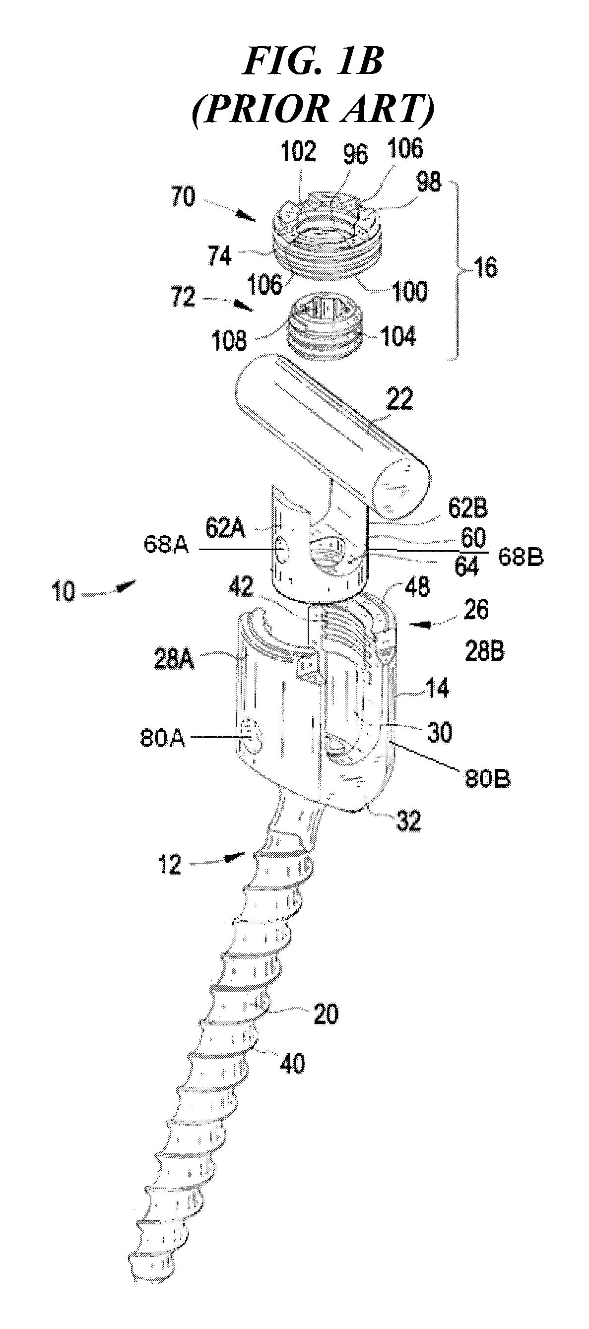
FIG. 1B is an exploded view of the bone anchor assembly of FIG. 1A;
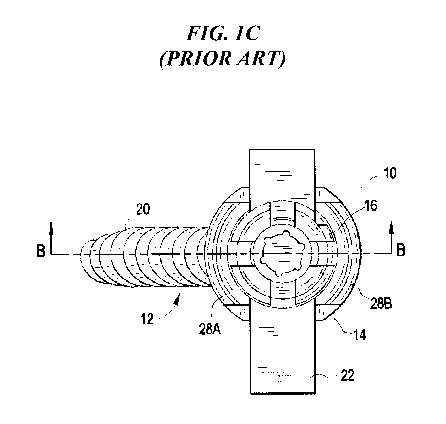
FIG. 1C is a top view of the bone anchor assembly of FIG. 1A;
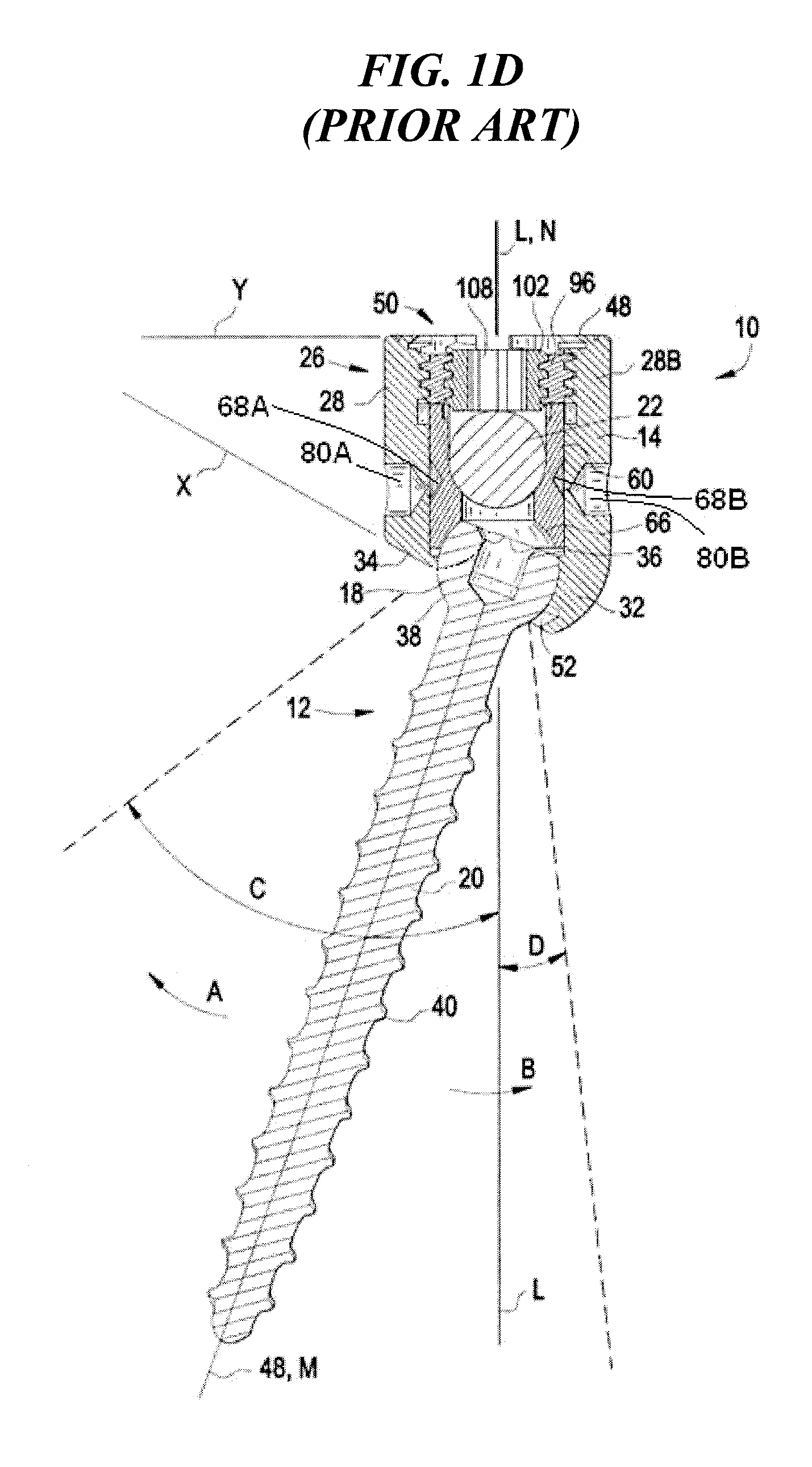
FIG. 1D is a cross-sectional view of the bone anchor assembly of FIG. 1A;
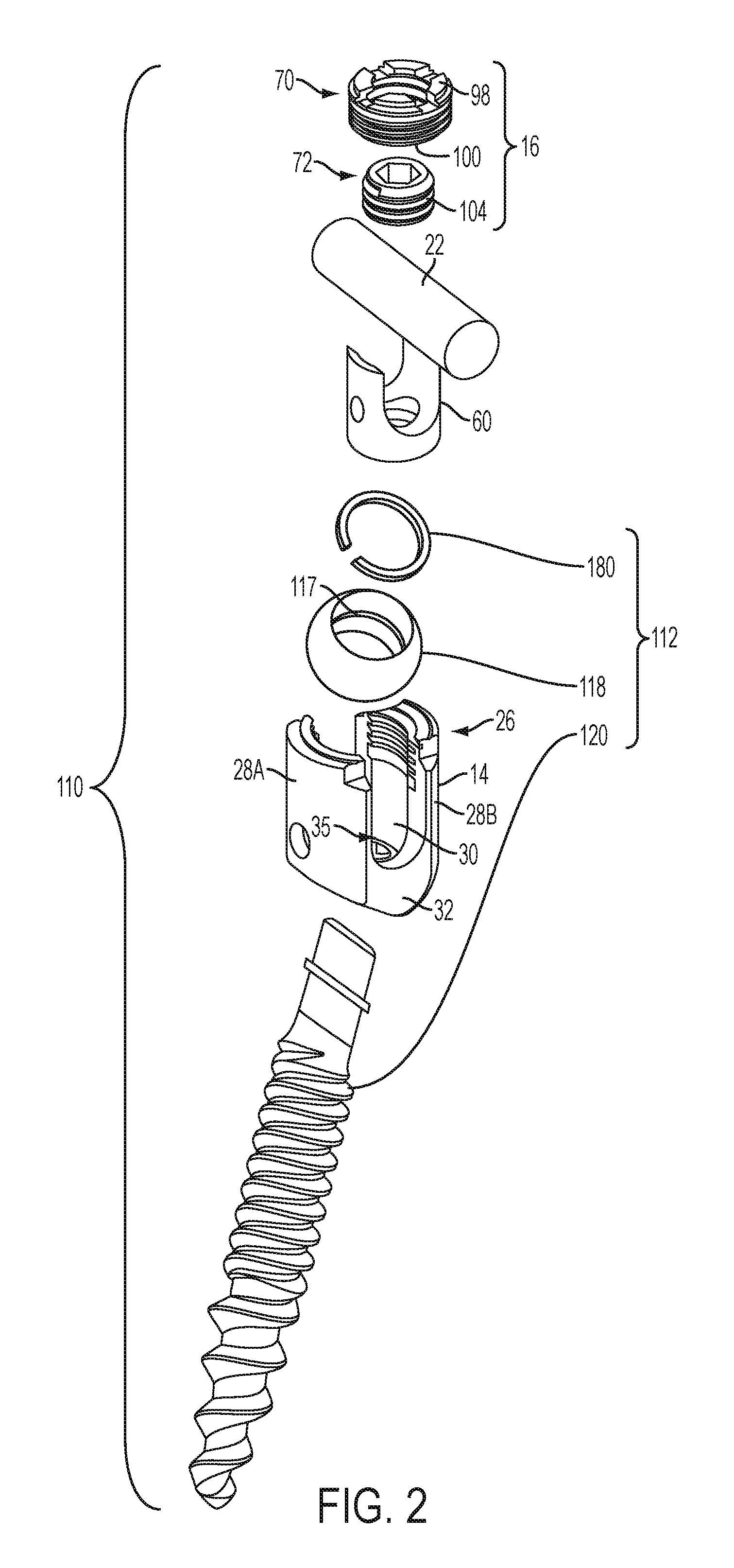
FIG. 2 is an exploded view of a bone anchor assembly including a multi-part bone anchor;
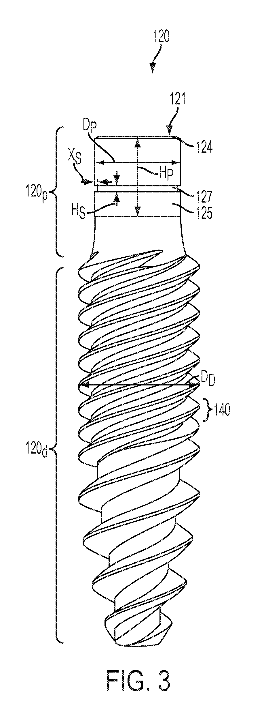
FIG. 3 is a side view of a shank of the bone anchor of FIG. 2;
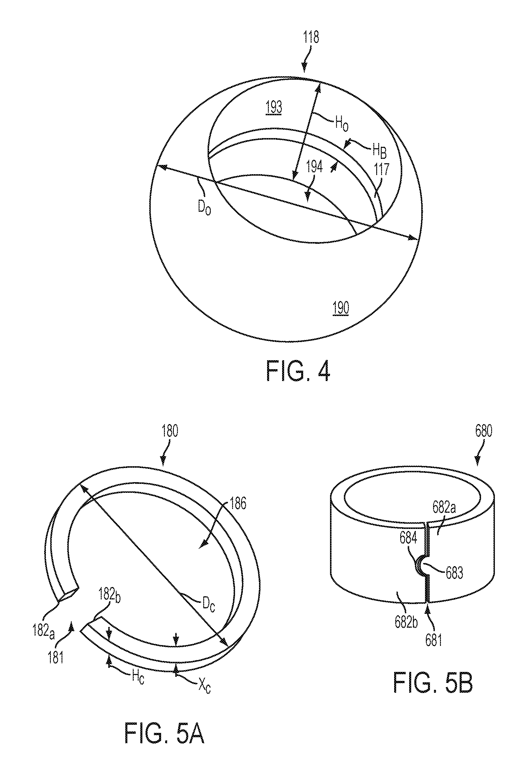
FIG. 4 is a perspective view of a ball of the bone anchor of FIG. 2;
FIG. 5A is a perspective view of a clip of the bone anchor of FIG. 2;
FIG. 5B is a perspective view of another embodiment of a clip;
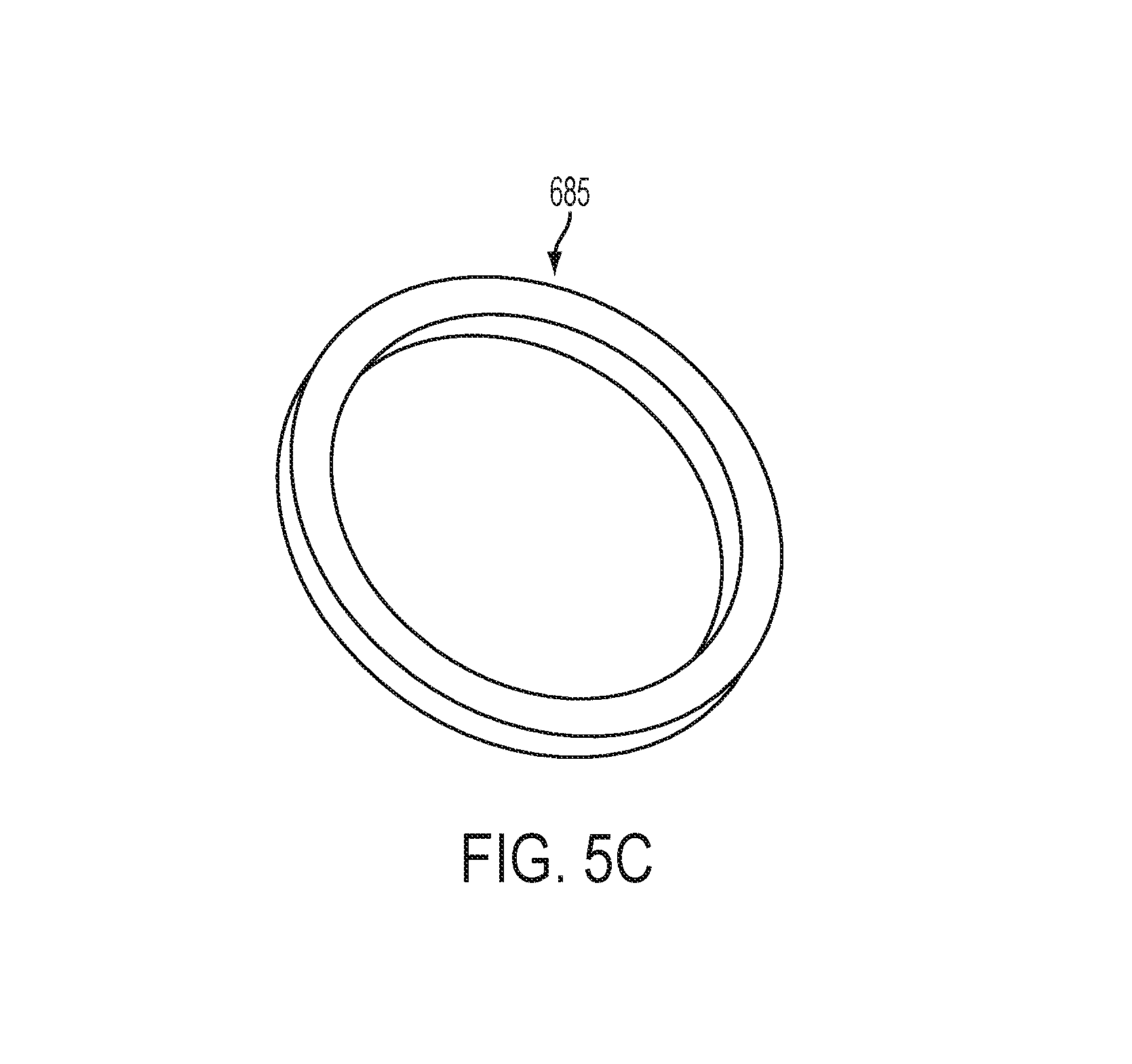
FIG. 5C is a perspective view of another embodiment of a clip;
FIG. 6A is a side view of the multi-part bone anchor of FIG. 2 shown fully assembled;
FIG. 6B is a perspective view of the clip of FIG. 5A engaged with the shank of FIG. 3; and
FIG. 6C is a perspective view of the clip of FIG. 5A engaged with the ball of FIG. 4;
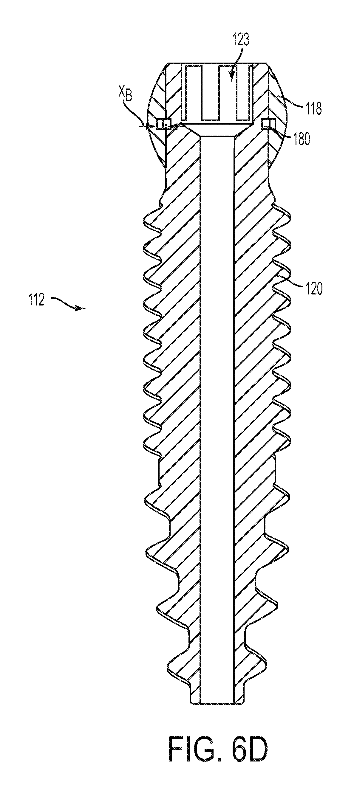
FIG. 6D is a cross-sectional view of the bone anchor of FIG. 6A; and
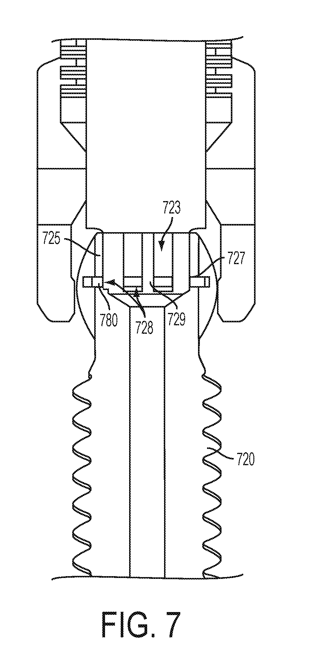
FIG. 7 is a cross-sectional view of another embodiment of a bone anchor.
DETAILED DESCRIPTION
Certain exemplary embodiments will now be described to provide an overall understanding of the principles of the structure, function, manufacture, and use of the devices and methods disclosed herein. One or more examples of these embodiments are illustrated in the accompanying drawings. Those skilled in the art will understand that the devices and methods specifically described herein and illustrated in the accompanying drawings are non-limiting exemplary embodiments and that the scope of the present invention is defined solely by the claims. The features illustrated or described in connection with one exemplary embodiment may be combined with the features of other embodiments. Such modifications and variations are intended to be included within the scope of the present invention.
In general, various bone anchor assemblies and methods are provided having a multi-component bone anchor that is configured to allow the shank of the bone anchor to be bottom-loaded into a receiver member before or during a procedure. Such devices and methods can allow for the use of bone anchors having large diameter shanks capable of withstanding greater bending forces, while still utilizing a relatively low-profile receiver member for coupling a spinal fixation element to the bone anchor. The bone anchor assemblies and methods can also be particularly useful with favored-angle bone anchors in which a cone of angulation of the bone anchor relative to the receiver member is biased in one direction.
FIGS. 1A-1D illustrate a prior art bone anchor assembly 10 including a bone anchor 12, a receiver member 14 for receiving a spinal fixation element, such as a spinal rod 22, to be coupled to the bone anchor 12, and a closure mechanism 16 to capture a spinal fixation element within the receiver member 14 and fix the spinal fixation element with respect to the receiver member 14. The bone anchor 12 includes a proximal head 18 and a distal shaft 20 configured to engage bone. The receiver member 14 has a proximal end 26 having a pair of spaced apart arms 28A, 28B defining a recess 30 therebetween and a distal end 32 having a distal end surface 34 defining an opening through which at least a portion of the bone anchor 12 extends. The closure mechanism 16 can be positionable between and can engage the arms 28A, 28B to capture a spinal fixation element, e.g., a spinal rod 22, within the receiver member 14 and fix the spinal fixation element with respect to the receiver member 14.
The proximal head 18 of the bone anchor 12 is generally in the shape of a truncated sphere having a planar proximal surface 36 and an approximately spherically-shaped distal surface 38. The illustrated bone anchor assembly is a polyaxial bone screw designed for posterior implantation in the pedicle or lateral mass of a vertebra. The proximal head 18 of the bone anchor 12 engages the distal end 32 of the receiver member 14 in a ball and socket like arrangement in which the proximal head 18 the distal shaft 20 can pivot relative to the receiver member 14, i.e., the distal end 32 defines a polyaxial seat on a proximal surface thereof for the bone anchor 12. The distal surface 38 of the proximal head 18 of the bone anchor 12 and a mating surface within the distal end 32 of the receiver member 14 can have any shape that facilitates this arrangement, including, for example, spherical (as illustrated), toroidal, conical, frustoconical, and any combinations of these shapes.
The distal shaft 20 of the bone anchor 12 can be configured to engage bone and, in the illustrated embodiment, includes an external bone engaging thread 40. The thread form for the distal shaft 20, including the number of threads, the pitch, the major and minor diameters, and the thread shape, can be selected to facilitate connection with bone. Exemplary thread forms are disclosed in U.S. Patent Application Publication No. 2011/0288599, filed on May 18, 2011, and in U.S. Provisional Patent Application Ser. No. 61/527,389, filed Aug. 25, 2011, both of which are incorporated herein by reference. The distal shaft 20 can also include other structures for engaging bone, including a hook. The distal shaft 20 of the bone anchor 12 can be cannulated, having a central passage or cannula extending the length of the bone anchor to facilitate delivery of the bone anchor over a guide wire in, for example, minimally-invasive procedures. Other components of the bone anchor assembly, including, for example, the closure member 16, the receiver member 14, and the compression member 60 (discussed below) can be cannulated or otherwise have an opening to permit delivery over a guide wire. The distal shaft 20 can also include one or more sidewall openings or fenestrations that communicate with the cannula to permit bone in-growth or to permit the dispensing of bone cement or other materials through the bone anchor 12. The sidewall openings can extend radially from the cannula through the sidewall of the distal shaft 20. Exemplary systems for delivering bone cement to the bone anchor assembly 10 and alternative bone anchor configurations for facilitating cement delivery are described in U.S. Patent Application Publication No. 2010/0114174, filed on Oct. 29, 2009, which is hereby incorporated herein by reference. The distal shaft 20 of the bone anchor 12 can also be coated with materials to permit bone growth, such as, for example, hydroxyapatite, and the bone anchor assembly 10 can be coated partially or entirely with anti-infective materials, such as, for example, tryclosan.
The proximal end 26 of the receiver member 14 includes a pair of spaced apart arms 28A, 28B defining a U-shaped recess 30 therebetween for receiving a spinal fixation element, e.g., a spinal rod 22. Each of the arms 28A, 28B can extend from the distal end 32 of the receiver member 14 to a free end. The outer surfaces of each of the arms 28A, 28B can include a feature, such as a recess, dimple, notch, projection, or the like, to facilitate connection of the receiver member 14 to instruments. For example, the outer surface of each arm 28A, 28B can include an arcuate groove at the respective free end of the arms. Such grooves are described in more detail in U.S. Pat. No. 7,179,261, issued on Feb. 20, 2007, which is hereby incorporated herein by reference. At least a portion of the proximal end surface 48 of the receiver member 12 defines a plane Y. The receiver member 14 has a central longitudinal axis L.
The distal end 32 of the receiver member 14 includes a distal end surface 34 which is generally annular in shape defining a circular opening through which at least a portion of the bone anchor 12 extends. For example, the distal shaft 20 of the bone anchor 12 can extend through the opening. At least a portion of the distal end surface 34 defines a plane X.
The bone anchor 12 can be selectively fixed relative to the receiver member 14. Prior to fixation, the bone anchor 12 is movable relative to the receiver member 14 within a cone of angulation generally defined by the geometry of the distal end 32 of the receiver member and the proximal head 18 of the bone anchor 12. The illustrated bone anchor is a favored-angle polyaxial screw in which the cone of angulation is biased in one direction. In this manner, the bone anchor 12 is movable relative to the receiver member 14 in at least a first direction, indicated by arrow A in FIG. 1D, at a first angle C relative to the central longitudinal axis L of the receiver member 14. The bone anchor 12 is also movable in at least a second direction, indicated by arrow B in FIG. 1D, at a second angle D relative to the longitudinal axis L. The first angle C is greater than the second angle D and, thus, the shaft 20 of the bone anchor 12 is movable more in the direction indicated by arrow A than in the direction indicated by arrow B. The distal shaft 20 of the bone anchor 12 defines a neutral axis 48 with respect to the receiver member 14. The neutral axis 48 can be perpendicular to the plane X defined by the distal end surface 34 and intersects the center point of the opening in the distal end surface 34 through which the distal shaft 20 of the bone anchor 12 extends. The neutral axis 48 can be oriented at an angle to the central longitudinal axis L of the receiver member 14. The plane Y defined by at least a portion of the proximal end surface 48 of the receiver member 14 intersects the plane X defined by at least a portion of the distal end surface 34 of the receiver member 12. The proximal end 26 of the receiver member 14 can include a proximal first bore 50 coaxial with a first central longitudinal axis N (which is coincident with longitudinal axis L) and a distal second bore 52 coaxial with a second central longitudinal axis M (which is coincident with the neutral axis 48) and the first central longitudinal axis N and second central longitudinal axis M can intersect one another. The angle between the plane X and the plane Y and the angle between the axis L and the axis M can be selected to provide the desired degree of biased angulation. Examples of favored angled polyaxial screws are described in more detail in U.S. Pat. No. 6,974,460, issued on Dec. 13, 2005, and in U.S. Pat. No. 6,736,820, issued on May 18, 2004, both of which are hereby incorporated herein by reference. Alternatively, the bone anchor assembly can be a conventional (non-biased) polyaxial screw in which the bone anchor pivots in the same amount in every direction and has a neutral axis that is coincident with the central longitudinal axis L of the receiver member.
The spinal fixation element, e.g., the spinal rod 22, can either directly contact the proximal head 18 of the bone anchor 12 or can contact an intermediate element, e.g., a compression member 60. The compression member 60 can be positioned within the receiver member 14 and interposed between the spinal rod 22 and the proximal head 18 of the bone anchor 12 to compress the distal outer surface 38 of the proximal head 18 into direct, fixed engagement with the distal inner surface of the receiver member 14. The compression member 60 can include a pair of spaced apart arms 62A and 62B defining a U-shaped seat 64 for receiving the spinal rod 22 and a distal surface 66 for engaging the proximal head 18 of the bone anchor 12.
The proximal end 26 of the receiver member 14 can be configured to receive a closure mechanism 16 positionable between and engaging the arms 28A, 28B of the receiver member 14. The closure mechanism 16 can be configured to capture a spinal fixation element, e.g., a spinal rod 22, within the receiver member 14, to fix the spinal rod 22 relative to the receiver member 14, and to fix the bone anchor 12 relative to the receiver member 14. The closure mechanism 16 can be a single set screw having an outer thread for engaging an inner thread 42 provided on the arms 28A, 28B of the receiver member 14. In the illustrated embodiment, however, the closure mechanism 16 comprises an outer set screw 70 positionable between and engaging the arms 28A, 28B of the receiver member 14 and an inner set screw 72 positionable within the outer set screw 70. The outer set screw 70 is operable to act on the compression member 60 to fix the bone anchor 12 relative to the receiver member 14. The inner set screw 72 is operable to act on the spinal rod 22 to fix the spinal rod 22 relative to the receiver member 14. In this manner, the closure mechanism 16 permits the bone anchor 12 to be fixed relative to the receiver member 14 independently of the spinal rod 22 being fixed to the receiver member 14. In particular, the outer set screw 70 can engage the proximal end surfaces of the arms 62A, 62B of the compression member 60 to force the distal surface 66 of the compression member 60 into contact with the proximal head 18 of bone anchor 12, which in turn forces the distal surface 38 of the proximal head 18 into fixed engagement with the distal inner surface of the receiver member 14. The inner set screw 72 can engage the spinal rod 22 to force the spinal rod 22 into fixed engagement with the rod seat 64 of the compression member 60.
The outer set screw 70 includes a first outer thread 74 for engaging a complementary inner thread 42 on the arms 28A, 28B of the receiver member 14. The outer set screw 74 includes a central passage 96 from a top surface 98 of the outer set screw 74 to a bottom surface 100 of the outer set screw 74 for receiving the inner set screw 72. The central passage 96 can includes an inner thread 102 for engaging a complementary outer thread 104 on the inner set screw 72. The thread form for the inner thread 102 and the outer thread 104, including the number of threads, the pitch, major and minor diameter, and thread shape, can be selected to facilitate connection between the components and transfer of the desired axial tightening force. The top surface 98 of the outer set screw 74 can have one or more drive features to facilitate rotation and advancement of the outer set screw 74 relative to the receiver member 14. The illustrated outer set screw 74 includes drive features in the form of a plurality of cut-outs 106 spaced-apart about the perimeter of the top surface 98. The inner set screw 104 can include drive features for receiving an instrument to rotate and advance the inner set screw 72 relative to the outer set screw 74. The illustrated inner set screw 104 includes drive features in the form of a central passage 108 having a plurality of spaced apart, longitudinally oriented cut-outs for engaging complementary features on an instrument.
The bone anchor assembly 10 can be used with a spinal fixation element such as rigid spinal rod 22. The various components of the bone anchor assemblies disclosed herein, as well as the spinal rod 22, can be constructed from various materials, including titanium, titanium alloys, stainless steel, cobalt chrome, PEEK, or other materials suitable for rigid fixation. In other embodiments, the spinal fixation element can be a dynamic stabilization member that allows controlled mobility between the instrumented vertebrae.
In use, bone can be prepared to receive the bone anchor assembly 10, generally by drilling a hole in the bone which is sized appropriately to receive the bone anchor 12. If not already completed, the bone anchor assembly 10 can be assembled, which can include assembling the bone anchor 12 and the receiver member 14, so that the distal shaft 20 extends through the opening in the distal end 32 of the receiver member 14 and the proximal head 18 of the bone anchor 12 is received in the distal end 32 of the receiver member 14. A driver tool can be fitted with the bone anchor 12 to drive the bone anchor 12 into the prepared hole in the bone. The compression member 60 can be positioned within the receiver member 14 such that the arms 62A, 62B of the compression member are aligned with the arms 28A, 28B of the receiver member 14 and the lower surface of the compression member 14 is in contact with the proximal head 18 of the bone anchor 12. A spinal fixation element, e.g., the spinal rod 22, can be located in the recess 30 of the receiver member 14. The closure mechanism 16 can be engaged with the inner thread 42 provided on the arms 28A, 28B of the receiver member 14. A torsional force can be applied to the outer set screw 70 to move it within the recess 30 using a tool which can engage the plurality of cut-outs 106 in the upper facing surface of the outer set screw 70, so as to force the compression member 60 onto the proximal head 18 of the bone anchor 12. Torsional forces can then be applied to the inner set screw 72 to move it relative to the outer set screw 70 so that it contacts the spinal rod 22 and can, for example, fix the spinal rod 22 relative to the receiver member 14 and the bone anchor 12.
One or more embodiments of inventive bone anchor assemblies are described below. Except as indicated below, the structure, operation, and use of these embodiments is similar or identical to that of the bone anchor assembly 10 described above. Accordingly, a detailed description of said structure, operation, and use is omitted here for the sake of brevity.
FIG. 2 illustrates a bone anchor assembly 110 that is similar to the bone anchor assembly 10 shown in FIGS. 1A and 1B, except that the bone anchor assembly 110 includes a multi-component bone anchor. As shown in FIG. 2, the bone anchor includes a shank 120 configured to engage bone, a spherical head or ball 118, and a clip 180 configured to be engaged between and to mate the ball 118 to the shank 120 in an assembled configuration. During manufacturing or during a surgical procedure, either before or after the shank 120 is implanted, the shank 120 can be proximally advanced, e.g., bottom-loaded, into the receiver member 14 and then mated to the ball 118 by the clip 180. The ball 180 can be polyaxially seated within a polyaxial seat in the receiver member 14 in a ball and socket like arrangement such that the ball 118 and the shank 120 can pivot relative to the receiver member 14. The clip 180 will lock the ball 118 to the shank 120 such that the shank 120 is mated to the receiver member 14. The shank 120 can be polyaxially moved relative to the receiver member 14, and once in a desired position a closure mechanism can be applied to the receiver member to lock a spinal fixation element, such as a spinal rod, therein and to also lock the receiver member 14 in a fixed position relative to the shank 120.
The shank 120 is illustrated in more detail in FIG. 3, and as shown the elongate shank 120 includes a proximal head portion 120p and a distal portion 120d. In this embodiment, the distal bone-engaging portion 120d is in the form of a threaded shank having an external bone engaging thread 140, while the proximal portion 120p is thread-free and is in the form of a head. While the proximal portion 120p can have various shapes and sizes, in an exemplary embodiment, the proximal portion 120p is generally cylindrical and has a major diameter D.sub.P that is less than a major diameter D.sub.D of the distal portion 120d. The major diameter D.sub.P of the proximal head portion 120p of the shank 120 can be less than a diameter D.sub.R (not shown) of an opening or aperture 35 in a distal end 32 of the receiver member 14 such that the proximal head portion 120p can be received through the aperture 35. Conversely, the distal portion 120d of the shank 120 can have a major diameter D.sub.D that is greater than the diameter D.sub.R (not shown) of the aperture 35 in the distal end 32 of the receiver member 14 such that the distal portion 120d of the shank 120 is prevented from passing through the aperture 35. Such a configuration can allow the proximal portion 120p of the shank 120 to be proximally advanced through the aperture 35 in the distal end 32 of the receiver member 14, i.e., "bottom-loaded" into the receiver member 14. A person skilled in the art will appreciate, however, that the shank 120 need not have a major diameter D.sub.D that is greater than the diameter of the aperture 35 in receiver member 14, and any sized shank can be used with the present invention. As further shown in FIG. 3, the proximal portion 120p of the shank 120 can also have a substantially planar proximal surface 121 that can optionally include a tool receiving recess therein (see FIG. 6B).
As indicated above, the proximal head portion 120p of the shank 120 is configured to mate with the clip 180, which also mates to the ball 118 to thereby lock the ball 118 onto the proximal head portion 120p of the shank 120. While various features can be used to mate the clip to the head portion 120p, as shown in FIG. 3, a substantially cylindrical sidewall 125 of the proximal head portion 120p can include a first annular groove 127 formed therein to receive the clip 180. As discussed further below, in one embodiment the annular groove 127 and the clip 180 can be configured to prevent axial translation of the clip 180 with respect to the shank 120 when mated together. The groove can have a variety of configurations, but in an exemplary embodiment, the annular groove 127 is formed around the entire circumference of the shank 120 and has a constant depth X.sub.S and a constant height H.sub.S. In other embodiments, as discussed below, the groove can be formed around a partial circumference of shank and/or can have varying dimensions. The location of the annular groove 127 can also vary, but it is preferably disposed at a location along the proximal head portion 120p of the shank that is configured to retain the ball 118 in a position such as that shown in FIG. 6A. In an exemplary embodiment, the annular groove 127 is located at an intermediate position between proximal and distal ends of the proximal head portion 120p.
As indicated above, the annular groove formed in the shank can have various configurations. For example, FIG. 7 shows another embodiment of a shank 720 that includes a groove 727 that intersects a tool receiving recess or driving interface 723. A clip 780 engaged in the groove 727 can bear against an instrument, e.g., a driving tool, in the driving interface 723 such that the shank 720 is mated to and retained on the instrument. The groove 727 can include a first portion 728 that intersects the driving interface 723 and that is configured to allow the clip 780 to bear against a tool within the driving interface. The first portion 728 can be in the form of opposed cut-outs or openings extending through the sidewall 725 of the shank (compare with FIG. 6D, in which the clip 180 does not penetrate the tool receiving recess 123). The groove 727 can also include a second portion 729 that does not penetrate the sidewall 725 of the shank 720 and that is configured to retain the clip 780 outside of the driving interface 723. The second portion 729 can likewise be formed in opposed sidewalls of the shank 720.
Returning to the embodiment of FIG. 3, the proximal head portion 120p of the shank can include various other features. For example, the head portion 120p can be configured to facilitate mating with the clip 180. As shown, the head portion 120p can include a tapered lead portion at a proximal end thereof that is configured to gradually expand the clip 180 as the clip 180 is advanced distally onto the shank 120. In an exemplary embodiment, the tapered lead portion is a substantially spherical surface 124 that extends between the proximal surface 121 and the cylindrical sidewall 125 on the proximal head portion 120p. It will be understood, however, that the tapered lead portion can have various configurations and can be either formed on the proximal head portion 120p, as shown in FIG. 3, or can be separate therefrom. For example, the tapered lead portion can be a separate member or blank (not shown) sized and shaped like the spherical surface 124 and configured to reversibly mate to the proximal head portion 120p of the shank 120 such that a clip 180 can be expanded when advanced distally on the blank and, when the blank is mated with the proximal portion 120p of the shank 120, the clip 180 can be further advanced directly onto the proximal portion 120p of the shank and the blank can be removed from the shank 120. The blank can be mated to the shank 120 using various techniques, such as threads, a twist-lock, snap-fit, pressure fit, or other mechanical engagement mechanisms.
The ball 118 of the bone anchor is shown in more detail in FIG. 4, and is configured to receive the proximal head portion 120p of the shank 120 therein with the clip 180 engaged there between. While the ball 118 can have various configurations, in an exemplary embodiment, the ball 118 is at least partially spherical to allow the ball 118 to be seated within a spherical recess in the receiver member 14 to form a ball and socket like arrangement that allows the shank 120 to pivot relative to the receiver member 14. As shown in FIG. 4, the ball 118 can be a truncated sphere with a substantially spherical exterior surface 190. While the spherical exterior surface 190 can provide for a full range of polyaxial motion, in other embodiments, the spherical outer surface 190 can include one or more flat portions (not shown) that correspond to flat portions of the receiver member 14 such that angulation of the bone anchor is limited to a single plane. When mated with the ball 118, in some embodiments, the spherical surface 124 of the shank and the spherical exterior surface 190 of the ball 118 can form a substantially continuous spherical surface (see FIG. 6A). However, in other embodiments, the spherical surface 124 of the shank 120 and the spherical exterior surface 190 of the ball 118 can share a common center point and can form an interrupted spherical surface.
The dimensions of the ball can also vary, but in an exemplary embodiment, the ball 118 can have a diameter D.sub.O that is greater than the diameter D.sub.R (not shown) of the aperture 35 in the distal end 32 of the receiver member 14 such that the ball 118 is prevented from passing through the aperture 35. The ball 118 can have a height Ho that is less than or equal to a height H.sub.P of the proximal head portion 120p of the shank 120. In the illustrated embodiment, the ball 118 is rigid and inflexible. For example, the ball 118 can be non-expandable so as to prevent the outer ring from deforming and detaching from the shank 120 when the bone anchor is coupled to the receiver member 14. In particular, the ball 118 can be solid with an unbroken circumference, having no slits or cuts formed therein such that it does not bend, compress, or expand.
As further shown in FIG. 4, the ball 118 can include an inner surface 193 that defines a lumen or bore 194 extending therethrough that is configured to receive the proximal portion 120p of the shank 120. In an exemplary embodiment, the bore 194 is cylindrical to correspond with the proximal head portion 120p of the shank 120 (see FIG. 6D), however, it will be understood that the bore can have various other shapes, such as hourglass or frustoconical, for example.
In order to facilitate mating engagement between the ball 118 and the clip 180, the inner surface 193 of the bore 194 of the ball 118 can include a second annular groove 117 formed therein for seating at least a portion of the clip 180. Similar to the first annular groove 127, the second annular groove can have a variety of configurations, but in an exemplary embodiment, the annular groove 117 is formed around the entire circumference of the bore 194 and has a constant depth (not shown) and a constant height H.sub.B. In other embodiments, as discussed below, the groove 117 can be formed around a partial circumference of bore in the ball 118 and/or can have varying dimensions. The location of the annular groove 117 can also vary, but it is preferably disposed at a location along the length of the bore that is configured to retain the ball 118 on the shank 120 in a position such as that shown in FIG. 6A. In an exemplary embodiment, the annular groove 117 is located at an intermediate position between proximal and distal ends of the bore 194 in the ball 118.
The clip 180 is illustrated in more detail in FIG. 5A and can generally be circular or cylindrical. The clip 180 can be configured to be partially seated within the first annular groove 127 of the shank 120 and partially seated within the second annular groove 117 of the ball 118 to mate the shank 120 with the ball 118. In an exemplary embodiment, the clip 180 is C-shaped with a radial slit 181 for allowing a diameter D.sub.C of the clip to be adjusted. The clip 180 can have a height H.sub.C that is less than or equal to a height H.sub.S of the first annular groove 127 and less than or equal to a height H.sub.B of the second annular groove 117. In an exemplary embodiment, the height H.sub.C of the clip is substantially equal to each of the height H.sub.S of the first annular groove 127 and the height H.sub.B of the second annular groove 117 such that, when the clip 180 is partially seated within the first and second annular grooves 127, 117 to mate the shank 120 and the ball 118, the ball 118 and the shank 120 are prevented from translating axially relative to one another. The clip 180 can also have a width X.sub.C that is less than each of a depth X.sub.S of the first annular groove 127 and a depth X.sub.B of the second annular groove 117, and that is equal to or less than a combined depth X.sub.S of the first annular groove 127 and depth X.sub.B of the second annular groove such that the clip 180 can be entirely recessed within both grooves. In an exemplary embodiment, the clip 180 has a width X.sub.C that is less than the combined depth X.sub.S of the first annular groove 127 and depth X.sub.B of the second annular groove 117 so as to allow the clip 180 to expand or contract into one of the grooves 117, 127 as the shank and ball are advanced relative to one another. While FIG. 5A illustrates a C-shaped clip, it will be understood that the clip can have various other configurations, such as an E-clip, a K-type clip, a wire, band, tube, or ring without a slit, as discussed further below, etc.
As indicated above, the slit 181 in the clip 180 can allow the clip to expand and contract such that a maximum diameter D.sub.C of the clip 180 is adjustable, i.e., can increase or decrease. For example, the maximum diameter D.sub.C can increase when the proximal head portion 120p of the shank 120 is being advanced through a lumen 186 of the clip 180, or the diameter D.sub.C can decrease when the clip 180 is being advanced through the lumen 194 of the ball 118. The slit can have a variety of configurations. For example, as shown in FIG. 5A, the slit 181 can be in the form of a radial cut extending longitudinally through the clip 180 from an outer surface 187 to an inner surface 188 thereof. In an exemplary embodiment, the slit 181 defines straight opposed first and second sides 182a, 182b. In other embodiments, the slit can be non-linear, interlocking or non-interlocking. For example, FIG. 5B, shows another embodiment of a clip 680 that has a non-linear slit 681 that defines a first side 682a with a tab 683 formed thereon and a second side 682b with a complementary recess 684 formed therein such that the tab 683 and the recess 684 are configured to interlock the first and second sides 682a, 682b. The slit can vary in size and a distance between first and second sides 182a, 182b of the slit can increase or decrease as the ring 180 expands or contracts.
As indicated above, in another embodiment, the clip can be slit-free while still being flexible to allow the diameter to increase and decrease. By way of example, FIG. 5C illustrates a clip 685 in the form of a continuous ring or band having an uninterrupted circumference, i.e., without a slit, that can expand and contract. The clip can be formed from an expandable material such that a maximum diameter of the clip can increase and/or decrease when a force is applied thereto. Exemplary materials include, by way of non-limiting example, shape memory alloys, such as nitinol, and any material that has elastic properties. In another aspect, the clip can heated and/or cooled such that a maximum diameter of the clip can be adjusted.
In use, the bone anchor assembly 110 can be assembled during manufacturing, before surgery, or intraoperatively. FIGS. 6A and 6D show an exemplary assembled bone anchor. While the method is shown in connection with the bone anchor assembly of FIG. 2, the method can be used with any of the bone anchor assemblies disclosed herein. The proximal portion 120p of the shank 120 can be proximally advanced through the aperture 35 in the distal end 32 of the receiver member 14, i.e., bottom-loaded into the receiver member 14, and the ball 118 can be top-loaded into the receiver member 14 thereafter. The clip 180 can initially be seated in one of the annular groove 127 in the shank 120 (as shown in FIG. 6B) and the annular groove 117 in the ball (as shown in FIG. 6C).
In one embodiment, the clip 180 can be initially seated in the annular groove 127 in the shank 120. In this embodiment, the clip 180 can have a width X.sub.C that is equal to a depth X.sub.S of the first annular groove 127. During assembly, the diameter D.sub.C of the clip 180 can be expanded, e.g., increased, to receive the proximal head portion 120p of the shank 120 within the lumen 186 thereof. For example, the clip 180 can be expanded over a tapered lead, e.g., a spherical surface 124 formed at a proximal end of the proximal head portion 120p of the shaft 120 or, alternatively, the clip 180 can be expanded over a tapered blank, which can then be displaced by the proximal head portion 120p of the shank 120 when the clip 180 is sufficiently expanded. Once the clip 180 is aligned with the groove 127, the clip can return to its original state to be seated within the annular groove 127. As the proximal head portion 120p of the shank 120 is advanced through the bore 194 of the ball 118, the depth X.sub.S of the first annular groove 127 can allow the clip to compress and be fully received within the annular groove 127. Once the first annular groove 127 is aligned with the second annular groove 117 in the ball 118, the clip 180 can once again return to its original state such that the clip 180 extends partially into each groove 117, 127.
In another embodiment, the clip 180 can be initially seated in the annular groove 117 in the ball 118. In this embodiment, the clip 180 can have a width X.sub.C that is equal to a depth X.sub.B of the second annular groove 117. During assembly, the diameter D.sub.C of the clip 180 can be compressed, e.g., decreased, as the clip 180 is advanced through the lumen 194 of the ball 118. Once the clip 180 is aligned with the groove 117, the clip can return to its original state to be seated within the annular groove 117. As the proximal head portion 120p of the shank 120 is advanced through the bore 194 of the ball 118, the depth X.sub.B of the second annular groove 117 can allow the clip to expand and be fully received within the annular groove 117. Once the first annular groove 127 is aligned with the second annular groove 117 in the ball 118, the clip 180 can once again return to its original state such that the clip 180 extends partially into each groove 117, 127.
With the grooves 117, 127 are aligned and the clip 180 extending into each of the grooves 117, 127, the shank 120 and the ball 118 will be locked a substantially fixed relationship relative to each other, as shown in FIG. 6D. Since the ball 118 is sized to prevent passage through the aperture 35 of the receiver member 14, the proximal portion 120p of the shank 120 is maintained within the receiver member 14. The multi-component bone anchor thus allows for assembly using a bottom loading technique. This can be particularly advantageous with large diameter shanks that are not sized to be distally advanced through the proximal end of the receiver and through the aperture in the receiver member. The secure mating connection between the components also allows the ball 118 to be sized so as to prevent passage through the aperture 35 in the receiver member 14, even when the shank 120 is fully angled to the maximum angulation allowed for the illustrated favored-angle bone anchor assembly.
The bone anchor 120 can be implanted in bone, either before or after coupling the receiver member 14 to the shank 120, using a driver tool fitted with the bone anchor. In some embodiments, as discussed with respect to FIGS. 7A and 7B, the clip 180 can intersect the driving interface 723 and can bear against the driver tool to retain shank on the driving tool. A compression member, if utilized, can be positioned within the receiver member 14 such that the arms 62A, 62B of the compression member 60 are aligned with the arms 28A, 28B of the receiver member 14 and the distal-facing surface of the compression member 60 is in contact with the bone anchor. The compression member 60 can exert a frictional force on part of the bone anchor, e.g., the ball 118, to maintain the shank 120 in a desired orientation relative to the receiver member 14, while still allowing movement of the shank 120 with respect to the receiver member 14.
Once the bone anchor is implanted in bone and the receiver member 14 is attached thereto, the receiver member 14 can be pivoted or angulated relative to the bone anchor. One or more bone anchor assemblies (not shown) can also be deployed into bone using the same or different techniques. A spinal fixation element, e.g. the spinal rod 22, can be positioned in the recess 30 of the receiver member 14 and can be manipulated in various ways using various tools so that the spinal rod 22 extends through one or more bone anchor assemblies. Manipulating the spinal rod 22 can change an angle of the receiver member 14 relative to the bone anchor. When the spinal rod 22 is in a desired position, a closure mechanism 16 can be engaged with the inner thread provided on the arms 28A, 28B of the receiver member 14. The closure mechanism 16 can fix the spinal rod 22 relative to the bone anchor assembly 110, and also cause the compression member 60 to engage the part of the bone anchor, e.g., the ball 118, to lock the receiver member 14 in a fixed position relative to the shank 120.
Although the invention has been described by reference to specific embodiments, it should be understood that numerous changes may be made within the spirit and scope of the inventive concepts described. Accordingly, it is intended that the invention not be limited to the described embodiments, but that it have the full scope defined by the language of the following claims.
* * * * *
References
D00000
D00001
D00002
D00003
D00004
D00005
D00006
D00007
D00008
D00009
D00010
D00011
D00012
XML
uspto.report is an independent third-party trademark research tool that is not affiliated, endorsed, or sponsored by the United States Patent and Trademark Office (USPTO) or any other governmental organization. The information provided by uspto.report is based on publicly available data at the time of writing and is intended for informational purposes only.
While we strive to provide accurate and up-to-date information, we do not guarantee the accuracy, completeness, reliability, or suitability of the information displayed on this site. The use of this site is at your own risk. Any reliance you place on such information is therefore strictly at your own risk.
All official trademark data, including owner information, should be verified by visiting the official USPTO website at www.uspto.gov. This site is not intended to replace professional legal advice and should not be used as a substitute for consulting with a legal professional who is knowledgeable about trademark law.