Rotary compressor having two cylinders
Nakai , et al.
U.S. patent number 10,233,929 [Application Number 15/118,857] was granted by the patent office on 2019-03-19 for rotary compressor having two cylinders. This patent grant is currently assigned to Panasonic Intellectual Property Management Co., Ltd.. The grantee listed for this patent is Panasonic Intellectual Property Management Co., Ltd.. Invention is credited to Tsuyoshi Karino, Hiroaki Nakai, Shingo Oyagi, Yu Shiotani, Hirofumi Yoshida.


| United States Patent | 10,233,929 |
| Nakai , et al. | March 19, 2019 |
Rotary compressor having two cylinders
Abstract
A rotary compressor having two cylinders includes crankshaft having first eccentric portion and second eccentric portion connected to each other by connecting portion. The rotary compressor further includes two compressive elements that compress working fluid in cylinder as first piston inserted over first eccentric portion eccentrically rotates in accordance with rotation of crankshaft. Further, first piston inserted over first eccentric portion undergoes assembly by being inserted over first eccentric portion through second eccentric portion. Further, a releasing portion is provided at each of outer diameter portions of first eccentric portion and second eccentric portion.
| Inventors: | Nakai; Hiroaki (Shiga, JP), Yoshida; Hirofumi (Shiga, JP), Oyagi; Shingo (Osaka, JP), Shiotani; Yu (Osaka, JP), Karino; Tsuyoshi (Shiga, JP) | ||||||||||
|---|---|---|---|---|---|---|---|---|---|---|---|
| Applicant: |
|
||||||||||
| Assignee: | Panasonic Intellectual Property
Management Co., Ltd. (Osaka, JP) |
||||||||||
| Family ID: | 54937650 | ||||||||||
| Appl. No.: | 15/118,857 | ||||||||||
| Filed: | June 8, 2015 | ||||||||||
| PCT Filed: | June 08, 2015 | ||||||||||
| PCT No.: | PCT/JP2015/002857 | ||||||||||
| 371(c)(1),(2),(4) Date: | August 13, 2016 | ||||||||||
| PCT Pub. No.: | WO2015/198539 | ||||||||||
| PCT Pub. Date: | December 30, 2015 |
Prior Publication Data
| Document Identifier | Publication Date | |
|---|---|---|
| US 20170167487 A1 | Jun 15, 2017 | |
Foreign Application Priority Data
| Jun 24, 2014 [JP] | 2014-128742 | |||
| Current U.S. Class: | 1/1 |
| Current CPC Class: | F04C 23/00 (20130101); F04C 18/356 (20130101); F04C 18/3564 (20130101); F04C 29/0057 (20130101); F04C 29/00 (20130101); F04C 18/44 (20130101); F04C 23/001 (20130101); F04C 2240/60 (20130101); F04C 2240/20 (20130101) |
| Current International Class: | F03C 2/00 (20060101); F04C 18/356 (20060101); F04C 23/00 (20060101); F04C 29/00 (20060101); F04C 11/00 (20060101); F03C 4/00 (20060101); F04C 18/44 (20060101) |
| Field of Search: | ;418/11,13,60,63,150 |
References Cited [Referenced By]
U.S. Patent Documents
| 2010/0147013 | June 2010 | Hirayama |
| 2012-036822 | Feb 2012 | JP | |||
| 5117503 | Jan 2013 | JP | |||
| 2009/028633 | Mar 2009 | WO | |||
Other References
|
International Search Report of PCT application No. PCT/JP2015/002857 dated Aug. 18, 2015. cited by applicant . English Translation of Chinese Search Report dated Mar. 23, 2018 for the related Chinese Patent Application No. 201580010210.1, 2 pages. cited by applicant . The Communication pursuant to Article 94(3) EPC dated Nov. 7, 2017 for the related European Patent Application No. 15811982.6. cited by applicant. |
Primary Examiner: Trieu; Theresa
Attorney, Agent or Firm: Hamre, Schumann, Mueller & Larson, P.C.
Claims
The invention claimed is:
1. A rotary compressor having two cylinders, the compressor comprising: a crankshaft having a first eccentric portion and a second eccentric portion connected to each other by a connecting portion; and two compressive elements that compress working fluid in cylinders as a first piston inserted over the first eccentric portion eccentrically rotates in accordance with rotation of the crankshaft, wherein the first piston inserted over the first eccentric portion undergoes assembly by being inserted over the first eccentric portion through the second eccentric portion, a first releasing portion is provided at an outer diameter portion of the first eccentric portion, a second releasing portion is provided at an outer diameter portion of the second eccentric portion, the first releasing portion being positioned on a side of the outer diameter portion of the first eccentric portion close to the connecting portion, the second releasing portion being positioned on a side of the outer diameter portion of the second eccentric portion close to the connecting portion, the first and the second releasing portions being structured by step portions, each of the first and the second releasing portions being concentric to the first eccentric portion and the second eccentric portion respectively, and the first and the second releasing portions having a reduced outer diameter relative to the first eccentric portion and the second eccentric portion respectively, Hc-c<Hp-Hpc<Hc-c+Hcd<Hp is established where Hc-c is a height of the connecting portion, Hcd is a height of the first releasing portion or the second releasing portion, Hp is a height of the first piston, and Hpc is a height of one of bevels respectively provided at both surfaces of the first piston, and an outermost diameter of a projection cross section obtained by overlaying a cross section of the first eccentric portion excluding the first releasing portion and a cross section of the second eccentric portion excluding the second releasing portion on each other is set to be greater than an inner diameter of the first piston.
2. The rotary compressor according to claim 1, wherein the bevels of the first piston are each structured to be greater in an axial direction than in a radial direction.
3. The rotary compressor according to claim 1, wherein, in the first and the second releasing portions, respective eccentric sites of the first eccentric portion and the second eccentric portion are largely beveled as compared to other sites of the first eccentric portion and the second eccentric portion.
4. The rotary compressor according to claim 1, wherein the first piston is structured so as to avoid independent rotation, by being coupled or integrated with a vane that oscillates in the cylinder.
Description
This application is a U.S. national stage application of the PCT international application No. PCT/JP2015/002857 filed on Jun. 8, 2015, which claims the benefit of foreign priority of Japanese patent application No. 2014-128742 filed on Jun. 24, 2014, the contents all of which are incorporated herein by reference.
TECHNICAL FIELD
The present invention relates to a rotary compressor having two cylinders used for an air conditioner, a freezer, a blower, a water heater and the like.
BACKGROUND ART
In a freezing apparatus or an air conditioning apparatus, what is used is a compressor that suctions a gas refrigerant evaporated by an evaporator and compresses the refrigerant to a pressure required for the gas refrigerant to condense, and feeds the gas refrigerant of high temperature and high pressure into a refrigerant circuit. As such a compressor, a rotary compressor is known. Among others, a rotary compressor having two cylinders, in which two compression chambers are structured in the compressor, is actively developed as a high-performance compressor for its characteristics including low vibrations, low noises, and capability of high-speed operations. There is a demand for a compressor of higher capacity while being small in size.
Measures taken to increase the capacity of a rotary compressor include increasing the height of a cylinder thereby increasing the capacity, and increasing the amount of eccentricity of a crankshaft thereby increasing the containment capacity of a compression chamber.
In the case where the capacity is increased by increasing the height of the cylinder, the diameter of the crankshaft must be increased in order to address increased bearing loads. Thus, the efficiency of the compressor is disadvantageously reduced.
On the other hand, the case where any measures for increasing the amount of eccentricity of a crankshaft is employed for a rotary compressor having two cylinders is discussed. In general, the crankshaft of the rotary compressor having two cylinders is provided with eccentric portions at positions opposite from each other by 180.degree.. Pistons are respectively inserted over the eccentric portions. The crankshaft itself is supported by a main bearing that mainly pivotally supports the crankshaft, and an auxiliary bearing that pivotally supports the crankshaft on the opposite side relative to the eccentric portions, and is smaller in diameter than the main bearing. When the amount of eccentricity of the crankshaft is increased, the counter-eccentric direction of the eccentric portion of the crankshaft is positioned inward than the diameter of the main shaft, making it impossible for the piston to be inserted. A scheme for avoiding such a problem uses the difference in diameter between a main shaft portion and an auxiliary shaft portion of the crankshaft. In the scheme, a first piston to be inserted over a first eccentric portion on the side nearer to the main shaft portion is caused to pass through the auxiliary shaft portion, a second eccentric portion on the side nearer to the auxiliary shaft portion, and a connecting portion, to be inserted over the first eccentric portion. Here, the connecting portion connects between the first eccentric portion and the second eccentric portion.
In such a case, a highly efficient compressor can be realized without excessively increasing the diameter of the eccentric shaft. Further, the main shaft portion whose diameter is greater can support the load on the two eccentric portions by a greater amount. However, also in such a case, an increase in the amount of eccentricity reduces the diameter of the connecting portion connecting between the two eccentric portions, whereby rigidity of the crankshaft reduces at the connecting portion. This increases the load on the auxiliary bearing whose diameter is smaller, causing a reduction in reliability.
In view of such problems, there is a need for measures against a reduction in rigidity of the connecting portion, while avoiding a reduction in efficiency of the compressor such as an increase in diameter of the main shaft portion, the auxiliary shaft portion, and the eccentric portion.
Addressing the problems, for example in a rotary compressor described in PTL 1, a raised portion is provided at a connecting portion in a dimensional range capable of being accommodated in a bevel at the inner surface of a piston, to increase rigidity of the connecting portion.
With the conventional structure, in order to largely increase rigidity of the connecting portion, measures such as increasing the beveling diameter at the inner surface of the piston must be taken. However, since an increase in the bevel of the piston in the radial direction influences airtightness of the compression chamber, the increase in the bevel is restricted. Accordingly, there is limit in increasing rigidity.
CITATION LIST
Patent Literature
PTL 1: Japanese Patent No. 5117503
SUMMARY
The present invention has been made to solve the conventional problems, and increases rigidity of a connecting portion without being dependent on the beveling diameter at the inner surface of a piston. Thus, the present invention provides a highly efficient and reliable rotary compressor without reducing the airtightness of a compression chamber.
In order to solve the conventional problems described above, a rotary compressor having two cylinders of the present invention includes: a crankshaft having a first eccentric portion and a second eccentric portion connected to each other by a connecting portion; and two compressive elements that compress working fluid in a cylinder as a first piston inserted over the first eccentric portion eccentrically rotates in accordance with rotation of the crankshaft. Further, the first piston inserted over the first eccentric portion undergoes assembly by being inserted over the first eccentric portion through the second eccentric portion. Further, a releasing portion is provided at each of outer diameter portions of the first eccentric portion and the second eccentric portion on the connecting portion side. Further, Hc-c<Hp-Hpc<Hc-c+Hcd<Hp is established where Hc-c is a height of the connecting portion, Hcd is a height of the releasing portions, Hp is a height of the first piston, and Hpc is a height of one of bevels provided at both surfaces of the first piston. Further, an outermost diameter of a projection cross section obtained by overlaying a cross section of the first eccentric portion excluding the releasing portion and a cross section of the second eccentric portion excluding the releasing portion on each other is set to be greater than an inner diameter of the first piston.
Normally, as to the height of the connecting portion connecting between the two eccentric portions, a minimum limit height allowing insertion is determined depending on the height and shape of the piston which is inserted over. On the other hand, the present invention realizes a shorter height of the connecting portion than the conventional limit height by providing releasing portions on the outer diameter portions of the eccentric portions relative to the connecting portion. Accordingly, by virtue of the low rigidity site being short, rigidity of the whole crankshaft can be increased.
According to the present invention, even in the case where the amount of eccentricity of the compressor is great, a highly efficient and reliable rotary compressor can be implemented without reducing airtightness of the compression chamber.
BRIEF DESCRIPTION OF DRAWINGS
FIG. 1 is a vertical cross-sectional view of a rotary compressor according to an exemplary embodiment of the present invention.
FIG. 2A is a plan view of a compressive element of the rotary compressor according to the exemplary embodiment of the present invention.
FIG. 2B is a plan view of the compressive element of the rotary compressor according to the exemplary embodiment of the present invention.
FIG. 3 is a main part side view showing the positional relationship of a crankshaft and a first piston of the rotary compressor during assembly according to the exemplary embodiment of the present invention.
FIG. 4 is a main part side view showing the positional relationship of the crankshaft and the first piston of the rotary compressor during assembly according to the exemplary embodiment of the present invention.
FIG. 5 is a main part side view showing the positional relationship of the crankshaft and the first piston of the rotary compressor during assembly according to the exemplary embodiment of the present invention.
FIG. 6 is a main part side view showing the positional relationship of the crankshaft and the first piston of the rotary compressor during assembly according to the exemplary embodiment of the present invention.
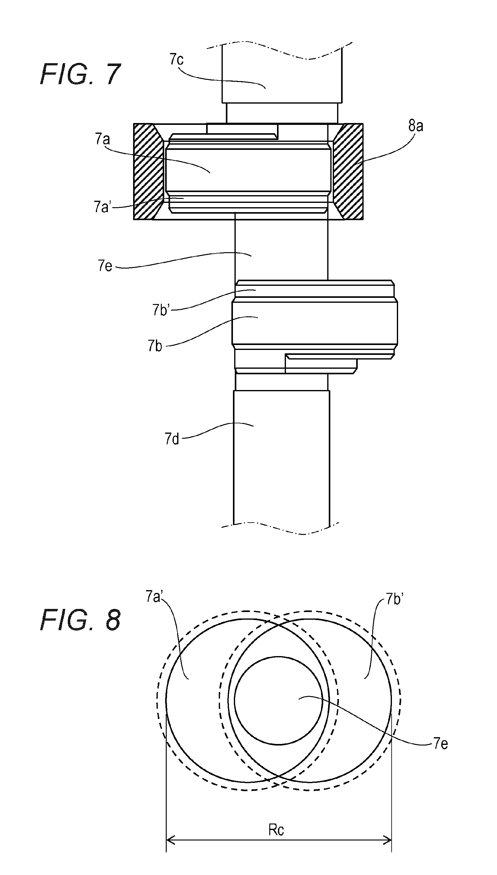
FIG. 7 is a main part side view showing the positional relationship of the crankshaft and the first piston of the rotary compressor during assembly according to the exemplary embodiment of the present invention.
FIG. 8 is a projection of two eccentric portions of the rotary compressor according to the exemplary embodiment of the present invention.
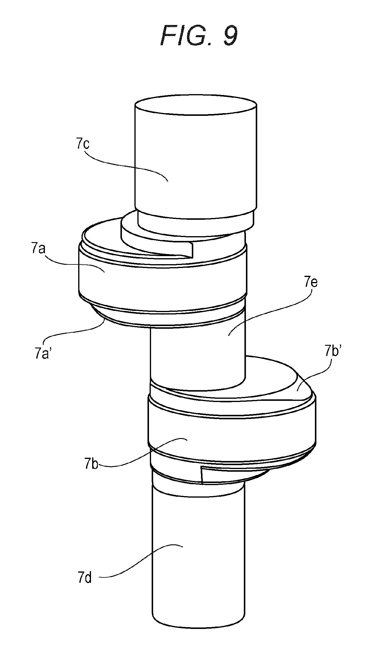
FIG. 9 is an explanatory diagram showing bevel shapes of the eccentric portions in the eccentric direction of the rotary compressor according to the exemplary embodiment of the present invention.
FIG. 10 is a projection of two eccentric portions including the bevel shapes of the eccentric portions in the eccentric direction of the rotary compressor according to the exemplary embodiment of the present invention.
DESCRIPTION OF PREFERRED EMBODIMENTS
Hereinafter, a description will be given of an exemplary embodiment of the present invention with reference to the drawings. Note that, the present invention is not limited by the exemplary embodiment.
FIG. 1 is a vertical cross-sectional view of a rotary compressor according to an exemplary embodiment of the present invention. FIG. 2A is a plan view of a compressive element of the rotary compressor. FIG. 2B is a plan view of the compressive element of the rotary compressor.
In FIG. 1, sealed container 1 houses electrically-operated element 2 and compressive elements 4a, 4b. Electrically-operated element 2 rotates crankshaft 7. Crankshaft 7 drives compressive elements 4a, 4b.
Compressive elements 4a, 4b perform a compression operation independently of each other. Compressive element 4a has cylinder 6a that forms a cylindrical space, and first piston 8a disposed in cylinder 6a. Compressive element 4b has cylinder 6b that forms a cylindrical space, and second piston 8b disposed in cylinder 6b.
Crankshaft 7 is provided with first eccentric portion 7a and second eccentric portion 7b. Partition plate 5 is disposed between two compressive elements 4a, 4b. A main bearing is disposed on the electrically-operated element 2 side relative to compressive element 4a. The main bearing forms, with a bearing portion that pivotally supports main shaft portion 7c, an upper end plate. The upper end plate closes compressive element 4a on the electrically-operated element 2 side. An auxiliary bearing is disposed on the oil reservoir portion 20 side relative to compressive element 4b. The auxiliary bearing forms, with a bearing portion that pivotally supports auxiliary shaft portion 7d, a lower end plate. The lower end plate closes compressive element 4b on the oil reservoir portion 20 side.
Cylinder 6a is disposed at the upper surface of partition plate 5. Cylinder 6b is disposed at the lower surface of partition plate 5. Further, cylinder 6a houses first eccentric portion 7a. Cylinder 6b houses second eccentric portion 7b.
First eccentric portion 7a, second eccentric portion 7b, and connecting portion 7e are structured integrally with crankshaft 7. First piston 8a is mounted on first eccentric portion 7a. Second piston 8b is mounted on second eccentric portion 7b.
As shown in FIGS. 1, 2A and 2B, vane groove 21a is formed at cylinder 6a. At cylinder 6b also, vane groove 21b is formed. Vane 22a is slidably disposed at vane groove 21a. Vane 22b is slidably disposed at vane groove 21b. Vane 22a is constantly coupled to first piston 8a. When first piston 8a oscillates in accordance with the rotation of crankshaft 7, vane 22a reciprocates in vane groove 21a in accordance with the movement of first piston 8a. First piston 8a is structured so as to avoid independent rotation, by being coupled or integrated with vane 22a that oscillates in cylinder 6a. Suction passage 9a is provided at cylinder 6a. Suction passage 9b is provided at cylinder 6b. Suction pipe 10a is connected to suction passage 9a. Suction pipe 10b is connected to suction passage 9b. Suction passage 9a and suction passage 9b are independent of each other. Suction pipe 10a and suction pipe 10b are independent of each other. Suction pipe 10a communicates with compression chamber 11a through suction passage 9a. Suction pipe 10b communicates with compression chamber 11b through suction passage 9b.
Further, in order to prevent liquid compression in compression chambers 11a, 11b, accumulator 12 is provided for suction pipes 10a, 10b. Accumulator 12 separates refrigerant into gas and liquid, and guides only refrigerant gas to suction pipes 10a, 10b. In connection with accumulator 12, refrigerant gas introducing pipe 14 is connected to the upper portion of cylindrical case 13 and two refrigerant gas delivering pipes 15a, 15b are connected to the lower portion. One ends of refrigerant gas delivering pipes 15a, 15b are respectively connected to suction pipes 10a, 10b, and other ends of refrigerant gas delivering pipes 15a, 15b extend to the upper portion of the inner space of case 13.
When electrically-operated element 2 rotates crankshaft 7, first eccentric portion 7a and second eccentric portion 7b eccentrically rotate in cylinders 6a, 6b, and first piston 8a and second piston 8b rotate while causing vanes 22a, 22b to reciprocate. First piston 8a and second piston 8b repeatedly cause, at a cycle shifted by half a rotation from each other, suction and compression of refrigerant gas in cylinders 6a, 6b. The refrigerant of a low pressure suctioned from refrigerant gas introducing pipe 14 is separated into gas and liquid in case 13. The refrigerant gas from which liquid refrigerant has been separated passes through refrigerant gas delivering pipes 15a, 15b, suction pipes 10a, 10b, and suction passages 9a, 9b, and suctioned into compression chambers 11a, 11b.
Further, lubrication oil in oil reservoir portion 20 at the bottom portion of sealed container 1 is supplied from the lower end of auxiliary shaft portion 7d to through hole 5a via the inside of crankshaft 7, so that a region surrounded by partition plate 5, first piston 8a, second piston 8b, and crankshaft 7 is filled with the lubrication oil.
Hereinafter, a description will be given of the operation and effect of the rotary compressor having two cylinders in the above-described structure.
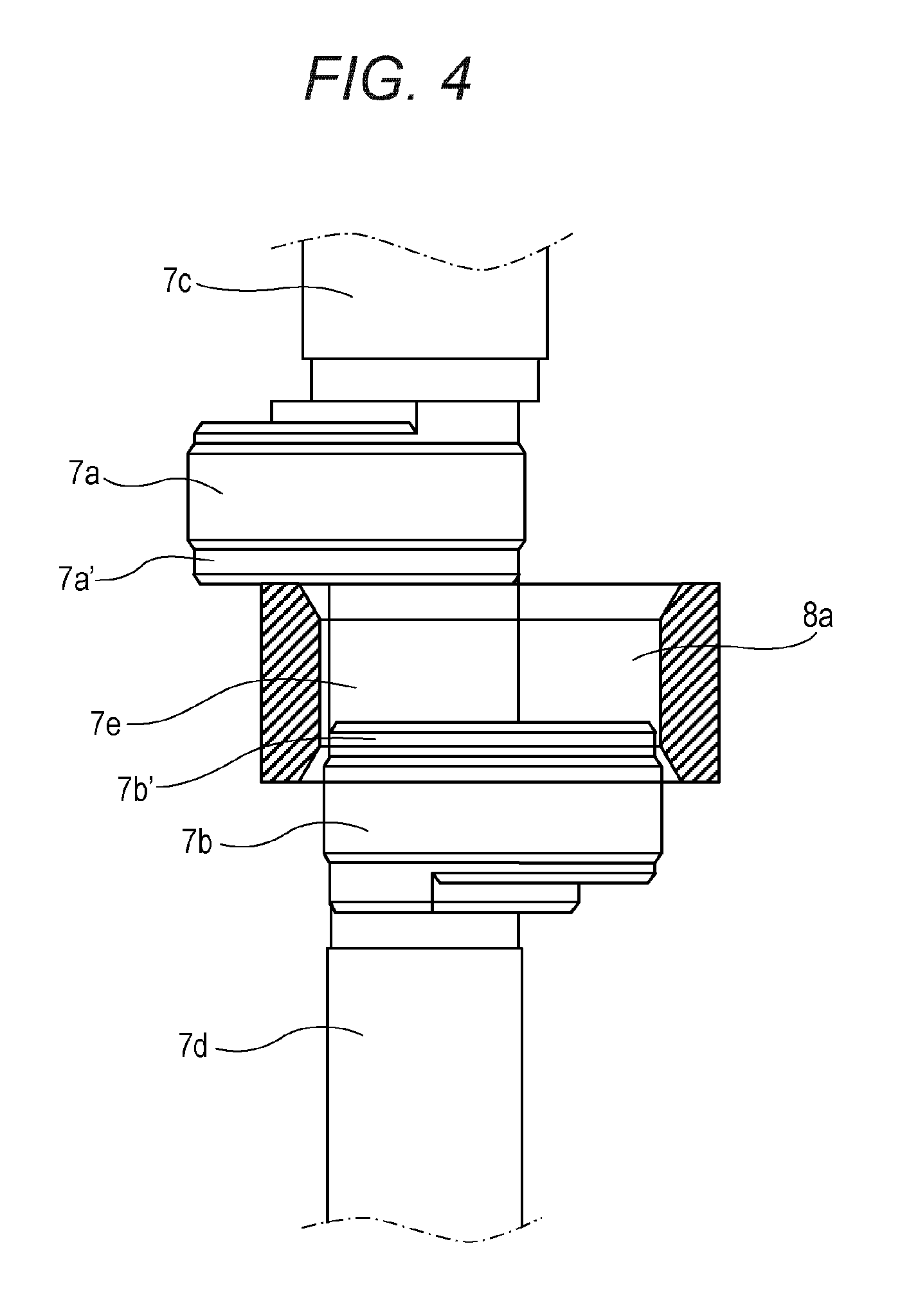
FIG. 3 is a main part side view showing the positional relationship of the crankshaft and the first piston of the rotary compressor during assembly according to the exemplary embodiment of the present invention. FIG. 4 is a main part side view showing the positional relationship of the crankshaft and first piston of the rotary compressor during assembly. FIG. 5 is a main part side view showing the positional relationship of the crankshaft and the first piston of the rotary compressor during assembly. FIG. 6 is a main part side view showing the positional relationship of the crankshaft and the first piston of the rotary compressor. FIG. 7 is a main part side view showing the positional relationship of the crankshaft and the first piston of the rotary compressor during assembly. The assembly of the crankshaft and the first piston of the rotary compressor is performed in order of FIGS. 3, 4, 5, 6, and 7.
In assembly, as shown in FIG. 3, first piston 8a is inserted from the auxiliary shaft portion 7d side, to pass through second eccentric portion 7b and connecting portion 7e. As shown in FIG. 4, first piston 8a is inserted until its upper end is brought into contact with the lower end of first eccentric portion 7a. Thus, the inner diameter portion of first piston 8a is inserted to cover connecting portion 7e and releasing portion 7b' of second eccentric portion 7b.
Here, releasing portion 7b' is structured by a step portion which is concentric to second eccentric portion 7b and with a reduced outer diameter. Thus, releasing portion 7b' can be formed simultaneously with processing of the eccentric shaft, and a reduction in diameter can be suppressed to a minimum.
FIG. 8 is a projection of two eccentric portions of the rotary compressor according to the exemplary embodiment of the present invention. As shown in FIG. 8, the rotary compressor according to the present exemplary embodiment is structured such that outermost diameter Re of a projection cross section, which is obtained by overlaying a cross section of first eccentric portion 7a and that of second eccentric portion 7b excluding releasing portion 7a' of first eccentric portion 7a and releasing portion 7b' of second eccentric portion 7b on each other, is greater than the inner diameter of first piston 8a. Accordingly, unless the inner diameter portion of first piston 8a is completely extracted from second eccentric portion 7b, first piston 8a cannot be inserted over first eccentric portion 7a. Hence, as shown in FIG. 5, as the next insert operation, by first piston 8a rotating and shifting in parallel, first piston 8a can be completely extracted from second eccentric portion 7b.
Further, in FIG. 3, Hc-c<Hp-Hpc<Hc-c+Hcd<Hp is established where Hc-c is the height of connecting portion 7e, Hcd is the height of releasing portions 7a' and 7b', Hp is the height of first piston 8a, and Hpc is the height of one of bevels 8a' and 8b' provided at opposite surfaces of first piston 8a. Accordingly, providing releasing portions 7a' and 7b' respectively to the outer diameter portions of first eccentric portion 7a and second eccentric portion 7b on the connecting portion 7e side realizes a shorter height of the connecting portion than the conventional piston insertion-allowed limit.
Note that, in connection with the inner surface bevels of first piston 8a of the rotary compressor according to the present exemplary embodiment, in order to facilitate shifting to a piston rotation operation, bevel height Hpc in the axial direction is set to be greater than bevel width Cp in the radial direction. Thus, by this amount, connecting portion 7e can be further shortened and rigidity can be increased, without impairing the sealing performance relative to the compression chamber via the end surface of first piston 8a.
In FIG. 6, the operation shown in FIG. 4 is performed symmetrically. Ultimately, as shown in FIG. 7, first piston 8a is completely inserted over first eccentric portion 7a.
Further, releasing portion 7a' of first eccentric portion 7a and releasing portion 7b' of second eccentric portion 7b may be in a manner other than that shown in FIGS. 3 to 7. That is, as shown in FIGS. 9 and 10, the sites of first eccentric portion 7a and second eccentric portion 7b in the eccentric direction may be largely beveled as compared to other sites. In this case also, the assembly procedure is the same as that described above. However, by providing great bevels in the eccentric direction, the inner surface of first piston 8a becomes less prone to be caught by the eccentric portion in the eccentric direction when transiting from the state shown in FIG. 9 to the rotation operation. Further, also when connecting portion 7e is reduced to a limit height, the assembly operation can be smoothly performed.
As described above, the rotary compressor having two cylinders according to the present exemplary embodiment includes crankshaft 7 having first eccentric portion 7a and second eccentric portion 7b connected to each other by connecting portion 7e. The rotary compressor further includes two compressive elements 4a, 4b that compress working fluid in cylinder 6a as first piston 8a inserted over first eccentric portion 7a eccentrically rotates in accordance with rotation of crankshaft 7. Further, first piston 8a inserted over first eccentric portion 7a undergoes assembly by being inserted over first eccentric portion 7a through second eccentric portion 7b. Further, releasing portions 7a', 7b' are respectively provided at outer diameter portions of first eccentric portion 7a and second eccentric portion 7b on the connecting portion 7e side. Further, Hc-c<Hp-Hpc<Hc-c+Hcd<Hp is established, where Hc-c is the height of the connecting portion 7e, Hcd is the height of releasing portions 7a', 7b', Hp is the height of first piston 8a, and Hpc is the height of one of bevels provided at both surfaces of first piston 8a. Still further, the outermost diameter of a projection cross section, which is obtained by overlaying a cross section of first eccentric portion 7a and a cross section of second eccentric portion 7b excluding releasing portions 7a', 7b' on each other, is set to be greater than the inner diameter of first piston 8a.
Accordingly, providing releasing portions 7a', 7b' respectively at the outer diameter portions of first eccentric portion 7a and second eccentric portion 7b on the connecting portion 7e side realizes a shorter height of connecting portion 7e than the conventional piston insertion-allowed limit. Hence, any low-rigidity portion in crankshaft 7 can be reduced to a minimum, and the increased rigidity provides both increased reliability and ensured airtightness of the rotary compressor.
Further, releasing portions 7a', 7b' are respectively structured by step portions being concentric to first eccentric portion 7a and second eccentric portion 7b and having reduced outer diameters. Thus, releasing portions 7a', 7b' can be formed simultaneously with processing of the eccentric shaft, and a reduction in diameter can be suppressed to a minimum. Accordingly, crankshaft 7 of higher rigidity can be structured.
Further, bevel 8a' of first piston 8a is structured to be greater in the axial direction than in the radial direction. Thus, increasing the height of bevel 8a' of first piston 8a enables to increase the rigidity of crankshaft 7 by further reducing the height of connecting portion 7e. Further, it also enables to ensure airtightness of compression chambers 11a, 11b.
Further, in releasing portions 7a', 7b', the sites of first eccentric portion 7a and second eccentric portion 7b in the eccentric direction are largely beveled as compared to other sites. Thus, also in the case where the height of connecting portion 7e is reduced to a minimum, when first piston 8a is inserted from second eccentric portion 7b to connecting portion 7e, and from connecting portion 7e to first eccentric portion 7a, first piston 8a can pass through without being caught by any edge portions of the eccentric portions in the eccentric direction. Accordingly, insertion in assembly can be facilitated.
Further, first piston 8a is structured so as to avoid independent rotation, by being coupled or integrated with vane 22a that oscillates in cylinder 6a. Thus, the piston is restrained by vane 22a from independently rotating, even in the case where first eccentric portion 7a and second eccentric portion 7b rotate in accordance with rotation of crankshaft 7 in a compression operation. Accordingly, first eccentric portion 7a and second eccentric portion 7b can pivotally support the piston forcibly at high relative speeds. Hence, the height of releasing portions 7a', 7b' can be increased by an increased bearing modulus. In accordance therewith, the height of connecting portion 7e can be further reduced, to increase rigidity of crankshaft 7.
INDUSTRIAL APPLICABILITY
As has been described above, the rotary compressor of the present invention can shorten, as compared to the conventional manner, the connecting portion of the crankshaft on the side near the main shaft portion over which the piston must be inserted from the auxiliary shaft portion. This realizes increased rigidity of the crankshaft and improved reliability of the highly efficient compressor. Hence, the rotary compressor of the present invention is useful as an air conditioner-use compressor using an HFC (Hydro Fluoro Carbon)-based refrigerant or the like as working fluid, or for an air conditioner or a heat pump water heater using CO.sub.2 being a natural refrigerant.
* * * * *
D00000
D00001
D00002
D00003
D00004
D00005
D00006
D00007
D00008
D00009
XML
uspto.report is an independent third-party trademark research tool that is not affiliated, endorsed, or sponsored by the United States Patent and Trademark Office (USPTO) or any other governmental organization. The information provided by uspto.report is based on publicly available data at the time of writing and is intended for informational purposes only.
While we strive to provide accurate and up-to-date information, we do not guarantee the accuracy, completeness, reliability, or suitability of the information displayed on this site. The use of this site is at your own risk. Any reliance you place on such information is therefore strictly at your own risk.
All official trademark data, including owner information, should be verified by visiting the official USPTO website at www.uspto.gov. This site is not intended to replace professional legal advice and should not be used as a substitute for consulting with a legal professional who is knowledgeable about trademark law.